Embed Size (px)
Citation preview
ATM/CNS System Architecture Page 1 of 38
ATM/CNS System Architecture
ATM/CNS System Architecture Page 2 of 38
Table of Contents
1 INTRODUCTION ............................................................................................................................... 4
1.1 Context ................................................................................................................ 4
1.2 Definitions ........................................................................................................... 5
1.3 Scope of this Document ...................................................................................... 5
1.4 Airspace in the United Arab Emirates ................................................................. 5
1.5 Periodic Review and Updates .............................................................................. 6
1.6 Regulations, Standards and Guidelines ............................................................... 6
2 ATM/CNS Architecture Overview .................................................................................................. 11
2.1 Current ATM/CNS Architecture ......................................................................... 11
2.2 Planned ATM/CNS Enhancements and Modernisations ................................... 13
2.3 Contingency ....................................................................................................... 13
3 Framework Requirements for Communications ........................................................................... 14
3.1 Introduction ....................................................................................................... 14
3.2 Ground–Ground Communications .................................................................... 14
3.3 Air–Ground Communications ............................................................................ 17
3.4 Other Data Link Services.................................................................................... 22
3.5 System Wide Information Management (SWIM) .............................................. 24
4 Framework Requirements for Navigation ..................................................................................... 28
4.1 Introduction ....................................................................................................... 28
4.2 Distance Measuring Equipment (DME) ............................................................. 28
4.3 VHF Omni-directional Range (VOR) ................................................................... 29
4.4 Instrument Landing System (ILS) ....................................................................... 29
5 Framework Requirements for Surveillance ................................................................................... 30
5.1 Introduction ....................................................................................................... 30
5.2 Primary Surveillance Radar (PSR) ...................................................................... 31
5.3 Secondary Surveillance Radar (SSR) with Mode A, Mode C and Mode S .......... 31
5.4 Multilateration (MLAT) ...................................................................................... 33
5.5 Automatic Dependent Surveillance – Broadcast (ADS-B) ................................. 34
5.6 Automatic Dependent Surveillance – Contract (ADS-C) .................................... 35

ATM/CNS System Architecture Page 3 of 38
5.7 Surface Movement Radar (SMR) ....................................................................... 36
5.8 Surveillance Data Sharing .................................................................................. 37
ATM/CNS System Architecture Page 4 of 38
1 INTRODUCTION
1.1 Context
Through active engagement with the UAE Aviation Community and global aviation stakeholders, the
GCAA is able to identify, understand and focus strategic alignment to ensure common objectives are
developed within the following:
ICAO Global Air Navigation Plan
ICAO MID Region Air Navigation Strategy
UAE Airspace Policy 2015
UAE ATM Strategic Plan
National Airspace Advisory Committee (NASAC)
In 2013 the GCAA contracted a study to evaluate capabilities of the UAE Airspace. This highlighted
Fifty-Three (53) recommendations spanning Airspace, ATM, ATFM and CDM capabilities. Fifteen (15)
of the recommendations were then adopted by the GCAA as ‘Key Recommendations’ to ensure
action plans were developed to enable these highlighted capability requirements. Within the fifteen
(15) recommendations the following key recommendations were highlighted:
4. Develop and implement a plan to manage UAE air navigation service provision that is
seamless from a stakeholder perspective, including requirements, system capabilities, and
coordination.
5. Develop and implement a UAE-wide Enterprise Architecture for the provision of air navigation
services and information, including military.
9. Establish Collaborative Decision Making (CDM) capabilities and processes for exchanging
strategic and tactical information and decision making between the ANSPs and stakeholders,
including Airport Operators.
14. Foster UAE regional leadership through implementation of leading-edge capabilities and
establishment of focused ATFM capabilities.
As part of the Key Recommendation 5: Develop and implement a UAE-wide Enterprise Architecture
for the provision of air navigation services and information, including military. NASAC WG 15 is
developing an ATM/CNS architecture for the UAE that does not only guarantee safe, secure and
effective operations for the UAE, but to also harness future capabilities from modern aircraft and
airspace, ensuring enablement of appropriately scalable seamless interoperability and harmonisation
to support a State-of-the-Art and Future Proof ATM System.
ATM/CNS System Architecture Page 5 of 38
The aim is that for the ATM/CNS framework is to provide recommendations and best practises to be
considered for when ATM/CNS systems are implemented or renewed.
1.2 Definitions
Interoperability Functional, technical and operational properties which the systems and constituents of
ATM/CNS architecture must have and the procedures for operation in order to ensure
safe, efficient and seamless operation in the UAE.
System Ground and airborne constituents to support air navigation services during all phases
of flight.
Constituents Tangible items, such as equipment, and intangible items, such as the software on
which the interoperability of the ATM/CNS architecture depends
Seamless operation Operation of the ATM/CNS architecture in such a way that, for the (airspace) users, it
acts as a single entity.
1.3 Scope of this Document
The objective of this document is to complement UAE Aviation Strategy by providing guidance to
aviation stakeholders on recommended systems and technologies to build an ATM/CNS
infrastructure for air traffic services in the UAE. Despite the recommendations all systems are
required to be in line with the national regulations and shall conform to regional and global
standards.
In the following is a guidance for Communication, Navigation and Surveillance (CNS) technologies
that shall support harmonisation of ATM/CNS in the UAE.
1.4 Airspace in the United Arab Emirates
1.4.1 Emirates FIR
The Emirates FIR is among the smallest and most important blocks of airspace in the world. This is
due to the strategic location of the UAE being the link between East and West. Civil Traffic in the UAE
airspace controlled by several Air Traffic Service Units that closely work together to safely and
efficiently manage the flow of air traffic.
ATM/CNS System Architecture Page 6 of 38
SZC With a size of approximately 124,000 square km Emirates FIR hosts more
than 40 international airways. SZC subdivides the controlled airspace into
11 sector. Depending on traffic demand individual sectors may be
combined to increase the efficiency.
ADAC-ANS ADAC ANS are responsible for all aircraft arriving and departing from Abu
Dhabi and Al Ain airport. This includes approach services for the airports
at Abu Dhabi CTA and provide tower services at both airports
DANS Dubai ANS ATC are responsible for all aircraft arriving and departing from
Dubai and the northern Emirates. This includes approach services for five
airports (DXB, DWC, Sharjah International, Ras Al Khaimah International,
and Al Minhad Air Base) from a combined facility at DWC and provide
tower services at both Dubai International (DXB) and Al Maktoum (DWC).
Ras Al Khaimah-ANS Ras Al Khaimah-ANS provides approach and tower services for Ras Al
Khaimah airport.
Sharjah -ANS Sharjah-ANS tower services for Sharjah airport.
Fujairah -ANS Fujairah-ANS provide approach and tower services for Fujairah airport.
1.5 Periodic Review and Updates
This document will need to evolve as operational needs and technology is evolving. It should be
therefore be reviewed and updated as necessary once per year.
1.6 Regulations, Standards and Guidelines
The following list provides the references used within this document. This is a non-exhaustive list of
regulations that need to be considered and complied with when CNS and ATM systems are
implemented and operated.
1.6.1 Regulations
Having regard to Article 10 of the United Arab Emirates (UAE) General Civil Aviation Authority Law
No. 4 of 1996, whereas the General Civil Aviation Authority (GCAA), as the Competent Authority,
shall promulgate the necessary regulations to implement the provisions of the Civil Aviation Law No.
20 of 1991.
ATM/CNS System Architecture Page 7 of 38
For the purpose of this document the following Civil Aviation Regulations (CAR) have been
considered
/01/ UAE Civil Aviation Regulations (CAR)
https://www.gcaa.gov.ae/en/ePublication/Pages/CARs.aspx
1.6.2 Standards and Guidelines
1.6.2.1 UAE Strategic Framework
/02/ UAE ATM Strategic Plan, Guidance Material No.04
1.6.2.2 ICAO References
/03/ ICAO Doc 4444, Procedure of Air Navigation Services Air Traffic Management (PANS-
ATM)
/04/ ICAO Doc 9750, Global Air Navigation Plan
/05/ ICAO Doc 9694, Manual of Air Traffic Services
/06/ ICAO Doc 8400, ICAO Abbreviations and Codes
/07/ ICAO Doc 9694, Manual of Air Traffic Service Data Link Applications
/08/ ICAO Doc 9854, Global Air Traffic Management Operational Concept
/09/ ICAO Doc 9882, Manual on Air Traffic Management (ATM) System Requirements
/01/ ICAO Doc 7192, Training Manual (Part E-2): Air Traffic Safety Electronics Personnel
(ATSEP)
/02/ ICAO Doc 9971, Manual on Collaborative Air Traffic Flow Management
/03/ ICAO Doc 9643, Manual on Simultaneous Operations on Parallel or Near Parallel
Instrumented Runways (SOIR)
/04/ ICAO Doc 10004, Global Aviation Safety Plan 2014-2016
/05/ ICAO Doc 10039, Manual on System Wide Information Management (SWIM) Concept
/06/ ICAO Annex 2: Rules of the Air
/07/ ICAO Annex 3: Meteorological Service for International Air Navigation
/08/ ICAO Annex 4: Aeronautical Charts
/09/ ICAO Annex 5: Units of Measurement to be Used in Air and Ground Operations
/10/ ICAO Annex 10 Volume I: Radio Navigation Aids
/11/ ICAO Annex 10 Volume II: Communications Procedures including those with PANS
status
/12/ ICAO Annex 10 Volume III: Aeronautical Telecommunications, Part 1: Digital Data
Communication Systems
/13/ ICAO Annex 10 Volume III: Aeronautical Telecommunications, Part 2: Voice
Communication Systems
/14/ ICAO Annex 10 Volume IV: Surveillance Radar and Collision Avoidance Systems
/15/ ICAO Annex 10 Volume V: Aeronautical Radio Frequency Spectrum Utilization
/16/ ICAO Annex 11: Air Traffic Services
/17/ ICAO Annex 14: Aerodromes

ATM/CNS System Architecture Page 8 of 38
/18/ ICAO Annex 15: Security: Safeguarding International Civil Aviation Against Acts of
Unlawful Interference
1.6.2.3 References for Surveillance Performance
/19/ Eurocontrol-SPEC-0147: Specification for ATM Surveillance System Performance
(ESASSP), Edition 1.1, 01.09.2015
/20/ Eurocontrol Radar Sensor Performance Analysis, SUR.ET1.ST03.1000-STD-01-01,
Edition 0.1, 01.06.1997
/21/ Eurocontrol Standard for Radar Surveillance in En-Route Airspace and Major Terminal
Areas. Edition May, 1996
1.6.2.4 References for ASTERIX
/22/ Eurocontrol ASTERIX Standard Document for Surveillance Data Exchange, Part 1: All
Purpose Structured Eurocontrol Surveillance Information Exchange,
SUR.ET1.ST05.2000-STD-01-01, Edition 1.30, 19.11.2007
1.6.2.5 References and Guidance for Safety Nets
/23/ Eurocontrol-SPEC-122, Eurocontrol Specification for Short Term Conflict Alert, Edition
1.1, 19.05.2009 (STCA)
/24/ Eurocontrol-SPEC-124, Eurocontrol Specification for Area Proximity Warning, Edition
1.0, 19.05.2009 (APW)
/25/ Eurocontrol-SPEC-126, Eurocontrol Specification for Minimum Safe Altitude Warning,
Edition 1.1, 19.05.2009 (MSAW)
/26/ Eurocontrol-SPEC-126, Eurocontrol Specification for Approach Path Monitor, Edition
0.5, 19.05.2009 (APM)
/27/ Eurocontrol-SPEC-139, Eurocontrol Specification for Medium-Term Conflict Detection,
Edition 1.0, 15.07.2019 (MTCD)
/28/ Eurocontrol EAM 4/GUI 6: ESARR Advisory Material/Guidance Material (EAM/GUI)
Explanatory material On Ground Based Safety Nets
/29/ ED-99B: User Requirements for Aerodrome Mapping Information
/30/ ED-119A: Interchange Standards for Terrain, Obstacles, and Aerodrome Mapping Data
/31/ DRAFT Eurocontrol Initial Specification for Display of Downlinked ACAS II Resolution
Advisories at Controller Working Positions (RA Downlink), Edition 0.4, 15. November
2010
1.6.2.6 Data Link Services
/32/ ARINC 622: ATS Data Link Applications over ACARS Air-Ground Network
/33/ EUROCAE ED-100/RTCA DO-258 Interoperability Requirements for ATS Applications
Using ARINC 622 Data Communications

ATM/CNS System Architecture Page 9 of 38
1.6.2.7 Arrival Manager
/34/ Eurocontrol Arrival Manager, Implementation Guidelines and lessons Learned, Edition
0.1, 17. December 2010
1.6.2.8 Ground Based Recording
/35/ ED-111: Functional Specifications for CNS/ATM Recording
(including amendment no.1, 30.07.2003)
1.6.2.9 Abbreviations and Acronyms
The following list of abbreviations lists the abbreviations used in this document.
ACAS Airborne Collision Avoidance
System
ACC Area Control Centre
ADAC Abu Dhabi Airports Company
AFTN Aeronautical Fixed
Telecommunication Network
AIDC ATS Interfacility Data
Communication
AIM Aeronautical Information
Management
AIXM Aeronautical Information
Exchange Model
AMHS Aeronautical Message Handling
System
ANA Air Navigation and Aerodrome
Department
ANSP Air Navigation Service Provider
ASBU Aviation System Block Upgrade
ASTERIX All Purpose Structured
Eurocontrol Surveillance
Information Exchange
ATC Air Traffic Control
ATCO Air Traffic Control Officer
ATFCM Air Traffic Flow and Capacity
Management
ATFM Air Traffic Flow Management
ATS Air Traffic Service
ATSI Air Traffic Service Instructor
ATSU Air Traffic Service Unit
CDM Collaborative Decision Making
CPDLC
Controller-Pilot Data Link
Communications
DANS Dubai Air Navigation Services
DFLOW Departure Flow Manager
ESASSP Eurocontrol Specification for
ATM Surveillance System
Performance
EUROCAE European Organisation for Civil
Aviation Equipment
FIR Flight Information Region
GANP Global Air Navigation Plan
GCAA General Civil Aviation Authority
GCC Cooperation Council for the
Arab States of the Gulf
ICAO International Civil Aviation
Organization
MTCD Medium Term Conflict
Detection
SDPS Surveillance Data Processing
System

ATM/CNS System Architecture Page 10 of 38
STCA Short Term Conflict Alert
SWIM System Wide Information
Management
SZC Sheikh Zayed Air Navigation
Centre
TBS Time Based Operation
UAE The United Arab Emirates
XML Extensible Markup Language

ATM/CNS System Architecture – Issue 1 Page 11 of 38
2 ATM/CNS Architecture Overview
2.1 Current ATM/CNS Architecture
The following table shows an overview of equipment in use at various sites. Depending on the equipment in
Abu Dhabi, Dubai and Fujairah, ATC Tower systems are either part of/directly connected to the data
processing of the respective approach system or are standalone equipment.
SZ
C
Ab
u D
hab
i Ap
pro
ach
Ab
u D
hab
i To
wer
Al A
in T
ow
er
Al B
atee
n T
ow
er
Du
bai
Ap
pro
ach
Du
bai
To
wer
Al M
akto
um
To
wer
Fuja
irah
Ap
pro
ach
Fuja
irah
To
wer
Shar
jah
To
wer
Ras
Al K
hai
mah
To
wer
Surveillance System
Air Situation Display X X X X X X X X X X X X
Surveillance Radar X X X
ADS B Ground Station X X
Multilateration System X X X
Surveillance Data Processing X X X X
A-SMGCS X X X X
Communication Systems
VCCS X X X
Flight Plan Systems
AFTN/AMHS Switch X X X X X x x
Flight Plan Data Processing X X X X X X
OLDI Coordination X X X X X
Electronic Flight Strips
Safety Nets X X X
Capacity and Flow Management
Arrival Manager X
AMAN Terminal X X
ATM/CNS System Architecture – Issue 1 Page 12 of 38
Departure Manager
DFLOW X
DFLOW Terminal X X X
Data Link
DCL X X X
CPDLC
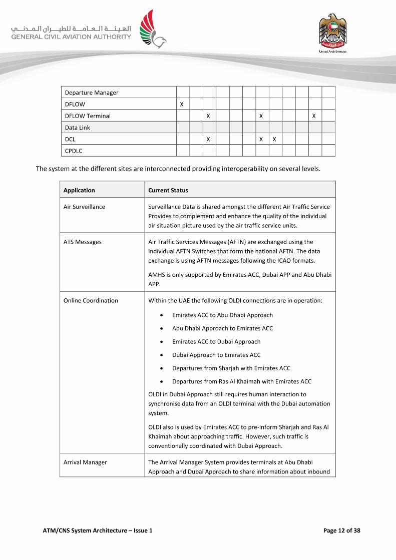
The system at the different sites are interconnected providing interoperability on several levels.
Application Current Status
Air Surveillance Surveillance Data is shared amongst the different Air Traffic Service
Provides to complement and enhance the quality of the individual
air situation picture used by the air traffic service units.
ATS Messages Air Traffic Services Messages (AFTN) are exchanged using the
individual AFTN Switches that form the national AFTN. The data
exchange is using AFTN messages following the ICAO formats.
AMHS is only supported by Emirates ACC, Dubai APP and Abu Dhabi
APP.
Online Coordination Within the UAE the following OLDI connections are in operation:
Emirates ACC to Abu Dhabi Approach
Abu Dhabi Approach to Emirates ACC
Emirates ACC to Dubai Approach
Dubai Approach to Emirates ACC
Departures from Sharjah with Emirates ACC
Departures from Ras Al Khaimah with Emirates ACC
OLDI in Dubai Approach still requires human interaction to
synchronise data from an OLDI terminal with the Dubai automation
system.
OLDI also is used by Emirates ACC to pre-inform Sharjah and Ras Al
Khaimah about approaching traffic. However, such traffic is
conventionally coordinated with Dubai Approach.
Arrival Manager The Arrival Manager System provides terminals at Abu Dhabi
Approach and Dubai Approach to share information about inbound
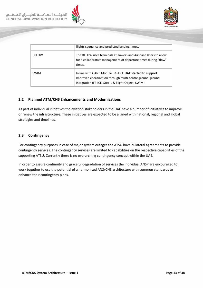
ATM/CNS System Architecture – Issue 1 Page 13 of 38
flights sequence and predicted landing times.
DFLOW The DFLOW uses terminals at Towers and Airspace Users to allow
for a collaborative management of departure times during “flow”
times.
SWIM In line with GANP Module B2–FICE UAE started to support
Improved coordination through multi-centre ground-ground
integration (FF-ICE, Step 1 & Flight Object, SWIM).
2.2 Planned ATM/CNS Enhancements and Modernisations
As part of individual initiatives the aviation stakeholders in the UAE have a number of initiatives to improve
or renew the infrastructure. These initiatives are expected to be aligned with national, regional and global
strategies and timelines.
2.3 Contingency
For contingency purposes in case of major system outages the ATSU have bi-lateral agreements to provide
contingency services. The contingency services are limited to capabilities on the respective capabilities of the
supporting ATSU. Currently there is no overarching contingency concept within the UAE.
In order to assure continuity and graceful degradation of services the individual ANSP are encouraged to
work together to use the potential of a harmonised ANS/CNS architecture with common standards to
enhance their contingency plans.

ATM/CNS System Architecture – Issue 1 Page 14 of 38
3 Framework Requirements for Communications
3.1 Introduction
The safety and efficiency of air traffic control is directly related to the availability and performance of
aeronautical communications and the supporting infrastructure. The importance of communications is
highlighted by the scope of air traffic management and airline operations that depend upon it. This scope of
operations includes filing and amending flight plans, Air Traffic Services (ATS) communications, and airline
operational communications. Implementations of any communication capability can have a wide-ranging
effect and thus require proper multidisciplinary coordination involving aircraft operators, avionics
manufacturers, flight crews, ANSPs and other agencies providing supporting services and infrastructure.
The following sections identify the ground-to-ground and air-to-ground / ground-to-air subnetworks of the
Communication Network, and the various technologies and their deployment.
3.2 Ground–Ground Communications
Ground-ground communications refer to exchanges of ATM-related messages linking ground-based
stakeholders concerning planning and movement of aircraft. Such communications are transitioning from
analogue to digital format and are becoming increasingly automated.
Technologies and applications reviewed in this section include:
Aeronautical Fixed Telecommunications Network (AFTN) and ATS Message Handling Services (AMHS);
Air Traffic Services Inter-Facility Data Communications (AIDC)
On-Line Data Interchange (OLDI)
3.2.1 Aeronautical Fixed Telecommunications Network and ATS Message Handling Services
The AFTN is a message-handling network that has existed for over 50 years. It is a closed network in the
sense that its users belong to ATS authorities and associated organizations such as airline operators, general
aviation, and meteorological offices. Access to the network will require the operators of network nodes to
actively establish connection to new nodes and/or client systems.
The AFTN is character-based only and cannot carry bit-oriented applications. This is a heritage from the time
the ATFN was based in Telex (Teleprinter) networks. While the pure character based ATFN is a limited factor
for innovations on the positive side it is a sound bases for a global interoperability. ATS messages as per
ICAO or ADEXP format can exchanged globally between organisations and systems of different age and
origin.
ATM/CNS System Architecture – Issue 1 Page 15 of 38
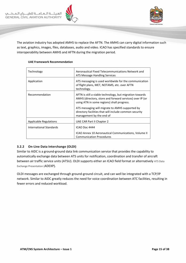
The aviation industry has adopted AMHS to replace the AFTN. The AMHS can carry digital information such
as text, graphics, images, files, databases, audio and video. ICAO has specified standards to ensure
interoperability between AMHS and AFTN during the migration period.
UAE Framework Recommendation
Technology Aeronautical Fixed Telecommunications Network and ATS Message Handling Services
Application ATS messaging is used worldwide for the communication of flight plans, MET, NOTAMS, etc. over AFTN technology.
Recommendation AFTN is still a viable technology, but migration towards AMHS (directory, store and forward services) over IP (or using ATN in some regions) shall progress.
ATS messaging will migrate to AMHS supported by directory facilities that will include common security management by the end of
Applicable Regulations UAE CAR Part II Chapter 2
International Standards ICAO Doc 4444
ICAO Annex 10 Aeronautical Communications, Volume II Communication Procedures
3.2.2 On-Line Data Interchange (OLDI)
Similar to AIDC is a ground-ground data link communication service that provides the capability to
automatically exchange data between ATS units for notification, coordination and transfer of aircraft
between air traffic service units (ATSU). OLDI supports either an ICAO field format or alternatively ATS Data
Exchange Presentation (ADEXP).
OLDI messages are exchanged through ground-ground circuit, and can well be integrated with a TCP/IP
network. Similar to AIDC greatly reduces the need for voice coordination between ATC facilities, resulting in
fewer errors and reduced workload.

ATM/CNS System Architecture – Issue 1 Page 16 of 38
UAE Framework Recommendation
Technology On-Line Data Interchange (OLDI)
Application Ground-Ground Coordination
Improved and automatic coordination between ATSUs using On-Line Data Interchange (OLDI)
Recommendation Implementation of OLDI is strongly encouraged.
At least a minimal subset of functionality shall be supported by all ATSU owning an ATM automation system. The basic set of messages shall include ABI, ACT, PAC, LAM and COD (Basic OLDI).
Implementation shall use FMTP over TCP/IP. The use of obsolete X.25 technology shall be avoided.
Applicable Regulations N/A
International Standards Eurocontrol Specification for On-Line Data Exchange (OLDI), Edition 4.30
Eurocontrol Specification of Interoperability and Performance Requirements for the Flight Message Transfer Protocol (FMTP), Edition 2.0, 2007-06-14
3.2.3 Air Traffic Services Interfacility Data Communication (AIDC)
AIDC is a ground-ground data link communication service that provides the capability to automatically
exchange data between ATS units for notification, coordination and transfer of aircraft between air traffic
service units (ATSU). AIDC message format and procedures is an international standard designed for use
through any ground-ground circuit, including the legacy AFTN.
AIDC greatly reduces the need for voice coordination between ATC facilities, resulting in fewer errors and
reduced workload.

ATM/CNS System Architecture – Issue 1 Page 17 of 38
UAE Framework Recommendation
Technology Air Traffic Services Interfacility Data Communication (AIDC)
Application Improved and automatic coordination between ATSUs using Improved and automatic coordination between ATSUs using On-Line Data Interchange (OLDI)
Recommendation Preference shall be given to OLDI as it assures monitoring of the connections.
Applicable Regulations N/A
International Standards ICAO Doc 4444
ICAO Document 9694
3.3 Air–Ground Communications
Current controller-pilot communications use primarily voice links provided by analogue radios operating in
the VHF bands. Aviation is moving towards a new communications infrastructure that provides superior
quality through use of air-ground data link. A first generation of ATC applications was implemented using
Aircraft Communications Addressing and Reporting System (ACARS) air-ground data links. ACARS now needs
to transition to modern communications protocols, such as VDL Mode 2, in order to support increasing user
traffic and provide the performance needed for today and future air traffic management (ATM).
The objective is to adopt Controller Pilot Datalink Communications (CPDLC) as the primary means of routine
communication while maintaining the requirement for voice communications for non-routine, tactical
communications and as a backup. Ground-ground communications refer to exchanges of ATM-related
messages linking ground-based stakeholders concerning planning and movement of aircraft. Such
communications are transitioning from analogue to digital format and are becoming increasingly automated.

ATM/CNS System Architecture – Issue 1 Page 18 of 38
Technologies and applications reviewed in this section include:
Voice Communication
► Very High Frequency (VHF) Voice
► High Frequency (HF) Voice
► Voice Communications through Satellites (SATVOICE)
Data and Network Communication
► Controller Pilot Data Link Communications (CPDLC)
► Aircraft Communications Addressing and Reporting System (ACARS)
► VHF Data Link (VDL) Modes 2–4
► Aeronautical Telecommunications Network (ATN)
In addition to the above Air-Communication in the vicinity of aerodromes is an emerging element of
communications. In this domain two technologies currently are under consideration.
Communication in the vicinity of aerodromes
► Aeronautical Mobile Airport Communications System (AeroMACS)
► Long Term Evolution (LTE)
At his time, in the UAE Air Air–Ground communications in the vicinity of aerodrome is not used and the UAE
Framework does not recommend for a certain technology.
3.3.1 Very High Frequency (VHF) Voice
VHF voice communication systems, used in the International Aeronautical Mobile Service are amplitude
modulated (AM) carriers. VHF analogue radios use channels of varying bandwidth. The channel spacing can
be defined as 100 kHz, 50 kHz, 25 kHz or 8.33 kHz, depending on the saturation of channels in the region of
interest.

ATM/CNS System Architecture – Issue 1 Page 19 of 38
UAE Framework Recommendation
Technology Very High Frequency (VHF)
Application Voice Air–Ground Communications
Recommendation N/A
Applicable Regulations N/A
International Standards N/A
3.3.2 High Frequency (HF) Voice
HF communications have long-distance coverage and aircraft can use radios operating in the HF radio band
for long-range communications because signals are reflected by the ionosphere. Link quality and availability
are variable, and influenced by a number of factors, including frequency congestion, sunspot activity, solar
cycle, and day/night atmospheric and ionospheric conditions.
UAE Framework Recommendation
Technology High Frequency (HF)
Application Voice Air–Ground Communications
Recommendation N/A
Applicable Regulations ICAO Manual on Testing Radio Navigation Aids (Doc 8071); Volume III – Testing of Surveillance Radar System
International Standards N/A
3.3.3 Controller Pilot Data Link Communications (CPDLC)
CPDLC is a method by which the ATC units can communicate with aircraft over a digital datalink. Communication
is using pre-defined message sets, with a free-text option for non-routine messages. CPDLC is a desirable
form of controller-pilot communications, as it reduces voice errors and misinterpretations. It can be used for
routine communications but due to potential delays is less suitable for tactical interventions as compared
with VHF voice communications.

ATM/CNS System Architecture – Issue 1 Page 20 of 38
UAE Framework Recommendation
Technology Controller Pilot Data Link Communications (CPDLC)
Application Air–Ground Data Link Communications
Recommendation N/A
Applicable Regulations N/A
Recommended Practises ICAO Doc 4444
ICAO Document 9694
ARINC 622
EUROCAE ED-100/RTCA DO-258
3.3.4 Aircraft Communications Addressing and Reporting System (ACARS)
Aircraft Communication and Reporting System (ACARS) systems were originally used to exchange messages
between aircraft and flight operations centres. Today the ACARS network and avionics are used to support
the exchange of FANS 1/A messages (i.e. Automatic Dependent Surveillance-Contract (ADS-C) and Controller
Pilot Data Link Communications (CPDLC)) between aircraft and ATS units.
Use of ACARS for ATS communications has reduced potential for error inherent in voice communications,
and off-loaded congested ATS voice channels. ACARS is currently available via HF, VHF and satellite data
links.
UAE Framework Recommendation
Technology Aircraft Communications Addressing and Reporting System (ACARS)
Application Air–Ground Data Link Communications
Recommendation Based on current equipage ACARS is recommended as the bases for initial datalink within the UAE
Applicable Regulations N/A
International Standards N/A
3.3.5 VHF Data Link (VDL) Mode 2
VDL Mode 2 is a bit-oriented air-ground digital data link that was introduced as an VHF Mode 0 (VHF ACARS)
upgrade for ATC controller-pilot data communications while still allowing ACARS equipped aircraft to use the
same network. Being bit-oriented, it can transmit digital content rather than being limited to characters.
ATM/CNS System Architecture – Issue 1 Page 21 of 38
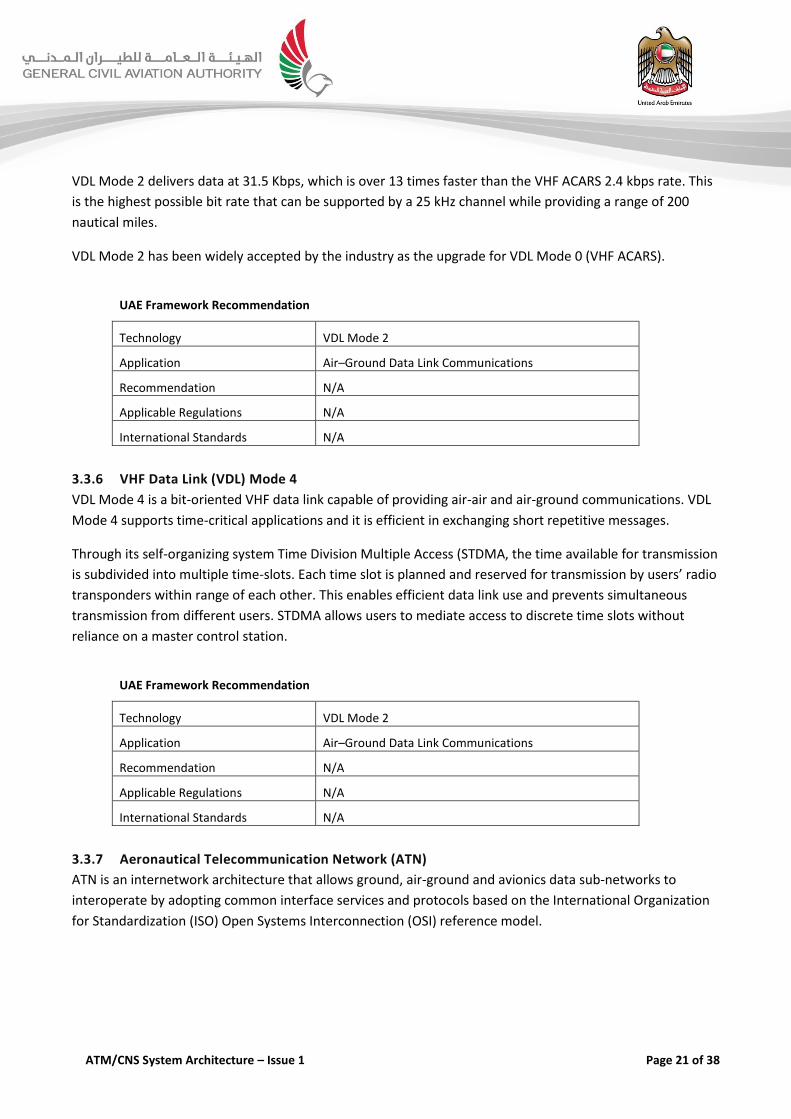
VDL Mode 2 delivers data at 31.5 Kbps, which is over 13 times faster than the VHF ACARS 2.4 kbps rate. This
is the highest possible bit rate that can be supported by a 25 kHz channel while providing a range of 200
nautical miles.
VDL Mode 2 has been widely accepted by the industry as the upgrade for VDL Mode 0 (VHF ACARS).
UAE Framework Recommendation
Technology VDL Mode 2
Application Air–Ground Data Link Communications
Recommendation N/A
Applicable Regulations N/A
International Standards N/A
3.3.6 VHF Data Link (VDL) Mode 4
VDL Mode 4 is a bit-oriented VHF data link capable of providing air-air and air-ground communications. VDL
Mode 4 supports time-critical applications and it is efficient in exchanging short repetitive messages.
Through its self-organizing system Time Division Multiple Access (STDMA, the time available for transmission
is subdivided into multiple time-slots. Each time slot is planned and reserved for transmission by users’ radio
transponders within range of each other. This enables efficient data link use and prevents simultaneous
transmission from different users. STDMA allows users to mediate access to discrete time slots without
reliance on a master control station.
UAE Framework Recommendation
Technology VDL Mode 2
Application Air–Ground Data Link Communications
Recommendation N/A
Applicable Regulations N/A
International Standards N/A
3.3.7 Aeronautical Telecommunication Network (ATN)
ATN is an internetwork architecture that allows ground, air-ground and avionics data sub-networks to
interoperate by adopting common interface services and protocols based on the International Organization
for Standardization (ISO) Open Systems Interconnection (OSI) reference model.
ATM/CNS System Architecture – Issue 1 Page 22 of 38
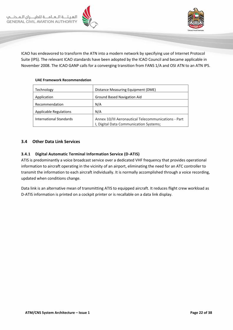
ICAO has endeavored to transform the ATN into a modern network by specifying use of Internet Protocol
Suite (IPS). The relevant ICAO standards have been adopted by the ICAO Council and became applicable in
November 2008. The ICAO GANP calls for a converging transition from FANS 1/A and OSI ATN to an ATN IPS.
UAE Framework Recommendation
Technology Distance Measuring Equipment (DME)
Application Ground Based Navigation Aid
Recommendation N/A
Applicable Regulations N/A
International Standards Annex 10/III Aeronautical Telecommunications - Part I, Digital Data Communication Systems;
3.4 Other Data Link Services
3.4.1 Digital Automatic Terminal Information Service (D-ATIS)
ATIS is predominantly a voice broadcast service over a dedicated VHF frequency that provides operational
information to aircraft operating in the vicinity of an airport, eliminating the need for an ATC controller to
transmit the information to each aircraft individually. It is normally accomplished through a voice recording,
updated when conditions change.
Data link is an alternative mean of transmitting ATIS to equipped aircraft. It reduces flight crew workload as
D-ATIS information is printed on a cockpit printer or is recallable on a data link display.
ATM/CNS System Architecture – Issue 1 Page 23 of 38
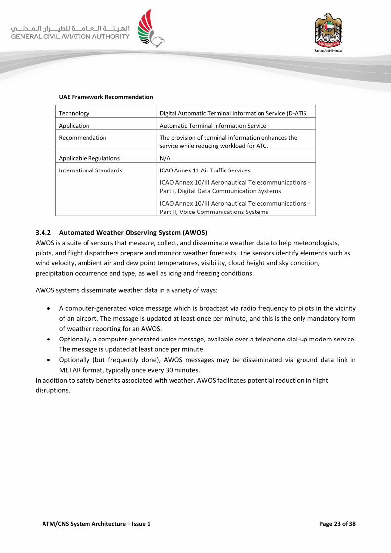
UAE Framework Recommendation
Technology Digital Automatic Terminal Information Service (D-ATIS
Application Automatic Terminal Information Service
Recommendation The provision of terminal information enhances the service while reducing workload for ATC.
Applicable Regulations N/A
International Standards ICAO Annex 11 Air Traffic Services
ICAO Annex 10/III Aeronautical Telecommunications - Part I, Digital Data Communication Systems
ICAO Annex 10/III Aeronautical Telecommunications - Part II, Voice Communications Systems
3.4.2 Automated Weather Observing System (AWOS)
AWOS is a suite of sensors that measure, collect, and disseminate weather data to help meteorologists,
pilots, and flight dispatchers prepare and monitor weather forecasts. The sensors identify elements such as
wind velocity, ambient air and dew point temperatures, visibility, cloud height and sky condition,
precipitation occurrence and type, as well as icing and freezing conditions.
AWOS systems disseminate weather data in a variety of ways:
A computer-generated voice message which is broadcast via radio frequency to pilots in the vicinity
of an airport. The message is updated at least once per minute, and this is the only mandatory form
of weather reporting for an AWOS.
Optionally, a computer-generated voice message, available over a telephone dial-up modem service.
The message is updated at least once per minute.
Optionally (but frequently done), AWOS messages may be disseminated via ground data link in
METAR format, typically once every 30 minutes.
In addition to safety benefits associated with weather, AWOS facilitates potential reduction in flight
disruptions.

ATM/CNS System Architecture – Issue 1 Page 24 of 38
UAE Framework Recommendation
Technology Automated Weather Observing System (AWOS)
Application Weather Observing
Recommendation The use of AWOS and its integration into automation systems is recommended.
Applicable Regulations N/A
International Standards N/A
3.5 System Wide Information Management (SWIM)
System Wide Information Management (SWIM) is an emerging architectural platform as per Global Air
Navigation Plan. As part of a global harmonization and improved interoperability it will be deployed
worldwide in the coming years and will become an essential the foundations of the ATM system. The
development of suitable high level principles or guidelines to identify essential Modules at a global level will
be necessary.
Considering safety and interoperability as basic targets, such principles could, focus, for example, on those
Modules providing:
direct and tangible safety improvements;
interoperability of ground-to-ground systems, recognizing the desirability of automation systems to be able to
effectively communicate globally; and
interoperability of air-to-air systems, recognizing the need for airborne applications to be able to interact
without restriction.
As part of ICAO’s global strategy SWIM is a technology that will provide the platform for various information
and applications. It addresses basic access methodologies and deals with security. As a platform it is the
bases for the gradual migration of existing applications to this technology and will enable introduction of
new and enhanced applications. On global scale a number of initial applications are already existing, such as
the Eurocontrol Network Manager.
ATM/CNS System Architecture – Issue 1 Page 25 of 38
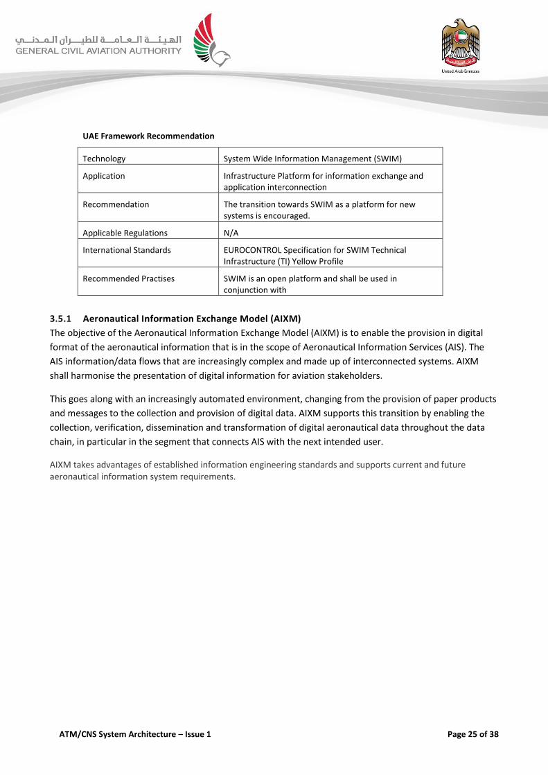
UAE Framework Recommendation
Technology System Wide Information Management (SWIM)
Application Infrastructure Platform for information exchange and application interconnection
Recommendation The transition towards SWIM as a platform for new systems is encouraged.
Applicable Regulations N/A
International Standards EUROCONTROL Specification for SWIM Technical Infrastructure (TI) Yellow Profile
Recommended Practises SWIM is an open platform and shall be used in conjunction with
3.5.1 Aeronautical Information Exchange Model (AIXM)
The objective of the Aeronautical Information Exchange Model (AIXM) is to enable the provision in digital
format of the aeronautical information that is in the scope of Aeronautical Information Services (AIS). The
AIS information/data flows that are increasingly complex and made up of interconnected systems. AIXM
shall harmonise the presentation of digital information for aviation stakeholders.
This goes along with an increasingly automated environment, changing from the provision of paper products
and messages to the collection and provision of digital data. AIXM supports this transition by enabling the
collection, verification, dissemination and transformation of digital aeronautical data throughout the data
chain, in particular in the segment that connects AIS with the next intended user.
AIXM takes advantages of established information engineering standards and supports current and future aeronautical information system requirements.
ATM/CNS System Architecture – Issue 1 Page 26 of 38
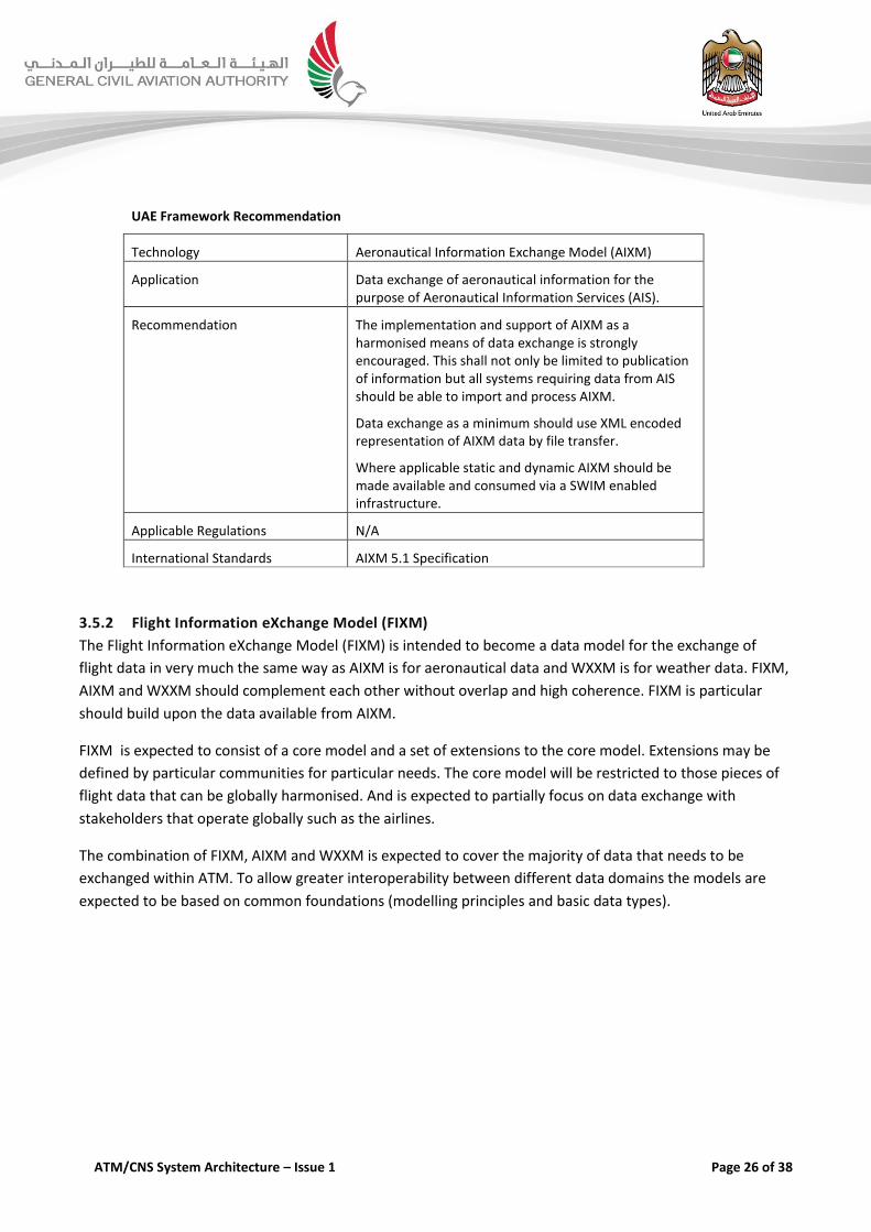
UAE Framework Recommendation
Technology Aeronautical Information Exchange Model (AIXM)
Application Data exchange of aeronautical information for the purpose of Aeronautical Information Services (AIS).
Recommendation The implementation and support of AIXM as a harmonised means of data exchange is strongly encouraged. This shall not only be limited to publication of information but all systems requiring data from AIS should be able to import and process AIXM.
Data exchange as a minimum should use XML encoded representation of AIXM data by file transfer.
Where applicable static and dynamic AIXM should be made available and consumed via a SWIM enabled infrastructure.
Applicable Regulations N/A
International Standards AIXM 5.1 Specification
3.5.2 Flight Information eXchange Model (FIXM)
The Flight Information eXchange Model (FIXM) is intended to become a data model for the exchange of
flight data in very much the same way as AIXM is for aeronautical data and WXXM is for weather data. FIXM,
AIXM and WXXM should complement each other without overlap and high coherence. FIXM is particular
should build upon the data available from AIXM.
FIXM is expected to consist of a core model and a set of extensions to the core model. Extensions may be
defined by particular communities for particular needs. The core model will be restricted to those pieces of
flight data that can be globally harmonised. And is expected to partially focus on data exchange with
stakeholders that operate globally such as the airlines.
The combination of FIXM, AIXM and WXXM is expected to cover the majority of data that needs to be
exchanged within ATM. To allow greater interoperability between different data domains the models are
expected to be based on common foundations (modelling principles and basic data types).
ATM/CNS System Architecture – Issue 1 Page 27 of 38
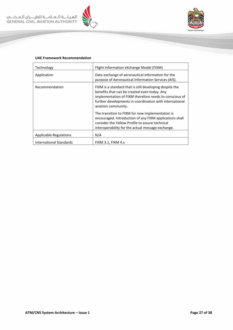
UAE Framework Recommendation
Technology Flight Information eXchange Model (FIXM)
Application Data exchange of aeronautical information for the purpose of Aeronautical Information Services (AIS).
Recommendation FIXM is a standard that is still developing despite the benefits that can be created even today. Any implementation of FIXM therefore needs to conscious of further developments in coordination with international aviation community.
The transition to FIXM for new implementation is encouraged. Introduction of any FIXM applications shall consider the Yellow Profile to assure technical interoperability for the actual message exchange.
Applicable Regulations N/A
International Standards FIXM 3.1, FIXM 4.x
ATM/CNS System Architecture – Issue 1 Page 28 of 38
4 Framework Requirements for Navigation
4.1 Introduction
Navigation infrastructures are an important backbone of Air Traffic Service (ATS) alongside communication
and surveillance systems. Navigation aids comprise legacy ground-based navigation aids such as Distance
Measuring Equipment (DME) and VHF Omni-directional Range (VOR) to satellite-based navigation aids such
as the Global Navigation Satellite System (GNSS).
Since the implementation of the Airspace Restructuring Project in 2017 Navigation infrastructure has to
support the Performance-Based Navigation (PBN) supporting RNAV 1 specification. PBN is a global set of
area navigation standards based on navigation performance and functionality required for the proposed
operation. PBN concept encompasses two types of navigation specifications:
RNAV Specification – Navigation specification based on area navigation that does not include the requirement
for on-board performance monitoring and alerting, e.g. RNAV 5, RNAV 2 and RNAV 1.
RNP Specification – Navigation specification based on area navigation that requires on-board performance
monitoring and alerting, e.g. RNP 4, RNP 2 and RNP APCH.
Within the Emirates FIR the following ground-based navigation aids are considered.
Distance Measuring Equipment (DME)
VHF Omni-directional Range (VOR)
Instrument Landing Systems (ILS)
4.2 Distance Measuring Equipment (DME)
DME is a ground-based navigation aids that helps the aircraft measure its distance from the DME station by
timing the propagation delay in the radio signals sent between the station and the aircraft. In area
navigation, the aircraft can use multiple DME signals to triangulate its position by utilizing multiple DME-
distance measurements and the published locations of the stations. Thus, DME can serve as a contingency
navigation aid supplementing GNSS and is also part of navigation infrastructure that supports PBN
operations down to RNAV1 specification.

ATM/CNS System Architecture – Issue 1 Page 29 of 38
UAE Framework Recommendation
Technology Distance Measuring Equipment (DME)
Application Ground Based Navigation Aid
Recommendation N/A
Applicable Regulations N/A
International Standards ICAO Annex 10 Volume I: Radio Navigation Aids
4.3 VHF Omni-directional Range (VOR)
VOR is a navigation aid that transmits VHF navigation signals 360° in azimuth angles. Using signal phase
measurement comparison, the aircraft with a VOR receiver can determine its radial from the VOR ground
station. When used in conjunction with a collocated DME and the published location of the station stored in
the on-board database, the aircraft can determine its coordinate location and thus conforming to RNAV-5
specification. Additionally, VOR frequency may also be used for ATIS delivery.
UAE Framework Recommendation
Technology VHF Omni-directional Range (VOR)
Application Ground Based Navigation Aid
Recommendation N/A
Applicable Regulations N/A
International Standards ICAO Annex 10 Volume I: Radio Navigation Aids
4.4 Instrument Landing System (ILS)
ILS is a navigation aid enabling precision approach and landing to a runway by a combination of horizontal
and vertical guidance. The horizontal guidance signal is transmitted from a localizer (LOC) while vertical
guidance signal is transmitted from a glide slope (GS); aircraft avionics process the information and present it
as course deviation indicator on cockpit Primary Flight Display (PFD).
Currently, the ILS is the primary technology that enables precision approaches down to Category III limits. It
is a proven technology that meets user requirements today and is still considered an essential navigation
system where precision approaches are required.

ATM/CNS System Architecture – Issue 1 Page 30 of 38
5 Framework Requirements for Surveillance
5.1 Introduction
Surveillance system provides the aircraft position and other related information to ATC and/or airborne
users. In essence the surveillance system used in ATC are sensors or communication links that provide
aircraft position information and include means of identification to allow ATC.
To allow the implementation of a surveillance-based separations, such as 3-NM or 5-NM, uninterruptible
and accurate surveillance needs to be provided. This can be achieved though having either a highly reliable
single layer of surveillance sensors or multiple-layers forming a single highly reliable service.
Using surveillance data processing systems information from several sensors is integrated and consolidated
to create a coherent positional information of all aircrafts, including current heading and speed information.
ATS surveillance systems can be classified in three categories, depending on how the aircraft signals are
received and processed by the ground sensors;
Independent Non-Cooperative Surveillance: The aircraft position is derived from measurement not using the
cooperation of the aircraft. An example is a Primary Surveillance Radar (PSR).
Independent Cooperative Surveillance: The position is derived from measurements performed by a local
surveillance subsystem using cooperative aircraft transmissions. The Secondary Surveillance Radar (SSR) is an
example of this category.
Dependent Cooperative Surveillance: Dependent Cooperative Surveillance derives the aircraft position using
subsystem on board the aircraft and the aircraft position is then provided to the local surveillance subsystem,
possibly along with additional data. Automatic Dependent Surveillance – Broadcast (ADS-B) is an example of
this category.
“Independent” or “Dependent” refers to how the aircraft position is measured; if it is from the ground it is
Independent, or if the aircraft position is determined on-board then it is Dependent.
“Cooperative” or “Non-Cooperative” Surveillance refers to the requirement of aircraft equipment; if
required, then it is Cooperative, if the surveillance does not require aircraft equipment then it is Non-
Cooperative.
Technologies and procedures used for ATS surveillance are varied. This framework addresses the following
technologies.
Primary Surveillance Radar (PSR)
Secondary Surveillance Radar (SSR) with Mode A, Mode C and Mode S
Multilateration (MLAT)
ATM/CNS System Architecture – Issue 1 Page 31 of 38
Automatic Dependent Surveillance – Broadcast (ADS-B).
Automatic Dependent Surveillance – Contract (ADS-C)
Primary Surveillance Radar (PSR)
Surface Movement Radar (SMR)
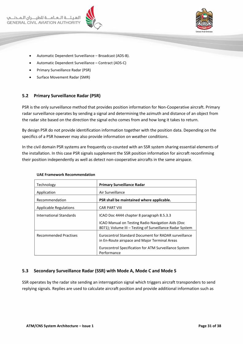
5.2 Primary Surveillance Radar (PSR)
PSR is the only surveillance method that provides position information for Non-Cooperative aircraft. Primary
radar surveillance operates by sending a signal and determining the azimuth and distance of an object from
the radar site based on the direction the signal echo comes from and how long it takes to return.
By design PSR do not provide identification information together with the position data. Depending on the
specifics of a PSR however may also provide information on weather conditions.
In the civil domain PSR systems are frequently co-counted with an SSR system sharing essential elements of
the installation. In this case PSR signals supplement the SSR position information for aircraft reconfirming
their position independently as well as detect non-cooperative aircrafts in the same airspace.
UAE Framework Recommendation
Technology Primary Surveillance Radar
Application Air Surveillance
Recommendation PSR shall be maintained where applicable.
Applicable Regulations CAR PART VIII
International Standards ICAO Doc 4444 chapter 8 paragraph 8.5.3.3
ICAO Manual on Testing Radio Navigation Aids (Doc 8071); Volume III – Testing of Surveillance Radar System
Recommended Practises Eurocontrol Standard Document for RADAR surveillance in En-Route airspace and Major Terminal Areas
Eurocontrol Specification for ATM Surveillance System Performance
5.3 Secondary Surveillance Radar (SSR) with Mode A, Mode C and Mode S
SSR operates by the radar site sending an interrogation signal which triggers aircraft transponders to send
replying signals. Replies are used to calculate aircraft position and provide additional information such as

ATM/CNS System Architecture – Issue 1 Page 32 of 38
identification and pressure-altitude reports. The “Mode” of the aircraft transponder determines the
information that is sent in response to the interrogation.
Conventional SSR radars commonly support only very limited information to be part of the reply that
includes a 12 bit code for identification (Mode A) and the barometric altitude (Mode C). The more modern
Mode S (Selective Addressing) will provide for aircraft equipped with Mode S transponders their permanent
and unique 24-bit ICAO address as well as additional information. For Mode S Elementary Surveillance (ELS)
this includes aircraft identity (e.g. call-sign), altitude (in 25ft intervals), transponder capability, flight status
(airborne or on-the-ground) and Surveillance Identifier (SI) code. It is important to note that Mode S radars
are still able to support Mode A and Mode C assuring that surveillance is also assured for non-Mode S
equipped aircraft.
Moreover, aircraft compliant with Mode S Enhanced Surveillance (EHS) provide the above ELS reporting
functionalities plus some or all of the following downlinked aircraft parameters (DAPs):
Selected Altitude - the flight level which is manually entered in the Flight Management System (FMS) by the
pilot.
Roll Angle, True Track Angle and Track Angle Rate - these parameters may be used to enhance the radar
tracking capability and/or tactical trajectory prediction by ATC systems.
Ground Speed - calculated aircraft speed relative to the ground.
Magnetic Heading - the aircraft heading relative to magnetic north.
Indicated airspeed (IAS) and Mach-number - Making this information available to ATCs supports separation
provision tasks, reduces the R/T and hence ATC workload.
Aircraft Vertical rate - barometric rate of climb / descent
Traffic Collision Avoidance System (TCAS) downlinked resolution advisories (RAs).
Within the UAE the use of Mode S is encouraged. Furthermore CAR PART IV required no foreign registered
operator of an aircraft fitted with ACAS II equipment shall undertake a flight unless equipped with a Mode S
transponder compliant with Annex 10, Volume IV within the EMIRATES FIR.
ATM/CNS System Architecture – Issue 1 Page 33 of 38
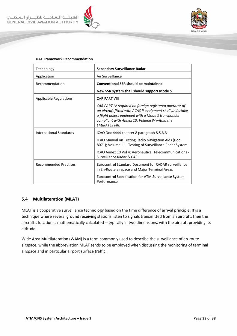
UAE Framework Recommendation
Technology Secondary Surveillance Radar
Application Air Surveillance
Recommendation Conventional SSR should be maintained
New SSR system shall should support Mode S
Applicable Regulations CAR PART VIII
CAR PART IV required no foreign registered operator of an aircraft fitted with ACAS II equipment shall undertake a flight unless equipped with a Mode S transponder compliant with Annex 10, Volume IV within the EMIRATES FIR.
International Standards ICAO Doc 4444 chapter 8 paragraph 8.5.3.3
ICAO Manual on Testing Radio Navigation Aids (Doc 8071); Volume III – Testing of Surveillance Radar System
ICAO Annex 10 Vol 4: Aeronautical Telecommunications - Surveillance Radar & CAS
Recommended Practises Eurocontrol Standard Document for RADAR surveillance in En-Route airspace and Major Terminal Areas
Eurocontrol Specification for ATM Surveillance System Performance
5.4 Multilateration (MLAT)
MLAT is a cooperative surveillance technology based on the time difference of arrival principle. It is a
technique where several ground receiving stations listen to signals transmitted from an aircraft; then the
aircraft's location is mathematically calculated -- typically in two dimensions, with the aircraft providing its
altitude.
Wide Area Multilateration (WAM) is a term commonly used to describe the surveillance of en-route
airspace, while the abbreviation MLAT tends to be employed when discussing the monitoring of terminal
airspace and in particular airport surface traffic.
ATM/CNS System Architecture – Issue 1 Page 34 of 38
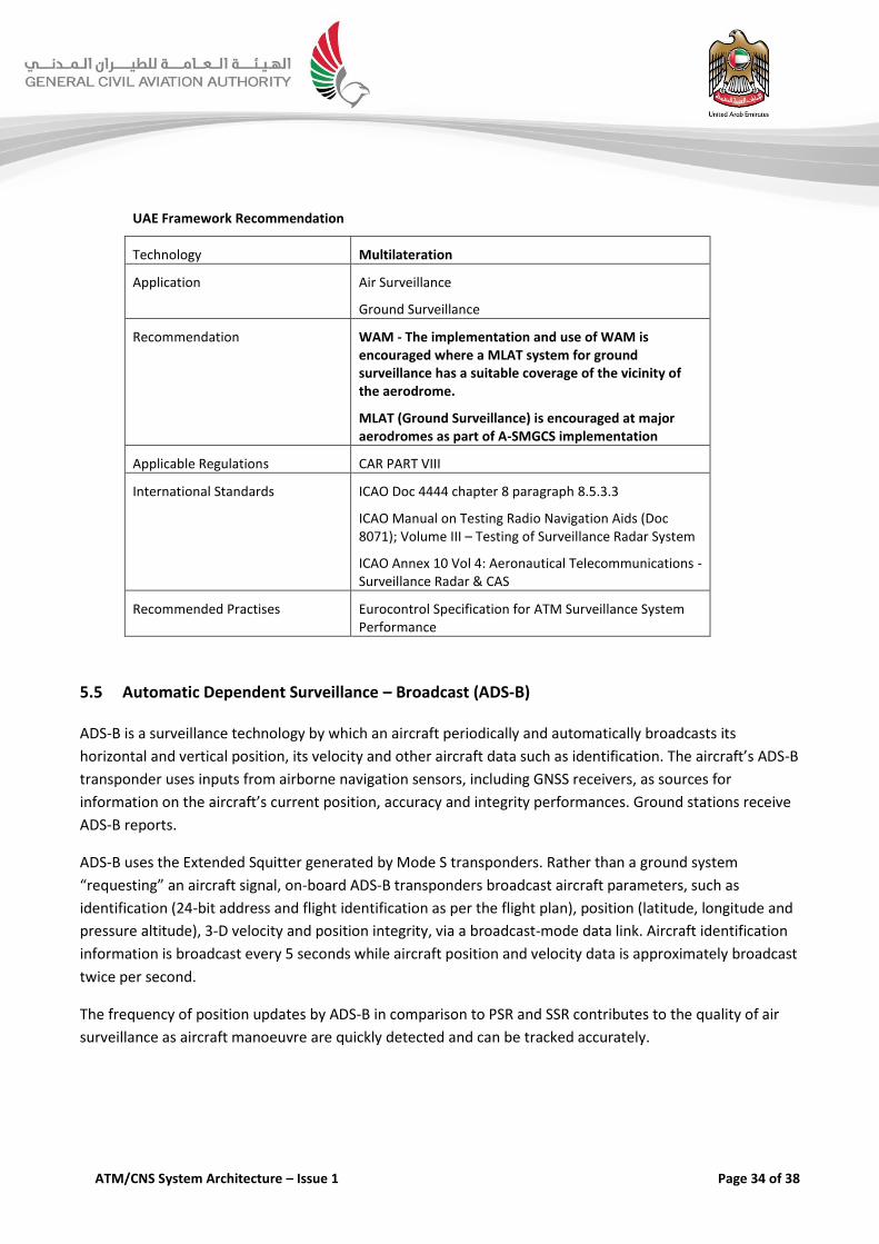
UAE Framework Recommendation
Technology Multilateration
Application Air Surveillance
Ground Surveillance
Recommendation WAM - The implementation and use of WAM is encouraged where a MLAT system for ground surveillance has a suitable coverage of the vicinity of the aerodrome.
MLAT (Ground Surveillance) is encouraged at major aerodromes as part of A-SMGCS implementation
Applicable Regulations CAR PART VIII
International Standards ICAO Doc 4444 chapter 8 paragraph 8.5.3.3
ICAO Manual on Testing Radio Navigation Aids (Doc 8071); Volume III – Testing of Surveillance Radar System
ICAO Annex 10 Vol 4: Aeronautical Telecommunications - Surveillance Radar & CAS
Recommended Practises Eurocontrol Specification for ATM Surveillance System Performance
5.5 Automatic Dependent Surveillance – Broadcast (ADS-B)
ADS-B is a surveillance technology by which an aircraft periodically and automatically broadcasts its
horizontal and vertical position, its velocity and other aircraft data such as identification. The aircraft’s ADS-B
transponder uses inputs from airborne navigation sensors, including GNSS receivers, as sources for
information on the aircraft’s current position, accuracy and integrity performances. Ground stations receive
ADS-B reports.
ADS-B uses the Extended Squitter generated by Mode S transponders. Rather than a ground system
“requesting” an aircraft signal, on-board ADS-B transponders broadcast aircraft parameters, such as
identification (24-bit address and flight identification as per the flight plan), position (latitude, longitude and
pressure altitude), 3-D velocity and position integrity, via a broadcast-mode data link. Aircraft identification
information is broadcast every 5 seconds while aircraft position and velocity data is approximately broadcast
twice per second.
The frequency of position updates by ADS-B in comparison to PSR and SSR contributes to the quality of air
surveillance as aircraft manoeuvre are quickly detected and can be tracked accurately.
ATM/CNS System Architecture – Issue 1 Page 35 of 38
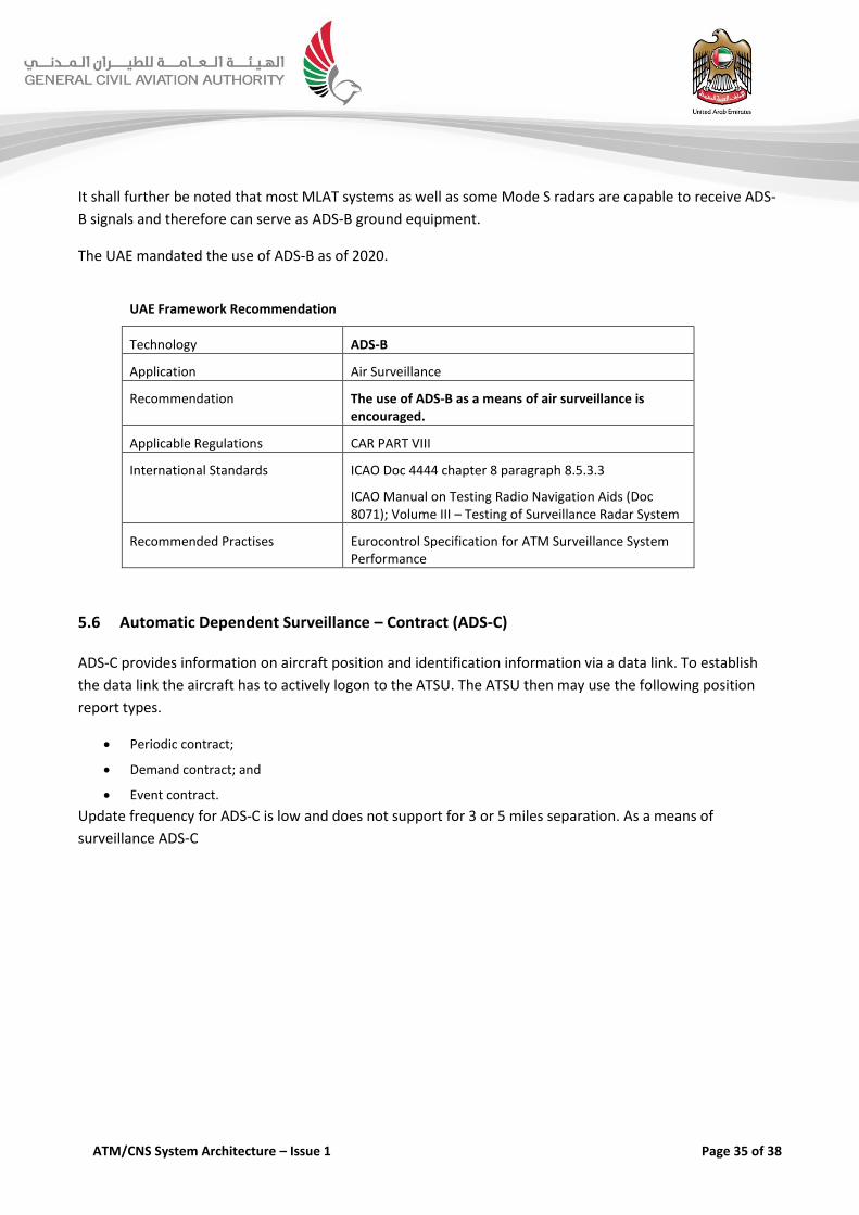
It shall further be noted that most MLAT systems as well as some Mode S radars are capable to receive ADS-
B signals and therefore can serve as ADS-B ground equipment.
The UAE mandated the use of ADS-B as of 2020.
UAE Framework Recommendation
Technology ADS-B
Application Air Surveillance
Recommendation The use of ADS-B as a means of air surveillance is encouraged.
Applicable Regulations CAR PART VIII
International Standards ICAO Doc 4444 chapter 8 paragraph 8.5.3.3
ICAO Manual on Testing Radio Navigation Aids (Doc 8071); Volume III – Testing of Surveillance Radar System
Recommended Practises Eurocontrol Specification for ATM Surveillance System Performance
5.6 Automatic Dependent Surveillance – Contract (ADS-C)
ADS-C provides information on aircraft position and identification information via a data link. To establish
the data link the aircraft has to actively logon to the ATSU. The ATSU then may use the following position
report types.
Periodic contract;
Demand contract; and
Event contract.
Update frequency for ADS-C is low and does not support for 3 or 5 miles separation. As a means of
surveillance ADS-C

ATM/CNS System Architecture – Issue 1 Page 36 of 38
UAE Framework Recommendation
Technology ADS-C
Application Air Surveillance
Recommendation Not recommended to be use as a means of surveillance in Emirates FIR. Surveillance is achieved a multi/layer surveillance coverage.
Applicable Regulations N/A
International Standards N/A
In most cases, the position source for ADS-C reports is GNSS. The information is displayed to ATC and can
also be used by automated flight tracking and monitoring systems. ADS-C reports are sent from the aircraft
to ATC via a VHF or satellite data link and include position, velocity, intent, and weather.
5.7 Surface Movement Radar (SMR)
Surface Movement Radar (SMR) is radar equipment specifically designed to detect all principal features on
the surface of an airport, including aircraft and vehicular traffic, and to present the entire image on a radar
indicator console in the control tower. It is used to augment visual observation by tower personnel of
aircraft and/or vehicular movements on runways and taxi-ways.
SMR and MLAT are typically the sensor technologies that used to implement A-SMGCS systems including
dedicated tools and safety nets.
ICAO defines 4 levels of A-SMGCS implementation based on a complexity and traffic density approach:
A-SMGCS Level 1 (improved Surveillance) makes use of improved surveillance and procedures, covering the
manoeuvring area for ground vehicles and the movement area for aircraft. The procedures concern
identification and the issuance of ATC instructions and clearances. The controllers are given traffic position and
identity information which is an important step forward from the traditional Surface Movement Radar (SMR)
image.
A-SMGCS Level 2 (Surveillance + Safety Nets) adds safety nets which protect runways and designated areas
and the associated procedures. Appropriate alerts are generated for the controllers in case of conflicts
between all vehicles on runways and the incursion of aircraft onto designated restricted areas.
A-SMGCS Level 3 (Conflict Detection) involves the detection of all conflicts on the movement area as well as
improved guidance and planning for use by controllers.
A-SMGCS Level 4 (Conflict Resolution, Automatic Planning & Guidance) provides resolutions for all conflicts
and automatic planning and automatic guidance for the pilots as well as the controllers.

ATM/CNS System Architecture – Issue 1 Page 37 of 38
UAE Framework Recommendation
Technology Surface Movement Radar (SMR)
Application Ground Surveillance
Recommendation The use of SMR highly contributes to the work of the ATC tower contributing to the situational awareness. In combination with an A-SMGCS this increases efficiency and safety.
Applicable Regulations N/A
International Standards N/A
5.8 Surveillance Data Sharing
Most surveillance sensor system provide substantially better operational coverage than actually required.
This may result supported sensor range or vertical coverage. As a consequence the sensor provides coverage
of airspace controlled by an adjacent ATSU that may use the surveillance data to enhance the overall
surveillance performance in their airspace.
The sharing of Surveillance Data is made available to complement and enhance the quality of the individual
air situation picture used by the ATSU. The sharing of surveillance data a common practise in many areas of
the world. By sharing the surveillance data between adjacent Air Traffic Service units and fusing the data in
locally integrated air situation pictures are enhanced.
To allow for easy data exchange surveillance data shall use the manufacture independent ASTERIX encoding
that fully supports the exchange of multiple data streams for radar, ADS B, Multilateration, Weather Radar
and processed air situation pictures together with associated and supplemental information.
For Surveillance Data sharing the ATSUs have to establish respective service levels in particular with respect
to performance and quality criteria.

ATM/CNS System Architecture – Issue 1 Page 38 of 38
UAE Framework Recommendation
Technology Surveillance Data Sharing
Application Air Surveillance
Recommendation Data Sharing needs to be supported by respective service level agreements that assures that surveillance performance
Eurocontrol Guidelines for an agreement for the shared use of radar sensor data.and availability meets the minimal.
Applicable Regulations N/A
International Standards N/A
=== END OF DOCUMENT ===