Embed Size (px)
Citation preview

DOT/FAA/TC-18/22 Federal Aviation Administration William J. Hughes Technical Center Aviation Research Division Atlantic City International Airport New Jersey 08405
Performance Assessment of the Vestas InteliLight™ X-Band System as an Aircraft Detection Lighting System (ADLS) James Patterson, Jr. July 2018 Final Report This document is available to the U.S. public through the National Technical Information Services (NTIS), Springfield, Virginia 22161. This document is also available from the Federal Aviation Administration William J. Hughes Technical Center at actlibrary.tc.faa.gov.
U.S. Department of Transportation Federal Aviation Administration

NOTICE
This document is disseminated under the sponsorship of the U.S. Department of Transportation in the interest of information exchange. The United States Government assumes no liability for the contents or use thereof. The United States Government does not endorse products or manufacturers. Trade or manufacturer's names appear herein solely because they are considered essential to the objective of this report. The findings and conclusions in this report are those of the author(s) and do not necessarily represent the views of the funding agency. This document does not constitute FAA policy. Consult the FAA sponsoring organization listed on the Technical Documentation page as to its use. This report is available at the Federal Aviation Administration William J. Hughes Technical Center’s Full-Text Technical Reports page: actlibrary.tc.faa.gov in Adobe Acrobat portable document format (PDF).
Technical Documentation Page 1. Report No.
DOT/FAA/TC-18/22 2. Government Accession No. 3. Recipient's Catalog No.
4. Title and Subtitle
PERFORMANCE ASSESSMENT OF THE VESTAS INTELILIGHT™ X-BAND SYSTEM AS AN AIRCRAFT DETECTION LIGHTING SYSTEM (ADLS)
5. Report Date July 2018
6. Performing Organization Code ANG-E261
7. Author(s) James Patterson, Jr.* and Garrison Canter**
8. Performing Organization Report No.
9. Performing Organization Name and Address 10. Work Unit No. (TRAIS) * Federal Aviation Administration **SRA International, Inc. William J. Hughes Technical Center A CSRA Company Aviation Research Division 1201 New Road Airport Technology R&D Branch Suite 242 Atlantic City International Airport, NJ 08405 Linwood, NJ 08221
11. Contract or Grant No.
12. Sponsoring Agency Name and Address
U.S. Department of Transportation Federal Aviation Administration Airport Engineering Division 800 Independence Avenue SW Washington, DC 20591
13. Type of Report and Period Covered Final Report
14. Sponsoring Agency Code AAS-100
15. Supplementary Notes
Mike DiPilato (FAA Airport Technology Research and Development Branch) and Bill Kieffer (FAA Obstruction Evaluation Group) provided technical knowledge and support for this performance assessment. 16. Abstract Federal Aviation Administration (FAA) Airport Technology Research and Development Branch (ATR) personnel conducted performance assessments of the Vestas InteliLight™ X-band System. The purpose of these assessments was to determine if the Vestas InteliLight X-band system meets the aircraft detection lighting system (ADLS) requirements specified in Chapter 14 of FAA Advisory Circular (AC) 70/7460-1L, “Obstruction Marking and Lighting.” FAA ATR personnel conducted an initial performance assessment of the Vestas InteliLight X-band system at the Braderup Wind Park, located near Braderup, Germany. This performance assessment, which consisted of demonstrations, flight testing, and data analysis, was conducted on September 20, 2016. At the time of that performance assessment, the X-band version of the Vestas InteliLight system was not yet approved for operation in the United States. The X-band system received approval from the Federal Communications Commission (FCC) and FAA Spectrum Office on January 11, 2017. Therefore, on October 11, 2017, FAA ATR personnel conducted a follow-up assessment of the Vestas InteliLight X-band system installed at the Hancock Wind Project in Hancock County, Maine to validate the findings of the earlier assessment. At both the Braderup and Hancock sites, a series of flight patterns were flown against the Vestas InteliLight X-band system to demonstrate whether it could meet the FAA performance requirements specified in AC 70/7460-1L. In both assessments, the Vestas InteliLight X-band system performed according to the manufacturer’s specifications and met the performance requirements identified in AC 70/7460-1L. 17. Key Words
Aircraft detection lighting system (ADLS), Obstruction lighting, Vestas InteliLight™ system
18. Distribution Statement
This document is available to the U.S. public through the National Technical Information Service (NTIS), Springfield, Virginia 22161. This document is also available from the Federal Aviation Administration William J. Hughes Technical Center at actlibrary.tc.faa.gov.
19. Security Classif. (of this report) Unclassified
20. Security Classif. (of this page) Unclassified
21. No. of Pages 75
22. Price
Form DOT F 1700.7 (8-72) Reproduction of completed page authorized.
iii
TABLE OF CONTENTS
Page
EXECUTIVE SUMMARY ix
1. INTRODUCTION 1
1.1 Purpose 1 1.2 Background 1 1.3 Objective 2 1.4 Related Documentation 3
2. THE ADLS STANDARDS 4
3. VESTAS INTELILIGHT SYSTEM CHARACTERISTICS AND SPECIFICATIONS 7
3.1 Vestas InteliLight System Operational Description 8 3.2 Vestas InteliLight System Radar Unit Description 9 3.3 Vestas InteliLight ALC Description 10 3.4 Vestas ICC Description 10 3.5 Vestas InteliLight System Perimeters 11 3.6 Vestas InteliLight System Fail-Safe Design 11
4. VESTAS INTELILIGHT SYSTEM INSTALLATION DESCRIPTIONS 13
4.1 Description of the Braderup Wind Park Installation 13 4.2 Description of the Hancock Wind Project Installation 17
5. THE FAA ASSESSMENTS OF THE VESTAS INTELILIGHT SYSTEM 22
5.1 The FAA Assessment of the Vestas InteliLight System at the Braderup Wind Park 22
5.1.1 The FAA Flight Assessment 22 5.1.2 The FAA Component Failure Assessment 23
5.2 The FAA Assessment of the Vestas InteliLight System at the Hancock Wind
Project 24
5.2.1 The FAA Flight Assessment 24 5.2.2 The FAA Component Failure Assessment 26
6. THE RESULTS OF THE FAA ASSESSMENTS 26
6.1 Results of the Assessment at the Braderup Wind Park 26

iv
6.1.1 Basic Function Assessment 26 6.1.2 Detection Performance Assessment 27 6.1.3 Component Failure Assessment 46
6.2 Results of the Assessment at the Hancock Wind Project 47
6.2.1 Basic Function Assessment 47 6.2.2 Detection Performance Assessment 48 6.2.3 Component Failure Assessment 59
7. CONCLUSIONS 59
8. REFERENCES 59
APPENDICES
A—Advisory Circular 70/7460-1L, Chapter 14, Aircraft Detection Lighting Systems B—Vestas InteliLight™ System Information

v
LIST OF FIGURES
Figure Page
1 Required ADLS Detection Coverage 6
2 Vestas InteliLight Systems Overview Diagram 8
3 Vestas InteliLight Radar Mounted on a Wind Turbine 9
4 Vestas InteliLight Warning Zone Perimeter for a Wind Farm Application 11
5 Braderup Wind Park Location 13
6 Wind Turbines at the Braderup Wind Park 14
7 Map Showing Ground Clutter Around the Braderup Wind Park 14
8 Vestas InteliLight System Installation at the Braderup Wind Park 15
9 Vestas InteliLight Radar Position 16
10 Radar Interface Monitored During Assessment 16
11 Camera Feed Used to Monitor Obstruction Light Status During Braderup Assessment 17
12 Hancock Wind Project Location 18
13 Map Showing Bull Hill Wind Turbines in Relation to Hancock Wind Project 18
14 Hancock and Bull Hill Turbines 19
15 Example of Radar Installed at Hancock Wind Project 20
16 Map Showing Radar Locations at Hancock Wind Project 20
17 Radar Interface Monitored During Assessment 21
18 Webcam Used to Monitor Obstruction Light Status During Assessment 21
19 Cessna 172 Used for Braderup Assessment 23
20 The GPS Flight Track Data From the Aircraft: Braderup Assessment 23
21 The GPS Flight Track Data From the Aircraft: Hancock Assessment 25
22 Vestas InteliLight System Cumulative Radar Tracks (Dark Blue) Overlaid on the FAA Aircraft’s GPS Tracks (Light Blue) 27
vi
23 Flight Directly to and Over the Wind Turbine Farm at 800 ft AGL From the Northwest (Events 1-4) 30
24 Flight Directly to and Over the Wind Turbine Farm at 800 ft AGL From the West (Events 5-8) 31
25 Flight Directly to and Over the Wind Turbine Farm at 800 ft AGL From the East (Events 9-12) 32
26 Flight Adjacent to Wind Turbine Farm at 800 ft AGL From the Southeast (Events 13-16) 33
27 Flight Adjacent to Wind Turbine Farm at 800 ft AGL From the East (Events 17-20) 34
28 Continuation of Flight Adjacent to Wind Turbine Farm at 800 ft AGL From the East (Events 21 and 22) 35
29 Flight Directly Through the Warning Zone at 1500 ft AGL (Events 23-26) 36
30 Flight Directly Through the Warning Zone at 2000 ft AGL (Events 27-30) 37
31 Circling Flight Over the Wind Turbine Farm at 800 ft AGL, Exiting to the Northwest (Events 31-34) 38
32 Continuation of Circling Flight Over the Wind Turbine Farm at 800 ft AGL, Exiting to the Northwest (Events 35 and 36) 39
33 Circling Flight Over the Wind Turbine Farm Descending From 3000 to 1500 ft AGL (Events 37-40) 40
34 Circling Flight Over the Wind Turbine Farm Descending From 3000 to 1500 ft AGL (Events 41 and 42) 41
35 Flight Along the Warning Zone Perimeter at 800 ft AGL (Events 43-46) 42
36 Descending Flight Into the Warning Zone (Events 47-50) 43
37 Flight to the Wind Turbine Farm With Aircraft Initially Hidden in Radar Shadow (Events 51-54) 44
38 Continuation of Flight to the Wind Turbine Farm With Aircraft Initially Hidden in Radar Shadow (Events 55 and 56) 45
39 Vestas InteliLight System Cumulative Radar Tracks (Yellow) Overlaid on the FAA Aircraft’s GPS Tracks (Light Blue) 47
40 Flight Directly to and Over the Wind Turbine Farm at 2300 ft MSL From the West (Events 1-4) 50

vii
41 Continuation of Flight Directly to and Over the Wind Turbine Farm at 2300 ft MSL From the West (Events 5 and 6) 51
42 Flight Directly to and Over the Wind Turbine Farm at 1500 ft MSL From the Northeast (Events 7-10) 52
43 Flight Directly to and Over the Wind Turbine Farm at 1200 ft MSL From the South (Events 11-14) 53
44 Circling Flight Over the Wind Turbine Farm at 1700 ft MSL, Exiting to the West (Events 15-18) 54
45 Continuation of Circling Flight Over the Wind Turbine Farm at 1700 ft MSL, Exiting to the West (Events 19 and 20) 55
46 Descending Flight Into the Warning Zone (Events 21-24) 56
47 Flight Along the Warning Zone Perimeter at 1200 ft MSL (Events 25-28) 57
48 Descending Circling Flight Over the Wind Turbine Farm Exiting to the West (Events 29-32) 58

viii
LIST OF ACRONYMS
AC Advisory Circular ADLS Aircraft detection lighting system AGL Above ground level ALC Aviation light controller ATR Airport Technology Research and Development Branch CFR Code of Federal Regulations FAA Federal Aviation Administration FCC Federal Communications Commission GPS Global positioning system ICC InteliLight™ Control Center MHz Megahertz MLC Master light controller MSL Mean sea level LAN Local area network NM Nautical mile SFG Sportfluggruppe Leck Air Base U.S. United States

ix/x
EXECUTIVE SUMMARY
Federal Aviation Administration (FAA) Airport Technology Research and Development Branch (ATR) personnel conducted performance assessments of the Vestas InteliLight™ X-band system. The purpose of these assessments was to determine if the Vestas InteliLight X-band system meets the aircraft detection lighting system (ADLS) requirements specified in Chapter 14 of FAA Advisory Circular (AC) 70/7460-1L, “Obstruction Marking and Lighting.” ADLSs continuously monitor the airspace around an obstruction or group of obstructions for aircraft; and when the detection system detects an aircraft in its airspace, the system sends an electronic signal to the lighting control unit, which turns on the lights. Once the aircraft clears the obstruction area and there is no longer a risk of collision, the detection system turns off the lights, and the system returns to standby mode. The United States (U.S.) has experienced a steady increase in the number of applications for construction of telecommunication towers and wind turbines. Any temporary or permanent structure, including telecommunication towers and wind turbines, that exceeds an overall height of 200 feet (61 meters) above ground level or exceeds any obstruction standard contained in Title 14 Code of Federal Regulations Part 77, “Safe, Efficient Use, and Preservation of the Navigable Airspace,” should be marked and/or lighted with FAA-approved paint markings or lighting fixtures to ensure that they are visible to pilots at night. Due to the number of existing telecommunication towers and wind turbines, combined with expected future construction, the number of obstructions that have these required lighting fixtures has greatly increased. As a result, it has created a light pollution nuisance to residents living near these obstructions. Using an ADLS could have a positive impact on this problem, while still providing a sufficient level of safety for pilots operating at night in the vicinity of these obstructions. FAA ATR personnel conducted an initial performance assessment of the Vestas InteliLight X-band system at the Braderup Wind Park, located near Braderup, Germany. This performance assessment, which included demonstrations, flight testing, and data analysis, was conducted on September 20, 2016. At the time of the performance assessment, the X-band version of the Vestas InteliLight system was not approved for operation in the U.S. The X-band system received approval from the Federal Communications Commission (FCC) and FAA Spectrum Office on January 11, 2017. Therefore, on October 11, 2017, FAA ATR personnel conducted a follow-up assessment of the Vestas InteliLight X-band system installed at the Hancock Wind Project in Hancock County, Maine to validate the findings of the earlier assessment. At both the Braderup and Hancock sites, a series of flight patterns were flown against the Vestas InteliLight X-band system to demonstrate whether it could meet the FAA performance requirements specified in AC 70/7460-1L. In both assessments, the Vestas InteliLight X-band system performed according to the manufacturer’s specifications and met the performance requirements identified in AC 70/7460-1L.

1
1. INTRODUCTION.
1.1 PURPOSE.
Federal Aviation Administration (FAA) Airport Technology Research and Development Branch (ATR) personnel conducted performance assessments of an X-band aircraft detection lighting system (ADLS) developed by Vestas®, referred to herein as the Vestas InteliLight™ system. The purpose of this assessment was to determine if the Vestas InteliLight system meets the ADLS requirements specified in Chapter 14 of FAA Advisory Circular (AC) 70/7460-1L, “Obstruction Marking and Lighting” [1]. 1.2 BACKGROUND.
In recent years, several companies have developed detection systems that monitor the airspace around an obstruction or group of obstructions to automatically turn the obstruction lighting on or off as needed. Such systems continuously monitor the airspace around their location; and when the detection system detects an aircraft in its airspace, the system sends an electronic signal to the lighting control unit, which turns on the lights. Once the aircraft clears the obstruction area and there is no longer a risk of collision, the ADLS turns off the lights, and the system returns to standby mode. These detection systems are typically (1) mounted directly on the obstruction, (2) positioned on a dedicated tower close to the obstruction, or (3) mounted on a stand-alone structure located in the vicinity of the obstruction at an optimized vantage point to ensure that the sensor can cover the entire volume of airspace around the obstruction. In addition to controlling the obstruction lighting, some vendors have suggested using supplemental warning tools, such as an audible warning message or supplemental lighting to alert the pilot, thereby providing an additional warning to the pilot that the aircraft is in close proximity to an obstruction. The United States (U.S.) has experienced a steady increase in the number of applications for construction of telecommunication towers and wind turbines, partially because of government mandates to improve the nation’s emergency communication network and to increase the amount of renewable energy generation. These telecommunication towers and wind turbines have become prominent throughout the U.S. Projections show that the accelerated rate of construction will continue well into the next decade. Any temporary or permanent structure, including these telecommunication towers and wind turbines, that exceeds an overall height of 200 feet (ft) (61 meters (m)) above ground level (AGL) or exceeds any obstruction standard contained in Title 14 Code of Federal Regulations (14 CFR) Part 77, “Safe, Efficient Use, and Preservation of the Navigable Airspace” [2], should be marked and/or lighted with FAA-approved paint markings or lighting fixtures to ensure that they are visible to pilots. Due to the number of existing telecommunication towers and wind turbines, combined with the expected construction of new structures, the number of obstructions that have FAA-required light fixtures has greatly increased. As a result, it has created a light pollution nuisance to residents living near these obstructions. Using an ADLS could mitigate this problem, while still providing a sufficient level of safety for pilots operating at night in the vicinity of these obstructions. From 2011 to 2015, ATR personnel have worked closely with several ADLS vendors to better understand the technologies, their capabilities, and the level of performance that is necessary to

2
safely integrate this concept into the National Airspace System. A major milestone achieved during the ADLS standards development was to enable the sensors to detect aircraft beyond the required 3 nautical miles (NM) from the obstruction, which would ensure that the lighting was on and that the pilot was able to visually acquire the lights 3 NM away from the obstruction. The 3-NM visibility requirement is important because it ties directly to the inflight visibility requirements for a flight conducted under Visual Flight Rules. In 2013, ATR personnel first developed standards for ADLS that were based on technical reviews, discussions, and flight tests of ADLS in the U.S. and Canada. The FAA has since used these ATR-developed standards as the baseline against which new ADLSs, such as the Vestas InteliLight system, were tested. The ATR-developed standards have since been integrated into AC 70/7460-1L as Chapter 14, “Aircraft Detection Lighting Systems,” which was published in December 2015 [1]. As of September 20, 2016, the date of the performance assessment, the Vestas InteliLight System (X-band radar unit) was not approved for operation in the U.S. It was approved for use in Europe, but approval was not received from the Federal Communications Commission (FCC) and FAA Spectrum Office until January 11, 2017. Vestas initially approached the FAA with an earlier version of the InteliLight System that used an L-band radar for detection but was denied approval of their application because of an initiative called the “500 MHz Initiative.” This initiative is described in
…a 2010 Presidential Memorandum which directed the Secretary of Commerce, working through the National Telecommunications and Information Administration, to collaborate with the FCC to make available a total of 500 megahertz (MHz) of Federal and nonfederal spectrum over the next 10 years for mobile and fixed wireless broadband use. [3]
Vestas L-band radar frequency was directly on the edge of the frequency band being vacated to support the initiative, so it could not be allowed. Vestas approached FAA researchers and explained that they could support a performance assessment of an alternative X-band radar that is approved for use in Europe, but the assessment would have to take place in Europe. FAA researchers agreed with their proposal to conduct the assessment in Europe; Vestas then planned and coordinated the details to install their system at a wind farm in Braderup, Germany. The FAA agreed to this proposal with the caveat that if Vestas receives approval for their X-band, or a derivative of it, to be operated in the U.S., researchers would need to conduct another brief system flight test here in the U.S. to confirm that it performs equal to or better than the system assessed in Germany. The X-band system received approval from the FCC and FAA Spectrum Office on January 11, 2017. Therefore, on October 11, 2017, FAA ATR personnel conducted a follow-up assessment of the Vestas InteliLight system installed at the Hancock Wind Project in Hancock County, Maine to validate the findings of the earlier assessment. 1.3 OBJECTIVE.
The primary objective of this assessment was to conduct a performance assessment of the Vestas InteliLight system according to the requirements and standards for ADLSs in Chapter 14 of

3
AC 70/7460-1L [1]. This report describes performance assessments of the Vestas InteliLight System installed in Braderup Germany and Hancock, ME. 1.4 RELATED DOCUMENTATION.
The guidelines in place for obstruction marking and lighting have remained mostly unchanged for the last 10 to 20 years and have proved to be sufficient for warning pilots of the presence of an obstruction. The recent update of AC 70/7460-1L does, however, include new material that is designed to improve safety, and at the same time, attempts to reduce the impact of obstruction lighting on nearby communities and wildlife. The introduction of ADLS suggests that the traditional obstruction lights remain the same in intensity, flash rate, and performance, but that the lights can be controlled by an automatic radar-activated monitoring system. The following FAA documents provide a significant amount of information and guidance pertaining to the lighting of obstructions: • AC 70/7460-1L, “Obstruction Marking and Lighting.”
This document specifically describes the various requirements for lighting and marking man-made structures as obstructions, and in its most recent update, now contains specific language on the performance standards for an ADLS.
• AC 150/5345-43, “Specification for Obstruction Lighting Equipment.”
This document specifies the lighting equipment and fixtures that should be used for lighting obstructions. The color of the light, flash rate, intensity, and various electrical and performance requirements are addressed in this document. Obstruction lights are given “L” type designations, which are described in this AC. The performance characteristics for the particular lights mentioned in this assessment are as follows:
- L-864—Red flashing obstruction light, 2000-peak candela, a minimum
750 candela, with a 3-degree vertical beam spread, flashing at a rate between 20 and 40 flashes per minute. This light is required on wind turbines.
• 14 CFR Part 77, “Safe, Efficient Use, and Preservation of the Navigable Airspace.”
This document addresses how to determine whether objects on the earth’s surface constitute an obstruction to air navigation, and thus, must either be prohibited or, at least, suitably marked and lighted as an obstruction.

4
• FAA Technical Note DOT/FAA/TC-TN12/9, “Evaluation of New Obstruction Lighting Techniques to Reduce Avian Fatalities,” James Patterson, Jr., May 2012. This document describes research conducted by FAA ATR personnel wherein researchers evaluated a proposal to omit or flash the normally steady-burning red obstruction lights as a way to mitigate their impact on birds, due to their unique color and flash pattern.
• FAA Technical Note DOT/FAA/TC-TN15/54, “Performance Assessment of the Laufer Wind Aircraft Detection System as an Aircraft Detection Lighting System,” James Patterson, Jr., May 2016. This document describes a prior research effort conducted by FAA ATR personnel to assess an ADLS and validate the draft performance standards that were proposed for these types of systems.
• FAA Technical Note DOT/FAA/TC-TN16/41, “Performance Assessment of the Terma Obstruction Light Control System as an Aircraft Detection Lighting System,” James Patterson, Jr., June 2016. This document describes a subsequent research effort by FAA ATR personnel to assess an additional ADLS to determine if it met the AC 70/7460-1L standards.
• FAA Interim Report DOT/FAA/TC-TN17/30, “Performance Assessment of the Vestas InteliLight™ System as an Aircraft Detection Lighting System,” James Patterson, Jr., June 2017. This interim report describes the initial assessment of the Vestas InteliLight System by FAA ATR personnel at the Braderup Wind Park in 2016 and forms the basis for the final report.
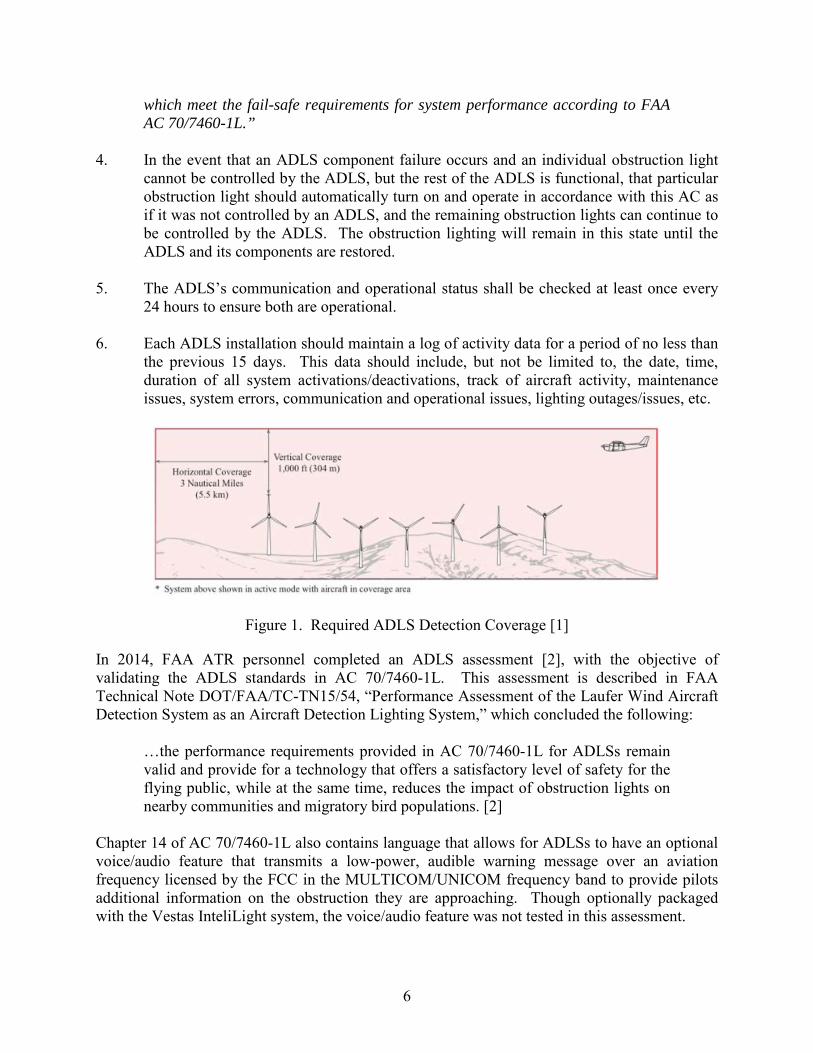
2. THE ADLS STANDARDS.
Based on the result of research efforts conducted by FAA ATR personnel, Chapter 14 of AC 70/7460-1L is the first fully comprehensive set of standards for ADLSs published worldwide [1]. Earlier research efforts in Canada and the U.S. led to the development of a few sets of very ambiguous, vague descriptions of the technology, but they did not provide any specific guidance on the required range, coverage area, detection target size, or operational requirements for the technology. The following are the key ADLS operational requirements introduced in Chapter 14 of AC 70/7460-1L [1]. Chapter 14, in its entirety, is included in appendix A.
1. The system should be designed with sufficient sensors to provide complete detection
coverage for aircraft that enter a three-dimensional volume of airspace, or coverage area, around the obstruction(s) (see figure 1), as follows:

5
a. Horizontal detection coverage should provide for obstruction lighting to be activated and illuminated prior to aircraft penetrating the perimeter of the volume, which is a minimum of 3 NM (5.5 km) away from the obstruction or the perimeter of a group of obstructions.
b. Vertical detection coverage should provide for obstruction lighting to be activated and illuminated prior to aircraft penetrating the volume, which extends from the ground up to 1000 feet (304 m) above the highest part of the obstruction or group of obstructions, for all areas within the 3-NM (5.5-km) perimeter defined above.
2. The ADLS should activate the obstruction lighting system in sufficient time to allow the lights to illuminate and synchronize to flash simultaneously prior to an aircraft penetrating the volume defined above. The lights should remain on for a specific time period, as follows:
a. For ADLSs capable of continuously monitoring aircraft while they are within
the 3-NM/1000-foot (5.5-km/304-m) volume, the obstruction lights should stay on until the aircraft exits the volume. In the event detection of the aircraft is lost while being continuously monitored within the 3-NM/1000-foot (5.5-km/304-m) volume, the ADLS should initiate a 30-minute timer and keep the obstruction lights on until the timer expires. This should provide the untracked aircraft sufficient time to exit the area and give the ADLS time to reset.
b. For ADLSs without the capability of monitoring aircraft targets in the
3-NM/1000-foot (5.5-km/304-m) volume, the obstruction lights should stay on for a preset amount of time, calculated as follows: i. For single obstructions: 7 minutes.
ii. For groups of obstructions: (the widest dimension in nautical miles + 6) x 90 seconds equals the number of seconds the light(s) should remain on.
3. In the event of an ADLS component or system failure, the ADLS should automatically
turn on all the obstruction lighting and operate in accordance with this AC as if it was not controlled by an ADLS. The obstruction lighting must remain in this state until the ADLS and its components are restored. Special Note: As part of the Notice of Proposed Construction or Alteration (FAA Form 7460) filing process, the vendor must provide the FAA with a clear, acceptable explanation of how a component or system failure will be identified and addressed, and must also explain how possible interference will be identified and addressed. A statement such as the following should also be included verifying that the mitigation, monitoring, and fail-safe requirements provided in AC 7460-1L are being met: “With regards to system component/system failure and interference of the radar signal, <insert vendor name> incorporates mitigation and monitoring systems
6
which meet the fail-safe requirements for system performance according to FAA AC 70/7460-1L.”
4. In the event that an ADLS component failure occurs and an individual obstruction light
cannot be controlled by the ADLS, but the rest of the ADLS is functional, that particular obstruction light should automatically turn on and operate in accordance with this AC as if it was not controlled by an ADLS, and the remaining obstruction lights can continue to be controlled by the ADLS. The obstruction lighting will remain in this state until the ADLS and its components are restored.
5. The ADLS’s communication and operational status shall be checked at least once every
24 hours to ensure both are operational. 6. Each ADLS installation should maintain a log of activity data for a period of no less than
the previous 15 days. This data should include, but not be limited to, the date, time, duration of all system activations/deactivations, track of aircraft activity, maintenance issues, system errors, communication and operational issues, lighting outages/issues, etc.
Figure 1. Required ADLS Detection Coverage [1]
In 2014, FAA ATR personnel completed an ADLS assessment [2], with the objective of validating the ADLS standards in AC 70/7460-1L. This assessment is described in FAA Technical Note DOT/FAA/TC-TN15/54, “Performance Assessment of the Laufer Wind Aircraft Detection System as an Aircraft Detection Lighting System,” which concluded the following:
…the performance requirements provided in AC 70/7460-1L for ADLSs remain valid and provide for a technology that offers a satisfactory level of safety for the flying public, while at the same time, reduces the impact of obstruction lights on nearby communities and migratory bird populations. [2]
Chapter 14 of AC 70/7460-1L also contains language that allows for ADLSs to have an optional voice/audio feature that transmits a low-power, audible warning message over an aviation frequency licensed by the FCC in the MULTICOM/UNICOM frequency band to provide pilots additional information on the obstruction they are approaching. Though optionally packaged with the Vestas InteliLight system, the voice/audio feature was not tested in this assessment.

7
3. VESTAS INTELILIGHT SYSTEM CHARACTERISTICS AND SPECIFICATIONS.
The Vestas InteliLight is a radar-based system following the general description provided in Chapter 14 of AC 70/7460-1L. The system is designed to actively keep obstruction lights turned off when aircraft are undetected in the vicinity of the obstruction or group of obstructions. The obstruction lights default setting is to remain powered on unless an “active off” signal is received from the Vestas InteliLight system, ensuring safety in the event of a system interruption. As an aircraft is detected entering the predefined perimeter around the obstruction(s), the Vestas InteliLight system activates (turns on) all required obstruction lights. The obstruction lights remain on until all aircraft have been tracked leaving the warning zone perimeter and countdown timers for aircraft with missing radar tracks have expired. Throughout operation, Vestas InteliLight system status is continuously monitored to deliver end-to-end (i.e., aircraft detection-to-obstruction light illumination) aviation safety control. Appendix B contains additional information provided by Vestas regarding the Vestas InteliLight system. Figure 2 shows an overview of the Vestas InteliLight system concept for a wind turbine installation. The primary components of the Vestas InteliLight system consist of the radar unit(s), aviation light controller (ALC), and Vestas InteliLight Control Center (ICC).

8
Figure 2. Vestas InteliLight Systems Overview Diagram [4]
3.1 VESTAS INTELILIGHT SYSTEM OPERATIONAL DESCRIPTION.
The Vestas InteliLight system operates as follows [4]:
1. The Vestas InteliLight system radar(s) detect and track all aircraft within a minimum range of 4.32 NM (8 km), while keeping the obstruction lights in “actively off” mode. This means that a constant “lights off” signal is required by the lights to remain off.
2. When an aircraft is detected and tracked entering the system warning zone
(3-NM/1000-ft (5.5-km/304-m) volume), the system is switched to “actively on” mode and the Vestas InteliLight system turns on the obstruction light(s).
3. The Vestas InteliLight system maintains timers for each aircraft detected within the
warning zone, which are constantly reset while the aircraft are within this zone. The

9
Vestas InteliLight system maintains the obstruction lights in an “actively on” mode until all timers have expired.
a. For an aircraft that has been tracked continuously, the obstruction lights are de-
activated immediately upon the aircraft departing the warning zone. b. For an aircraft with a lost track inside the warning zone, the timer counts down to
allow the lights to remain on until the aircraft safely leaves the area. 4. Once all countdown timers have expired and no aircraft are detected within the warning
zone light activation perimeter (3-NM/1000-ft (5.5-km/304-m) volume), the obstruction lights are returned to an “actively off” state.
3.2 VESTAS INTELILIGHT SYSTEM RADAR UNIT DESCRIPTION.
The Vestas InteliLight system uses rotating solid-state, two-dimensional, X-band radar units with pulse compression Doppler technology. These radar units are positioned at locations on or near the obstruction(s) to provide coverage for low-level aircraft flying near the FAA-required warning volume. For typical wind farm applications, the radar units are mounted on the side of wind turbines at heights typically between 66 ft (20 m) and 197 ft (60 m) AGL [4]. The specific mounting height and layout is site specific and depends on factors such as site complexity, nearby terrain and ground structures, turbine tower structure, and the amount of clearance required to avoid turbine blade tips from obscuring the radar [4]. Figure 3 shows an example of this mounting configuration. The radar antenna and transceiver cabinet are mounted outside of the tower, while the radar processor unit and other Vestas InteliLight components are mounted optionally inside the tower.
Figure 3. Vestas InteliLight Radar Mounted on a Wind Turbine [4]
Generally, a minimum of two radar units are required for complete coverage at a given site. Vestas states that the maximum azimuth (horizontal) coverage for radars installed on a typical wind turbine is 300°, which means there is a 60° azimuth shadow behind each radar in which aircraft cannot be detected [4]. The Vestas InteliLight system is configured with a master light
10
controller (MLC). The MLC module controls and communicates with the ALC. All radar units are configured as slave units and respond to the MLC. Other key features of the Vestas InteliLight radar units are as follows [4]: • The minimum tracking range is 4.32 NM (8 km) for targets with cross-sectional areas of
1 square meter or greater.
• All data is locally stored, including operational information, configuration, and service and maintenance data.
• Each unit contains automatic self-test and self-diagnostics software.
• Data transfer of status, log files, remote control, service, and diagnostics are provided. 3.3 VESTAS INTELILIGHT ALC DESCRIPTION.
The ALC is a device that controls and monitors the obstruction lights on each obstruction at the Vestas InteliLight site. It is generally positioned in the wind turbine nacelle connected to the obstruction lights. Each ALC communicates with the MLC through a local area network (LAN). The ALC controls and supervises the obstruction light to determine whether a third-party light controller is in the loop [4]. The ALC can be mounted in a variety of different configurations, including on vertical surfaces with the use of high-strength magnets. In addition to the functions mentioned above, the ALC will supervise obstruction light power consumption, light sensor and system status, and the logging of local data as needed [5]. 3.4 VESTAS ICC DESCRIPTION.
The ICC is a set of data applications located on a server that performs centralized operation and monitoring of each Vestas InteliLight system. The ICC performs many functions, including allowing remote control for system supervision, service, and diagnostic functions for system components through a LAN, internet connection, or mobile network [4]. Results are used in general operation of sites, generating statistics for availability, warning events and other operational data. AC 70/7460-1L requires 15 days of system data storage for an ADLS. To ensure compliance with this requirement, the ICC contains storage space to back-up data from the Vestas InteliLight radar units and maintains its own log of various events including status, uptime, radar tracks and error warnings. Details of these functions are as follows [4]: • Each radar unit has a minimum of 30 days of storage capability for log files in case
network connectivity is lost with the ICC. • All logs have dual coordinated universal timestamps, which include the time of logline
storage and time of the event in source unit.
11
• Reports are generated for all detected targets, containing position, altitude, ground speed and acceleration vectors, and other information.
• Logs are recorded of Vestas InteliLight system status, operating modes, self-test results. • Reports from the ICC can be generated based on customer requirements. 3.5 VESTAS INTELILIGHT SYSTEM PERIMETERS.
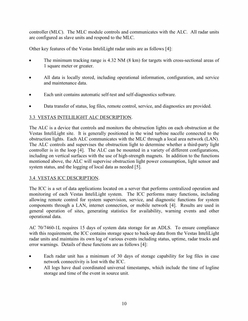
The Vestas InteliLight system warning zone is the designated area around the obstruction(s), which triggers the obstruction warning lights activation when entered by an incoming aircraft. The radar tracking perimeter around the warning zone is set to be a minimum of 3 NM from the obstruction. To ensure the obstruction lights are activated promptly, the Vestas InteliLight system establishes tracks well beyond the 3-NM perimeter. As shown in figure 4, multiple radar units with overlapping coverage areas can be used to ensure adequate coverage of the warning zone.
Figure 4. Vestas InteliLight Warning Zone Perimeter for a Wind Farm Application [4]
3.6 VESTAS INTELILIGHT SYSTEM FAIL-SAFE DESIGN.
Each Vestas InteliLight system component contains built-in fail-safe mechanisms ensuring end-to-end (i.e., aircraft detection-to-obstruction light illumination) aviation safety control. The Vestas InteliLight system radar units and ALCs are designed to share information through the network related to error warnings. Any errors detected by components within the network are immediately reported to the ICC. The ICC also polls each radar unit 3 to 5 times daily to discover undetected communication problems or complete system failures.

12
Various failure scenarios examples and the Vestas InteliLight system responses are as follows [4]: • Radar unit failure:
The Vestas InteliLight radar unit includes failure detection mechanisms for external environmental effects and internal errors. The failure is detected automatically and reported to the ICC. The MLC will cease to generate obstruction light off signals to the ALCs, and all obstruction lights will be activated.
• ALC failure: The ALCs are monitored by the MLC, which detects and report ALC errors to the ICC. The obstruction lights at the ALC location will be activated, while the remaining lights continue to operate as normal.
• Obstruction light failure: Obstruction light failures are detected by the ALC and reported to the ICC. The remaining lights will continue to operate normally.
• Wind farm network failure:
If any radar unit connectivity is not detected, all obstruction lighting will be activated. If ALC connectivity is not detected, the obstruction lights at that location will be activated. Vestas states that, “the wind park LAN network is also used for operation of the entire wind park and hence has high reliability” [4].
• ICC communications failure: If the ICC is unable to be contacted, each Vestas InteliLight site will continue its normal operations independently from the ICC and log its operational data locally. As soon as the ICC comes online and is able to be contacted, all of the logged data recorded during this period is uploaded to ICC for analysis.
• Radar malfunction due to icing:
The Vestas InteliLight system maintains the radar unit at ambient temperature to limit accumulation of icing. If ice or snow is present, the radar’s self-test function will detect any degradation in the radar’s signal before this becomes a safety concern. If the radar unit enters an inoperable state, the radar will enter an error state, activating the obstruction lights [5].
13
4. VESTAS INTELILIGHT SYSTEM INSTALLATION DESCRIPTIONS.
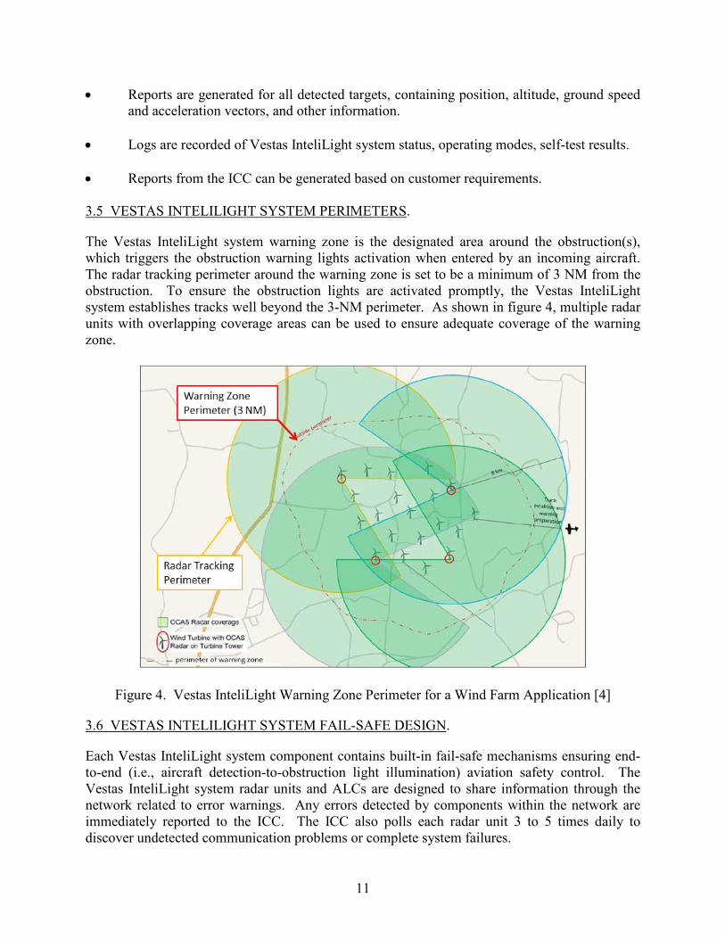
Performance assessments of the Vestas InteliLight system were conducted at two installation sites: (1) the Braderup Wind Park, located near Braderup Germany, and (2) the Hancock Wind Project, located in Hancock County, Maine. Sections 4.1 and 4.2 provide details of these installations. 4.1 DESCRIPTION OF THE BRADERUP WIND PARK INSTALLATION.
The first Vestas InteliLight system assessed by ATR personnel was installed on a wind turbine at the Braderup Wind Park, a wind turbine farm located near the town of Braderup, in northern Germany. As shown in figure 5, this site was located a short distance south of the border between Denmark and Germany. The Braderup Wind Park contains six Vestas V112-3.3MW™ wind turbines, which are shown in figure 6. These turbines reach up to 574 ft (175 m) AGL at their highest point.
Figure 5. Braderup Wind Park Location

14
Figure 6. Wind Turbines at the Braderup Wind Park
Four additional wind turbine farms were located in the vicinity of the Braderup Wind Park, as shown in figure 7. Including the six wind turbines contained in the Braderup Wind Park, there was a total of 47 wind turbines located inside the 3-NM warning zone perimeter around the Vestas InteliLight radar installed for this assessment. Also inside this warning zone was Sportfluggruppe (SFG) Leck Air Base in the town of Leck. The existence of the wind turbines and the SFG Leck Air Base presented an opportunity for ATR personnel to assess the Vestas InteliLight system performance in an environment with a significant amount of radar clutter.
Figure 7. Map Showing Ground Clutter Around the Braderup Wind Park

15
Figure 8 shows an overview of the Vestas InteliLight system installation on a wind turbine at the Braderup Wind Park. This installation consisted of the following components [6]: • A radar unit mounted on the side of the wind turbine tower • An ALC unit mounted inside the turbine • A temporary monitoring location at ground level beneath the turbine • Two obstruction lights on top of the nacelle The radar was mounted at a height of 115 ft (35 m) AGL, as shown in figure 9.
Figure 8. Vestas InteliLight System Installation at the Braderup Wind Park

16
Figure 9. Vestas InteliLight Radar Position
Beneath the turbine, a pop-up tent was set up by Vestas for ATR personnel to monitor the Vestas InteliLight system’s performance. This pop-up tent included a computer monitor showing live radar tracks and system status, as shown in figure 10. It should be noted, this computer monitor (graphical user interface) was only available for the assessment.
Figure 10. Radar Interface Monitored During Assessment

17
The Vestas InteliLight system was connected to a low-intensity, red obstruction light and a high-intensity, flashing obstruction light installed on the wind turbine nacelle. Both types of obstruction lights were visible from the aircraft during the assessment. To allow FAA ATR personnel on the ground to monitor these lights, Vestas personnel installed a webcam to transmit video on a computer monitor at ground level, as shown in figure 11. It should be noted, the video feed was only available for the assessment. An additional steady burning obstruction light controlled by the Vestas InteliLight system was also installed at ground level by Vestas to provide ATR personnel additional evidence the system was functioning as required.
Figure 11. Camera Feed Used to Monitor Obstruction Light Status During Braderup Assessment
4.2 DESCRIPTION OF THE HANCOCK WIND PROJECT INSTALLATION.
The second performance assessment conducted by ATR personnel was conducted on a Vestas InteliLight system installed at the Hancock Wind Project in Hancock County, Maine. As shown in figure 12, this site was located approximately 27 NM east of Bangor, Maine, and 10 NM north of the town of Franklin, Maine. The Hancock Wind Project contains 17 Vestas V117-3.0MW™ wind turbines. These turbines reach up to 574 ft (175 m) AGL and 1087 ft (331 m) mean sea level (MSL) at their highest point.

18
Figure 12. Hancock Wind Project Location
As shown in figure 13, 18 additional wind turbines are located just south of the Hancock Wind Project site inside the ADLS warning zone perimeter. These are part of the adjacent Bull Hill Wind Project. Figure 14 shows turbines from both wind farms in relation to one another. While the Bull Hill turbines are not currently connected to the Vestas InteliLight system installed at the Hancock Wind Project, they do provide a source of potential clutter for the Hancock system’s radars.
Figure 13. Map Showing Bull Hill Wind Turbines in Relation to Hancock Wind Project

19
Figure 14. Hancock and Bull Hill Turbines The Vestas InteliLight system assessed at the Hancock Wind Project site consisted of the same X-band radar sensor and other system hardware assessed at the Braderup Site. Figure 15 shows this radar installed at the Hancock site. Unlike the setup at the Braderup Wind Park, there were now three radars installed (rather than a single unit), providing 360° coverage of the site. All radars were installed at a height of 115 ft AGL on turbines at the following locations and azimuths (shown in figure 16) [7]: • Radar Unit 1: Turbine T1, radar bearing 118º azimuth center (ref true North) • Radar Unit 2: Turbine T5, radar bearing 229º azimuth center (ref true North) • Radar Unit 3: Turbine T17, radar bearing 13º azimuth center (ref true North) The Vestas InteliLight system assessed at the Hancock Wind Project also featured the ability to fuse tracks from multiple radar sensors, which provided continuous tracking of aircraft as they pass through the warning zone.

20
Figure 15. Example of Radar Installed at Hancock Wind Project [7]
Figure 16. Map Showing Radar Locations at Hancock Wind Project The monitoring setup provided for FAA ATR personnel to observe the system performance was similar to that used at the Braderup Wind Park site. Beneath the southernmost radar site, a pop-up tent was set up by Vestas for ATR personnel to monitor the Vestas InteliLight system’s performance. This pop-up tent included a computer monitor showing live radar tracks and
21
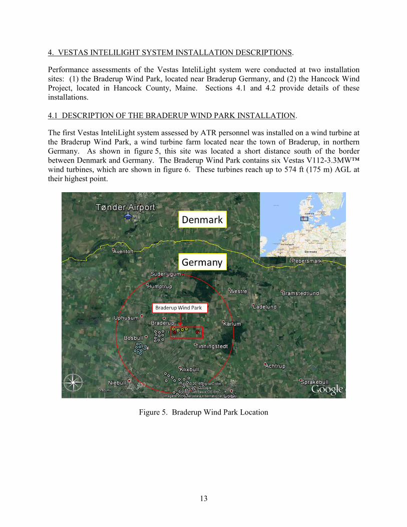
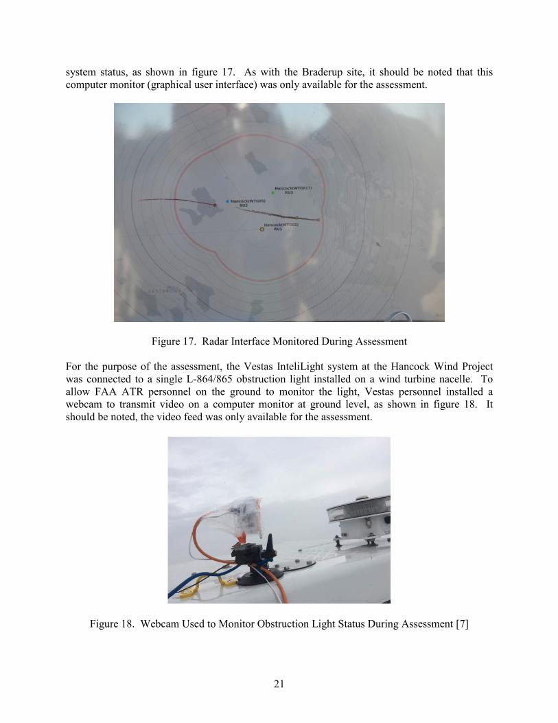
system status, as shown in figure 17. As with the Braderup site, it should be noted that this computer monitor (graphical user interface) was only available for the assessment.
Figure 17. Radar Interface Monitored During Assessment For the purpose of the assessment, the Vestas InteliLight system at the Hancock Wind Project was connected to a single L-864/865 obstruction light installed on a wind turbine nacelle. To allow FAA ATR personnel on the ground to monitor the light, Vestas personnel installed a webcam to transmit video on a computer monitor at ground level, as shown in figure 18. It should be noted, the video feed was only available for the assessment.
Figure 18. Webcam Used to Monitor Obstruction Light Status During Assessment [7]

22
5. THE FAA ASSESSMENTS OF THE VESTAS INTELILIGHT SYSTEM.
Sections 5.1 and 5.2 describe the assessments conducted at the Braderup Wind Park and Hancock Wind Project sites. 5.1 THE FAA ASSESSMENT OF THE VESTAS INTELILIGHT SYSTEM AT THE BRADERUP WIND PARK.
5.1.1 The FAA Flight Assessment.
To properly assess the Vestas InteliLight system performance, ATR personnel conducted a series of flight patterns to assess the system’s response to aircraft operating around the warning zone at various altitudes, flight paths, speed, etc. A majority of these patterns were based on similar flight patterns conducted during previous FAA ADLS assessments. Each pattern was designed to assess a specific ADLS parameter to determine if the system meets the requirements in AC 70/7460-1L. A total of 12 flight maneuvers were made in a Cessna 172, following these patterns over the course of two flights. These maneuvers are described below: 1. The aircraft flew through the center of the warning zone at 800 ft AGL, three times at
various headings. 2. The aircraft flew adjacent to the wind turbine farm perimeter at 800 ft AGL, two times
at various headings. 3. The aircraft flew directly through the warning zone at altitudes of 1500 and 2000 ft
AGL. 4. The aircraft completed several tight circles over the wind turbine farm and radar cone of
silence. It then exited the wind turbine farm at a different heading from the entry heading. This was completed two times at various headings and altitudes.
5. The aircraft flew along the perimeter of the warning zone at 800 ft AGL at a low radial speed.
6. The aircraft flew to the wind farm at 3000 ft, and then steeply descended to an altitude
of 1500 ft inside the warning zone. 7. The aircraft flew to the warning zone from a location where the radar shadow masked
the aircraft from initially being detected by the Vestas InteliLight system. The intent of this pattern was to identify how quickly the Vestas InteliLight system could detect the aircraft without the benefit of early detection.
ATR personnel used the Cessna 172 aircraft shown in figure 19 to conduct the flight pattern tests. These flights were operated out of the Tønder Airport, located outside the city of Tønder, Denmark. Figure 20 shows a Google Earth™ map image overlaid with the flight tracks (shown in light blue) recorded by a global positioning system (GPS) unit on board the aircraft over the course of the two flights.

23
Figure 19. Cessna 172 Used for Braderup Assessment
Figure 20. The GPS Flight Track Data From the Aircraft: Braderup Assessment
5.1.2 The FAA Component Failure Assessment.
In addition to the flight tests, ATR personnel also performed an assessment of the Vestas InteliLight system’s fail-safe mechanisms designed to monitor and respond to certain component failures. This portion of the assessment was performed on the ground at the test site where the

24
Vestas InteliLight system and associated obstruction lighting could be observed. The specific parameters that were assessed, as addressed in AC 70/7460-1L, included the following.
• The response of the Vestas InteliLight system in the event there is a component or system
failure: the Vestas InteliLight system should automatically turn on all the obstruction lighting and operate in accordance with AC 70/7460-1L as if the lighting operated separately from the system and must remain in this state until the Vestas InteliLight system and its components are restored.
• The response of the Vestas InteliLight system in the event that an individual obstruction
light cannot be controlled by the Vestas InteliLight system, but the rest of the Vestas InteliLight system is functional: that particular obstruction light should automatically turn on and operate in accordance with AC 70/7460-1L as if it was not controlled by the Vestas InteliLight system. The remaining obstruction lights can continue to be controlled by the Vestas InteliLight system. The obstruction lighting must remain in this state until the Vestas InteliLight system and its components are restored.
• Verification that the Vestas InteliLight system’s communication and operational status
was checked at least once every 24 hours to ensure both are operational. • Verification that the Vestas InteliLight system was able to detect an aircraft with a cross-
sectional area of 1 square meter or more within the detection area. • Verification that the Vestas InteliLight system maintains a log of activity data for a
period of no less than the previous 15 days. This data shall include, but not be limited to, the date, time, duration of all system activations/deactivations, track of aircraft activity, maintenance issues, system errors, communication and operational issues, lighting outages/issues, etc.
• Verification that the Vestas InteliLight system components do not use the devices
identified in Title 47 CFR Part 15, “Radio Frequency Devices” [8]. • If equipped with a voice/audio option, verify that the Vestas InteliLight system operated
within the performance specifications for the voice/audio option provided in Chapter 14 of AC 70/7460-1L (See appendix A).
5.2 THE FAA ASSESSMENT OF THE VESTAS INTELILIGHT SYSTEM AT THE HANCOCK WIND PROJECT.
5.2.1 The FAA Flight Assessment.
ATR personnel conducted a condensed flight assessment of the Vestas InteliLight system at the Hancock Wind Project site similar to that conducted at the Braderup Wind Park. A total of 7 flight maneuvers were flown. These maneuvers are described below. Note: due to the uneven terrain of varying heights in and around the Hancock Wind Project site, altitudes of the

25
maneuvers will be described in MSL rather than AGL. The maximum height of the wind turbine blades is 1087 feet MSL: 1. The aircraft flew through the center of the wind farm, three times at various headings
and altitudes. 2. The aircraft completed several tight circles over the wind turbine farm at 1700 ft MSL.
It then exited the wind turbine farm at a different heading from the entry heading.
3. The aircraft flew to the wind farm at 3400 ft MSL, and then steeply descended to an altitude of 1700 ft MSL over the wind farm.
4. The aircraft flew along the perimeter of the warning zone at 1200 ft MSL at a low radial
speed.
5. The aircraft descended from 1500 to 700 ft MSL while completing tights turns over the wind turbine farm.
ATR personnel used a Cessna 172 aircraft to conduct the flight maneuvers. These flights were operated out of the Bangor International Airport, located outside the city of Bangor, Maine. Figure 21 shows a Google Earth™ map image overlaid with the flight tracks (shown in light blue) recorded by the FAA’s global positioning system (GPS) unit on board the aircraft over the course of the flight.
Figure 21. The GPS Flight Track Data From the Aircraft: Hancock Assessment

26
5.2.2 The FAA Component Failure Assessment.
In addition to the flight tests, ATR personnel performed a brief assessment of the Vestas InteliLight system’s fail-safe mechanisms designed to monitor and respond to certain component failures. Similar to the assessment at the Braderup Wind Park site, this portion of the assessment was performed on the ground at the test site where the Vestas InteliLight system and associated obstruction lighting could be observed. ATR personnel observed the responses of the Vestas InteliLight system to various simulated component and system failures. The Vestas InteliLight system should automatically turn on all the obstruction lighting and operate in accordance with AC 70/7460-1L as if the lighting operated separately from the system and must remain in this state until the Vestas InteliLight system and its components are restored. 6. THE RESULTS OF THE FAA ASSESSMENTS.
The performance assessments of the Vestas InteliLight system were based on the specifications and criteria provided in AC 70/7460-1L. AC 70/7460-1L lists specifications for basic functions, detection performance, and system output. The following sections document the performance of the Vestas InteliLight system along with the data collected during the performance assessment and discuss how it relates to the AC 70/7460-1L performance specifications. 6.1 RESULTS OF THE ASSESSMENT AT THE BRADERUP WIND PARK.
6.1.1 Basic Function Assessment.
Prior to the flight assessment, the Vestas InteliLight system was turned on and calibrated, and ATR personnel verified that the system was fully operational. ATR personnel also verified that, without any aircraft present in the area, the system continuously scanned the area and the obstruction lighting remained off. Before beginning the scheduled flight patterns, ATR personnel confirmed that the system was standing by and was not tracking any other aircraft in the area. With the system ready and the obstruction lighting off, ATR personnel proceeded to assess the Vestas InteliLight system’s detection performance. During the assessment flights, the Vestas InteliLight system recorded radar tracks for all airborne targets operating within the vicinity of the system while the performance assessment was conducted. These radar tracks were exported as Keyhole Markup Language files viewable in Google Earth. Figure 22 shows a record of the entire FAA assessment flight pattern. The dark blue lines represent the real-time tracks produced from the Vestas InteliLight system, and the light blue lines represent the tracks recorded by the GPS on board the aircraft. The Vestas InteliLight radar track and GPS tracks were slightly offset for better visibility. As shown in figure 22, the radar tracks from the Vestas InteliLight system matched the GPS tracks very closely. The Vestas InteliLight system radar consistently tracked the aircraft at ranges of 5.2 NM or more. This provided adequate coverage to activate the obstruction lights when the aircraft reached a distance of 3 NM (5.5 km) from the obstructions. The only exceptions to this tracking performance were flights inside the shadow behind the radar and flights in the area directly above the radar, known as the radar cone of silence. As Vestas personnel noted, the
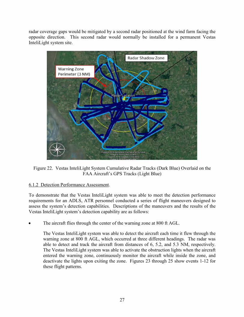
27
radar coverage gaps would be mitigated by a second radar positioned at the wind farm facing the opposite direction. This second radar would normally be installed for a permanent Vestas InteliLight system site.
Figure 22. Vestas InteliLight System Cumulative Radar Tracks (Dark Blue) Overlaid on the FAA Aircraft’s GPS Tracks (Light Blue)
6.1.2 Detection Performance Assessment.
To demonstrate that the Vestas InteliLight system was able to meet the detection performance requirements for an ADLS, ATR personnel conducted a series of flight maneuvers designed to assess the system’s detection capabilities. Descriptions of the maneuvers and the results of the Vestas InteliLight system’s detection capability are as follows: • The aircraft flies through the center of the warning zone at 800 ft AGL.
The Vestas InteliLight system was able to detect the aircraft each time it flew through the warning zone at 800 ft AGL, which occurred at three different headings. The radar was able to detect and track the aircraft from distances of 6, 5.2, and 5.3 NM, respectively. The Vestas InteliLight system was able to activate the obstruction lights when the aircraft entered the warning zone, continuously monitor the aircraft while inside the zone, and deactivate the lights upon exiting the zone. Figures 23 through 25 show events 1-12 for these flight patterns.

28
• The aircraft flies adjacently to the wind turbine farm perimeter at 800 ft AGL.
During both flights adjacent to the wind farm, the Vestas InteliLight system was able to detect and track the aircraft at a distance of 6 NM from the radar and the obstruction lights were activated when the aircraft entered the warning zone. For the first pattern flown, the system maintained continuous monitoring of the aircraft within the warning zone. However, on the second flight the radar lost contact with aircraft as it entered the radar shadow. The aircraft was immediately reacquired upon the aircraft exiting the radar shadow. The obstruction lights were kept on by the system’s lost aircraft timer. Figures 26 through 28 show events 13-22 for these flight patterns.
• The aircraft flies directly through the warning zone at altitudes of 1500 and 2000 ft AGL.
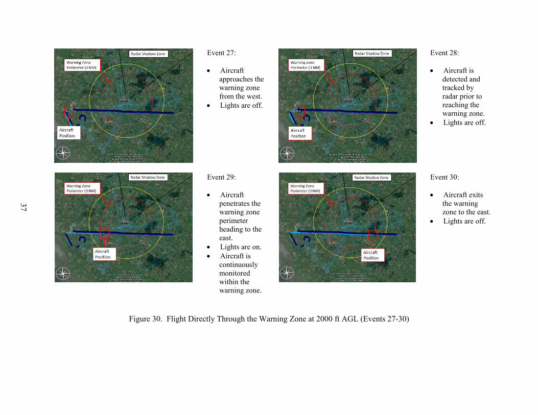
The Vestas InteliLight system was able to detect and track the aircraft at distances of 5.4 and 6 NM from the radar when approaching the warning zone at 1500 and 2000 ft AGL, respectively. The Vestas InteliLight system was able to activate the obstruction lights when the aircraft entered the warning zone, continuously monitor the aircraft while inside the zone, and deactivate the lights upon exiting the zone. Figures 29 and 30 show events 23-30 for these flight patterns.
• The aircraft flies to the wind farm and completes tight circling turns over the wind turbine farm and radar cone of silence. While initially detecting and tracking the aircraft and activating the obstruction lights at the appropriate time upon entering the warning zone, the Vestas InteliLight system lost radar contact with the aircraft during both of these flight patterns when entering the cone of silence above the radar, as expected. The Vestas InteliLight system was able to reacquire the aircraft at distances of 0.7 and 0.8 NM, respectively, upon emerging from the cone of silence. The Vestas InteliLight system’s lost aircraft timer ensured the obstruction lights remained lit when the radar could not track the aircraft. Figures 31 through 34 show events 31-42 for these flight patterns.
• The aircraft flies along the perimeter of the warning zone at 800 ft AGL at a low radial speed. The Vestas InteliLight system was able to detect and track the aircraft at a distance of 5.2 NM. The system was also able to activate the obstruction lights when the aircraft entered the warning zone, continuously monitor the aircraft while inside the zone, and deactivate the lights upon exiting the zone. Figure 35 shows events 43-46 for this flight pattern.
• The aircraft flies to the wind farm at 3000 ft, and then steeply descends to an altitude of 1500 ft inside the warning zone. The Vestas InteliLight system detected and tracked the aircraft from a distance of 6.5 NM, and the system activated the obstruction lights upon the aircraft entering the warning zone and rapidly descending to 1500 ft AGL. The aircraft then flew over the

29
radar and entered the radar shadow. At this point, the Vestas InteliLight system lost contact with the aircraft. The Vestas InteliLight system’s lost aircraft timer ensured the obstruction lights remained lit when the radar could not track the aircraft. Figure 36 shows events 47-50 for this flight pattern.
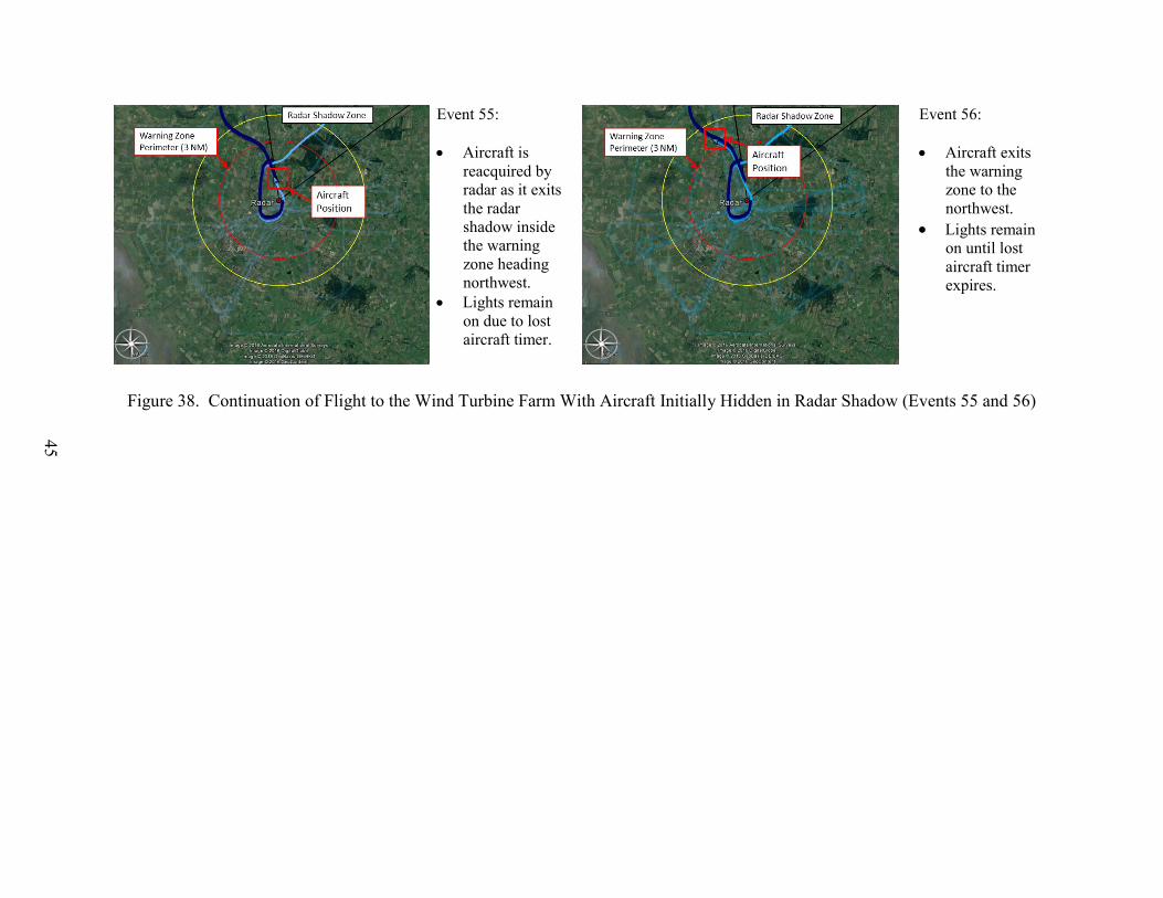
• The aircraft flies to the warning zone from a location where the radar shadow masked the aircraft from initially being detected by the Vestas InteliLight system. As expected, the Vestas InteliLight system did not detect the aircraft as it approached and entered the warning zone from inside the radar shadow. However, the aircraft was detected immediately upon the aircraft exiting the radar shadow while inside the warning zone, and the obstruction lights were activated. The aircraft completed another pass through the radar shadow, with the Vestas InteliLight system again losing and reacquiring the aircraft. The Vestas InteliLight system’s lost aircraft timer ensured the obstruction lights remained lit when the radar could not track the aircraft. Figures 37 and 38 show events 51-56 for this flight pattern.

30
Event 1: • Aircraft
approaches the warning zone from the northwest.
• Lights are off.
Event 2: • Aircraft is
detected and tracked by radar prior to reaching the warning zone.
• Lights are off.
Event 3: • Aircraft
penetrates the warning zone perimeter heading southeast.
• Lights are on.
• Aircraft is continuously monitored within the warning zone.
Event 4: • Aircraft exits the
warning zone to the southeast.
• Lights are off.
Figure 23. Flight Directly to and Over the Wind Turbine Farm at 800 ft AGL From the Northwest (Events 1-4)

31
Event 5: • Aircraft
approaches the warning zone from the west.
• Lights are off.
Event 6: • Aircraft is
detected and is tracked by radar prior to reaching the warning zone.
• Lights are off.
Event 7: • Aircraft
penetrates the warning zone perimeter heading to the east.
• Lights are on.
• Aircraft is continuously monitored within the warning zone.
Event 8: • Aircraft exits
the warning zone to the east.
• Lights are off.
Figure 24. Flight Directly to and Over the Wind Turbine Farm at 800 ft AGL From the West (Events 5-8)

32
Event 9: • Aircraft
approaches the warning zone from the east.
• Lights are off.
Event 10: • Aircraft is
detected and tracked by radar prior to reaching the warning zone.
• Lights are off.
Event 11: • Aircraft
penetrates the warning zone perimeter heading to the west.
• Lights are on. • Aircraft is
continuously monitored within the warning zone.
Event 12: • Aircraft exits
the warning zone to the southwest.
• Lights are off.
Figure 25. Flight Directly to and Over the Wind Turbine Farm at 800 ft AGL From the East (Events 9-12)

33
Event 13: • Aircraft
approaches the warning zone from the southeast.
• Lights are off.
Event 14: • Aircraft is
detected and is tracked by radar prior to reaching the warning zone.
• Lights are off.
Event 15: • Aircraft
penetrates the warning zone perimeter heading northwest.
• Lights are on. • Aircraft is
continuously monitored within the warning zone.
Event 16: • Aircraft exits
the warning zone to the northwest.
• Lights are off.
Figure 26. Flight Adjacent to Wind Turbine Farm at 800 ft AGL From the Southeast (Events 13-16)

34
Event 17: • Aircraft
approaches the warning zone from the east.
• Lights are off.
Event 18: • Aircraft is
detected and tracked by radar prior to reaching the warning zone.
• Lights are off.
Event 19: • Aircraft
penetrates the warning zone perimeter heading to the west.
• Lights are on.
Event 20: • Aircraft turns
toward the east and flies along the edge of the wind farm.
• Radar track is lost due to radar shadow.
• Lights remain on due to lost aircraft timer.
Figure 27. Flight Adjacent to Wind Turbine Farm at 800 ft AGL From the East (Events 17-20)

35
Event 21: • Aircraft
continues to fly east and is reacquired by the radar upon leaving the radar shadow.
• Aircraft is monitored within the warning zone.
• Lights remain on due to lost aircraft timer.
Event 22: • Aircraft exits
the warning zone to the east.
• Lights remain on until lost aircraft timer expires.
Figure 28. Continuation of Flight Adjacent to Wind Turbine Farm at 800 ft AGL From the East (Events 21 and 22)

36
Event 23: • Aircraft
approaches the warning zone from the northeast.
• Lights are off.
Event 24: • Aircraft is
detected and tracked by radar prior to reaching the warning zone.
• Lights are off.
Event 25: • Aircraft
penetrates the warning zone perimeter heading to the southwest.
• Lights are on. • Aircraft is
continuously monitored within the warning zone.
Event 26: • Aircraft exits
the warning zone to the southwest
• Lights are off.
Figure 29. Flight Directly Through the Warning Zone at 1500 ft AGL (Events 23-26)
37
Event 27: • Aircraft
approaches the warning zone from the west.
• Lights are off.
Event 28: • Aircraft is
detected and tracked by radar prior to reaching the warning zone.
• Lights are off.
Event 29: • Aircraft
penetrates the warning zone perimeter heading to the east.
• Lights are on. • Aircraft is
continuously monitored within the warning zone.
Event 30: • Aircraft exits
the warning zone to the east.
• Lights are off.
Figure 30. Flight Directly Through the Warning Zone at 2000 ft AGL (Events 27-30)

38
Event 31: • Aircraft
approaches the warning zone from the southwest.
• Lights are off.
Event 32: • Aircraft is
detected and tracked by radar prior to reaching the warning zone.
• Lights are off.
Event 33: • Aircraft
penetrates the warning zone perimeter heading to the northeast.
• Lights are on.
Event 34: • Aircraft
completes two steep turns over the radar site.
• Radar track lost.
• Lights remain on due to lost aircraft timer.
Figure 31. Circling Flight Over the Wind Turbine Farm at 800 ft AGL, Exiting to the Northwest (Events 31-34)

39
Event 35: • Aircraft flies
northwest and is reacquired by the radar upon leaving the cone of silence.
• Aircraft is monitored within the warning zone.
• Lights remain on due to lost aircraft timer.
Event 36: • Aircraft exits
the warning zone to the northwest.
• Lights remain on until lost aircraft timer expires.
Figure 32. Continuation of Circling Flight Over the Wind Turbine Farm at 800 ft AGL, Exiting to the Northwest (Events 35 and 36)

40
Event 37: • Aircraft
approaches the warning zone from the southeast.
• Lights are off.
Event 38: • Aircraft is
detected and tracked by radar prior to reaching the warning zone.
• Lights are off.
Event 39: • Aircraft
penetrates the warning zone perimeter heading to the north.
• Lights are on.
Event 40: • Aircraft
completes two steep turns over the radar site while descending from 3000 to 1500 ft AGL.
• Radar track lost.
• Lights remain on due to lost aircraft timer.
Figure 33. Circling Flight Over the Wind Turbine Farm Descending From 3000 to 1500 ft AGL (Events 37-40)

41
Event 41: • Aircraft flies
southwest and is reacquired by the radar upon leaving the cone of silence.
• Aircraft is monitored within the warning zone.
• Lights remain on due to lost aircraft timer.
Event 42: • Aircraft exits
the warning zone to the southwest.
• Lights remain on until lost aircraft timer expires.
Figure 34. Circling Flight Over the Wind Turbine Farm Descending From 3000 to 1500 ft AGL (Events 41 and 42)

42
Event 43: • Aircraft
approaches the warning zone from the northwest.
• Lights are off.
Event 44: • Aircraft is
detected and tracked by radar prior to reaching the warning zone.
• Lights are off.
Event 45: • Aircraft
penetrates the warning zone perimeter heading to the southeast.
• Lights are on. • Aircraft is
continuously monitored within the warning zone.
Event 46: • Aircraft exits
the warning zone to the southeast.
• Lights are off.
Figure 35. Flight Along the Warning Zone Perimeter at 800 ft AGL (Events 43-46)

43
Event 47: • Aircraft
approaches the warning zone from the southwest.
• Lights are off.
Event 48: • Aircraft is
detected and tracked by radar prior to reaching the warning zone.
• Lights are off.
Event 49: • Aircraft
penetrates the warning zone perimeter heading to the northeast.
• Aircraft is tracked as it steeply descends to 1500 ft AGL
• Radar track is lost over the radar.
• Lights remain on due to lost aircraft timer.
Event 50: • Aircraft exits
the warning zone to the northeast
• Lights remain on until lost aircraft timer expires.
Figure 36. Descending Flight Into the Warning Zone (Events 47-50)

44
Event 51: • Aircraft
approaches the warning zone from the northeast inside the radar shadow.
• Lights are off.
Event 52: • Aircraft
penetrates the warning zone perimeter heading to the southwest.
• Lights are off. • Aircraft is not
detected within the warning zone due to radar shadow.
Event 53: • Aircraft is
reacquired by radar as it exits the radar shadow inside the warning zone.
• Lights are on.
Event 54: • Aircraft
completes a turn over the radar, entering the radar shadow.
• Radar track is lost.
• Lights remain on due to lost aircraft timer.
Figure 37. Flight to the Wind Turbine Farm With Aircraft Initially Hidden in Radar Shadow (Events 51-54)
45
Event 55: • Aircraft is
reacquired by radar as it exits the radar shadow inside the warning zone heading northwest.
• Lights remain on due to lost aircraft timer.
Event 56: • Aircraft exits
the warning zone to the northwest.
• Lights remain on until lost aircraft timer expires.
Figure 38. Continuation of Flight to the Wind Turbine Farm With Aircraft Initially Hidden in Radar Shadow (Events 55 and 56)

46
6.1.3 Component Failure Assessment.
To demonstrate that the Vestas InteliLight system was able to meet the component failure requirements for an ADLS, ATR personnel conducted a series of activities designed to test the system’s component failure responses. Descriptions of the activities and the results of the Vestas InteliLight system’s failure response are as follows: • Individual Component and Obstruction Light Control Failure
ATR personnel witnessed multiple simulated network and radar unit failures and verified successful response and recovery of the Vestas InteliLight system. Vestas personnel simulated the failures by unplugging network and/or power cables to these components. The obstruction lights were activated on within 1-2 seconds of each component going offline. Once the components were restored to full functionality, the system returned to a normal standby function.
• Communication and Status Monitoring ATR personnel verified that the Vestas InteliLight system communication and operational status were able to be checked at least once every 24 hours to ensure both were operational.
• Target Size ATR personnel confirmed that the Vestas InteliLight system could detect an object with a radar cross-sectional area of 1 square meter or more within the detection area. This was accomplished by flying an aircraft straight toward the Vestas InteliLight system radar unit, which resulted in the system being able to detect the narrow profile of the aircraft.
• Activity Log Vestas indicated that the data could be stored for 30 days or more, depending on the user’s requirement, which satisfies the 15-day requirement of AC 70/7460-1L [1].
• FCC Part 15 Compliance Based on the documentation provided to the ATR personnel by the Vestas personnel, it was verified that the Vestas InteliLight system components do not use FCC Part 15 devices [8].
• Audio/Voice Option The demonstrated Vestas InteliLight system was not configured with the optional voice/audio feature; therefore, this was not assessed. As stated in AC 70/7460-1L, this is not a required ADLS component [1].

47
6.2 RESULTS OF THE ASSESSMENT AT THE HANCOCK WIND PROJECT.
6.2.1 Basic Function Assessment.
Similar to the Braderup assessment, the Vestas InteliLight system was turned on and calibrated, and ATR personnel verified that the system was operational prior to the flight assessment. ATR personnel also verified that, without any aircraft present in the area, the system continuously scanned the area and the obstruction lighting remained off. Before beginning the scheduled flight patterns, ATR personnel confirmed that the system was standing by and was not tracking any other aircraft in the area. With the system ready and the obstruction lighting off, ATR personnel proceeded to assess the Vestas InteliLight system’s detection performance. Figure 39 shows a record of the entire FAA assessment flight pattern and radar tracks from the Vestas InteliLight system. The yellow lines represent the real-time tracks produced from the Vestas InteliLight system, and the light blue lines represent the tracks recorded by the GPS on board the aircraft. As with the Braderup assessment, the radar tracks from the Vestas InteliLight system matched the GPS tracks very closely. The system provided adequate coverage to activate the obstruction light when the aircraft reached a distance of 3 NM (5.5 km) from the obstructions. The only interruption in radar tracking occurred during a brief period of time when the aircraft was directly over one of the radar units and occurred at an altitude above the required coverage volume.
Figure 39. Vestas InteliLight System Cumulative Radar Tracks (Yellow) Overlaid on the FAA
Aircraft’s GPS Tracks (Light Blue)

48
6.2.2 Detection Performance Assessment.
To demonstrate that the Vestas InteliLight system was able to meet the detection performance requirements for an ADLS, ATR personnel conducted a series of flight maneuvers designed to assess the system’s detection capabilities. Note: Due to the uneven terrain of varying heights in and around the Hancock Wind Project site, altitudes of the maneuvers will be described in MSL rather than AGL. (The maximum height of the wind turbine blades is 1087 feet MSL.) Descriptions of the maneuvers and the results of the Vestas InteliLight system’s detection capability are as follows: • The aircraft flies through the center of the warning zone.
The Vestas InteliLight system was able to detect the aircraft each time it flew through the warning zone at altitudes of 2300, 1500, and 1200 ft MSL, which each occurred at three different headings. The radar was able to detect and track the aircraft from distances of 5, 6, and 4.8 NM, respectively. The Vestas InteliLight system was able to activate the obstruction light when the aircraft entered the warning zone, continuously monitor the aircraft while inside the zone, and deactivate the light upon exiting the zone. The only interruption in radar tracking occurred during a brief period of time when the aircraft was directly over one of the radar units and occurred at 2400 ft MSL, which was above the required coverage volume height (2087 ft MSL). Figures 40 through 43 show events 1-14 for these flight patterns.
• The aircraft flies to the wind farm and completes tight circling turns over the wind turbine farm at 1700 ft MSL. The Vestas InteliLight system was able to detect and track the aircraft at a distance of 5.4 NM. The Vestas InteliLight system was able to activate the obstruction light when the aircraft entered the warning zone, continuously monitor the aircraft while completing several tight turns at two locations inside the zone, and deactivate the light upon exiting the zone. Figures 44 and 45 show events 15-20 for these flight patterns.
• The aircraft flies to the wind farm at 3400 ft MSL, and then steeply descends to an altitude of 1700 ft MSL inside the warning zone. The Vestas InteliLight system was able to activate the obstruction light when the aircraft entered the warning zone, monitor the aircraft while inside the zone as the aircraft descended rapidly from 3400 to 1700 ft MSL, and deactivate the light upon exiting the zone. A brief interruption in radar monitoring of approximately 5 seconds occurred during this maneuver; however, the light remained on due to the lost aircraft timer. Figure 46 shows events 21-24 for this flight pattern.
• The aircraft flies along the perimeter of the warning zone at 1200 ft MSL at a low radial speed. The Vestas InteliLight system was able to detect and track the aircraft as it flew along the edge of the warning zone perimeter. The system activated the obstruction light when the

49
aircraft entered the warning zone, continuously monitored the aircraft while inside the zone, and deactivated the light upon exiting the zone. Figure 47 shows events 25-28 for this flight pattern.
• The aircraft completes tight turns over the wind turbine farm while descending rapidly from 1500 ft MSL to 700 ft MSL. The Vestas InteliLight system was able to activate the obstruction light when the aircraft entered the warning zone, continuously monitor the aircraft position as it descended rapidly from 1500 to 700 ft MSL and completed two tight turns, and deactivate the light upon exiting the zone. Figure 48 shows events 29-32 for this flight pattern.

50
Event 1: • Aircraft
approaches the warning zone from the west.
• Light is off.
Event 2: • Aircraft is
detected and tracked by radar prior to reaching the warning zone.
• Light is off.
Event 3: • Aircraft
penetrates the warning zone perimeter heading east.
• Light is on. • Aircraft is
monitored within the warning zone.
Event 4: • Radar track is
lost passing over the radar cone of silence.
• Light remains on due to lost aircraft timer.
Figure 40. Flight Directly to and Over the Wind Turbine Farm at 2300 ft MSL From the West (Events 1-4)

51
Event 5: • Aircraft
continues to fly east and is reacquired by the radar upon leaving the radar cone of silence.
• Aircraft is monitored within the warning zone.
• Light remains on.
Event 6: • Aircraft exits
the warning zone to the east.
• Light is off.
Figure 41. Continuation of Flight Directly to and Over the Wind Turbine Farm at 2300 ft MSL From the West (Events 5 and 6)

52
Event 7: • Aircraft
approaches the warning zone from the northeast.
• Light is off.
Event 8: • Aircraft is
detected and tracked by radar prior to reaching the warning zone.
• Light is off.
Event 9: • Aircraft
penetrates the warning zone perimeter heading to the southwest.
• Light is on. • Aircraft is
continuously monitored within the warning zone.
Event 10: • Aircraft exits
the warning zone to the southwest.
• Light is off.
Figure 42. Flight Directly to and Over the Wind Turbine Farm at 1500 ft MSL From the Northeast (Events 7-10)

53
Event 11: • Aircraft
approaches the warning zone from the south.
• Light is off.
Event 12: • Aircraft is
detected and tracked by radar prior to reaching the warning zone.
• Light is off.
Event 13: • Aircraft
penetrates the warning zone perimeter heading to the north.
• Light is on. • Aircraft is
continuously monitored within the warning zone.
Event 14: • Aircraft exits
the warning zone to the north.
• Light is off.
Figure 43. Flight Directly to and Over the Wind Turbine Farm at 1200 ft MSL From the South (Events 11-14)

54
Event 15: • Aircraft
approaches the warning zone from the north.
• Light is off.
Event 16: • Aircraft is
detected and tracked by radar prior to reaching the warning zone.
• Light is off.
Event 17: • Aircraft
penetrates the warning zone perimeter heading to the south.
• Light is on.
Event 18: • Aircraft
completes two tight turns over the wind turbine farm.
• Light remains on.
Figure 44. Circling Flight Over the Wind Turbine Farm at 1700 ft MSL, Exiting to the West (Events 15-18)
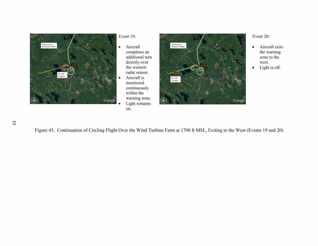
55
Event 19: • Aircraft
completes an additional turn directly over the western radar sensor.
• Aircraft is monitored continuously within the warning zone.
• Light remains on.
Event 20: • Aircraft exits
the warning zone to the west.
• Light is off.
Figure 45. Continuation of Circling Flight Over the Wind Turbine Farm at 1700 ft MSL, Exiting to the West (Events 19 and 20)

56
Event 21: • Aircraft
approaches the warning zone from the west.
• Light is off.
Event 22: • Aircraft is
detected and tracked by radar prior to reaching the warning zone.
• Light is off.
Event 23: • Aircraft
penetrates the warning zone perimeter heading to the southeast.
• Aircraft is monitored within the warning zone, with a brief interruption occurring over radar.
• Light is on.
Event 24: • Aircraft exits
the warning zone to the southeast
• Light is off.
Figure 46. Descending Flight Into the Warning Zone (Events 21-24)

57
Event 25: • Aircraft
approaches the warning zone from the southeast.
• Light is off.
Event 26: • Aircraft is
detected and tracked by radar as it flies along the warning zone perimeter.
• Light is off.
Event 27: • Aircraft
penetrates the warning zone perimeter heading to the northwest.
• Light is on. • Aircraft is
continuously monitored within the warning zone.
Event 28: • Aircraft exits
the warning zone to the northwest.
• Light is off.
Figure 47. Flight Along the Warning Zone Perimeter at 1200 ft MSL (Events 25-28)
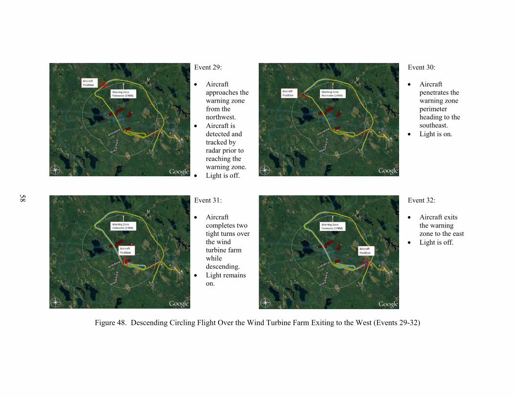
58
Event 29: • Aircraft
approaches the warning zone from the northwest.
• Aircraft is detected and tracked by radar prior to reaching the warning zone.
• Light is off.
Event 30: • Aircraft
penetrates the warning zone perimeter heading to the southeast.
• Light is on.
Event 31: • Aircraft
completes two tight turns over the wind turbine farm while descending.
• Light remains on.
Event 32: • Aircraft exits
the warning zone to the east
• Light is off.
Figure 48. Descending Circling Flight Over the Wind Turbine Farm Exiting to the West (Events 29-32)
59
6.2.3 Component Failure Assessment.
To validate the finding from the previous assessment that the Vestas InteliLight system was able to meet the component failure requirements for an ADLS, ATR personnel conducted an additional component failure assessment. ATR personnel again witnessed multiple simulated network and radar unit failures and verified successful response and recovery of the Vestas InteliLight system. Vestas personnel simulated the failures by unplugging network and/or power cables to these components, as was done during the Braderup assessment. The obstruction light was activated on within 1-2 seconds of each component going offline. Once the components were restored to full functionality, the system returned to a normal standby function. 7. CONCLUSIONS.
The Federal Aviation Administration (FAA) Airport Technology Research and Development Branch conducted performance assessments of the Vestas InteliLight™ X-band system (Vestas InteliLight system) at the Braderup Wind Park, located near Braderup, Germany and at the Hancock Wind Project in Hancock County, Maine. These performance assessments, which included demonstrations, flight testing, and data analysis, were conducted on September 20, 2016 and October 11, 2017, respectively. In these performance assessments, a series of flight patterns were flown against the Vestas InteliLight system to demonstrate that the system could meet the FAA’s performance requirements for aircraft detection lighting systems. In both assessments, the Vestas InteliLight X-band system performed according to the manufacturer’s specifications and met the performance requirements specified in FAA Advisory Circular (AC) 70/7460-1L, “Obstruction Marking and Lighting.” 8. REFERENCES.
1. Federal Aviation Administration, “Obstruction Marking and Lighting,” Advisory Circular (AC) 70/7460-1L–Change 1, October 8, 2016.
2. Patterson, James, Jr., “Performance Assessment of the Laufer Wind Aircraft Detection
System as an Aircraft Detection Lighting System,” FAA technical note DOT/FAA/TC-TN15/54, May 2016.
3. U.S. Department of Commerce, National Telocommunications and Information
Administration, “500 MHz Initiative,” available at https://www.ntia.doc.gov/category/500-mhz-initiative (date last visited 05/11/17).
4. Vestas, “OCAS® X System Description—Revision 4,” Internal report, September 16,
2016. 5. Vestas, “General Specification OCAS X Obstacle Collision Avoidance System,” Internal
report, October 13, 2016.

60
6. Vestas, “OCAS Mk X Test Report—Revision 1,” Internal report, September 23, 2016. 7. Vestas, “Hancock Flight Verification Flight Report—Revision 1,” Internal report,
October 11, 2017. 8. U.S. Federal Register, Title 47 Code of Federal Regulations, Part 15, “Radio Frequency
Devices,” Government Printing Office, Washington, DC.

A-1
APPENDIX A—ADVISORY CIRCULAR 70/7460-1L, CHAPTER 14 AIRCRAFT DETECTION LIGHTING SYSTEMS1
CHAPTER 14. AIRCRAFT DETECTION LIGHTING SYSTEMS
14.1 Purpose. Aircraft Detection Lighting Systems (ADLS) are sensor-based systems designed to detect aircraft as they approach an obstruction or group of obstructions; these systems automatically activate the appropriate obstruction lights until they are no longer needed by the aircraft. This technology reduces the impact of nighttime lighting on nearby communities and migratory birds and extends the life expectancy of obstruction lights. 14.2 General Standards. 14.2.1 The system should be designed with sufficient sensors to provide complete detection coverage for aircraft that enter a three-dimensional volume of airspace, or coverage area, around the obstruction(s) (see Figure A-27 in Appendix A), as follows: 1. Horizontal detection coverage should provide for obstruction lighting to be activated and illuminated prior to aircraft penetrating the perimeter of the volume, which is a minimum of 3 NM (5.5 km) away from the obstruction or the perimeter of a group of obstructions. 2. Vertical detection coverage should provide for obstruction lighting to be activated and illuminated prior to aircraft penetrating the volume, which extends from the ground up to 1000 feet (304 m) above the highest part of the obstruction or group of obstructions, for all areas within the 3-NM (5.5-km) perimeter defined in subparagraph 14.2.1 1 above. 3. In some circumstances, it may not be possible to meet the volume area defined above because the terrain may mask the detection signal from acquiring an aircraft target within the 3-NM (5.5-km) perimeter. In these cases, the sponsor should identify these areas in their application to the FAA for further evaluation. 4. In some situations, lighting not controlled by the ADLS may be required when the 3-NM (5.5-km) perimeter is not achievable to ensure pilots have sufficient warning before approaching the obstructions. 14.2.2 The ADLS should activate the obstruction lighting system in sufficient time to allow the lights to illuminate and synchronize to flash simultaneously prior to an aircraft penetrating the volume defined above. The lights should remain on for a specific time period, as follows:
1 Federal Aviation Administration, “Obstruction Marking and Lighting,” Advisory Circular (AC) 70/7460-1L –
Change 1, October 8, 2016.
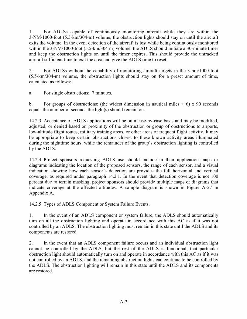
A-2
1. For ADLSs capable of continuously monitoring aircraft while they are within the 3-NM/1000-foot (5.5-km/304-m) volume, the obstruction lights should stay on until the aircraft exits the volume. In the event detection of the aircraft is lost while being continuously monitored within the 3-NM/1000-foot (5.5-km/304 m) volume, the ADLS should initiate a 30-minute timer and keep the obstruction lights on until the timer expires. This should provide the untracked aircraft sufficient time to exit the area and give the ADLS time to reset. 2. For ADLSs without the capability of monitoring aircraft targets in the 3-nm/1000-foot (5.5-km/304-m) volume, the obstruction lights should stay on for a preset amount of time, calculated as follows: a. For single obstructions: 7 minutes. b. For groups of obstructions: (the widest dimension in nautical miles + 6) x 90 seconds equals the number of seconds the light(s) should remain on. 14.2.3 Acceptance of ADLS applications will be on a case-by-case basis and may be modified, adjusted, or denied based on proximity of the obstruction or group of obstructions to airports, low-altitude flight routes, military training areas, or other areas of frequent flight activity. It may be appropriate to keep certain obstructions closest to these known activity areas illuminated during the nighttime hours, while the remainder of the group’s obstruction lighting is controlled by the ADLS. 14.2.4 Project sponsors requesting ADLS use should include in their application maps or diagrams indicating the location of the proposed sensors, the range of each sensor, and a visual indication showing how each sensor’s detection arc provides the full horizontal and vertical coverage, as required under paragraph 14.2.1. In the event that detection coverage is not 100 percent due to terrain masking, project sponsors should provide multiple maps or diagrams that indicate coverage at the affected altitudes. A sample diagram is shown in Figure A-27 in Appendix A. 14.2.5 Types of ADLS Component or System Failure Events. 1. In the event of an ADLS component or system failure, the ADLS should automatically turn on all the obstruction lighting and operate in accordance with this AC as if it was not controlled by an ADLS. The obstruction lighting must remain in this state until the ADLS and its components are restored. 2. In the event that an ADLS component failure occurs and an individual obstruction light cannot be controlled by the ADLS, but the rest of the ADLS is functional, that particular obstruction light should automatically turn on and operate in accordance with this AC as if it was not controlled by an ADLS, and the remaining obstruction lights can continue to be controlled by the ADLS. The obstruction lighting will remain in this state until the ADLS and its components are restored.

A-3/A-4
3. Complete light failure should be addressed in accordance with Chapter 2 paragraph 2.4. 14.2.6 The ADLS’s communication and operational status shall be checked at least once every 24 hours to ensure both are operational. 14.2.7 The ADLS should be able to detect an aircraft with a cross-sectional area of 1 square meter or more within the volume, as required in subparagraphs 14.2.1 1 and 14.2.1 2. 14.2.8 Each ADLS installation should maintain a log of activity data for a period of no less than the previous 15 days. This data should include, but not be limited to, the date, time, duration of all system activations/deactivations, track of aircraft activity, maintenance issues, system errors, communication and operational issues, lighting outages/issues, etc. 14.2.9 Operational Frequencies. 1. Unlicensed devices (including FCC Part 15) devices cannot be used for this type of system. 2. Any frequency used for the operation of ADLS must be individually licensed through the FCC. 14.3 Voice/Audio Option. 14.3.1 ADLS may include an optional voice/audio feature that transmits a low-power, audible warning message to provide pilots additional information on the obstruction they are approaching. 14.3.2 The audible transmission should be in accordance with appropriate FAA and FCC regulations. 14.3.3 The audible transmission should be over an aviation frequency licensed by the FCC and authorized under the Code of Federal Regulations Title 47- Part 87.483 (excluding 121.5 MHz). Note: Using air traffic control frequencies in the 117.975-MHz to 137-MHz frequency band is prohibited for this operation. 14.3.4 The audible message should consist of three quick tones, followed by a verbal message that describes the type of obstruction the system is protecting. Appropriate terms to be used include tower(s), wind turbine(s), or power line(s). 14.3.5 The audible message should be repeated three times or until the system determines the aircraft is no longer within the audible warning area defined in the following paragraph. 14.3.6 The audible message should be considered as a secondary, final warning and should be activated when an aircraft is within 1/2 NM (926 m) horizontally and 500 feet (152 m) vertically of the obstruction. The use of, or variation to, the audible warning zone may occur, depending on site-specific conditions or obstruction types.
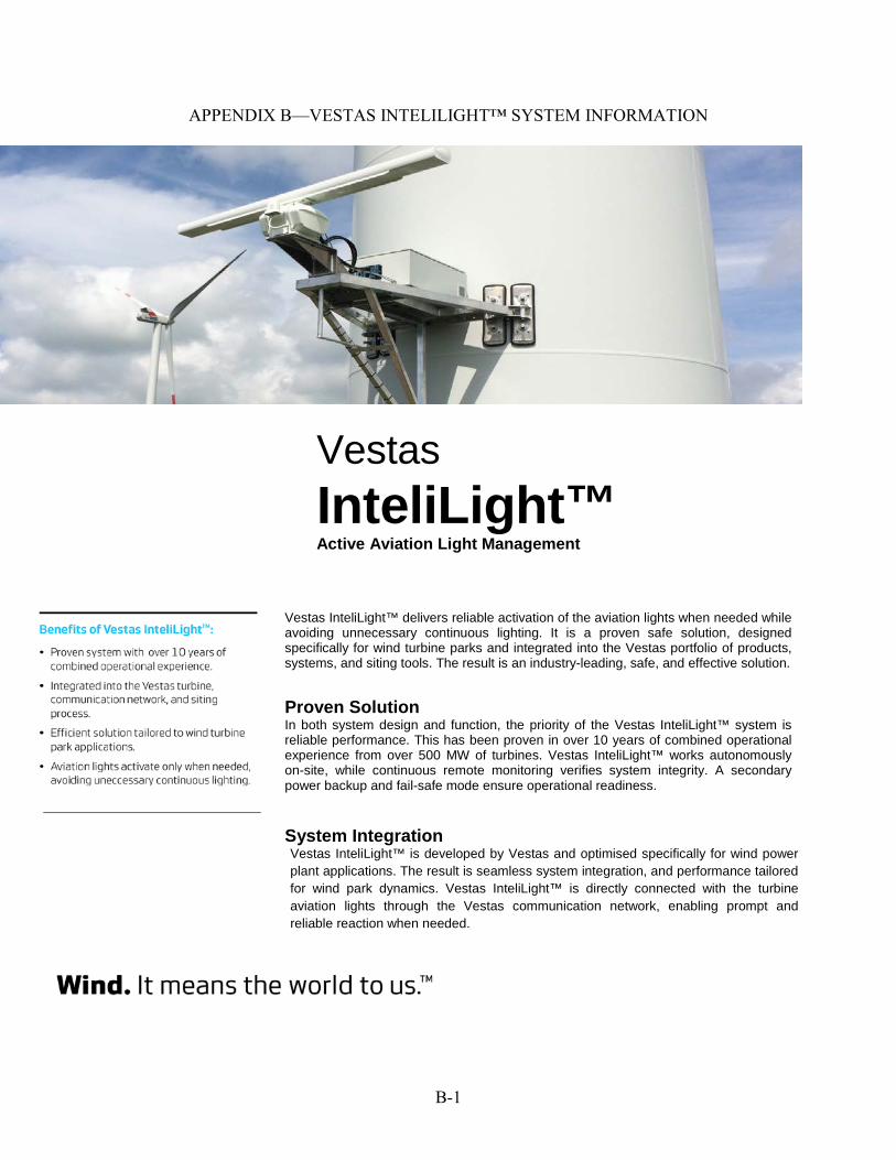
B-1
APPENDIX B—VESTAS INTELILIGHT™ SYSTEM INFORMATION
Vestas InteliLight™ Active Aviation Light Management
Vestas InteliLight™ delivers reliable activation of the aviation lights when needed while avoiding unnecessary continuous lighting. It is a proven safe solution, designed specifically for wind turbine parks and integrated into the Vestas portfolio of products, systems, and siting tools. The result is an industry-leading, safe, and effective solution.
Proven Solution In both system design and function, the priority of the Vestas InteliLight™ system is reliable performance. This has been proven in over 10 years of combined operational experience from over 500 MW of turbines. Vestas InteliLight™ works autonomously on-site, while continuous remote monitoring verifies system integrity. A secondary power backup and fail-safe mode ensure operational readiness.
System Integration Vestas InteliLight™ is developed by Vestas and optimised specifically for wind power plant applications. The result is seamless system integration, and performance tailored for wind park dynamics. Vestas InteliLight™ is directly connected with the turbine aviation lights through the Vestas communication network, enabling prompt and reliable reaction when needed.
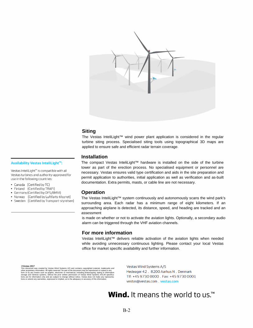
B-2
Siting The Vestas InteliLight™ wind power plant application is considered in the regular turbine siting process. Specialised siting tools using topographical 3D maps are applied to ensure safe and efficient radar terrain coverage.
Installation The compact Vestas InteliLight™ hardware is installed on the side of the turbine tower as part of the erection process. No specialised equipment or personnel are necessary. Vestas ensures valid type certification and aids in the site preparation and permit application to authorities, initial application as well as verification and as-built documentation. Extra permits, masts, or cable line are not necessary.
Operation The Vestas InteliLight™ system continuously and autonomously scans the wind park’s surrounding area. Each radar has a minimum range of eight kilometers. If an approaching airplane is detected, its distance, speed, and heading are tracked and an assessment is made on whether or not to activate the aviation lights. Optionally, a secondary audio alarm can be triggered through the VHF aviation channels.
For more information Vestas InteliLight™ delivers reliable activation of the aviation lights when needed while avoiding unnecessary continuous lighting. Please contact your local Vestas office for market specific availability and further information.
This document was created by Vestas Wind Systems A/S and contains copyrighted material, trademarks and other proprietary information. All rights reserved. No part of the document may be reproduced or copied in any form or by any means such as graphic, electronic or mechanical, including photocopying, taping or information storage and retrieval systems, without the prior written permission of Vestas Wind Systems A/S.All specifica- tions are for information only and are subject to change without notice. Vestas does not make any representa- tions or extend any warranties, expressed or implied, as to the adequacy or accuracy of this information.
©Vestas 2017