Embed Size (px)
Citation preview
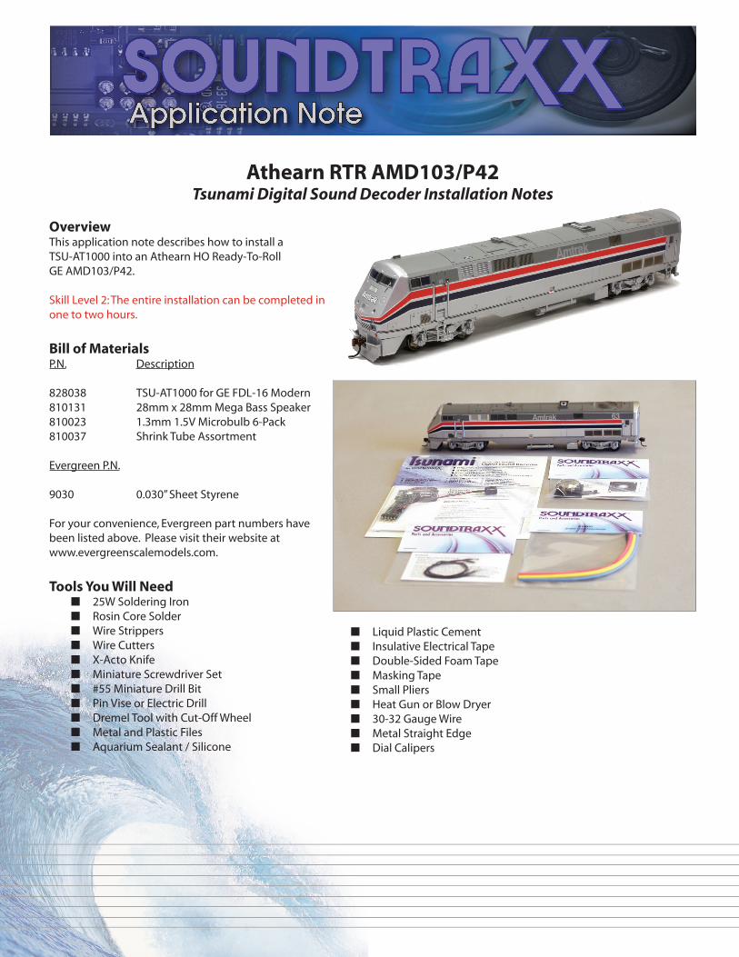
Athearn RTR AMD103/P42Tsunami Digital Sound Decoder Installation Notes
OverviewThis application note describes how to install a TSU-AT1000 into an Athearn HO Ready-To-Roll GE AMD103/P42.
Skill Level 2: The entire installation can be completed in one to two hours.
Bill of MaterialsP.N. Description
828038 TSU-AT1000 for GE FDL-16 Modern810131 28mm x 28mm Mega Bass Speaker810023 1.3mm 1.5V Microbulb 6-Pack810037 Shrink Tube Assortment
Evergreen P.N.
9030 0.030” Sheet Styrene
For your convenience, Evergreen part numbers have been listed above. Please visit their website at www.evergreenscalemodels.com.
Tools You Will Need■ 25W Soldering Iron■ Rosin Core Solder■ Wire Strippers■ Wire Cutters■ X-Acto Knife■ Miniature Screwdriver Set■ #55 Miniature Drill Bit■ Pin Vise or Electric Drill■ Dremel Tool with Cut-Off Wheel■ Metal and Plastic Files■ Aquarium Sealant / Silicone
■ Liquid Plastic Cement■ Insulative Electrical Tape■ Double-Sided Foam Tape■ Masking Tape■ Small Pliers■ Heat Gun or Blow Dryer■ 30-32 Gauge Wire■ Metal Straight Edge■ Dial Calipers

4. Once all wires have been disconnected, remove the board. There is a clip on the bottom of the board that snaps onto a second clip on top of the motor. This clip also acts as the motor positive (M+) lead. Unsnap the top clip to remove the board. (Photo 3)
5. After the circuit board has been removed, the M+ lead will need to be replaced. On top of the motor there is a copper clip, which should carefully be removed because there is a small spring residing below. Using a small pair of pliers, grasp the long end of the clip (indicated by the arrow in the photo) and slowly twist up and away from the mounting so that the spring slowly decompresses and does not fl y up from the model. (Photos 4 and 5)
Installation
1. Begin with removing the couplers and coupler boxes. Unscrew the center screws of the boxes and gently pull the coupler boxes from each end.
2. The shell should lift off easily. Take care when removing the shell since the wires for the front and rear headlights are connected to the light board that is attached to the top of the motor. (Photo 1)
3. Remove the small black clips attached to the ‘light board’ that hold the wires in place. Be sure to note the function of each wire. Labeling with masking tape will make reassembly much easier later. (Photo 2)
Photo 1
Photo 2
Photo 3
Photo 4
Photo 5

9. Steps 9 through 11 are recommended to ensure the reliable operation of the decoder. Remove the motor by removing the four screws under the body that hold the motor mounts to the frame. Once the motor is lifted out, the drivelines will pull out from the fl ywheels. (photos 9 and 10)
10. Note that the bottom of the motor is an uninsulated clip, which is separated from the frame by a small air gap. If this gap is bridged, the decoder will be damaged. To ensure that this will not happen, place a small strip of electrical insulative tape along the bottom of the frame as shown. This will guarantee the motor is fully insulated from the frame. (Photo 11)
11. Reinstall the motor in the frame. Be sure to insert the drive shafts into the fl ywheels before reinstalling the screws for the motor mounts.
6. Solder a 3” piece of 30-32 gauge wire to the top of the clip so that it extends over the long end. (Photo 6)
7. After soldering the wire on, wrap the connection with insulative tape to protect the connection. Be sure the area where the spring contacts the clip is not covered with tape, or the motor will not function. (Photo 7)
8. Once done, remount the clip to the motor. (Photo 8)
Photo 8
Photo 9
Photo 7
Photo 10
Photo 6
Photo 11

12. To allow clearance for the speaker, the rear truck has to be modifi ed. Remove the truck for best results. To do this, gently pry up on the top retainer clip for the worm gear and it will pop off. Lift out the worm gear and the driveline will follow. Set this aside for now. The truck will then fall out from underneath. (Photo 12)
13. To make the clearance, the “?” shaped bracket will need to be removed. Put tape over the open parts of the gearbox to ensure no metal fi lings will get inside. Using a Dremel cut-off wheel, cut the bracket even with the driveline. File to clean up any hazardous fl ashing.
14. File gently on the inside of this bracket to allow the solder to more easily attach to this bracket. Solder a 4” piece of 30-32 gauge wire to the inside of the truck pickup bracket. Reinstall the truck reversing the removal process. (Photo 13)
15. After these wires have been attached to the decoder, mount the decoder to the top of the motor using a piece of double-sided foam tape. (Photos 14 and 15)
16. Next attach the track pickup wires to the Tsunami decoder following the wiring diagram located at the end of this document. These leads attach to the outer tabs on each end of the board. While it is possible to use the clips to reattach the wires to the decoder, we recommend these be soldered for a more reliable connection.
17. Attach the two motor leads to the decoder. The wire that was attached in Step 6 goes to the M+ tab, while the wire that comes up from the bottom of the motor attaches to the M- tab. Note: there is only one negative track wire on this model.
18. Now, test the locomotive and decoder by placing the locomotive on the mainline, selecting address 3, and running forward and backward. There will be no sound or lights yet, but any motor problems can be caught and corrected now.
19. These models do not come equipped with operating ditch lamps. If you do not wish to add ditch lamps, skip ahead to Step 23. To add operating ditch lamps, press out the clear plastic insert that comes installed in the holes for the ditch lamps. Photo 13
Photo 14
Photo 15
Photo 12

20. Shorten one lead of each of the two microbulbs to 1”. Strip off 1/8” of insulation on each wire and off one of the just-cut pieces of wire. Twist the three wires together and solder together to create a Y ‘branch’. Insulate this connection using a 1/4” piece of 1/8” heat-shrink tubing. (Photo 16)
21. Place a small strip of masking tape across the front on the outside of the locomotive. This will help position the lamps fl ush with the front of the model.
22. Insert the bulbs into the holes for the ditch lamps and secure in place by applying silicone on the inside of the shell. Tape the wires down so that the lights do not accidentally come loose while drying. Allow the silicone to fully cure for 24 hours before moving on. (Photo 17)
23. While the silicone is drying, move to the installation of the Mega Bass speaker. Start by soldering two 6” pieces of 30-32 gauge wire to the terminals on the speaker. Since we are using only one speaker, polarity is not important. (Photo 18)
24. Next, cut the sides and top for the styrene baffl e following the template at the end of this document.
25. Using liquid plastic cement, secure the styrene pieces around the sides of the speaker. Thread the wires through the two mounting holes marked on the face of the speaker. (Photos 19 and 20)
26. Secure the top of the baffl e to the model using liquid plastic cement. At this time, fi le or sand the joints smooth for a better fi t. (Photo 21)
Photo 19 Photo 20
Photo 18
Photo 21
Photo 17
Photo 16

27. After the silicone on the ditch lamps has fully dried, line the top inside of the shell with double-sided foam tape to mount the speaker. (Photo 22)
28. This model uses 1.5V bulbs, so they should be wired to the 1.5V common instead of the 12V common tab on each end of the decoder. This eliminates the need for dropping resistors. The 1.5V common is clearly marked on the decoder with ‘1.5V’ next to the small soldering pad. To avoid attempting to solder fi ve wires into this small hole, the wires will need to be combined into two separate ‘branches,’ much like the one created earlier for the ditch lamps. First cut two 3” pieces of 30-32 gauge wire. Take one lead from each of the headlight bulbs and solder to one of the 3” pieces of wire. Slide over a 1/4” piece of 1/8” heat-shrink tubing and heat to insulate the connection.
29. The last ‘branch’ is created by taking one lead from each of the backup light bulbs and soldering to a second 3” piece of 30-32 gauge wire. Slide over a 1/4” piece of 1/8” heat-shrink tubing and heat to insulate the connection.
30. Solder the three branches (headlight, backup light, and ditch lamps) to the 1.5V common soldering pad (three wires to one).
31. Solder the remaining two headlight wires to tab 3 on the decoder. Solder the remaining two wires from the backup lights to tab 8. Solder the remaining lead from one ditch lamp to FX5 and the other remaining wire from the other ditch lamp to FX6. (Photo 23)
32. Peel off the other side of the double-sided foam tape and press the speaker in to secure in place. Take care not to press on the speaker cone as this will damage the speaker. (Photo 24)
33. Solder the speaker wires to the S+ and S- terminals. Since only one speaker is used polarity is not important. (Photo 25)
34. Test run the locomotive on the mainline to ensure that all lights and sound operate properly. After passing all tests, be sure the wires tuck up into the shell and replace the shell over the frame. Test again to ensure all wires are not interfering with the drive train. After passing the test, reinstall the couplers.
Photo 23
Photo 24
Photo 22
Photo 25

Programming Notes: For alternating ditch lamps when the horn is blown, set CV 51 to 41 and CV 52 to 57. For F5 to activate both ditch lamps, set CV 39 to 6 and CV 40 to 0. For F6 to activate ditch lamps, set CV 39 to 0 and CV 40 to 6. For the K5LA horn set CV 115 to 8.
Baffl e Dimensions
0.5”
1.1” 1.16” 0.5”
1.16”
1.16”
TSU-AT1000 Wiring Diagram
TM
New Dimensions in Digital Sound Technology
©2013 Throttle Up! Corp.All Rights Reserved
Front Right Pickup
Front Left Pickup
RearRight Pickup
RearLeft Pickup
Motor
Function Common Function Common
Headlight Backup Light
1 2 3 4
107
8
9
FWD
REV ALED25 6
Motor -
Motor +
S+ S-
1.5V Common
Ditch Lamps
141 Burnett Drive • Durango, CO 81301Phone: (970) 259-0690 • Toll Free: 888-789-7637 • Fax: (970) 259-0691
Email: [email protected] • Website:www.soundtraxx.com