Embed Size (px)
Citation preview

The tikz timing Package
A LATEX Package for Timing Diagrams
Version v0.7d – 2011/01/09
Martin [email protected]
WWW: http://latex.scharrer-online.de/tikz-timing
CTAN: http://www.ctan.org/pkg/tikz-timing

Contents1 Introduction 5
1.1 Changelog . . . . . . . . . . . . . . . . . . . . . . . . . . . . . . . . . . . . . . . . . . . . . . . . . . . . . . . 61.2 Dependencies . . . . . . . . . . . . . . . . . . . . . . . . . . . . . . . . . . . . . . . . . . . . . . . . . . . . . 9
2 Usage 102.1 Timing Characters . . . . . . . . . . . . . . . . . . . . . . . . . . . . . . . . . . . . . . . . . . . . . . . . . . 102.2 Macro for use in Text Mode . . . . . . . . . . . . . . . . . . . . . . . . . . . . . . . . . . . . . . . . . . . . . 132.3 Macro for use inside TikZ-Pictures . . . . . . . . . . . . . . . . . . . . . . . . . . . . . . . . . . . . . . . . . 142.4 Table for Timing Diagrams . . . . . . . . . . . . . . . . . . . . . . . . . . . . . . . . . . . . . . . . . . . . . . 162.5 Macros for use inside the Character String . . . . . . . . . . . . . . . . . . . . . . . . . . . . . . . . . . . . . 212.6 Meta-Characters . . . . . . . . . . . . . . . . . . . . . . . . . . . . . . . . . . . . . . . . . . . . . . . . . . . 23
3 TikZ Keys for Styles, Settings and Actions 26
4 Libraries for Further Characters 304.1 arrows . . . . . . . . . . . . . . . . . . . . . . . . . . . . . . . . . . . . . . . . . . . . . . . . . . . . . . . . . 314.2 either . . . . . . . . . . . . . . . . . . . . . . . . . . . . . . . . . . . . . . . . . . . . . . . . . . . . . . . . . . 324.3 overlays . . . . . . . . . . . . . . . . . . . . . . . . . . . . . . . . . . . . . . . . . . . . . . . . . . . . . . . . 334.4 clockarrows . . . . . . . . . . . . . . . . . . . . . . . . . . . . . . . . . . . . . . . . . . . . . . . . . . . . . . 344.5 columntype . . . . . . . . . . . . . . . . . . . . . . . . . . . . . . . . . . . . . . . . . . . . . . . . . . . . . . 354.6 nicetabs . . . . . . . . . . . . . . . . . . . . . . . . . . . . . . . . . . . . . . . . . . . . . . . . . . . . . . . . 364.7 counters . . . . . . . . . . . . . . . . . . . . . . . . . . . . . . . . . . . . . . . . . . . . . . . . . . . . . . . . 374.8 advnodes . . . . . . . . . . . . . . . . . . . . . . . . . . . . . . . . . . . . . . . . . . . . . . . . . . . . . . . . 404.9 ifsym . . . . . . . . . . . . . . . . . . . . . . . . . . . . . . . . . . . . . . . . . . . . . . . . . . . . . . . . . . 434.10 interval . . . . . . . . . . . . . . . . . . . . . . . . . . . . . . . . . . . . . . . . . . . . . . . . . . . . . . . . . 444.11 beamer . . . . . . . . . . . . . . . . . . . . . . . . . . . . . . . . . . . . . . . . . . . . . . . . . . . . . . . . . 45
2

5 Examples 47
3
List of Examples
1 Initial Characters, Modifiers, TikZ Keys . . . . . . . . . . . . . . . . . . . . . . . . . . . . . . . . . . . . . . 482 tikztimingtable without extracode . . . . . . . . . . . . . . . . . . . . . . . . . . . . . . . . . . . . . . . . . . 493 tikztimingtable with extracode . . . . . . . . . . . . . . . . . . . . . . . . . . . . . . . . . . . . . . . . . . . . 494 timing inside general tikzpicture . . . . . . . . . . . . . . . . . . . . . . . . . . . . . . . . . . . . . . . . . . . 505 Using In-Line Nodes to draw Relationships. . . . . . . . . . . . . . . . . . . . . . . . . . . . . . . . . . . . . 506 Using In-Line Nodes to draw Marker Lines. . . . . . . . . . . . . . . . . . . . . . . . . . . . . . . . . . . . . . 517 Adjusting Diagram Parameters and using Advanced In-Line Nodes to draw Marker Lines. . . . . . . . . . . . 528 SR flip-flop timing diagram . . . . . . . . . . . . . . . . . . . . . . . . . . . . . . . . . . . . . . . . . . . . . 539 SPI Interface Timing . . . . . . . . . . . . . . . . . . . . . . . . . . . . . . . . . . . . . . . . . . . . . . . . . 54
4
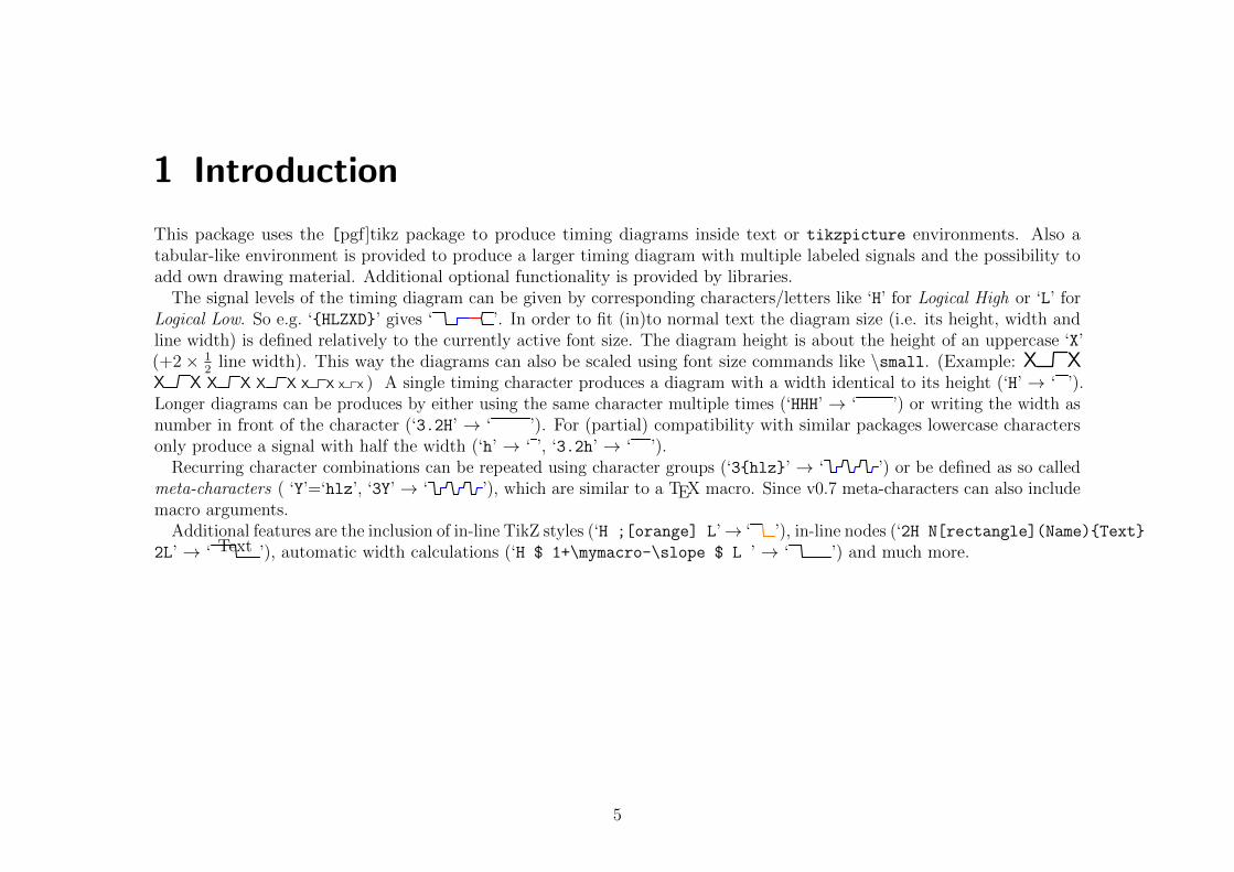
1 Introduction
This package uses the [pgf]tikz package to produce timing diagrams inside text or tikzpicture environments. Also atabular-like environment is provided to produce a larger timing diagram with multiple labeled signals and the possibility toadd own drawing material. Additional optional functionality is provided by libraries.
The signal levels of the timing diagram can be given by corresponding characters/letters like ‘H’ for Logical High or ‘L’ forLogical Low. So e.g. ‘{HLZXD}’ gives ‘ ’. In order to fit (in)to normal text the diagram size (i.e. its height, width andline width) is defined relatively to the currently active font size. The diagram height is about the height of an uppercase ‘X’(+2× 1
2line width). This way the diagrams can also be scaled using font size commands like \small. (Example: X X
X X X X X X X X X X ) A single timing character produces a diagram with a width identical to its height (‘H’ → ‘ ’).Longer diagrams can be produces by either using the same character multiple times (‘HHH’ → ‘ ’) or writing the width asnumber in front of the character (‘3.2H’ → ‘ ’). For (partial) compatibility with similar packages lowercase charactersonly produce a signal with half the width (‘h’ → ‘ ’, ‘3.2h’ → ‘ ’).
Recurring character combinations can be repeated using character groups (‘3{hlz}’ → ‘ ’) or be defined as so calledmeta-characters ( ‘Y’=‘hlz’, ‘3Y’ → ‘ ’), which are similar to a TEX macro. Since v0.7 meta-characters can also includemacro arguments.
Additional features are the inclusion of in-line TikZ styles (‘H ;[orange] L’→ ‘ ’), in-line nodes (‘2H N[rectangle](Name){Text}
2L’ → ‘ Text ’), automatic width calculations (‘H $ 1+\mymacro-\slope $ L ’ → ‘ ’) and much more.
5
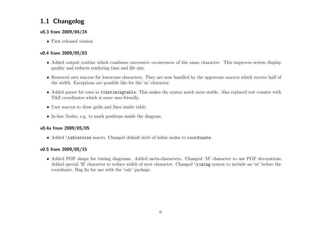
1.1 Changelog
v0.3 from 2009/04/24
• First released version
v0.4 from 2009/05/03
• Added output routine which combines successive occurrences of the same character. This improves screen displayquality and reduces rendering time and file size.
• Removed own macros for lowercase characters. They are now handled by the uppercase macros which receive half ofthe width. Exceptions are possible like for the ‘m’ character.
• Added parser for rows in tikztimingtable. This makes the syntax much more stable. Also replaced row counter withTikZ coordinates which is more user-friendly.
• User macros to draw grids and lines inside table.
• In-line Nodes, e.g. to mark positions inside the diagram.
v0.4a from 2009/05/05
• Added \tablerules macro. Changed default style of inline nodes to coordinate.
v0.5 from 2009/05/15
• Added PGF shape for timing diagrams. Added meta-characters. Changed ‘M’ character to use PGF decorations.Added special ‘B’ character to reduce width of next character. Changed \timing syntax to include an ‘at’ before thecoordinate. Bug fix for use with the ‘calc’ package.
6

v0.6 from 2009/07/27
• Added “forward” modifier ‘F’ as reverse version of the “backward” modifier ‘B’.
• Added support for lower-case modifiers “b’, ‘f’ and n’.
• Added libaries for characters ‘A’/‘W’ for arrows and ’E’ for uncertain low-to-high and high-to-low transitions.
v0.6a from 2009/07/28
• Added library for overlay modifier ‘O’.
v0.7 from 2009/12/05
• New libraries:
clockarrows Library for clock arrows.
columntype Library providing a timing column type for tabular.
nicetabs Library to format \tikztimingtable like a booktab tabular.
counters Library to defined counter characters which display an incrementing counter value every time there are used.
advnodes Library for advanced nodes with multiple anchor points.
ifsym Library providing the same timing symbols and characters as the ifsym package when loaded with the electronicoption.
• Additional experimental libraries:
interval Library to change color of ‘ZL’, ‘ZH’ etc. transitions to indicate borders of an interval.
beamer Library providing some marginal beamer overlay support.
• overlays library:
– Overlays can now be cascaded, i.e. an overlay can be inside another one.
– The second braces around the second part are now optional.
7

– Fixed issues with ‘T’ and ‘C’ characters inside overlays.
• Meta-characters can now have arguments.
• Added more variety for in-line options: ‘[[ ]]’, ‘[+ +]’ and ‘[| |]’.
• Handling of in-line options and nodes got modified. Options are now placed directly where placed and are valid untilthe next ‘;’. Please note that [/utils/exec={..}] now needs to be written as [|/utils/exec={..}|]. Otherwise itis re-executed every time the drawing path is renewed.
• Added star version of \tablegrid.
• Added background to ‘E’ character (either library).
• Some fixes for placing of ‘D{}’ texts.
• Fixed wrong slopes (e.g. lslope instead of zslope) for some transitions.
• Major changes on internal character definition macros, parser and output routine.
• Fixed problems with expanding code content in user input.
• The \texttiming macro now uses a \timing macro internally.
• The \timing macro is now only defined inside tikzpictures. This includes tikztimingtable.
• Added TikZ style timing/draw grid for grids behind \timing macros.
• Replaced macros \texttimingbefore, \texttimingafter and \texttiminggrid with TikZ settings ‘timing/before text’,‘timing/after text’ and ‘timing/draw grid’.
• Added separators ‘timing/outer sep’ around \texttiming.
• Graphical improvements for ‘double line’ characters like ‘D’, ‘U’ and ‘E’. The whole character including both edges isdrawn in a single process.
• Character width can now be scaled using wscale.
8

• Character width can now be calculated by placing code inside ‘$ $’.
• Fixed issue with \horlines macro.
• The tikztimingtable environment and associated macros got enhanced:
– The content is no longer read as macro argument and can now include paragraphs.
– Multiple extracode sections can be now included between rows, not only a single section at the very end.
– A extracode environment has been added. Both macro and environment have now an optional argument for TikZsettings.
– Added \tableheader macro to label both columns. The \tablerules macro got adjusted to detect the headerline and draw also a middle line.
– Added background environment to draw things in the background.
– Fixed broken optional argument of \tablegrid.
– Added macro \marknodes and associated debug/nodes style to mark in-line nodes for debug purposes/orientationduring the diagram creation.
v0.7d from 2011/01/09
• Fix for end macro of extracode environment to support etoolbox’s environment hooks.
1.2 Dependencies
. . .
9
2 Usage
2.1 Timing Characters
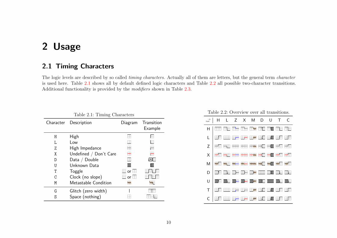
The logic levels are described by so called timing characters. Actually all of them are letters, but the general term characteris used here. Table 2.1 shows all by default defined logic characters and Table 2.2 all possible two-character transitions.Additional functionality is provided by the modifiers shown in Table 2.3.
Table 2.1: Timing Characters
Character Description Diagram TransitionExample
H HighL LowZ High ImpedanceX Undefined / Don’t CareD Data / Double A
U Unknown DataT Toggle orC Clock (no slope) orM Metastable Condition
G Glitch (zero width)S Space (nothing)
Table 2.2: Overview over all transitions.
tofrom H
H
L
L
Z
Z
X
X
M
M
D
D
U
U
T
T
C
C
10

Table 2.3: Modifiers for Timing Characters.
Modifier Syntax Description
D{}D Produces transition between two data values. E.g.: ‘D{}D’ →D{〈Text〉} Adds 〈text〉 into a data signal using a node. E.g.: ‘D{A}D{B}’ → A B
D{[〈 TikZSettings〉]〈Text〉} Adds 〈text〉 using the given node 〈settings〉. E.g.: ‘D{[blue]A}’ → A
〈number〉〈character〉 Sets width of next signal to given number. Half of it if character is in lower case. E.g.: ‘2.6H5.2l’ →〈integer〉{〈characters〉} Repeats the given characters 〈int〉 times. E.g.: ‘5{hl}’ →{ 〈characters〉 } Encloses characters in a local scope. Options inside are only local to the scope. This also applies to the effect of
‘;’ and similar modifiers. E.g.: ‘H {[blue] LH} L’ →
〈number〉B Subtracts the given number from the width of the next character. “Backwards” E.g.: ‘H.5BL’ →〈number〉F Adds the given number to the width of the next character. “Forwards” E.g.: ‘H.5FL’ →N[〈Settings〉](〈Name〉){〈Content〉} Adds node at current position. All three arguments are optional. E.g.: ‘H N(a1) L’ →
[〈TikZ Keys〉] Executes given TikZ settings during the drawing process. This settings will be re-executed when the internaldrawing path is renewed which can cause side-effects. E.g.: ‘H[blue]LH’ →
[|〈TikZ Keys〉|] Executes given TikZ settings during the drawing process like [ ] but does not re-executes them.E.g.: ‘D{.} [|/utils/exec={\def \m {...}}|] D{.} D{.}’ → . . .
[!〈TikZ Keys〉!] Executes given TikZ settings during the parsing process. Because this makes only sense for internal settings thedefault path is ‘/tikz/timing’, not ‘/tikz’ like in all other settings macros.E.g.: ‘H[!wscale=2.5!]LH’ →
[[〈TikZ Keys〉]] Executes given TikZ settings first during the parsing process and again during the drawing process. This is forsettings which are needed for width calculations and again for the drawing code, e.g. the slope values.E.g.: ‘H[[timing/slope=.5]]L $\slope $H’ →
!{〈code〉} Places given code into the internal tikzpicture. See Example 1.@{〈code〉} Executes the given code immediately during the parsing process. This can be used to change parsing
parameters. To execute code during the drawing process use [|/utils/exec=〈code〉|] instead.E.g.: ‘L @{\setwscale {2}} H’ →
11

Table 2.3 – continued from previous page
Modifier Syntax Description
$〈math expression〉$ Takes a valid pgfmath expression (See pgf manual), evaluates it and places the result back in the input stringso it can be used as width for the next character. The macros \slope=\lslope, \dslope, \zslope and\wscale can be used to access the corresponding values. E.g.: ‘D{} $ \dslope $ D{} D’ →
; Renews the internal drawing path which ends the scope of all options given by [ ].E.g.: ‘H;[blue]L;H’ →
, Same as ‘;’, but timing specific options (atm.: slopes and line width) are restored for the new path.E.g.: ‘[line width=1pt]L,H;L’ →
12

2.2 Macro for use in Text Mode
\texttiming[〈initial character/TikZ Settings〉]{〈characters〉}
This macro places a single timing diagram line into the current text. The signals have the same height as a uppercaseletter (like ‘X’) of the current font, i.e. they scale with the font size. The macro argument must contain only valid logiccharacters and modifiers which define the logical levels of the diagram line.
An initial character can be given as an optional argument. No logic level will be drawn for this character. Instead it will beused to define the initial position of the signal so that the diagram line will start with a transition from the initial to the firstcharacter. However, if the optional argument holds more than a single character it is taken as TikZ settings for the diagram.The initial character can then be given using the key ‘timing/initchar=〈char〉’.Examples:\texttiming{HLZDZLH} gives ‘ ’, with grid: ‘ ’.\texttiming[L]{HLZDZLH} gives ‘ ’, with grid: ‘ ’.\texttiming[green]{HLZDZLH} gives ‘ ’\texttiming[green,timing/initchar=L]{HLZDZLH} gives ‘ ’
\texttimingbefore Deprecated! (defaults to : 〈empty〉)\texttimingafter Deprecated! (defaults to : 〈empty〉)
This two macros are executed before and after every timing diagram line created by \texttiming macro inside the sametikzpicture environment and can be used to add drawing macros. The argument of the \texttiming macro is alreadyprocessed before any of these macros are expanded, therefore this macros can access the width of the diagram.
These macros should not be used directly in newer code but instead the new TikZ styles ‘timing/before text’ and‘timing/after text’. For backward compatibility these styles default to the two macros.
(Deprecated) Example: \let\texttimingbefore\texttiminggrid adds a grid into the background of the \texttiming diagram.
\texttiminggrid Deprecated!
This macro should only be used inside \texttimingbefore or \texttimingafter and draws a grid of the full size of the\texttiming diagram. For newer code the TikZ styles ‘timing/draw grid’ and ‘timing/no grid’ should be used instead,e.g. \tikzset{timing/intext/.append style={timing/draw grid}} or simply enable the grid globally for all in-text andother timing diagrams with \tikzset{timing/draw grid}.
13
2.3 Macro for use inside TikZ-Pictures
\timing[〈TikZ Keys〉] at (〈TikZ Coordinate〉) {[〈initial character〉]〈characters〉};
This macro does the same as \texttiming but is designed to be used inside a tikzpicture environment and only there.Like normal TikZ macros (\path, \drawn, \node) it allows an optional argument with TikZ settings and an optionalTikZ-coordinate. However, a own argument parser, not the one used by TikZ, is used to detect and read these optionalarguments. Therefore the order of the arguments is mandatory and must not be reversed. This small limitation might beovercome in future versions of this package.
Please note that the optional initial character may be given inside and at the very start of the mandatory argument, notbefore it. This is necessary because of several technical reasons.
Example: \tikz \timing [green] at (1,2) {HLZDZLH}; gives ‘ ’.Example: \tikz \timing [green] at (1,2) {[L]HLZDZLH}; gives ‘ ’.
14

Timing Shape Anchors
Every timing diagram line produced by \timing, which includes the rows in tikztimingtable, is also a PGF shape (node)with several anchors. These are shown in Figure 2.1. The shape is very similar to the standard rectangle shape but doesnot provide a text anchor. In addition to the standard points of the compass anchors of TikZ the three logic levels low, midand high can be used in combination with start, mid and end. An extra origin anchor is located at the lower left, alsocalled south west corner where the diagram originates. The two anchors called start and end are provided to mark thestart and end of the timing signal. There are either located at the low, middle or high logic level dependent on the used first(or initial) and last timing character.
In order to use the timing node it has to be named which can be done using the ‘name=〈name〉’ option inside the optionalargument. The rows of a tikztimingtable are automatically named as ‘row〈row number〉’ where the first row has thenumber 1.
(s.north west) (s.north) (s.north east)
(s.west) (s.center) (s.east)(s.mid west) (s.mid) (s.mid east)
(s.base west) (s.base)(s.base east)
(s.south west) (s.south) (s.south east)(s.low start)
(s.mid start)
(s.high start)
(s.low mid)
(s.high mid)
(s.low end)
(s.mid end)
(s.high end)
(s.start)
(s.end)(s.origin)
Figure 2.1: Timing Shape Anchors. The start and end anchors mark the start and end of the timing signal.
15

2.4 Table for Timing Diagrams
\begin{tikztimingtable}[〈TikZ settings for whole table〉]{〈Signal Name〉} & [〈Init. Char./TikZ Keys for Row〉]〈Characters〉 \\
...
\extracode % Optional
<additional code>
\end{tikztimingtable}
This environment can be used to typeset multi-line timing diagrams. The syntax is like the one for a tabular environmentwith two columns. The first column is for the signal name and the second one are the logic characters which would beplaced inside the argument of a \texttiming or \timing macro. If the second column starts with an optional argument it iseither taken as initial character if it holds only a single character or as row wide settings otherwise. The whole table will bedrawn inside a tikzpicture environment using multiple \timing and \node macros for the timing signals and their names,respectively. Additional tikz drawing code can be insert at the end of the table using \extracode.
\extracode[TikZ Keys]
This macro is only defined inside a tikztimingtable environment. In earlier versions of this package it could only be usedafter the last table line (i.e. after a \\). If used there all code between it and the \end{tikztimingtable} will be placedinside the same tikzpicture. This allows to add some drawing lines or a grid to the picture. The macro does not start aTikZ scope or a TEX group by itself. The optional 〈settings〉 therefore affect all following code until the end of the picture.
It is also possible to draw something behind the timing diagram by using using the background environment or the PGFbackground layer:
\begin{pgfonlayer}{background}. . . \end{pgfonlayer}
\endextracode
From version 0.7 on it is possible to add further timing rows after an extracode section by using \endextracode. Everything New in v0.7
after this macro is taken as part of a new row. It is allowed to use this macro direct before \endtikztimingtable. Thismakes it possible to use \extracode anywhere inside the table, including at the very start before any rows are processed.Early insertion of extra code is necessary for e.g. limiting the bounding box or setting up a clipping path.
16

\begin{extracode}[〈TikZ settings〉]〈extra drawing code〉
\end{extracode}
Instead of using \extracode . . . \endextracode, which is actual plainTEX syntax, this LATEX style environment can be New in v0.7
used. Like any environment it creates a TEX group around its content, but no TikZ scope is created to allow drawing code(e.g. clipping paths) to affect the rest of the table. The optional 〈settings〉, however, only affect the environment content.
Please note that while \endextracode is optional if \extracode is used at the end of the table, a \begin{extracode}
must always be closed by \end{extracode}.
Macros for \extracode Section
The following macros are only defined inside a tikztimingtable after the macro \extracode. They are useful for drawingadditional material.
\tablegrid*[〈TikZ Keys〉]
After \extracode this macro draws a grid in the background of the table. A separate grid is drawn for each row. Thenormal version draws all grids with the width of the widest row while the star version draws them with the width of thecorresponding row. Because this macro draws material into the background layer it must not be placed inside a pgfonlayer
environment itself.
\fulltablegrid[〈TikZ Keys〉]
After \extracode this macro draws a big grid over all rows in the background of the table.
\nrows
Returns the number of rows in the current table. Useful for use in \horlines.
\rowdist
\coldist
This macros return the row and column distance. There are useful for drawing additional material relative to the rows and
17

columns. This values can be set (e.g. in the optional argument of the table) using the timing/rowdist and timing/coldist
settings which are explained in Section 3.
\twidth
Returns the width (as multiple of the ‘period width’) of the longest timing diagram line in the table. Example: If thelongest line would be ‘H 2.3L z’ than \twidth would be 1 + 2.3 + 0.5 = 3.8.
\horlines[〈TikZ Keys〉]{〈list〉}
Draws horizontal lines, optionally with the given 〈Settings〉, at the base line of the rows given by 〈list〉. The PGF macro\foreach1 is internally used so the list can include not only row numbers as integer but also fractional numbers and the ‘...’operator to auto-increment the numbers. Please note that all numbers in the list are multiplied by \rowdist. If the list isempty the default ‘1,2,...,\nrows’ is used which draws lines for all rows.
\vertlines[〈TikZ Keys〉]{〈list〉}
Like \horlines but draws vertical lines and the listed numbers a relative to the basic width. If the list is empty the default‘0,1,...,\twidth’ is used which draws lines after every period width.
\tableheader[〈TikZ Keys〉]{〈Description Title〉}{〈Signal Title〉}
This macro adds a table head row on top of the table. The two mandatory arguments provide the header text for thedescription and signal columns.
\tablerules[〈TikZ Keys〉]
This macro adds top and bottom rules to the table in the same (or at least very similar) way as the booktabs package isdoing it for normal tabulars. The current bounding box is used to calculate the needed rule length, which makes this macroposition dependent if further code changes the bounding box. If the \tableheader macro was used beforehand it also drawsa thinner horizontal line (like booktabs \midrule) between the table head and body.
1See the pgf manual for more details.
18

\begin{background}[〈TikZ Keys〉]〈drawing commands〉
\end{background}
This environment can be used to draw material on the background layer and is an abbreviation for:
\begin{pgfonlayer}{background}
\begin{scope}[〈TikZ Keys〉]〈drawing commands〉
\end{scope}
\end{pgfonlayer}
Scaling the Table
The standard ‘scale’ setting of TikZ will not scale all parts of the table correctly, e.g. the line width and nodes willkeep their original size. However there are scaled relative to the font size. Alternatively the table can be scaled usingthe \scalebox{〈factor〉}{〈content〉} macro from the graphicx package or be placed inside a scaled \node inside anothertikzpicture environment.
Positions & Nodes inside the Table
Coordinates
The first row starts at y = 0 and the next rows are each -1*\rowdist lower than the previous one. The vertical unit is 1signal height and the default row distance is ‘2’ (=2×signal height). This means that a normal table with three rows goes fromy = +1 (base line at 0 + 1 signal height) to y = −4 (first row: +0, second row: -2, third row: -4). This are relative to themiddle of the drawn lines, i.e. the bounding box is 2× line width
2= 1×line width higher.
The timing column starts at x = 0 and goes into the positive range while scaled using the period width. Example: HHHhhas a width of 3.5. The label column starts at x = −\coldist and the text is right align with the right border at thisposition. See Figure 2.2 for an illustration.
19

Nodes
Each timing line is a timing node (see section 2.3) labeled (not fully correctly) as ‘row〈number〉’, where the first row hasthe number 1 and the last one the number provided in \nrows, but can also accessed using the alias ‘last row’. Thecorresponding labels are normal rectangle nodes named ‘label0’, ‘label1’, . . . , ‘label\nrows’/‘last label’.
Both groups of ‘rows’ and ‘labels’ are enclosed in a rectangle node called ‘all rows’ and ‘all labels’, respectively. Thesenodes can be used to draw material relative to the rows, e.g. the macros \tableheader and \tablerules are making use ofthem. The headers added by \tableheader are rectangle nodes names ‘label header’ and ‘row header’ and are placed be-tween the x-coordinates of the inner and outer border of ‘all labels’ and ‘all rows’ respectively. By default the TikZ settings‘pos=0’ and ‘anchor=base east’/‘anchor=base west’, respectively, are applied to place them in the inner border, but this canbe changed using the styles ‘timing/table/header’ and/or ‘timing/table/label header’/‘timing/table/row header’.All nodes are shown in Figure 2.2.
row1
row2
row\nrowslast row
label header row header
0pos1 0 pos 1
all rows
label1
label2
label\nrowslast label
all labels
origin
\rowdist
\yunit\xunit
\coldist
First Row
Second Row... ...
Last Row
Label Timing
Figure 2.2: Distances and Nodes inside a tikztimingtable
20
2.5 Macros for use inside the Character String
The modifiers ‘@’ and ‘$’ allow the user to include macros. These macros are evaluated when the tikz-timing parserencounters them in the input character string, i.e. before any diagram element is drawn or any single bracket ‘[ ]’ options areprocessed. Therefore their values should be set either outside the tikz-timing diagram or with the ‘[! .. !]’ or ‘[[ .. ]]’option blocks.
The following macros are provided for the user.
\tikztimingsetwscale{〈math expression〉}\setwscale{〈math expression〉}
This macro , which can be called \setwscale for short inside modifier code, sets the wscale value. This value is used New in v0.7
during the parsing process to scale the width of the characters, e.g. wscale=3.2 makes 1H as long as 3.2H normally wouldbe. Slopes are not affected, but the ‘width’ values of meta-characters are. It can also be set with the timing/wscale TikZsetting. The current value can be accessed using \wscale.
\wscale
Returns the current width scaling ‘wscale’ value.
\xunit
\yunit
This dimension registers can be used to access the x- and y-unitlength of the timing diagram. Assignments to these registersdo not change the scaling!
\slope
\lslope (alias)
Returns the current logic slope, i.e. the slope between L and H levels. Set by the timing/lslope or indirectly by thetiming/slope TikZ setting. See Table ?? for more information.
\zslope
21

Returns the current Z slope. Set by the timing/zslope or indirectly by the timing/slope TikZ setting.
\dslope
Returns the current Z slope. Set by the timing/dslope or indirectly by the timing/slope TikZ setting.
Examples:
Changing the slope and using its value to calculate the width of a character:\texttiming{ HLHLHL [[timing/slope=.5]] H $\slope$L }
gives:
Changing the width scaling for a curtain group of characters:\texttiming{ HL [!wscale=\wscale/3!] 3D{a} Z D Z [!wscale=3*\wscale!] HL }
gives: a
22

2.6 Meta-Characters
It is possible to define recurring groups of characters and modifiers as so called meta-characters. These characters are thanexpanded to the group whenever they appear inside the character list. Please note that like for groups a numeric factor beforesuch a meta-character is taken as a repetition factor not as a width. The meta-character is case sensitive and the other caseis not affected by the definition, i.e. the lower- and uppercase versions of one character can have complete different meanings.It is possible to redefine normal characters (only one or both cases) as meta-characters, which suppresses its normal meaning.Using the meta-character in its own definition group causes a infinite loop which will lead to an TEX error.
\tikztimingmetachar{〈Meta-Character〉}[〈Number of arguments〉]{〈Character Group〉}
This macro defines the given 〈meta-character〉 to be identical to the given 〈character group〉. Alternatively this can also bedone using the TikZ style ‘timing/metachar={〈Meta-Character〉}[〈Number of arguments〉]{〈Character Group〉}’.
An empty group deletes the meta-character, which might be necessary in cases when normal characters are temporaryredefined as meta-characters. However, if the group only contains spaces the meta-character is practically ignored.
Meta-Characters with Arguments
The replacement text of meta-character can now include macro arguments. This allows the creation of more complex and New in v0.7
flexible meta-characters. The optional argument 〈Number of arguments〉 selects the number of macro arguments in the sameway it does for \newcommand. However, the first argument #1 is always set to the given ‘width’ of the meta-character, i.e. thenumber value preceding it. All further arguments are read as normal for macros from the text after the meta-character. It isrecommended to enclose them in braces.
The default behaviour of meta-character without arguments is, as mentioned above, to repeat the replacement groupby the preceding number (‘width’). This is now archived by defining them internally as ‘#1{〈Character Group〉}’, whichcreates a repetition group. Users which want to include an own argument but still want to repeat the group need to definea meta-character with at least two arguments and define it as ‘#1{ .. #2 .. }’. If the repetition is not wanted the #1
argument can be used as a real width for one or more group internal characters: ‘{Y}[1]{Z #1D Z}’, so ‘4Y’ will give ‘Z 4D Z’instead of ‘4{Z D Z}’.
Also the modifier ‘@’ (see Table 2.3) together with the \setwscale macro can be used to scale the whole group dependenton the first argument:
‘{Y}[1]{ @{\setwscale{#1*\wscale}} Z 2D Z @{\setwscale{\wscale/#1}} }’, so ‘4Y’ is equivalent to ‘4Z 8D 4Z’.
23

The new ‘$’ modifier can be used to calculate the width of the group characters: {Y}[1]{$#1/3$D{A} $#1/3D${B} $#1/3$D{C}},so ‘4Y’ results in ‘1.333D{A} 1.333D{B} 1.333D{C}’.
Examples:
\tikztimingmetachar{Y}{2D 0.5U 2D{}} \texttiming{ZZ Y Z 3Y ZZ}
gives:
\tikztimingmetachar{Y}{2D{Text}} \tikztimingmetachar{y}{1D{\tiny Text}} \texttiming{ZZ Y Z 3y ZZ}
gives: Text Text Text Text
\newcounter{mycount}
\tikztimingmetachar{Q}{2D{\stepcounter{mycount}\arabic{mycount}}}
\tikztimingmetachar{R}{[| /utils/exec=\setcounter{mycount}{0} |]}
\texttiming{ 5Q R 3Q R 10Q }
gives: 1 2 3 4 5 1 2 3 1 2 3 4 5 6 7 8 9 10
Redefining the glitch ‘G’ character:\tikztimingmetachar{G}{.1T.1T .2B} \tikztimingmetachar{g}{.1T.1T}
\texttiming{ 10{H G L G} H } % With correction of width ‘.2B’
\texttiming{ 10{H g L g} H } % Without correction
\texttiming{ 10{H L } H } % For comparison
gives:
\tikztimingmetachar{J}[2]{ 1.8D{#2} .2D{} }
\texttiming{ D{} J{A} J{B} J{C} D }
gives: A B C
\tikztimingmetachar{Y}[3]{#1{ D{\strut #2} D{#3} }}
\texttiming{ Z 2Y{a}{b} Z 4Y{1}{2} Z}
gives: a b a b 1 2 1 2 1 2 1 2
24

\tikztimingmetachar{Y}[3]{ .2D .2B #1d{\strut #2} .2D .2B #1d{\strut #3} }
\texttiming{ Z 2Y{a}{b} Z 4Y{1}{2} Z}
gives: a b 1 2
Mata-chars to set the width scaling. Because the scaling also affects the meta-char width (#1) argument a compensation isneeded to achieve absolute values (W) instead of relative ones (w).\tikztimingmetachar{w}[1]{ [! wscale=#1 !] } % relative
\tikztimingmetachar{W}[1]{ [! wscale=#1/\wscale !] } % absolute
\texttiming{ HL .2w HLHLH 3w LH 1W LH }
gives:
25

3 TikZ Keys for Styles, Settings and Actions
TikZ itself uses the pgfkeys package to define and apply drawing styles and settings. The same method is also used fortikz-timing which places all of the keys under the “subdirectory” ‘timing’ in the main “directory” ‘tikz’, which is thedefault when \tikzset is used. This keys are simply called TikZ Keys throughout this manual and can be used in all placeswhere 〈TikZ Keys〉 is mentioned, while some only make sense at specific places. Three types of keys are used by this package:styles, settings and actions.
Styles simply define the style in which a certain element is drawn, e.g. in which color or line width. This styles are definedand can be redefined using \tikzset{〈style name〉/.style=〈value〉}. However, while some styles are initial empty, somehold internal settings and therefore user styles should only be added using ‘.append style=〈value〉’.
Settings are TikZ keys which await an argument and set an internal macro or length. They are like \setlength and\renewcommand. They should not be redefined by the user.
Action are TikZ keys which perform a drawing or other action on the current element, either directly or by en-/disable aninternal setting which then in turn triggers the drawing process. Therefore some actions can be globally and/or locally butothers only make sense if used locally on a single tikz-timing macro or environment or even a scope inside a tikztimingtable.Action can be very similar to settings but they always execute code instead of only setting/redefining it.
26
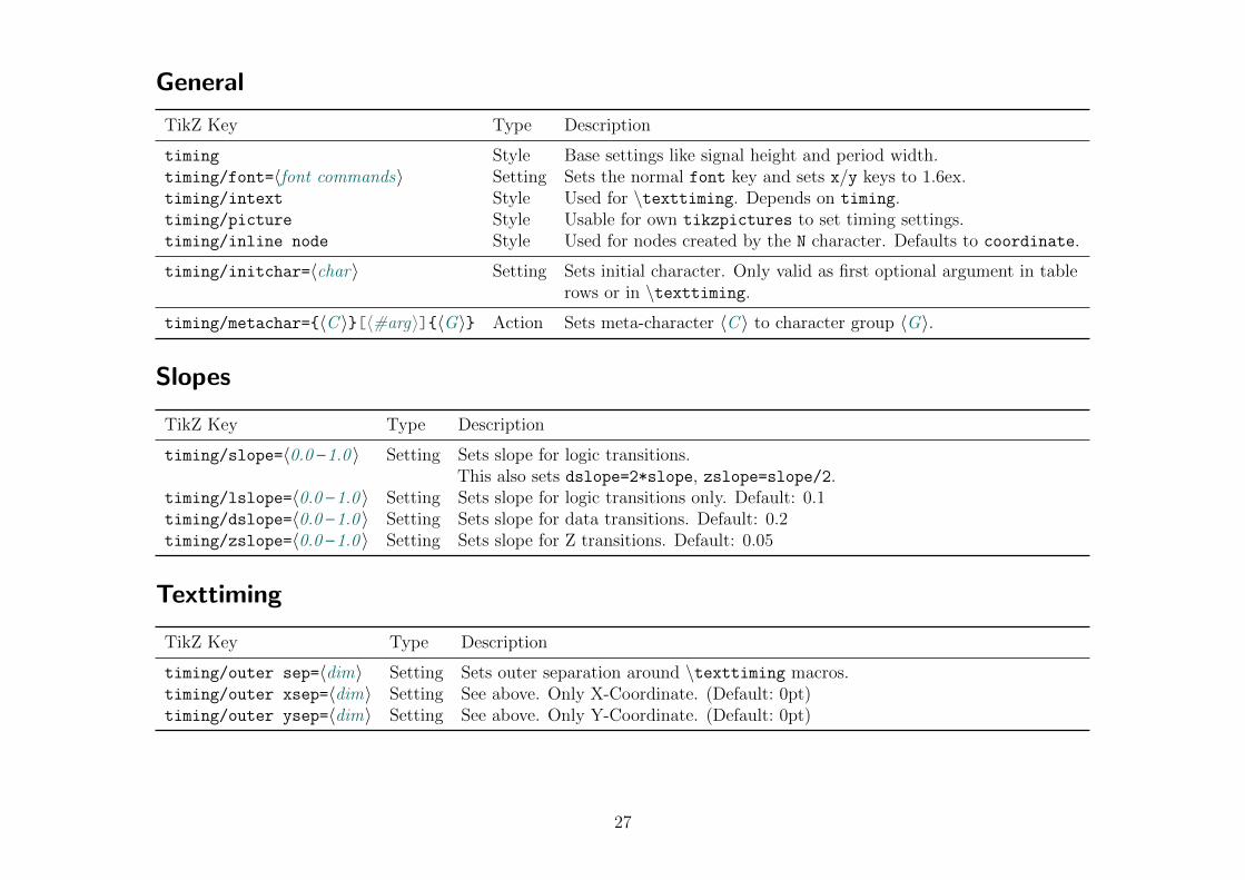
General
TikZ Key Type Description
timing Style Base settings like signal height and period width.timing/font=〈font commands〉 Setting Sets the normal font key and sets x/y keys to 1.6ex.timing/intext Style Used for \texttiming. Depends on timing.timing/picture Style Usable for own tikzpictures to set timing settings.timing/inline node Style Used for nodes created by the N character. Defaults to coordinate.
timing/initchar=〈char〉 Setting Sets initial character. Only valid as first optional argument in tablerows or in \texttiming.
timing/metachar={〈C 〉}[〈#arg〉]{〈G〉} Action Sets meta-character 〈C 〉 to character group 〈G〉.
Slopes
TikZ Key Type Description
timing/slope=〈0.0 – 1.0 〉 Setting Sets slope for logic transitions.This also sets dslope=2*slope, zslope=slope/2.
timing/lslope=〈0.0 – 1.0 〉 Setting Sets slope for logic transitions only. Default: 0.1timing/dslope=〈0.0 – 1.0 〉 Setting Sets slope for data transitions. Default: 0.2timing/zslope=〈0.0 – 1.0 〉 Setting Sets slope for Z transitions. Default: 0.05
Texttiming
TikZ Key Type Description
timing/outer sep=〈dim〉 Setting Sets outer separation around \texttiming macros.timing/outer xsep=〈dim〉 Setting See above. Only X-Coordinate. (Default: 0pt)timing/outer ysep=〈dim〉 Setting See above. Only Y-Coordinate. (Default: 0pt)
27

Grid
TikZ Key Type Description
timing/grid Style Style used for drawing grids. Depends on help lines and timing.timing/draw grid Action Enables background grids for \timing macros.timing/no grid Action Disabled background grids for \timing macros.
Table
TikZ Key Type Description
timing/table Style Used for tikztimingtable. Depends on timing.timing/table/grid Style Used for table grid. Depends on timing/grid.timing/table/lines Style Used for \horlines and \vertlines.timing/table/rules Style Used for \tablerules for top and bottom lines.timing/table/midrules Style Used for \tablerules between table head and body.timing/table/header Style Used for \tableheader.timing/table/title header Style Used for label header in \tableheader.timing/table/row header Style Used for timing row header in \tableheader.
timing/rowdist=〈distance〉 Setting Sets (baseline) distance between rows in a tikztimingtable. Default: 2(=2×signal height)
timing/coldist=〈distance〉 Setting Sets distance between columns in a tikztimingtable. Default: 1 (=1×periodwidth)
28
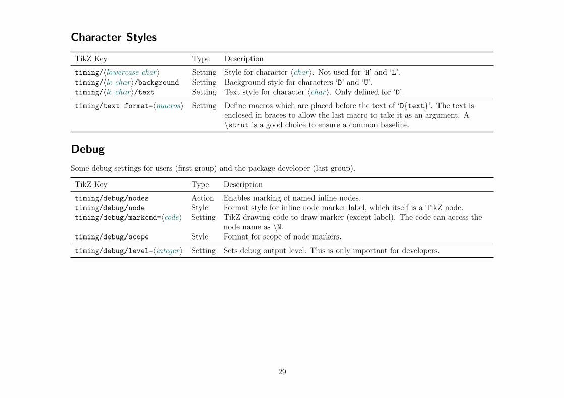
Character Styles
TikZ Key Type Description
timing/〈lowercase char〉 Setting Style for character 〈char〉. Not used for ‘H’ and ‘L’.timing/〈lc char〉/background Setting Background style for characters ‘D’ and ‘U’.timing/〈lc char〉/text Setting Text style for character 〈char〉. Only defined for ‘D’.
timing/text format=〈macros〉 Setting Define macros which are placed before the text of ‘D{text}’. The text isenclosed in braces to allow the last macro to take it as an argument. A\strut is a good choice to ensure a common baseline.
Debug
Some debug settings for users (first group) and the package developer (last group).
TikZ Key Type Description
timing/debug/nodes Action Enables marking of named inline nodes.timing/debug/node Style Format style for inline node marker label, which itself is a TikZ node.timing/debug/markcmd=〈code〉 Setting TikZ drawing code to draw marker (except label). The code can access the
node name as \N.timing/debug/scope Style Format for scope of node markers.
timing/debug/level=〈integer〉 Setting Sets debug output level. This is only important for developers.
29
4 Libraries for Further Characters
All default timing characters described in Table 2.1 are always made available by this package. Further, less-commoncharacters are provided by libraries which are loaded with the macro \usetikztiminglibrary{〈library〉}. This is done tohold the memory usage of this package small and reduce the risk of collisions with user-defined (meta-)characters. The fullsyntax for the above macro is \usetikztiminglibrary[〈options〉]{〈library,. . . 〉}[〈date〉], like the one for \usepackage.The date is used as a version number like for packages and is identical to the date of the tikztiming package.
30

4.1 arrows
Arrows The library ‘arrows’ enables two characters ‘A’ and ‘W’ which draw vertical up and down ArroW s. Such arrows areused in timing diagrams to mark special polarized events, like clock edges of another signal.
The width provided with these character is added as whitespace after the “zero-width” arrow: ‘A2AA’ results in ‘ ’.This space can be avoided by specifying the width to zero: ‘0A’. Like the ‘C’ and ‘T’ characters the subsequent arrow charactersare not combined into one.
The arrow tips can be changed using the TikZ styles for this characters. See section 3 for more information. The ‘A’ and ‘W’character should only be used which each each other, but not together with any other characters except with ‘S’ (space).
Table 4.1: Examples for Arrow Characters.
0A
AAA
3A
3{A}
3A 3A
3a 3a
AW AW
3{AW}
3{aw}
2S 2A 3W A W
Characters Resulting Diagram
31
4.2 either
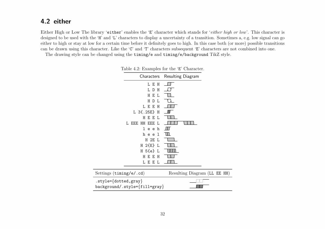
Either High or Low The library ‘either’ enables the ‘E’ character which stands for ‘either high or low ’. This character isdesigned to be used with the ‘H’ and ‘L’ characters to display a uncertainty of a transition. Sometimes a, e.g. low signal can goeither to high or stay at low for a certain time before it definitely goes to high. In this case both (or more) possible transitionscan be drawn using this character. Like the ‘C’ and ‘T’ characters subsequent ‘E’ characters are not combined into one.
The drawing style can be changed using the timing/e and timing/e/background TikZ style.
Table 4.2: Examples for the ‘E’ Character.
L E H
L D H
H E L
H D L
L E E H
L 3{.25E} H
H E E L
L EEE HH EEE L
l e e h
h e e l
H 2E L
H 2{E} L
H 5{e} L
H E E H
L E E L
Characters Resulting Diagram
Settings (timing/e/.cd) Resulting Diagram (LL EE HH)
.style={dotted,gray}background/.style={fill=gray}
32

4.3 overlays
Overlays The library ‘overlays’ enables the ‘O’ character which allows the overlaying of timing characters, i.e. differentgroups of timing characters are drawn on top of each other. This is not to be confused with ‘dynamic’ overlay provided bythe presentation class beamer. The tikz-timing library beamer provides some support for such overlays.
The ‘O’ character awaits a set of character enclosed by braces which are drawn as normal. The position before the ‘O’character is then restored and the following characters are drawn over them. Older versions of this character awaited a secondset of characters in braces but this braces are now optional. The exact syntax is:
〈chars before〉 O{〈background chars〉} {〈foreground chars〉} 〈chars after〉or, without second set of braces, but equal:
〈chars before〉 O{〈background chars〉} 〈foreground chars, . . . 〉It is the responsibility of the user to make sure that the lines drawn by the first set reconnect to the main lines or do
something else useful. The modifier ‘;’ can be used to restart the drawn line, e.g. to change to a different color. This is notdone automatically to give the user the freedom if and where this should happen. It is recommended to start and end the setwith characters identical with the main line to avoid ugly connection points.
Please note that the width of the first argument is ignored and does not count to the total width of the diagram line. Thecharacters following the overlay should therefore be as wide or wider as the one of the overlay, otherwise the bounding boxand background grid will be incorrect.
Overlays can be cascaded , i.e. an overlay can be included in the first argument of another overlay. New in v0.7
Table 4.3: Examples for the ‘O’ Overlay Character.
LLL O{HH}{LL} HHH
LLL O{HHH}{LL} HHH
LLL O{;[gray]HH.1H;}{LLH} HH
LL O{L;[gray]HH.1H;}{LLLH} HH
DD{} O{zd}{D}d 2D
ZZ O{Z D Z}{Z 1.1M .9Z} ZZ
ZZ O{d Z}O{DZ}{dD} ZZ
Characters Resulting Diagram
ZZ O{dDZ}O{DZ}{dZ} ZZ
ZZ 3D O{dDZ}{DZ} ZZ
ZZ 3D O{dDZ}O{DZ}{dZ} ZZ
ZZ 3D O{3D} DZZ
Z O{DD} ZDDD O{DDZZ} DZ 2S
Z O{6D Z}{Z 4D Z} Z
Z O{8D Z}O{Z 6D Z}{2Z 4D 2Z} Z
Characters Resulting Diagram
33

4.4 clockarrows
Clock Arrows The library ‘clockarrows’ is changing the ‘C’ clock character to contain arrows which mark the rising and/or New in v0.7
falling clock edge. By default the rising edges are marked. To simplify the implementation only the transition from a ‘C’ toanother ‘C’ character contains the arrows but not transitions from or to different characters, like ‘HCH’ or ‘LCL’.
The arrows can be controlled using the TikZ styles shown in Table 4.4 below. This styles can also be used as libraryoptions. The key “directory” ‘timing/c’ must be dropped for options, e.g.
\usetikztiminglibrary[rising arrows]{clockarrows}.
Table 4.4: TikZ Styles for Clock Arrows.
TikZ Style Description
timing/c/rising arrows Mark (only) rising edges with arrows.timing/c/falling arrows Mark (only) falling edges with arrows.timing/c/dual arrows Mark both rising and falling edges with arrows.timing/c/no arrows Do not mark any edges with arrows. (Default)
timing/c/arrow Style for arrows. Can be modified to change arrow tip etc. (Default: {})timing/c/arrow pos=〈0.--1.〉 Position of arrows, i.e. its tip, on the edge. May needs adjustment if different arrow tip
shapes are selected. (Default: 0.95)timing/c/arrow tip=〈name〉 Tip shape of arrows. See the PGF manual for the list of arrow tips. (Default: ‘to’)
Table 4.5: Examples for the Clock Arrows.
Settings (timing/c/.cd) Resulting Diagram (11{C})
rising arrows
falling arrows
no arrows
dual arrows
Settings (timing/c/.cd) Resulting Diagram (11{C})
arrow pos=.7
arrow pos=.4
arrow tip=latex
arrow tip=stealth
34
4.5 columntype
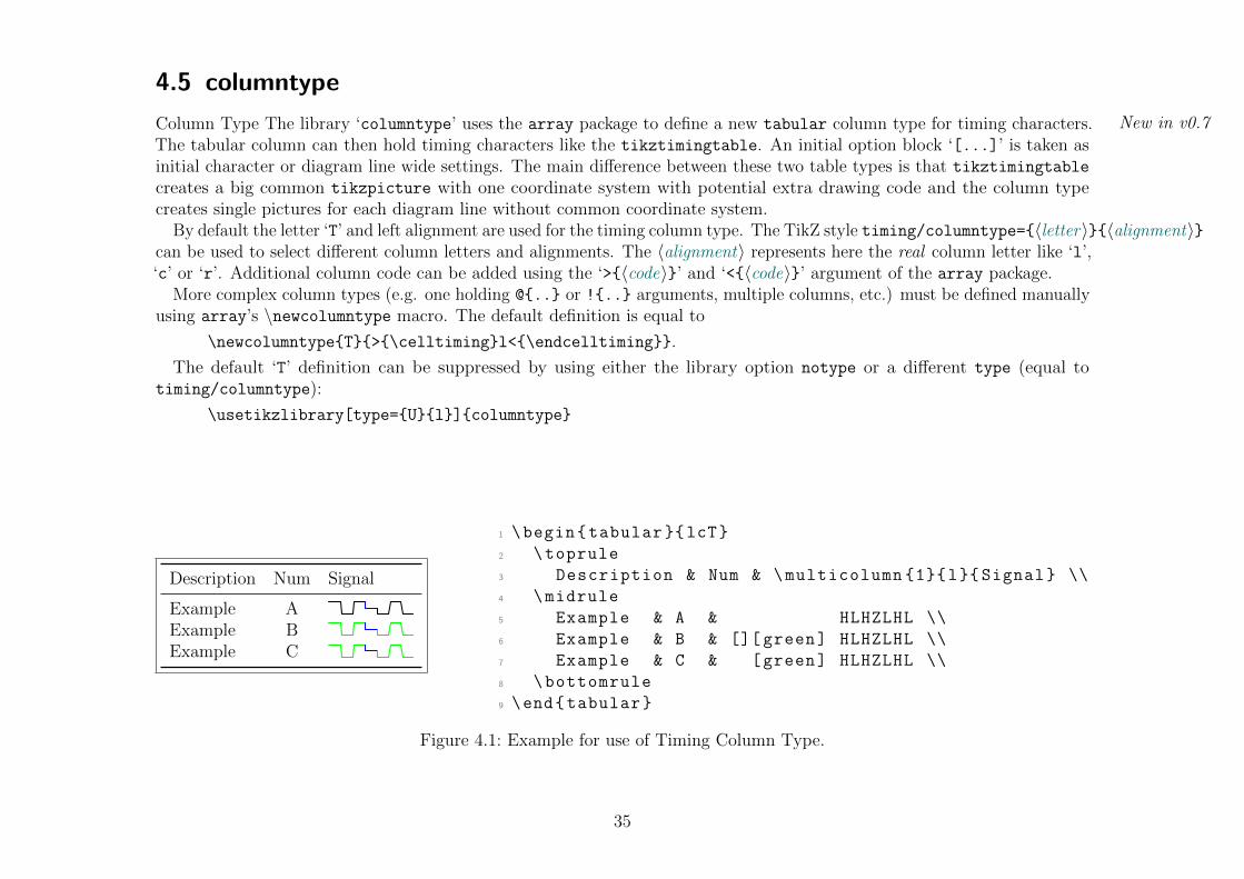
Column Type The library ‘columntype’ uses the array package to define a new tabular column type for timing characters. New in v0.7
The tabular column can then hold timing characters like the tikztimingtable. An initial option block ‘[...]’ is taken asinitial character or diagram line wide settings. The main difference between these two table types is that tikztimingtablecreates a big common tikzpicture with one coordinate system with potential extra drawing code and the column typecreates single pictures for each diagram line without common coordinate system.
By default the letter ‘T’ and left alignment are used for the timing column type. The TikZ style timing/columntype={〈letter〉}{〈alignment〉}can be used to select different column letters and alignments. The 〈alignment〉 represents here the real column letter like ‘l’,‘c’ or ‘r’. Additional column code can be added using the ‘>{〈code〉}’ and ‘<{〈code〉}’ argument of the array package.
More complex column types (e.g. one holding @{..} or !{..} arguments, multiple columns, etc.) must be defined manuallyusing array’s \newcolumntype macro. The default definition is equal to
\newcolumntype{T}{>{\celltiming}l<{\endcelltiming}}.
The default ‘T’ definition can be suppressed by using either the library option notype or a different type (equal totiming/columntype):
\usetikzlibrary[type={U}{l}]{columntype}
Description Num Signal
Example AExample BExample C
1 \begin{tabular }{lcT}
2 \toprule
3 Description & Num & \multicolumn {1}{l}{ Signal} \\
4 \midrule
5 Example & A & HLHZLHL \\
6 Example & B & [][ green] HLHZLHL \\
7 Example & C & [green] HLHZLHL \\
8 \bottomrule
9 \end{tabular}
Figure 4.1: Example for use of Timing Column Type.
35

4.6 nicetabs
Nice Timing Tables The library ‘nicetabs’ uses the settings of the array and booktabs packages to improve the layout of New in v0.7
tikztimingtables. The resulting table matches a tabular{rT} table which uses the above packages and the columntype
library. The table macros \tabcolsep, \arraystretch and \extrarowheight are obeyed.The original table layout is designed to produce integer coordinates between the rows to simplify the drawing of extra
drawings (see \extracode). The improved layout will cause non-integer coordinates, but in-line nodes and the \rowdist and\coldist macros can be used to draw extra material relatively to the rows.
The TikZ styles ‘timing/nice tabs’ (default) and ‘timing/no nice tabs’ can be used to activate and deactivate thelayout, e.g. for each table. Both settings can be given as a library option, but without the ‘timing/’ path.
Table 4.6: Timing tables using ‘nice’ (left) and normal (right) Layout. For comparison a {tabular}{rT} table is placed ingrey below the left table.
Name Timing
ExampleExampleExample
ExampleExampleExample
Name Timing
Example
Example
Example
Name Timing
36

4.7 counters
Counter Character The library ‘counters’ allows the easy definition of meta-characters which implement up-counters. These New in v0.7
Extended inv0.7a
characters show the counter value using the ‘D{}’ character and increment it by one every time they are used. A secondcharacter can be defined to (re-)set the counter to a specific value. The counter values can be decimal (base-10, default),hexadecimal (base-16) or any other base from 2 to 36. By default the lower case version of the counter character is defined toproduce the same output only with half the width.
Counter characters are defined using the TikZ key ‘timing/counter/new={char=〈char〉,〈settings〉}’ which can also bewritten as ‘timing/new counter’. The 〈settings〉 are TikZ keys themselves and are shown by Table 4.7. One or more ‘new’keys (path ‘timing/counter’ removed) can be given as library options. The counter values are global like normal LATEXcounters. They should be reset in every timing diagram line before they are used.
Counter Style
The styles ‘timing/counter/〈char〉’ and ‘timing/counter/〈char〉/text’ (both initially empty) are used to format thegraphic and text style of this counter, respectively. Because the ‘D{}’ character is used internally the above styles need tochange the corresponding ‘D’ styles. This changes are only local and do not affect further ‘real’ ‘D’ characters.
The settings ‘fg style’, ‘bg style’ and ‘text style’ can be used to quickly define the foreground (i.e. line), backgroundand text style of the counter. While the ‘text style’ setting simple sets the ‘timing/counter/〈char〉/text’ style, the othertwo are a shortcut for
\tikzset{timing/counter/〈char〉/.style={%timing/d/.style={〈fg style〉},timing/d/background/.style={〈bg style〉},
}}
Additional Macros
\tikztimingcounter{〈char〉}\tikztimingsetcounter{〈char〉}{〈pgfmath expression〉}
The value of counter 〈char〉 can be read or set using this macros.
37

Table 4.7: Settings for Counter Meta-Characters
Key name Description
char=〈char〉 Defines the given 〈char〉 to be a counter meta-character. If it is a upper casecharacter the lower case character will produce the same output but with the halfwidth, as long this is not overwritten with the half with char key.
half width char=〈char〉 Defines the given 〈char〉 to be the half width version of the counter value. Bydefault this is the lower case version of the counter character given with char. Anempty value for 〈char〉 deactivates the definition of a half width character.
reset char=〈char〉 Defines the given 〈char〉 to (re-)set the counter value to the ‘width’ of the character,i.e. the number preceding it. The lower case version of the reset 〈char〉 is notdefined.
reset type=〈width—arg—both—Both〉 Defines the type of the reset character, i.e. how the reset value is obtained.width Width is reset value: ‘〈value〉〈char〉’, e.g. ‘0R’. Value can not be negative.arg Reset value is provided as argument: ‘〈char〉{〈value〉}’, e.g. ‘R{-1}’.both Uppercase 〈char〉 is width-type, lowercase 〈char〉 is arg-type reset char.Both Lowercase 〈char〉 is width-type, uppercase 〈char〉 is arg-type reset char.
base=〈Num 2-36 〉 Defines the numeric base of the counter. If not used the base 10 is used.
increment=〈pgfmath expression〉 Sets the increment which is added every time the counter character is used. Thiscan be a formula which result is truncated to a integer. The current counter valuecan be referenced as \N. The increment can be negative which causes the counterto count down. Default: 1
max value=〈pgfmath expression〉 Sets the maximum counter value. Default: not setmin value=〈pgfmath expression〉 Sets the minimum counter value. Default: not setwraps=〈true—false〉 If set to true the counter wraps around, i.e. it counts to the minimum value
when counting over the maximum value or the other way around if increment isnegative. Initial value: false. Default value: true
bg style=〈TikZ style(s)〉 Sets the background style of the counter.fg style=〈TikZ style(s)〉 Sets the foreground (line etc.) style of the counter.text style=〈TikZ style(s)〉 Sets the text style of the counter.text format=〈TEXcode〉 Sets the format code of the counter value. This should be a macro which receives
the counter value as first argument.
38

Examples:
Counter character ‘Q’ with base 16 (hexadecimal). ‘R’ resets the counter. The counter value should be in blue text typer font.\tikzset{timing/new counter={char=Q,base=16,reset char=R}}
\tikzset{timing/counter/Q/text/.style={font=\ttfamily,blue}}
\texttiming{ 3Q 3{Q} R 12{Q} 2R Q qq 0R 3{Q} }
gives: 0 1 2 3 1 2 3 4 5 6 7 8 9 A B C 2 34 0 1 2
Dec 0 1 2 3 4 5 6 7 8 9 10 11 12 13 14 15 0 1 2 3 4 5 6 7 8 9 10 11 12 13 14 15 0
Bin 0000 0001 0010 0011 0100 0101 0110 0111 1000 1001 1010 1011 1100 1101 1110 1111 0000 0001 0010 0011 0100 0101 0110 0111 1000 1001 1010 1011 1100 1101 1110 1111 0000
Oct 000 001 002 003 004 005 006 007 010 011 012 013 014 015 016 017 000 001 002 003 004 005 006 007 010 011 012 013 014 015 016 017 000
Hex 0 1 2 3 4 5 6 7 8 9 A B C D E F 0 1 2 3 4 5 6 7 8 9 A B C D E F 0
1 \scalebox {2}{%
2 \begin{tikztimingtable}
3 Dec & [timing/counter/new={char=Q,max value=15, wraps ,text style ={font=\ scriptsize }}] 33{Q}d\\
4 Bin & [timing/counter/new={char=Q,max value=15,base=2, digits=4,wraps ,text style={font=\tiny ,scale =.8}}] 33{Q}d\\
5 Oct & [timing/counter/new={char=Q,max value=15,base=8, digits=3,wraps ,text style={font=\tiny }}] 33{Q}d\\
6 Hex & [timing/counter/new={char=Q,max value=15,base=16, wraps ,text style={font=\ scriptsize }}] 33{Q}d\\
7 \extracode
8 \begin{background }[shift ={(0.1 ,0)} , help lines]
9 \vertlines {}
10 \end{background}
11 \end{tikztimingtable}
12 }%
39

4.8 advnodes
Advanced Nodes The library ‘advnodes’ changes the in-line nodes, i.e. the ‘N’ character, to provide multiple transition New in v0.7
dependent and independent node anchors shown in Table 4.8.Most transitions provide the three logic level anchors ‘low’, ‘mid’ and ‘high’ which lie on the drawn timing line. Transitions
of ‘double line’ characters like ‘D’ can have two low and/or high level anchors which are called ‘low2’ and ‘high2’.To align marker lines over multiple rows inside a tikztimingtable a set of transition independent node anchors are
provided: ‘LOW’, ‘MID’, ‘HIGH’. This anchors lie all at the begin of the transition at the appropriate logic levels. With thenormal coordinate-like in-line nodes the vertical node (center) position has to be taken into account, while this advancedanchors do this automatically.
Often marker lines should start and end with a little vertical offset from the timing diagram to be more distinguishable.For this the two anchors ‘TOP’ and ‘BOTTOM’ exist. They lie above and below of ‘HIGH’ and ‘LOW’, respectively. The verticaldistance can be set using ‘timing/nodes/offset=〈dim. or number〉’.Please note that the node center of advanced nodes will be different for some transitions. The ‘center’ anchor (used by
default if no node anchor is provided) will be placed at the logical center of the transition, i.e. mostly in the middle of it. Inorder not to break existing diagrams which use nodes as references to draw additional material an TikZ styles is providedto select between the old and new node centers. This styles can be used globally or locally as required. The two explicitanchors ‘new center’ and ‘old center’ are also provided. For existing documents with diagrams using normal nodes it isrecommended to switch to simple nodes or to the old node centers globally or select such a style for each old diagram.
The following TikZ settings can be used with the library. The node style settings affect all new nodes after them. Thecenter settings affect all following references (e.g. ‘(NodeName)’ or ‘(NodeName.center)’) of advanced nodes. The settingscan be used as library options with the ‘timing/nodes/’ part removed.
TikZ Setting Description
timing/nodes/advanced Selects advanced in-line nodes. (library default)timing/nodes/simple Selects simple coordinate-style in-line nodes. (package default)
timing/nodes/new center Center of in-line nodes is in the new position. (default for advanced)timing/nodes/old center Center of in-line nodes is in the old position. (always on for simple)
timing/nodes/offset Sets offset for TOP and BOTTOM anchors. Can be a dimension with unit or a factor to thecurrent y unit. (default: 0.25)
40

Examples:
‘\usetikztiminglibrary[simple]{advnodes}’ loads the library with nodes default to the old ‘simple’ style.‘\usetikztiminglibrary[old center]{advnodes}’ loads the library with advanced nodes with have the center at thesame place as the normal simple nodes. This is a good “compatibility mode” for existing pre-v0.7 diagrams.‘\begin{tikztimingtable}[timing/nodes/simple]’ starts a timing table which uses simple nodes.‘\begin{tikztimingtable}[timing/nodes/.cd,advanced,old center]’starts a timing table which uses advanced nodes with old node centers.
41

Table 4.8: Transition Dependent Anchor Points of Advanced Nodes
tofrom L H X D E
L
H
X
D
D{A} A A A A A A
E
0LE
0HE
Legend: low mid highlow2 high2LOW MID HIGHnew center old center
42

4.9 ifsym
Compatibility Macros for ifsym package The library ‘ifsym’ provides macros and timing styles to emulate the behaviour of New in v0.7
the ifsym package when loaded with the electronic option. The ifsym package was an early inspiration to this packageand this library allows the usage of ifsym style timing symbol macros and characters (‘\textifsym{〈characters〉}’ whichuses ‘\texttiming[timing/ifsym]{〈characters〉}’) which are described in Table 4.9 and Table 4.10, respectively. This isuseful if old ifsym timing diagrams should be reused. The tikz-timing replacements are a very close match and do not needa special font to be installed. The graphic quality should be equal or better than the original. The intermixing of ifsym andtikz-timing style characters in a \textifsym macro (the one provided by this library, not the one from the ifsym package)is supported but it is not guaranteed to work 100% properly. Please note that the ‘M’ character is defined to use ‘X’ in black.
The library can be loaded with one of the options ‘provide’ (default), ‘new’, ‘renew’ or ‘off’, respectively. These select ifthe macros should be defined using \providecommand, \newcommand, \renewcommand or not at all. This can be useful if theifsym package is loaded beforehand.
Table 4.9: ifsym style Timing Symbol Macros
Macro Symbol Description (trivial)
\RaisingEdge Raising Edge\FallingEdge Falling Edge\ShortPulseHigh Short Pulse High\ShortPulseLow Short Pulse Low\PulseHigh Normal Pulse High\PulseLow Normal Pulse Low\LongPulseHigh Long Pulse High\LongPulseLow Long Pulse Low
Table 4.10: ifsym style Timing Characters (from ifsym manual)
Character Symbol Description
l, h , Short low or high level signal.
L, H , Long low or high level signal.
| Transition/glitch between L/H or H/L levels.
m, d , Short middle or double level signal.
M, D , Long middle or double level signal.
<, << , Short or long slope between middle and double level.
>, >> , Short or long slope between double and middle level.
43
4.10 interval
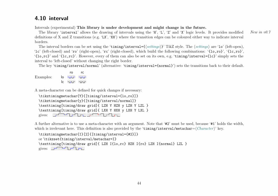
Intervals (experimental) This library is under development and might change in the future.The library ‘interval’ allows the drawing of intervals using the ‘H’, ‘L’, ‘Z’ and ‘X’ logic levels. It provides modified New in v0.7
definitions of X and Z transitions (e.g. ‘LX’, ‘XH’) where the transition edges can be coloured either way to indicate intervalborders.
The interval borders can be set using the ‘timing/interval={〈settings〉}’ TikZ style. The 〈settings〉 are ‘lo’ (left-open),‘lc’ (left-closed) and ‘ro’ (right-open), ‘rc’ (right-closed), which build the following combinations: ‘{lo,ro}’, ‘{lc,ro}’,‘{lo,rc}’ and ‘{lc,rc}’. However, every of them can also be set on its own, e.g. ‘timing/interval={lc}’ simply sets theinterval to ‘left-closed’ without changing the right border.
The key ‘timing/interval/normal’ (alternative: ‘timing/interval={normal}’) sets the transitions back to their default.
Examples:ro rc
lolc
A meta-character can be defined for quick changes if necessary:
\tikztimingmetachar{Y}{[timing/interval={lo,ro}]}
\tikztimingmetachar{y}{[timing/interval/normal]}
\texttiming[timing/draw grid]{ LZH Y HZH y LZH Y LZL }
\texttiming[timing/draw grid]{ LXH Y HXH y LXH Y LXL }
gives:
A further alternative is to use a meta-character with an argument. Note that ‘#2’ must be used, because ‘#1’ holds the width,which is irrelevant here. This definition is also provided by the ‘timing/interval/metachar=〈Character〉’ key.
\tikztimingmetachar{I}[2]{[timing/interval={#2}]}
or \tikzset{timing/interval/metachar=I}\texttiming[timing/draw grid]{ LZH I{lo,rc} HZH I{ro} LZH I{normal} LZL }
gives:
44
4.11 beamer
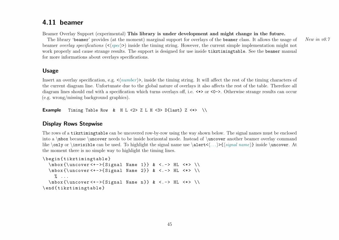
Beamer Overlay Support (experimental) This library is under development and might change in the future.The library ‘beamer’ provides (at the moment) marginal support for overlays of the beamer class. It allows the usage of New in v0.7
beamer overlay specifications (<〈spec〉>) inside the timing string. However, the current simple implementation might notwork properly and cause strange results. The support is designed for use inside tikztimingtable. See the beamer manualfor more informations about overlays specifications.
Usage
Insert an overlay specification, e.g. <〈number〉>, inside the timing string. It will affect the rest of the timing characters ofthe current diagram line. Unfortunate due to the global nature of overlays it also affects the rest of the table. Therefore alldiagram lines should end with a specification which turns overlays off, i.e. <*> or <0->. Otherwise strange results can occur(e.g. wrong/missing background graphics).
Example Timing Table Row & H L <2> Z L H <3> D{last} Z <*> \\
Display Rows Stepwise
The rows of a tikztimingtable can be uncovered row-by-row using the way shown below. The signal names must be enclosedinto a \mbox because \uncover needs to be inside horizontal mode. Instead of \uncover another beamer overlay commandlike \only or \invisible can be used. To highlight the signal name use \alert<〈. . . 〉>{〈signal name〉} inside \uncover. Atthe moment there is no simple way to highlight the timing lines.
\begin{tikztimingtable}
\mbox{\uncover <+->{Signal Name 1}} & <.-> HL <*> \\
\mbox{\uncover <+->{Signal Name 2}} & <.-> HL <*> \\
% ...
\mbox{\uncover <+->{Signal Name n}} & <.-> HL <*> \\
\end{tikztimingtable}
45

Display Columns Stepwise
Different sections (‘columns’) of timing diagrams in a tikztimingtable can be uncovered stepwise using the way shownbelow. In this example the second section/column will be uncovered in the second slide. The first is always visible. Furthersections/columns can be uncovered in further slides.
Please note that the total width of the table is constant and e.g. \tablerules will always cover the full width independentof overlays.
\begin{tikztimingtable}
Signal Name 1 & 10D{Sec. 1} <2> 10D{Sec. 2} <*> \\
Signal Name 2 & 10D{Sec. 1} <2> 10D{Sec. 2} <*> \\
% ...
Signal Name n & 10D{Sec. 1} <2> 10D{Sec. 2} <*> \\
\end{tikztimingtable}
Overlay Extra Code
The beamer overlay specifications can be used inside the \extracode section like in a normal tikzpicture environment.However, in both cases strange results will occur if the end of the environment is hidden by an overlay specification. Due tothis reason it is recommended to only use overlay commands which affect only an argument, like \only<〈. . . 〉>{〈code〉}, or toplace a plain \onlayer before the end of the environment.
\begin{tikztimingtable}
Signal Name 1 & 10D{Sec. 1} <2> 10D{Sec. 2} <*> \\
% ...
\extracode
% either
\draw <2> (0,0) -- (2,0); \only <3> { ... }
% or
\onlayer <2>
% and then at the very end:
\onlayer % or \onlayer <*>
\end{tikztimingtable}
46
5 Examples
This section shows some examples by putting either the full source code or only the needed characters beside the graphicalresult. Please note that the displayed syntax is the one of \timing where the initial character is declared as optional argument([〈char〉]) inside/together with the logic characters. The syntax of \textttiming is identical except the initial characteris given as a normal optional argument before the characters argument. All examples except Example 1 are attached incompilable form to this PDF.
47
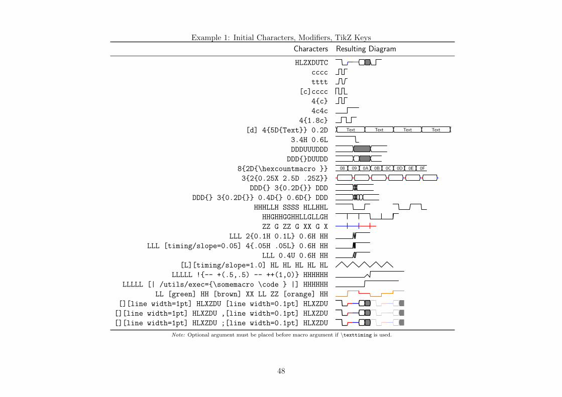
Example 1: Initial Characters, Modifiers, TikZ Keys
HLZXDUTC
cccc
tttt
[c]cccc
4{c}
4c4c
4{1.8c}
[d] 4{5D{Text}} 0.2D Text Text Text Text
3.4H 0.6L
DDDUUUDDD
DDD{}DUUDD
8{2D{\hexcountmacro }} 08 09 0A 0B 0C 0D 0E 0F
3{2{0.25X 2.5D .25Z}}
DDD{} 3{0.2D{}} DDD
DDD{} 3{0.2D{}} 0.4D{} 0.6D{} DDD
HHHLLH SSSS HLLHHL
HHGHHGGHHLLGLLGH
ZZ G ZZ G XX G X
LLL 2{0.1H 0.1L} 0.6H HH
LLL [timing/slope=0.05] 4{.05H .05L} 0.6H HH
LLL 0.4U 0.6H HH
[L][timing/slope=1.0] HL HL HL HL HL
LLLLL !{-- +(.5,.5) -- ++(1,0)} HHHHHH
LLLLL [| /utils/exec={\somemacro \code } |] HHHHHH
LL [green] HH [brown] XX LL ZZ [orange] HH
[][line width=1pt] HLXZDU [line width=0.1pt] HLXZDU
[][line width=1pt] HLXZDU ,[line width=0.1pt] HLXZDU
[][line width=1pt] HLXZDU ;[line width=0.1pt] HLXZDU
Characters Resulting Diagram
Note: Optional argument must be placed before macro argument if \texttiming is used.
48
Name
Clock
Signal Text
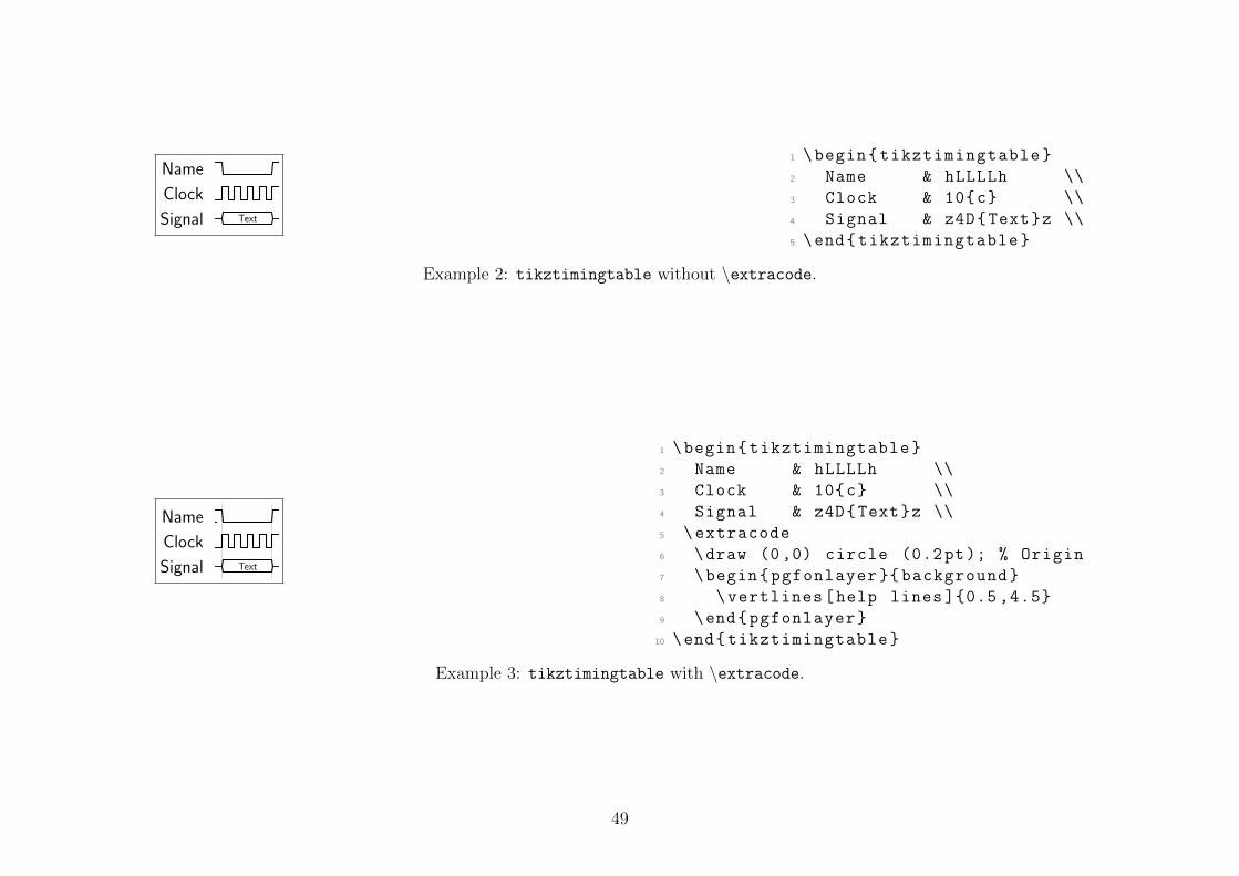
1 \begin{tikztimingtable}
2 Name & hLLLLh \\
3 Clock & 10{c} \\
4 Signal & z4D{Text}z \\
5 \end{tikztimingtable}
Example 2: tikztimingtable without \extracode.
Name
Clock
Signal Text
1 \begin{tikztimingtable}
2 Name & hLLLLh \\
3 Clock & 10{c} \\
4 Signal & z4D{Text}z \\
5 \extracode
6 \draw (0,0) circle (0.2pt); % Origin
7 \begin{pgfonlayer }{ background}
8 \vertlines[help lines ]{0.5 ,4.5}
9 \end{pgfonlayer}
10 \end{tikztimingtable}
Example 3: tikztimingtable with \extracode.
49

1 \begin{tikzpicture }[x=4cm ,y=4cm]
2 \draw (0,0) rectangle (1,1);
3 \draw (0.2 ,0.7) circle (10pt);
4 \begin{scope}[green]
5 \draw (0.1 ,0.1) -- +(0.8 ,0.2);
6 \timing at (0.3 ,0.4) {hlzhhlhhl };
7 \end{scope}
8 \timing [rotate =-30]
9 at (0.4 ,0.7) {HLZHHLHHL };
10 \end{tikzpicture}
Example 4: \timing inside general tikzpicture.
1 \Huge
2 \begin{tikzpicture }[ timing/picture ,thick ,
3 timing/nodes/advanced]
4 \timing at (0,2) {hH N(A) LHLHL};
5 \timing[timing/slope =.25] at (0,0)
6 {HLL N(B) HHLl};
7 \draw [orange ,semithick]
8 (A.mid) ellipse (.2 and .6)
9 (B.mid) ellipse (.2 and .6);
10 \draw [orange ,semithick ,->]
11 ($ (A.mid) - (0 ,.6) $)
12 parabola [bend pos =0.5]
13 ($ (B.mid) + (0 ,.6) $);
14 \end{tikzpicture}
Example 5: Using In-Line Nodes to draw Relationships.
50
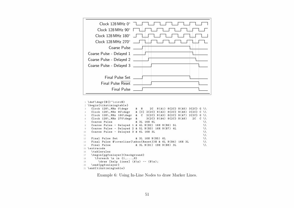
Clock 128 MHz 0◦
Clock 128 MHz 90◦
Clock 128 MHz 180◦
Clock 128 MHz 270◦
Coarse Pulse
Coarse Pulse - Delayed 1
Coarse Pulse - Delayed 2
Coarse Pulse - Delayed 3
Final Pulse Set
Final Pulse Reset
Final Pulse
1 \def\degr{${}^\ circ$}
2 \begin{tikztimingtable}
3 Clock 128\,MHz 0\degr & H 2C N(A1) 8{2C} N(A5) 3{2C} G \\
4 Clock 128\,MHz 90\ degr & [C] 2{2C} N(A2) 8{2C} N(A6) 2{2C} C \\
5 Clock 128\,MHz 180\ degr & C 2{2C} N(A3) 8{2C} N(A7) 2{2C} G \\
6 Clock 128\,MHz 270\ degr & 3{2C} N(A4) 8{2C} N(A8) 2C C \\
7 Coarse Pulse & 3L 16H 6L \\
8 Coarse Pulse - Delayed 1 & 4L N(B2) 16H N(B6) 5L \\
9 Coarse Pulse - Delayed 2 & 5L N(B3) 16H N(B7) 4L \\
10 Coarse Pulse - Delayed 3 & 6L 16H 3L \\
11 \\
12 Final Pulse Set & 3L 16H N(B5) 6L \\
13 Final Pulse $\overline {\mbox{Reset}}$ & 6L N(B4) 16H 3L \\
14 Final Pulse & 3L N(B1) 19H N(B8) 3L \\
15 \extracode
16 \tablerules
17 \begin{pgfonlayer }{ background}
18 \foreach \n in {1 ,...,8}
19 \draw [help lines] (A\n) -- (B\n);
20 \end{pgfonlayer}
21 \end{tikztimingtable}
Example 6: Using In-Line Nodes to draw Marker Lines.
51

Clock 90◦
Clock 180◦
Clock 270◦
Clock 0◦
Start of Tsw
Input Pulse
Set 3
Set 2
Set 1
Set 0
Reset
Final Pulse
Counter Full 0 1 2 DM DM+1
DM = MSBs of Duty Cycle
1 \def\degr #1{\ makebox [2em][r]{#1}\ ensuremath {{}^{\ circ }}}%
2
3 \begin{tikztimingtable }[%
4 timing/dslope =0.1, timing /. style={x=2ex ,y=2ex}, x=2ex,
5 timing/rowdist =3ex,
6 timing/name/.style ={font=\ sffamily\scriptsize},
7 timing/nodes/advanced ,
8 ]
9 Clock \degr {90} & l 2{C} N(A1) 5{C} \\
10 Clock \degr {180}& C 2{C} N(A2) 4{C} c\\
11 Clock \degr {270}& h 3{C} N(A3) 4{C} \\
12 Clock \degr {0} & [C] 2{C} N(A0) 2{C} N(A4) 3{C}c ;[ dotted]
13 2L; 2{C} N(A5) 3{C} \\
14 Start of T$_{\text{sw}}$ & 4S G N(start) \\
15 Input Pulse & 2.0L 2H 3.5L ;[ dotted] 2L; 5L \\
16 Set 3 & 2.5L 2H 3.0L ;[ dotted] 2L; 5L \\
17 Set 2 & 3.0L 2H 2.5L ;[ dotted] 2L; 5L \\
18 Set 1 & 3.5L 2H 2.0L ;[ dotted] 2L; 5L \\
19 Set 0 & 4.0L 2H 1.5L ;[ dotted] 2L; 5L \\
20 Reset & 7.5L ;[ dotted] 2L; 2L N(reset) 2H 1L \\
21 Final Pulse & 2.5L N(B1) e N(B2) e N(B3) e 3.5H; [dotted]
22 2H; 2H 3L \\
23 Counter & N(x) 2D{Full} N(B0) 2D{0} N(B4) 2D{1} 1.5D;[ dotted]
24 .25D{2} 1.75D{};
25 2D{~D$_\text{M}$} N(B5) 2D{D$_\text{M}$+1} D N(y)\\
26 \extracode
27 %\ tablegrid
28 \node[anchor=north] at ($ (x) ! .5 ! (y) - (0 ,.75) $)
29 {\ scriptsize D$_\text{M}$ = MSBs of Duty Cycle};
30 \begin{background }[ timing/picture ,line width =.06ex,color=black !60]
31 \foreach \n in {0 ,...,5}
32 \draw (A\n.TOP) -- (B\n.BOTTOM );
33 \end{background}
34 \end{tikztimingtable }%
Example 7: Adjusting Diagram Parameters and using Advanced In-Line Nodes to draw Marker Lines.
52

clocked
positive edge triggered
clock
S
R
Q
Q
Q
Q
1 \definecolor{bgblue }{rgb }{0.41961 ,0.80784 ,0.80784}%
2 \definecolor{bgred }{rgb }{1 ,0.61569 ,0.61569}%
3 \definecolor{fgblue }{rgb }{0 ,0 ,0.6}%
4 \definecolor{fgred }{rgb }{0.6 ,0 ,0}%
5 \begin{tikztimingtable }[ timing/slope=0,
6 timing/coldist =2pt,xscale =2.05, yscale =1.1, semithick]
7 \scriptsize clock & 7{C}\\
8 S & .75L h 2.25L H LLl [fgblue ]\\
9 R & 1.8L .8H 2.2L 1.4H 0.8L [fgblue ]\\
10 Q & L .8H 1.7L 1.5H LL\\
11 $\overline {\mbox{Q}}$ & H .8L 1.7H 1.5L HH\\
12 Q & LHHHHLL[fgred ]\\
13 $\overline {\mbox{Q}}$ & HLLLLHH[fgred ]\\
14 \extracode
15 \makeatletter
16 \begin{pgfonlayer }{ background}
17 \shade [right color=bgblue ,left color=white]
18 (7, -8.45) rectangle (-1,-4.6);
19 \shade [right color=bgred ,left color=white]
20 (7, -12.8) rectangle (-1,-8.6);
21 \begin{scope }[gray ,semitransparent ,semithick]
22 \horlines {}
23 \foreach \x in {1 ,...,6}
24 \draw (\x,1) -- (\x, -12.8);
25 % similar: \vertlines {1 ,...,6}
26 \end{scope}
27 \node [anchor=south east ,inner sep=0pt]
28 at (7, -8.45) {\tiny clocked };
29 \node [anchor=south east ,inner sep=0pt,fgred]
30 at (7, -12.8) {\tiny positive edge triggered };
31 \end{pgfonlayer}
32 \end{tikztimingtable }%
Example 8: SR flip-flop timing diagram (left top). Redrawn from image (left bottom)http://commons.wikimedia.org/wiki/File:SR_FF_timing_diagram.png
53

CPOL=0
CPOL=1
Cycle # 1 2 3 4 5 6 7 8
MISO z 1 2 3 4 5 6 7 8 z
MOSI z 1 2 3 4 5 6 7 8 z
Cycle # 1 2 3 4 5 6 7 8
MISO z 1 2 3 4 5 6 7 8 z
MOSI z 1 2 3 4 5 6 7 8 z
SCK
SS
CPHA=0
CPHA=1
1 \begin{tikztimingtable }[
2 timing/d/background /.style={fill=white},
3 timing/lslope =0.2,
4 timing/counter/new={char=Q,reset char=R},
5 ]
6 CPOL=0 & LL 15{T} LL \\
7 CPOL=1 & HH 15{T} HH \\
8 & H 17L H \\
9 \\
10 Cycle \# & U R 8{2Q} 2U \\
11 MISO & D{z} R 8{2Q} 2D{z} \\
12 MOSI & D{z} R 8{2Q} 2D{z} \\
13 \\
14 Cycle \# & UU R 8{2Q} U \\
15 MISO & D{z}U R 8{2Q} D{z} \\
16 MOSI & D{z}U R 8{2Q} D{z} \\
17 \extracode
18 % Add vertical lines in two colors
19 \begin{pgfonlayer }{ background}
20 \begin{scope}[ semitransparent ,semithick]
21 \vertlines[red ]{2.1 ,4.1 ,... ,17.1}
22 \vertlines[blue ]{3.1 ,5.1 ,... ,17.1}
23 \end{scope}
24 \end{pgfonlayer}
25 % Add big group labels
26 \begin{scope}
27 [font=\ sffamily\Large ,shift ={(-6em ,-0.5)}, anchor=east]
28 \node at ( 0, 0) {SCK}; \node at ( 0,-3 ) {SS};
29 \node at (1ex ,-9) {CPHA =0}; \node at (1ex ,-17) {CPHA =1};
30 \end{scope}
31 \end{tikztimingtable }%
Example 9: SPI Interface Timing. Redrawn from image http://en.wikipedia.org/wiki/File:SPI_timing_diagram.svg
54
![ATEX Package for Timing Diagrams The tikz timing Packagemirrors.ibiblio.org/CTAN/graphics/pgf/contrib/tikz... · 2017. 12. 20. · 1 Introduction This package uses the [pgf]tikz package](https://img.dokumen.tips/doc/110x75/60d71321372e1949da77f3ae/atex-package-for-timing-diagrams-the-tikz-timing-2017-12-20-1-introduction.jpg)