Embed Size (px)
DESCRIPTION
This is a american code
Citation preview

ATC-58 Project Task Report
Phase 2, Task 2.2
Engineering Demand Parameters for Structural Framing Systems
Prepared for the APPLIED TECHNOLOGY COUNCIL
201 Redwood Shores Parkway, Suite 240 Redwood City, California 94065
www.ATCouncil.org
by the ATC-58 STRUCTURAL PERFORMANCE PRODUCTS TEAM
Andrew Whittaker (Team Leader) University at Buffalo, New York
Gregory Deierlein Stanford University, Stanford, California
John Hooper Magnesson Klemencic Associates, Seattle, Washington
Andrew Merovich A. T. Merovich & Associates, San Rafael, California
Funded by the FEDERAL EMERGENCY MANAGEMENT AGENCY
Michael Mahoney, Project Officer Robert Hanson, Technical Consultant
Washington, D.C.
PROJECT MANAGEMENT COMMITTEEChristopher Rojahn (Project Executive Director)
Ronald O. Hamburger (Project Technical Director) Peter J. May
Jack P. Moehle Maryann T. Phipps
Jon Traw
STEERING COMMITTEE William T. Holmes (Chair) Daniel P. Abrams Deborah B. Beck Randall Berdine Roger D. Borcherdt James Brothers Michel Bruneau
Terry Dooley Mohammed Ettouney John Gillengerten William J. Petak Randy Schreitmueller James W. Sealy
2004

Engineering Demand Parameters for Structural Framing Systems Applied Technology Council
ATC-58 Project, Phase 2 1 Task 2.2 Report
1. INTRODUCTION
1.1 Engineering Demand Parameters
Engineering Demand Parameters (EDPs) are structural response quantities that can be used to predict damage to structural and nonstructural components and systems. Phase 2 of the ATC-58 project to develop next-generation performance-based seismic design guidelines includes tasks related to the identification of EDPs for structural and nonstructural components used in existing codes, guidelines and resource documents. Part 2 of Phase 2, to be completed in FY 2004, includes tasks related to identification of specific EDPs for use in the next-generation performance-based design guidelines. This report lists EDPs in use at this time for predicting the earthquake performance of structural components and systems and provides some discussion of needs and directions to define and quantify EDPs for comprehensive performance assessment. (A thorough examination of EDPs emerging from current research is the subject of future work and is not included herein.)
Performance-based design can be a useful approach for mitigating the potential losses due to extreme hazards other than earthquakes (e.g., blast, fire and hurricane), but their development is still in its infancy. Frameworks for performance-based blast engineering (Whittaker et al. 2003a, 2003b) and fire engineering (Deierlein and Hamilton, 2003) have been proposed and present opportunities to advance work in these two important fields. Both frameworks draw heavily on the second generation performance-based earthquake engineering framework that is summarized in Section 2.1 of this report. From the perspective of the practicing structural engineer and building officials, it is desirable that development of performance-based design approaches that address the various hazards be compatible and to the extent practical, similar. In this spirit, sample EDPs for performance-based blast engineering of building structures are identified in Section 2.5 to foster additional discussion.
1.2 Resource Documents
A number of resource documents and papers were reviewed to generate the list of EDPs presented in Chapter 2. These resource documents are listed in Chapter 3 for both earthquake and blast EDPs. Most of the resource documents have been published by the Federal Emergency Management Agency (FEMA) over the course of the past 7 years, with authorship by the Applied Technology Council (ATC), the Earthquake Engineering Research Center (EERC) at the University of California, Berkeley, the Building Seismic Safety Council, and the SAC Joint Venture.
1.3 Earthquake Engineering Research Centers
The U.S. National Science Foundation (NSF) funds research work at three Earthquake Engineering Research Centers (EERCs): MAE (Mid-America Earthquake) Center, MCEER (Multidisciplinary Center for Earthquake Engineering Research), and the PEER (Pacific Earthquake Engineering Research) Center. All three Centers have contributed to the development of performance-based earthquake engineering. In particular, important contributions to the state of the performance-based design of individual buildings and structures have been contributed by PEER (methodology, structural component assessment, nonstructural component assessment, and loss estimation) and MCEER (nonstructural component assessment). The MAE center has made contributions related to assessment of the effects of the performance of large systems of buildings and structures on society, known as Consequence Based Engineering. Because the focus of this summary report is identification of EDPs for structural framing, only the work of PEER is summarized below and in Chapter 2.
Research work at PEER has provided the technical underpinnings for many components of the ATC-58 project. Moehle (2003) notes that

Engineering Demand Parameters for Structural Framing Systems Applied Technology Council
ATC-58 Project, Phase 2 2 Task 2.2 Report
“….PEER aims to develop a robust methodology for performance-based earthquake engineering. To accomplish this objective, the performance assessment and design process has been broken into logical elements that can be studied and resolved in a rigorous and consistent manner. Elements of the process include description, definition, and quantification of earthquake intensity measures, engineering demand parameters, damage measures, and decision variables. A consistent probabilistic framework underpins the methodology so that the inherent uncertainties in earthquake performance assessment can be represented. The methodology can be implemented directly for performance assessment, or can be used as the basis for establishing simpler performance metrics and criteria for performance-based earthquake engineering….”
1.4 Report Organization
This summary report contains two chapters and a bibliography. Chapter 2 forms the body of the report and provides a framework for the presentation of EDPs for structural component and element checking, and EDPs for structures framed in structural steel, reinforced concrete and masonry, and timber. EDPs for seismically protected structures are also listed. A list of references and resource documents follows Chapter 2.

Engineering Demand Parameters for Structural Framing Systems Applied Technology Council
ATC-58 Project, Phase 2 3 Task 2.2 Report
2. ENGINEERING DEMAND PARAMETERS
2.1 Framework for Performance-based Earthquake Engineering
Performance-based earthquake engineering seeks to improve seismic risk decision-making through assessment and design methods that have a strong scientific basis and that express options in terms that enable stakeholders to make informed decisions. A key feature is the definition of performance metrics that are relevant to decision making for seismic risk mitigation. The methodology needs to be underpinned by a consistent procedure that characterizes the important seismic hazard and engineering aspects of the problem, and that relates these quantitatively to the defined performance metrics.
The first generation of performance-based earthquake engineering (PBEE-1) assessment and design procedures for buildings in the United States (ATC 1996; FEMA, 1997a, 1997b) made important steps toward the realization of performance-based earthquake engineering. These procedures, developed in the early to mid 1990s, conceptualized the problem that is shown in part of Figure 2.1: a building is loaded by earthquake-induced lateral forces that produce nonlinear response (damage) in structural components. Relations were established between structural response indices (interstory drifts, inelastic member deformations, and member forces) and performance-oriented descriptions such as Immediate Occupancy (IO), Life Safety (LS) and Collapse Prevention (CP). Hamburger (2003) identified several well-accepted shortcomings with these first generation procedures, namely, (1) engineering demands were based on simplified analysis techniques, including static and linear analysis methods; where dynamic or nonlinear methods were used, calibrations between calculated demands and component performance were largely lacking, (2) the defined relations between engineering demands and component performance were based somewhat inconsistently on relations measured in laboratory tests, calculated by analytical models, or assumed on the basis of engineering judgment; consistent approaches based on relevant data are needed to produce reliable outcomes, and (3) structural performance was defined on the basis of component performance states; structural system performance was assumed to be equal to the worst performance calculated for any component in the building.
Bas
e S
h ear
For
ce
Displacement
273 Performance LevelsIO LS CP
$, % replacement0 25% 50% 100%
Downtime, days0
1 7 30 180
Elastic Limit Collapse
Casualty rate0.0 0.0001 0.001 0.01 0.25
OPEN
OPEN
OPEN
Bas
e S
h ear
For
ce
Displacement
273 Performance LevelsIO LS CP
$, % replacement0 25% 50% 100% $, % replacement0 25% 50% 100%
Downtime, days0
1 7 30 180 Downtime, days0
1 7 30 180
Elastic LimitElastic Limit Collapse
Casualty rate0.0 0.0001 0.001 0.01 0.25
OPEN
OPEN
OPEN
OPEN
OPEN
OPEN
Figure 2.1 Illustration of performance-based earthquake engineering (after Holmes)
Engineering Demand Parameters for Structural Framing Systems Applied Technology Council
ATC-58 Project, Phase 2 4 Task 2.2 Report
Following the 1994 Northridge earthquake (at the time the PBEE-1 tools were being developed), FEMA funded studies by the SAC Joint Venture1 on the repair, retrofit and design of steel moment-resisting frames. The component of work on design of new steel moment frames, although focused on improving code-based design procedures (e.g., Yun et al., 2002), took advantage of the PBEE-1 developments and sped the introduction of the probability-based performance assessment tools (Cornell et al., 2002) that form the basis of the second generation of performance-based earthquake engineering assessment and design procedures (PBEE-2) that are described below.
Although the shortcomings of PBEE-1 listed above were widely recognized by the writers of the first generation of performance-based earthquake engineering documents, limitations in simulation technologies and supporting research precluded further development. In 1997, with funding from the U.S. National Science Foundation, the Pacific Earthquake Engineering Research Center (PEER) embarked on a research and development program to develop a more robust methodology for performance-based earthquake engineering, denoted hereafter as PBEE-2. The PBEE-2 framework developed by PEER facilitates direct calculation of the effects of uncertainty and randomness on each step in the performance-based procedure.
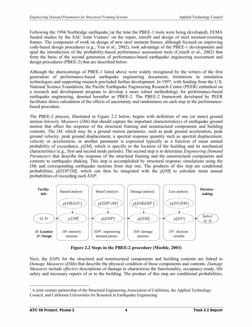
The PBEE-2 process, illustrated in Figure 2.2 below, begins with definition of one (or more) ground motion Intensity Measures (IMs) that should capture the important characteristic(s) of earthquake ground motion that affect the response of the structural framing and nonstructural components and building contents. The IM, which may be a ground motion parameter, such as peak ground acceleration, peak ground velocity, peak ground displacement, a spectral response quantity such as spectral displacement, velocity or acceleration, or another parameter is expressed typically as a function of mean annual probability of exceedance, p[IM], which is specific to the location of the building and its mechanical characteristics (e.g., first and second mode periods). The second step is to determine Engineering Demand Parameters that describe the response of the structural framing and the nonstructural components and contents to earthquake shaking. This step is accomplished by structural response simulations using the IMs and corresponding earthquake motions from step one. The products of this step are conditional probabilities, p[EDP/IM], which can then be integrated with the p[IM] to calculate mean annual probabilities of exceeding each EDP.
p[IM|O,D ]
p [IM]
IM : intensitymeasure
O, D SelectO, D
Hazard analysis Struct'l analysis
p[EDP |IM ]
p[EDP ]
EDP : engineeringdemand param.
O: LocationD: Design
Damage analysis
p[DM|EDP ]
p[DM]
DM : damagemeasure
Loss analysis
p[DV|DM ]
p[DV]
DV : decisionvariable
Decision-making
Facilityinfo
p[IM|O,D ]
p [IM]
IM : intensitymeasure
O, D SelectO, D
Hazard analysis Struct'l analysis
p[EDP |IM ]
p[EDP ]
EDP : engineeringdemand param.
O: LocationD: Design
Damage analysis
p[DM|EDP ]
p[DM]
DM : damagemeasure
Loss analysis
p[DV|DM ]
p[DV]
DV : decisionvariable
Decision-making
Facilityinfo
Figure 2.2 Steps in the PBEE-2 procedure (Moehle, 2003)
Next, the EDPs for the structural and nonstructural components and building contents are linked to Damage Measures (DMs) that describe the physical condition of those components and contents. Damage Measures include effective descriptions of damage to characterize the functionality, occupancy-ready, life safety and necessary repairs of or to the building. The product of this step are conditional probabilities,
1 A joint venture partnership of the Structural Engineering Association of California, the Applied Technology Council, and California Universities for Research in Earthquake Engineering

Engineering Demand Parameters for Structural Framing Systems Applied Technology Council
ATC-58 Project, Phase 2 5 Task 2.2 Report
p[DM|EDP], which are then integrated with p[EDP] to calculate the mean annual probability of exceedance for the DM, p[DM].
The final step in the PBEE-2 process is the calculation of Decision Variables (DVs) that serve to translate damage estimates into quantities that are useful to those tasked with making risk-related decisions. The DVs under development at this time at PEER relate to one or more of the three decision metrics identified in Figure 2.1, namely, direct dollar losses, downtime (or restoration time), and deaths (casualties). The products of this step are conditional probabilities, p[DV|DM], which are then integrated with p[DM] to calculate the mean annual probability of exceedance for the DV, p[DV].
The PBEE-2 process can be expressed in terms of a triple integral that is an application of the total probability theorem:
( ) [ ] [ ] [ ] [ ]v DV G DV DM dG DM EDP dG EDP IM d IMλ= ∫∫∫ (1)
where all terms have been defined previously. This equation, although simple and thus potentially misleading in regard to the complexity of the problem, provides an effective construct for the research and design professional community. Moehle (2003) notes that the equation “…provide[s] researchers with a clear illustration of where their discipline-specific contribution fits into the broader scheme of performance-based earthquake engineering and how their individual research results need to be presented….[ and]…emphasizes the inherent uncertainties in all phases of the problem and provides a consistent format for sharing and integrating data and models developed by researchers in the various disciplines.”
The process described in Eq. 1 and Figure 2.2 represents the detailed assessment of a building, where the building is defined in terms of all structural and nonstructural components and systems and contents. Evaluation of EDPs is an intermediate (and not final) step in performance evaluation in this PBEE-2 framework, where much emphasis is also placed on evaluating DMs and DVs2.
2.2 Review of Engineering Demand Parameters
The following sections of this chapter focus on one component of the triple integral of Equation (1), namely, EDPs. Current prescriptive seismic design procedures, and 1st generation performance-based design procedures use various EDPs as an integral part of the design process. In addition, a number of individual researchers and research projects have explored alternative EDPs that could be used to improve performance prediction and reliability. In the development of this report, contemporary seismic design codes, design guidelines and the archival literature were reviewed to identify those EDPs in use at the time of this writing or suggested for use in the future. EDPs were categorized by the authors as either direct or processed. Direct EDPs are those EDPs calculated directly by analysis or simulation and contribute to Equation (1) through [ ]p EDP IM ; example direct EDPs are interstory drift and beam plastic rotation. Processed EDPs, for example, a damage index, are derived from values of direct EDPs and data on component or system capacities. Processed EDPs could be considered either EDPs or as Damage Measures (DMs) and as such could contribute to Equation (1) through [ ]p DM EDP .
Direct EDPs are summarized in Section 2.3 for five common conventional seismic framing systems and seismic protective systems.
2 In the PBEE-1 procedures of FEMA 273 (FEMA, 1997a) and current design provisions and building codes such as the 2000 NEHRP Recommended Provisions for Seismic Regulations for Buildings and Other Structures (FEMA, 2000a), EDPs play a more central and significant role because evaluation of EDPs is the final step in the assessment or design process.

Engineering Demand Parameters for Structural Framing Systems Applied Technology Council
ATC-58 Project, Phase 2 6 Task 2.2 Report
• Reinforced concrete moment-resisting frames • Reinforced concrete or masonry structural (shear) walls • Steel moment-resisting frames • Steel braced frames (concentric and eccentric) • Timber shear walls • Protective systems
Processed EDPs are framing-system independent at this time and so are listed in Section 2.4 without reference to particular framing systems.
2.3 Direct Engineering Demand Parameters
2.3.1 Traditional EDPs
Traditional, pre-FEMA 273 (FEMA 1997a), direct Engineering Demand Parameters (EDPs) were limited to component forces and interstory displacements. These basic EDPs form the basis for design provisions contained in all contemporary and earlier building codes as well as some early seismic evaluation documents, such as Reports ATC-14 (ATC, 1985) and ATC-22 (ATC, 1988). Component forces (demands) were the key product of linear-elastic simulations that used spectral acceleration at the (approximate) fundamental period of the building, reduced by a response modification factor that was intended to account for the ductility and reserve strength in the framing system. Simulations were most commonly performed using equivalent lateral force and/or response-spectrum analysis. Indirect estimates of interstory drift were another product of the analyses. Component demands (forces) were combined with forces resulting from other loads, including dead and live, and checked against component strengths. Interstory drifts were compared to drift limits that were assumed to deliver the intended level of performance. Component capacities were established either at the strength level using materials standards such as ACI-318-02 Building Code and Commentary (ACI, 2000) and the AISC Load and Resistance Factor Design Manual (AISC, 2001), or at an allowable stress level for masonry and timber construction. This approach to seismic design is still used for new building construction. Guidelines for new building construction are presented in the NEHRP Recommended Provisions for Seismic Regulations for Buildings and Other Structures (FEMA, 2000a, 2000b), which have been adopted in the large part into ASCE-7-02, Minimum Design Loadings for Buildings and Other Structures (ASCE, 2002).
Spectral accelerations for simulations are established for a design basis earthquake for which the intended performance, albeit not explicitly checked, is Life Safety. This performance level and its corresponding damage state (in cartoon form) are shown in Figure 2.1 above that presents a capacity (pushover) curve for a sample building. The life safety (LS) performance point is shown as LS in the figure. The corresponding damage cartoon is the second of the four cartoons in the figure. General statements regarding the assumed damage at the LS level are provided in Table 2.1 in bolded text. Information in this table is drawn from multiple sources, including Comartin (2003).

Engineering Demand Parameters for Structural Framing Systems Applied Technology Council
ATC-58 Project, Phase 2 7 Task 2.2 Report
Table 2.1 Building performance levels per 2000 NEHRP and FEMA 273/274/356
Performance level Damage description Downtime/Loss
Immediate occupancy
Negligible structural damage; essential systems operational; minor overall damage 24 hours
Life safety Probable structural and nonstructural damage; no collapse; minimal falling hazards; adequate emergency egress
Possible total loss
Collapse prevention Severe structural and nonstructural damage; incipient collapse; probable falling hazards;
possible restricted access Probable total loss
The traditional force and displacement engineering demand parameters for the five framing systems and seismic protective systems are listed below. For the purpose of this presentation, those EDPs that are used in the design process contained in the 2000 NEHRP Recommended Provisions for Seismic Regulations for Buildings and Other Structures are considered traditional EDPs.
Reinforced concrete moment frames Axial force, bending moment and shear force in columns Bending moment and shear force in beams Shear force in beam-column joints Shear force and bending moments in slabs Bearing and lateral pressures beneath foundations Interstory drift (and interstory drift angle)
Reinforced concrete and masonry structural (shear) walls Axial force, bending moment and shear force in structural walls, piers and coupling elements Axial force, bending moment and shear force in columns Bending moment and shear force in beams Shear force in beam-column joints Shear force and bending moments in slabs Bearing and lateral pressures beneath foundations Interstory drift (and interstory drift angle)
Steel moment frames Axial force, bending moment and shear force in columns Bending moment and shear force in beams Shear force in beam-column joints Shear force and bending moments in slabs or other diaphragms Bearing and lateral pressures beneath foundations

Engineering Demand Parameters for Structural Framing Systems Applied Technology Council
ATC-58 Project, Phase 2 8 Task 2.2 Report
Interstory drift (and interstory drift angle)
Steel braced frames Axial force and bending moment in braces Axial force, bending moment and shear force in beams Axial force, bending moment and shear force in columns Axial force, bending moment and shear force in gusset plates Shear force and bending moments in slabs and other diaphragms Bearing and lateral pressures beneath foundations Interstory drift (and interstory drift angle) Shear force, bending moment and axial force in link elements (eccentrically braced frames only) Shear deformation in link elements (eccentrically braced frames only)
Timber structural (shear) walls Axial force, bending moment and shear force in structural walls Axial force, bending moment and shear force in columns Bending moment and shear force in beams Shear force and bending moment in diaphragms Bearing and lateral pressures beneath foundations Interstory drift (and interstory drift angle)
Seismic protective systems3 Axial force, bending moment and shear force in seismic isolators Displacement and velocity across the seismic isolation interface Axial force, bending moment and shear force in the energy dissipation devices Displacement and velocity between the ends of the energy dissipation devices
2.3.2 First Generation EDPs for Performance-based Earthquake Engineering
In the early to mid-1990s funding from the Federal Emergency Management Agency (FEMA) to the Applied Technology Council (ATC), American Society of Civil Engineers (ASCE) and the Building Seismic Safety Council (BSSC) led to the development of the NEHRP Guidelines and Commentary for Seismic Rehabilitation of Buildings (FEMA, 1997). This development effort marked a major milestone in the evolution of performance-based seismic design procedures and articulated several important earthquake-related concepts essential to a performance-based procedure. The NEHRP Guidelines and Commentary for Seismic Rehabilitation of Buildings represented the first generation of performance-based earthquake engineering assessment and design procedures, denoted herein as PBEE-1.
The key concept in the PBEE-1 was that of a performance objective, consisting of the specification of the design event (earthquake hazard), which the building is to be designed to resist, and a permissible level of damage (performance level) given that the design event is experienced. Other important features of the NEHRP Guidelines and Commentary for Seismic Rehabilitation of Buildings were the introduction of (a) 3 Only those EDPs directly associated with the protective devices are listed.

Engineering Demand Parameters for Structural Framing Systems Applied Technology Council
ATC-58 Project, Phase 2 9 Task 2.2 Report
standard performance levels, which characterized in a general manner, levels of structural and nonstructural damage based on values of standard structural response parameters, and (b) nonlinear methods of analysis and performance assessment. Figure 2.1 illustrates the qualitative performance levels of FEMA 273/274 (IO = Immediate Occupancy; LS = Life Safety; CP = Collapse Prevention) superimposed on a global force-displacement relationship for a sample building. The cartoons in the figure show the corresponding levels of damage from the onset of structural response up to the point of collapse. Brief descriptions of the building damage and business interruption (downtime) for the three FEMA 273/274 performance levels are given in Table 2.1.
Four methods of analysis were presented in the NEHRP Guidelines and Commentary for Seismic Rehabilitation of Buildings: two linear (Linear Static Procedure, Linear Dynamic Procedure) and two nonlinear (Nonlinear Static Procedure, Nonlinear Dynamic Procedure). Each method could be used to estimate the values of predictive response parameters (EDPs) for a given level of shaking (characterized by different Intensity Measures) and thus to evaluate the building’s predicted performance relative to the target performance levels. The introduction of nonlinear methods of analysis led to the development of deformation-based EDPs and acceptance criteria for those EDPs. Background information on the use of the Nonlinear Static Procedure follows. In PBEE-1, the nonlinear dynamic procedures is used in a manner similar to that illustrated for the nonlinear static procedure.
Figure 2.3 illustrates one of the nonlinear analysis and assessment procedures of FEMA 273/274: the Nonlinear Static Procedure. First, the earthquake hazard is characterized by one or more elastic acceleration response spectra. Nonlinear models of structural components are prepared for assembly into a nonlinear model of the building frame. Figure 2.4 shows an example of an idealized component nonlinear force-deformation relationship used to characterize element hysteretic behavior in this methodology.
Figure 2.3 Nonlinear static assessment procedure of FEMA 273/274/356 (FEMA, 2004)
The nonlinear building model is subjected to monotonically increasing forces or displacements to create a capacity curve (similar to Figure 2.1), which is generally plotted in terms of base shear (ordinate) versus roof displacement (abscissa). A maximum roof displacement is calculated for each design spectrum using an equivalent SDOF nonlinear representation of the building frame. Component deformation and force
Capacity curve
V
∆
NonlinearESDOF Oscillator
Story drifts and forcesδij
Component actions
δj
δi
θi
θj
Global displacement∆
Elastic spectrum

Engineering Demand Parameters for Structural Framing Systems Applied Technology Council
ATC-58 Project, Phase 2 10 Task 2.2 Report
actions for performance assessment are then established for the given roof displacement using the results of the nonlinear static analysis. Component deformation and force demands are then checked against component deformation and force capacities, which are summarized for the performance levels of Figure 2.1 in the materials chapters of FEMA 273: see IO, LS and CP in Figure 2.4b. If component demands do not exceed component capacities for the desired building performance level, the building performance objective is assumed to have been met. The Nonlinear Dynamic Procedure (NDP) of FEMA 273 differs from that shown in Figure 2.3 in that earthquake shaking is represented by earthquake histories and not response spectra, and component forces and deformations are calculated directly by nonlinear dynamic analysis and not indirectly using the results of nonlinear static analysis and simplified estimates of global nonlinear displacements. The FEMA 273 EDPs for nonlinear static analysis and nonlinear dynamic analysis are identical.
a. Component models b. Acceptance criteria
Figure 2.4 Component models for nonlinear analysis (adapted from FEMA, 2000b)
The PBEE-1 force and displacement EDPs for the five framing systems and seismic protective systems are listed below. The Prestandard and Commentary for the Seismic Rehabilitation of Buildings (FEMA, 2000f) and Evaluation of Earthquake Damaged Concrete and Masonry Wall Buildings (FEMA, 1998a) were the primary sources for the list that follows. Where applicable, the force-based EDPs that are used for both traditional analysis and PBEE-1 are listed first under each framing system and shown in italics. The deformation-based EDPs (e.g., plastic rotation angle) are for use with the nonlinear analysis procedures only.
Reinforced concrete moment frames Axial force, bending moment and shear force in columns Bending moment and shear force in beams Shear force in beam-column joints Shear force and bending moment in diaphragms Bearing and lateral pressures beneath foundations Bending moment and shear force in slabs and slab-column connections Plastic rotation angle in beams and columns Plastic rotation angle in beam-column joints Plastic rotation angle in slabs and slab-column connections
Reinforced concrete and masonry structural (shear) walls Axial force, bending moment and shear force in structural walls Axial force, bending moment and shear force in columns

Engineering Demand Parameters for Structural Framing Systems Applied Technology Council
ATC-58 Project, Phase 2 11 Task 2.2 Report
Bending moment and shear force in beams Shear force in beam-column joints Shear force and bending moment in diaphragms Bearing and lateral pressures beneath foundations Plastic rotation angle in walls and wall segments Tangential drift ratios in walls and wall segments Sliding shear displacements in walls and wall segments Chord rotations in coupling beams
Steel moment frames Axial force, bending moment and shear force in columns Bending moment and shear force in beams Shear force in beam-column panel zones Shear force and bending moment in diaphragms Bearing and lateral pressures beneath foundations Plastic rotation angle in beams and columns Plastic rotation angle in beam-column panel zones Plastic rotation angle in beam-column connections
Steel braced frames Axial force and bending moment in braces Axial force, bending moment and shear force in columns Axial force, bending moment and shear force in beams Shear force, bending moment and axial force in link elements (eccentrically braced frames only) Shear deformation in link elements (eccentrically braced frames only) Shear force and bending moment in diaphragms Bearing and lateral pressures beneath foundations Plastic deformation in braces, beams and columns Plastic rotation angle in link elements (eccentrically braced frames only)
Timber structural (shear) walls Axial force, bending moment and shear force in structural walls Axial force, bending moment and shear force in columns Bending moment and shear force in beams Shear force and bending moment in diaphragms Bearing and lateral pressures beneath foundations Normalized deformation ratio for walls, diaphragms and connections

Engineering Demand Parameters for Structural Framing Systems Applied Technology Council
ATC-58 Project, Phase 2 12 Task 2.2 Report
Seismic protective systems Axial force, bending moment and shear force in seismic isolators Displacement and velocity across the seismic isolation interface Axial force, bending moment and shear force in the energy dissipation devices Displacement and velocity between the ends of the energy dissipation devices
2.3.3 Discussion
Engineering Demand Parameters (EDPs) play a central role in both code-based design and PBEE-1 performance evaluation of building structures. In code-based design, design forces and interstory drifts are calculated using indirect (and unproven) procedures and empirical relationships. Force-based EDPs are used for component checking and system performance is judged by indirect measures of component behavior.
The development and implementation of PBEE-1 represented a paradigm shift in the practice of earthquake engineering. Traditional, indirect methods of analysis and performance assessment were supplanted by more direct (and accurate) methods. Nonlinear (and surrogate nonlinear) methods of analysis replaced the indirect elastic methods of analysis. Deformation-based performance assessment tools, capable of providing information that could be related to damage, replaced the force-based code procedures that provide no information on likely performance or damage. Although the PBEE-1 tools represent a marked improvement over traditional tools for earthquake analysis and design of building structures, many performance-related issues and shortcomings must yet be resolved, including:
1. EDP checking is undertaken at the component level and judgments on system performance are based on component assessment.
2. Insufficient attention is paid to interstory drift and floor acceleration, which are likely equal or more efficient predictors of building performance than component EDPs.
3. The performance-based acceptance criteria for components were based to a large degree on the judgment of expert engineers in the absence of experimental data.
4. The performance-based acceptance criteria were developed by engineers in the absence of significant advice from building owners and other potential users of PBEE-1 tools.
5. The EDPs used in PBEE-1 were selected on the basis of ease of calculation using analysis tools available in the mid-1990s rather than on the basis of their utility and efficiency at characterizing performance.
6. Component behavior is characterized indirectly using backbone force-displacement relationships rather than cyclic relationships that account directly for degradation of stiffness and strength.
Most of these topics are being tackled at this time through research at the NSF-funded PEER Center (www.peer.berkeley.edu).
2.4 Processed Engineering Demand Parameters
2.4.1 Introduction
Processed EDPs serve to characterize limit states of damage and structural performance and could serve as Damage Measures in the construct of Equation (1). A Damage Index (DI) can be considered to be a processed EDP. Traditionally, DIs have been used to express performance in terms of a single value between 0 (no damage) and 1 (collapse or ultimate state). An extension of this approach is the damage spectrum that takes on values between 0 (no damage) and 1 (collapse) as a function of period. Both types

Engineering Demand Parameters for Structural Framing Systems Applied Technology Council
ATC-58 Project, Phase 2 13 Task 2.2 Report
of processed EDPs are described below. Summary remarks on the utility of both processed EDPs follow the presentation.
2.4.2 Damage Indices
A Damage Index (DI) is a single-valued damage characterization for a structural component, element or framing system. A number of DIs have been proposed over the last two decades and most DIs include a linear combination of maximum displacement (deformation) response and total hysteretic energy dissipation. Williams and Sexsmith (1995) provides a detailed summary of available DIs.
The most widely known DI is that proposed by Park and Ang (1985). The Park and Ang index is calculated as a linear combination of maximum displacement response and total hysteretic energy dissipation, namely,
max
0 0
hpa
y
u EDIu F u
β= + (2)
where maxu is the maximum displacement response of the component (element, system) for a given earthquake history, ( )tℑ ; hE is the total hysteretic energy dissipated by the component (element, system) for ( )tℑ ; 0u is the maximum displacement capacity of the component (element, system) when subjected to monotonic loading; β is a calibrated constant, 0≥ ; and yF is the yield strength of the (assumed) elastic-perfectly plastic component (element, system). In this formulation, the hysteretic energy is the energy dissipated by inelastic action in the component (element, system).
Powell and Allahabadi (1988) proposed a deformation-only based damage index in terms of displacement or ductility, namely,
max max
0 0
11
yp
y
u uDI
u uµµ
− −= =
− − (3)
where maxµ is the maximum displacement ductility demand for ( )tℑ calculated by dividing the maximum displacement by the yield displacement; 0µ is the maximum displacement ductility capacity under monotonic loading, calculated by dividing the 0u by the yield displacement; and all other terms are defined above. A similar DI formulation was proposed by Cosenza et al. (1993).
Fajfar (1992) proposed an energy-only based damage index for elastic-perfectly-plastic (EPP) systems:
0 0 0
/( ) 11 1
h y yh hf
E F uEDIE
µµ µ
−= = =
− − (4)
where 0E is the hysteretic energy dissipated under monotonic loading to displacement 0µ ; hµ is the normalized hysteretic energy ductility (Mahin and Bertero, 1976); and all other terms have been defined previously. In Equation (4), the normalized hysteretic energy of Mahin and Bertero is calculated as
( /{ } 1)h h y yE F uµ = + .
Mehanny and Deierlein (2000) developed a ductility-based damage index that accounted for cumulative damage and loading history for framed buildings of conventional and composite construction:

Engineering Demand Parameters for Structural Framing Systems Applied Technology Council
ATC-58 Project, Phase 2 14 Task 2.2 Report
( )current PHC FHC,i1
FHC,i1
( ) ( )
( ) ( )
np p
in
f y pi
D
α β
θ α β
θ θ
θ θ θ
+
+
+ +
+ =
+ +
=
+ ∑=
− + ∑ (5a)
where inelastic component deformations are classed as either primary or follower cycles and are accumulated over the history of loading. In this presentation, PHC, the Primary Half Cycle, identifies a half-cycle with an amplitude (positive per Equation 5a) that exceeds all previous cycles; FHC, the Follower Half Cycle, refers to all subsequent cycles of a smaller amplitude; ( )f yθ θ +− is the plastic rotation capacity (positive direction) under monotonic loading to failure; and α and β are calibration coefficients. Damage due to deformation in the reverse (negative) direction is calculated in a similar manner and denoted Dθ
− . The two single-sided indices are combined into a single damage index as
( ) ( )D D Dγ γγ
θ θ θ+ −= + (5b)
where γ is a calibration parameter. Failure is defined when 1.0Dθ ≥ .
Bozorgnia and Bertero (2003) present a pair of DIs for generic inelastic single-degree-of-freedom systems:
1 max1 1
0 0
0.52 max2 2
0 0
(1 )( )[ ]1
(1 )( )[ ( ) ]1
e hbb
e hbb
EDIE
EDIE
α µ µ αµ
α µ µ αµ
−
−
− −= +
−− −
= +−
(6)
where 1α and 2α are calibrated coefficients with values between 0 and 1; and all other terms have been defined previously. The first index, _1bbDI is similar in structure to the Park-Ang index. The second index is intended for use with equivalent hysteretic velocity spectra as proposed by Akiyama (1985).
2.4.3 Damage Spectra
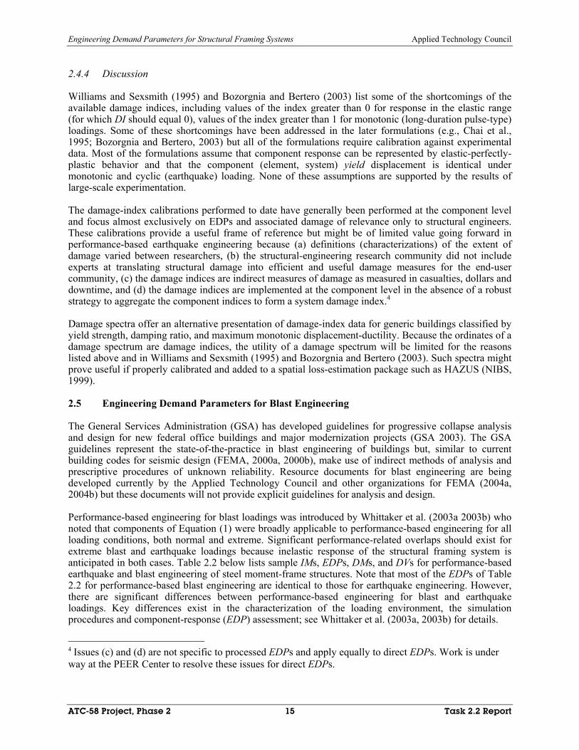
The damage spectrum of Bozorgnia and Bertero (2003) plots the damage indices of Equations (6) versus period. A sample damage spectrum is shown in Figure 2.5 for a code-compliant EPP single-degree-of-freedom system subjected to the Canoga Park earthquake history recorded during the 1994 Northridge earthquake.
Figure 2.5 Sample damage spectrum (Bozorgnia and Bertero, 2003)
Engineering Demand Parameters for Structural Framing Systems Applied Technology Council
ATC-58 Project, Phase 2 15 Task 2.2 Report
2.4.4 Discussion
Williams and Sexsmith (1995) and Bozorgnia and Bertero (2003) list some of the shortcomings of the available damage indices, including values of the index greater than 0 for response in the elastic range (for which DI should equal 0), values of the index greater than 1 for monotonic (long-duration pulse-type) loadings. Some of these shortcomings have been addressed in the later formulations (e.g., Chai et al., 1995; Bozorgnia and Bertero, 2003) but all of the formulations require calibration against experimental data. Most of the formulations assume that component response can be represented by elastic-perfectly-plastic behavior and that the component (element, system) yield displacement is identical under monotonic and cyclic (earthquake) loading. None of these assumptions are supported by the results of large-scale experimentation.
The damage-index calibrations performed to date have generally been performed at the component level and focus almost exclusively on EDPs and associated damage of relevance only to structural engineers. These calibrations provide a useful frame of reference but might be of limited value going forward in performance-based earthquake engineering because (a) definitions (characterizations) of the extent of damage varied between researchers, (b) the structural-engineering research community did not include experts at translating structural damage into efficient and useful damage measures for the end-user community, (c) the damage indices are indirect measures of damage as measured in casualties, dollars and downtime, and (d) the damage indices are implemented at the component level in the absence of a robust strategy to aggregate the component indices to form a system damage index.4
Damage spectra offer an alternative presentation of damage-index data for generic buildings classified by yield strength, damping ratio, and maximum monotonic displacement-ductility. Because the ordinates of a damage spectrum are damage indices, the utility of a damage spectrum will be limited for the reasons listed above and in Williams and Sexsmith (1995) and Bozorgnia and Bertero (2003). Such spectra might prove useful if properly calibrated and added to a spatial loss-estimation package such as HAZUS (NIBS, 1999).
2.5 Engineering Demand Parameters for Blast Engineering
The General Services Administration (GSA) has developed guidelines for progressive collapse analysis and design for new federal office buildings and major modernization projects (GSA 2003). The GSA guidelines represent the state-of-the-practice in blast engineering of buildings but, similar to current building codes for seismic design (FEMA, 2000a, 2000b), make use of indirect methods of analysis and prescriptive procedures of unknown reliability. Resource documents for blast engineering are being developed currently by the Applied Technology Council and other organizations for FEMA (2004a, 2004b) but these documents will not provide explicit guidelines for analysis and design.
Performance-based engineering for blast loadings was introduced by Whittaker et al. (2003a 2003b) who noted that components of Equation (1) were broadly applicable to performance-based engineering for all loading conditions, both normal and extreme. Significant performance-related overlaps should exist for extreme blast and earthquake loadings because inelastic response of the structural framing system is anticipated in both cases. Table 2.2 below lists sample IMs, EDPs, DMs, and DVs for performance-based earthquake and blast engineering of steel moment-frame structures. Note that most of the EDPs of Table 2.2 for performance-based blast engineering are identical to those for earthquake engineering. However, there are significant differences between performance-based engineering for blast and earthquake loadings. Key differences exist in the characterization of the loading environment, the simulation procedures and component-response (EDP) assessment; see Whittaker et al. (2003a, 2003b) for details.
4 Issues (c) and (d) are not specific to processed EDPs and apply equally to direct EDPs. Work is under way at the PEER Center to resolve these issues for direct EDPs.

Engineering Demand Parameters for Structural Framing Systems Applied Technology Council
ATC-58 Project, Phase 2 16 Task 2.2 Report
Table 2.2 Sample IMs, EDPs, DMs and DVs for performance-based engineering of steel moment frames for earthquake and blast loadings (adapted from Whittaker et al., 2003a, 2003b)
Earthquake engineering Blast engineering
Intensity Measures Peak ground acceleration Spectral acceleration at T1 Spectral acceleration at T1 and T2
Charge weight and standoff
Charge weight and location
Engineering Demand Parameters
Demand-to-capacity ratios Beam plastic rotation angle Beam-column connection rotation angle Panel zone rotation angle Beam shear Column axial load, moment, shear Column plastic rotation angle Inter-story drift
Demand-to-capacity ratios Beam plastic rotation angle Beam-column connection rotation angle Beam shear, axial load, torque Beam twist rotation angle Panel zone rotation angle Column axial load, moment, shear Column plastic rotation angle Floor vertical displacement
Damage Measures Casualties Dollars Downtime
Casualties Dollars Downtime
Decision Variables Annualized loss Performance objective
Performance objective

Engineering Demand Parameters for Structural Framing Systems Applied Technology Council
ATC-58 Project, Phase 2 17 Task 2.2 Report
3. BIBLIOGRAPHY
Akiyama, H., 1985, Earthquake-Resistant Limit-State Design For Buildings, University of Tokyo Press, Tokyo.
ACI, 2002, ACI-318-02 Building Code and Commentary, American Concrete Institute, Farmington Hills, Michigan.
AISC, 2001, Manual of Steel Construction, Load and Resistance Factor Design, 3rd Edition, American Institute of Steel Construction, Chicago, Illinois.
ASCE, 2002, Minimum Design Loadings for Buildings and Other Structures, ASCE-7-02, American Society of Civil Engineers, Reston, Virginia.
ATC, 1985, Evaluation of the Seismic Resistance of Buildings, Applied Technology Council, Report No. ATC-14, Redwood City, California.
ATC, 1988, A Handbook for Seismic Evaluation of Existing Buildings, Applied Technology Council, Report No. ATC-22, Redwood City, California.
ATC, 1996, Seismic Evaluation and Retrofit of Concrete Buildings, Applied Technology Council, Report No. ATC-40, Redwood City, California.
Biggs, J., 1964, Introduction to Structural Dynamics, McGraw Hill, New York, N.Y. Bozorgnia, Y. and V. V. Bertero, 2003, “Damage spectra: characteristics and applications to seismic risk
reduction.” J. Struct. Eng., Vol. 129, No. 10, pp. 1330-1340. Comartin, C., 2003. Personal Communication. Conrath, E. J., T. Krauthammer, K. A. Marchand, and P. F. Mlakar, 1999, Structural Design for Physical
Security, American Society of Civil Engineers, Reston, Virginia. Cornell, C. A., F. Jalayer, R. O. Hamburger, and D. A. Foutch, 2002, “Probabilistic basis for 2000 SAC
Federal Emergency Management Agency steel moment frame guidelines,” Journal of Structural Engineering, Vol. 128, No. 4, pp. 526-533.
Cosenza, E., G. Manfredi and R. Ramasco, 1993, “The use of damage functionals in earthquake engineering: a comparison between different methods,” Earthquake Eng. Struct. Dyn., Vol. 22, pp 855-868.
Deierlein, G. and S. Hamilton, 2003, “Framework for structural fire engineering and design methods,” Proceedings, NIST-SFPE Workshop on National R&D Road Map for Fire Safety Design and Retrofit of Structures, Baltimore, Maryland.
Fajfar, P., 1992, “Equivalent ductility factors, taking into account low-cycle fatigue,” Earthquake Eng. Struct. Dyn., Vol. 21, pp 837-848.
FEMA, 1996, Performance Based Seismic Design of Buildings, Federal Emergency Management Agency, Report No. FEMA 283, Washington, D.C.
FEMA, 1997a, NEHRP Guidelines for the Seismic Rehabilitation of Buildings, prepared by the Applied Technology Council for the Building Seismic Safety Council, published by the Federal Emergency Management Agency, Report No. FEMA 273, Washington, D.C.
FEMA, 1997b, NEHRP Commentary on the Guidelines for the Seismic Rehabilitation of Buildings, prepared by the Applied Technology Council for the Building Seismic Safety Council, published by the Federal Emergency Management Agency, Report No. FEMA 274, Washington, D.C.
FEMA, 1998a, Evaluation of Earthquake Damaged Concrete and Masonry Wall Buildings - Basic Procedures Manual, prepared by the Applied Technology Council for the Partnership for Response
Engineering Demand Parameters for Structural Framing Systems Applied Technology Council
ATC-58 Project, Phase 2 18 Task 2.2 Report
and Recovery, published by the Federal Emergency Management Agency, Report No. FEMA 306, Washington, DC.
FEMA, 1998b, Evaluation of Earthquake Damaged Concrete and Masonry Wall Buildings - Technical Resources, prepared by the Applied Technology Council for the Partnership for Response and Recovery, published by the Federal Emergency Management Agency, Report No. FEMA 307, Washington, D.C.
FEMA-308, 1998, Repair of Earthquake Damaged Concrete and Masonry Wall Buildings, prepared by the Applied Technology Council for the Partnership for Response and Recovery, published by the Federal Emergency Management Agency, Report No. FEMA 308, Washington, D.C.
FEMA, 2000a, NEHRP Recommended Provisions for Seismic Regulations for Buildings and Other Structures, Part 1, Provisions, prepared by the Building Seismic Safety Council, published by the Federal Emergency Management Agency, Report No. FEMA 368, Washington, D.C.
FEMA, 2000b, NEHRP Recommended Provisions for Seismic Regulations for Buildings and Other Structures, Part 2, Commentary, prepared by the Building Seismic Safety Council, published by the Federal Emergency Management Agency, Report No. FEMA 369, Washington, D.C.
FEMA, 2000c, Action Plan for Performance Based Seismic Design, prepared by the Earthquake Engineering Research Institute, published by the Federal Emergency Management Agency, Report No. FEMA 349, Washington, D.C.
FEMA, 2000d, Recommended Seismic Design Criteria for New Steel Moment-Frame Buildings, prepared by the SAC Joint Venture, a partnership of the Structural Engineers Association of California, the Applied Technology Council, and Universities for Research in Earthquake Engineering, published by the Federal Emergency Management Agency, Report No. FEMA 350, Washington, DC.
FEMA, 2000e, Recommended Seismic Evaluation and Upgrade Criteria for Existing Welded Steel Moment-Frame Buildings, prepared by the SAC Joint Venture, a partnership of the Structural Engineers Association of California, the Applied Technology Council, and Universities for Research in Earthquake Engineering, published by the Federal Emergency Management Agency, Report No. FEMA 351, Washington, D.C.
FEMA, 2000f, Prestandard and Commentary for the Seismic Rehabilitation of Buildings, prepared by the American Society of Civil Engineers, published by the Federal Emergency Management Agency, Report No. FEMA 356, Washington, D.C.
FEMA, 2004a, Reference Manual to Mitigate Potential Terrorist Attacks Against Buildings, in preparation, prepared by UTD, Inc., published by the Federal Emergency Management Agency, Report No. FEMA 426, Washington, D.C.
FEMA, 2004b, Primer for the Design of Commercial Buildings to Resist Terrorist Attacks, prepared by the Applied Technology Council, published by the Federal Emergency Management Agency, Report No. FEMA 427, Washington, D.C.
FEMA, 2004c (in preparation), Improvement of Seismic Inelastic Analysis Procedures, prepared by the Applied Technology Council, published by the Federal Emergency Management Agency, Report No. FEMA 440, Washington, D.C.
GSA, 2003, GSA Progressive Collapse Analysis and Design Guidelines for New Federal Office Buildings and Major Expansion Projects, prepared by Applied Research Associates for the General Services Administration, Washington, D.C.
Hamburger, R. O., 2003, A Vision for Performance Based Earthquake Engineering, Unpublished report for the ATC-58 project, Applied Technology Council, Redwood City, California.
Mahin, S. A. and V. V. Bertero, 1981, “An evaluation if inelastic seismic design spectra,” J. Struct. Div., Vol. 107, No. 9, pp. 1777-1795.

Engineering Demand Parameters for Structural Framing Systems Applied Technology Council
ATC-58 Project, Phase 2 19 Task 2.2 Report
Mays, G. C. and P. D. Smith (ed.), 1995, Blast Effects on Buildings, Telford Publications, London, United Kingdom.
Mehanny, S. and G. G. Deierlein, 2000, “Assessing seismic performance of composite (RCS) and steel moment framed buildings,” Proceedings, 12th World Conference on Earthquake Engineering, Auckland, New Zealand.
Moehle, J. P., 2003, “A framework for performance-based earthquake engineering,” Proceedings, Tenth U.S.-Japan Workshop on Improvement of Building Structural Design and Construction Practices, Applied Technology Council, Report ATC-15-9, Redwood City, California.
NIBS, 1999, HAZUS Technical Manual, SR2 edition, Vols. I, II, and III, prepared by the National Institute of Building Sciences for the Federal Emergency Management Agency, Washington, D.C.
Park, Y. J. and A. H.-S Ang,, 1985, “Mechanistic seismic damage model for reinforced concrete.” J. Struct. Eng., Vol. 111, No. 4, pp. 722-739.
Powell, G.H. and R. Allahabadi, 1988, “Seismic damage prediction by deterministic methods: concepts and procedures,” Earthquake Eng. Struct. Dyn., Vol. 16, pp 719-734.
SEAOC, 1995, Performance Based Seismic Engineering of Buildings, Structural Engineers Association of California, Volumes I and II, Sacramento, California.
Whittaker, A. S., R. O. Hamburger, C. Comartin, R. Bachman and C. Rojahn, 2003a, “Performance based engineering of building structures,” Proceedings, 73rd Shock and Vibration Symposium, SAVIAC, San Diego, California.
Whittaker, A. S., R. O. Hamburger, and M. Mahoney, 2003b, “Performance based engineering of buildings for extreme events,” Proceedings, AISC-SINY Symposium on Resisting Blast and Progressive Collapse, American Institute of Steel Construction, New York, New York.
Williams, M. S. and R. G. Sexsmith, 1995, “Seismic damage indices for concrete structures: a state-of-the-art review,” Earthquake Spectra, Volume 11, No. 2, pp. 319-349.
Yun, S.-Y., R. O. Hamburger, C. A. Cornell and D. A. Foutch, 2002, “Seismic performance evaluation for steel moment frames,” Journal of Structural Engineering, Vol. 128, No. 4, pp. 534-545.