Embed Size (px)
Citation preview

GPS & External Sensors Guide for the AT&T Cellular IoT Kit
Version 1.0
1 September 2016
P a g e 2 | 29
Table of Contents
1 Reference documents ................................................................................................................................................ 5
2 Introduction ............................................................................................................................................................... 6
3 Supported Sensors ..................................................................................................................................................... 7
3.1 Sensors that are part of the AT&T Cellular IoT Kit ............................................................................. 7
3.2 External Sensors via the PMOD (J10 on the Cellular Shield).............................................................. 7
3.3 Virtual Sensors via the FRDM-K64F USB connector, J26 ................................................................... 7
4 I2C connections .......................................................................................................................................................... 8
5 I2C Interface ............................................................................................................................................................... 9
5.1 I2C Specifics for mbed ........................................................................................................................ 9
5.2 Sensor I2C slave addresses ................................................................................................................ 9
5.2.1 FXOS8700 Motion sensor I2C slave address .............................................................................. 9
5.2.2 HTS221 Temperature and Humidity sensor I2C slave address .................................................. 9
5.2.3 Xadow GPS I2C slave address ................................................................................................... 10
5.2.4 Si1145 proximity and light sensor I2C slave address ............................................................... 10
5.2.5 Si7020 temperature and humidity sensor I2C slave address ................................................... 10
6 Sensor descriptions .................................................................................................................................................. 11
6.1 FXOS8700CQ motion sensor ............................................................................................................ 11
6.1.1 Accelerometer .......................................................................................................................... 11
6.1.2 Magnetometer ......................................................................................................................... 11
6.2 HTS221 Temperature and Humidity sensor ..................................................................................... 12
6.3 Xadow GPS ....................................................................................................................................... 13
6.3.1 GPS I2C Interface ...................................................................................................................... 14
6.3.2 GPS commands ........................................................................................................................ 14
6.3.3 GPS initialization time .............................................................................................................. 14
6.3.4 Waiting for GPS initialization ................................................................................................... 15
6.3.5 Wiring up the Xadow GPS module to the PMOD connector ................................................... 17
6.3.6 Wiring up the Xadow GPS module to the Arduino-compatible interface................................ 21
6.4 Silicon Labs Sensor PMOD ................................................................................................................ 22
6.4.1 Si1145 proximity and light sensor ............................................................................................ 22
6.4.2 Si7020 temperature and humidity sensor ............................................................................... 22

P a g e 3 | 29
6.4.3 Wiring up the SiLabs PMOD Sensor to the PMOD connector .................................................. 23
6.5 Sensor Simulator Windows utility .................................................................................................... 24
6.5.1 Why virtual sensors? ................................................................................................................ 24
6.5.2 Installing and running the Sensor Simulator utility ................................................................. 25
6.5.3 Resolving problems with running the Sensor Simulator utility ............................................... 25
6.5.3.1 Microsoft .NET Framework version ..................................................................................... 25
6.5.3.2 Show Debug ......................................................................................................................... 25
6.5.4 Setting virtual sensor values .................................................................................................... 26
6.5.5 Sending virtual sensor values over USB and the update rate .................................................. 26
6.5.6 Modifying virtual sensor names, units and ranges .................................................................. 27
7 Modifying the mbed project for the FRDM-K64F .................................................................................................... 28
7.1 Default sensors to report to the Flow Designer .............................................................................. 28
7.2 Reporting, also, GPS readings to Flow Designer .............................................................................. 29
7.3 Reporting PMOD Sensor and Virtual Sensor readings to Flow Designer ......................................... 29

P a g e 4 | 29
Revision History
Document Version: Version 1.0 Document Date: 1 September 2016 Prior Version History: Version: Date: Comment:
1.0 2016/09/01 Initial Release
Comments:

P a g e 5 | 29
1 Reference documents
Please follow the hyperlinks below to open the relevant reference documents. At the time of the writing of this document these links were active but in time some content could move or change.
[1] Avnet’s AT&T Cellular IoT Kit Getting Started Guide
[2] NXP’s FRDM-K64F development platform
[3] NXP’s FXOS8700CQ 6-axis sensor with integrated linear accelerometer and magnetometer
[4] STMicroelectronics HTS221 Capacitive digital sensor for relative humidity and temperature
[5] Seeed Studio’s Xadow GPS module v2
[6] Quectel’s L70-R GPS Specification
[7] NXP’s Kinetis KL02 microcontroller
[8] Silicon Labs Sensor PMOD
[9] Silicon Labs Si7020 Humidity and Temperature Sensor
[10] Silicon Labs Si1145 Proximity, UV and Ambient Light Sensor

P a g e 6 | 29
2 Introduction
This document is a companion guide for the “AT&T Cellular IoT Kit Getting Started Guide” [1]. The Getting Started Guide refers to the ability of the reference design to support the use of external sensors. More detail on how to use these sensors can be found here. The use of the following is discussed:
• A Xadow GPS module that can provide location and movement information extracted from visible satellites
• A Silicon Labs PMOD module that can provide proximity and light readings
• A Windows utility that can be used to simulate sensors in a test environment
Since this is not discussed elsewhere, some details on the on-board FXOS8700CQ motion sensor on the FRDM-K64F base board [2] and the HTS221 humidity and temperature sensor on the cellular shield are also given in this document.

P a g e 7 | 29
3 Supported Sensors
The Avnet software reference design for the AT&T Cellular IoT Kit is an mbed project that is described in the Getting Started Guide (see [1]). This design currently supports a number of hardware sensors that communicate using the I2C protocol as well as 8 virtual sensors via a USB UART.
3.1 Sensors that are part of the AT&T Cellular IoT Kit
• NXP FXOS8700CQ 6-axis Accelerometer & Gyrometer
FRDM-K64F base board:
• ST Micro HTS221 Temperature & Humidity
Cellular shield:
3.2 External Sensors via the PMOD (J10 on the Cellular Shield)
Seeed Studio Xadow GPS v2
• Latitude, Longitude, Altitude, Speed, Direction & Time
:
SiLabs Sensor PMOD
• Proximity, Ambient light, UV index, Temperature & Humidity
(Si1145 + Si7020):
3.3 Virtual Sensors via the FRDM-K64F USB connector, J26
“Sensor Simulator” Windows utility
• 4 switches, 2 sliders, 2 dials and a text string
:

P a g e 8 | 29
4 I2C connections The K64F processor communicates with sensors using two separate I2C busses. Each I2C bus consists of two signals, i.e. a data line (SDA) and a clock (SCL).
• “I2C0” has SDA on pin PTE25 and SCL on pin PTE24 of the CPU. • “I2C1” has SDA on pin PTC11 and SCL on pin PTC10 of the CPU.
I2C0 goes to the FXOS8700CQ motion sensor on the FRDM-K64F base board. It also goes to the WNC modem device on the cellular shield. This I2C connection to the WNC device is not currently used.
Note:
I2C1 goes to the HTS221 temperature and humidity sensor on the cellular shield. It also goes to the PMOD socket, J10, on the cellular shield.
When you look at the I2C0 bus during startup, you will see that the WNC device puts a single byte, 0x94, on the bus. This is an attempted write to slave address 0x4C, to a device that does not exist on the bus. Since it does not respond there is no further I2C communication from the WNC modem. The mbed OS can interpret this operation of the IC2 clock as a sign that it is a slave on the bus though. For this reason it is important that any code that uses this I2C bus is only initialized after the WNC initialization is done.
Both these I2C busses can also be accessed via the Arduino-compatible interface pins on the connectors, as indicated in the diagram below.

P a g e 9 | 29
5 I2C Interface 5.1 I2C Specifics for mbed
The default mbed I2C interface clock rate is 100 kHz. If you want to operate at a different frequency, you can use the i2c.frequency(int Hz) function.
Note that mbed uses the I2C slave address in a way that can be considered to be unusual. The first byte AAAAAAADb of an I2C access usually consists of a 7-bit address in the most significant bits followed by a direction bit (0 for write, 1 for read). In the mbed i2c.write() and i2c.read() commands, the 8-bit I2C slave address is the specified slave address << 1. If the sensor datasheet therefore specifies that its I2C address is 0x30, the mbed write would be i2c.write(0x70, …..) and the read will be i2c.write(0x70, ….) and what you see on the bus would be an 0x70 for a write and an 0x71 for a read.
5.2 Sensor I2C slave addresses 5.2.1 FXOS8700 Motion sensor I2C slave address
The default I2C address of the on-board FXOS8700CQ motion sensor is 0x1D, which means that 0x1D << 1 is passed to the mbed I2C interface. A different I2C address can be selected by changing the resistors on the FRDM-K64F board as per the schematic.
5.2.2 HTS221 Temperature and Humidity sensor I2C slave address
The I2C address for the HTS221 sensor on the cellular shield is defined by the datasheet [4] as 0xBE for write and as 0xBF for read. Either of these can be passed to the mbed I2C interface, as it will use the correct direction bit. This also implies that the 7-bit I2C address is actually 0x5F.

P a g e 10 | 29
5.2.3 Xadow GPS I2C slave address
The external Seeed Studio GPS v2 module uses a GPS L70 module from Quectel that is controlled via UART from an NXP Kinetis KL02 microcontroller. The I2C address of the KL02 device is set to 0x05, which means that 0x05 << 1 = 0x0A is passed to the mbed I2C interface. A diagram in paragraph 6.3.1 illustrates this connection.
5.2.4 Si1145 proximity and light sensor I2C slave address
The I2C address of the Si1145 proximity and light sensor on the Silicon Labs PMOD is 0x60, which means that 0x60 << 1 = 0xC0 is passed to the mbed I2C interface.
5.2.5 Si7020 temperature and humidity sensor I2C slave address
The I2C address of the Si7020 temperature and humidity sensor on the Silicon Labs PMOD is 0x40, which means that 0x40 << 1 = 0x80 is passed to the mbed I2C interface.

P a g e 11 | 29
6 Sensor descriptions
This section gives more information on the various sensors.
6.1 FXOS8700CQ motion sensor
NXP’s FXOS8700CQ 6-axis sensor with integrated linear accelerometer and magnetometer (see [3]) provides 3-azis (X, Y and Z) acceleration information, as well as 3-axis (X, Y and Z) magnetometer information.
6.1.1 Accelerometer
Acceleration in each axis is a 14-bit 2’s complement number. To convert this number to g’s, the application code divides it by 2048 (0x800). The output of the reference design code is therefore in g’s, where one g is the gravitational acceleration of the Earth, 9.80665 m/s2. In terms of the IC as it is mounted on the board, the acceleration axes are as in the diagram below:
6.1.2 Magnetometer
The magnetometer reading in each axis is a 16-bit 2’s complement number. Each number represents an angle from 0 to 360 degrees. So in each axis it can be seen that you have a “compass”. In three dimensions these angles are referred to as Roll, Pitch and Yaw as defined in the Wikipedia image below.

P a g e 12 | 29
Before the magnetometer reading can be trusted though, it needs some calibration. This typically involves moving the sensor in a figure 8 pattern for a while. Because this is a complication for stationary code development, the magnetometer information is read, but is not currently used or communicated by the reference design.
6.2 HTS221 Temperature and Humidity sensor The HTS221 by STMicroelectronics is a compact digital sensor that reads relative humidity and temperature (see [4]). It is mounted on the cellular shield. Here are some specifications:
• 0 to 100% relative humidity range • Supply voltage: 1.7 to 3.6 V • Low power consumption: 2 μA @ 1 Hz ODR • Selectable ODR from 1 Hz to 12.5 Hz • High rH sensitivity: 0.004% rH/LSB • Humidity accuracy: ± 3.5% rH, 20 to +80% rH • Temperature accuracy: ± 0.5 °C,15 to +40 °C • 16-bit humidity and temperature output data • SPI and I²C interfaces • Tiny 2 x 2 x 0.9 mm package
Temperature readings are in Celsius but are converted to Fahrenheit by the application code.

P a g e 13 | 29
6.3 Xadow GPS
The Seeed Studio GPS v2 module (see [5]) uses a GPS L70 module from Quectel (see [6]). The GPS is controlled via UART from an NXP Kinetis KL02, which is a Cortex-M0 microcontroller (see [7]). The module features an integrated chip antenna. There are miniature Xadow connectors also that can be used for prototyping compact systems. This reference design does not use those connectors.
Here are some specifications:
• Power Supply: 3.3 – 6 V (via breakout pins) • Clock Speed: 48 MHz • Power Consumption: 18mA@Tracking, 21mA@Acquisition • Power Saving: Typ. 3mA@AlwaysLocateTM, 7uA@Backup Mode, 180uA@Standby Mode • Channel: 22(Tracking) / 66 (Acquisition) • Update Rate: 1Hz(Default), up to 10Hz • Horizontal Position Accuracy:<2.5m CEP • Velocity Accuracy:<0.1m/s • Maximum Velocity: Max.515m/s • Cold/warm start with EASYTM: 15s/5s • Acquisition Sensitivity: -145dBm • Tracking Sensitivity: -163dBm • Operating Temperature: -40 to 85 • Protocols: NMEA 0183/PMTK • Antenna Type: Chip antenna • Interface: Interface with Xadow GSM+BLE through I2C (7-bit address 0x05) • Dimensions: 25.37mm X 20.30mm / 1’’ X 0.8’’

P a g e 14 | 29
6.3.1 GPS I2C Interface
Note that the FRDM-K64F board does not communicate with the GPS directly. It uses I2C to communicate with the Cortex-M0 on the Xadow module, which in turn communicates with the L70 GPS via a UART.
6.3.2 GPS commands
The GPS module has commands for extracting the following:
• GPS status: 'A' = Valid, 'V' = Invalid • Satellites used: A number between 0 and 66 • UTC (Coordinated Universal Time) date and time • Latitude in degrees and minutes • Longitude in degrees and minutes • Altitude in meters • Speed (over ground) in knots • Course in degrees
6.3.3 GPS initialization time
After power-up, the Xadow GPS module will start responding to I2C messages within seconds, but it takes a while before the GPS readings are valid. Ideally, the GPS should have an open view of the sky to track visible satellites. If the GPS is used indoors, the walls and roofing should be permeable enough to still allow satellites to be tracked.
From indoors testing with the GPS module and cellular shield it appears that it can take from less than 5 minutes to 20 minutes for the GPS to acquire enough satellites for valid readings after a cold boot. After a warm boot, re-connection is immediate. It seems that more than 12 satellites are not typically tracked and that for readings to be valid, at least 6 satellites have to be used.

P a g e 15 | 29
6.3.4 Waiting for GPS initialization
While the GPS is attempting to connect, the reference design application displays a ‘V’ and the number of satellites it is seeing. A status update is obtained every 5 seconds. When that ‘V’ changes to an ‘A’, it means that the GPS readings are valid.
Cold boot:

P a g e 16 | 29
Warm boot:

P a g e 17 | 29
6.3.5 Wiring up the Xadow GPS module to the PMOD connector
Four signals have to be connected between the Cellular kit and the Xadow GPS module. Silkscreen text on the back side of the GPS board identifies the signals for the holes. On the PMOD, J10 on the cellular shield, pin 1 is the pin closest to the antenna bulkhead connectors.
Signal J10 PMOD (Shield) Xadow GPS hole Color in the image below
VCC Pin 6 VCC Red
GND Pin 5 GND Black
SDA Pin4 SDA Green
SCL Pin3 SCL Yellow
There are a number of ways to make these connections on the GPS side and the photographs below show some examples.
IC grabbers:

P a g e 18 | 29
IC grabbers close-up:
Header pins with jumper wires:

P a g e 19 | 29
Soldered wires:

P a g e 20 | 29
The two images below show how the GPS module can be wired to plug directly into a PMOD socket:

P a g e 21 | 29
6.3.6 Wiring up the Xadow GPS module to the Arduino-compatible interface
If you do not have a shield or are using the shield PMOD for another purpose, you can also use the Arduino-compatible interface pins to connect. J4 pin 12 is closest to the RGB LED on the K64F board:
Signal Arduino pins Xadow GPS hole Color in the image
VCC e.g. J3 pin 4 VCC Red
GND e.g. J3 pin 14 GND Black
SDA J4 pin 10 SDA Green
SCL J4 pin 12 SCL Yellow

P a g e 22 | 29
6.4 Silicon Labs Sensor PMOD
The Silicon Labs Sensor PMOD (see [8]) has two I2C sensors mounted on it, i.e. the Si1145 proximity and light sensor and the Si7020 temperature and humidity sensor. The Si7020 has a testing feature, an internal heater element that can be used to “raise” the measured temperature when it is turned on.
When the PMOD is connected, the reference design reads both these sensors, but the Si7020 temperature and humidity readings are not used because the HTS221 sensor on the cellular shield already provides temperature and humidity.
6.4.1 Si1145 proximity and light sensor
The Si1145 (see [10]) is a low-power, reflectance-based proximity and light sensor in a 2x2mm package that can provide:
• Proximity detection adjustable from under 1 cm to over 50 cm • Ambient light lux measurements with an IR correction algorithm • UV index sensor
The application code reads the relevant registers and scales them as required. For the proximity sensor, values can be interpreted as follows:
• value < 22000 : Object Far • 22000 ≤ value < 24000 : Object in Vicinity • 24000 ≤ value < 30000 : Object Near • value ≥ 30000 : Object Very Near
6.4.2 Si7020 temperature and humidity sensor
The Si7020 (see [9]) is a relative humidity (0–80% ± 4%) and temperature (-10 to 85 degrees Celsius) sensor in a 3x3mm package.
The application code reads the relevant registers and scales them as required.

P a g e 23 | 29
6.4.3 Wiring up the SiLabs PMOD Sensor to the PMOD connector
Please note that the PMOD cannot be plugged directly into the PMOD connector, as the pinouts do not match. Four signals have to be connected between the Cellular kit and the SiLabs PMOD. Silkscreen text on the top side of the PMOD board identifies the signals. On the PMOD socket, J10 on the cellular shield, pin 1 is the pin closest to the antenna bulkhead connectors.
Signal J10 (Shield) SiLabs PMOD Color in the image below VCC Pin 6 Pin 6 Red GND Pin 5 Pin 5 Black SDA Pin4 Pin 3 Green SCL Pin3 Pin 2 Yellow

P a g e 24 | 29
6.5 Sensor Simulator Windows utility 6.5.1 Why virtual sensors?
For testing and demonstration purposes, it is often useful to specify exactly what a sensor reading should be or to emulate a sensor that you do not yet have access to. With this in mind Avnet created an executable that runs on a Windows PC and provides 8 virtual sensors. Each sensor can be configured to match your system in terms of units and range. When the PC is connected to the FRDM-K64F board via USB, the reference design automatically gets updates from the virtual sensors in the form of a simple text string that contains their values.

P a g e 25 | 29
6.5.2 Installing and running the Sensor Simulator utility
Download the .zip file in the link below and unzip it to a location on your PC from which you have permission to run executables. If you are not logged into cloudconnectkits.org, you will have to log in first or create a free account if you do not have one. The file is available on the Cellular IoT Starter Kit page under the “Startup Files & Reference Designs” tab or directly at:
http://cloudconnectkits.org/system/files/SensorSimulator_0.zip
Close all terminal programs (like PuTTY) that are communicating with your FRDM-K64F board over USB. Now double-click SensorSimulator.exe in the extracted folder. Make sure the port number matches that of
the board and that the baudrate is 115200, then click in the top left.
6.5.3 Resolving problems with running the Sensor Simulator utility 6.5.3.1 Microsoft .NET Framework version
If you get a Windows error when running the utility, it is possible that you do not have the latest version of the .NET framework installed on your machine. This is a C# implementation developed under Microsoft Visual Studio Community and it expects a minimum .NET framework version of 4.5.2 to run.
You can install the latest .NET version by searching for it. Currently it is version 4.6.2 that is available at
Microsoft .NET Framework 4.6.2
If you are unsure of which version of .NET you currently have installed, you can enter the command below at a command prompt and it will list the versions that are installed on your machine.
dir %WINDIR%\Microsoft.Net\Framework\v*
6.5.3.2 Show Debug
Also, the utility takes the place of the USB serial debug terminal. You can still view debug information by checking the “Show Debug” checkbox. But if the amount of debug information is too much and too fast, the current application may hang. It is therefore suggested not to use this checkbox with constant high volume streams of debug text.

P a g e 26 | 29
6.5.4 Setting virtual sensor values
The sensors can be changed by dragging them with the mouse, which is intuitive. The two dials on the right can be “turned” most easily by clicking on one and then using the mouse scroll wheel, if available, to turn it up or down. You can also use your laptop’s touchpad to scroll by using a two-finger scroll gesture.
For each of the two vertical slider sensors, there is an “Add random” checkbox. This can be used to add some dithering or noise to the sensor value. The amount of randomness added can be modified in the adjacent numeric up/down box.
6.5.5 Sending virtual sensor values over USB and the update rate
From the sensor settings, a string with all the sensor values is composed that can be sent to the board via USB. This is the “To board” string in the image below. This can be done manually, by clicking the “Send All” button, or by checking the “Auto-Send all” box to its right. To change the update interval, un-check the box, change the interval value and then re-check the box again.
Note that in addition to the 8 virtual sensor values, a text string can also be sent to the board. This can be used to simulate some sort of USB text input to the board. The “To board” string is received and decoded in the parse_usbhost_message() routine in sensors.cpp in the mbed project. If you do not want to use virtual sensors or want to use the USB receive path for a different purpose, you can comment out #define USE_VIRTUAL_SENSORS in the hardware.h file.

P a g e 27 | 29
6.5.6 Modifying virtual sensor names, units and ranges
Every time the executable is closed, a .ini file is saved with the last settings and selections. When the program is not running, the values in this file can be edited using, for example, Notepad.
Here the user can specify:
• Whether a sensor is enabled (displayed on the GUI) or not • A name for each sensor, e.g. “Light Sensor” • A unit of measure for each sensor, e.g. “lux” • A minimum and maximum value for the slider and dial sensors • A default value for each sensor and selection (this will be updated when the program closes)

P a g e 28 | 29
7 Modifying the mbed project for the FRDM-K64F
In the config_me.h header file in the mbed project, the iSensorsToReport variable can be modified to specify which parameters get reported to the AT&T Flow Designer.
7.1 Default sensors to report to the Flow Designer
The default assignment for this variable (shown above) is: iSensorsToReport = TEMP_HUMIDITY_ACCELEROMETER; With this setting, the board reports readings from the HTS221 temperature & humidity sensor and 3-axis accelerometer readings from the FXOS8700CQ motion sensor. These values are sent to the HTTP IN /climate port in Flow with field names temp, humidity, accelX, accelY and accelZ.
If you have your mbed IoT Cellular Kit running and connected to the AT&T Flow Designer, debug messages from the HTTP GET input should be visible in Flow. If you look at these debug messages, you will see that they contain the information for these sensor readings in a JSON string:
"temp": "93.12", "humidity": "57", "accelX": "-0.007", "accelY": "-0.025", "accelZ": "0.988"
The image below illustrates how this appears when viewed in the “Debug” tab at the bottom of the Flow canvas.
P a g e 29 | 29
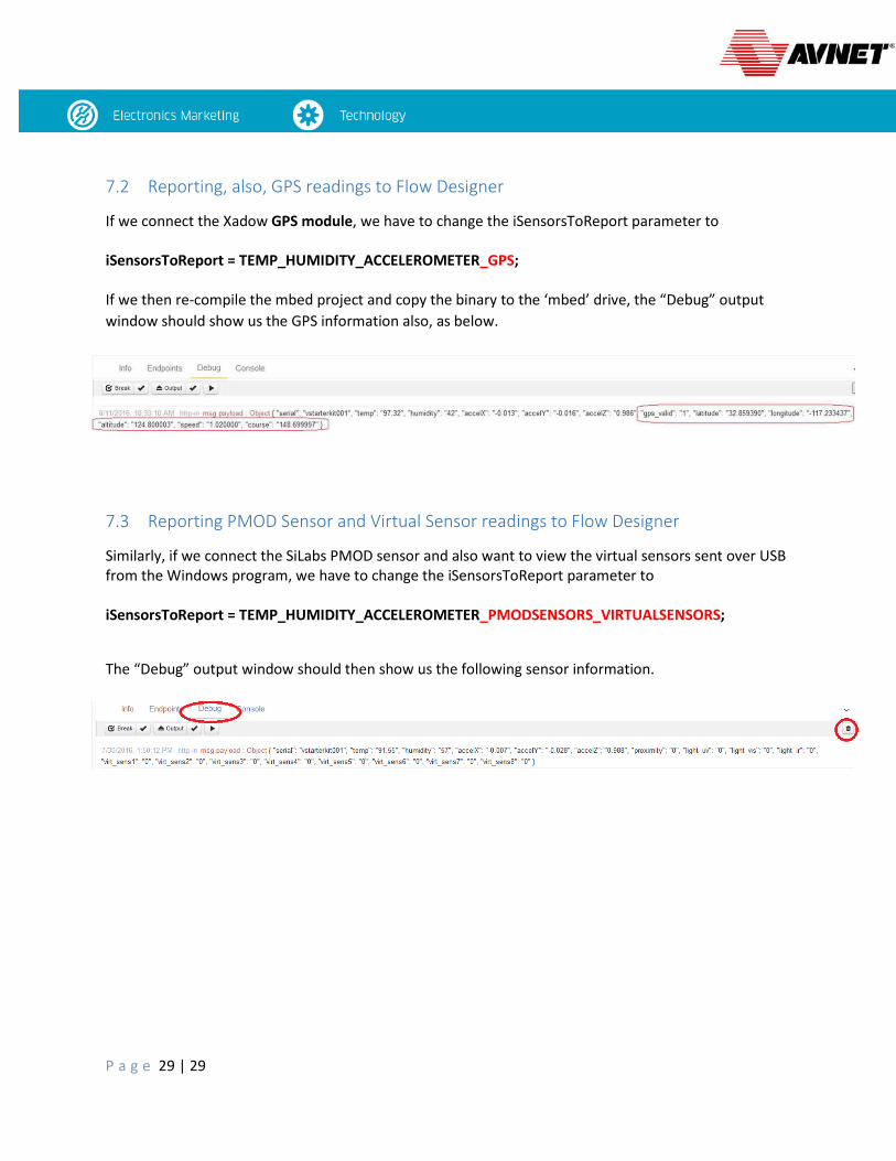
7.2 Reporting, also, GPS readings to Flow Designer
If we connect the Xadow GPS module, we have to change the iSensorsToReport parameter to iSensorsToReport = TEMP_HUMIDITY_ACCELEROMETER_GPS; If we then re-compile the mbed project and copy the binary to the ‘mbed’ drive, the “Debug” output window should show us the GPS information also, as below.
7.3 Reporting PMOD Sensor and Virtual Sensor readings to Flow Designer
Similarly, if we connect the SiLabs PMOD sensor and also want to view the virtual sensors sent over USB from the Windows program, we have to change the iSensorsToReport parameter to iSensorsToReport = TEMP_HUMIDITY_ACCELEROMETER_PMODSENSORS_VIRTUALSENSORS;
The “Debug” output window should then show us the following sensor information.