Embed Size (px)
Citation preview

7/21/2019 AT3W 3 - Earthing
http://slidepdf.com/reader/full/at3w-3-earthing 1/25
EARTHING
7/21/2019 AT3W 3 - Earthing
http://slidepdf.com/reader/full/at3w-3-earthing 2/25EARTHING252
IMPORTANCE OF A SUITABLE EARTHING
A well designed earthing system is basic for any electrical installation to avoid the
danger associated with fault currents, as established in the main earthing standards:
Spain: RBT2002 “Low Voltage Electrotechnical Regulation”. ITC-18 “Earthing systems”.
Great Britain: BS 7430 “Code of practice for Earthing”.
France: NF C 15-100 “Low Voltage Electrical Installations”. Germany: DIN VDE 0100 Part 540 “Earthing arrangements, protective
conductors, equipotential bonding conductors” USA: UL 467 “Grounding and bonding equipment ”.
The resistance should be measured regularly
so it is necessary to place an inspection pit.
The soil humidity will reduce the earthing resistance.
Earthing enhancing compounds
reduce the soil resistivity.
Buried electricity and gas installations
should be known in order to respect the
security distances for each case.
Buried pipes and water tanks should be
known in order to bond them equipotentially
with the earth termination.
In low-conductivity soils, enhanced electrodes, deep electrodes or ring
conductors should be used in order to obtain a suitable earth resistance.
A Low Voltage Earth Termination Systemis aimed:
Other determining factors for designing theEarth Termination System are the following:
To provide security for persons
by limiting the touch voltage.
To protect installations and equipment
by providing a low impedance path.
To improve the quality of the signal
by minimizing the electromagnetic noise.
To x a reference voltage for the
system equipotentialization.
A low Earth Resistance is essential for obtaining an ef ficient Earthing. Conductors
with an accurate section should be used in order to carry the expected current.
Besides, they must be durable against corrosion.
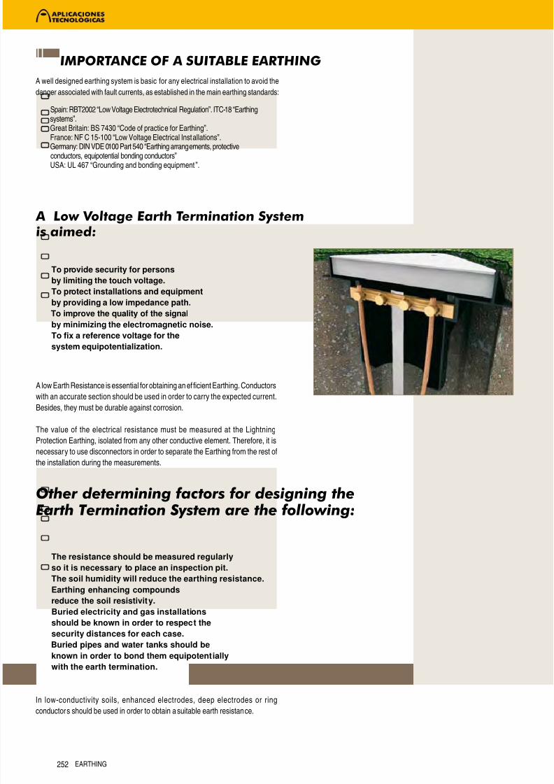
The value of the electrical resistance must be measured at the Lightning
Protection Earthing, isolated from any other conductive element. Therefore, it is
necessary to use disconnectors in order to separate the Earthing from the rest of
the installation during the measurements.

7/21/2019 AT3W 3 - Earthing
http://slidepdf.com/reader/full/at3w-3-earthing 3/25EARTHING 253
Particularly, the Earth Termination System is essential for Lightning Protection,
since the lightning current should disperse there. Each down-conductor must
have an Earth Termination System, formed by conductive elements in contact
with the soil and able to disperse the lightning current in it.
Good earthings of Lightning Protection Systems shall be ableto withstand lightning currents and to disperse them quick andsafely.
In order to accomplish with these requirements, standards set as a first
specification that the resistance of the LPS earthing should be lower than 10Ω.
On another side, it should be noticed that lightning current is an impulse and
therefore it is not advisable to use a single, very long element. The employ of
deep electrodes is interesting if the resistivity is very high at surface but there are
lower layers with much more humidity. Configurations in triangle or “goose-foot”
are suitable for a good lightning current dispersion.
These considerations for improving the impedance should be taken into account
when the earthing is made, since normally the measures are made afterwards
with a conventional Earth Meter which does not register the impedance but
only the earthing resistance, that is, its per formance in case the current were
continuous. A high inductance would not be measured by this type of Earth
Meters and however it is a big obstacle for the current flowing when its waveshape
is, such as lightning, an impulse.
In general it is recommended to bond the Lightning Protection Earth System
with the earthings of the installation in order to avoid surges and dangerous step
voltages.
SPECIFIC CONSIDERATIONS FOR LIGHTNING PROTECTION

7/21/2019 AT3W 3 - Earthing
http://slidepdf.com/reader/full/at3w-3-earthing 4/25EARTHING254254
REGULATIONS
All the earthing materials manufactured by Aplicaciones Tecnológicas comply
with the earthing and lightning protection standards.
The minimum dimensions specified in these standards are the following:
Earthing
Lightningprotection earthing
RBT ITC-18. Earthing systems technical application of Low Voltage
Electrotechnical Regulation.
IEC 62305 / EN 62305 / EN 50164. Protection against lightning.
UNE 21186 / NF C 17-102. Protection of structures, buildings and open-air
zones with Early Streamer Emission air-terminals.
BS 6651. Code of practice for protection of structures against lightning.
NFPA 780. Standard for the installation of lightning protection systems.
BS 7430. Code of practice for Earthing.
NF C 15-100. Low voltage electrical installations.
UL 467. Grounding and bonding equipment.
Type of electrode Material Minimum dimensions
Rod Copperbond steel (250µ) Ø14,2mm
Rod Galvanized steel (78µ) Ø20mm
Solid plate Copper 1000 x 500 x 2mm
Solid plate Galvanized steel (78µ) 1000 x 500 x 3mm
Cable Copper 35mm2
Type of electrode Material Minimum dimensions
Rod Copperbond steel (250µ) Ø14mm
Rod Stainless steel Ø15mm
Rod Copper Ø15mm
Rod Galvanized steel (50µ) Ø16mm
Cross profile rod Galvanized steel (70µ) 50x50x3mm
Tubular rod Copper Øext20mm
Solid plate Copper 500x500x2mm
Solid plate Galvanized steel (70µ) 500x500x3mm
Cable Copper 50mm2
Tape Copper 50mm2 (thickness 2mm)
Tape Stainless steel 100mm2 (thickness 2mm)
Tape Galvanized steel (70µ) 90mm2 (thickness 3mm)
Round Copper Ø8mm
Round Stainless steel Ø10mm
Round Galvanized steel (50µ) Ø10mm
Type of electrode Material Minimum dimensions
Rod Copperbond steel (250µ) 1,2m x Ø14mm
Rod Copper 1,2m x Ø14mm
Rod Stainless steel 1,2m x Ø16mm
Rod Galvanized steel 1,2m x Ø14mm
Tape Copper 25 x 3mm
Round Copper Ø8mm
Cable Copper 50mm2
Type of electrode Material Minimum dimensions
Rod Copperbond steel 2m x Ø15mm
Rod Galvanized steel 2m x Ø25mm
Cable Copper 25mm2
Cable Galvanized steel 95mm2
Type of electrode Material Minimum dimensions
Rod Copperbond steel (250µ) 2,4m x Ø12,7mm
Rod Stainless steel 2,4m x Ø12,7mm
Rod Copper 2,4m x Ø12,7mm
Tubular rod Copper 2,4m x Øext54mm
Type of electrode Material Minimum dimensions
Rod Copperbond steel (250µ) 2m x Ø14mm (*)
Rod Stainless steel 2m x Ø14mm (*)
Rod Galvanized steel (50µ) 2m x Ø19mm (*)
Tubular rod Copper 2m x Øext25mm (*)
Solid plate Copper 500x500x2mm
Cable Copper 50mm2
Stranded tape Copper 30 x 3,5mm
Tape Copper 30 x 2mm
Tape Stainless steel 30 x 2mm
Tape Galvanized steel (50µ) 30 x 3,5mm
Round Copper Ø8mm
Round Stainless steel Ø10mm
Round Galvanized steel (50µ) Ø10mm
Type of electrode Material Minimum dimensions
Rod Copperbond steel (250µ) Ø14mm
Rod Stainless steel Ø12mm
Rod Copper Ø12mm
Rod Galvanized steel Ø14mm
Tape Copper 20 x 2,5mm
Tape Galvanized steel 20 x 2,5mm
Round Copper Ø8mm
Round Galvanized steel Ø8mm
Type of electrode Material Minimum dimensions
Rod Copperbond steel 2,4m x Ø12,7mm
Rod Stainless steel 2,4m x Ø12,7mm
Rod Copper 2,4m x Ø12,7mmRod Galvanized steel 2,4m x Ø12,7mm
Solid plate Copper 600x300x0,8mm
Solid plate Galvanized steel 600x300x0,8mm(*) minimum length according to NF C 17-102: 1m.

7/21/2019 AT3W 3 - Earthing
http://slidepdf.com/reader/full/at3w-3-earthing 5/25
EARTH ELECTRODES, GROUNDENHANCING PRODUCTS ANDEARTH PITS

7/21/2019 AT3W 3 - Earthing
http://slidepdf.com/reader/full/at3w-3-earthing 6/25EARTHING256
ENHANCED ELECTRODES FOR LOW-CONDUCTIVITY SOILS
APLIROD® DYNAMIC ELECTRODE
Reference External size (mm) Shape Included Material Weight (kg)
AT-024H 2000 x Ø28 Vertical AT-020F + AT-031L Copper + Salts 4
AT-025H 2500 x Ø28 Vertical AT-020F + AT-031L Copper + Salts 4,5
AT-012H (1000 + 2000) x Ø54 L-shaped AT-020F + 2 x AT-032L Copper + Salts 62,5
AT-030H (1000 + 3000) x Ø54 L-shaped AT-020F + 2 x AT-032L Copper + Salts 67
AT-032H 2000 (roscado) x Ø54 Vertical AT-020F + 2 x AT-032L Copper + Salts 58,5
AT-033H 3000 (roscado) x Ø54 Vertical AT-020F + 2 x AT-032L Copper + Salts 62,5
AT-102H 2000 x Ø28 Vertical AT-031L Copper + Salts 4
AT-103H 2500 x Ø28 Vertical AT-031L Copper + Salts 4,5
AT-108H (1000 + 2000) x Ø54 L-shaped 2 x AT-032L Copper + Salts 62,5
AT-104H (1000 + 3000) x Ø54 L-shaped 2 x AT-032L Copper + Salts 67
AT-105H 2000 x Ø54 Vertical 2 x AT-032L Copper + Salts 58,5
AT-106H 3000 x Ø54 Vertical 2 x AT-032L Copper + Salts 62,5
AT-035H 190 x Ø220 Charge for APLIROD ® Charge for APLIROD ® Salts 5,5
Meets UL 467, IEC 62305, EN 50164, UNE 21186, NFC 17102
The absence of free ions in the surrounding soil damages the properperformance of the earthing. Dynamic Electrodes are based on the
contribution of ions to the ground.
The system consists mainly of a conductive electrode (APLIROD®) made of
copper and filled with a mixture of ionic compounds. The moisture condenser
absorbs environmental moisture and leaches out at the bottom of the rod,
lowering gradually the resistivity of the surrounding soil:
The efficacy of this earth electrode is improved by placing a ground
conduct ivity improver such as CONDUCTIVER PLUS® (AT-010L) around the
rod.
Soil resistivity and site characteristics are the main factors for determining themodel of electrode to be selected. Poor soil conditions or extremely sensitive
equipment will require longer rods, multiple rods, or a combination of both.
The adequate configuration in most cases is a triangular arrangement.
Vertical shapes are good to obtain low ear th resistance values. L-shaped
models are better when are recommended horizontal configuration of earth
terminations.
INSTRUCTIONS FOR USE
1. For vertical electrodes bore a hole, minimum 20cm diameter and 50cmdeeper than the length of the rod to be buried (AT-025H needs 40mm of
diameter). For the L-Shaped installation, bore a trench suitable to the
electrode dimensions.
2. Withdraw the covers of the leaching holes.
3. Mix the low resistivity compound APLIFILL ® (AT-031l / AT-032l), supplied
together with the electrode, with water outside the excavation and
gradually fill the hole using the proportion of 1 kilo of APLIFILL ® to 8 litres
of water. The mixture fills the perforation up.
4. Place the electrode in the hole so that the upper end is approximately
20cm below the surface. The filling will expand in few minuts.
5. Place the inspection pit so that the cover remains at surface level. The
electrode will stand out approximately 10 cm over the bottom of the
inspection pit, leaving the breathing holes uncovered.
6. WIthdraw the covers of the upper breathing holes.
7. Conect the grounding electrode to the test bonding bar.
8. More electrodes should be places at even intervals, and interconnected
with bare copper, buried at least 0.5m deep. Its is recommended to cover
the conductor with APLIFILL ® .
EARTH ELECTRODES, GROUND ENHANCING PRODUCTS AND EARTH PITS

7/21/2019 AT3W 3 - Earthing
http://slidepdf.com/reader/full/at3w-3-earthing 7/25

7/21/2019 AT3W 3 - Earthing
http://slidepdf.com/reader/full/at3w-3-earthing 8/25EARTHING258
ENHANCED ELECTRODES FOR LOW-CONDUCTIVITY SOILS
GRAPHITE ELECTRODE
Graphite, with its high electrical and thermal conductivity, being unattackable and iner t to chemical agents (apart from oxygen at a high temperature), is a very
good element to make an ear th electrode. The materials used such as perforation filling (graphite powder and thin clay-like powder) assure the contact betweenthe electrode and the ground thanks to the capacity to even penetrate into rocky cracks.
INSTALLATION
This electrode is formed of a rigid graphite core surrounded by a layer of
graphite powder and salts, which whilst helping to avoid mechanical damage
during transportation and installation, also improves the conductivity of the
electrode. This ensemble is introduced into the perforation, which connects
to the test bonding bar installed in the earth pit, using cable of Ø8-10mm ortape of 30×2mm.
In order to optimize its duration and effectiveness, the hole should be filled
with thin clay-like powder and special graphite powder for earthing:
Perforation of Ø200mm
Machinery needed:
Perforator with drill of Ø200mm and 2 meters length.
Mixer (recommended).
Material:
2kg of graphite powder (AT-020L).
6kg of thin clay-like powder (AT-030L).
PROCEDURE:
1. Make a perforation of Ø200mm with a depth of at least 2 meters.
2. Connect to the electrode the necessary length of cable of Ø8-10mm
or tape of 30×2mm to be able to make the connections in the earth pit
afterwards.
3. In an adequate recipient (preferably a mixer), mix the fine clay-like powder
(AT-030L) and the graphite powder (AT-020L) with 60 litres of water.
Note: If a mixer or adequate tool is not available, the filling of the
perforation will be done in batches. For example, the filling can be done
in four batches, using each time approximately 15 litres of water, 1,5kg of
thin clay-like powder and 0,5kg of graphite powder.
4. Empty the mixture into the perforation, making sure it reaches the bottom
of the hole.
5. Install the electrode with the wrapping in the perforation, being careful of
not making strong impacts.
6. Make the necessary connections to the test bonding bar installed in the
earth pit and close.
Hole of 1,5 × 1,5 × 2 meters
Machinery needed:
Retroexcavator.
Material:
2 bags of graphite powder 25kg (AT-020L).
6 bags of thin clay-like powder of 25kg (AT-030L).
Plenty of water.
PROCEDURE:
1. With the retroexcavator make a hole of 1,5 meters of width and 2 meters
of depth.
2. Mix two bags of thin clay-like powder (AT-030L) and enough earth tosufficiently cover approximately 30cm height of the hole. Fill the bottom
of the excavation.
3. Connect to the electrode, the necessary meters of cable of Ø8-10mm or
tape of 30×2mm to be able to make afterwards the connections in the
earth pit.
4. Install the electrode with the wrapping in the perforation, being careful of
not making strong impacts.
5. Cover with water until you reach a level of 10 cm (approximately 225 litres
of water). Wait a few minutes for the filter of the water and the increase in
volume of the thin clay- like powder.
6. Continue filling the hole mixing a bag of thin clay-like powder, half a bag of
graphite powder and enough earth to fill another 30 cm of height. Empty
the mixture into the hole evenly.
7. Repeat steps 5 and 6 until you have used up the thin clay-like powder and
the graphite (3 times).
8. Make the necessary connect ions in the test bonding bar installed in the
earth pit and close.
Reference External size (mm) Shape Included Weight (kg)
AT-070H 600 x Ø150 Rigid graphite core + graphite powder with bag AT-020F 10
AT-073H 1500 x Ø50 Rigid graphite core AT-020F + AT-032L 35
AT-070H AT-070H Application
1 bag of thin clay-like powder 25kg 1/2 bag of graphite powder 25kg Soil
Water
2 bags of
thinclay-like
powder of 25kg
EARTH ELECTRODES, GROUND ENHANCING PRODUCTS AND EARTH PITS

7/21/2019 AT3W 3 - Earthing
http://slidepdf.com/reader/full/at3w-3-earthing 9/25EARTHING 259
AT-003K
AT-002K
AT-072H
AT-041H
AT-041H Application
AT-041H (aplicación tierras)
254µm COPPERBOND EARTH RODS
Aplicaciones Tecnológicas, S.A. has available copperbond earth rods of a
high quality which comply to the most demanding regulations, for efficient and
long lasting earthing. All these electrodes have a covering of electrolytic copper
with a width of 254µm and purity 99,9% which allows a proven resistance tocorrosion. This type of electrolytic covering does not produce cracks or fissures,
which are produced in the exterior layer of the copperclad rods, worsening its
resistance to corrosion.
Numerous regulations specify that on the copperbond earth electrodes the
covering of copper should be at least 250µm. This especially applies to the
regulations on lightning protection systems:
BS 7430: Code of practice of earthing.
UL 467: Grounding and bonding equipment.
Section 250 of National Electrical Code (NEC).
Application technical guide nº 18 of Spanish “Low Voltage Electrotechnical
Regulation”.
IEC 62305-3 (international lightning protection standard).
EN 50164-2 (european lightning protection components standard).
UNE 21186 (spanish lightning protect ion standard).
Using the adequate accessories, threaded copperbond earth rods allow the
extension of the rod to get better earthing resistances.
INSTALLATION
The electrodes should be installed to a depth of at least 50cm.
It is preferable to use various conductors conveniently spread rather than only
one very long earth conductor.
In the case of an earth formed by various interconnected electrodes, it is
recommended that:
The buried rods are in a triangle or line and spaced out with a distance
apart of at least the same as the depth bur ied.
The buried rods are connected by an identical or compatible conductor
to the one used for the down-conductor.
The conductor which joins the rods is buried with a depth of at least 50cm.
Apply the ground enhancing product CONDUCTIVER PLUS ® (AT-010L)
to the buried electrodes in order to obtain a lower earthing resistance.
Couplings of copperbond earth rods
Reference Denomination Nominal size (mm) Material Weight (gr)
AT-002K 5/8" Threaded coupling 70 x Ø19 Aluminium Bronze 80AT-003K 5/8" Threaded driving stud 54 x 22 Stainless steel 80
AT-004K 3/4" Threaded coupling 70 x Ø24 Aluminium Bronze 130
AT-005K 3/4" Threaded driving stud 54 x 25 Stainless steel 130
Reference Nominal size (mm) Shank diameter (mm) Shape Weight (kg)
AT-076H 1200 x Ø16 14,23 Two threads 5/8" 1,5
AT-077H 1500 x Ø16 14,23 Two threads 5/8" 1,9
AT-078H 1800 x Ø16 14,23 Two threads 5/8" 2,28
AT-041H 2000 x Ø16 14,23 Two threads 5/8" 2,53
AT-016H 2400 x Ø16 14,23 Two threads 5/8" 3
AT-098H 3000 x Ø16 14,23 Two threads 5/8" 3,8
AT-069H 1200 x Ø14,23 14,23 No thread 1,5AT-071H 1500 x Ø14,23 14,23 No thread 1,9
AT-053H 1800 x Ø14,23 14,23 No thread 2,28
AT-072H 2000 x Ø14,23 14,23 No thread 2,53
AT-026H 2400 x Ø14,23 14,23 No thread 3
AT-043H 3000 x Ø14,23 14,23 No thread 3,8
AT-086H 1200 x Ø19 17,28 Two threads 3/4" 2,15
AT-087H 1500 x Ø19 17,28 Two threads 3/4" 2,75
AT-017H 1800 x Ø19 17,28 Two threads 3/4" 3,27
AT-042H 2000 x Ø19 17,28 Two threads 3/4" 3,62
AT-018H 2400 x Ø19 17,28 Two threads 3/4" 4,35
AT-019H 3000 x Ø19 17,28 Two threads 3/4" 5,44
AT-079H 1200 x Ø17,28 17,28 No thread 2,15
AT-081H 1500 x Ø17,28 17,28 No thread 2,75
AT-027H 1800 x Ø17,28 17,28 No thread 3,27
AT-082H 2000 x Ø17,28 17,28 No thread 3,62
AT-028H 2400 x Ø17,28 17,28 No thread 4,35
AT-029H 3000 x Ø17,28 17,28 No thread 5,44
Meets BS 7430, UL 467, IEC 62305, EN 50164, NFPA 780, UNE 21186, NFC 17102
Other copper thickness as 100µm and 300µm are available on request.
d≥L
L
L50 cm
Ld≥L
EARTH ELECTRODES, GROUND ENHANCING PRODUCTS AND EARTH PITS

7/21/2019 AT3W 3 - Earthing
http://slidepdf.com/reader/full/at3w-3-earthing 10/25EARTHING260
SOLID COPPER EARTH RODS
STAINLESS STEEL EARTH RODS
Solid copper and stainless steel rods allow a long lasting earth in grounds with high corrosion level. Threaded electrodes with the correct accessories allow
the length to be increased, thus achieving a better resistance.
AT-031H
AT-006K
AT-007K AT-008K
AT-080H
AT-038H
AT-031H application
Reference Nominal size (mm) Shape Weight (kg)
AT-031H 1200 x Ø15 Internal 5/8" thread 1,63
AT-036H 1200 x Ø20 Internal 3/4" thread 3,35
Reference Nominal size (mm) Shape Weight (kg)
AT-000H 1500 x Ø10 No thread 1,5
AT-099H 1000 x Ø16 No thread 1,6
AT-100H 1500 x Ø16 No thread 2,2
AT-080H 2000 x Ø16 No thread 3,33
AT-038H 1500 x Ø20 Extensible type AZ 3,75
AT-037H 1200 x Ø16 Internal 5/8" threads 1,65
Couplings of solid copper and stainless steel earth rods
Reference Denomination Nominal size (mm) Material Weight (kg)
AT-006K 15/16mm Driving stud 39 x Ø14 Stainless steel 40
AT-007K 15/16mm Spike 42 x Ø14 Stainless steel 40
AT-008K Coupling dowel 40 x Ø10 Stainless steel 20
AT-009K 20mm Driving stud 42 x Ø19 Stainless steel 60
AT-042K 20mm Spike 55 x Ø19 Stainless steel 80
Meets BS 7430, UL 467, IEC 62305, EN 50164, NFPA 780, UNE 21186, NFC 17102
Meets BS 7430, UL 467, IEC 62305, EN 50164, NFPA 780, UNE 21186, NFC 17102
Meets EN 50164
AT-038H application
EARTH ELECTRODES, GROUND ENHANCING PRODUCTS AND EARTH PITS

7/21/2019 AT3W 3 - Earthing
http://slidepdf.com/reader/full/at3w-3-earthing 11/25EARTHING 261
Galvanized steel rods are a good option to obtain low resistances in unaggresive grounds. There are extendable models to reach longer lengths and achieve
better earth resistances.
AT-045H
AT-003H
AT-037K
AT-046H
AT-095H
AT-000K
AT-003H application
GALVANIZED STEEL EARTH RODS
GOOSE FOOT
Reference Nominal size (mm) Shape Weight (kg)
AT-039H 1000 x Ø16 No thread 1,65
AT-044H 1500 x Ø16 No thread 2,53
AT-045H 2000 x Ø16 No thread 3,42
AT-046H 1500 x Ø20 Extensible type Z 3,71
AT-003H 1500 x Ø20 Extensible type S 3,71
AT-047H 1500 x Ø25 Extensible type Z 5,62
AT-049H 1500 x Ø25 Extensible type S 5,62
AT-093H 1000 x 50 x 50 x 5 X-shaped profile 3,9
AT-094H 1500 x 50 x 50 x 5 X-shaped profile 5,85
AT-095H 2000 x 50 x 50 x 5 X-shaped profile 7,81AT-096H 2500 x 50 x 50 x 5 X-shaped profile 9,75
AT-097H 3000 x 50 x 50 x 5 X-shaped profile 11,75
Reference Nominal size Material Weight (kg)
AT-000K 30 x 2 mm (4 m + 3 x 7m) Tin-plated Copper Tape 13
AT-001K 30 x 2 mm (1 m + 3 x 3m) Tin-plated Copper Tape 5
Couplings of galvanized steel earth rods
Reference Denomination Nominal size (mm) Material Weight (kg)
AT-037K Impact tip for earth rods Ø20mm 40 x Ø20 Galvanized steel 50
AT-038K Impact tip for earth rods Ø25mm 45 x Ø25 Galvanized steel 70
Meets DIN 48-452
Meets EN 50164
Meets UNE 21186, NFC 17102
The duck foot is a configuration that the regulation of Lightning Protection UNE 21186 and NFC 17102 recommends in
order to obtain low earth inductances. It is formed with tin-plated copper tape of 30x2mm.
Installation:
Make ditches of at least half a meter depth.
Extend the tape and cut the corresponding lengths.
Unscrew the clamp and introduce the stretches of tape as indicated in the drawing with an angle of 45º.
Firmly fix the screws of the clamp.
AT-095H application
EARTH ELECTRODES, GROUND ENHANCING PRODUCTS AND EARTH PITS

7/21/2019 AT3W 3 - Earthing
http://slidepdf.com/reader/full/at3w-3-earthing 12/25EARTHING262
EARTH PLATES
COPPER LATTICES AND GRIDS
AT-116H (Cu)
AT-122H (GS)
AT-070J AT-126H
The use of earth plates as electrodes reduces the resistance of earthing in stony grounds, as it increases the area of contact between the electrode and the
ground.
The references AT-116H and AT-122H comply with the minimum dimensions recommended in the nº18 Technical Application Guide “Ear thing installations” of
the 2002 Low Voltage Spanish Electrotechnical Regulation.
Reference Nominal size (mm) Included Material Weight (kg)
AT-050J 500 x 500 x 2 AT-020F Copper 4
AT-116H 1000 x 500 x 2 AT-020F Copper 8
AT-117H 600 x 600 x 1,5 - Copper 5
AT-118H 600 x 600 x 3 - Copper 10
AT-119H 900 x 900 x 1,5 - Copper 11
AT-120H 900 x 900 x 3 - Copper 22
AT-121H 500 x 500 x 3 - Galvanized steel 4
AT-122H 1000 x 500 x 3 - Galvanized steel 8
Meets IEC 62305, EN 50164, EN 13601, BS 2874, UNE 21186, NFC 17102, NFPA 780
Meets IEC 62305, EN 50164, EN 13601
Reference Nominal size (mm) Grids Weight (kg)
AT-128H 1000 x 1000 x 2 115 x 55 mm 3
AT-123H 2000 x 1000 x 2 115 x 55 mm 4
AT-070J 3000 x 1000 x 2 115 x 55 mm 5AT-126H 600 x 600 x 3 120 x 120 mm 4
AT-125H 900 x 900 x 3 190 x 190 mm 7,3
Mesh earths are a more economical option than earth plates and still work well in stony ground, reducing the contact voltages that may occur. AT-070J is
recommended to avoid step voltages in public buildings with low resistivity soil.
EARTH ELECTRODES, GROUND ENHANCING PRODUCTS AND EARTH PITS

7/21/2019 AT3W 3 - Earthing
http://slidepdf.com/reader/full/at3w-3-earthing 13/25EARTHING 263
AT-010L AT-032L
Meets EN 50164, UNE 21186, NFC 17102
CONDUCTIVER PLUS is a non corrosive ground enhancing gel with low solubility but is very hygroscopic. It is made of an electrolyte base, which
contributes to the conductiv ity of the mixture.
The conductivity of the ground is almost exclusively of an electrolytic nature due to the salts dispersed in the water which impregnate it and which concentrate
on the surface due to an adhesive phenomenon of the sand grains and clay in the ground.Therefore, it is possible to increase the conductivity of the ground, improving its absorption power, retention of water and increasing its richness in soluble salts.
It would be very easy to achieve this effect using a simple method, impregnating it with any electrolyte, such as common salt (NaCl) or sodium carbonate
(Na2CO3), but the high solubility of these salts, as well as their low absorption in the ground mean that they are very quickly swept away by the infiltration waters,
making their action very short term. Another inconvenience of common salt is its corrosive effects on the earthing electrodes.
The components of the CONDUCTIVER PLUS ® gel have been selected according to their solubility, in order to obtain from the soluble components, a low
soluble product, which will provide us with a long lasting conductor product deposit. The main advantage of this product is that a conductor gel is formed
below the soil near the electrode.
In summary, the CONDUCTIVER PLUS ® gel is characterised by:
Having the capacity to create partially ionized electrolytes, with a high charge and a high capacity to retain water and to form gels.
Remaining in the ground for a long time, thanks to the formation of links with the particles.
Increasing conductivity (approximately 200%) of the ground during one year and rainfall of 700 litres/m2.
Not causing corrosion of the earth electrodes.
Being totally ecological.
METHOD OF APPLICATION
1. The ground can be dry, no previous preparation is necessary.
2. Prepare a mixture of the YELLOW product in 5 litres of water using the measuring recipient.
3. Empty the first solution to the ground and add another 5 litres of water.
4. Leave the product to disappear into the ground.
5. Clean the recipient before continuing with the next product.
6. Prepare a second solution with the WHITE product and 5 litres of water. Empty this mixture evenly on the ground. Add another 5 litres of water. Leave to
filter until complete absorption.
7. Once the second product has filtered, you can then take the earth resistance measurement.
Reference Denomination Description Weight (kg)
AT-010L CONDUCTIVER PLUS ® Non-corrosive and ecological gel that improves soil conductivity 4,5
AT-020L Graphite powder Backfill specific for earth termination systems 25
AT-030L Thin clay-like powder Backfill specific for earth termination systems 25
AT-031L APLIFILL ® Compound that reduces soil resistivity by retaining moisture 1
AT-032L APLIFILL ® Compound that reduces soil resistivity by retaining moisture 25
GROUND ENHANCING PRODUCTS
EARTH ELECTRODES, GROUND ENHANCING PRODUCTS AND EARTH PITS

7/21/2019 AT3W 3 - Earthing
http://slidepdf.com/reader/full/at3w-3-earthing 14/25EARTHING264
JOINT PROTECTION
EARTH PITS
AT-000J
AT-010J
AT-010K
AT-012K
AT-010H
Strips to protect buried joints from corrosion.
Aplicaciones Tecnológicas earth pits cover all industrial and commercial applications as they are
available in 3 materials: polypropylene, concrete and cast iron. AT-010H can withstand loads of 5.000
kg. The principle advantages of these earth pits are the following:
- Easily storage.
- Good resistance to chemical substances.
- Resistant to UV rays.
Reference Nominal size Material Weight (kg)
AT-000J 20 mm x 10 m roll Self-vulcanising strip 180
AT-010J 50 mm x 10 m roll Denso tape (Bituminous strip) 610
Reference Nominal size (mm) Material Weight (kg)
AT-010H 250 x 250 x 250 Polypropylene 1,5
AT-010K 410 x 410 x 300 Concrete 60
AT-012K 245 x 245 x 115 Iron cast 31
Meets EN 50164, UNE 21186, NFC 17102
EARTH ELECTRODES, GROUND ENHANCING PRODUCTS AND EARTH PITS

7/21/2019 AT3W 3 - Earthing
http://slidepdf.com/reader/full/at3w-3-earthing 15/25
EQUIPOTENTIAL BONDING

7/21/2019 AT3W 3 - Earthing
http://slidepdf.com/reader/full/at3w-3-earthing 16/25EARTHING266
BONDING BARS FOR EARTH PITS
EQUIPOTENTIAL BONDING BAR
AT-020H application
AT-020H (NB) AT-021J (SS)
AT-050F
AT-020H and AT-021J allow to disconnect the down-conductor of a lightning protection system from the ear th electrode, to be ab le to measure the earth
resistance adequately. They are ready to be fixed to the earth pit AT-010H. You can fix up to 4 copper cables or rounds and 3 tapes.
AT-051F allows joints up to 7 copper cables or round conductors. This bar can be fixed to the earth pit AT-011K. The fixation holes at the end of the bar are
separated by 264mm and have a diameter of 16mm.
Equipotential bar which allows the jointing of various conductors (cable, tape, round). The fixation holes at the end of the bar are separated 164 x 35mm and
have a diameter of 8,5mm.
Reference Nominal size (mm)Conductor range
MaterialWeight
(kg)Round Tape
AT-050F 190 x 52 x 427 x (2,5 - 25 mm2) /
1 x (Ø 6 - 11 mm) (25 - 70 mm2)30 x 2 mm - 30 x 3,5 mm Tin-plated copper (contact bar) 200
Reference Nominal size (mm)Conductor range
MaterialWeight
(kg)Round Tape
AT-020H 235 x 40 x 25 4 x (Ø 8 - 10 mm) (50 - 70 mm2) 3 x (30 x 2 mm - 30 x 3,5 mm) Naval brass 0,5
AT-021J 235 x 40 x 25 4 x (Ø 8 - 10 mm) (50 - 70 mm2) 3 x (30 x 2 mm - 30 x 3,5 mm) Stainless steel 0,5
AT-051F 325 x 70 x 6 7 x (Ø 8 - 10 mm) (50 - 70 mm2) - Copper 1,5
Meets EN 50164, UNE 21186, NFC 17102
Meets BS 2874
AT-051F
AT-051F application
AT-050F application
EQUIPOTENTIAL BONDING

7/21/2019 AT3W 3 - Earthing
http://slidepdf.com/reader/full/at3w-3-earthing 17/25EARTHING 267
AT-055J
AT-056J AT-057J AT-054J application
EARTH BARS
Equipotential bars which allow the jointing of various copper cables or round conductors with tin plated copper compression terminals (for instance AT-021K).
Reference Denomination Nominalsize (mm)
Conductor
range Material Weight(kg)
Round Tape
AT-053J Insulator 51 x Ø36 M10 bolt - Polyester 0,12
AT-054J Earth bar 6 way 400 x 90 x 90 M10 bolt - Copper 1,8
AT-116J Earth bar 6 way 400 x 90 x 90 M10 bolt - Stainless steel 1
AT-055J Earth bar 6 way with single disconnecting link 475 x 90 x 96 M10 bolt - Copper 2.3
AT-056J Earth bar 6 way with twin disconnecting links 550 x 90 x 96 M10 bolt - Copper 2,8
AT-057J Disconnecting link 125 x 90 x 90 M10 bolt - Copper 0,6
AT-058J Earth bar 8 way 500 x 90 x 90 M10 bolt - Copper 2,2
AT-117J Earth bar 8 way 500 x 90 x 90 M10 bolt - Stainless steel 1,2
AT-020J Earth bar 8 way with single disconnecting link 575 x 90 x 96 M10 bolt - Copper 2,7
AT-079J Earth bar 8 way with twin disconnecting links 650 x 90 x 96 M10 bolt - Copper 3,2AT-090J Earth bar 10 way 650 x 90 x 90 M10 bolt - Copper 2,8
AT-118J Earth bar 10 way 650 x 90 x 90 M10 bolt - Stainless steel 1,4
AT-062J Earth bar 10 way with single disconnecting link 725 x 90 x 96 M10 bolt - Copper 3,3
AT-063J Earth bar 10 way with twin disconnecting links 800 x 90 x 96 M10 bolt - Copper 3,8
AT-064J Earth bar 12 way 750 x 90 x 90 M10 bolt - Copper 3,2
AT-119J Earth bar 12 way 750 x 90 x 90 M10 bolt - Stainless steel 1,6
AT-065J Earth bar 12 way with single disconnecting link 825 x 90 x 96 M10 bolt - Copper 3,7
AT-066J Earth bar 12 way with twin disconnecting links 900 x 90 x 96 M10 bolt - Copper 4,2
AT-067J Earth bar 14 way 850 x 90 x 90 M10 bolt - Copper 3,6
AT-068J Earth bar 14 way with single disconnecting link 925 x 90 x 96 M10 bolt - Copper 4,1
AT-069J Earth bar 14 way with twin disconnecting links 1000 x 90 x 96 M10 bolt - Copper 4,6AT-059J Earth bar 16 way 950 x 90 x 90 M10 bolt - Copper 4
AT-071J Earth bar 16 way with single disconnecting link 1025 x 90 x 96 M10 bolt - Copper 4,5
AT-072J Earth bar 16 way with twin disconnecting links 1100 x 90 x 96 M10 bolt - Copper 5
AT-073J Earth bar 18 way 1050 x 90 x 90 M10 bolt - Copper 4,4
AT-074J Earth bar 18 way with single disconnecting link 1125 x 90 x 96 M10 bolt - Copper 4,9
AT-075J Earth bar 18 way with twin disconnecting links 1200 x 90 x 96 M10 bolt - Copper 5,4
AT-076J Earth bar 20 way 1200 x 90 x 90 M10 bolt - Copper 5
AT-077J Earth bar 20 way with single disconnecting link 1275 x 90 x 96 M10 bolt - Copper 5,5
AT-078J Earth bar 20 way with twin disconnecting links 1350 x 90 x 96 M10 bolt - Copper 6
Meets BS 2874
AT-053J
AT-054J (Cu)
AT-116J (SS)
EQUIPOTENTIAL BONDING

7/21/2019 AT3W 3 - Earthing
http://slidepdf.com/reader/full/at3w-3-earthing 18/25EARTHING268
EARTH POINTS
AT-096J
AT-097J
AT-100J
AT-102J
AT-120J
AT-036K
AT-098J
AT-100J application
Equipotential earth points which are fixed to the structure to provide joints to earthing conductors.
Reference Denomination Nominal size (mm) Material Weight (gr)
AT-096J 1 hole (M8 x 15 mm) 80 x Ø33 Gunmetal 140
AT-097J 2 holes (M8 x 12 mm) 80 x 63 x 63 Gunmetal 280
AT-098J 4 holes (M8 x 14 mm) 80 x 63 x 63 Gunmetal 410
AT-099J 1 hole (M8 x 15 mm) with 500mm tail of 70 mm2 80 x Ø33 Gunmetal / PVC covered copper 560
AT-100J 2 holes (M8 x 12 mm) with 500mm tail of 70 mm2 80 x 63 x 63 Gunmetal / PVC covered copper 840
AT-101J 4 holes (M8 x 14 mm) with 500mm tail of 70 mm2 80 x 63 x 63 Gunmetal / PVC covered copper 1140
Meets EN 50164
EARTH BOSS
FIXED EARTHING TERMINAL
DISTANCE HOLDER
Earth point to weld to a metallic structure.
Reference Nominal size Material Weight (gr)
AT-102J M10 x 50 x 50 mm Mild steel 800
Reference Nominal size Material Weight (gr)
AT-120J M10 x Ø80 x 200 mm Stainless steel 300
Terminal which is fixed to the structure to provide accessible ear th point.
Allows the use of galvanized steel tape as a ground conductor at foundation level.
ReferenceNominal
size (mm)
Conductor rangeMaterial
Weight
(gr)Round Tape
AT-036K 280 x 35 x 8 Ø 8 - 10 mm / 50 - 70 mm2 30 x 2 mm - 40 x 3,5 mm Galvanized steel 80
EQUIPOTENTIAL BONDING

7/21/2019 AT3W 3 - Earthing
http://slidepdf.com/reader/full/at3w-3-earthing 19/25EARTHING 269
AT-050K AT-050K application
SUPPORT FOR TAPE CONDUCTORS
SPARK GAP FOR EARTH BONDING
Allows the formation of an equipotential ring using tape conductor.
Reference Nominal size (mm)
Conductor range
MaterialWeight
(gr)Round Tape
AT-033K 60 x 36 x 27 - 30 x 2 mm - 50 x 6 mm Copper 120
AT-034K 60 x 36 x 27 - 30 x 2 mm - 50 x 6 mm Galvanized steel 120
AT-035K 60 x 36 x 27 - 30 x 2 mm - 50 x 6 mm Stainless steel 120
AT-039K 70 x 40 x 27 - 30 x 2 mm - 50 x 11 mm Copper 120
AT-040K 70 x 40 x 27 - 30 x 2 mm - 50 x 11 mm Galvanized steel 120
AT-041K 70 x 40 x 27 - 30 x 2 mm - 50 x 11 mm Stainless steel 120
Reference Nominal s ize (mm)Conductor range
MaterialWeight
(kg)Round Tape
AT-050K 216 x 57 x 38 Ø 8 - 10 mm (50 - 70 mm2) 3 x (30 x 2 mm - 30 x 3,5 mm) Naval brass (contact) 1
AT-040K (GS)
AT-039K (Cu)
AT-041K (SS)
In the lightning protection regulations it is recommended to join all earths,
including both electrical and lightning protection. In this way we avoid serious
problems of resistive earth couplings.
However, on some occasions this connection can not be made, for example,
because it would cause corrosion problems. In these cases the AT-050K is the
most appropriate means of making the earthing connections.
In normal conditions, this protector keeps the earths isolated, thus avoiding
corrosion problems. When a discharge occurs and the voltage increases in
the earths, the spark gap will activate, directly joining the earths and thus
preventing the passage of current from one to another through equipment and
internal installations.
INSTALLATION
For its installation, the protector has two joints AT-020F. It is recommended to
make the installation in a specific earth pit.
EQUIPOTENTIAL BONDING

7/21/2019 AT3W 3 - Earthing
http://slidepdf.com/reader/full/at3w-3-earthing 20/25

7/21/2019 AT3W 3 - Earthing
http://slidepdf.com/reader/full/at3w-3-earthing 21/25
EARTH CLAMPING

7/21/2019 AT3W 3 - Earthing
http://slidepdf.com/reader/full/at3w-3-earthing 22/25EARTHING272
MULTIPURPOSE CLAMP
ROD TO TAPE A CLAMP
ROD TO CABLE G CLAMP
Earth clamp for connection between copper cable, round or tape conductors to copper or copperbond earth rod.
Earth clamp for connection between copper tape and copper or copperbond earth rod.
Earth clamp for connection between cable or round conductor and copper or copperbond earth rod.
AT-090H
(application with cable)
Reference Nominal size (mm)Range
MaterialWeight
(gr)Earth Rod Tape
AT-080J 51 x 36 x 18 Ø 12 - 20 mm 25 x 3 mm - 26 x 12 mm Gunmetal 150
AT-081J 44 x 51 x 22 Ø 16 - 20 mm 30 x 2 mm - 40 x 12 mm Gunmetal 240
AT-082J 47 x 69 x 21 Ø 16 - 20 mm 50 x 6 mm - 51 x 12 mm Gunmetal 300
Reference Nominal size (mm)
Range
MaterialWeight
(gr)Earth Rod Round / Tape
AT-090H 52 x 41 x 30 Ø 14 - 19 mm Ø 8 - 10 mm (50 - 70 mm2) / 30 x 2 mm - 30 x 3,5 mm Naval brass 240
AT-083J application
AT-080J application
Reference Nominal size (mm)Range
MaterialWeight
(gr)Earth Rod Round
AT-083J 41 x 21 x 18 Ø 16 mm 16 - 50 mm2 Gunmetal 60
AT-112J 41 x 21 x 18 Ø 16 mm 16 - 70 mm2 Galvanized steel 60
AT-086J 48 x 30 x 19 Ø 20 mm 35 - 95 mm2 Gunmetal 60 AT-083J (Gu)
AT-112J (GS)
Meets EN 50164, UNE 21186, NFC 17102
Meets EN 50164, BS 1400
Meets EN 50164, BS 2874, BS 1400
AT-080J
AT-090H
(application with tape)
EARTH CLAMPING

7/21/2019 AT3W 3 - Earthing
http://slidepdf.com/reader/full/at3w-3-earthing 23/25EARTHING 273
Earth clamp for connection between copper tape and earth rod or metal reinforcing bar.
Earth clamp for connection between copper cable or round conductor and ear th rod or metal reinforced bar.
AT-087J
AT-094J
AT-087J application
AT-093J application
Reference
Range
Material Weight (gr)Earth Rod Tape
AT-087J Ø 16 mm 25 x 3 mm Gunmetal 260
AT-088J Ø 20 mm 25 x 3 mm Gunmetal 260
ReferenceRange
Material Weight (gr)Earth Rod Round
AT-089J Ø 14 – 20 mm 2 x (50 - 120 mm2) Naval brass 250
AT-094J Ø 16 – 20 mm 35 - 70 mm2 Gunmetal 390
AT-091J Ø 16 – 20 mm 70 - 185 mm2 Gunmetal 390
AT-092J Ø 16 – 20 mm 150 - 300 mm2 Gunmetal 620
ReferenceNominal
size (mm)
RangeMaterial
Weight(gr)Earth Rod Round
AT-093J 52 x 26 x 25 Ø 16 mm Tornillo M10 Gunmetal 300
AT-095J 50 x 29 x 28 Ø 20 mm Tornillo M10 Gunmetal 300
U-BOLT ROD E CLAMP
ROD TO CABLE CGUV CLAMP
Meets EN 50164, BS 1400
Meets EN 50164, UNE 21186, NFC 17102, BS 1400
ROD TO CABLE LUG B CLAMP
AT-089J
AT-093J
Earth clamp for connection between copper cable with copper compression terminal (for instance AT-021K) and copper or copperbond earth rod.
Meets EN 50164, BS 2874, BS 1400
EARTH CLAMPING

7/21/2019 AT3W 3 - Earthing
http://slidepdf.com/reader/full/at3w-3-earthing 24/25EARTHING274
DISCONNECTING SLEEVE
UNI DISCONNECTING CLAMP FOR CABLE
UNIVERSAL CLAMP
Lineal earth clamp for connection between galvanized steel round conductor and galvanized steel earth rod.
AT-135J
ReferenceNominal
size (mm)
Range
MaterialWeight
(gr)Earth Rod Round
AT-135J 43 x 41 x 30 Ø 16 mm Ø 7 - 10 mm (35 - 70 mm2) Galvanized steel 120
ReferenceNominal
size (mm)
RangeMaterial
Weight
(gr)Earth Rod RoundAT-025F 48 x 44 x 20 Ø 16 mm Ø 8 - 10 mm (50 - 70 mm2) Stainless steel 130
AT-126J 48 x 44 x 20 Ø 15 - 25 mm Ø 8 - 10 mm (50 - 70 mm2) Galvanized steel 460
AT-127J 48 x 44 x 20 Ø 16 mm Ø 8 - 10 mm (50 - 70 mm2) Copper 130
AT-128J 48 x 44 x 20 Ø 16 mm Ø 8 - 10 mm (50 - 70 mm2) Galvanized steel 130
Reference Nominalsize (mm)
Range Material Weight(gr)Earth Rod Round
AT-113J 58 x 30 x 20Ø 16 mm
(Galvanized steel)Ø 8 - 10 mm
(50 - 70 mm2) (Copper)Bimetallic 150
AT-114J 58 x 30 x 20 Ø 16 mm Ø 8 - 10 mm (50 - 70 mm2) Galvanized steel 150
AT-115J 58 x 30 x 20 Ø 16 mm Ø 8 - 10 mm (50 - 70 mm2) Stainless steel 100
Earth clamp for connection between cable or round conductor and galvanized steel or stainless steel earth rod.
AT-114J (GS)
AT-115J (SS)
AT-113J (GS/Cu)
L-shape earth clamp for connection between cable or round conductor to earth rod.
AT-025F (SS)
AT-127J (Cu)
AT-128J (GS)
AT-025F application
AT-114J application
EARTH CLAMPING

7/21/2019 AT3W 3 - Earthing
http://slidepdf.com/reader/full/at3w-3-earthing 25/25
Reference Nominal size (mm)
Range
Material Weight (gr)Earth Rod Round
AT-136J 60 x 60 x 22 Ø 16 mm Ø 8 - 10 mm (50 - 70 mm2) Galvanized steel 330
AT-137J 60 x 60 x 22 Ø 16 mm Ø 8 - 10 mm (50 - 70 mm2) Stainless steel 330
AT-138J 60 x 60 x 22 Ø 16 mm Ø 8 - 10 mm (50 - 70 mm2) Copper 330
ReferenceNominal
size (mm)
RangeMaterial
Weight(gr)
Earth Rod Round / TapeAT-129J 108 x 30 x 22 Ø 20 mm Ø 8 - 10 mm (50 - 70 mm2) / 30 x 2 mm - 30 x 3,5 mm Galvanized steel 370
AT-130J 108 x 30 x 18 Ø 16 mm Ø 8 - 10 mm (50 - 70 mm2) / 30 x 2 mm - 30 x 3,5 mm Galvanized steel 370
AT-131J 108 x 30 x 27 Ø 25 mm Ø 8 - 10 mm (50 - 70 mm2) / 30 x 2 mm - 30 x 3,5 mm Galvanized steel 370
AT-132J 108 x 30 x 22 Ø 20 mm Ø 8 - 10 mm (50 - 70 mm2) / 30 x 2 mm - 30 x 3,5 mm Stainless steel 370
AT-133J 108 x 30 x 18 Ø 16 mm Ø 8 - 10 mm (50 - 70 mm2) / 30 x 2 mm - 30 x 3,5 mm Stainless steel 370
AT-134J 108 x 30 x 27 Ø 25 mm Ø 8 - 10 mm (50 - 70 mm2) / 30 x 2 mm - 30 x 3,5 mm Stainless steel 370
AT-130J application
T, L CLAMP
Cross-shape earth clamp for connection between cable or round conductor to earth rod.
CONNECTING CLAMP
AT-136J (GS)
AT-137J (SS)
AT-138J (Cu)
Cross-shaped earth clamp for connection between cable, tape or round conductor to earth rod.
AT-130J (GS)
AT-133J (SS)
EARTH CLAMPING