Embed Size (px)
Citation preview
"AT" SERIES ELECTRIC HOT WATER BOILERSFOR FORCED HOT WATER
ARGO TECHNOLOGY, INC.554 Berlin TurnpikeBerlin, CT 06037Phone: (860) 828-6513Fax: (860) 828-3856www.argoindustries.comIN
STA
LLAT
ION
MA
NU
AL
AN
D O
PER
ATIN
G IN
STR
UC
TIO
NS
P/N I-80, Rev. 3.1 [08/04]
An ISO 9001-2000 Certified Company
2
! !
! !
! !
INSTALLATION MANUAL AND OPERATING INSTRUCTIONS
P/N# I-80, Rev. 1.0 [05/04] • Printed in USA • Made In USA
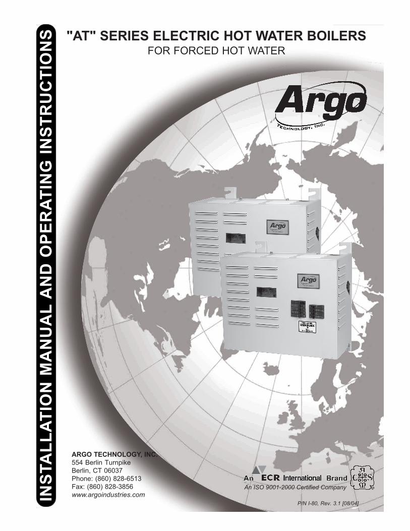
TABLE OF CONTENTS
Safety Symbols .................................................... 2Warnings .............................................................. 3Introduction .......................................................... 3Product Description .............................................. 3Voltage Rating Tables .......................................... 4Installation Procedure .......................................... 5Design of Water Circulating System .................... 6Connecting Supply and Return Piping ................. 6Connecting Electrical Power Supply .................... 8Wiring Diagrams ................................................ 11Thermostat Installation ....................................... 15Startup and Seasonal Maintenence ................... 15Troubleshooting ................................................. 16Maintenance ....................................................... 17Parts List - 2 Element Electric Boilers ................ 18Parts List - 4 Element Electric Boilers ................ 19Additional Wiring Diagrams ............................... 20Modular Boiler Piping ......................................... 23Troubleshooting ................................................. 24"AT" Series Boiler Dimensions ........................... 27Homeowner's Reference Table.......................... 28
KEEP THIS MANUAL NEAR BOILERRETAIN FOR FUTURE REFERENCE
SAFETY SYMBOLS
The following defined symbols are used throughoutthis manual to notify the reader of potential hazardsof varying risk levels.
DANGER
Indicates an imminently hazardous situationwhich, if not avoided, WILL result in death orserious injury.
WARNING
Indicates a potentially hazardous situationwhich, if not avoided, COULD result in deathor serious injury.
CAUTION
Indicates a potential hazardous situationwhich, if not avoided, MAY result in minor ormoderate injury. It may also be used to alertagainst unsafe practices.
IMPORTANT: Read the following instructionsCOMPLETELY before installing!!
16027 Tested For 30 LBS.ASME
Working Pressure
3
! !
! !
Electrical Energy x Conversion Factor = Heat Energy -or-
Kilowatts Of Electricity Used Per Hour x 3412 = British Thermal Units (BTUs) Available Per Hour For Heating
WARNINGS
WARNING
1. BOILER SIZING IS CRUCIAL. The maximumhourly heat loss for each heated space shouldbe calculated in accordance with the proce-dures describes in The Hydronics Institute(I=B=R) manual H-22 (Heat Loss CalculationGuide), or by any other method which is suit-able for local conditions, provided the resultsare in substantial agreement. Select the ap-propriate boiler based on accurate heat losscalculation. DO NOT OVERSIZE THE BOILER,AS SIZING IS CRITICAL FOR IN-FLOOR RADI-ANT HEAT APPLICATIONS.
2. Keep boiler area clear and free from com-bustible materials, gasoline and other flam-mable vapors and liquids.
3. DO NOT obstruct air openings to the boilerroom.
4. Modification, substitution or elimination offactory equipped, supplied or specified com-ponents may result in property damage, per-sonal injury or the loss of life.
5. TO THE OWNER: Installation and service ofthis boiler must be performed by a qualifiedinstaller.
6. TO THE INSTALLER: Leave all instructionswith the boiler for future reference.
7. When this product is installed in the Com-monwealth of Massachusetts the installationmust be performed by a licensed plumber orlicensed gas fitter.*
* In other areas, consult your local codes.
WARNING
All installations of boilers should be done onlyby a qualified expert and in accordance withthe appropriate Argo manual. Installing aboiler or any other electric appliance withimproper methods or materials may result inserious injury or death due to fire.
INTRODUCTION
This manual is intended to familiarize the installerand user of the Electric Hydronic Block with itsinstallation, operation and maintenance so as toassure its normal trouble free operation.
Argo electric boilers are designed and manufacturedwith quality components for maximum life anddurability and require minimum service. To insure asatisfactory installation it is imperative that theinstructions be followed carefully before operatingthe heating system. Failure to do so may result inbreach of warranty.
PRODUCT DESCRIPTION
The Electric Hydronic Block is a heating device thatconverts electrical energy to heat energy throughthe medium of water. The simplified theory of thisconversion is as follows:
This information is the basis used to establish Elec-tric Hydronic Block ratings (See Table 1 on page 4).Since the conversion process requires no combus-tion, the boiler operates with the highest possibleefficiency.
The Electric Hydronic Block is constructed with acast iron boiler that conforms to the American Soci-ety of Mechanical Engineers (ASME) Boiler & Pres-sure Vessel Code. The interior design allows justenough water to be present for proper heating ele-ment operation - no excess water is stored whichwould cause undersirable thermal losses and longerrecovery times.
The control system is assembled in a modular pack-age thus keeping the overall size and weight of theElectric Hydronic Block to a minimum. The construc-tion of the entire Electric Hydronic Block conforms toCanadian Standards Association (CSA) Standardsfor Safety for Electric Boilers.
4
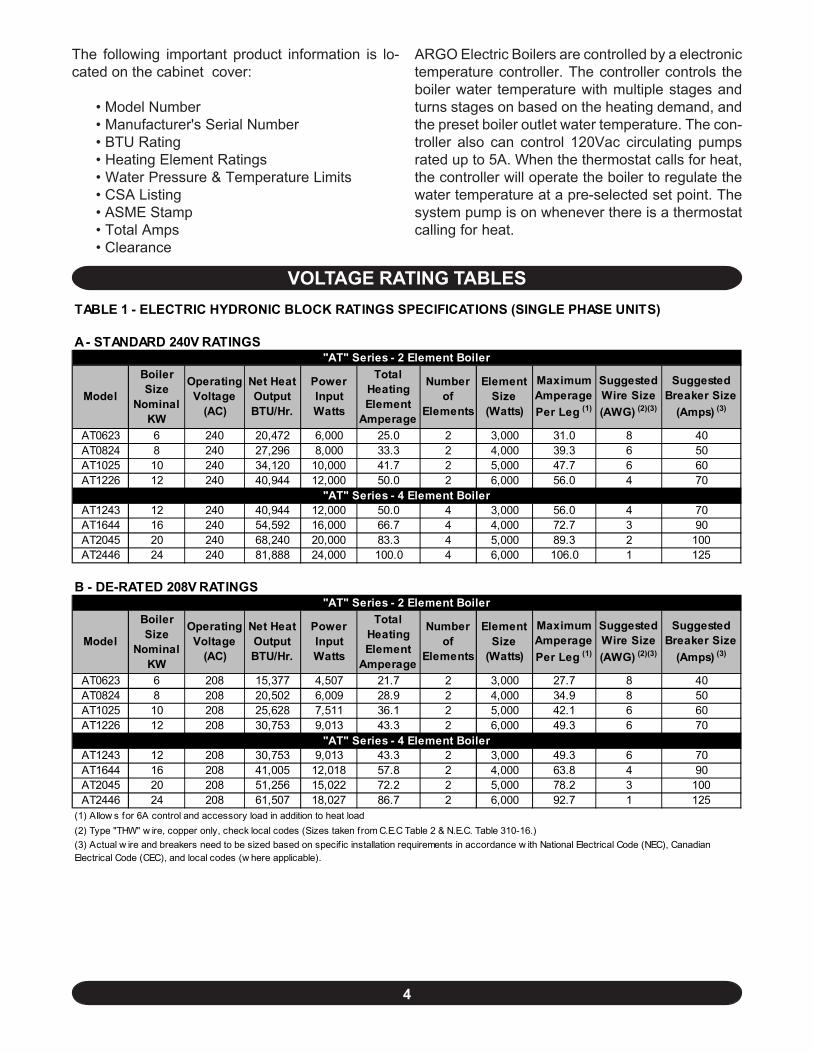
The following important product information is lo-cated on the cabinet cover:
• Model Number• Manufacturer's Serial Number• BTU Rating• Heating Element Ratings• Water Pressure & Temperature Limits• CSA Listing• ASME Stamp• Total Amps• Clearance
ARGO Electric Boilers are controlled by a electronictemperature controller. The controller controls theboiler water temperature with multiple stages andturns stages on based on the heating demand, andthe preset boiler outlet water temperature. The con-troller also can control 120Vac circulating pumpsrated up to 5A. When the thermostat calls for heat,the controller will operate the boiler to regulate thewater temperature at a pre-selected set point. Thesystem pump is on whenever there is a thermostatcalling for heat.
VOLTAGE RATING TABLES
A - STANDARD 240V RATINGS
Model
Boiler Size
Nominal KW
Operating Voltage
(AC)
Net Heat Output BTU/Hr.
Power Input Watts
Total Heating Element
Amperage
Number of
Elements
Element Size
(Watts)
Maximum Amperage Per Leg (1)
Suggested Wire Size (AWG) (2)(3)
Suggested Breaker Size
(Amps) (3)
AT0623 6 240 20,472 6,000 25.0 2 3,000 31.0 8 40AT0824 8 240 27,296 8,000 33.3 2 4,000 39.3 6 50AT1025 10 240 34,120 10,000 41.7 2 5,000 47.7 6 60AT1226 12 240 40,944 12,000 50.0 2 6,000 56.0 4 70
AT1243 12 240 40,944 12,000 50.0 4 3,000 56.0 4 70AT1644 16 240 54,592 16,000 66.7 4 4,000 72.7 3 90AT2045 20 240 68,240 20,000 83.3 4 5,000 89.3 2 100AT2446 24 240 81,888 24,000 100.0 4 6,000 106.0 1 125
B - DE-RATED 208V RATINGS
Model
Boiler Size
Nominal KW
Operating Voltage
(AC)
Net Heat Output BTU/Hr.
Power Input Watts
Total Heating Element
Amperage
Number of
Elements
Element Size
(Watts)
Maximum Amperage Per Leg (1)
Suggested Wire Size (AWG) (2)(3)
Suggested Breaker Size
(Amps) (3)
AT0623 6 208 15,377 4,507 21.7 2 3,000 27.7 8 40AT0824 8 208 20,502 6,009 28.9 2 4,000 34.9 8 50AT1025 10 208 25,628 7,511 36.1 2 5,000 42.1 6 60AT1226 12 208 30,753 9,013 43.3 2 6,000 49.3 6 70
AT1243 12 208 30,753 9,013 43.3 2 3,000 49.3 6 70AT1644 16 208 41,005 12,018 57.8 2 4,000 63.8 4 90AT2045 20 208 51,256 15,022 72.2 2 5,000 78.2 3 100AT2446 24 208 61,507 18,027 86.7 2 6,000 92.7 1 125
"AT" Series - 2 Element Boiler
"AT" Series - 4 Element Boiler
"AT" Series - 2 Element Boiler
TABLE 1 - ELECTRIC HYDRONIC BLOCK RATINGS SPECIFICATIONS (SINGLE PHASE UNITS)
"AT" Series - 4 Element Boiler
(1) Allow s for 6A control and accessory load in addition to heat load(2) Type "THW" w ire, copper only, check local codes (Sizes taken from C.E.C Table 2 & N.E.C. Table 310-16.)(3) Actual w ire and breakers need to be sized based on specif ic installation requirements in accordance w ith National Electrical Code (NEC), Canadian Electrical Code (CEC), and local codes (w here applicable).
5
! !
INSTALLATION PROCEDUREImproper installation, adjustment, alteration, serviceor maintenance can cause injury or property damage.
1. The installation must conform to the requirementsof the authority having jurisdiction or, in absence ofsuch requirements, to the latest revision of theCanadian Electrical Code, CSA C22.1 Part 1, and/orany local regulations in Canada, or the NationalElectrical Code, ANSI/NFPA to (Latest Edition) and/or any local regulations and codes in the USA.Reference should also be made to local Electricutility regulations and other codes in effect in thearea in which the installation is to be made.
2. Where required by the authority having jurisdiction,the installation must conform to American Society ofMechanical Engineers Safety Code for Controls andSafety Devices for Automatically Fired Boilers, ANSI/ASME No. CSD-1.
3. The Boiler is intended for indoor installationonly and not subject to water spray or leakage.
CAUTION
Do not install boiler UNDER potential watersource.
(RULE OF THUMB: Water Under Wires.)
4. Electric Hydronic Block units are provided withmounting brackets for easy wall mounting. The unitmay be mounted directly on the wall by the use of lagscrews or anchor bolts through holes provided, or ona 3/4" plywood panel. On uneven walls, it is suggestedthat a mounting surface be provided such as two 2 x4’s.
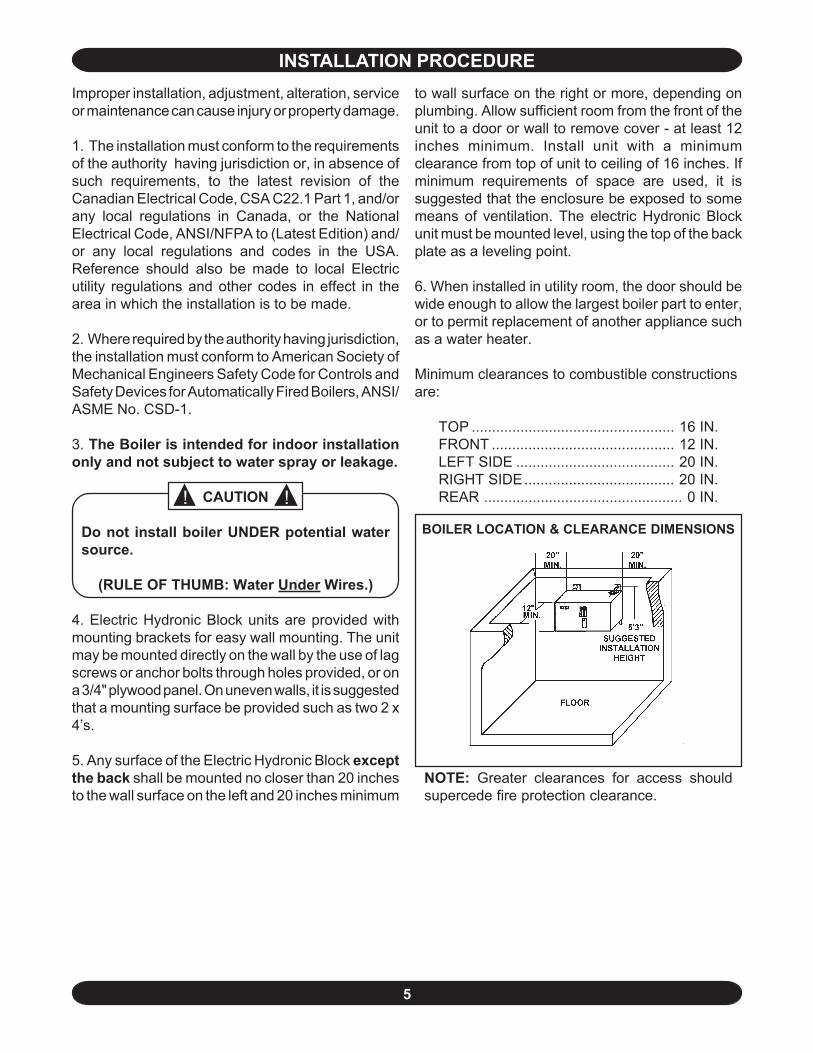
5. Any surface of the Electric Hydronic Block exceptthe back shall be mounted no closer than 20 inchesto the wall surface on the left and 20 inches minimum
to wall surface on the right or more, depending onplumbing. Allow sufficient room from the front of theunit to a door or wall to remove cover - at least 12inches minimum. Install unit with a minimumclearance from top of unit to ceiling of 16 inches. Ifminimum requirements of space are used, it issuggested that the enclosure be exposed to somemeans of ventilation. The electric Hydronic Blockunit must be mounted level, using the top of the backplate as a leveling point.
6. When installed in utility room, the door should bewide enough to allow the largest boiler part to enter,or to permit replacement of another appliance suchas a water heater.
Minimum clearances to combustible constructionsare:
TOP .................................................. 16 IN.FRONT ............................................. 12 IN.LEFT SIDE ....................................... 20 IN.RIGHT SIDE..................................... 20 IN.REAR ................................................. 0 IN.
NOTE: Greater clearances for access shouldsupercede fire protection clearance.
BOILER LOCATION & CLEARANCE DIMENSIONS
6
DESIGN OF WATERCIRCULATING SYSTEM
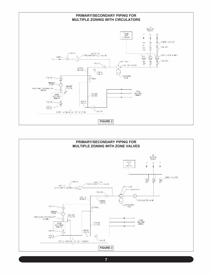
System should be designed as primary/secondarypiping and to operate with a maximum output tem-perature of 180º F or lower and a temperature riseacross the unit of 20º F or lower. Refer to tablesbelow and Figures 2 & 3.
NOTE: To prevent condensation, the return wa-ter temperature must be higher than the roomtemperature in which the boiler is installed.
CONNECTING SUPPLYAND RETURN PIPING
1. Maintain a minimum clearance of one inch to hotwater pipes.
2. Hot water boilers installed above radiation levelmust be provided with a low water cutoff deviceeither as part of the boiler or at the time of boilerinstallation.
NOTE: In some states a low water cutoff device(LWCO) may be required. Check your local codes.
3. When a boiler is connected to a heating systemthat utilizes multiple zoned circulators, each circulatormust be supplied with a flow control valve to preventgravity circulation.
NOTE: Reduced pressure back flow provendermust be present under provisions required by theEnvironmental Protection Agency, (EPA).
4. Suggested plumbing arrangements are illustratedin Figures 2 & 3. The inlet or return pipe is located at
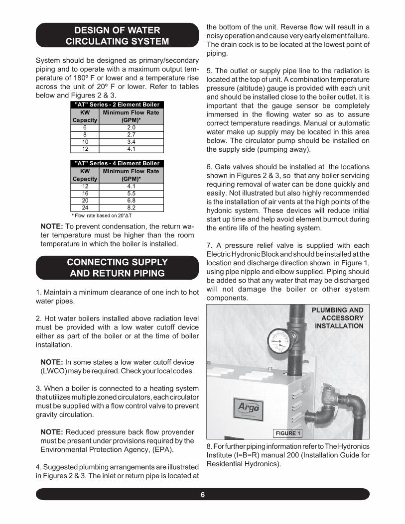
the bottom of the unit. Reverse flow will result in anoisy operation and cause very early element failure.The drain cock is to be located at the lowest point ofpiping.
5. The outlet or supply pipe line to the radiation islocated at the top of unit. A combination temperaturepressure (altitude) gauge is provided with each unitand should be installed close to the boiler outlet. It isimportant that the gauge sensor be completelyimmersed in the flowing water so as to assurecorrect temperature readings. Manual or automaticwater make up supply may be located in this areabelow. The circulator pump should be installed onthe supply side (pumping away).
6. Gate valves should be installed at the locationsshown in Figures 2 & 3, so that any boiler servicingrequiring removal of water can be done quickly andeasily. Not illustrated but also highly recommendedis the installation of air vents at the high points of thehydonic system. These devices will reduce initialstart up time and help avoid element burnout duringthe entire life of the heating system.
7. A pressure relief valve is supplied with eachElectric Hydronic Block and should be installed at thelocation and discharge direction shown in Figure 1,using pipe nipple and elbow supplied. Piping shouldbe added so that any water that may be dischargedwill not damage the boiler or other systemcomponents.
8. For further piping information refer to The HydronicsInstitute (I=B=R) manual 200 (Installation Guide forResidential Hydronics).
FIGURE 1
PLUMBING ANDACCESSORY
INSTALLATION
KW Capacity
Minimum Flow Rate (GPM)*
6 2.08 2.710 3.412 4.1
KW Capacity
Minimum Flow Rate (GPM)*
12 4.116 5.520 6.824 8.2
* Flow rate based on 20°∆T
"AT" Series - 2 Element Boiler
"AT" Series - 4 Element Boiler
7
FIGURE 2
PRIMARY/SECONDARY PIPING FORMULTIPLE ZONING WITH CIRCULATORS
PRIMARY/SECONDARY PIPING FORMULTIPLE ZONING WITH ZONE VALVES
FIGURE 3
8
! !
CONNECTING ELECTRICAL POWER SUPPLY
WIRING THE BOILER
WARNING
DO NOT USE ALUMINUM WIRE!!
Argo Electric Hydronic Boilers are pre-wired for usewith 240-volt, 3 wire, single-phase, 50/60-hertz power.Refer to Table 1B on page 4 for the reduction in boilercapacity when the line voltage is less than 240 volts.
An opening is provided in the jacket bottom panel forthe field wiring, refer to the rating chart forrecommended wire sizes.
All electrical wiring must be done in accordance withthe Canadian Electrical Code, CSA C22.1 Part 1,and /or any local regulations and codes in Canada,or the National Electrical code, ANSI/NFPA 70 (Latestedition) and/or any local regulations and codes inUSA. Verify the nameplate rating and check therelated codes to properly size conductors, switchesand over current protection. Several openings areprovided on the bottom of the cabinet for differentvoltage connections. For wire connections refer tothe wiring diagram on the inside of the boiler frontcover. Do not use aluminum wire!!
All circuit breakers or disconnects ahead of the boilermust be OFF. If boiler contains integral breakers(depending on option), it is recommended that theyare also turned off at this time. Remove the boilerfront cover by removing 4 screws from the top andsides.
When a boiler is used in a zoned system, the zonevalves must be powered from an independent sourceand have electrically isolated end switches or isolatingrelays wired in parallel to the boiler thermostatterminals. Do not attempt to power zone valvesfrom the transformer in the boiler control system!!
WIRING ON CONTROL
PUMP: Connect only 120 Vac 1/6 HP (maximum)pump to terminals C1(L) and C2(N) on the controller.Strip wire ends before inserting into terminal block.Tighten terminal screws. Do not use a pumprequiring greater than 5 amps!!
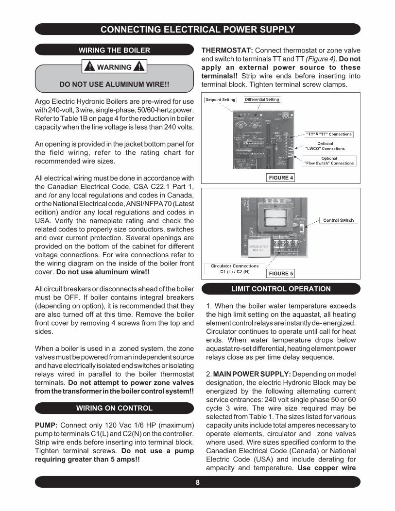
THERMOSTAT: Connect thermostat or zone valveend switch to terminals TT and TT (Figure 4). Do notapply an external power source to theseterminals!! Strip wire ends before inserting intoterminal block. Tighten terminal screw clamps.
LIMIT CONTROL OPERATION
1. When the boiler water temperature exceedsthe high limit setting on the aquastat, all heatingelement control relays are instantly de- energized.Circulator continues to operate until call for heatends. When water temperature drops belowaquastat re-set differential, heating element powerrelays close as per time delay sequence.
2. MAIN POWER SUPPLY: Depending on modeldesignation, the electric Hydronic Block may beenergized by the following alternating currentservice entrances: 240 volt single phase 50 or 60cycle 3 wire. The wire size required may beselected from Table 1. The sizes listed for variouscapacity units include total amperes necessary tooperate elements, circulator and zone valveswhere used. Wire sizes specified conform to theCanadian Electrical Code (Canada) or NationalElectric Code (USA) and include derating forampacity and temperature. Use copper wire
FIGURE 4
FIGURE 5
9
only with insulation rated for 75 °C. Checkstate and local requirements.
NOTE: Read the data name plate beforeconnecting unit so that you will becomefamiliar with the specifications. All electricalconnections to the unit are provided andlocated for ease of proper installation.
IMPORTANT: Use only copper wire of propersize and make sure all terminations are verytight. Do not use aluminum wire!!
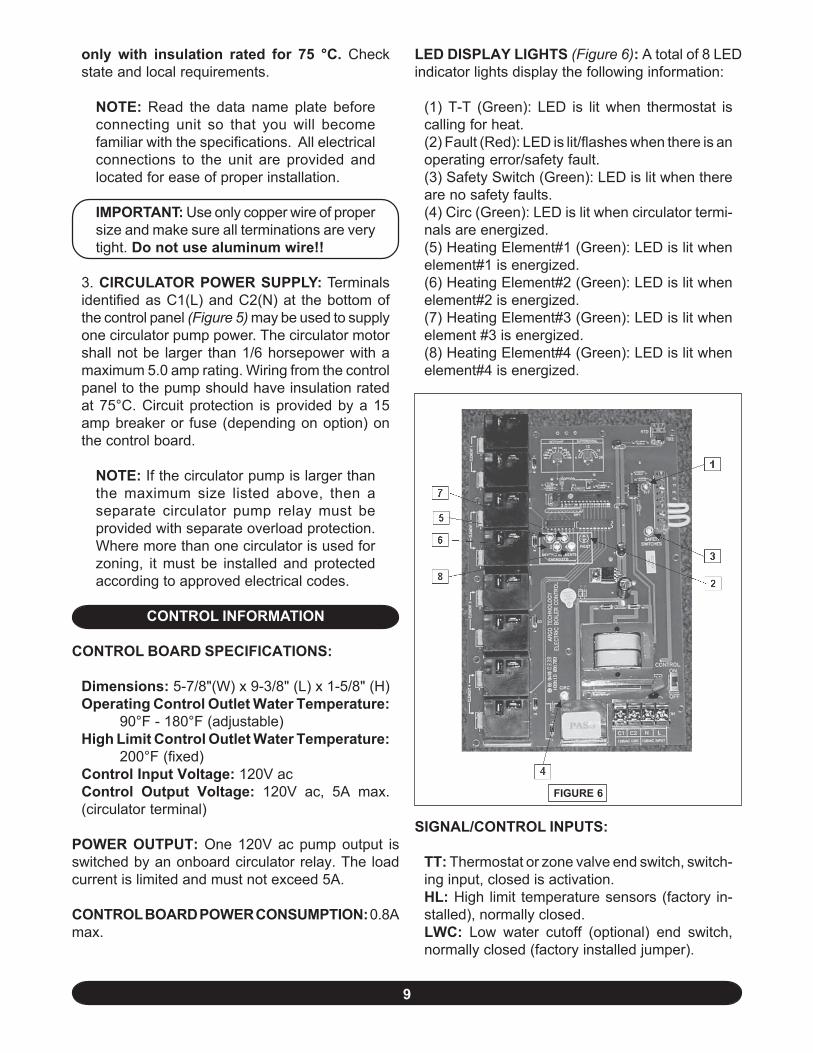
3. CIRCULATOR POWER SUPPLY: Terminalsidentified as C1(L) and C2(N) at the bottom ofthe control panel (Figure 5) may be used to supplyone circulator pump power. The circulator motorshall not be larger than 1/6 horsepower with amaximum 5.0 amp rating. Wiring from the controlpanel to the pump should have insulation ratedat 75°C. Circuit protection is provided by a 15amp breaker or fuse (depending on option) onthe control board.
NOTE: If the circulator pump is larger thanthe maximum size listed above, then aseparate circulator pump relay must beprovided with separate overload protection.Where more than one circulator is used forzoning, it must be installed and protectedaccording to approved electrical codes.
CONTROL INFORMATION
CONTROL BOARD SPECIFICATIONS:
Dimensions: 5-7/8"(W) x 9-3/8" (L) x 1-5/8" (H)Operating Control Outlet Water Temperature:
90°F - 180°F (adjustable)High Limit Control Outlet Water Temperature:
200°F (fixed)Control Input Voltage: 120V acControl Output Voltage: 120V ac, 5A max.(circulator terminal)
POWER OUTPUT: One 120V ac pump output isswitched by an onboard circulator relay. The loadcurrent is limited and must not exceed 5A.
CONTROL BOARD POWER CONSUMPTION: 0.8Amax.
FIGURE 6
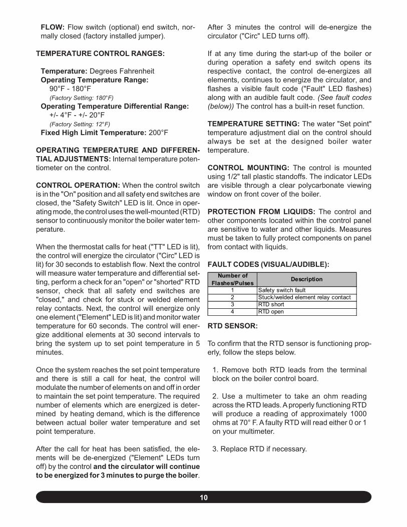
LED DISPLAY LIGHTS (Figure 6): A total of 8 LEDindicator lights display the following information:
(1) T-T (Green): LED is lit when thermostat iscalling for heat.(2) Fault (Red): LED is lit/flashes when there is anoperating error/safety fault.(3) Safety Switch (Green): LED is lit when thereare no safety faults.(4) Circ (Green): LED is lit when circulator termi-nals are energized.(5) Heating Element#1 (Green): LED is lit whenelement#1 is energized.(6) Heating Element#2 (Green): LED is lit whenelement#2 is energized.(7) Heating Element#3 (Green): LED is lit whenelement #3 is energized.(8) Heating Element#4 (Green): LED is lit whenelement#4 is energized.
SIGNAL/CONTROL INPUTS:
TT: Thermostat or zone valve end switch, switch-ing input, closed is activation.HL: High limit temperature sensors (factory in-stalled), normally closed.LWC: Low water cutoff (optional) end switch,normally closed (factory installed jumper).
10
FLOW: Flow switch (optional) end switch, nor-mally closed (factory installed jumper).
TEMPERATURE CONTROL RANGES:
Temperature: Degrees FahrenheitOperating Temperature Range:
90°F - 180°F(Factory Setting: 180°F)
Operating Temperature Differential Range:+/- 4°F - +/- 20°F(Factory Setting: 12°F)
Fixed High Limit Temperature: 200°F
OPERATING TEMPERATURE AND DIFFEREN-TIAL ADJUSTMENTS: Internal temperature poten-tiometer on the control.
CONTROL OPERATION: When the control switchis in the "On" position and all safety end switches areclosed, the "Safety Switch" LED is lit. Once in oper-ating mode, the control uses the well-mounted (RTD)sensor to continuously monitor the boiler water tem-perature.
When the thermostat calls for heat ("TT" LED is lit),the control will energize the circulator ("Circ" LED islit) for 30 seconds to establish flow. Next the controlwill measure water temperature and differential set-ting, perform a check for an "open" or "shorted" RTDsensor, check that all safety end switches are"closed," and check for stuck or welded elementrelay contacts. Next, the control will energize onlyone element ("Element" LED is lit) and monitor watertemperature for 60 seconds. The control will ener-gize additional elements at 30 second intervals tobring the system up to set point temperature in 5minutes.
Once the system reaches the set point temperatureand there is still a call for heat, the control willmodulate the number of elements on and off in orderto maintain the set point temperature. The requirednumber of elements which are energized is deter-mined by heating demand, which is the differencebetween actual boiler water temperature and setpoint temperature.
After the call for heat has been satisfied, the ele-ments will be de-energized ("Element" LEDs turnoff) by the control and the circulator will continueto be energized for 3 minutes to purge the boiler.
After 3 minutes the control will de-energize thecirculator ("Circ" LED turns off).
If at any time during the start-up of the boiler orduring operation a safety end switch opens itsrespective contact, the control de-energizes allelements, continues to energize the circulator, andflashes a visible fault code ("Fault" LED flashes)along with an audible fault code. (See fault codes(below)) The control has a built-in reset function.
TEMPERATURE SETTING: The water "Set point"temperature adjustment dial on the control shouldalways be set at the designed boiler watertemperature.
CONTROL MOUNTING: The control is mountedusing 1/2" tall plastic standoffs. The indicator LEDsare visible through a clear polycarbonate viewingwindow on front cover of the boiler.
PROTECTION FROM LIQUIDS: The control andother components located within the control panelare sensitive to water and other liquids. Measuresmust be taken to fully protect components on panelfrom contact with liquids.
FAULT CODES (VISUAL/AUDIBLE):
RTD SENSOR:
To confirm that the RTD sensor is functioning prop-erly, follow the steps below.
1. Remove both RTD leads from the terminalblock on the boiler control board.
2. Use a multimeter to take an ohm readingacross the RTD leads. A properly functioning RTDwill produce a reading of approximately 1000ohms at 70° F. A faulty RTD will read either 0 or 1on your multimeter.
3. Replace RTD if necessary.
Number of Flashes/Pulses Description
1 Safety switch fault2 Stuck/welded element relay contact3 RTD short4 RTD open
11
- D
RY C
ONTA
CT F
IELD
WIR
ING
(PO
SE D
ES F
ILS
DE
CO
NTA
CT
SEC
SUR
LE
CH
AMP
)LO
AD C
ENTE
R(C
ENTR
E D
E C
HAR
GE)
ON
(OU
VERT
)
TRAN
SFO
RM
ER(T
RA
NSFO
RMA
TEU
R)
NEU
TRAL
BLO
CK
(BLO
C N
EUT
RE)
EQ
UIP
MEN
T G
RO
UNDI
NG
LU
G(T
ENO
N D
E P
RIS
E Á
LA
TER
RE
DE
L É
QUI
PM
ENT)
WH
T (B
LAN
C)
WHT
/BLK
(BL
ANC
/NO
IR)
CIR
CU
LATO
R P
UM
P, B
Y O
THE
RS(P
OM
PE D
U C
IRC
ULA
TEUR
, OU
AU
TRES
)
N
SO
URC
E PO
WER
, 240
V/60
HZ/
1PH
3-W
IRE,
BY
OTH
ERS
(SO
URC
E D
U C
OU
RAN
T, 2
40V/
60H
Z/1P
H 3-
FIL
S, O
U A
UTR
ES)
120V
AC
INPU
T(E
NTR
ÉE)
N
CIR
CN
OT
USE
D(N
ON
UTIL
ISÉ)
CIR
CUL
ATO
R R
ELA
Y(R
ELA
IS D
UCI
RCU
LATE
UR)
LN C2
C1 12
0VA
CC
IRC
NO
T U
SED
(NO
N UT
ILIS
É)
OFF
(FER
MÉ)
BLK
(NO
IR)
21
LL1
L2
ARGO
"AT"
ELE
CTRI
C BO
ILER
SCHE
MATIC
WIR
ING
DIAG
RAM
2 ELE
MENT
BOI
LER,
WITH
BRE
AKER
S(D
IAGR
AMM
E SC
HÉMA
TIQU
E DE
LA P
OSE
DES
FILS
D'U
NE C
HAUD
IÈRE
À 2
ÉLÉM
ENTS
)
- 24
0 V
OLT
FIE
LD W
IRIN
G (P
OSE
DE
S FI
LS 2
40 V
OLT
SUR
LE
CHA
MP)
- 12
0 V
OLT
FIE
LD W
IRIN
G (P
OSE
DE
S FI
LS 1
20 V
OLT
SUR
LE
CHA
MP)
- 24
0 V
OLT
WIR
ING
(PO
SE
DES
FIL
S 24
0 V
OLT
)
- 12
0 V
OLT
WIR
ING
(PO
SE
DES
FIL
S 12
0 V
OLT
)
OPT
ION
AL
LWC
O, B
Y OT
HERS
(LW
CO
- FA
CU
LTAT
IF -
OU
AU
TRES
)
SOU
RCE
PO
WE
R, 1
20V
/60H
Z/1
PH ,
BY O
THE
RS
(SO
URC
E D
U C
OU
RAN
T, 1
20V/
60H
Z/1P
H, O
U A
UTR
ES)
OPT
IONA
L FL
OW
SW
ITC
H, B
Y O
THE
RS(IN
TER
RUP
TEU
R D
E D
ÉBI
T -
FAC
ULT
ATIF
, OU
AUT
RES)
THER
MO
STA
T, B
Y O
THER
S(T
HER
MOS
TAT,
OU
AUT
RES)
ELEM
ENT
#1(É
LÉM
ENT
#1)
ELE
ME
NT
#1 R
ELA
YS
(REL
AIS
DE
LÉLÉ
ME
NT #
1)
H2
HEA
TING
ELE
MEN
TS
ENER
GIZ
ED(A
CTIV
ATI
ON D
ES
ÉLÉM
ENT
S D
E CH
AUFF
AGE) AR
GO E
LEC
TRON
IC B
OIL
ER C
ONT
RO
L(C
ON
TRÔ
LE É
LECT
RON
IQUE
DE
LA
CH
AUDI
ÈRE
AR
GO
)
NO
T U
SED
(NO
N UT
ILIS
É)
NO
T U
SED
(NO
N UT
ILIS
É)
RED
(RO
UG
E)
CO
NTR
OL
(CO
NTR
ÔLE
)
HIG
H L
IMIT
SAF
ETY
SW
ITCH
, AUT
O R
ESET
(INT
ERRU
PTEU
R D
E S
ÉCU
RITÉ
HAU
TE L
IMIT
E,
REM
ISE
EN
MAR
CHE
AU
TOM
ATIQ
UE
)
T-T
SAF
ETY
SW
ITC
HES
(INTE
RRU
PTEU
RS
DE
SÉCU
RITÉ
)2
31
4FA
ULT
(DÉF
AILL
ANCE
)
H1
L2 L2
ELE
MEN
T #2
(ÉLÉ
MEN
T #2
)
H2
ELE
ME
NT
#2 R
ELA
YS
(REL
AIS
DE
LÉLÉ
ME
NT #
2)
L1
TT TT HL
HL
RE
D (R
OUG
E)
LWC
FLO
WFL
OW
FAC
TORY
INS
TALL
ED JU
MP
ERS
(JAR
RETI
ÉRE
S IN
STA
LLÉE
S Á
LUS
INE
)
LWC
DIFF
EREN
TIAL
(DIF
FÉRE
NTI
EL)
SETP
OIN
T(R
ÉGL
AGE)
H1
L1RT
D
RTD
WAT
ER T
EMP
ERAT
UR
E S
ENSO
R
(DÉ
TEC
TEUR
DE
LA T
EMP
ÉRAT
UR
E D
E LE
AU R
TD)WH
T (B
LAN
C)
- D
RY C
ONTA
CT W
IRIN
G (P
OSE
DE
S FI
LS D
E C
ON
TACT
SEC
)
WIR
E L
EGEN
D /
(LÉG
END
E D
ES F
ILS
)
RE
D (R
OUG
E)
HIG
H L
IMIT
SAF
ETY
SW
ITCH
, AUT
O R
ESET
(INT
ERRU
PTEU
R D
E S
ÉCU
RITÉ
HAU
TE L
IMIT
E,
REM
ISE
EN
MAR
CHE
AU
TOM
ATIQ
UE
)
WHT
(BLA
NC)
WH
T/BL
K (B
LAN
C/N
OIR
)
WH
T (B
LAN
C)
WH
T (B
LAN
C)
WHT
/BLK
(BL
ANC
/NO
IR)
WHT
/BLK
(BL
ANC
/NO
IR)
WH
T (B
LAN
C)
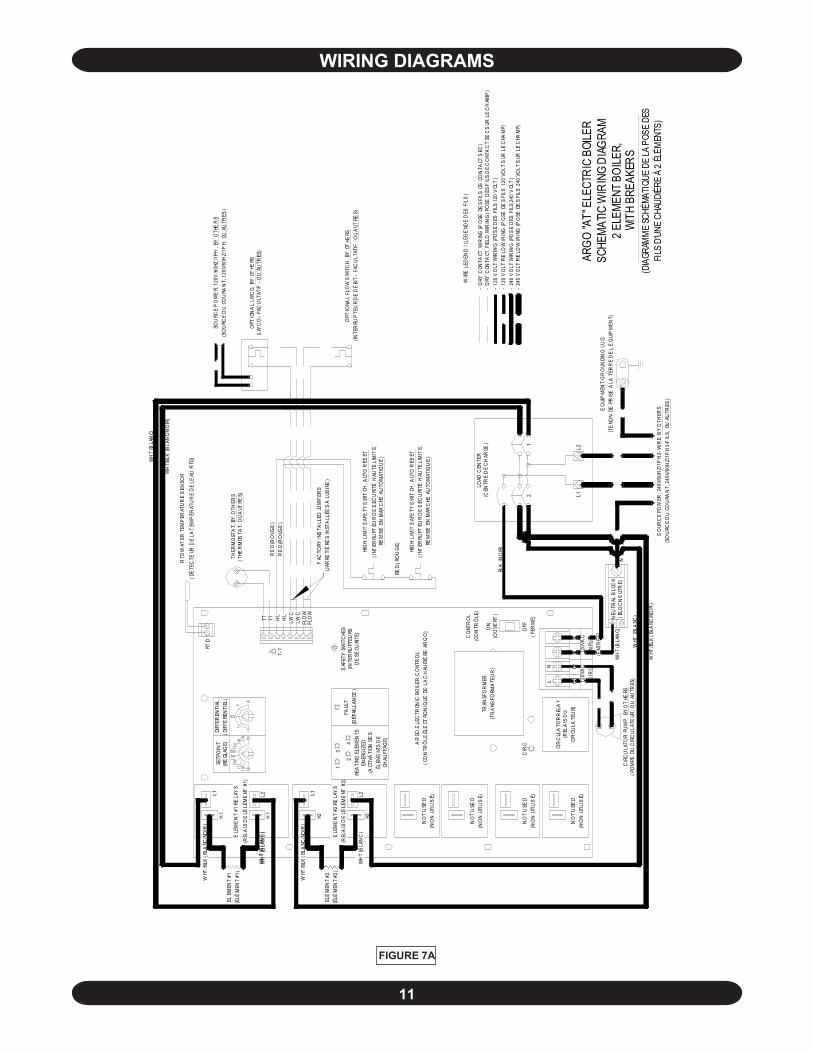
FIGURE 7A
WIRING DIAGRAMS
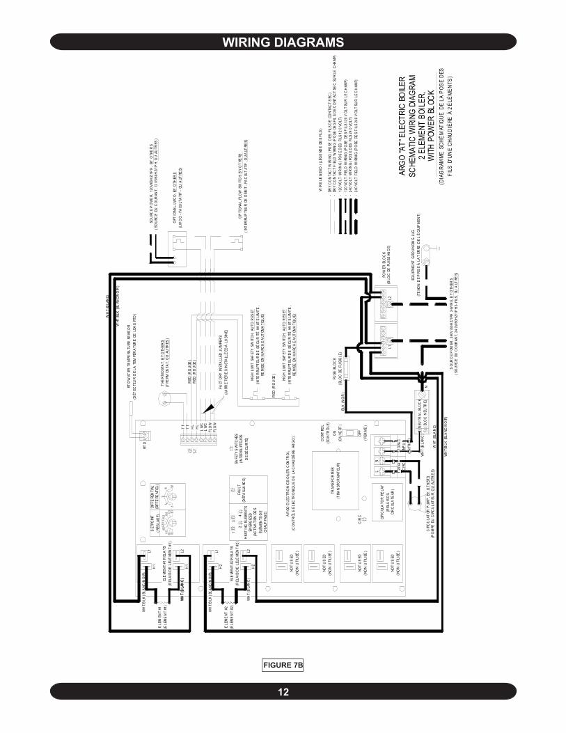
12
FIGURE 7B
HIG
H L
IMIT
SAF
ETY
SW
ITC
H, A
UTO
RES
ET(IN
TER
RUPT
EUR
DE
SÉ
CUR
ITÉ
HAUT
E LI
MIT
E,
REM
ISE
EN
MA
RCH
E A
UTOM
ATI
QU
E)
HEA
TIN
G E
LEM
ENTS
EN
ERG
IZED
(AC
TIVA
TION
DE
S ÉL
ÉMEN
TS D
E CH
AUF
FAG
E)
SO
URC
E P
OWER
, 240
V/6
0HZ/
1PH
3-W
IRE,
BY
OTH
ERS
(SO
URC
E D
U C
OUR
ANT,
24
0V/6
0HZ/
1PH
3-FI
LS,
OU A
UTRE
S)
EQU
IPM
ENT
GRO
UN
DIN
G L
UG(T
ENO
N D
E P
RIS
E Á
LA
TER
RE D
E L
ÉQ
UIP
MEN
T)
N
NEU
TRA
L BL
OC
K(B
LOC
NEU
TRE)
CIR
CU
LAT
OR P
UMP
, BY
OTH
ERS
(PO
MPE
DU
CIR
CU
LAT
EUR,
OU
AU
TRE
S)W
HT (B
LAN
C)
WH
T/B
LK (
BLA
NC/N
OIR
)
BLK
(NOI
R)
NOT
US
ED(N
ON
UTI
LISÉ
)
NOT
US
ED(N
ON
UTI
LISÉ
)
L
OFF
(FER
MÉ
)
120
VAC
CIR
C
C1
C2N
LCI
RC
ULA
TOR
RE
LAY
(REL
AIS
DU
CIR
CUL
ATE
UR)
CIR
C
N 120V
AC
INP
UT
(EN
TRÉE
)
WH
T (B
LAN
C)
NOT
US
ED(N
ON
UTI
LISÉ
)
NOT
US
ED(N
ON
UTI
LISÉ
)
HIG
H L
IMIT
SAF
ETY
SW
ITC
H, A
UTO
RES
ET(IN
TER
RUPT
EUR
DE
SÉ
CUR
ITÉ
HAUT
E LI
MIT
E,
REM
ISE
EN
MA
RCH
E A
UTOM
ATI
QU
E)
CO
NTRO
L(C
ON
TRÔ
LE)
RED
(RO
UGE
)
AR
GO E
LEC
TRO
NIC
BO
ILER
CON
TRO
L(C
ON
TRÔL
E É
LEC
TRO
NIQ
UE
DE
LA
CH
AUDI
ÈRE
AR
GO
)
TRA
NSFO
RM
ER(T
RAN
SFO
RM
ATEU
R)O
N(O
UVE
RT)
ARGO
"AT"
ELE
CTRI
C BO
ILER
SCHE
MATIC
WIR
ING
DIAG
RAM
2 ELE
MENT
BOI
LER,
WITH
POW
ER BL
OCK
(DIA
GRA
MME
SCH
ÉMAT
IQUE
DE
LA P
OSE
DES
FILS
D'U
NE C
HAUD
IÈRE
À 2
ÉLÉ
MENT
S)
- 1
20 V
OLT
FIE
LD W
IRIN
G (P
OSE
DE
S F
ILS
120
VO
LT S
UR
LE
CH
AMP)
- 2
40 V
OLT
WIR
ING
(PO
SE
DES
FIL
S 24
0 VO
LT)
- 2
40 V
OLT
FIE
LD W
IRIN
G (P
OSE
DE
S F
ILS
240
VO
LT S
UR
LE
CH
AMP)
WIR
E LE
GEN
D / (
LÉG
END
E D
ES
FILS
)
- D
RY
CO
NTA
CT
WIR
ING
(PO
SE D
ES F
ILS
DE
CON
TAC
T S
EC)
- 1
20 V
OLT
WIR
ING
(PO
SE
DES
FIL
S 12
0 VO
LT)
- D
RY
CO
NTA
CT
FIE
LD W
IRIN
G (P
OSE
DE
S FI
LS
DE
CO
NTAC
T SE
C S
UR
LE C
HAM
P)
WHT
/BLK
(BL
ANC/
NO
IR)
WH
T (B
LAN
C)
WH
T/B
LK (
BLA
NC/N
OIR
)
WH
T (B
LAN
C)
WH
T (B
LAN
C)
L1
ELE
MEN
T #2
REL
AYS
(REL
AIS
DE
LÉL
ÉM
ENT
#2)
H2
ELE
ME
NT #
2(É
LÉM
EN
T #2
)
L2L2H
1
H2
RED
(RO
UGE
)
LW
C
FACT
ORY
INST
ALL
ED J
UM
PER
S(J
ARR
ETI
ÉRE
S IN
STA
LLÉ
ES Á
LU
SIN
E)
FLO
WFL
OW
LW
C
RED
(RO
UGE
)H
LH
LT
TT
T
FAU
LT(D
ÉFA
ILLA
NCE)
41
32
SAFE
TY S
WIT
CHE
S(IN
TER
RUPT
EURS
D
E SÉ
CURI
TÉ)
T-T
WH
T/B
LK (
BLA
NC/N
OIR
)L1
H1
ELE
MEN
T #1
REL
AYS
(REL
AIS
DE
LÉL
ÉM
ENT
#1)
ELE
MEN
T #1
(ÉLÉ
ME
NT
#1)
WH
T (B
LAN
C)
RTD
WAT
ER T
EM
PERA
TURE
SE
NSO
R(D
ÉTEC
TEU
R D
E LA
TEM
PÉR
ATU
RE
DE
LEA
U R
TD)
RTD
SET
POIN
T(R
ÉGLA
GE)
DIFF
ERE
NTI
AL(D
IFFÉ
RENT
IEL)
THE
RM
OST
AT,
BY
OTH
ERS
(THE
RMOS
TAT,
OU
AUTR
ES)
OPT
IONA
L LW
CO
, BY
OTH
ERS
(LW
CO
- FA
CULT
ATI
F -
OU A
UTRE
S)
OP
TIO
NAL
FLO
W S
WIT
CH,
BY
OT
HERS
(INT
ERRU
PTE
UR
DE
DÉB
IT -
FAC
ULT
ATIF
, OU
AUT
RES)
SOU
RCE
PO
WE
R, 1
20V/
60H
Z/1P
H ,
BY O
THE
RS
(SO
URC
E D
U C
OUR
ANT,
12
0V/6
0HZ/
1PH,
OU
AU
TRES
)
L1PO
WER
BLO
CK
(BLO
C D
E P
UIS
SAN
CE)
L2
FUSE
BLO
CK
(BLO
C D
E F
USI
BLE
)
WIRING DIAGRAMS
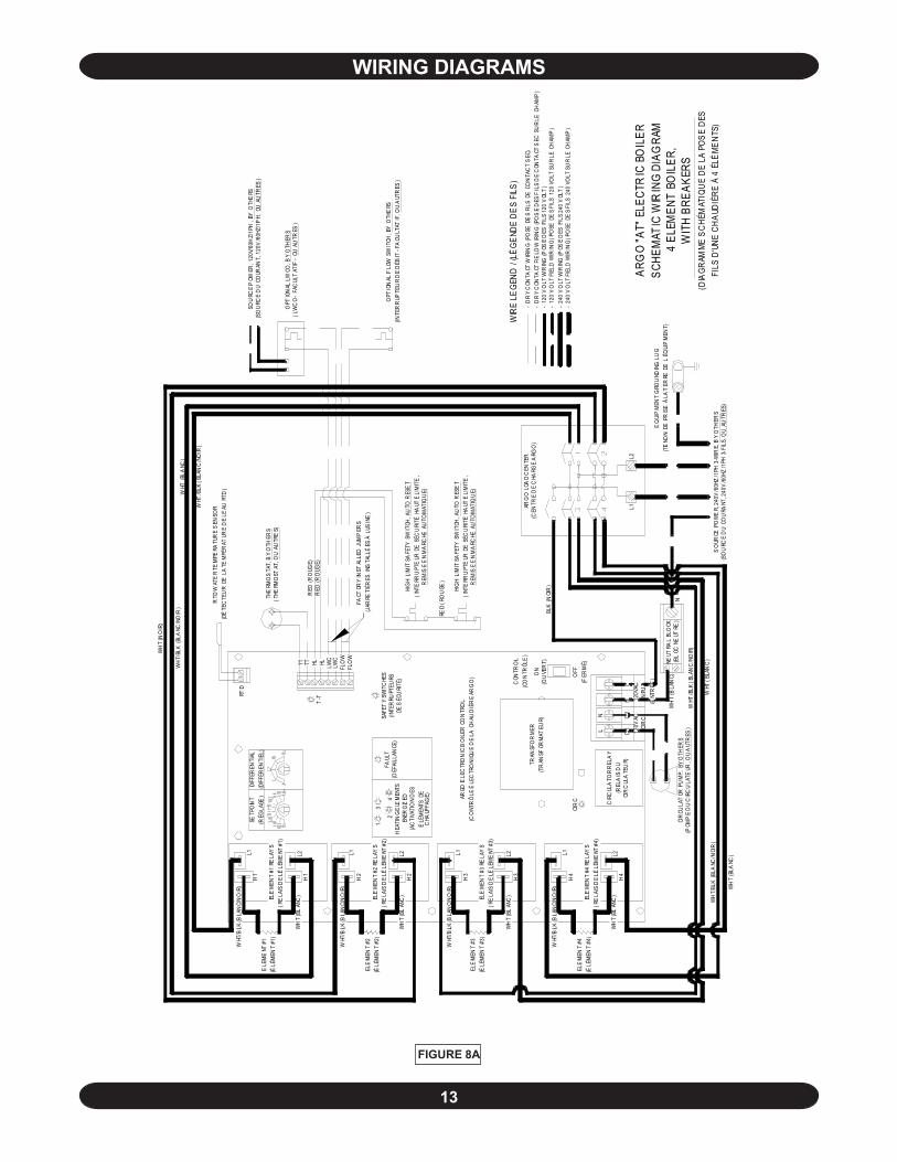
13
FIGURE 8A
SO
URCE
PO
WE
R, 2
40V
/60H
Z/1
PH 3
-WIR
E, B
Y O
THER
S(S
OU
RCE
DU
CO
URA
NT, 2
40V
/60H
Z/1
PH 3-
FILS
, OU
AU
TRES
)
NEUT
RAL
BLO
CK(B
LOC
NE
UTRE
)
WH
T/BL
K (B
LANC
/NOI
R)
WH
T (B
LANC
)
CIR
CULA
TOR
PU
MP,
BY
OTH
ERS
(POM
PE
DU
CIR
CU
LATE
UR, O
U A
UTR
ES)
N
WHT
(BL
ANC
)
WHT
/BLK
(BL
ANC
/NO
IR)
WH
T (B
LAN
C)
WH
T (B
LAN
C) EL
EM
ENT
#4 R
ELA
YS
(RE
LAIS
DE
LÉLÉ
ME
NT #
4)
WHT
/BLK
(BLA
NC/
NO
IR)
ELE
MEN
T #4
(ÉLÉ
MEN
T #4
)
OFF
(FER
MÉ)
N C2
120V
ACCI
RC
L C1
H4
CIR
CUL
ATO
R R
ELA
Y(R
ELA
IS D
UCI
RC
ULA
TEU
R)
L2
LN 12
0VAC
INPU
T(E
NTR
ÉE)
TRAN
SFO
RM
ER(T
RAN
SFOR
MAT
EUR)
H3
L2 L1H
4CI
RC
ON
(OU
VER
T)
CON
TRO
L(C
ON
TRÔL
E)
BLK
(NOI
R)
EQ
UIP
MEN
T G
ROU
NDIN
G L
UG
(TE
NON
DE
PR
ISE
Á L
A T
ERRE
DE
L É
QUI
PM
ENT)
ARG
O "A
T" E
LECT
RIC
BO
ILER
SCHE
MAT
IC W
IRIN
G DI
AGRA
M4
ELEM
ENT
BOIL
ER,
WIT
H BR
EAKE
RS(D
IAGR
AMME
SCH
ÉMAT
IQUE
DE
LA P
OSE
DES
FILS
D'UN
E CH
AUDI
ÈRE
À 4
ÉLÉM
ENTS
)
- D
RY
CON
TACT
WIR
ING
(PO
SE D
ES
FILS
DE
CO
NTA
CT
SEC
)-
DR
Y C
ONTA
CT F
IELD
WIR
ING
(PO
SE
DES
FIL
S D
E C
ONTA
CT S
EC S
UR
LE C
HAM
P)
- 24
0 V
OLT
FIE
LD W
IRIN
G (P
OSE
DE
S FI
LS 2
40 V
OLT
SU
R LE
CH
AMP
)
- 12
0 V
OLT
FIE
LD W
IRIN
G (P
OSE
DE
S FI
LS 1
20 V
OLT
SU
R LE
CH
AMP
)
L2L1AR
GO
LOA
D C
ENTE
R(C
ENTR
E D
E C
HARG
E A
RGO
)
WIR
E LE
GEND
/ (LÉ
GEND
E DE
S FIL
S)
- 12
0 V
OLT
WIR
ING
(POS
E D
ES F
ILS
120
VOL
T)
- 24
0 V
OLT
WIR
ING
(POS
E D
ES F
ILS
240
VOL
T)
RTD
WAT
ER
TEM
PERA
TUR
E S
ENSO
R(D
ÉTE
CTE
UR
DE
LA
TEM
PÉR
ATUR
E D
E LE
AU R
TD)
THE
RMO
STA
T, B
Y O
THER
S(T
HERM
OST
AT, O
U A
UTR
ES)
FACT
ORY
INST
ALLE
D J
UMP
ERS
(JAR
RETI
ÉRES
INS
TALL
ÉES
Á L
USIN
E)
HIG
H L
IMIT
SA
FETY
SW
ITCH
, AU
TO R
ESE
T(I
NTE
RRU
PTE
UR D
E S
ÉCU
RITÉ
HA
UTE
LIM
ITE
, R
EMIS
E E
N M
ARC
HE A
UTO
MAT
IQU
E)
RED
(RO
UGE)
T-T
HL
ELE
MEN
T #2
RE
LAY
S(R
ELA
IS D
E LÉ
LÉM
ENT
#2)
ELE
MEN
T #3
RE
LAY
S(R
ELA
IS D
E LÉ
LÉM
ENT
#3)
WHT
/BLK
(BLA
NC/
NO
IR)
ELE
MEN
T #3
(ÉLÉ
MEN
T #3
)
ELE
MEN
T #2
(ÉLÉ
MEN
T #2
)
H2
HEA
TIN
G E
LEM
ENTS
EN
ERG
IZED
(AC
TIVA
TIO
N D
ES
ÉLÉ
MEN
TS D
E C
HAUF
FAG
E) ARGO
ELE
CTR
ON
IC B
OIL
ER C
ON
TRO
L(C
ONT
RÔ
LE É
LEC
TRO
NIQ
UE
DE
LA C
HAU
DIÈ
RE
ARG
O)
H3
L1
RED
(RO
UGE
)
SAFE
TY
SWIT
CHE
S(IN
TER
RUPT
EURS
DE
SÉC
URI
TÉ)
H2
L1
FAUL
T(D
ÉFAI
LLAN
CE)
42
L2
31
LWC
FLO
WFL
OW
LWC
ELE
MEN
T #1
RE
LAY
S(R
ELA
IS D
E LÉ
LÉM
ENT
#1)
WH
T (B
LAN
C)
ELE
ME
NT #
1(É
LÉM
ENT
#1)
DIFF
EREN
TIAL
(DIF
FÉR
ENTI
EL)
H1
L1SE
TPO
INT
(RÉG
LAGE
)
H1
L2TT TT HL
RTD
WH
T (N
OIR
)
WH
T/BL
K (B
LANC
/NO
IR)
OPT
ION
AL F
LOW
SW
ITCH
, BY
OTH
ERS
(INTE
RR
UPTE
UR
DE
DÉB
IT -
FACU
LTAT
IF, O
U A
UTR
ES)
SOU
RCE
POW
ER, 1
20V/
60H
Z/1P
H ,
BY O
THE
RS(S
OU
RCE
DU
COUR
ANT,
120
V/6
0HZ/
1PH,
OU
AU
TRES
)
OPT
ION
AL L
WCO
, BY
OTH
ERS
(LW
CO
- FA
CUL
TAT
IF -
OU
AU
TRES
)
WHT
(BLA
NC)
WHT
/BLK
(BL
ANC
/NO
IR)
WHT
/BLK
(BLA
NC/
NO
IR)
WH
T (B
LAN
C)
WHT
/BLK
(BLA
NC/
NO
IR)
WH
T (B
LAN
C)
HIG
H L
IMIT
SA
FETY
SW
ITCH
, AU
TO R
ESE
T(I
NTE
RRU
PTE
UR D
E S
ÉCU
RITÉ
HA
UTE
LIM
ITE
, R
EMIS
E E
N M
ARC
HE A
UTO
MAT
IQU
E)
RED
(RO
UGE)
WIRING DIAGRAMS
14
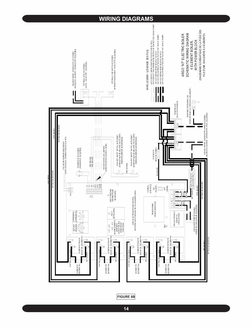
FIGURE 8B
WH
T/B
LK (B
LAN
C/N
OIR
)
NEU
TRAL
BLO
CK
(BLO
C N
EUTR
E)C
IRCU
LATO
R P
UM
P, B
Y O
THER
S(P
OM
PE D
U C
IRC
ULA
TEUR
, OU
AUT
RES
)
WH
T/B
LK (B
LAN
C/N
OIR
)
WH
T (B
LAN
C)
WHT
(BLA
NC)
WH
T (B
LAN
C)
WH
T/BL
K (B
LANC
/NOI
R)
OFF
(FER
MÉ)
ELE
MEN
T #4
(ÉLÉ
MEN
T #4
)
CIR
CUL
ATO
R R
ELA
Y(R
ELAI
S D
UC
IRCU
LAT
EUR)
WH
T (B
LAN
C)L2
H4
ELE
ME
NT #
4 R
ELA
YS(R
ELAI
S D
E L
ÉLÉ
MEN
T #4
)
120V
AC
INPU
T(E
NTRÉ
E)
NL
C1L 12
0VAC
CIR
CC2N
CIR
CH
4L1L2
H3
WHT
/BLK
(BL
ANC
/NO
IR)
WH
T (B
LAN
C)C
ONT
RO
L(C
ONTR
ÔLE
)
ON
(OU
VERT
)
TRA
NSFO
RM
ER(T
RAN
SFOR
MAT
EUR)
HL
T-T
HEAT
ING
ELE
MEN
TS
ENER
GIZE
D(A
CTIV
ATI
ON D
ES
ÉLÉM
ENT
S D
E C
HAU
FFAG
E)
H2
ARG
O E
LEC
TRO
NIC
BO
ILER
CO
NTR
OL(C
ON
TRÔL
E É
LECT
RON
IQU
E DE
LA
CHA
UDIÈ
RE
ARG
O)
WHT
/BLK
(BL
ANC
/NO
IR)
L1H
3EL
EM
ENT
#3(É
LÉM
ENT
#3)
ELE
ME
NT #
3 R
ELA
YS(R
ELAI
S D
E L
ÉLÉ
MEN
T #3
)
WH
T (B
LAN
C)
13
L2
2
L1H
2EL
EM
ENT
#2(É
LÉM
ENT
#2)
WHT
/BLK
(BL
ANC
/NO
IR)
ELE
ME
NT #
2 R
ELA
YS(R
ELAI
S D
E L
ÉLÉ
MEN
T #2
)
LWC
FLO
WFL
OW
LWC
4FA
ULT
(DÉ
FAIL
LANC
E)
SAFE
TY S
WIT
CHE
S(IN
TERR
UPT
EUR
S
DE S
ÉCU
RITÉ
)
SETP
OIN
T(R
ÉGL
AGE)
WHT
/BLK
(BL
ANC
/NO
IR)
L2H1
L1H1
ELE
ME
NT #
1(É
LÉM
ENT
#1)
WH
T (B
LAN
C)ELE
ME
NT #
1 R
ELA
YS(R
ELAI
S D
E L
ÉLÉ
MEN
T #1
)
RTD
HL
TTTT
DIF
FER
ENTI
AL
(DIF
FÉR
ENT
IEL)
WHT
(NO
IR)
ARG
O "A
T" E
LEC
TRIC
BOI
LER
SCHE
MAT
IC W
IRIN
G D
IAGR
AM4
ELEM
ENT
BOIL
ER,
WIT
H PO
WER
BLO
CK
EQUI
PM
ENT
GR
OUN
DIN
G L
UG(T
ENO
N D
E P
RIS
E Á
LA
TER
RE
DE
L ÉQ
UIP
ME
NT)
(DIA
GRAM
ME S
CHÉM
ATIQ
UE D
E LA
POS
E DE
S FI
LS D
'UNE
CHA
UDIÈ
RE À
4 É
LÉM
ENTS
)S
OUR
CE P
OW
ER, 2
40V/
60H
Z/1P
H 3
-WIR
E, B
Y O
THER
S(S
OU
RCE
DU
CO
URA
NT, 2
40V/
60H
Z/1P
H 3
-FIL
S, O
U A
UTR
ES)
N
- 24
0 V
OLT
WIR
ING
(PO
SE D
ES
FILS
240
VO
LT)
- 12
0 V
OLT
WIR
ING
(PO
SE D
ES
FILS
120
VO
LT)
WIR
E LE
GEND
/ (LÉ
GEND
E DE
S FI
LS)
- 12
0 V
OLT
FIE
LD W
IRIN
G (P
OSE
DES
FIL
S 12
0 V
OLT
SU
R LE
CH
AMP
)
- 24
0 V
OLT
FIE
LD W
IRIN
G (P
OSE
DES
FIL
S 24
0 V
OLT
SU
R LE
CH
AMP
)
- D
RY
CON
TACT
FIE
LD W
IRIN
G (P
OSE
DE
S FI
LS D
E C
ON
TAC
T S
EC S
UR
LE C
HAM
P)
- D
RY
CON
TACT
WIR
ING
(POS
E D
ES F
ILS
DE
CO
NTAC
T SE
C)
RED
(RO
UG
E)
OPT
ION
AL F
LOW
SW
ITC
H, B
Y O
THER
S(IN
TER
RUPT
EUR
DE
DÉB
IT -
FACU
LTA
TIF,
OU
AU
TRE
S)H
IGH
LIM
IT S
AFET
Y S
WIT
CH, A
UTO
RES
ET
(INTE
RR
UPTE
UR
DE
SÉC
URI
TÉ H
AU
TE L
IMIT
E,
REM
ISE
EN M
ARC
HE A
UTO
MAT
IQU
E)
RED
(RO
UGE)
HIG
H LI
MIT
SAF
ETY
SW
ITCH
, AU
TO R
ESE
T(IN
TER
RUP
TEU
R D
E S
ÉCU
RITÉ
HA
UTE
LIM
ITE
, R
EMIS
E EN
MAR
CHE
AU
TOM
ATIQ
UE)
FAC
TOR
Y IN
STA
LLED
JUM
PER
S(J
ARR
ETIÉ
RES
INST
ALLÉ
ES Á
LUS
INE
)
OPT
ION
AL L
WCO
, BY
OTH
ERS
(LW
CO -
FAC
ULT
ATIF
- O
U A
UTR
ES)
SOU
RCE
POW
ER, 1
20V/
60H
Z/1P
H , B
Y O
THER
S(S
OU
RCE
DU
CO
URA
NT, 1
20V/
60H
Z/1P
H, O
U A
UTRE
S)
RED
(RO
UG
E)
THE
RMO
STAT
, BY
OTH
ERS
(TH
ERM
OST
AT,
OU
AUTR
ES)
WHT
/BLK
(BLA
NC/N
OIR
)
WHT
(BLA
NC)
RTD
WA
TER
TE
MPE
RATU
RE
SEN
SOR
(DÉT
EC
TEU
R D
E LA
TE
MPÉ
RAT
URE
DE
LEAU
RT
D)
FUS
E BL
OC
K(B
LOC
DE
FU
SIBL
E)
BLK
(NO
IR)
L2L
1PO
WE
R B
LOCK
(BLO
C D
E P
UIS
SAN
CE)
WIRING DIAGRAMS
15
! !
! !
! !
THERMOSTAT INSTALLATION1. Thermostat should be installed on an inside wallabout four feet above the floor.
2. NEVER install a thermostat on an outside wall.
3. Do not install a thermostat where it will be af-fected by sunlight, drafts, televisions, lighting fixtures,hot or cold pipes, fireplaces, or chimneys.
4. Instructions for final adjustment of the thermostat(adjusting heating anticipator, calibration, etc.) arepackaged with the thermostat. Recommended set-ting for the heating anticipator is 0.1 amps.
IMPORTANT: “TT” Terminals on the control boardare designed for 24V thermostat connectionsonly!!
STARTUP AND SEASONAL MAINTENANCEIt is suggested that a qualified service agency beemployed to make an annual inspection of the boilerand the heating system. They are experienced inmaking the inspection outlined below. In the eventrepairs or corrections are necessary they can makethe proper changes for safe operation of the boiler.
CAUTION
Label all wires prior to disconnection whenservicing controls. Wiring errors can causeimproper and dangerous operation.
Verify proper operation after service.
After all the procedures have been carefully followedand completed, the hydronic block is now ready to beput into service.
1. Check hydronic block circuit breaker or switch atthe service entrance and, depending on the option,the hydronic block circuit breakers within the unit toassure that they are in the "Off" position.
WARNING
Only propylene glycol can be used in heatingsystem to prevent freezing. Recommendationis a maximum 40% or less propylene glycolmixture to ensure proper operation of electricboiler.
2. Fill the heating system with water until the pressurereaches 10-15 PSI. Check for leaks, repair ifnecessary, and purge all air from system.
CAUTION
Failure to vent and keep air out of the heatingsystem will result in damage to heatingelements in the hydronic block. Damage ofthis type is not covered by the manufacturer'swarranty.
3. Set the boiler operating temperature to designedheating water temperature by adjusting thepotentiometer dial located on the top center of thecontroller (Figure 4). Adjust arrow on temperatureadjustment dial to the water temperature required.
NOTE: This boiler is also equipped with a high-limit temperature device set at 200°F as a safetylimit control. The high limit temperature devicehas an automatic reset function and will reset at170°F.
4. Turn on the hydronic block circuit breaker at theservice entrance and/or disconnect switch and,depending on the option, the 15 amp circuit breakeron the hydronic block.
5. Set one thermostat above room temperature. Thecirculator pump will now operate.
6. Check system again for leaks. Allow circulatorpump to run until all air has been vented from thesystem. A gurgling or rushing sound indicates thepresence of air.
7. The hydronic block will now start to produce heat.As the water temperature increases, listen for airpassing through the system. Water pressure will risesomewhat as temperature increases - this is normalas long as the pressure remains less than 25 PSI.
16
! !
8. When the thermostat calls for heat, the circulatorwill be energized and the indicator LED will light up.Next, the heating elements are energized along withthe element indicator LEDs. Once the boiler watertemperature reaches the set point on the temperatureadjustment dial, the controller will regulate the boilerby staging its elements. The number of elements
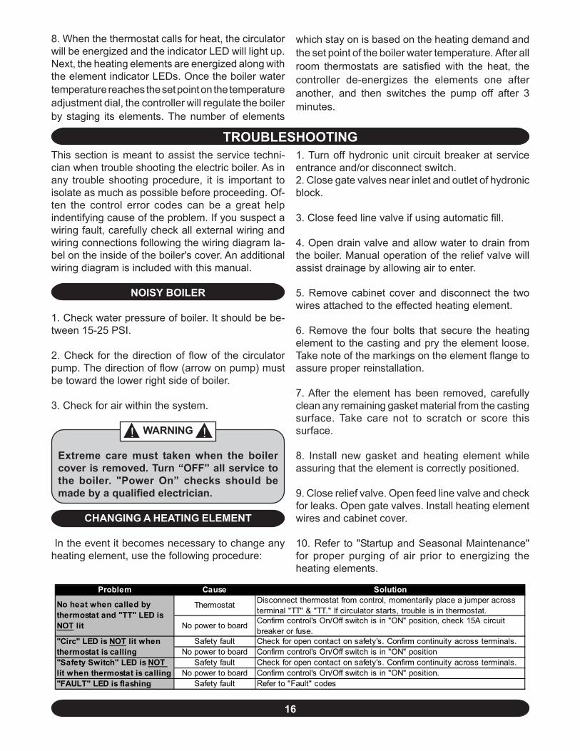
Problem Cause Solution
Thermostat Disconnect thermostat from control, momentarily place a jumper across terminal "TT" & "TT." If circulator starts, trouble is in thermostat.
No power to board Confirm control's On/Off switch is in "ON" position, check 15A circuit breaker or fuse.
Safety fault Check for open contact on safety's. Confirm continuity across terminals. No power to board Confirm control's On/Off switch is in "ON" position
Safety fault Check for open contact on safety's. Confirm continuity across terminals. No power to board Confirm control's On/Off switch is in "ON" position.
"FAULT" LED is flashing Safety fault Refer to "Fault" codes
No heat when called by thermostat and "TT" LED is NOT lit
"Circ" LED is NOT lit when thermostat is calling"Safety Switch" LED is NOT lit when thermostat is calling
TROUBLESHOOTING
which stay on is based on the heating demand andthe set point of the boiler water temperature. After allroom thermostats are satisfied with the heat, thecontroller de-energizes the elements one afteranother, and then switches the pump off after 3minutes.
This section is meant to assist the service techni-cian when trouble shooting the electric boiler. As inany trouble shooting procedure, it is important toisolate as much as possible before proceeding. Of-ten the control error codes can be a great helpindentifying cause of the problem. If you suspect awiring fault, carefully check all external wiring andwiring connections following the wiring diagram la-bel on the inside of the boiler's cover. An additionalwiring diagram is included with this manual.
NOISY BOILER
1. Check water pressure of boiler. It should be be-tween 15-25 PSI.
2. Check for the direction of flow of the circulatorpump. The direction of flow (arrow on pump) mustbe toward the lower right side of boiler.
3. Check for air within the system.
WARNING
Extreme care must taken when the boilercover is removed. Turn “OFF” all service tothe boiler. "Power On” checks should bemade by a qualified electrician.
CHANGING A HEATING ELEMENT
In the event it becomes necessary to change anyheating element, use the following procedure:
1. Turn off hydronic unit circuit breaker at serviceentrance and/or disconnect switch.2. Close gate valves near inlet and outlet of hydronicblock.
3. Close feed line valve if using automatic fill.
4. Open drain valve and allow water to drain fromthe boiler. Manual operation of the relief valve willassist drainage by allowing air to enter.
5. Remove cabinet cover and disconnect the twowires attached to the effected heating element.
6. Remove the four bolts that secure the heatingelement to the casting and pry the element loose.Take note of the markings on the element flange toassure proper reinstallation.
7. After the element has been removed, carefullyclean any remaining gasket material from the castingsurface. Take care not to scratch or score thissurface.
8. Install new gasket and heating element whileassuring that the element is correctly positioned.
9. Close relief valve. Open feed line valve and checkfor leaks. Open gate valves. Install heating elementwires and cabinet cover.
10. Refer to "Startup and Seasonal Maintenance"for proper purging of air prior to energizing theheating elements.
17
! !
Because of its basic design, the hydronic block re-quires only a minimum of periodic maintenance. Thepreventive maintenance tasks described below arenot difficult and when done a yearly basis, will aidthe unit to continue its trouble free operation.
CAUTION
For safety reasons, the main power switch tothe block should be turned off at the mainservice entrance before any work requiringremoval of the cover is done. All work shouldbe performed by qualified service personnelfamiliar with the unit's control systemoperation.
1. This boiler has been designed to provide years oftrouble free performance under normal operatingconditions. However, the owner should conduct ageneral external examination at the beginning ofeach heating season and at mid-heating seatingseason to assure good working performance iscontinued. In addition, a qualified service technicianshould examine at least once every year.
2. Do not store anything against the boiler or allowdirt or debris to accumulate in the area immediatelysurrounding the boiler.
3. Elements will burn out if the boiler is not filled withwater when electrical power is turned on. Do notconnect thermostat wire until system has been filledwith water. Water should be drained out from systemonly when absolutely necessary to make repairs orprevent freeze-up during extended cold weathershutdown.
4. The temperature and pressure gauge on thesystem should be checked frequently. During normaloperating conditions, pressure should be relativelystable throughout the heating season. If pressureunder normal operating conditions consistently risesand falls over a period of time, this can indicate a fillvalve leak, system leak, or compression tankmalfunction. Leaks anywhere in the system mustbe repaired without delay. If any leaks or significantpressure fluctuations are observed, call for serviceimmediately.
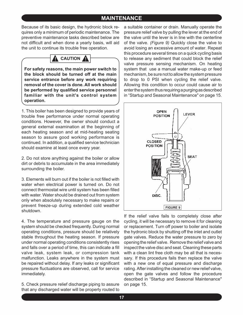
5. Check pressure relief discharge piping to assurethat any discharged water will be properly routed to
FIGURE 9
MAINTENANCEa suitable container or drain. Manually operate thepressure relief valve by pulling the lever at the end ofthe valve until the lever is in line with the centerlineof the valve. (Figure 9) Quickly close the valve toavoid losing an excessive amount of water. Repeatthis procedure several times on a quick cycling basisto release any sediment that could block the reliefvalve pressure sensing mechanism. On heatingsystem that use a manual water make-up or feedmechanism, be sure not to allow the system pressureto drop to 0 PSI when cycling the relief valve.Allowing this condition to occur could cause air toenter the system thus requiring a purging as describedin “Startup and Seasonal Maintenance" on page 15.
If the relief valve fails to completely close aftercycling, it will be necessary to remove it for cleaningor replacement. Turn off power to boiler and isolatethe hydronic block by shutting off the inlet and outletgate valves. Reduce the water pressure to zero byopening the relief valve. Remove the relief valve andinspect the valve disc and seat. Cleaning these partswith a clean lint free cloth may be all that is neces-sary. If this procedure fails then replace the valvewith a new one of equal pressure and dischargerating. After installing the cleaned or new relief valve,open the gate valves and follow the proceduredescribed in “Startup and Seasonal Maintenance"on page 15.
18
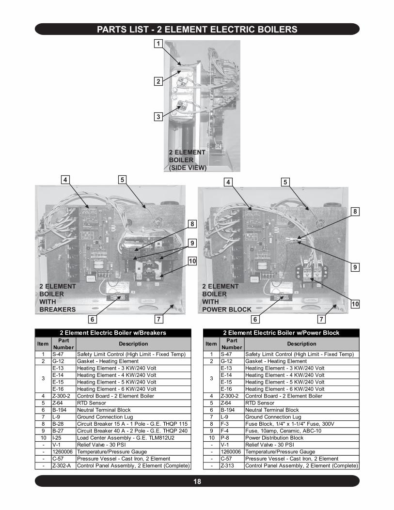
PARTS LIST - 2 ELEMENT ELECTRIC BOILERS
1 S-47 Safety Limit Control (High Limit - Fixed Temp) 1 S-47 Safety Limit Control (High Limit - Fixed Temp)2 G-12 Gasket - Heating Element 2 G-12 Gasket - Heating Element
E-13 Heating Element - 3 KW/240 Volt E-13 Heating Element - 3 KW/240 Volt E-14 Heating Element - 4 KW/240 Volt E-14 Heating Element - 4 KW/240 Volt E-15 Heating Element - 5 KW/240 Volt E-15 Heating Element - 5 KW/240 Volt E-16 Heating Element - 6 KW/240 Volt E-16 Heating Element - 6 KW/240 Volt
4 Z-300-2 Control Board - 2 Element Boiler 4 Z-300-2 Control Board - 2 Element Boiler5 Z-64 RTD Sensor 5 Z-64 RTD Sensor6 B-194 Neutral Terminal Block 6 B-194 Neutral Terminal Block7 L-9 Ground Connection Lug 7 L-9 Ground Connection Lug8 B-28 Circuit Breaker 15 A - 1 Pole - G.E. THQP 115 8 F-3 Fuse Block, 1/4" x 1-1/4" Fuse, 300V9 B-27 Circuit Breaker 40 A - 2 Pole - G.E. THQP 240 9 F-4 Fuse, 10amp, Ceramic, ABC-1010 I-25 Load Center Assembly - G.E. TLM812U2 10 P-8 Power Distribution Block- V-1 Relief Valve - 30 PSI - V-1 Relief Valve - 30 PSI- 1260006 Temperature/Pressure Gauge - 1260006 Temperature/Pressure Gauge- C-57 Pressure Vessel - Cast Iron, 2 Element - C-57 Pressure Vessel - Cast Iron, 2 Element- Z-302-A Control Panel Assembly, 2 Element (Complete) - Z-313 Control Panel Assembly, 2 Element (Complete)
3 3
Item Part Number Description Item
2 Element Electric Boiler w/Breakers 2 Element Electric Boiler w/Power BlockPart
Number Description
2 ELEMENTBOILER(SIDE VIEW)
3
2
1
2 ELEMENTBOILERWITHBREAKERS
4 5
6 7
10
9
8
2 ELEMENTBOILERWITHPOWER BLOCK
6 7
4 5
10
9
8
19
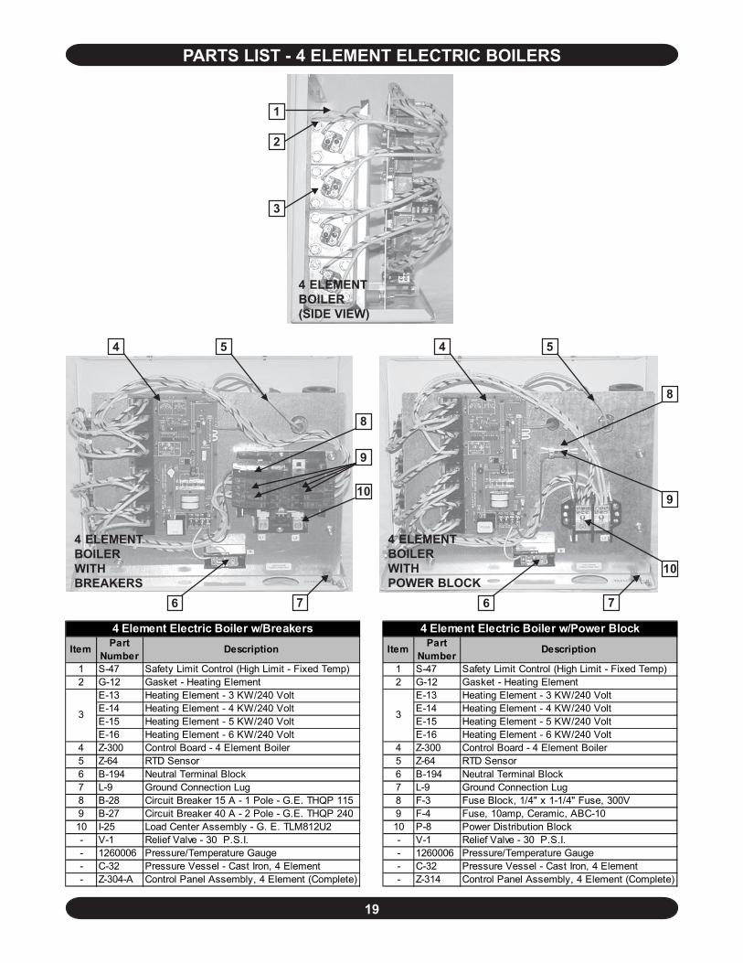
PARTS LIST - 4 ELEMENT ELECTRIC BOILERS
4 ELEMENTBOILER(SIDE VIEW)
2
1
3
1 S-47 Safety Limit Control (High Limit - Fixed Temp) 1 S-47 Safety Limit Control (High Limit - Fixed Temp)2 G-12 Gasket - Heating Element 2 G-12 Gasket - Heating Element
E-13 Heating Element - 3 KW/240 Volt E-13 Heating Element - 3 KW/240 Volt E-14 Heating Element - 4 KW/240 Volt E-14 Heating Element - 4 KW/240 Volt E-15 Heating Element - 5 KW/240 Volt E-15 Heating Element - 5 KW/240 Volt E-16 Heating Element - 6 KW/240 Volt E-16 Heating Element - 6 KW/240 Volt
4 Z-300 Control Board - 4 Element Boiler 4 Z-300 Control Board - 4 Element Boiler5 Z-64 RTD Sensor 5 Z-64 RTD Sensor6 B-194 Neutral Terminal Block 6 B-194 Neutral Terminal Block7 L-9 Ground Connection Lug 7 L-9 Ground Connection Lug8 B-28 Circuit Breaker 15 A - 1 Pole - G.E. THQP 115 8 F-3 Fuse Block, 1/4" x 1-1/4" Fuse, 300V9 B-27 Circuit Breaker 40 A - 2 Pole - G.E. THQP 240 9 F-4 Fuse, 10amp, Ceramic, ABC-1010 I-25 Load Center Assembly - G. E. TLM812U2 10 P-8 Power Distribution Block- V-1 Relief Valve - 30 P.S.I. - V-1 Relief Valve - 30 P.S.I.- 1260006 Pressure/Temperature Gauge - 1260006 Pressure/Temperature Gauge- C-32 Pressure Vessel - Cast Iron, 4 Element - C-32 Pressure Vessel - Cast Iron, 4 Element- Z-304-A Control Panel Assembly, 4 Element (Complete) - Z-314 Control Panel Assembly, 4 Element (Complete)
3 3
Item Part Number Description Item
4 Element Electric Boiler w/Breakers 4 Element Electric Boiler w/Power BlockPart
Number Description
4 ELEMENTBOILERWITHBREAKERS
4 5
6 7
10
9
8
4 ELEMENTBOILERWITHPOWER BLOCK
4 5
6 7
10
9
8
20
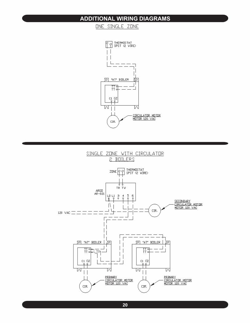
ADDITIONAL WIRING DIAGRAMS
21
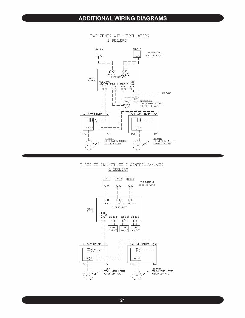
ADDITIONAL WIRING DIAGRAMS
22
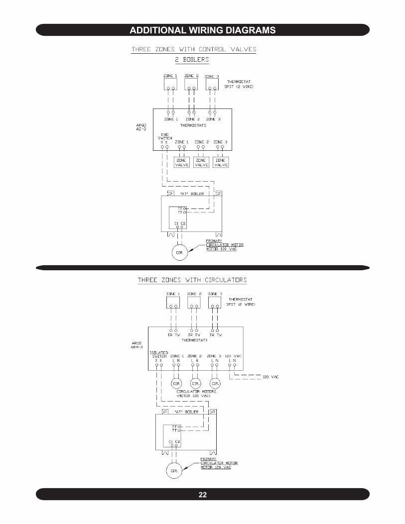
ADDITIONAL WIRING DIAGRAMS
23
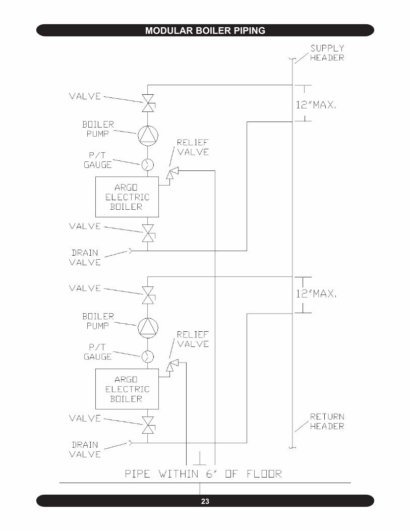
MODULAR BOILER PIPING
24
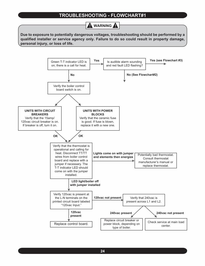
TROUBLESHOOTING - FLOWCHART#1
! !WARNING
Due to exposure to potentially dangerous voltages, troubleshooting should be performed by aqualified installer or service agency only. Failure to do so could result in property damage,personal injury, or loss of life.
Green T-T indicator LED ison; there is a call for heat.
Verify the boiler controlboard switch is on.
Potentially bad thermostat.Consult thermostat
manufacturer’s manual orreplace thermostat.
Verify 120vac is present atthe L-N terminals on the
printed circuit board labeled“120vac Input.”
Replace control board.
No
UNITS WITH POWERBLOCKS
Verify that the ceramic fuseis good. If fuse is blown,
replace it with a new one.
UNITS WITH CIRCUITBREAKERS
Verify that the 15amp/120vac circuit breaker is on.
If breaker is off, turn it on.
Verify that the thermostat isoperational and calling for
heat. Disconnect TT/TTwires from boiler controlboard and replace with ajumper if necessary. TheT-T indicator LED shouldcome on with the jumper
installed.
OK OK
Lights come on with jumperand elements then energize
Replace circuit breaker orpower block, depending on
type of boiler.
Check service at main loadcenter.
Verify that 240vac ispresent across L1 and L2.
LED light/boiler offwith jumper installed
120vac not present
120vacpresent
240vac not present240vac present
Yes Is audible alarm soundingand red fault LED flashing?
Yes (see Flowchart #3)
No (See Flowchart#2)
25
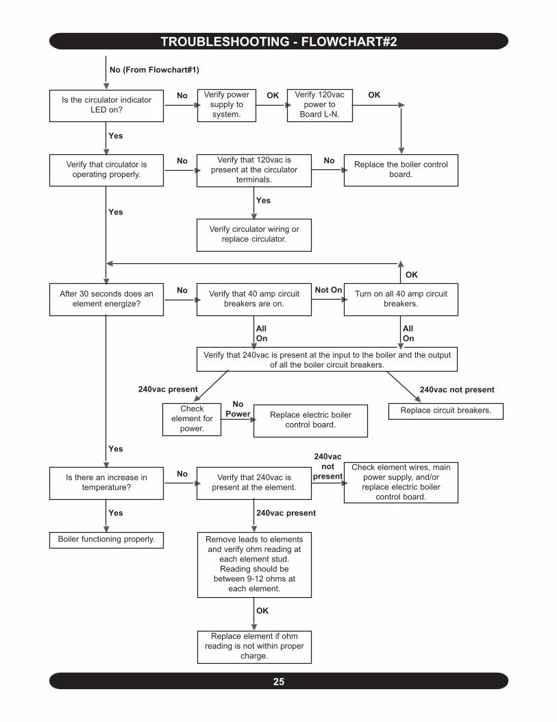
TROUBLESHOOTING - FLOWCHART#2
Is the circulator indicatorLED on?
No (From Flowchart#1)
Yes
NoVerify that circulator isoperating properly.
Verify that 120vac ispresent at the circulator
terminals.
No Replace the boiler controlboard.
Yes
Verify circulator wiring orreplace circulator.
Yes
NoAfter 30 seconds does anelement energize?
Not On Turn on all 40 amp circuitbreakers.
Verify that 40 amp circuitbreakers are on.
AllOn
Verify that 240vac is present at the input to the boiler and the outputof all the boiler circuit breakers.
240vac not present240vac present
Replace circuit breakers.
Yes
NoIs there an increase intemperature?
240vacnot
presentVerify that 240vac ispresent at the element.
Check element wires, mainpower supply, and/orreplace electric boiler
control board.
Yes
Boiler functioning properly. Remove leads to elementsand verify ohm reading at
each element stud.Reading should be
between 9-12 ohms ateach element.
OK
240vac present
Replace element if ohmreading is not within proper
charge.
No Verify powersupply tosystem.
OK Verify 120vacpower to
Board L-N.
OK
OK
AllOn
Checkelement for
power.
NoPower Replace electric boiler
control board.
26
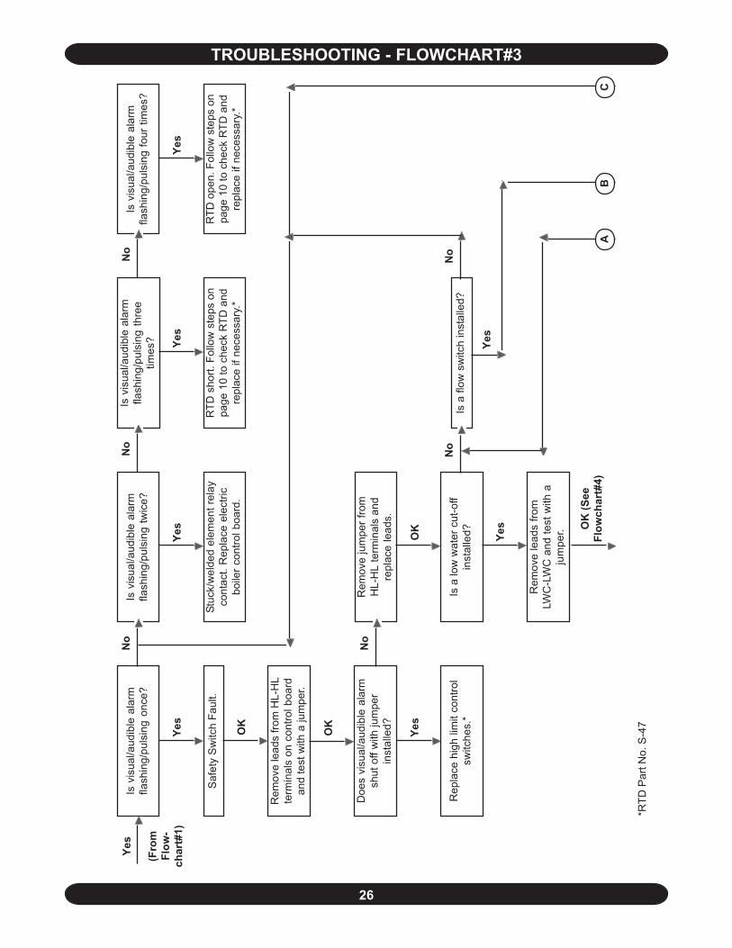
TROUBLESHOOTING - FLOWCHART#3
Is v
isua
l/aud
ible
ala
rmfla
shin
g/pu
lsin
g on
ce?
Is a
low
wat
er c
ut-o
ffin
stal
led?
Saf
ety
Sw
itch
Faul
t.
Rem
ove
lead
s fro
m H
L-H
Lte
rmin
als
on c
ontro
l boa
rdan
d te
st w
ith a
jum
per.
Doe
s vi
sual
/aud
ible
ala
rmsh
ut o
ff w
ith ju
mpe
rin
stal
led?
Is v
isua
l/aud
ible
ala
rmfla
shin
g/pu
lsin
g th
ree
times
?
Is v
isua
l/aud
ible
ala
rmfla
shin
g/pu
lsin
g fo
ur ti
mes
?Is
vis
ual/a
udib
le a
larm
flash
ing/
puls
ing
twic
e?
Stuc
k/w
elde
d el
emen
t rel
ayco
ntac
t. R
epla
ce e
lect
ricbo
iler c
ontro
l boa
rd.
RTD
sho
rt. F
ollo
w s
teps
on
page
10
to c
heck
RTD
and
repl
ace
if ne
cess
ary.
*
RTD
ope
n. F
ollo
w s
teps
on
page
10
to c
heck
RTD
and
repl
ace
if ne
cess
ary.
*
Yes
Yes
Yes
Yes
No
No
No
Rem
ove
jum
per f
rom
HL-
HL
term
inal
s an
dre
plac
e le
ads.
No
OK
OK
Yes
OK O
K (S
eeFl
owch
art#
4)
Rem
ove
lead
s fro
mLW
C-L
WC
and
test
with
aju
mpe
r.
Rep
lace
hig
h lim
it co
ntro
lsw
itche
s.*
Is a
flow
sw
itch
inst
alle
d?N
oN
o
Yes
Yes
(Fro
mFl
ow-
char
t#1)
Yes
AB
C
*RTD
Par
t No.
S-4
7
27
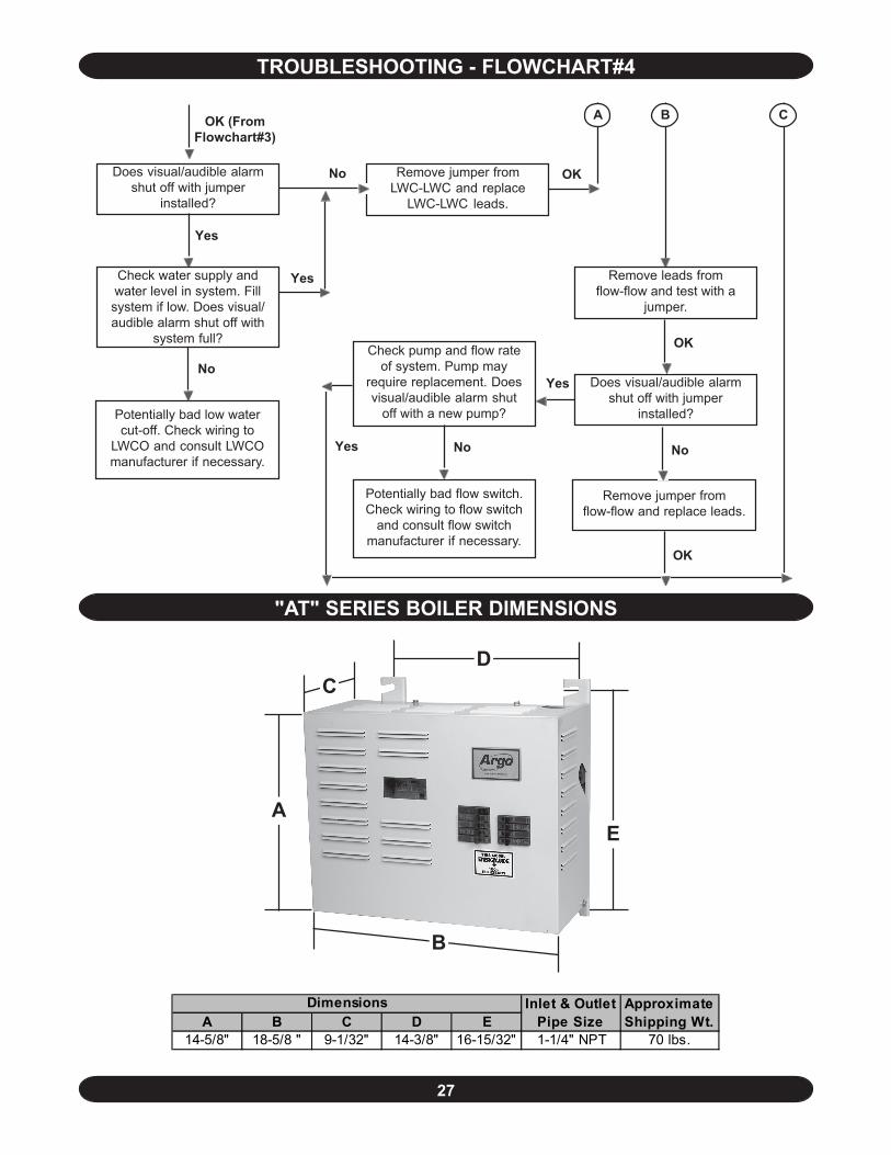
TROUBLESHOOTING - FLOWCHART#4
"AT" SERIES BOILER DIMENSIONS
A B C D E14-5/8" 18-5/8 " 9-1/32" 14-3/8" 16-15/32" 1-1/4" NPT 70 lbs.
Dimensions Inlet & Outlet Pipe Size
Approximate Shipping Wt.
A
B
CD
E
Remove jumper fromLWC-LWC and replace
LWC-LWC leads.
Does visual/audible alarmshut off with jumper
installed?
OK
Check water supply andwater level in system. Fillsystem if low. Does visual/audible alarm shut off with
system full?
Remove leads fromflow-flow and test with a
jumper.
Does visual/audible alarmshut off with jumper
installed?
OK
OK (FromFlowchart#3)
Yes
A
No
B
Remove jumper fromflow-flow and replace leads.
No
OK
C
Potentially bad flow switch.Check wiring to flow switch
and consult flow switchmanufacturer if necessary.
Yes
Potentially bad low watercut-off. Check wiring to
LWCO and consult LWCOmanufacturer if necessary.
NoCheck pump and flow rate
of system. Pump mayrequire replacement. Doesvisual/audible alarm shut
off with a new pump?
No
Yes
Yes
28
HOMEOWNER'S REFERENCE TABLE
Model Number: _____________________________________________
Serial Number: _____________________________________________
Date Installed: ______________________________________________
Contractor:_________________________________________________
Contact: ___________________________________________________
Address: ___________________________________________________
__________________________________________________________
Telephone Number: _________________________________________
After Hours Number:_________________________________________
If different from Installation Contractor:
Service Tech: _______________________________________________
Telephone Number: _________________________________________
After Hours Number:_________________________________________