Embed Size (px)
Citation preview
ASTA Low Energy Absorber Thermal Analysis
Version 5, June 08 2012C. Baffes and I. Rakhno
Beam Doc DB ID: Beams-doc-4063
Design review held on Jan 11 2012: Updates relative to that review are shown in green.
Re-analysis at 55MeV beam energy completed June 08 2012: Results documented in Appendix 2.

ASTA LE Absorber Thermal Analysis 2
Scope and Review Charge
• Review Charge: please review the configuration and thermal analysis of the low energy dumps and assess whether
• Absorber configuration is appropriate• Analysis assumptions, method, and results are reasonable• System is ready to move on to detailed mechanical design
• Included in the scope of this review• Configuration of the ASTA Low Energy Dumps• Thermal analysis methodology and results
• Excluded from the scope of this review• Radiation analysis and shielding assessment
Jan 11 2012

ASTA LE Absorber Thermal Analysis 3
ASTA Low Energy Beam Absorber AnalysisOutline
•System Overview and Configuration• MARS Analysis Inputs• Material and Fluid Analysis Inputs• Thermal Model• Steady State Analysis and Beginning of Life Performance• Radiation Damage and End of Life Performance• Pulse Transient• System Transient Analyses• Conclusions• Appendix 1 – Reduced Intensity Cases. • Appendix 2 – 55MeV Analysis
Jan 11 2012
4
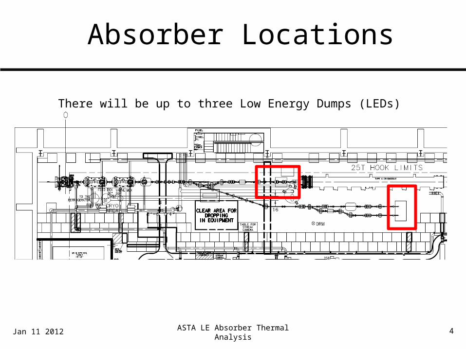
Absorber Locations
Jan 11 2012 ASTA LE Absorber Thermal Analysis
There will be up to three Low Energy Dumps (LEDs)
ASTA LE Absorber Thermal Analysis 5
Beam Parameters
• Beam Parameterso electron beam at 50 MeV, 3.33 nC/buncho 6.24E13 e-/pulse, 5 pulses/s, 3.12 E14 electrons/so Pulse duration 1mso 2.5kW average beam power
• Absorber shall be capable of accepting beam continuously (i.e. steady state operation)
Jan 11 2012

6
Packaging Constraints
LED 1 must clear beamline components, particularly radia beam cross X126. Cross at X129 will likely be rotated away from the LED (about the beam pipe) and does not pose a hard constraint
Approximate envelope for proposed implementation

7
Absorber Configuration(Section View)
32”
43”
32”
Beam
Jan 11 2012 ASTA LE Absorber Thermal Analysis
Tunnel floor
1” airgap to facilitate LED adjustment

ASTA LE Absorber Thermal Analysis 8
Absorber Configuration
Jan 11 2012

9
Absorber Core
10
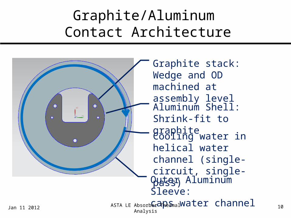
Graphite/Aluminum Contact Architecture
Graphite stack: Wedge and OD machined at assembly level
Aluminum Shell:Shrink-fit to graphite
Cooling water in helical water channel (single-circuit, single-pass)
Outer Aluminum Sleeve:caps water channel
Jan 11 2012 ASTA LE Absorber Thermal Analysis

11
Helical Water Channel
Helical Water ChannelGenerated on screw machine0.3” wide X 0.15” deep1” Pitch
Inlet:Short cross-hole intersects channel-start feature
Outlet:Long gun-drilled cross-hole intersects channel-end feature
ASTA LE Absorber Thermal Analysis 12
ASTA Low Energy Beam Absorber AnalysisOutline
•System Overview and Configuration• MARS Analysis Inputs• Material and Fluid Analysis Inputs• Thermal Model• Steady State Analysis and Beginning of Life Performance• Radiation Damage and End of Life Performance• Pulse Transient• System Transient Analyses• Conclusions
Jan 11 2012

13
Data Processing Approach
• Step 1: I. Rakhno produces MARS results• Step 2: Process MARS results in Excel
o Tabulate X, Y, Z and heat generation for each MARS element• Step 3: Generate mechanical FEA models in NX/Ansys
o Symmetric half-model used for all analyseso Tabulate FEA mesh nodal and element XYZ locations
• Step 4: Interpolate MARS results onto FEA mesh in Matlabo Use MARS radiation damage estimates to assign material properties o Map heat generation results from MARS mesh onto arbitrary FEA mesho Calculate heat generation at each FEA elemento Generate Ansys text input using BFE/HGEN
• Step 5: Run Ansys to recover temperatures
Jan 11 2012 ASTA LE Absorber Thermal Analysis
14
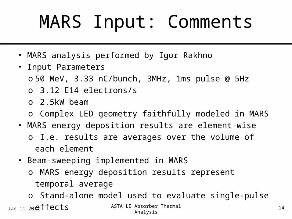
MARS Input: Comments
• MARS analysis performed by Igor Rakhno• Input Parameters
o 50 MeV, 3.33 nC/bunch, 3MHz, 1ms pulse @ 5Hzo 3.12 E14 electrons/so 2.5kW beamo Complex LED geometry faithfully modeled in MARS
• MARS energy deposition results are element-wiseo I.e. results are averages over the volume of each element
• Beam-sweeping implemented in MARSo MARS energy deposition results represent temporal averageo Stand-alone model used to evaluate single-pulse effects
Jan 11 2012 ASTA LE Absorber Thermal Analysis
15
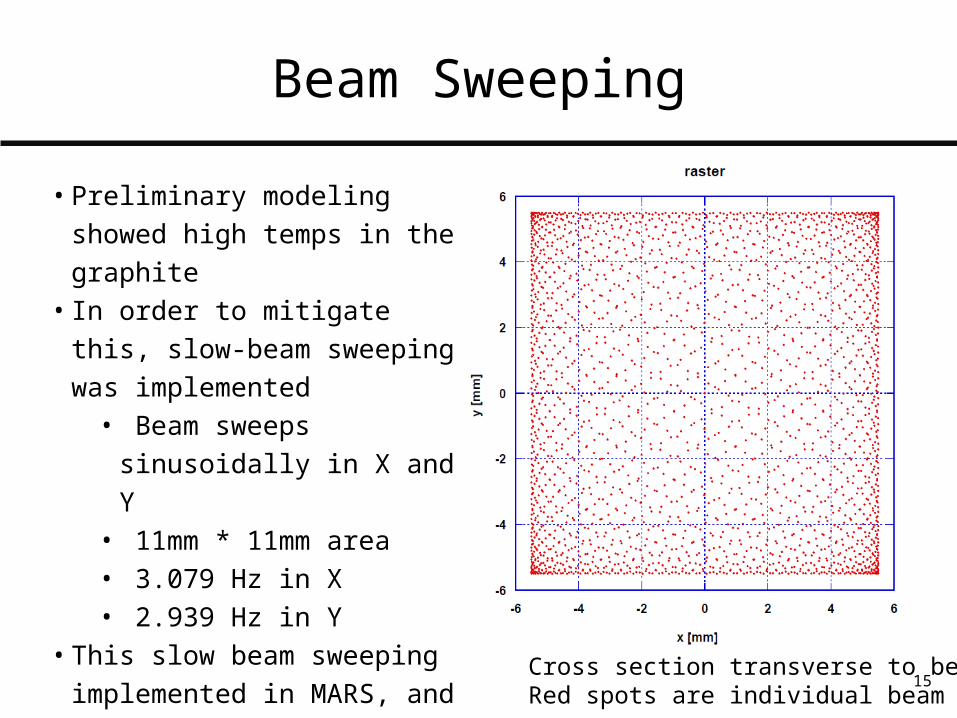
Beam Sweeping
Cross section transverse to beamRed spots are individual beam pulses
• Preliminary modeling showed high temps in the graphite
• In order to mitigate this, slow-beam sweeping was implemented
• Beam sweeps sinusoidally in X and Y
• 11mm * 11mm area• 3.079 Hz in X• 2.939 Hz in Y
• This slow beam sweeping implemented in MARS, and therefore assumed in all steady-state analyses
16
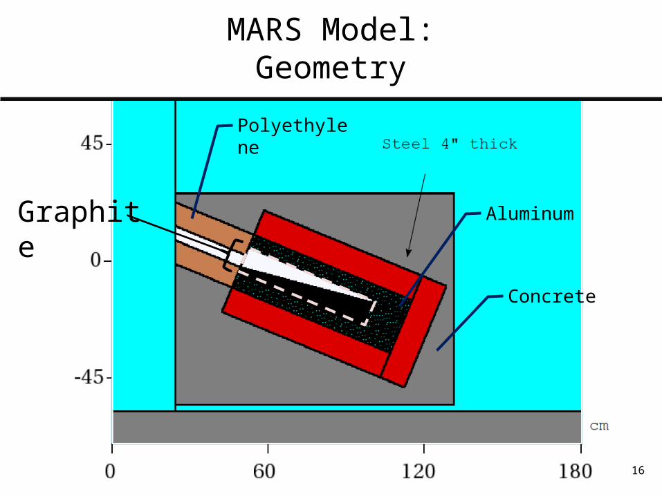
MARS Model:Geometry
Graphite
Polyethylene
Aluminum
Concrete

17
MARS Results:Energy Deposition (mW/g)
Graphite

ASTA LE Absorber Thermal Analysis 18
MARS ResultsHeat Generation (W/m3): log color scale
Graphite
Max: 1.22E8 W/m3
Jan 11 2012
Al10n

ASTA LE Absorber Thermal Analysis 19
ASTA Low Energy Beam Absorber AnalysisOutline
•System Overview and Configuration• MARS Analysis Inputs• Material and Fluid Analysis Inputs• Thermal Model• Steady State Analysis and Beginning of Life Performance• Radiation Damage and End of Life Performance• Pulse Transient• System Transient Analyses• Conclusions
Jan 11 2012

20
Material Selection
• For the absorber core, we will use Toyo Tanso IG-110 • Quasi-isotropic Nuclear-grade graphite• Spare material on hand from high energy absorber build• Material properties modeled as a function of temperature
and radiation-induced damage (see next slide)
• For the Aluminum Shell, we will use AL-6061 T6• Readily available in the required forms• Temperature dependant material properties per MIL-
HDBK-5HJan 11 2012 ASTA LE Absorber Thermal Analysis
ASTA LE Absorber Thermal Analysis 21
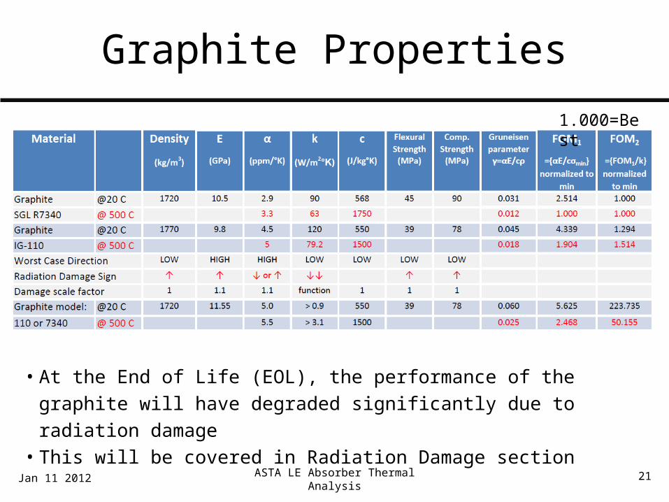
Graphite Properties1.000=Best
• At the End of Life (EOL), the performance of the graphite will have degraded significantly due to radiation damage
• This will be covered in Radiation Damage section
Jan 11 2012
22
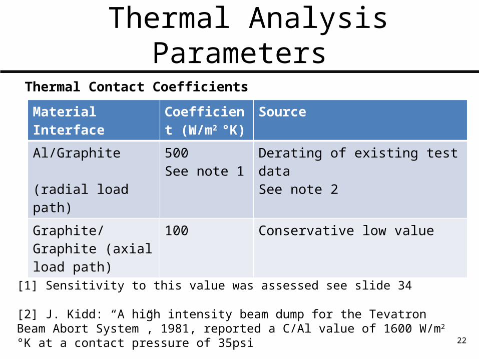
Thermal Analysis Parameters
MaterialInterface
Coefficient (W/m2 °K)
Source
Al/Graphite (radial load path)
500See note 1
Derating of existing test dataSee note 2
Graphite/Graphite (axial load path)
100 Conservative low value
Thermal Contact Coefficients
[1] Sensitivity to this value was assessed see slide 34
[2] J. Kidd: “A high intensity beam dump for the Tevatron Beam Abort System”, 1981, reported a C/Al value of 1600 W/m2 °K at a contact pressure of 35psi

23
Thermal Analysis Parameters
Cooling water convection coefficient:
h=12,100 W/m2 °K
This is based on an empirical correlation calculation with the following key assumptions and parameters: • Single channel/single pass system • Full 2.5kW beam power is rejected through cooling water • Design cooling water temperature rise ΔT= 10 °K• Flow rate of 0.06 l/s (1 gallon/minute)• Internal flow in rectangular 0.3”X 0.15” channels• Fully developed turbulent flow: Re=17,400• Gnielinski-Petukhov empirical correlation
Jan 11 2012 ASTA LE Absorber Thermal Analysis

ASTA LE Absorber Thermal Analysis 24
ASTA Low Energy Beam Absorber AnalysisOutline
•System Overview and Configuration• MARS Analysis Inputs• Material and Fluid Analysis Inputs• Thermal Model• Steady State Analysis and Beginning of Life Performance• Radiation Damage and End of Life Performance• Pulse Transient• System Transient Analyses• Conclusions
Jan 11 2012
ASTA LE Absorber Thermal Analysis 25
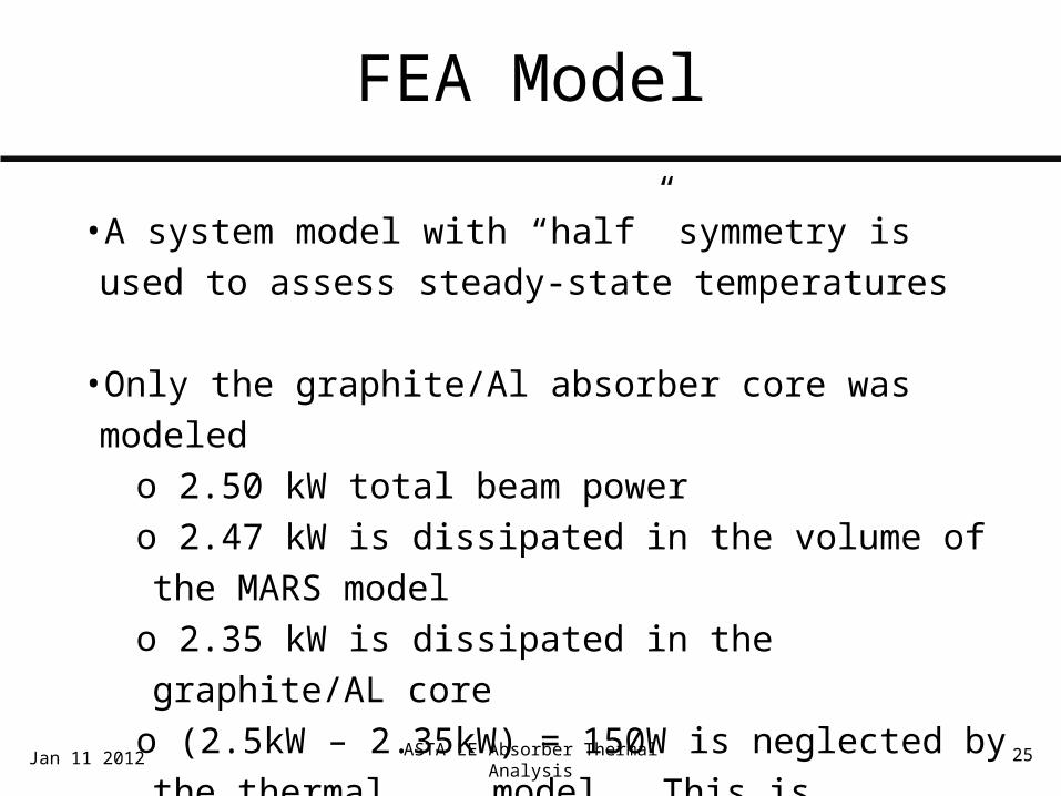
FEA Model
•A system model with “half” symmetry is used to assess steady-state temperatures
•Only the graphite/Al absorber core was modeledo 2.50 kW total beam powero 2.47 kW is dissipated in the volume of the MARS modelo 2.35 kW is dissipated in the graphite/AL core o (2.5kW – 2.35kW) = 150W is neglected by the thermal
model. This is acceptable
Jan 11 2012
ASTA LE Absorber Thermal Analysis 26
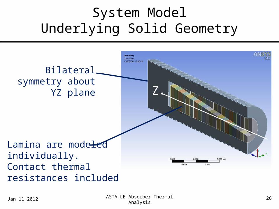
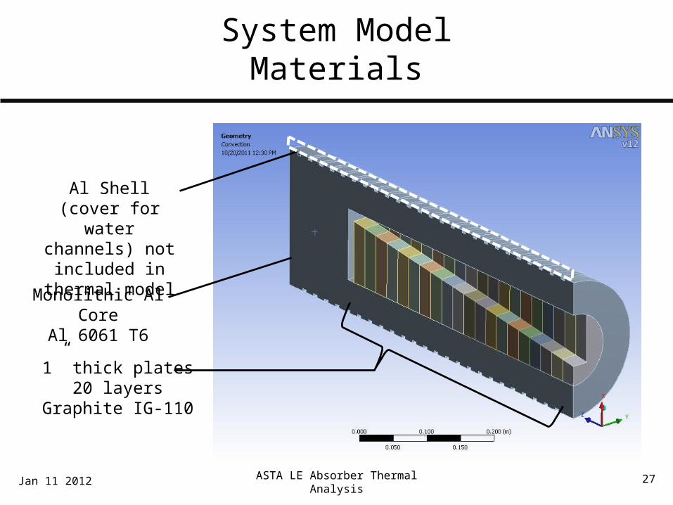
System ModelUnderlying Solid Geometry
Lamina are modeled individually. Contact thermal resistances included
Bilateral symmetry about YZ plane
Jan 11 2012
Z
27
System ModelMaterials
1” thick plates20 layers
Graphite IG-110
Al Shell (cover for water channels) not included in thermal
model
Monolithic Al CoreAl 6061 T6
Jan 11 2012 ASTA LE Absorber Thermal Analysis

28
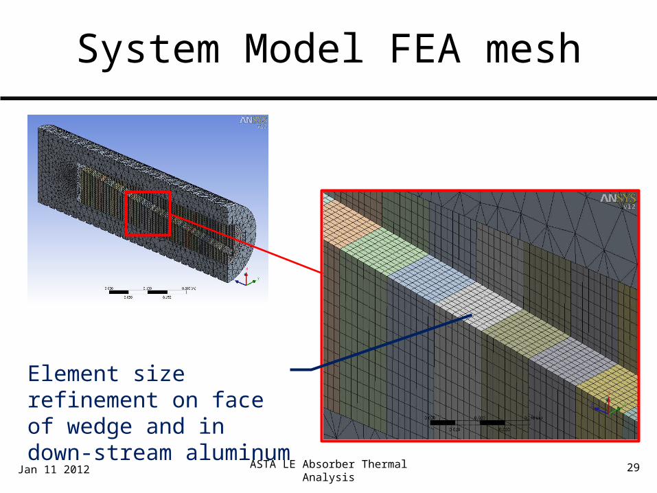
System Model FEA mesh
ASTA LE Absorber Thermal Analysis 29
System Model FEA mesh
Element size refinement on face of wedge and in down-stream aluminum
Jan 11 2012
30
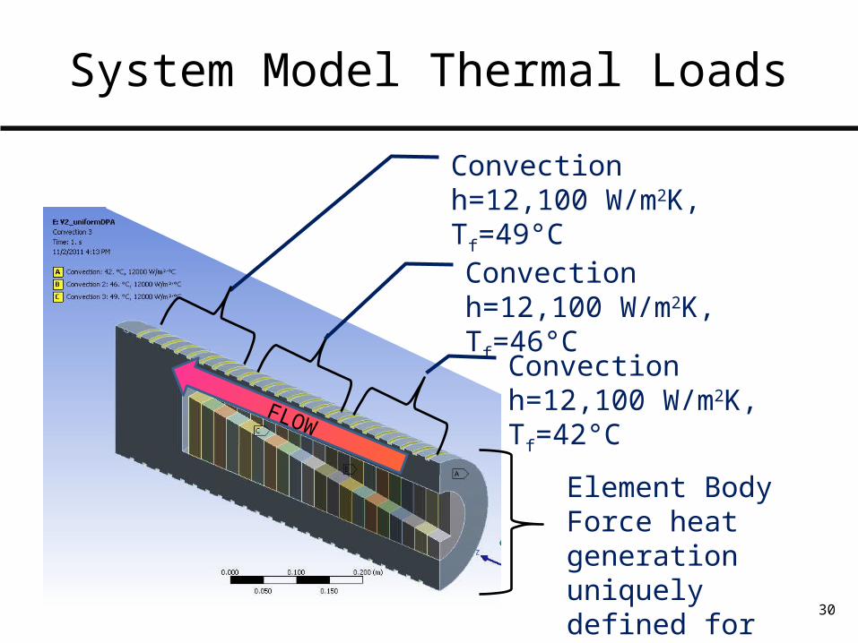
System Model Thermal Loads
Convectionh=12,100 W/m2K, Tf=49°C
FLOW
Convectionh=12,100 W/m2K, Tf=46°C
Convectionh=12,100 W/m2K, Tf=42°C
Element Body Force heat generation uniquely defined for each element

ASTA LE Absorber Thermal Analysis 31
ASTA Low Energy Beam Absorber AnalysisOutline
•System Overview and Configuration• MARS Analysis Inputs• Material and Fluid Analysis Inputs• Thermal Model• Steady State Analysis and Beginning of Life Performance• Radiation Damage and End of Life Performance• Pulse Transient• System Transient Analyses• Conclusions
Jan 11 2012
ASTA LE Absorber Thermal Analysis 32
Steady State Analyses
• The steady state thermal analyses neglect the pulsed nature of the energy deposition, and assume constant and continuous beam power
• We use two sets of graphite properties:• Beginning of Life (BOL) – graphite properties not degraded by radiation
damage (but still fully temperature dependant)• End of Life (EOL) – graphite damage categorized in bins, corresponding
degraded material properties mapped onto the FEA mesh• EOL analyses are presented in the next section
Jan 11 2012

ASTA LE Absorber Thermal Analysis 33
System Model Steady StateMaximum temperature in graphite and system
Jan 11 2012
Max Temp. in Graphite = 268°C
Beam
Key inputs: -Graphite/Al thermal contact 500 W/m2K
-Swept beam (i.e. temperatures represent temporal average)
-Graphite with undamaged BOL material properties

ASTA LE Absorber Thermal Analysis 34
System Model Steady StateMaximum temperature in Aluminum
Jan 11 2012
Max Temp. in Al = 58°C<16°C above cooling water temp
Beam
Key inputs: -Graphite/Al thermal contact 500 W/m2K
-Swept beam (i.e. temperatures represent temporal average)
-Graphite with undamaged BOL material properties

35
Thermal Contact Sensitivity
For good performance, need to achieve contact conductance > 250W/m2K
500 W/m2K used for all analysis

36
Thermal Contact Sensitivity(updated 7-Feb-2012)
• Given the acknowledged sensitivity to C/Al thermal contact, the reviewers recommended calculating a worst-case thermal contact by looking at conduction across a small (unintentional) air gap.
• The contact thermal conductance for a 30um air gap is given as:
C = kair/tgap = (.0263 W/m K) / (0.00003m) = 876 W/m2 K
• So, the assumed contact thermal conductance of 500 W/m2 K is quite conservative. We can expect to be on the “flat” part of the curve shown on the previous slide
Updated: Feb 07 2012 ASTA LE Absorber Thermal Analysis

37
Steady-State Thermal Analysis Conclusions
• Thermal design appears to be acceptable at BOL steady state
• System is sensitive to graphite/aluminum contact thermal conductance
• Even if we have a small air gap, we should achieve acceptable contact
• Testing planned in support of beam exit window design should help us to build confidence in the modeled values
Updated: Feb 07 2012 ASTA LE Absorber Thermal Analysis

ASTA LE Absorber Thermal Analysis 38
ASTA Low Energy Beam Absorber AnalysisOutline
•System Overview and Configuration• MARS Analysis Inputs• Material and Fluid Analysis Inputs• Thermal Model• Steady State Analysis and Beginning of Life Performance• Radiation Damage and End of Life Performance• Pulse Transient• System Transient Analyses• Conclusions
Jan 11 2012

39
Radiation Damage
• After exposure to radiation, the graphite core may undergo variation in mechanical properties and loss of material
• Changes in mechanical properties have been investigated in the analysis, and can be accommodated by the current design•Will limit lifetime of absorbers to 1.4E21 electrons
(~4 calendar years at full intensity). More on this later• Low energy absorbers can be replaced, so this is acceptable
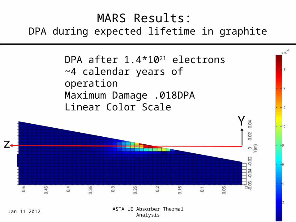
• Damage limit benchmarks:• 0.68 DPA – ~10% material loss seen in NuMI graphite• 0.25 DPA – limit established for ASTA high energy absorbers• 0.018 DPA – Predicted LED damage after 1.4E21 e-• 0.01 DPA – significant loss of thermal conductivity

40
Duty Cycle
• Mike Church defined the following duty cycle:
• Given that LED will operate in air, surface temperatures in graphite must be limited < ~500°C• Analysis of damaged LED was iterated until temperatures at End-of-Life
approached 400°C (leaving some headroom for pulse effects). This occurred at 1.4E21 electrons, or about 4 calendar years of operation
Parameter Value Comments
Nominal Intensity 3.12E14 electrons/s Design particle flux
Operation Fraction (up time)
0.7 10 months/year6 days/week
Dump Fraction 0.1 Fraction of beam to any one LED
Intensity Fraction 0.5 (Average intensity) / (design intensity
Yearly fluence, per LED 3.44E20 electrons/year Design value for LED
41
MARS Results: DPA during expected lifetime in graphite
Y
z
DPA after 1.4*1021 electrons~4 calendar years of operationMaximum Damage .018DPALinear Color Scale
Jan 11 2012 ASTA LE Absorber Thermal Analysis

42
MARS Results: DPA during expected lifetime in graphite
Y
z
DPA after 1.4*1021 electrons~4 calendar years of operationMaximum Damage .018DPALogarithmic Color Scale
10n
Jan 11 2012 ASTA LE Absorber Thermal Analysis

43
Radiation Effects: Thermal Conductivity Reduction
• Irradiation-induced defects collect at the crystal boundaries, and interrupt conduction between crystals.
•This causes the thermal conductivity to assume a complex radiation and temperature dependency.
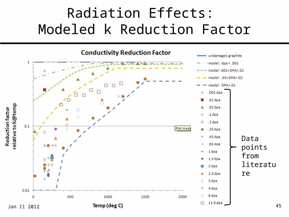
•Data exist in the literature, but are not entirely consistentoEffect begins at low damage levels: ~0.001 dpaoEffect is less pronounced at high temperatures (material is able to self-
anneal to some extent)
•As such, we’ll use an envelope approach to conservatively bound the conductivity at all temperatures and all radiation levels.
o Define four damage levels enveloping the datao Define k(T) for each damage levelo Comparatively minor variations in E, α are also accounted foro In the FEA, assign each element to one of these damage bins

44
Radiation Effects: Example Data
Jan 11 2012
45
Radiation Effects: Modeled k Reduction Factor
Jan 11 2012
Data points from literature

46
Damage Mapping on FEA model
•As shown on the previous slide, discrete materials were defined with thermal conductivity as a function of damage and temperature.
• MARS damage estimates were mapped onto the FEA mesh. Individual elements were “binned” by damage level.• Damage mapped from iteratively-determined end of life case, i.e. after fluence of 1.4E21 electrons
• Materials were assigned to FEA elements on an element-by-element basis, based upon the MARS damage estimate
Jan 11 2012 ASTA LE Absorber Thermal Analysis

Mapping of k Reductionat EOL on Graphite Core
Material 204.01< Damage <.02 dpa
Material 203.001< Damage <.01 dpa
Material 202.0001< Damage <.001 dpa
Material 201Damage <.0001 dpa
Assumed to be undamaged
Z
47
48
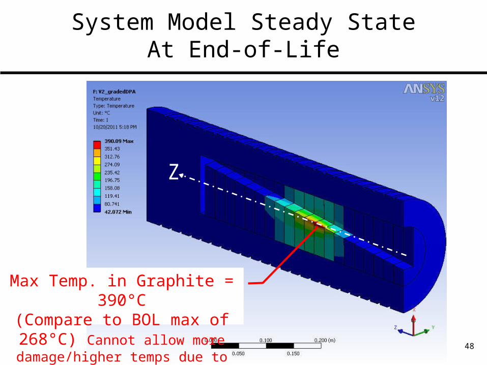
Max Temp. in Graphite = 390°C(Compare to BOL max of 268°C)
Cannot allow more damage/higher temps due to risk of graphite oxidation
System Model Steady StateAt End-of-Life
Z
ASTA LE Absorber Thermal Analysis 49
ASTA Low Energy Beam Absorber AnalysisOutline
•System Overview and Configuration• MARS Analysis Inputs• Material and Fluid Analysis Inputs• Thermal Model• Steady State Analysis and Beginning of Life Performance• Radiation Damage and End of Life Performance• Pulse Transient• System Transient Analyses• Conclusions
Jan 11 2012
50
Pulse Transient
• Steady-state thermal results are a temporal and spatial average• Temporal average because we normalize per-electron
results to e-/s particle rate• Spatial average because beam rastering is implemented in
MARS before thermal analysis
• In reality, energy deposition occurs in discreet pulses• 1ms pulse @5Hz, 6.24E13 e-/pulse
• Beam is essentially stationary during a pulse: sweeping at 3Hz results in negligible beam motion on the 1ms time scale
Jan 11 2012 ASTA LE Absorber Thermal Analysis

51
Pulse Transient
• Each pulse will then create a quasi-instantaneous temperature rise where it strikes the absorber
• The next pulse will affect a different area, due to the beam sweeping
• Neglecting conduction during the pulse, we can estimate the magnitude of the temperature rise
• This temperature rise will add linearly to steady-state temperatures we have calculated
Jan 11 2012 ASTA LE Absorber Thermal Analysis
52
Beam Size vs. MARS Cell Size
• The MARS model was re-run with a non-swept beam to capture single pulse effects (This calculation was re-visited after the review, and expanded to various reduced intensity scenarios. See appendix 1 for this information)
• MARS cell cross section (in a plane whose normal is ~parallel to beam direction) is 5mm X 5mm
• This is small compared to the swept beam area of 11mm X 11mm• This is large compared to the minimum beam size, particularly in the x
direction (σx=0.3mm). So near incidence, before the beam has fanned out, energy deposition will occur over a volume smaller than a MARS cell
• MARS results average energy deposition over the full volume of each element, “smearing” these local effects
Jan 11 2012 ASTA LE Absorber Thermal Analysis

53
Beam Size vs. MARS Cell Size
Beam Centerline
Beam 1σ envelope size - Y
Beam 1σ envelope size – X:Small compared to MARS cell
5mm

54
Beam Size vs. MARS Cell Size
• A simplified MARS study was done to determine how to scale maximum energy deposition results. The following relationship was confirmed
For cells near beam incidence whose size is >> beam size
[Volumetric-average Energy deposition reported for cell (W/m3)] is proportional to [1/Cell Volume]
• In cases where the beam size is comparable to the cell size, it is necessary to calculate how much of the beam is hitting a given cell and apply compensation appropriately.
Jan 11 2012 ASTA LE Absorber Thermal Analysis

55
Beam Size vs. MARS Cell Size
• So, we can use the following method to reconstruct the true peak value of the energy deposition
• Find MARS cells near beam incidence, before beam has fanned out• Assume (conservatively) that beam size is unaffected as it travels through
these first few cells• Determine area-fraction of the beam that passes through the given cells• Calculate the total energy deposited by the full Gaussian beam near
incidence• Calculate the peak energy deposition of the Gaussian distribution• Calculate instantaneous temperature rise
Jan 11 2012 ASTA LE Absorber Thermal Analysis
56
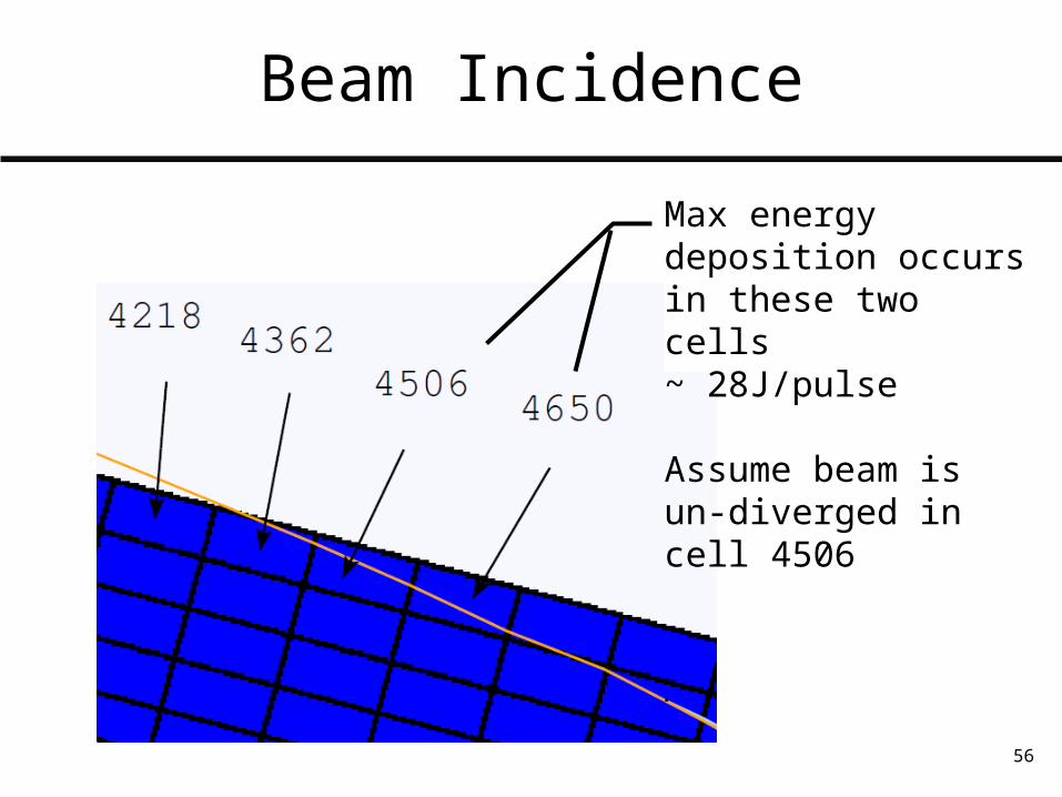
Beam Incidence
Max energy deposition occurs in these two cells~ 28J/pulse
Assume beam is un-diverged in cell 4506
57
Beam Profile at Incidence
4506
Ybeam
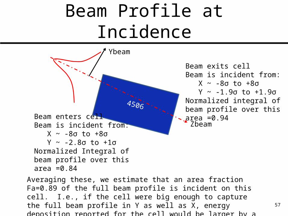
Beam enters cellBeam is incident from: X ~ -8σ to +8σ Y ~ -2.8σ to +1σNormalized Integral of beam profile over this area =0.84
Beam exits cellBeam is incident from: X ~ -8σ to +8σ Y ~ -1.9σ to +1.9σNormalized integral of beam profile over this area =0.94
Zbeam
Averaging these, we estimate that an area fraction Fa=0.89 of the full beam profile is incident on this cell. I.e., if the cell were big enough to capture the full beam profile in Y as well as X, energy deposition reported for the cell would be larger by a factor of (1/0.89)

58
Energy Deposition at Beam Incidence
4506
Ybeam
Zbeam
Now, we can estimate the linear energy deposition associated with the beam
EDpcell = 27.5 J/pulse Energy deposition per pulse, direct MARS result Fa = 0.89 Area fraction of beam profile passing through this cell Lcell = 10mm Length of cell along beamline, as modeled in MARS
EDp = EDpcell/(Fa * Lcell) = 3.09 J/mm/pulse Linear energy deposition of the full beam per pulse
Lcell
Jan 11 2012 ASTA LE Absorber Thermal Analysis
59
4506
Ybeam
Zbeam
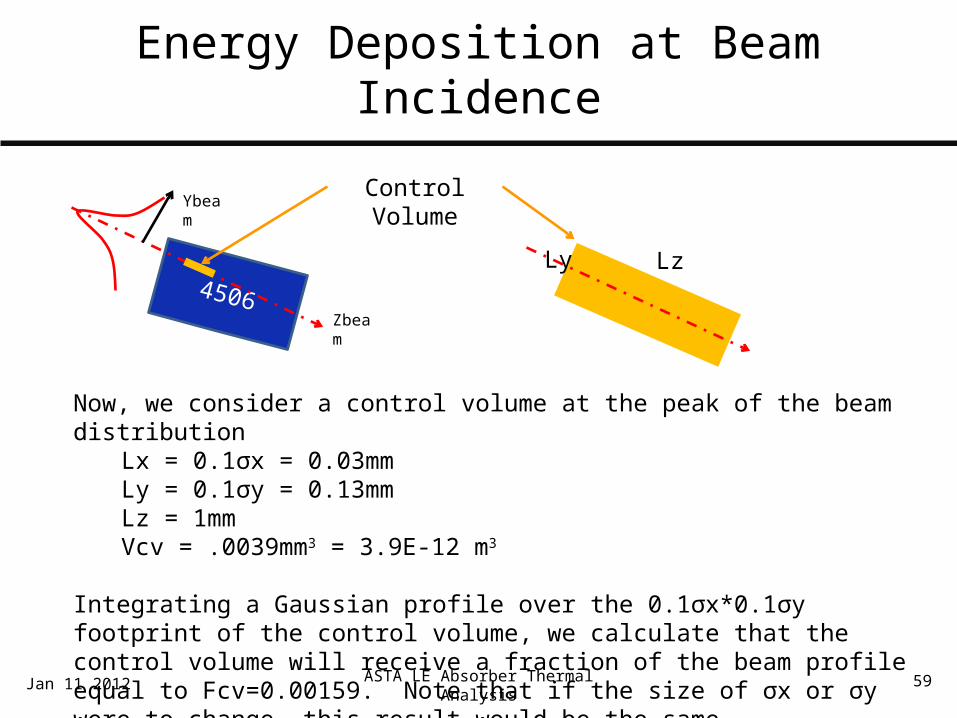
Now, we consider a control volume at the peak of the beam distributionLx = 0.1σx = 0.03mmLy = 0.1σy = 0.13mmLz = 1mmVcv = .0039mm3 = 3.9E-12 m3
Integrating a Gaussian profile over the 0.1σx*0.1σy footprint of the control volume, we calculate that the control volume will receive a fraction of the beam profile equal to Fcv=0.00159. Note that if the size of σx or σy were to change, this result would be the same.
Ly Lz
Control Volume
Energy Deposition at Beam Incidence
Jan 11 2012 ASTA LE Absorber Thermal Analysis

60
4506
Ybeam
Zbeam
Now, we can calculate energy deposition within the control volume
EDcv = EDp * Fcv * Lz = 3.09 J/mm/pulse * 0.00159 * 1mm = 0.00491 J/pulse in the control volume
Now, given the density and specific heat of graphite, we can calculate ΔT p = 1720 kg/m3 c = 550 J/kg*K
ΔT = EDcv / (Vcv * p * c)
Ly Lz
Control Volume
Energy Deposition at Beam Incidence
61
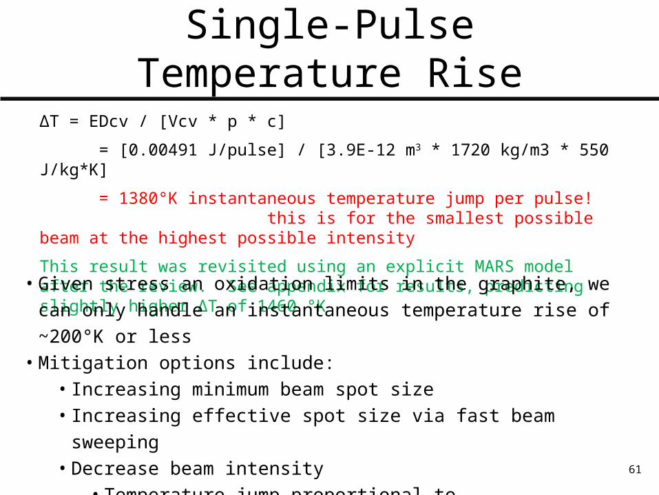
ΔT = EDcv / [Vcv * p * c]
= [0.00491 J/pulse] / [3.9E-12 m3 * 1720 kg/m3 * 550 J/kg*K]
= 1380°K instantaneous temperature jump per pulse! this is for the smallest possible beam at the highest possible intensity
This result was revisited using an explicit MARS model after the review. See appendix for results, predicting slightly higher ΔT of 1460 °K
• Given stress an oxidation limits in the graphite, we can only handle an instantaneous temperature rise of ~200°K or less
• Mitigation options include:• Increasing minimum beam spot size• Increasing effective spot size via fast beam sweeping• Decrease beam intensity
• Temperature jump proportional to particles/pulse• Acceptable temperatures if we limited absorbers to 1.25E13 e-/pulse
Single-Pulse Temperature Rise
ASTA LE Absorber Thermal Analysis 62
Pulse Transient
Jan 11 2012
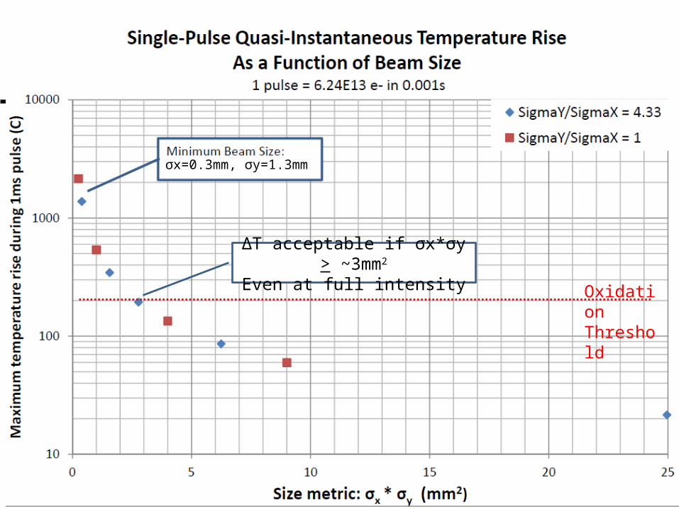
σx=0.3mm, σy=1.3mm
Oxidation Threshold
ΔT acceptable if σx*σy > ~3mm2
Even at full intensity
ASTA LE Absorber Thermal Analysis 63
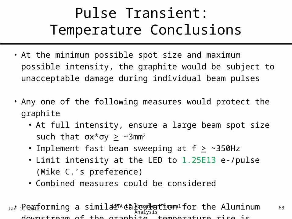
Pulse Transient: Temperature Conclusions
• At the minimum possible spot size and maximum possible intensity, the graphite would be subject to unacceptable damage during individual beam pulses
• Any one of the following measures would protect the graphite• At full intensity, ensure a large beam spot size such that σx*σy > ~3mm2
• Implement fast beam sweeping at f > ~350Hz• Limit intensity at the LED to 1.25E13 e-/pulse (Mike C.’s preference)• Combined measures could be considered
• Performing a similar calculation for the Aluminum downstream of the graphite, temperature rise is negligible. The Aluminum portions of the absorber do not impose any constraints.
Jan 11 2012

ASTA LE Absorber Thermal Analysis 64
Pulse Transient: Induced Stresses
• Now, we assess the stress state in the graphite as a result of the pulse transient thermal condition
• Assume mitigation scenario where temperature/oxidation constraint limits
maximum beam size to σx*σy > ~3mm2
• To see whether stress constraints are more stringent than the oxidization
constraint, we assess the stress condition under the following conditionso Full intensity: 6.24E13 e-/per pulseo σx*σy = 3mm2, σx = σy = 1.7mmo Single pulse instantaneous rise calculated near the beam incidence
location, beam divergence assumed to be smallo Temperature field in graphite imported for structural analysis
Jan 11 2012
ASTA LE Absorber Thermal Analysis 65
Pulse Transient: Induced Stresses
• Graphite IG-110 mechanical strength (per vendor datasheets)o Max flexural strength: 39MPa (5.5 ksi)o Max compressive strength: 78MPa (11 ksi)
• Calculate graphite stresses as follows:o Compare maximum principal stress to flexural strengtho Compare minimum principal stress to compressive strength
Jan 11 2012
ASTA LE Absorber Thermal Analysis 66
Pulse Transient: Temperature Field
Jan 11 2012
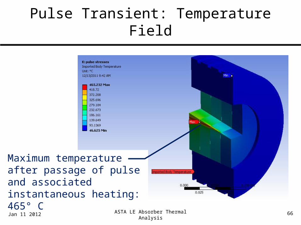
Maximum temperature after passage of pulse and associated instantaneous heating:465° C
ASTA LE Absorber Thermal Analysis 67
Pulse Transient: Induced Stresses
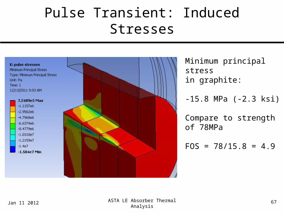
Minimum principal stress in graphite: -15.8 MPa (-2.3 ksi)
Compare to strength of 78MPa
FOS = 78/15.8 = 4.9
Jan 11 2012
ASTA LE Absorber Thermal Analysis 68
Pulse Transient: Induced Stresses
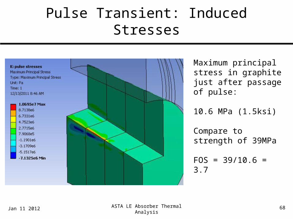
Maximum principal stress in graphite just after passage of pulse:
10.6 MPa (1.5ksi)
Compare to strength of 39MPa
FOS = 39/10.6 = 3.7
Jan 11 2012
ASTA LE Absorber Thermal Analysis 69
Pulse Transient: Stress Conclusions
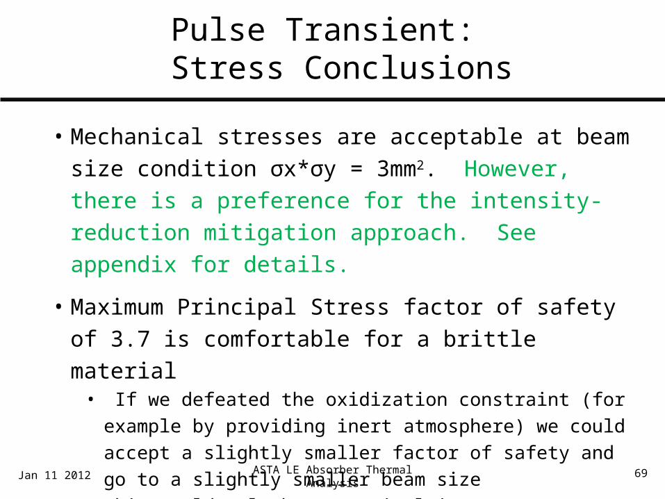
• Mechanical stresses are acceptable at beam size condition σx*σy = 3mm2. However, there is a preference for the intensity-reduction mitigation approach. See appendix for details.
• Maximum Principal Stress factor of safety of 3.7 is comfortable for a brittle material
• If we defeated the oxidization constraint (for example by providing inert atmosphere) we could accept a slightly smaller factor of safety and go to a slightly smaller beam size
• This would only be a marginal improvement – stress constraints would not permit the σx = 0.3mm/σy = 1.3mm beam size at full intensity
Jan 11 2012

ASTA LE Absorber Thermal Analysis 70
ASTA Low Energy Beam Absorber AnalysisOutline
•System Overview and Configuration• MARS Analysis Inputs• Material and Fluid Analysis Inputs• Thermal Model• Steady State Analysis and Beginning of Life Performance• Radiation Damage and End of Life Performance• Pulse Transient• System Transient Analyses• Conclusions
Jan 11 2012

ASTA LE Absorber Thermal Analysis 71
System Transient Analyses
• Three system transient analyses were run• Pulse decay case was run to characterize how long single-
pulse temperature jumps persist and to look at pulse-superposition effects
• The cold start beam-on transient case was run to characterize the warm-up time of the system
• As a possible accident scenario, case of cooling water failure was considered.
Jan 11 2012

ASTA LE Absorber Thermal Analysis 72
Pulse Decay Case
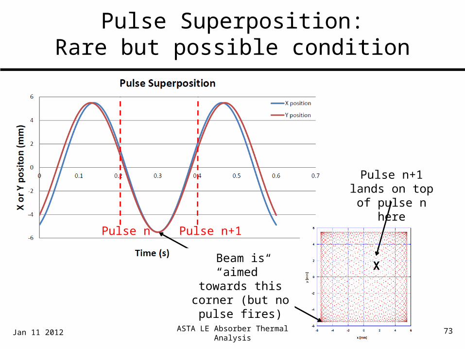
• Recall that beam sweeps sinusoidally in X and Y, at slightly different frequencies
• Assume that time-phasing between X and Y sweeping functions will be random
• A case exists where two subsequent pulses land in the same location of the absorber• This occurs when the both X and Y sweeping functions
“aim” the beam at a corner of the sweeping pattern midway between two pulses
Jan 11 2012
ASTA LE Absorber Thermal Analysis 73
Pulse Superposition:Rare but possible condition
Jan 11 2012
Pulse n Pulse n+1
X
Pulse n+1 lands on top of pulse n here
Beam is “aimed” towards this corner (but no pulse fires)

ASTA LE Absorber Thermal Analysis 75

ASTA LE Absorber Thermal Analysis 77
Pulse Decay Case
• Given that superposition will occur, how far have pulse-induced temperatures decayed after the 0.2s inter-pulse period?
• Assumptions• Same input pulse as stress analysis:
o Full intensity: 6.24E13 e-/per pulseo σx*σy = 3mm2, σx = σy = 1.7mmo Single pulse instantaneous rise calculated near the beam
incidence location, beam divergence assumed to be smallo Incident beam centered on absorber. This is slightly conservative,
because pulse superposition can only occur 2-3mm off-center
Jan 11 2012

ASTA LE Absorber Thermal Analysis 78
Pulse Decay
Jan 11 2012
Pulse n
Pulse n+1
Temperature jump caused by pulse n+1 will
occur here. Hand-calculated dT = 176° C(per method shown starting on slide 55)
Max temperature in graphite will jump to
494°C. Approaching, but below, self-imposed
oxidization limit
ASTA LE Absorber Thermal Analysis 79
Pulse Decay Case: Conclusions
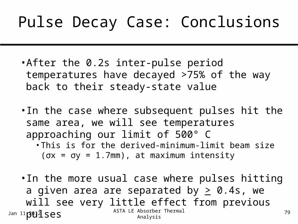
• After the 0.2s inter-pulse period temperatures have decayed >75% of the way back to their steady-state value
• In the case where subsequent pulses hit the same area, we will see temperatures approaching our limit of 500° C• This is for the derived-minimum-limit beam size (σx = σy = 1.7mm), at
maximum intensity
• In the more usual case where pulses hitting a given area are separated by > 0.4s, we will see very little effect from previous pulses
Jan 11 2012
ASTA LE Absorber Thermal Analysis 80
Warm Up Transient
•When we introduce beam to a cold absorber, how long will it take for mature temperature profiles to develop?
• Assumptions• 2.5kW temporally-averaged energy deposition• Same model and parameters as presented in steady-state
analysis section• Absorber starts at assumed cooling water temperature of
40°C
• Conclusion: temperature profile is fully developed after ~10 minutes
Jan 11 2012

ASTA LE Absorber Thermal Analysis 81
Runaway Transient @BOL
t = 1000s
Jan 11 2012

ASTA LE Absorber Thermal Analysis 82
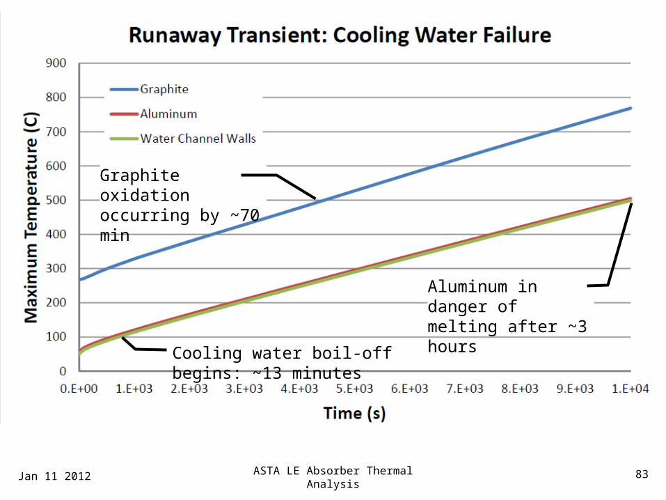
Runaway Transient
• As a possible accident scenario, case of cooling water failure was considered.
• How long do we have before something fails?
• Assumptionso Neglect natural convection and conduction to steelo Neglect phase change (boil-off) in cooling watero Assume continued application of 2.5kW beam powero Beginning-of-life graphite material properties
Jan 11 2012
ASTA LE Absorber Thermal Analysis 83
t = 0sSteady state condition
Jan 11 2012
Cooling water boil-off begins: ~13 minutes
Graphite oxidation occurring by ~70 min
Aluminum in danger of melting after ~3 hours

ASTA LE Absorber Thermal Analysis 84
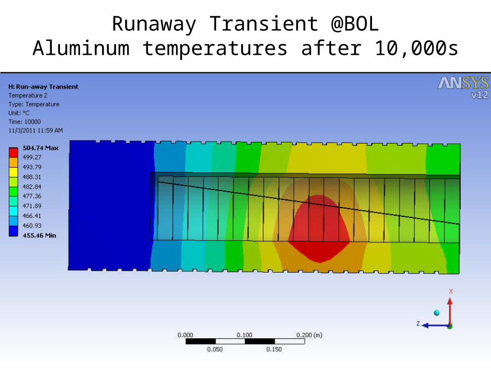
Runaway Transient @BOLSystem temperatures after 10,000s
t = 200s
Jan 11 2012
ASTA LE Absorber Thermal Analysis 85
Runaway Transient @BOLAluminum temperatures after 10,000s
Jan 11 2012

ASTA LE Absorber Thermal Analysis 86
Runaway Transient: Conclusions
• For the runaway transient, the considerable thermal capacitance of Aluminum shell allows us to survive an accident for a reasonable period of time• Permanent damage to LED would occur after ~1 hour• Catastrophic failure would occur after ~3 hours
• This should be plenty of time to detect the fault and turn the system off
Jan 11 2012

ASTA LE Absorber Thermal Analysis 87
ASTA Low Energy Beam Absorber AnalysisOutline
•System Overview and Configuration• MARS Analysis Inputs• Material and Fluid Analysis Inputs• Thermal Model• Steady State Analysis and Beginning of Life Performance• Radiation Damage and End of Life Performance• Pulse Transient• System Transient Analyses• Conclusions
Jan 11 2012
ASTA LE Absorber Thermal Analysis 88
ASTA Low Energy Beam Absorber Thermal Analysis: Conclusions
Jan 11 2012
• There are a few open issues that will need to be resolved by further testing and/or system wide decisions:
• Graphite/Aluminum thermal contact must achieve minimum value of ~250 W/m2K. Existing data and worst-case calculations indicate that this should not be a problem. However, we should get confirmation from planned window testing.

ASTA LE Absorber Thermal Analysis 89
ASTA Low Energy Beam Absorber Thermal Analysis: Conclusions
Jan 11 2012
• In order to prevent graphite damage due to individual pulses, we must either:
• At full intensity, ensure a large beam spot size such that σx*σy > ~3mm2
• Implement fast beam sweeping at f > ~350Hz• Limit intensity at the LED to 1.25E13 e-/pulse. (Preferred
approach, see appendix for additional analysis)• Consider some combined measure
• Given that these open issues are tractable, the thermal design of the LED is acceptable

ASTA LE Absorber Thermal Analysis 90
Questions and Discussion
• Included in the scope of this review• Configuration of the ASTA Low Energy Dumps• Thermal analysis methodology and results
• Excluded from the scope of this review• Radiation analysis and shielding assessment
• Review Charge: please review the configuration and thermal analysis of the low energy dumps and assess whether
• Absorber configuration is appropriate• Analysis assumptions, method, and results are reasonable• System is ready to move on to detailed mechanical design
Jan 11 2012
ASTA LE Absorber Thermal Analysis 91
ASTA Low Energy Beam Absorber AnalysisOutline
•System Overview and Configuration• MARS Analysis Inputs• Material and Fluid Analysis Inputs• Thermal Model• Steady State Analysis and Beginning of Life Performance• Radiation Damage and End of Life Performance• Pulse Transient• System Transient Analyses• Conclusions• Appendix 1 – Reduced Intensity Cases.• Appendix 2 – 55MeV Analysis
Updated: Feb 07 2012

ASTA LE Absorber Thermal Analysis 92
Appendix 1 – Reduced Intensity Cases
• The analyses described above…• Identified a stress and temperature issue caused by
individual beam pulses at the maximum possible intensity (6.24E13 e-/pulse) and the minimum possible beam size (σx= 0.3mm, σy=1.3mm)
• Presented three possible mitigations:• At full intensity, ensure a large spot size such that σx*σy > ~3mm2• Implement fast beam sweeping at f > ~350Hz• Limit intensity at the LED to 1.25E13 e-/pulse
• Focused on the beam spot size mitigation option
Updated: Feb 07 2012

ASTA LE Absorber Thermal Analysis 93
Appendix – Reduced Intensity Cases
• In reviewing this analysis package, Mike C. determined that the intensity limitation mitigation would be the most practical to implement
• In a design review held on 11-Jan-2012, the review panel requested explicit analysis associated with the reduced intensity cases
• Specific review recommendations w.r.t. beam intensity• Rather than using a scaling approach, build an explicit
MARS model to quantify peak single-pulse heating effects• Revisit stress and temperature analyses for low-intensity
scenariosUpdated: Feb 07 2012

ASTA LE Absorber Thermal Analysis 94
Review Recommendations:MARS model for single-pulse effects
• In the presented analysis, a scaling approach was used to calculate the Gaussian peak of the local, instantaneous energy deposition associated with single pulses. (See slides 50-61)
• The review panel recommended building an explicit, fine MARS model to better capture beam incidence effects and confirm the scaling approach
• Igor Rakhno built such a model• MARS element sizes are very fine as compared to beam size:
0.1σx X 0.1σx X 1mm• Peak energy deposition compares well (~10%) with that obtained by
scaling approach• This explicitly modeled value is considered to be more accurate, and is
used for subsequent single-pulse calculations in this appendix.
Updated: Feb 07 2012

ASTA LE Absorber Thermal Analysis 95Updated: Feb 07 2012
7.5°
• Localized High-resolution MARS model built for beam incidence area
• Maximum energy deposition (very near beam incidence) = .0802 GeV/(g*e-)
• This compares well with calculation done by large-cell scaling. This estimate is ~9% higher.
Review Recommendations:MARS model for single-pulse effects
ASTA LE Absorber Thermal Analysis 96Updated: Feb 07 2012
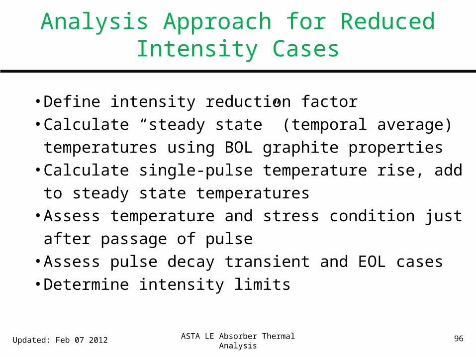
• Define intensity reduction factor• Calculate “steady state” (temporal average) temperatures using
BOL graphite properties• Calculate single-pulse temperature rise, add to steady state
temperatures• Assess temperature and stress condition just after passage of
pulse• Assess pulse decay transient and EOL cases• Determine intensity limits
Analysis Approach for Reduced Intensity Cases

ASTA LE Absorber Thermal Analysis 97
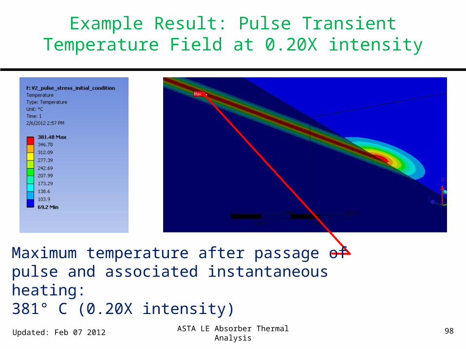
Example Result: Pulse Transient Temperature Field at 0.20X intensity
Maximum temperature after passage of pulse and associated instantaneous heating:381° C (0.20X intensity)
This represents the temp. field of a single pulse added to a steady-state temp. profile. (Structure of steady state profile is not visible due to color map scaling)
See detail next slide
ASTA LE Absorber Thermal Analysis 98
Example Result: Pulse Transient Temperature Field at 0.20X intensity
Updated: Feb 07 2012
Maximum temperature after passage of pulse and associated instantaneous heating:381° C (0.20X intensity)
ASTA LE Absorber Thermal Analysis 99
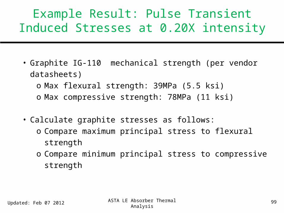
Example Result: Pulse Transient Induced Stresses at 0.20X intensity
• Graphite IG-110 mechanical strength (per vendor datasheets)o Max flexural strength: 39MPa (5.5 ksi)o Max compressive strength: 78MPa (11 ksi)
• Calculate graphite stresses as follows:o Compare maximum principal stress to flexural strengtho Compare minimum principal stress to compressive strength
Updated: Feb 07 2012

100Updated: Feb 07 2012
Example Result: Pulse Transient Von Mises Stresses at 0.20X intensity
Von Mises Stress field just after passage of pulse:
Not a valid failure criterion for a brittle material, but informative about the interplay/imbalance between stress components
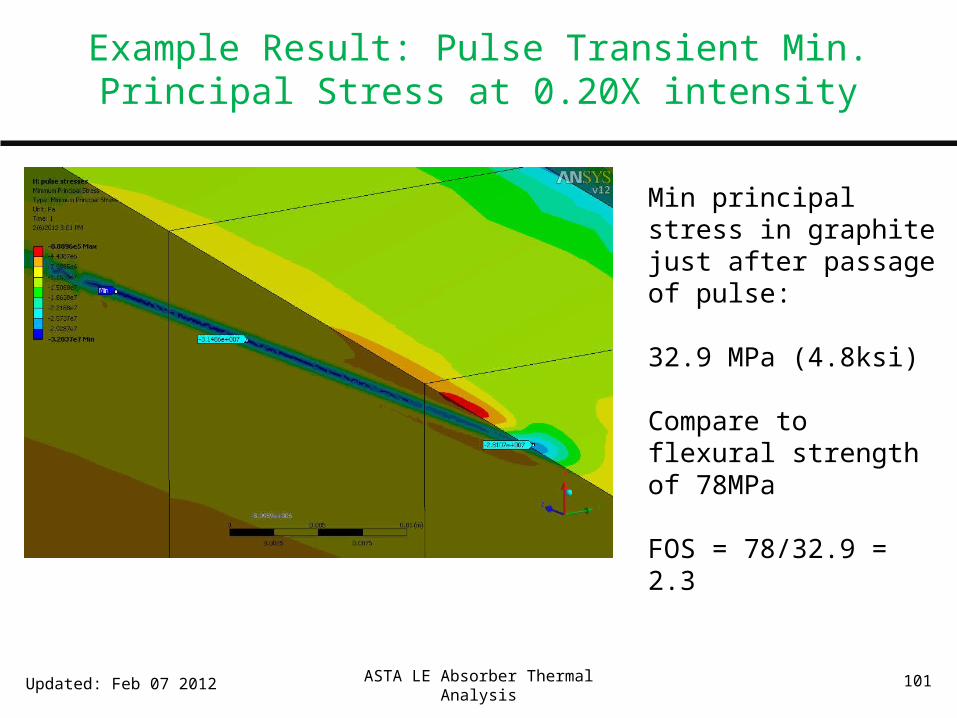
ASTA LE Absorber Thermal Analysis 101
Min principal stress in graphite just after passage of pulse:
32.9 MPa (4.8ksi)
Compare to flexural strength of 78MPa
FOS = 78/32.9 = 2.3
Updated: Feb 07 2012
Example Result: Pulse Transient Min. Principal Stress at 0.20X intensity

ASTA LE Absorber Thermal Analysis 102
Maximum principal stress in graphite just after passage of pulse:
1.6 MPa (0.2ksi)
Compare to flexural strength of 39MPa
FOS = 39/1.6 = 24
FOS on this tensile-type stress is high, in part because part is biased in compression by shrink fit
Updated: Feb 07 2012
Example Result: Pulse Transient Max. Principal Stress at 0.20X intensity

ASTA LE Absorber Thermal Analysis 103Updated: Feb 07 2012
Pulse n
Pulse n+1
Temperature jump caused by pulse n+1 will
occur here.
Temperatures have already decayed to
within ~7°C of steady-state value
Example Result: Pulse Transient Temperature decay at 0.20X intensity

ASTA LE Absorber Thermal Analysis 104
Reduced Intensity Pulse Decay Cases: Conclusions
• After the 0.2s inter-pulse period temperatures have decayed nearly all the way back to their steady-state value
• Due to the smaller size of the affected volume and the lower energy deposited, the decay is much quicker in the reduced intensity cases.
• Occasional pulse superposition is not a concern at reduced intensity
Updated: Feb 07 2012

105Updated: Feb 07 2012
Example Result: BOL vs EOL Steady State Temps at 0.20X intensity
Beginning of Life (BOL)Max. Temperature = 86°C*
* These are temporal-average temperatures; instantaneous single pulse effects add linearly to these
End of Life (EOL) Shown on same color scaleAfter 1.4E21 electrons total~ 20 calendar yearsSee slide 47 for damage mapMax. Temperature = 129°C*
ASTA LE Absorber Thermal Analysis 106
BOL vs EOL Analyses at Reduced Intensity
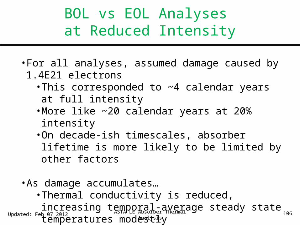
• For all analyses, assumed damage caused by 1.4E21 electrons• This corresponded to ~4 calendar years at full intensity•More like ~20 calendar years at 20% intensity• On decade-ish timescales, absorber lifetime is more likely to
be limited by other factors
• As damage accumulates…• Thermal conductivity is reduced, increasing temporal-
average steady state temperatures modestly• Heat capacity and density are unchanged (to first order), so
magnitude of per-pulse temperature jumps is not affected (see slides 60-61 for relevant equation)
Updated: Feb 07 2012
ASTA LE Absorber Thermal Analysis 107
BOL vs EOL Analyses at Reduced Intensity
• In contrast to the full intensity/large spot size cases, in reduced intensity/small spot size cases, temperatures are driven much more by pulse effects that steady state temperatures
• For reduced intensity cases, though steady state temperatures increase modestly at EOL, this is a small contributor to overall stress and temperature limits
• Additionally, it would take much longer to achieve the assumed EOL damage condition at reduced intensity, making other failure modes more likely
• Graphite damage and EOL performance is much less of a driver at reduced intensity
Updated: Feb 07 2012

ASTA LE Absorber Thermal Analysis 108
Reduced Intensity Results
• Preceding slides described the analysis method at one intensity condition (20% intensity)
• Similar analyses were performed at a few intensity conditions to establish an intensity limitation for this design
• Results tabulated on next slide
Updated: Feb 07 2012

109
Absorber Performance vs. Intensity Reduction for smallest expected beam size: σx=0.3mm σy=1.3mm
Intensity Factor
e- per pulse
Max. Temp (C)
[1]
Min. Factor of Safety
[3]
Comments
1.00 6.24E13 1745°C Not evaluated
By inspection, stresses unacceptable
0.50 3.12E13 890°C 0.9 [4] Stresses unacceptable, even if temperature constraints were defeated by inert atmosphere
0.25 1.56E13 466°C [2] 1.9 Stresses and temperatures simultaneously becoming marginal
0.20 1.25E13 381°C [2] 2.3 Stresses and temperatures are reasonable
[1] Maximum instantaneous temperature at BOL just after pulse passage. In the absence of inert atmosphere, compare to material oxidation threshold of 500 °C
[2] Add ~45C at EOL[3] Driving case was min. principal (compressive) stresses just after passage of a pulse, in all cases[4] Material failure expected for FOS<1

ASTA LE Absorber Thermal Analysis 110
Reduced Intensity: Observations
• For the smallest expected beam size, we can operate reasonably at 20% intensity, 1.25E13 e-/pulse• This limit is higher than the previously estimate of 9E12 e- per pulse,
which was based on a less rigorous calculation
• Absorber will be approaching oxidation and stress limits at 25% intensity. We could consider operating here, but there would be some risk to the absorber. The absorber is replaceable, so that risk might be acceptable.
• Stress limits are encountered at approximately the same intensity condition as oxidization limits. If we were to remove the oxidization concern by adding inert atmosphere, it wouldn’t buy us very much.
Updated: Feb 07 2012
ASTA LE Absorber Thermal Analysis 111
Reduced Intensity: Conclusions
• Recommend implementing an intensity limit of 20%, 1.25E13 e-/pulse
Updated: Feb 07 2012

ASTA LE Absorber Thermal Analysis 112
ASTA Low Energy Beam Absorber AnalysisOutline
•System Overview and Configuration• MARS Analysis Inputs• Material and Fluid Analysis Inputs• Thermal Model• Steady State Analysis and Beginning of Life Performance• Radiation Damage and End of Life Performance• Pulse Transient• System Transient Analyses• Conclusions• Appendix 1 – Reduced Intensity Cases.• Appendix 2 – 55MeV Analysis
Updated: June 08 2012

ASTA LE Absorber Thermal Analysis 113
Appendix 2 – 55MeV Analysis
• Component measurements suggest that we may be able to achieve higher-than-expected beam energy out of the injector
• Mike Church requested re-analysis at a beam energy of 55MeV• Assumed “20% Intensity” Scenario for all re-analysis
(1.25E13 e-/pulse, 10μA average beam current)
• Analyses performed• Single-pulse energy deposition• Steady state thermal condition at Beginning of Life
• Conclusion: Increase to 55MeV beam energy has very little thermal effect on the system
Updated: June 08 2012

ASTA LE Absorber Thermal Analysis 114
Single-Pulse energy deposition @55MeV
• A fine-meshed MARS model is used to assess peak values of energy deposition near the surface
• Analysis method is described starting on p.94 of this package• Results at 55MeV are identical to results at 50MeV to within
the precision of the calculation
Updated: June 08 2012
Metric Result @50MeV Result @55MeV
Peak Energy Deposition (at surface) .0802 GeV/(g*e-) .0800 GeV/(g*e-)
Maximum pulse-induced instantaneous temperature rise, for 20% intensity scenario
ΔT = 300°C ΔT = 299°C
ASTA LE Absorber Thermal Analysis 115
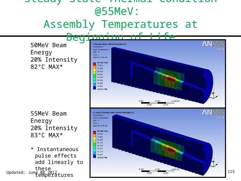
Steady-State Thermal Condition @55MeV: Assembly Temperatures at Beginning of Life
Updated: June 08 2012
50MeV Beam Energy20% Intensity82°C MAX*
55MeV Beam Energy20% Intensity83°C MAX*
* Instantaneous pulse effects add linearly to these temperatures
ASTA LE Absorber Thermal Analysis 116
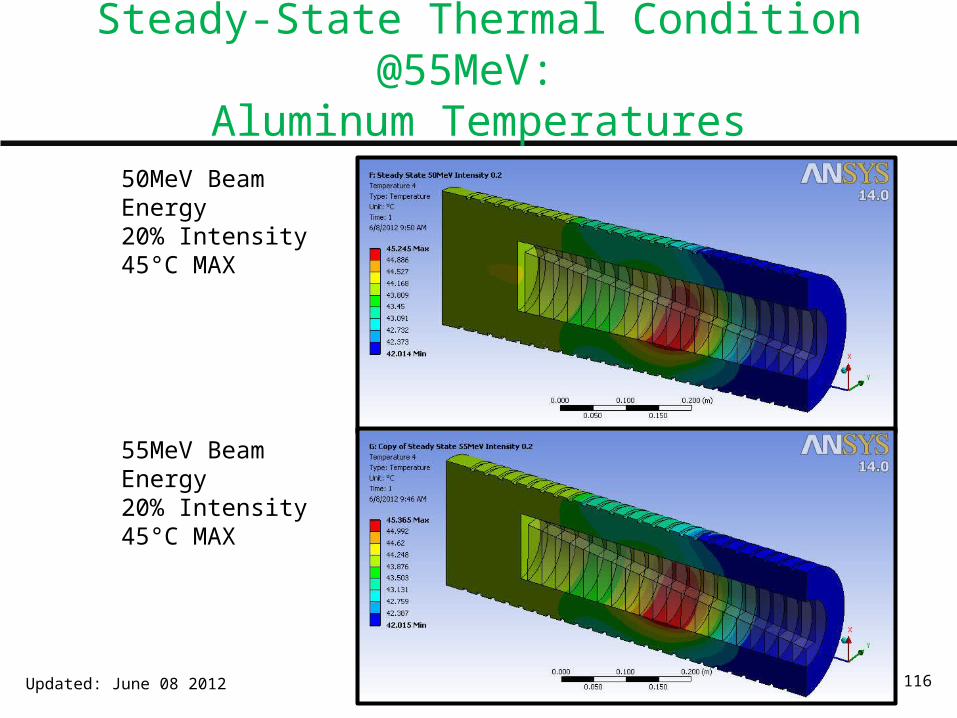
Steady-State Thermal Condition @55MeV: Aluminum Temperatures
Updated: June 08 2012
50MeV Beam Energy20% Intensity45°C MAX
55MeV Beam Energy20% Intensity45°C MAX

ASTA LE Absorber Thermal Analysis 117
Steady-State Thermal Condition @55MeV
Updated: June 08 2012
Metric Result @50MeV Result @55MeV
Total Average Beam Power(20% intensity, 10μa beam current)
500W 550W
Beam power dissipated in graphite/aluminum absorber core and rejected to cooling water
449W 490W
Maximum “steady state” graphite temperature
82°C 83°C
Peak graphite temperature just after passage of a beam pulse
382°C 382°C
Maximum “steady state” aluminum temperature
45°C 45°C

ASTA LE Absorber Thermal Analysis 118
Conclusions – 55MeV Analysis
• Thermal performance of the absorber is nearly identical at 50MeV and 55MeV
• Based on the similarity of temperature conditions, stress analysis was not repeated for 55MeV cases
• From a thermal perspective, there is no issue running at 55MeV and 20% intensity
Updated: June 08 2012