Embed Size (px)
Citation preview

60
Assessment of the Finite Element Analysis of Portal Steel Frames
with Cold Formed Rectangular Hollow Sections Including
Imperfections and Residual Stresses
Tarek Sharaf1, Sarah Elglaad2, Mohamed ElGhandour3, Ashraf ElSabbagh4
ABSTRACT
This paper aims to assess the finite element analysis in predicting the behavior of portal steel frames fabricated from cold
formed steel (CFS) rectangular hollow sections. ABAQUS ® was used in the current research to discuss and validate the
finite element models with experimental tests on portal frames and knee joints of portal frames. The influence of the nonlinear
finite element solution methods, loading type controls, initial imperfections in CFS, residual stresses, mesh density, and
different element types were studied. Also, the method of representing the initial imperfection were considered and found to
have significant influence on the results. These considerations enabled performing an extensive parametric study. The
parametric study consisted of 144 portal frames with various dimensions and RHS sizes. The ultimate load capacity as well
as horizontal and vertical displacements that represent the nonlinear behavior of such steel frames were obtained. The failure
modes due to material yielding, local buckling, plastic hinges formation as well as interaction of material yielding, and local
buckling were also recorded.
Keywords: Cold formed hollow sections, Steel frames, Knee joints, Finite element analysis, Initial imperfections, Residual
stresses, Failure Modes.
1. INTRODUCTION
Cold formed sections have already been used in steel
structures providing various benefits to a range of
construction and mechanical applications which include
portal frames in a large scale that are consisted of open and
closed sections. For most common cold formed opened
sections, channels attached back-to-back and Z-section
members were chosen to design the steel frames by many
researchers. Cold-formed tubes are available in many forms
such as: rectangular hollow sections (RHS), square hollow
sections (SHS), circular hollow sections (CHS), and oval
hollow section (OHS). Androić et al. [1] performed a
comparison between cold formed and hot finished hollow
sections and it was shown from the comparison that the
manufactured cold-formed hollow sections according to EN
10219 [39] are appropriate for all types of steel structures.
Several researches studied the new sections used in steel
structure construction applications such as oval hollow
sections. Zhu and Young [36] tested 28 columns that were
fabricated from cold formed steel oval hollow sections
(OHS) subjected to axial compression between fixed ends.
The study evaluated the failure modes such as flexural
buckling, local buckling, and material yielding. Lie et al. [2]
studied the behavior of cold formed rectangular steel thick-
walled columns under either axial or eccentric compression
using both experimental tests and FEA including the effects
of residual stresses and initial imperfection. The results show
that direct loaded cold-formed rectangular steel columns
have higher cold-formed effects than indirect cold-formed
rectangular steel columns and the higher bearing capacity for
cold formed rectangular steel columns was under axial loads.
Different failure modes (overall buckling or local buckling)
occur for cold formed hollow sections due to different
slenderness ratios and width-to-thickness ratios [3] and local
buckling mainly occurred at the welded parts that leads to
failure in welding [4-5]. Wilkinson [6] used the finite
element analysis to investigate trends and the occurrence of
inelastic instability in cold formed RHS beams. The study
illustrated that there are three main types of residual stresses
for RHS; membrane residual stresses, bending residual
stresses, and layering residual stresses, however bending
PORT SAID ENGINEERING JOURNAL
Faculty of Engineering - Port Said University
Volume 25 No. 2 September 2021 pp. 60 - 79
-Civil Engineering-
_____________________________________________________________________
1 Associate Professor Civil Engineering Department, Faculty of
Engineering, Port Said University, Port Said, Egypt, email:
[email protected] 2 Researcher, Civil Engineering Department, Faculty of Engineering,
Port Said University, Port Said, Egypt email: [email protected].
3 Professor Civil Engineering Department, Faculty of Engineering,
Port Said University, Port Said, Egypt, email
4 Associate Professor Civil Engineering Department, Faculty of
Engineering, Port Said University, Port Said, Egypt,
email:[email protected]
Received: 05-05-2021, Accepted: 12-07-2021
DOI: 10.21608/PSERJ.2021.75314.1111

61
residual stresses and layering residual stresses were used in
FEA models in based on Key [37]. Wilkinson and Hancock
[7] provided tests on various types of knee joints for steel
portal frames constructed from cold-formed rectangular
hollow sections (RHS) to study the behavior of the
connections to form plastic hinges. Using the ANSYS
nonlinear finite element analysis programme, EL-Ghandour
explored alternative approaches for stiffening various types
of knee joints for steel portal frames produced from cold-
formed rectangular hollow sections (RHS) to investigate the
ability of the connections to form plastic hinges [40].
Following the approach in [41], V.Priyadarshini1 et al
studied experimentally the behavior of cold formed steel
frames using hollow section which connected along major
and minor axes connections. It resulted in the load carrying
capacity of frames connected along the major axis is found
to be 38 percent higher than that of frames connected along
the minor axis. Also the deflection of the minor axis
connected frame was found to be 6.06 percent higher than
that of the main axis connected frame, so major axis
connected frames work better than minor axis connected
frames. Wilkinson and Hancock [8] studied three large scale
portal frames manufactured from cold-formed RHS in both
Grade C350 and Grade C450 steel. The results showed that
each frame formed a plastic collapse mechanism. Mang et al.
[9] studied the static behavior of knee joints made from
circular hollow sections (CHS). Puthli et al. [10] studied the
fatigue behavior of knee connections in both RHS and CHS.
Kwon et al. [11] provided portal frames which consisted of
closed cold-formed steel PRY sections to investigate the
compressive and the flexural strengths of the PRY sections,
the structural behavior of the connections including the
moment-rotation relation, and the yield and the ultimate
moment capacities of the connections. The connection test
results were compared with those achieved by using
advanced analysis procedures. Other researchers [12-15]
performed studies on the effective moment framing in cold-
formed steel structures to employ cold-formed steel C
sections with bolted moment connections as primary
structural members in low to medium rise buildings as well
as in portal frames with medium spans. Chung et al. [16] and
Darcy and Mahendran [17] studied bolted moment
connections in portal frames. While other researchers [18-
22] presented the study of stiffened and unstiffened knee
connections for portal frames with CHS and RHS members.
Mahendran and Avery [23] and Avery [24] used the
experimental and the FEA to analyze steel frame structures
comprising compact and non-compact sections, residual
stresses and local buckling were studied as well. Other
studies [25-27] proposed the viability to construct portal
frames fabricated from cold formed sections with spans up
to 12 m which interested with eaves and apex joints to be
rigid. Kurobane [28] experimentally evaluated the behavior
of truss structures with tube-to-tube connections.
The current research aims to evaluate the use of the finite
element analysis to figure out the behavior of cold formed
steel structures as well as to determine which finite element
is more suitable to be used in the analysis. Also, the effect of
both residual stresses and initial imperfections modeled by
the structural mode shapes and which mode shape should be
used by the designer to analyze such structures.
2. FINITE ELEMENT MODELLING
Finite element models were created for comparison with
experimental tests results to investigate the behavior of steel
frame studied by Avery [24] and various types of knee joints
of portal frames fabricated from CFHS studied by Wilkinson
and Hancock [29]. This section aims to study a series of finite
element models with the effect of different inputs such as
initial imperfection and residual stresses as well as the effect
of mode shapes and then compare them with the
experimental results.
2.1. Frame Finite Element Model
The frame model consists of cold-formed rectangular
hollow sections (2001004 RHS). The frame span was 4.0
m between column center lines while the height was 3.0 m.
Minor axis bending was restrained to exclude out-of-plane
column buckling, Avery [24]. Both rectangular hollow
sections of the beam and the column were connected using
welding; connections were modelled with appropriate
contact in ABAQUS ®. The floor girder and the two-column
base plates, shown in Figure 1, were modeled as a long thick
plate with a thickness of 25 mm that was welded directly to
the ends of the two columns, as shown in Figure 2, to act as
a floor girder which rested on roller bearings boundary to be
free and move laterally in-plane as shown in Figure 1.
Figure 1:Test experiment and loading arrangement Avery
[24]

62
Figure 2: The three-dimensional finite element model of
frame with long thick base plate
2.1.1. Nonlinear Solution
The standard static general method (the Newton‐Raphson
method) was used to model the frame with maximum
number of load increments = 100, initial increment size =
0.05, maximum increment size = 0.05 and minimum
increment size = 0.000001 [24].
2.1.2. Material Modeling
Young’s modulus, Poisson’s ratio, and material
nonlinearity were taken into consideration in the finite
element analysis. It was essential to input the material
accurately in the finite element analysis as it significantly
affects the results, so it must follow the multi-linear stress-
strain curves obtained from tensile testing of the 2001004
RHS flange and web samples grade 350 steel that were
presented in Avery [24]. The average of each of the two
specimens of flange and web was taken for use in the finite
element analysis model. Equations (1) and (2) [38] were used
to convert stress-strain data conducted from tensile test to
true stress and logarithmic plastic strain. Furthermore, the
values resulting from the equations were entered into the FE
program. The relation between true stress and true plastic
strain is shown in Figure (3). Linear elastic material elasticity
modulus and Poisson’s ratio were E = 200000 MPa, 𝜐 = 0.3,
respectively .
𝜎𝑡𝑟𝑢𝑒 = 𝜎𝑛𝑜𝑚(1 + 𝜀𝑛𝑜𝑚) (1)
𝜀𝑝(ln) = ln(1 + 𝜀𝑛𝑜𝑚) −𝜎𝑡𝑟𝑢𝑒𝐸
(2)
Figure 3: True stress-strain curve derived from a tensile
coupon test for grade 350 steel [24]
2.1.3. Element Type and Mesh Density
Different shell elements are available in the finite element
software. All the quadrilateral shell elements (S4, S4R,
S4R5, and S8R5) are usually used to model thin structural
elements which suites the analysis of thin-walled structure.
It is necessary to obtain more accurate results and therefore,
comparisons must be made between different densities and
element types to estimate the sensitivity of the element. Four
shell elements and three mesh densities (coarse 21 21
mm2, medium 14 14 mm2, and fine 7 7 mm2), as shown
in Figure (4), were chosen in the current study to verify the
frame in Avery [24].
(a) coarse 21 x 21 mm2 (b) medium 14 x 14 mm2 (c) fine 7 x 7 mm2
Figure 4:Three different finite element meshes for frame
connection
Only the S4 element uses full integration while the rest of
the elements use the reduced integration. Finite element
types: S4, S4R and S4R5 use linear interpolation, but the
element S8R5 generates a quadratic shape function. For first-
order shell elements which generate linear interpolation, S4
and S4R have 4-node doubly curved general-purpose
thin/thick shell with six degrees of freedom at each node:
three translational and three rotational. However, S4R5 has
4-node doubly thin curved shell only with five degrees of
freedom at each node: three translational and two in-plane
rotational. The second-order shell elements such as S8R5 has
8-node doubly thin curved shell with five degrees of freedom
per node.
Long thick plate
t=25mm

63
2.1.4. Loads and Boundary Conditions
The frame model was loaded using load control method
which was applied as equal vertical loads at the center of the
top of each column and horizontal load as concentrated force
at a thick long plate adjacent to the base of the right-hand
column to simulate vertical and horizontal jacks in the test
[24]. Vertical loads were applied on the two reference points
located at the centroids of the top of two columns, which are
coupled with the surfaces of the cross-sections at both tops
of frame columns. The vertical to horizontal load ratio was
approximately 8:1 where the vertical load was approximately
eight times the horizontal load. Loads were implemented
simultaneously in the model. Translation DOF U1 was
restrained at the top of the left column at reference point
which was coupled with the associated nodes in the top of
the left column.
To ensure that the long thick base plate which was free to
move laterally in-plane was modelled to simulate the test, its
boundary conditions, as indicated in Figure 5, were:
translations U1 and U2 were free, U3 was restrained, and all
rotations UR1, UR2, and UR3 were restrained. The frame
test was full lateral restraint because the aim of the test is to
investigate the influence of in-plane buckling and prevent
lateral (out-of-plane) movement. Hence, the frame was
restrained laterally, i.e., the DOF U2 was retrained, at five
places to prevent the out-of-plane movement. Three was at
the middle point and near end points while the other two
were at the base plate near the two column bottoms, as shown
in Figure 5, to simulate the lateral supports shown in Figure
1.
Figure 5: Finite element meshing, loading and boundary
conditions for frame.
2.1.5. Initial Geometric Imperfections
It is known that initial geometric imperfections affect the
thin-walled cold-formed members remarkably. Initial
imperfection explicitly influences the frame strength where
the ultimate load decreases and the ductility increases. In the
present study, the magnitudes of the imperfections were
taken as a portion of the plate thickness (0.1t, 0.5t, and 1.0t)
[30, 34, 35].
Two steps have been implemented for the finite element
analysis:
Firstly, linear elastic buckling analysis was carried out to
obtain twelve mode shapes for the frame. Then, check all the
modes to determine which mode shape should be used to
generate the initial imperfections in the non-linear analysis. Secondly, the non-linear analysis including both material
nonlinearity and geometric nonlinearity, residual stresses
(RS), and initial imperfections (IMP) was performed. Results
were conducted for the finite element models with different
values of initial imperfections (W-IMP) and without initial
imperfections (Wo-IMP) to show the influence of
imperfection on the frame and compare results with the
experimental tests. 2.1.6. Residual Stresses
Longitudinal membrane, longitudinal bending,
longitudinal layering, transverse bending, and transverse
layering residual stress components were measured by Key
and Hancock [31]. They indicated that there are two types of
residual stresses which have the most important effect on
cold-formed steel structure members, as shown in Figure (6),
namely:
1- Longitudinal bending residual stresses.
2- Membrane residual stresses.
Residual stresses were simplified in Figure (6) based on
Key and Hancock [31].
Figure 6: Longitudinal membrane and bending residual stress
distributions for rectangular hollow sections (top) [31],
Definition of bending and membrane residual stress (bottom)
The residual stresses were modelled in the predefined field
outside and inside rectangular hollow sections as shown in
64
Figure 6. To model the distribution of bending residual stress
in cold-formed rectangular hollow sections, nine integration
points through the thickness of the shell element were used
instead of the default of five integration points [24].
2.1.7. Results and Discussion:
2.1.7.1. Mesh Sensitivity Results:
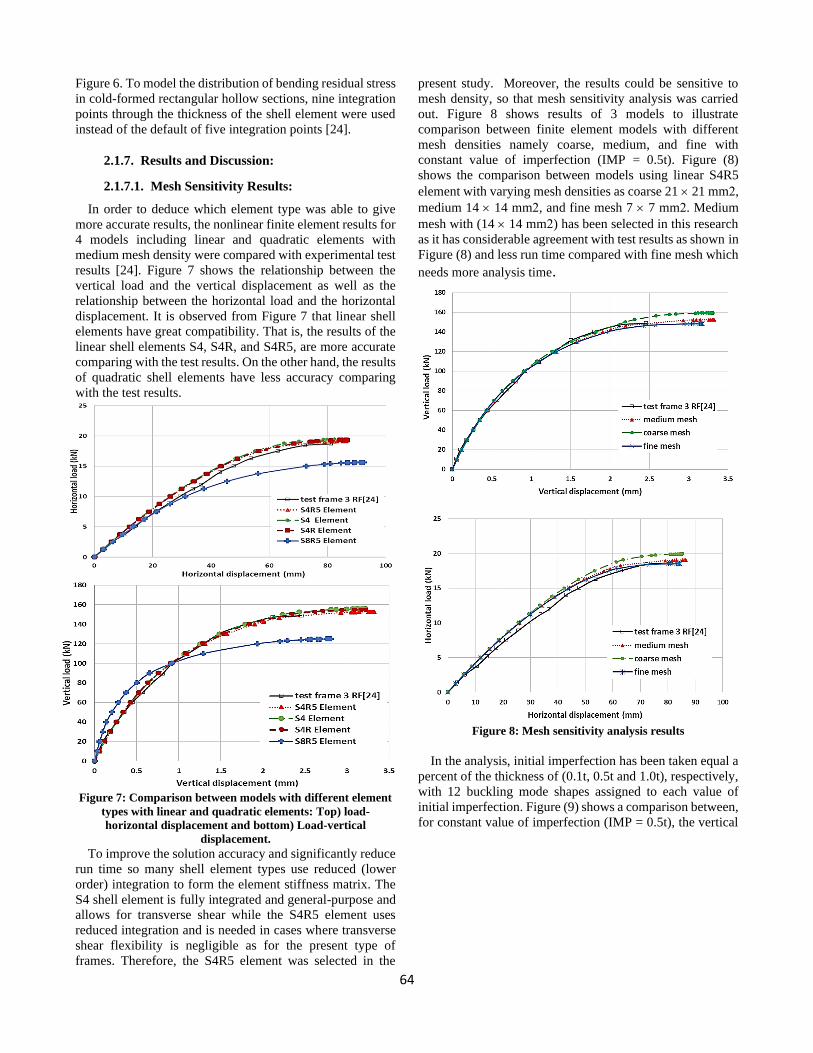
In order to deduce which element type was able to give
more accurate results, the nonlinear finite element results for
4 models including linear and quadratic elements with
medium mesh density were compared with experimental test
results [24]. Figure 7 shows the relationship between the
vertical load and the vertical displacement as well as the
relationship between the horizontal load and the horizontal
displacement. It is observed from Figure 7 that linear shell
elements have great compatibility. That is, the results of the
linear shell elements S4, S4R, and S4R5, are more accurate
comparing with the test results. On the other hand, the results
of quadratic shell elements have less accuracy comparing
with the test results.
Figure 7: Comparison between models with different element
types with linear and quadratic elements: Top) load-
horizontal displacement and bottom) Load-vertical
displacement.
To improve the solution accuracy and significantly reduce
run time so many shell element types use reduced (lower
order) integration to form the element stiffness matrix. The
S4 shell element is fully integrated and general-purpose and
allows for transverse shear while the S4R5 element uses
reduced integration and is needed in cases where transverse
shear flexibility is negligible as for the present type of
frames. Therefore, the S4R5 element was selected in the
present study. Moreover, the results could be sensitive to
mesh density, so that mesh sensitivity analysis was carried
out. Figure 8 shows results of 3 models to illustrate
comparison between finite element models with different
mesh densities namely coarse, medium, and fine with
constant value of imperfection (IMP = 0.5t). Figure (8)
shows the comparison between models using linear S4R5
element with varying mesh densities as coarse 21 21 mm2,
medium 14 14 mm2, and fine mesh 7 7 mm2. Medium
mesh with (14 14 mm2) has been selected in this research
as it has considerable agreement with test results as shown in
Figure (8) and less run time compared with fine mesh which
needs more analysis time.
Figure 8: Mesh sensitivity analysis results
In the analysis, initial imperfection has been taken equal a
percent of the thickness of (0.1t, 0.5t and 1.0t), respectively,
with 12 buckling mode shapes assigned to each value of
initial imperfection. Figure (9) shows a comparison between,
for constant value of imperfection (IMP = 0.5t), the vertical

65
and horizontal load with the vertical and horizontal
displacement, respectively.
Figure 9: Load-displacement relations with value of
imperfection (0.5t) and it was analyzed using 12 buckling
mode shapes.
It is realized that the second method of imperfection, 50
percent of the thickness, accompanied with the mode shape
number 2, provide the most critical imperfection, and give
the best results comparing with the test results The failed in-
plane instability, yielding material, and local buckling near
the base of both columns and top of each column as shown
in Figure (10).
Figure (11) shows the initial imperfections’ sensitivity for
the most suitable buckling mode (mode 2) using different
imperfection magnitudes as a percentage of the thickness
(0.1t, 0.5t, 1.0t).
The comparison shows good correlation between the test
results and the results obtained using 0.5 t imperfection with
the second mode shape. Models with imperfection, without
imperfection, with residual stresses, and without residual
stresses were conducted as shown in Figure (12). The figure 12 illustrates the importance of considering the
effect of imperfections as well as residual stresses which
remarkably influence the results of the non-linear analysis
and ultimate load magnitude.
Figure 11: Typical vertical load versus vertical displacement
curve to show sensitivity of the results to initial imperfections.
Figure 12: Typical vertical load versus vertical displacement
curve to show the sensitivity of the results to both
imperfections and residual stresses.
Figure 10: Failure of frame at ultimate load

66
2.1.7.2. Comparison between Non-Linear Solutions
A comparison was made between two methods of non-
linear analyzes namely static-general and static-riks with
load control method. As can be seen from Figure (13), static-
riks method can successfully predict the post-peak load and
frame behavior after failure load more than static general
method at which the peak resisting load of the frame was
predicted then solution stopped. Both methods had a very
good agreement with test results [24] in the pre-peak stage
of analysis. However, static-general method was chosen wherever the post peak behavior is not required, as in [24]
where the post-peak failure records were not listed.
Figure 13: Typical horizontal load versus horizontal
displacement curve to show comparison between non-linear
analysis methods (static-general and static-riks).
2.2. Knee Joints Finite Element Models This section demonstrates verification of experimental
tests for three knee joints in a portal frame application which
were introduced in Wilkinson and Hancock [29] and aimed
to simulate the behavior of a knee joint in a portal frame
which could be modelled using the finite element analysis as
shown in Figure (14). All three knee joints consisted of cold-
formed rectangular hollow sections (150504 RHS)
namely:
a) Unstiffened welded connection (US)
The unstiffened welded connection was modelled by
cutting end of two rectangular CFHS at an angle of 52.5o to
create a total of 105o then two sections were welded directly
with each other based on studies in [32,33,29] as shown in
Figure (14.a).
b) Stiffened welded connection (SW)
Stiffened welded connection is identical to the unstiffened
joint, except that there is a stiffening plate, 10 mm, welded
between the two rectangular hollow sections, as shown in
Figure (14.b).
c) Welded internal sleeve (WS)
It is a knee joint just like unstiffened welded connection,
but with an internal hollow steel sleeve of thickness 10 mm,
as shown in Figure (14.c) and is welded inside the knee
connections. Internal sleeve is composed of two hollow steel
sections which cut at the same angle 105o and welded to each
other with perfect contact in ABAQUS ®. Finally, the two
RHS were welded together to the sleeve. Full details are
available in Wilkinson and Hancock [29] .
Figure 14: Unstiffened connection US (a), stiffened connection
SW (b), and welded sleeve connection WS (c) .
2.2.1. Loads and Boundary Conditions
Knee joint models were loaded using displacement control
which was applied as a vertical displacement at the center
top of RHS2 in Z direction. To simulate the test arrangement
in [29] and its boundary conditions, displacement U2 was
restrained in two places as shown in Figure (15), to prevent
out of plane deformation. Displacement U1 and U3 were
restrained at the base of RHS1 while for base of RHS2, only
displacement U1 was restrained.
Internal sleeve
Stiffening plate
(a)
(b)
(c)
(a)

67
Figure 15: The three-dimensional finite element knee joint
model (a), and test setup (b) .
2.2.2. Nonlinear Solution
The Newton‐Raphson method was used to solve three
knee joints with maximum number of load increments = 100,
initial increment size= 0.01, maximum increment size= 0.1
and minimum increment size= 0.00001.
2.2.3. Material Modeling
Wilkinson and Hancock [29] presented the stress-strain
curves for two steel grades obtained from tensile test where
stiffened and unstiffened knee joints are used C450 grade for
specimens KJ01 and KJ05 in [29] while the other welded
sleeve connection is used C350 grade for specimen KJ13 in
[29]. Poisson’s ratio was taken 0.3 for all analyses and
modulus of elasticity for stiffened and unstiffened knee
joints were taken 218000 MPa and for welded sleeve
connection was taken 210000 MPa. As mentioned before in
section 2.1.2, the stress-strain curves were converted to true
stress and logarithmic plastic strain as shown in Figure (16).
Figure 16: True Stress-strain curve for stiffened and
unstiffened knee joints grade C450 steel (a), welded sleeve
connection grade C350 steel (b) .
2.2.4. Element Type and Mesh Density
Quadratic thin shell elements in finite element analysis
like S8R5 were used to verify results of three knee joints
experimental tests presented in Wilkinson and Hancock [29].
A rigid quadrilateral R3D3 element was used for rigid plate
in stiffened welded connection. R3D3 has four nodes with
only three translational degrees of freedom per node.
Medium mesh was used for all three knee joints to save time
and to give appropriate results compared to tests as stated in
section 2.1.7.1.
2.2.5. Initial Imperfections
Both linear and static non-linear analyses were used as
explained before in section 2.1.5 to verify the results of the
experimental tests of three knee joints. For all knee joints,
the magnitude of imperfection was again chosen as a percent
of thickness (0.1t, 0.5t, and 1.0t) [30, 34, 35].
2.2.6. Residual Stresses
Membrane and longitudinal bending residual stresses
distributions were defined to all three knee joints as
illustrated in section 2.1.6. It was achieved by defining local
coordinates for each element then variations of residual
stresses were modelled outside and inside through the
thickness of the cold formed hollow sections.
2.2.7. Results and Discussion
Finite element analysis provided 108 models to predict the
behavior of stiffened, unstiffened knee joints, and welded
sleeve connections to resemble the experimental tests in
Wilkinson and Hancock [29]. Each knee joint was analyzed
using three values of initial imperfections (0.1t, 0.5t, and 1.0
t) and twelve buckling mode shapes. Typical load versus
displacement curves for 24 models were illustrated in Figure
(17) showing a comparison between the experimental tests
[29] and the analytical results for the unstiffened (specimen
KJ05 [29]) and welded sleeve connection (specimen KJ13
[29]) using twelve buckling mode shapes and with value of
imperfection (0.1t).
(b)
(a)
(b)

68
Figure 17: Comparison between two knee joints with
value of imperfection (0.1t) using 12 buckling mode shapes.
All modes of failure were accurately checked for all three
knee joints models. It can be noted that the initial
imperfection of (0.1t) gives the best results in knee joints
compared to test results in [29]. It resulted in that mode 8 is
the most critical mode for unstiffened and mode 9 for
stiffened knee joints, while for welded internal sleeve
connection, mode 3 was the critical mode. Those modes
show good agreement of failures which obtained from finite
element analysis with those in the experimental tests in [29],
as shown in Figure 18 .
Figure 18: Comparison between test and FE simulation of
specimen KJ05 (a) and KJ13 (b).
As shown in Figure 19, an analysis was carried out for
models without imperfections (IMP) and residual stresses
(RS) and other models with different values of imperfections
(0.1t, 0.5t and 1.0 t).
Figure 19: sensitivity to residual stresses and different
imperfection for the most critical buckling mode (mode 8) for
unstiffened knee joint.
For the most critical buckling mode for unstiffened knee
joints and residual stresses in Key and Hancock [31], the
analyses showed the results are sensitive to the presence of
initial imperfections and residual stresses.
The analysis was able to capture the initial stiffness but not
the ultimate load when both residual stresses and
imperfections were present. On the other hand, neglecting
them enabled the analysis to predict both initial stiffness and
the ultimate load within an acceptable accuracy. Summary of
verifications is shown in Table (1).
Web buckle across joint
Web buckle at the end of
sleeve
(a)
(b)

69
Table 1: Summary of finite element analysis for frame and knee joint models.
Specimen Cross-section Knee Joint Type Steel Grade Solution Control Failure mode
Frame Test 3 [24] RHS 200×100×4 Beam directly
welded to column C350 Load Control
Local buckling near the
base of both columns and
top of each column
KJ01 [29] RHS 150×50×4 SW C450 Displacement Control Local buckle beside knee
KJ05 [29] RHS 150×50×4 US C450 Displacement Control Local buckle inside of knee
KJ13 [29] RHS 150×50×4 WS C350 Displacement Control Local buckle at the end of
sleeve
3. PARAMETRIC STUDY OF FRAME.
Based on the verification done of the nonlinear finite element
analysis carried out in the present study versus the
experimental work from previous research, a parametric
study was carried out. This study concentrates on
investigation of the behavior of steel frame consisted of
rectangular cold formed hollow section. The parametric
study includes frames with great variability in geometrics,
height, spans, and thicknesses. With wide range of results, it
is then possible to obtain behavior curves for ultimate loads
and conclude modes of failure in the studied models.
3.1. Model Description
A total of 144 finite element models of cold formed steel
frames with major axis bending were carried out. The steel
frames were divided into 16 groups, the groups from 1 to 8
(72 frames) were 200 100 mm rectangular cold formed
hollow sections and the other groups, from 9 to 16 (72
frames) were 150 50 mm rectangular cold formed hollow
sections. For each cross-section, different thicknesses were
used 1 mm, 2 mm, and 4 mm. For each frame, analysis of
three cases was carried out depending on the presence of
initial geometric imperfection and residual stresses. In Case
1, the frame was modelled without initial imperfections (Wo
IMP) and residual stresses (Wo RS). While in Case 2, initial
imperfections were not existing (Wo IMP), but residual
stresses (W RS) were existing. Finally, in Case 3, frame was
modelled using both initial imperfections (W IMP) and
residual stresses (W RS). Every three groups consisted of
constant span (L = 4 m, 6 m, and 8 m) with different heights
(H = 4 m, 6 m, and 8 m). Expect for frames with 4m span,
the frames were modelled with only H = 4 m and 6 m. The
models’ relevant parameters details are given in Table (2).
Table 2: Dimensions of frames and their cross-sections used in
the parametric study.
Cross-
Section
Thickness
(mm)
Span
(m) Height (m)
200 mm 100
mm 1
2
4
4
6
8
4
6
8 (for spans 4 m and
6 m only) 150 mm 50
mm
3.2. Material Modelling All parts of the examined frames were modeled using
C350 steel grade, summarized in Figure (3), as presented in
[24].
3.3. Element Type and Mesh Density
Linear element type S4R5 and medium mesh were used
for all models in the parametric study, based on the
verification study in section 2.1.3.
3.4. Nonlinear Solution, Loading Type
and Boundary Conditions Static-riks method was chosen in the analysis of all
parametric study models to detect post-peak behavior as
previously discussed. All frames’ models were loaded using
load control method which was applied as equal vertical
loads at the center top of each column accompanied with
horizontal load at left column as shown in Figure (20). A 200
kN force was applied at the top of each column. The vertical
to horizontal load ratio was chosen approximately 8:1 as per
the test data in [24].
All the 144 frames had two hinged bases which were
modelled by restraining U1, U2, and U3 displacements at the
centroid of the two columns. Three places were restrained to
prevent out of plane displacement of the frames for which
U2 was set to 0 in three locations, as shown in Figure (20) .

70
Figure 20: Finite element meshing, loading, and boundary
conditions for frames used in the parametric study .
3.5. Initial Geometric Imperfections and
Residual stresses
Both initial imperfection and residual stresses were
present in the nonlinear analysis for all the frames based on
the verification results discussed previously in the present
study. The initial imperfection was modelled using the
buckling mode 2 and magnitude 0.5t while the residual
stresses on the cold formed sections were modelled as
discussed in the previous sections.
3.6. Results and Discussion
The parameters under investigation in this section are, the
effect of the method of representing imperfection, the effect
of cross-section thickness, the effect of frame span value, the
effect of frame height, the effect of cross-section size.
3.6.1. Effect of initial imperfection representing
method
Before conducting the parametric study, a study of the first
group of the parametric study was carried out for a 108 finite
element models to analyze each frame with case 3 only and
using a 12 buckling mode shapes accompanied with three
values of the initial imperfection, as listed in Table (3). The
goal of doing such comparison is the show the sensitivity of
the analysis results according to the value assigned to the
initial imperfection and the selected mode shape. The
increase or decrease in the value of the ultimate load (Pu) for
each method of imperfection is shown in Table (3) as a
percentage related to the verified value of imperfection (0.5t)
with mode shape 2 (Pu, 0.5t (2)) .
Table 3: Effect of imperfection value and mode shape on the ultimate load on the value of the ultimate load, Pu, for case 3 (with
initial imperfections and residual stresses).
Fram
e
No
.
Cro
ss
Secti
on
t,
mm
L,
m
H,
m
Va
lue
of
Imp
.
Pu
, 0.5
t (
2)
(kN
)
% increase/decrease in Pu for different mode shapes w.r.t Pu, 0.5 t (2)
Imperfection Mode No.
1 2 3 4 5 6 7 8 9 10 11 12
1
RH
S 2
00
100
1
4 4
0.1t
14.65
-13.45 -8.67 1.98 2.25 1.98 -0.14 2.05 -0.55 1.02 -0.55 -21.77 -6.01
0.5t -4.16 0.00 -4.10 1.84 -3.69 -0.27 -4.03 -0.89 -0.89 -24.71 1.16 1.09
1.0t -4.23 -0.82 -6.08 1.43 -5.60 -0.07 -4.10 -5.19 -11.40 -20.34 0.34 -7.17
2 2
0.1t
43.66
2.13 10.74 2.27 2.22 2.18 14.41 2.18 14.50 2.38 0.30 2.36 2.36
0.5t -1.97 0.00 -3.02 -0.85 -1.60 -0.07 -1.67 -2.02 -0.30 -3.11 1.76 1.79
1.0t -3.41 -1.90 -4.51 -0.02 -3.14 -2.47 -3.34 -4.21 -1.86 -5.79 1.76 0.62
3 4
0.1t
122.58
-0.16 0.00 0.10 0.10 -1.35 0.29 -2.67 0.30 -2.70 0.07 0.78 -0.50
0.5t -0.44 0.00 0.00 -2.22 -4.57 -1.66 -4.85 -0.97 -4.24 -1.44 -5.26 -2.55
1.0t -0.86 0.00 0.00 -5.45 -7.43 -4.86 -7.00 -4.14 -7.30 -3.41 -8.16 -4.50
The results in Table (3) show that the value of the ultimate
load can be greatly affected by the value of initial
imperfection and the selected mode shape. That is in some
cases, a decrease in the value of ultimate load is up to 24.7% .
Moreover, the average of all the absolute values is about
3.46% which is a significant ratio.
3.6.2. Effect of initial imperfection and residual
stresses
Tables 4 and 5 illustrate the results for 48 models with
constant value of initial imperfections equal to (0.5t) of RHS
with buckling mode shape 2. Every frame was analyzed
using 3 cases under the same loading and boundary
conditions. In Case 1, frames were modelled without
imperfection and residual stresses. While in Case 2, frames
were modelled without imperfection, but with residual
stresses. Finally, is Case 3, frames both imperfection and
residual stresses existed in the model. The ultimate loads for
each case were shown in Tables 4 and 5. In addition, the
percentage of decrease in these ultimate loads due to the
presence of residual stresses and/or initial imperfections is

71
shown referenced to the ultimate load for frames without
residual stresses and initial imperfections.
RHS: Rectangular hollow section.
LbLB: Left beam local buckling.
LCLB: Left column local buckling
RCFHS: Rectangular cold formed hollow section
RCLB: Right column local buckling.
RCcLB (PH): Right column connection local buckling due
to plastic hinge formation.
.
Gro
up
No
.
Fra
me
No
.
Cro
ss s
ecti
on
t
(mm)
L
(m)
H
(m)
Pu1
(kN)
Pu2
(kN)
%𝑷𝒖𝟐−𝑷𝒖𝟏
𝑷𝒖𝟏
Pu3
(kN)
%𝑷𝒖𝟑−𝑷𝒖𝟏
𝑷𝒖𝟏
Type of failure
1
1
RH
S 2
00
10
0
1
4
4
14.936 14.804 -0.884 14.587 -2.337 RCcLB (PH), LCLB, LbLB (PH)
2 2 46.452 44.668 -3.841 43.658 -6.015 RCcLB (PH)
3 4 124.659 122.633 -1.625 122.578 -1.669 RCcLB (PH), LbLB (PH)
2
4 1
6
9.739 9.078 -6.787 7.822 -19.684 RCLB
5 2 28.793 27.248 -5.366 25.756 -10.548 RCcLB (PH)
6 4 73.251 70.269 -4.071 70.268 -4.072 RCcLB (PH), LbLB (PH)
3
7 1
6
4
14.386 14.038 -2.419 13.813 -3.983 RCcLB (PH), LbLB (PH)
8 2 44.262 42.084 -4.921 41.195 -6.929 RCcLB (PH)
9 4 116.620 113.724 -2.483 113.702 -2.502 RCcLB (PH), LbLB (PH)
4
10 1
6
9.352 8.647 -7.538 8.748 -6.459 RCcLB (PH), LbLB, LCLB, RCLB
11 2 27.390 25.414 -7.214 24.658 -9.974 RCcLB (PH)
12 4 69.150 66.020 -4.526 66.020 -4.526 RCcLB (PH), LbLB (PH)
5
13 1
8
6.447 6.255 -2.978 5.562 -13.727 RCLB
14 2 18.978 17.784 -6.290 16.912 -10.889 RCcLB (PH)
15 4 46.450 43.789 -5.729 43.789 -5.729 RCcLB (PH)
6
16 1
8
4
13.837 13.443 -2.849 13.475 -2.616 LbLB (PH), RCcLB (PH)
17 2 42.255 39.978 -5.391 39.680 -6.094 RCcLB (PH)
18 4 109.994 106.355 -3.309 106.354 -3.310 LbLB (PH), RCcLB (PH)
7
19 1
6
9.010 8.509 -5.566 8.425 -6.494 RCcLB (PH), LbLB, LCLB, RCLB
20 2 26.114 24.525 -6.087 23.199 -11.163 RCcLB (PH)
21 4 65.586 62.305 -5.003 62.305 -5.003 RCcLB (PH)
8
22 1
8
6.241 6.033 -3.338 5.206 -16.590 RCLB(PH)
23 2 18.229 17.085 -6.274 17.085 -6.274 RCcLB (PH)
24 4 44.319 41.681 -5.952 41.681 -5.952 RCcLB (PH), LbLB (PH)
Table 4: FEA results for 72 models with RHS 200100 with/without imperfection and residual stresses.

72
Table 5: FEA results for 72 models with RHS 15050 with/without imperfection and residual stresses. G
rou
p N
o.
Fra
me
No
.
Cro
ss s
ecti
on
t
(mm)
L
(m)
H
(m)
Pu1
(kN)
Pu2
(kN)
%𝑷𝒖𝟐−𝑷𝒖𝟏
𝑷𝒖𝟏
Pu3
(kN)
%𝑷𝒖𝟑−𝑷𝒖𝟏
𝑷𝒖𝟏
Type of failure
9
25
RH
S 1
50
50
1
4
4
8.375 7.967 -4.880 7.757 -7.379 RCcLB(PH)
26 2 23.665 22.062 -6.773 22.076 -6.715 RCcLB(PH)
27 4 52.018 49.694 -4.469 49.692 -4.471 RCcLB(PH), LbcLB(PH)
10
28 1
6
5.258 4.844 -7.875 4.614 -12.249 RCcLB(PH)
29 2 13.807 12.860 -6.861 12.862 -6.844 RCcLB(PH)
30 4 29.364 27.489 -6.387 27.533 -6.235 RCcLB(PH), LbLB(PH)
11
31 1
6
4
7.895 7.492 -5.097 7.301 -7.526 RCcLB(PH)
32 2 22.088 20.532 -7.045 20.569 -6.876 RCcLB(PH)
33 4 48.373 45.610 -5.713 45.609 -5.715 RCcLB(PH), LbLB(PH)
12
34 1
6
4.855 4.718 -2.818 4.395 -9.481 RCcLB(PH)
35 2 12.987 12.079 -6.990 12.081 -6.980 RCcLB(PH)
36 4 27.566 25.762 -6.543 25.735 -6.644 RCcLB(PH), LbLB(PH)
13
37 1
8
3.346 3.172 -5.218 3.172 -5.218 RCcLB(PH)
38 2 8.665 8.062 -6.954 8.062 -6.955 RCcLB(PH)
39 4 18.111 16.766 -7.428 16.761 -7.456 RCcLB(PH)
14
40 1
8
4
7.552 7.096 -6.046 7.220 -4.399 RCcLB(PH)
41 2 20.738 19.317 -6.854 18.250 -12.000 RCcLB(PH)
42 4 44.857 42.344 -5.602 42.343 -5.603 RCcLB(PH), LbLB(PH)
15
43 1
6
4.637 4.391 -5.288 4.201 -9.405 RCcLB(PH)
44 2 12.273 11.425 -6.913 11.424 -6.920 RCcLB(PH)
45 4 26.092 24.203 -7.237 24.232 -7.126 RCcLB(PH)
16
46 1
8
3.205 3.042 -5.065 3.042 -5.065 RCcLB(PH)
47 2 8.239 7.683 -6.753 7.683 -6.753 RCcLB(PH)
48 4 17.253 15.940 -7.606 15.943 -7.592 RCcLB(PH)
LbLB (PH): Left beam local buckling due to plastic hinge formation.
LbcLB (PH): Left beam connection local buckling due to forming plastic hinge.
The results show the importance of accounting of both
the initial imperfection and residual stresses as the
percentage of decrease in the ultimate load can reach
19.68% for RHS 2001001 mm and 12.25% for RHS
150501 mm. Further, the average of the percentage of
decrease in ultimate load is about 5.4% in case of
considering residual stresses only while this average is
about 7.2% in case of considering both imperfections and
residual stresses.
3.6.3 Effect of cross-section size
It is obvious that for the frames having the same
dimensions and cross-sectional dimensions with different
thicknesses, the cross-section thickness ratio between
different frames could represent the weight ratio between
such frames. Therefore, the ratio (Pu/t) could be a good
indicator of the ultimate load to weight ratio. Furthermore,
for the sake of comparison between the efficiency of frames
with different cross-section thicknesses it is a good practice
to relate this ratio to that of the frame with cross-section
thickness 1 mm as follows in equation 3.
%𝑃𝑢𝑤= (
𝑃𝑢,𝑡𝑡
𝑃𝑢,𝑡=1𝑚𝑚
1
) × 100 (3)
Table 6 shows that the ultimate load to weight ratio could
reach 165% frames with RHS 200100 and thickness 2 mm
and 225% for frames with RHS 200100 and thickness 4

73
mm. On the other hand, for the frames with RHS 15050
and thickness 2 and 4 mm, the ratio could be up to 142%,
160%, respectively. The increase of cross-sectional
thickness has great effect on the frame loading capacity
because it changes section class from slender to non-
compact and compact classes. This leads to elimination of
local buckling effect and lets the effect of nonlinear global
buckling and yielding in form of plastic hinge formation
appear. Therefore, the improve of ultimate load to weight
could increase by at least 126% as shown in Table 6.
The elastic global buckling of such frames is not affected
by the cross-section thickness, because all RHS sections of
the same dimensions and different thicknesses almost have
the same radius of gyration, i.e., the same column
slenderness ratios. This leads to same allowable buckling
stress of all sections.
Moreover, Table 6 shows that the reduction of the other
section dimensions, h and b, reduces the ultimate load
capacity of the section. This is because the reduction of the
cross-section area and modulus. In addition, the reduction
of the cross-section leads to increase in the effect of global
buckling as well as yielding of the cross section.
To show the effect of cross-section thickness as well as
imperfection and residual stresses on ultimate load
capacity, horizontal displacement, and mid-span vertical
deflection in Figure 21, nine models were analyzed. All
frames are belonged to the first group at which L = 4 m and
H = 4 m model without imperfection and residual stresses
and model with residual stresses, but without imperfection
and model with both imperfection and residual stresses. The
t
(mm)
L
(m)
H
(m) Fra
me
No
. RHS 200 100
Fra
me
No
.
RHS 150 50
Pu
(kN)
Pu/t
(kN/mm) %Pu/w
Pu
(kN)
Pu/t
(kN/mm) %Pu/w
1
4
4
1 14.587 14.587 100 25 7.757 7.757 100
2 2 43.658 21.829 150 26 22.076 11.038 142
4 3 122.578 30.645 210 27 49.692 12.423 160
1
6
4 7.822 7.822 100 28 4.614 4.614 100
2 5 25.756 12.878 165 29 12.862 6.431 139
4 6 70.268 17.567 225 30 27.533 6.88325 149
1
6
4
7 13.813 13.813 100 31 7.301 7.301 100
2 8 41.195 20.598 149 32 20.569 10.2845 141
4 9 113.702 28.426 206 33 45.609 11.40225 156
1
6
10 8.748 8.748 100 34 4.395 4.395 100
2 11 24.658 12.329 141 35 12.081 6.0405 137
4 12 66.02 16.505 189 36 25.735 6.43375 146
1
8
13 5.562 5.562 100 37 3.172 3.172 100
2 14 16.912 8.456 152 38 8.062 4.031 127
4 15 43.789 10.947 197 39 16.761 4.19025 132
1
8
4
16 13.475 13.475 100 40 7.22 7.22 100
2 17 39.68 19.840 147 41 18.25 9.125 126
4 18 106.354 26.589 197 42 42.343 10.58575 147
1
6
19 8.425 8.425 100 43 4.201 4.201 100
2 20 23.199 11.600 138 44 11.424 5.712 136
4 21 62.305 15.576 185 45 24.232 6.058 144
1
8
22 5.206 5.206 100 46 3.042 3.042 100
2 23 17.085 8.543 164 47 7.683 3.8415 126
4 24 41.681 10.420 200 48 15.943 3.98575 131
Table 6: Effect of cross-section thickness, t, on the ultimate load, Pu for all 48 frame models with both imperfection and
residual stresses (Case 3).
.

74
first, three models were with cross-section thickness t = 1
mm, the other three models were with thickness 2 mm, and
the last three models were with thickness 4 mm. The steel
frames with different cross- section thicknesses have
different modes of failure.
Figure 21 illustrates the relationship between both
vertical load versus horizontal displacement and vertical
load versus vertical displacement at center of beam. As
could be expected, all the plots show that increasing the
thickness could greatly increases the ultimate load.
Figure 22 shows summary of the ultimate load-thickness
ratio, ultimate load-weight ratio, horizontal displacement,
and vertical mid-span deflection at ultimate load for the
only three of the above mentioned nine frames. These three
frames incorporate the initial imperfection and residual
stresses. Figure 22-a and -b emphasize on the effect of the
cross-section thickness on the efficiency of the cross-
section with respect to ultimate load capacity as discussed
formerly in this section. While, Figure 22-c, and -d show
that the value of horizontal and vertical displacement
capacities at the value of ultimate load is smaller in vertical
displacement than horizontal displacement with increasing
the cross-section thickness.
Figure 21: Load-displacement relation of the first group in the parametric study

75
Figure 22: Effect of cross-section thickness for RHS 200100 mm: a) displacement at ultimate -thickness, b) percentage ultimate
load-weight ratio, c) horizontal displacement, and d) vertical mid-span deflection.
Figure 23 shows displacement at ultimate load for (t =
1mm) = 14.587 kN (a) and ultimate load-displacement ratio
(b). Figures 23.a and 23.b illustrate the behavior of frame
at ultimate load and emphasize that the value of ultimate
load at horizontal and vertical displacement capacities is
smaller in vertical displacement than horizontal
displacement at increasing the cross-section thickness.
(a)
(b)
(c) (d)
𝜹𝒉
(a)

76
Figure 23: Effect of cross-section thickness for RHS 200100
mm: a) displacement-thickness relation at ultimate load for (t
= 1mm) =14.587 kN, b) ultimate load-displacement ratio.
3.6.4. Effect of frame dimensions
Figure 24 shows a comparison between frames with
spans (4, 6 and 8 m) and different heights (4, 6, and 8 m)
versus maximum loads using case 3 of analysis. Figure 24
-a, -b and -c show the results of the groups of frames with
cross section RHS 200100 mm while Figure 24-d, -e and
-f is for frames with RHS 15050. It is realized that the
increase in frame height significantly reduces the ultimate
load. Also, increasing the span length slightly reduces the
ultimate load. This is because increasing the frame span
length slightly increases the effective buckling length of the
column, thus reduces the ultimate load capacity. On the
other hand, increasing the height of the frame has greater
effect on the column buckling length thus it reduces the
ultimate load capacity by a much greater value than the
effect of span length.
Figure 24: The relation between ultimate loads and different section thicknesses for frames with section RHS 200100 mm and
RHS 15050 mm using imperfection and residual stresses in analysis (case 3).
(b)
(a) (b) (c)
(d) (e) (f)

77
3.6.5. Failure modes
All FE models of steel frames failed in-plane instability
the out of plane buckling and lateral torsional buckling
effects were assumed to be omitted in the analysis. In the
presence of residual stresses and imperfection (case 3) in all
models of steel frames, different modes of failure appeared.
These modes were found in form of material yielding, local
buckling and plastic hinges formation. However, some
models such as frames with 1 mm thick sections the failure
was mostly due to local buckling although the material
yielded at some limited locations, interaction of yielding and
local buckling with appearing plastic hinge in some models.
But some models with thicknesses 2 and 4 mm, failed due to
plastic hinge formed mostly at left beam end and in right
column connection as shown in Figure 25.
For example, as shown in Figure 25, the frame 10 with span
6 m, height 6 m, and RHS 2001001 mm is due to local
buckling in columns and near beam ends. In addition plastic
hinge was formed in the connection of right column whereas
the failure in frame 11 with 2 mm thickness was due to
plastic hinge formed at right column connection. Finally,
frame 12 with 4 mm thickness the failure was due to plastic
hinge at beam left end and right column connection.
Frame 10, t=1mm
Frame 11, t=2mm
Frame 12, t=4mm
Figure 25: Deformed shapes at failure of frames 10, 11 and
12 (case 3)
4. SUMMARY AND CONCLUSIONS:
This paper studied numerically the behavior of steel frames
fabricated from cold formed rectangular hollow sections
using nonlinear finite element analysis. At first, verification
was conducted using comparison between the present FEA
with four experimental tests from previous studies that were
tested to failure under a static loading configuration. The first
verification was done for frame tested by Avery [24]. The
other three verifications were done for unstiffened, stiffened,
and welded sleeve knee joints for cold formed RHS portal
frame by Wilkinson and Hancock [29]. An intensive study
using FEA of 3D models was carried out to validate the finite
element models as well as to detect the effect of presence of
initial imperfection and residual stresses. The verification
was done through the comparison between FEA and
experiments for the load–displacement curves, ultimate
strength, and failure modes. Moreover, the method of
nonlinear analysis was investigated. The FEA shows good
agreement with experimental results thus, the possibility of
carrying out a series of nonlinear finite element models
increases the efficiency of the analysis even more and
enables performing parametric study which are needed.
Parametric study was carried out to study the various
parameters that affect the behavior of cold formed steel
frames. Parameter such as method of imperfection
representation, presence of imperfection and residual
stresses, cross section size and thickness, and frame
dimensions were investigated. The effect of each parameter
on the load-displacement curves, ultimate load capacity,
maximum horizontal and vertical displacements, and failure
modes.
The present study shows that:
4.1 Both static-general based on Newton-Raphson and
static-Riks nonlinear analysis methods with load
control solution can accurately trace the load-
displacement curve up to the peak load, but only the
static-Riks method can trace the whole load-
displacement curve till failure.
4.2 The medium mesh density with shell element S4R5
is the most suitable in the present nonlinear FE
analysis that it satisfies the fast solution speed and
less disk storage, good representation of
imperfection, as well as acceptable solution
accuracy.
4.3 It is recommended to include both residual stresses
and initial imperfections during the nonlinear
analysis of cold formed steel frames with rectangular
hollow sections.
4.4 The most suitable method of representing the initial
imperfection in the nonlinear FEA of whole frame is
to use a magnitude of 0.5 t along with the second
elastic buckling mode shape. While it is found that
during the analysis of knee joints it is suitable to use
a value of 0.1 t imperfection with other mode shape
numbers.

78
4.5 Increasing the thickness of the cross sections has a
significant effect on increasing both the ultimate
load capacity, horizontal displacement, and vertical
mid-span deflection. The overall efficiency of the
frame indicated using the percentage ultimate load to
weight ratio improved significantly by increasing the
cross-section thickness.
4.6 The dimensions of the cross-section affect the value
of the ultimate load capacity of the frame that is the
dimensions of the cross-section influence both the
axial load and bending moment capacities. In
addition, the global buckling of the frames can occur
faster in frames with smaller dimensions.
4.7 Increasing the frame span has a slight effect on
decreasing the ultimate load capacity while
increasing the frame height has the greatest effect on
decreasing the ultimate load capacity of the frame.
4.8 All the studied parameters have recognizable effect
on the failure mode shapes as indicated in the
discussion.
Credit Authorship Contribution Statement Sara F. Elglaad: Generating the idea, Collecting data, Methodology & Original draft preparation, Mohamed M. ElGhandour: Reviewing & Supervision, Ashraf E.
ElSabbagh and Tarek A.Sharaf : Validation, Editing,
Reviewing & Supervision.
Declaration of Competing Interest The authors declare that they have no known competing financial interests or personal relationships that could have appeared to influence the work reported in this paper.
References
[1] Androić, B., Dujmović, D., & Pišković, J. (2014). Application of cold formed hollow steel sections. Građevinar, 66(10.), 929-935
[2] Liu, Z., Liu, H., Chen, Z., & Zhang, G. (2018). Structural behavior of cold-formed thick-walled rectangular steel columns. Journal of Constructional Steel Research, 147, 277-292.
[3] Dewolf, J. T., Peokoz, T., & Winter, G. (1974). Local and overall buckling of cold-formed members. Journal of the structural Division, 100(10), 2017-2036.
[4] Zhu, A. Z. (2004). Experimental Investigation of Cold-Formed Effect on Thick-Walled Steel Members and Analysis of the Cold-Formed Residual Stress Field (master’s degree thesis).
[5] Li, L. M., Jiang, X. L., Chen, Z. H., & LI, N. (2008). Strain Hardening of Thick-Walled Cold Formed Steel Tube [J]. Journal of Tianjin University, 1.
[6] Wilkinson, T. J. (1999). The plastic behavior of cold-formed rectangular hollow sections.
[7] Wilkinson, T., & Hancock, G. J. (2000). Tests to examine plastic behavior of knee joints in cold-formed RHS. Journal of Structural Engineering, 126(3), 297-305
[8] Wilkinson, T., & Hancock, G. J. (1998). Tests of portal frames in cold-formed RHS. In TUBULAR STRUCTURES-INTERNATIONAL SYMPOSIUM- (Vol. 8, pp. 521-530). E & FN SPON.
[9] Mang, F., Herion, S., & Karcher, D. (1997). L-joints made of circular hollow sections. Final report of CIDECT project, (5).
[10] Karcher, D., & Puthli, R. (2001, January). Design recommendations for stiffened and unstiffened L-joints made of CHS and RHS under fatigue loading. In the Eleventh International Offshore and Polar Engineering Conference. International Society of Offshore and Polar Engineers.
[11] Kwon, Y. B., Chung, H. S., & Kim, G. D. (2008). Development of cold-formed steel portal frames with PRY sections. Advances in Structural Engineering, 11(6), 633-649
[12] Chung, K. F., & Lau, L. (1999). Experimental investigation on bolted moment connections among cold formed steel members. Engineering Structures, 21(10), 898-911.
[13] Darcy, G., & Mahendran, M. (2000). Full Scale Tests of the MGA Building System. Research Report, Physical Infrastructure Centre, Brisbane, Australia.
[14] Kwon, Y. B., Chung, H. S., & Kim, G. D. (2006). Experiments of cold-formed steel connections and portal frames. Journal of Structural Engineering, 132(4), 600-607.
[15] Kwon, Y. B., Kim, N. G., & Hancock, G. J. (2007). Compression tests of welded section columns undergoing buckling interaction. Journal of Constructional Steel Research, 63(12), 1590-1602.
[16] Chung, K. F., Ho, H. C., Wang, A. J., & Yu, W. K. (2008). Advances in analysis and design of cold-formed steel structures. Advances in Structural Engineering, 11(6), 615-632.
[17] Darcy, G., & Mahendran, M. (2008). Development of a new cold-formed steel building system. Advances in Structural Engineering, 11(6), 661-677.
[18] Puthli, R., Mang, F., & Karcher, D. (1998). Investigations on stiffened and unstiffened L-joints made of circular hollow sections. In Eighth International Symposium on Tubular Structures, Singapore (Vol. 26, No. 28).
[19] Choo, Y. S., Ren, Y. B., Liew, J. Y. R., & Puthli, R. S. (2001). Static strength of un-stiffened CHS Knee joint under compression loading. In TUBULAR STRUCTURES-INTERNATIONAL SYMPOSIUM- (Vol. 9, pp. 213-220).
[20] Karcher, D., & Puthli, R. (2001). The Static Design of stiffened and unstiffened CHS L-joints. In Ninth International Symposium on Tubular Structures (pp. 221-228).
[21] Wilkinson, T., & Hancock, G. J. (1998). Tests of stiffened and unstiffened welded knee connections in cold-formed RHS. In TUBULAR STRUCTURES-INTERNATIONAL SYMPOSIUM- (Vol. 8, pp. 177-186). E & FN SPON.
[22] Wilkinson, T., & Hancock, G. J. (1998). Tests of bolted and internal sleeve knee connections in cold-formed RHS. A. A. Balkema Publishers, Tubular Structures VIII(USA), 187-195.
[23] Avery, P., & Mahendran, M. (2000). Distributed plasticity analysis of steel frame structures comprising non-compact sections. Engineering Structures, 22(8), 901-919.
[24] Avery, P. (1998). Advanced analysis of steel frame structures comprising non-compact sections (Doctoral dissertation, Queensland University of Technology).
[25] Baigent, A. H., and Hancock, G. J. (1982). The behavior of portal frames composed of cold-formed members. Thin-walled structures— Recent technical advances and trends in design, research and construction, Elsevier Applied Science, Oxford, 209.

79
[26] Kirk, P. (1986). Design of a cold-formed section portal frame building system. Proc., 8th Int. Speciality Conf. on Cold-formed Steel Structures, St. Louis, University of Missouri-Rolla, 295.
[27] De Vos, G. P., & Van Rensburg, B. W. J. (1997). Lightweight cold-formed portal frames for developing countries. Building and environment, 32(5), 417-425.
[28] Kurobane, Y. (2002). Connections in tubular structures. Progress in Structural Engineering and Materials, 4(1), 35-45.
[29] Wilkinson, T., Ma, B. B., & Hancock, G. J. (1998). Tests of knee joints in cold-formed rectangular hollow sections.
[30] Schafer, B. W., Li, Z., & Moen, C. D. (2010). Computational modeling of cold-formed steel. Thin-Walled Structures, 48(10-11), 752-762.
[31] Key, B. W., & Hancock, G. J. (1985). An experimental investigation of the column behaviour of cold formed square hollow sections (No. Rept. No 493).
[32] Packer, J. A., Wardenier, J., Kurobane, Y., Dutta, D., & Yeomans, N. (1992). Design guide for rectangular hollow section (RHS) joints under predominantly static loading-CIDECT. TíV-Verlag GmbH, Köln, Germany.
[33] Mang, F., Steidl, G., Bucak, O., & International Institute of Welding: IIW‐Doc. XV‐463‐80. (1980). Design of welded lattice joints and moment resisting knee joints made of hollow sections. Document No. XV-463-80, International Institute of Welding, University of Karlsruhe, Germany
[34] Schafer, B. W., & Peköz, T. (1998). Computational modeling of cold-formed steel: characterizing geometric imperfections and residual stresses. Journal of constructional steel research, 47(3), 193-210.
[35] Dawson, R. G., & Walker, A. C. (1972). Post-buckling of geometrically imperfect plates. Journal of the Structural Division, 98(1), 75-94.
[36] Zhu, J. H., & Young, B. (2011). Cold-formed- steel oval hollow sections under axial compression. Journal of Structural Engineering, 137(7), 719-727.
[37] Key, P. W., (1988), “The Behaviour of Cold-Formed Square Hollow Section Columns”, PhD Thesis, School of Civil and Mining Engineering, University of Sydney, Sydney, Australia.
[38] Simulia, ABAQUS Theory Manual: Version 6.12, Simulia, 2012.
[39] EN 10219 (2006): Cold formed welded structural hollow sections of non-alloy and fine grain steels – Part 1: Technical delivery conditions; – Part 2: Tolerances, dimensions and sectional properties.
[40] EL-Ghandour, M. (2009). Development of Cold Formed Knee Joints Constructed of Rectangular Hollow Sections. Ain Shams Journal of Civil Engineering. Vol. 2., pp.95-107
[41] V.Priyadarshini1, Md Hasan Khan2, Murugesan.P3, Kiran Krishna4, Md Riyas5 (2018, mar).STUDY ON THE BEHAVIOUR OF COLD FORMED STEEL FRAMES HOLLOW SECTION. In International Research Journal of Engineering and Technology (IRJET).