Embed Size (px)
Citation preview

3 ‘4456 0 0 2 4 2 0 2 0 ..


ORNL/TM-8891
Metals and Ceramics Divis ion
ASSESSMENT OF REFLECTIVE INSULATIONS FOR RESIDENTIAL
AND COMMERCIAL APPLICATIONS
D. W . Yarbrough
NOTICE: T h i s document con ta ins information of a prel iminary na tu re . r e v i s i o n o r c o r r e c t i o n and t h e r e f o r e does not represent a f i n a l r e p o r t .
I t i s s u b j e c t t o
Date Published - October 1983
P a r t of The National Program
f o r Bui ld ing Thermal Envelope Systems and Insulating Mutorials
Prepared by the Oak Ridge National Laboratory
Oak Ridge, Tennessee 37830 ope ra t ed by
UNION CARBIDE CORPORATION f o r the
O f f i c e of Bui ldings Energy R and D , Building Systems Divis ion U.S. Department o f Energy
under Con t rac t No. W-7405-eng-26
3 4 4 S b 0 0 2 4 2 0 2 0


T h i s t e c h n i c a l assessment c o n t a i n s an i ~ ~ ~ t i ~ ~ c a t ~ ~ n o f c u r r e n t issues assoc la ted w i t h r e f l e c t i v e i n s u l a t i o n s and a d i s c u s s i o n of t h e e x i s t i n g da ta base. The r e f l e c t l v e assembl ies a r e u s e f u l thermal i n s u l a t i o n m a t e r i a l s hav ing a p p l i c a t i o n s i n t h e r e s i d e n t i a l and commeri cal b u i 1 d i n g sectors, The i n d u s t r y assoc ia ted w i t h t h e p r o d u c t i o n and marke t ing o f r e f l e c t i v e i n s u l a t i o n s i s sma consequent ly unable t o suppor t t h e research needed t o p r o v i d e t h e data base r e q u i r e d t o promote broader use o f t h i s impor tan t mater ia? . The assessment conta ins a d e t a i l e d d i s c u s s i o n a f t h e issues w i t h q u a n t i f i c a t i o n when appropr ia te.
I ssues
e R-value t e s t i n g and l a b e l i n g
The ques t ion o f R-value e v a l u a t i o n overshadows a l ? o t h e r i ssues f o r t h i s product . There i s disagreement on haw t o measure t h e R-value o f these m a t e r i a l s . T h i s can be seen i n t h e wide range o f R-value r e s u l t s o b t a i n e d by d i f f e r e n t l a b o r a t o r i e s and d iscussed i n t h i s assessment, The r e f l e c t i v e i n s u l a t i o n i n d u s t r y does n o t unanimously accept R-value a s r a t i o n a l f o r t h e i r product. The ASTM has no t been ab le t o w r i t e an accepted s tandard f o r t h e r e f l e c t i v e s beyond use o f h o t boxes.
a R-value i n s t a l l e d
U n l i k e t h e mass i n s u l a t i o n s , R-values f o r t h e r e f l e c t i v e s a r e dependent on posr ' t ion and t h u s on i n s t a l l a t i o n . The e f f e c t o f poor spacing on i n s t a l l e d R-value i s es t imated i n t h i s assessment u s i n g a one-diinensi onal model devel oped f o r such analyses. A mathematical model however, does n o t p r o v i d e i n s i g h t i n t o poor i n s t a l l a t i o n i n v o l v i n g uneven gaps, t e a r s , o r m i s s i n g sect ions. The ques t ion o f i n s t a l l e d versus l a b o r a t o r y R-values i s as grea t an l ssue w i t h t h e r e f l e c t i v e s as it i s w i t h mass i n s u l a t i o n .
I n s t a l l e d f o i 1 i n s u l a t i o n may a f f e c t system thermal performance i n unexpected ways. Recent measurements a t t h e F1 o r i da So lar Energy Research Center suggest i n t e r a c t i o n between f o i l s and b a t t s i n an a t t i c i n s t a l l a t i o n . The optimum combinat ion of i n s u l a t i n g m a t e r i a l s i n c l u d i n g f o i l s i s a major energy conserva t ian issue.
e R - V a l ue permanence
The r e f l e c t i v e i n s u l a t i o n s r e q u i r e low emi t tance sur faces f o r a major p a r t o f t h e i r thermal res is tance. The l i t e r a t u r e on long- t ime b e h a v i o r o f t h e f o i l i n s u l a t i o n s is very l i m i t e d and c o n t r a d i c t o r y . Increases i n s u r f a c e emi t tance caused by any process a r e shown by c a l c u l a t i o n t o s i g n i f i c a n t l y decrease t h e R-value o f these products.
iii

The ques t ion o f long-term performance must be answered f o r t h i s product as it must For t h e mass i n s u l a t i o n s .
e Safe ty
a1 umi num caut i on, e l e c t r i ca d e t a i 1 by
Compet i tors o f t h e r e f l e c t i v e i n d u s t r y emphasize t h e f a c t t h a t s a good e l e c t r i c a l conductor and should be handled w i t h g rea t The r e f l e c t i v e i n d u s t r y p o i n t s t o i t s record t o a s s e r t t h a t problems are non-ex is tent . Th is i s s u e must be examined i n
an unbiased p a r t y t o determine use c o n s t r a i n t s , i f any.
Overview
The r e f l e c t i v e i n s u l a t i o n s prov ide a thermal b a r r i e r by r e f l e c t i n g r a d i a n t energy, by hav ing low emi t tance surfaces, and by reducing c o n v e c t i v e t r a n s p o r t through s u b d i v i s i o n o f the i n s u l a t e d region. U n l i k e mass i n s u l a t i o n s , t h e r e f l e c t i v e products have a system R-value r a t h e r than a m a t e r i a l R-value. R-values f o r r e f l e c t i v e assemblies depend on heat f l o w d i r e c t i o n and a r e s e n s i t i v e t o t h e temperature d i f f e r e n c e across t h e assembly.
Products marketed as r e f l e c t i v e i n s u l a t i o n f o r b u i l d i n g a p p l i c a t i o n s c o n s i s t o f one o r more aluminum f o i l s backed by e i t h e r paper o r a polymer and i n t h e case o f m u l t i f o i l products s t r u c t u r e d t o p r o v i d e a i r spaces between t h e layers . The s imp les t products a v a i l a b l e consi s t o f s i ng l e 1 ayers o f a1 umi num f o i 1 bonded f o r rnechani c a l s t r e n g t h t o one o r bo th s ides o f a polymer sheet. The second major t y p e o f p roduc t c o n s i s t s o f up t o t e n f o i l s i n t e r l e a v e d w i t h paper and designed t o "snap open" upon i n s t a l l a t i o n t o forin a s e r i e s o f small a i r yaps w i t h r e f l e c t i v e surfaces. Aluminum f o i l i s a l s o used as f a c i n g m a t e r i a l f o r b a t t i n s u l a t i o n , i n s u l a t i n g boards, and as c o n s t r u c t i o n f o i l t o reduce a i r i n f i l t r a t i o n and water vapor migra t ion .
R e f l e c t i v e f o i l i n s u l a t i o n s a re used i n t h e same t y p e o f b u i l d i n g a p p l i c a t i o n s as t h e mass i n s u l a t i o n s . R e f l e c t i v e i n s u l a t i o n s can be i n s t a l l e d i n w a l l c a v i t i e s , between c e i l i n g j o i s t s , and between f l o o r j o i s t s t o p r o v i d e r a d i a n t energy b a r r i e r s and reduced convec t ive t r a n s p o r t . I n a d d i t i o n , r e f l e c t i v e s can be used as a p a r t o f a r o o f i n g system e i t h e r below t h e decking between r a f t e r s , w i t h i n smal l a i r gaps between deck ing and roof ing, and i n a i r gaps c r e a t e d g f o r example, by p a n e l i n g i n t e r i o r masonry wa l ls . The r e f l e c t i v e s are a l s o be ing used as i n s u l a t i o n i n metal b u i l d i n g s t h a t cannot r e a d i l y accommodate l o o s e - f i l l o r b a t t - t y p e i n s u l a t i o n s .
The most s i g n i f i c a n t t e c h n i c a l advances i n t h e r e f l e c t i v e i n s u l a t i o n f i e l d i n v o l v e t h e m u l t i l a y e r systems developed by NASA f o r t h e space program. The NASA assemblies may n o t be d i r e c t l y a p p l i c a b l e t o b u i l d i n g a p p l i c a t i o n s b u t demonstrate t h e p o t e n t i a l o f r e f l e c t i v e systems.
i v

The i n d u s t r y assoc ia ted w t i o n and marke t ing OS r e f l e c t i v e i n s u l a t i o n s i s smal l , than one percent o f t h e U.S. market. Appendix A of t h i s r e p o r t con ta ins a l i s t i n g of t h e n i n e producers i n business i n 1982, The r e f l e c t i v e i n d u s t r y i n recent months has been depressed, as have o t h e r b u i l d i n g r e l a t e d i n d u s t r i e s . The aluminum meta l i n d u s t r y produces t h e f o i l used by t h e r e f l e c t i v e i n s u l a t i o n i n d u s t r y and f o i l used as i n s u l a t i o n fac ing. The aluminum foil producers a r e not d i r e c t l y i n v o l v e d i n developing r e f l e c t i v e assembl i e s ,
The r e f l e c t i v e i n s u l a t i o n i n d u s t r y has no i d e n t i f i a b l e research and development a c t i v i t y nor i s t h e i n d u s t r y l i k e l y t o be i n a p o s i t i o n t o i n i t i a t e such a c t i v i t y i n t h e near f u t u r e , The r e f l e c t i v e i n d u s t r y r e l i e s on t e s t i n g by commercial l a b o r a t o r i e s t o e s t a b l i s h thermal performance data f o r t h e i r products. The i n d u s t r y i s e s s e n t i a l l y a market ing-packaging o p e r a t i o n t h a t i n c l u d e s few t e c h n i c a l personnel, I n n o v a t i o n s developed by t h e i n d u s t r y are, consequent ly, l i m i t e d t o i d e n t i f i c a t i o n o f new a p p l i c a t i o n s , improvement o f i n s t a l l a t i o n techn iques , and improved manufactur ing e f f i c i e n c y .
The l i t e r a t u r e assoc ia ted w i t h r e f l e c t i v e i n s u l a t i o n s i s reviewed i n t h e assessment C a l c u l a t i o n s o f thermal performance values depends very h e a v i l y on heat t r a n s f e r data ob ta ined by t h e Nat iona l Bureau of Standards i n t h e 1950n s. Convent ional heat t r a n s f e r measurements o t h e r t h a n those from commercial t e s t l a b o r a t o r i e s have been made f o r s p e c i f i c p roduc ts i n a few cases. The R-value r e s u l t s from d i f f e r e n t l a b o r a t o r i e s do n o t agree and d i f f e r f rom c a l c u l a t e d values. The l i t e r a t u r e assoc ia ted w i t h emi t tance changes i s c o n t r a d i c t o r y . Q u a n t i t a t i v e f i e l d data a r e no t i n evidence a l though t h e i n d u s t r y argues t h a t such da ta a re i n d i c a t i v e o f t r u e thermal performance.
Nan- indust ry reseach and development on r e f l e c t i v e i n s u l a t i o n s f o r b u i l d i n g a p p l i c a t i o n s i s a l s o l i m i t e d . The academic community has no t shown i n t e r e s t due in p a r t t o l a c k o f support f o r research i n t h i s area. L i m i t e d e f f o r t s a t two u n i v e r s i t y l a b o r a t o r i e s a r e noted i n t h e r e p o r t a l o n g wi th a few p u b l i c a t i o n s from t h e past, The commerci a1 l a b o r a t o r i e s accept measurement assignments b u t a r e no t u s u a l l y i n a p o s i t i o n t o do unsponsored research and development.
In summary, t h e r e f l e c t i v e i n d u s t r y has no i n t e r n a l on-going research and development e f f o r t . The e x t e r n a l e f f o r t i s p r e s e n t l y i i m i t e d t o a few p a r t - t i m e e f f o r t s . The commercial l a b o r a t o r i e s are no t u n d e r t a k i n g product development. Compet i tors o f t h e r e f l e c t i v e i n d u s t r y w i t h l a b o r a t o r y f a c i l i t i e s s tudy f o i l p r o p e r t i e s s ince they are used as f a c i n g m a t e r i a l s and do l i m i t e d t e s t i n g f o r business purposes b u t n o t t o promote use o f a competing product.
V


TABLE OF CONTENTS
Page
ACKNOULEDGMENTS . . . . . . . . . . . . . . . . . . . . . . . . . V
L I S T OF TABLES . . . . . . . . . . . . . . . . . . . . . . . . . . v i l ’
L I S T O F F I G U R E S . . . . . . . . . . . . . . . . . . . . . . . . . . i X
NOMENCLATURE . . . . . . . . . . . . . . . . . . . . . . . . . . . x i
ABSTRACT . . . . . . . . . . . . . . . . . . . . . . . . . . . . . 1
INTRODUCTION . . . . . . . . . . . . . . . . . . . . . . . . . . . 1
PRODUCT DESCRIPTIONS AND ADVERTISED APPLICATION. . . . . . . . . . 6
ORNL METHOD FOR CALCULATING R-VALUES FOR A I R SPACES WITH REFLECTIVE BOUNDARIES. . . . . . . . . . . . . . . . . . . . . . 6
EFFECT OF CHANGING EMITTANCE ON R-VALUE. . . . . . . . . . . . . . 17
EFFECT OF POSITIONING ON THE PERFORMANCE OF REFLECTIVE FOIL SYSTEMS.. . . . . . . . . . . . . . . . . . . . . . . . . . . . 20
EFFECT OF TEMPERATURE DIFFERENCE ON THE PERFORMANCE OF REFLECTIVE F O I L SYSTEMS. . . . . . . . . . . . . . . . . . . . . 24
DISCUSSION OF MODELING RESULTS . . . . . . . . . . . . . . . . . . 24
ISSUES I D E N T I F I E D BY THE INSULATION COMMUNITY. . . . . . . . . . . 27
RECOMMENDATIONS. . . . . . . . . . . . . . . . . . . . . . . . . . 30
REFERENCES . . . . . . . . . . . . . . . . . . . . . . . . . . . . 33
APPENDIX A. COMPANIES PRODUCING OR MARKETING REFLECTIVE INSULATIONS . . . . . . . . . . . . . . . . . . . . 35
APPENDIX B. A CORRELATION FOR THE HEAT TRANSFER COEFFICIENT FOR RECTANGULAR REGIONS USING POLYNOMIALS hc(50)
I N REGION THICKNESS AND TEMPERATURE DIFFERENCE. . e 36
APPENDIX C. FORTRAN PROGRAM FOR THE CALCULATION OF EFFECTIVE R-VALUE FOR A SERIES OF PARALLEL REFLECTIVE A I R G A P S . . . . . . . . . . . . . . . . . . . . . . 49
v i i

4.
A.
A.
0
W
e
n
3
2
W
DJ
cr
r, 0
n r
w
3: a
E
0 0
X
0
0
'j
W
d.
-1
E
G,
CD 'I
7r
a
A.
c
v,
U
0
m

LIST OF TABLES
Tab1 e Page
1. A comparison o f measured R-values f o r a 88.9 mm (3.5 in.) thick vertical cavity with reflective insulation installed to provide E = 0.05. , . . . 14
2. A comparison of measured R-values f o r 139.7 mm (5.5 in.) thick cavity with reflective insulation
16 installed to provide E = 0.05 . . . . . . . . . . . . B.1. Summary o f results obtained for the comparison o f
calculated and experimental h c(sO). . . . . . . . . . 3 8
B.2. coefficients aijk for Equation 7 . . . . . . . . . . . 39
obtained from Equation (7). . . . . 40 4 5 0 )
B.3. Results f o r h
ix

F i g u r e
1.
2.
3.
4.
5.
6.
7 .
8.
9.
B . l .
B.2.
B.3.
B.4.
B.5.
LISP OF FIGURES
Page
T y p i c a l c o n f i g u r a t i o n s f o r r e f l e c t i v e i n s u l a t i o n s i n s t a l l e d between s t r u c t u r a l members . . . . . . . . . .
R-values f o r a m u l t i p l e f o i l system i n a 88.9 mm (3.5 i n . ) c a v i t y c a l c u l a t e d w i t h t h e program REFLECT .
Percentage change i n R-value f o r a s i n g l e r e f l e c t i v e f o i l i n a 8.89 cm (3.5 i n . ) space due t o change i n f o i l e m i s s i v i t y c a l c u l a t e d f o r a 27.8"C (50°F) temperature d i f f e r e n c e across t h e space. . . . . . . . .
Percentage change i n R-value f o r a t w o - f o i l r e f l e c t i v e system i n a 8.89 cm (3.5 i n . ) space due t o change i n f o i l e m i s s i v i t y c a l c u l a t e d f o r a 27.8"C (50°F) tetnperature d i f f e r e n c e across t h e space, . . . . . . . .
Percentage decrease i n t h e R-value o f a s i n g l e r e f l e c t i v e f o i l assembly as a f u n c t i o n of d isplacement f rom t h e c e n t e r o f t h e i n s u l a t e d r e g i o n . . . . . . . . . . . . .
Percentase decrease i n t h e R-value o f a two f o i l assenibly as a f u n c t i o n o f d isplacement f rom t h e c e n t e r o f t h e i n s u l a t e d r e g i o n . . . . . . . . . . . . . . . . . . . .
C a l c u l a t e d R-values f o r a s i n g l e r e f l e c t i v e f o i l i n a 8.89 cm (3.5 i n . ) r e g i o n a s a f u n c t i o n o f t h e temperature d i f f e r e n c e across t h e r e g i o n . . . . . . . . . . . . . .
C a l c u l a t e d R-values f o r a two f o i l r e f l e c t i v e i n s u l a t i o n i n a 8,89 cm (3.5 i n . ) r e g i o n as a f u n c t i o n o f t h e temperature d i f f e r e n c e across t h e r e g i o n . . . . . . . .
R e f l e c t i v e i n s u l a t i o n p r o j e c t schedule . . . . . . . . . . c(50) for A comparison o f c a l c u l a t e d and exper imenta l h
heat f l o w upward . . . . . . . . . . . . . . . . . . . . c(50) for A cornparison o f c a l c u l a t e d and exper imenta l h
A comparison o f c a l c u l a t e d and exper imenta l h
h e a t f l o w upward a t 45 degrees
heat f l o w h o r i z o n t a l . . . . . . . . . . . . . . . . . .
. . . . . . . . . . . . . c(50) for
c (50) A comparison o f c a l c u l a t e d and exper imenta l h heat f l o w downward a t 45 degrees . . . . . . . . . . . .
A comparison o f c a l c u l a t e d and exper imenta l h,(50) f o r heat f l ow downward . . . . . . . . . . . . . . . . . . .
3
12
18
19
22
23
25
26
32
44
45
46
47
48
X

N CME ov c L AT URE
a i j k
A
E
h
k
k aPP
R
Q
R
T
i X
E
constants used i n Equation 7 ,
area, m2
Effective Emittance defined by Equation 4.
heat transfer coefficient W/m2K ( B t u / f t * e h r s " F ) hc fo r convection
hr
hc(50)k flow direction k.
for rad i a t ion for convection w i t h 50°F mean temperature and heat
apparent thermal conductivity W/m*K ( 3 t u * i n / f t 2 ~ h r ~ " F )
denotes heat flow direction
thickness m ( i n . )
heat f lux, W/m2 ( B t u / f t 2 * h r ) Q, fo r r a d i a t i o n
thermal resistance K - m 2 / w ( " F * f t 2 . h r / B T U ) R i fo r region i Ro fo r reference configuration
Temp era t u re Ti f o r surface i T mean value AT positive temperature difference
width of gap i inches
emissivity E for surface i
Stefan-Boltzmann constant i
x i


ASSESSMENT OF REFLECTIVE ZHSULATIO S FOR RESIDENTIAL AND COMIERCIAL APPLICATIONS
D. W. Yarbrough
ABSTRACT
This report includes a survey of available products, uses, and thermal resistance data for thermal insulations that use combinations o f air gaps and reflective surfaces to form thermal barriers. Reflective products like pipe insulation o r high thermal resistance evacuated panels that are used exclusively in industrial applications are not included.
A one-dimensional steady-state calculation has been developed to provide a way of discussing the R-values o f reflective assemblies and their sensitivity to properties like surface emissivity or positioning of foil surfaces in a cavity. The products considered are used in residential or cmercial applications.
INTRODUCTION
Reflective foil insulations currently marketed in this country are
fabricated from aluminum foil of minimum thickness 0.009 mm
(0.00035 in.) usually with backing materials for support. These
products range from single thickness foils to mu1 tilayered structures
which are designed t o expand upon installation to form a series o f
parallel boundarles separated by air spaces. The relatively thin
aluminum foils are combined with backing materials such a s kraft paper
or a polymer material like polyethylene or nylon for mechanical
strength. Reflective insulation manufacturers generally cut, bond,
shape, and package products using aluminum foil and backing material
purchased f rom a major supplier. The manufacturers of reflective f o i l
assemblies do not have research and development capability. They rely
1

2
on test results from commercial testing laboratories and data in the
literature t o evaluate their products, Minimal research in this area is
presently under way in this country.
The federal specification for reflective thermal insu ation
identifies five classes o f materials divided into two ''formsei'l C asses
I-IV identify the number of reflective air spaces provided by a
correctly installed reflective asseiiibly while Class V identifies an
insulation designed for use in a masonry wall structure, Form one
requires reflective air spaces with a minimuin thickness o f 19 mm
(0.75 in.) while Form two requires a minimum reflective air space
thickness of 10 mi (0.38 in.). The specification further classifies
products according to t h e number o f reflective air spaces formed by the
insulation. Each air space is required to have a maximum effective
emittance, E, of 0.05 which corresponds t o an air space bounded by two
surfaces with emissivities, E, o f 0.05 and 0.90. This condition is
normally achieved by a bright aluminum foil mounted parallel to kraft
paper. A list of companies that are foil insulation fabricators or
distributors is given in Appendix A. These companies were contacted
i n an effort to collect available test results and develop an
understanding of the technical issues within the industry. Figure 1
shows typical configurations o f installed foil insulations as taken from
manufacturer's literature.
Thermal energy is transferred across a region by three mechanisms;
conduction, convection, and radiation. Heat transfer by conduction and
radiation occur because o f temperature differences while natura?
convective transfer occurs in fluid systems because o f bulk movement o f

3
TWO FOILS (one ar two air gaps)
THREE FOILS (three or four air gaps)
MULTl FOI L CONFl GUR ATIONS
SUPPORT STRUCTURE
REFLECTIVE SURFACE
NON- REFLECTIVE SURFACE
Figure 1. Typical configurations for reflective insulations instal 1 ed between structural members.

4
t h e f l u i d which i s due t o f l u i d d e n s i t y d i f f e r e n c e s r e s u l t i n g f r o m
temperature d i f f e r e n c e s .
The mass insulations--loose-fill, b a t t , and board- -g rea t ly reduce
r a d i a t i v e and convec t ive t r a n s p o r t across an i n s u l a t e d r e g i o n b u t
inc rease s l i g h t l y t h e conduct ive component. R e f l e c t i v e f o i l i n s u l a t i o n s
reduce t h e r a d i a t i v e component o f heat t r a n s f e r and a l s o change t h e
convec t ive component by d i v i d i n g t h e i n s u l a t e d r e g i o n i n t o s m a l l e r
reg ions w i t h reduced temperature d i f f e r e n c e s between t h e bounding
sur faces. Gaseous conduct ive t r a n s p o r t across a r e y i o n i n s u l a t e d w i t h
r e f l e c t i v e foil i n s u l a t i o n o f t h e type p r e s e n t l y used i s changed very
l i t t l e by t h e a d d i t i o n o f p a r a l l e l f o i l - p a p e r sur faces.
The thermal r e s i s t a n c e o r R-value o f a mass i n s u l a t i o n i s
c o n v e n t i o n a l l y regarded as a m a t e r i a l p r o p e r t y and d e f i n e d as the r a t i o
o f t h i c k n e s s t o apparent t h e r m 1 c o n d u c t i v i t y . T h i s d e f i n i t i o n assumes
t h a t i t i s p o s s i b l e t o descr ibe a complex s teady-s td te heat t r a n s f e r
process i n v o l v i n g a l l mechanisms by one measured q u a n t i t y , kapP*
R = a/k aPP
The d e t e r m i n a t i o n o f k u s u a l l y r e q u i r e s a steady s t a t e measurement o f
heat f l u x and temperature d i f f e r e n c e across a specimen o f known
dimensions. An a l t e r n a t i v e express ion f o r t h e R-value can,
consequent ly, be w r i t t e n i n terms o f h e a t F lux , Q/A , and temperature
d i f f e r e n c e , AT.
app
R = nT/(Q/A) ( 2 )
Equat ion ( 2 ) which i n f a c t shows R-values t o be t h e r e c i p r o c a l o f t h e
system conductance2 can be used f o r e i t h e r inass i n s u l a t i o n s o r
5
reflective fo i l systems. The use of Equation (2 ) eliminates i n part
problems associated w i t h the fac t tha t R-values for reflective
insulations are system properties while the R-values f o r mass
insulations are regarded as material properties. Unfortunately, the
R-value defined by Equation ( 2 ) i s not proportional t o AT in a l l cases.
The heat f l u x , for example, varies with T4 when radiative transport
occurs and R-values f a r reflective systems decrease with AT.
Reflective fo i l insulatfon products provide a barrier to heat
transfer by altering the system i n which they are installed. These
products cannot be tested without a supporting structure which
invariably acts as a parallel path f o r heat transfer. Calculated
corrections mus t be applied t o measured heat transfer rates t o obtain
values for the reflective insulation being tested, t h u s increasing the
uncertainty of the reflective R-value. Tbermal resistances derived from
measurements on the central region o f a very large foi l system
constructed, for example, by attaching the edges of two or more s t r ip s
of fo i l involve a i r gap dimensions that are not the same as the a i r gaps
in an actual installation. The reflective products do not i n general
have thermal resistance in the sense of a material property. Since,
reflective fo i l products are tested i n a supported position the R-value
obtained i s a system value from which a number to compare w i t h material
R-values can be calculated. The accuracy o f the calculated R-value
requires careful determination of a l l parallel heat flows so t h a t the
f l u x across the region being evaluated can be obtained f r o m measurements
o f the total heat f l u x across the region and supporting structures.

6
PRODUCT DESCRIPTIONS AND ADVERTISED APPLICATION
R e f l e c t i v e f o i l i n s u l a t i o n s range f rom s i n g l e f o i l p roduc ts w i t h
e i t h e r one s i d e o r b o t h s ides r e f l e c t i v e t o complex s t r u c t u r e s
c o n s i s t i n g o f m u l t i p l e r e f l e c t i v e sur faces w i t h up t o t e n a i r gaps.
S i n g l e f o i l products a r e used across e n t i r e b u i l d i n g s e c t i o n s l i k e w a l l s
w h i l e m u l t i s h e e t p roduc ts a r e g e n e r a l l y f i x e d between w a l l s tuds, f l o o r
j o i s t s , c e i l i n g j o i s t s , o r r a f t e r s . R e f l e c t i v e f o i l i n s u l a t i o n s can
a l s o be a t tached t o b u i l d i n g suppor t elements t o p r o v i d e a thermal
b a r r i e r , f o r example, i n metal b u i l d i n g s . R e f l e c t i v e i n s u l a t i o n s have
been designed f o r use i n p laces w i t h l i m i t e d c learance formed, f o r
example, by f u r r i n g s t r i p s a t tached t o masonry w a l l s o r r o o f decking.
S i n g l e sheet
paper o r a polyme
r a d i a t i o n b a r r i e r
t r a n s f e r by enc los
, roducts a r e u s u a l l y laminates o f aluminum f o i l w i t h
8 f i l m . The s i n g l e f o i l products p r o v i d e a thermal
and o f t e n reduce t h e convec t ive component of heat
ng an a i r space between s t r u c t u r a l members. Aluminum
f o i l i s a l s o commonly used as a f a c i n g f o r minera l f i b e r b a t t s and r i g i d
i n s u l a t i n g boards. Aluminum f o i l s f o r m e x c e l l e n t vapor b a r r i e r s when
sealed around t h e edges o f t h e r e g i o n i n which they a r e i n s t a l l e d .
Label R-values a r e ob ta ined e i t h e r f rom l a b o r a t o r y t e s t da ta
ob ta ined i n accordance w i t h ASTM C-236 (Ref. 2 ) , ASTM C-976 (Ref. 3 ) ,
o r , i n some cases, f rom c a l c u l a t i o n s based on ASHRAE
ORNL METHOD FOR CALCULATING R-VALUES FOR A I R SPACES WITH REFLECTIVE BOUNDARIES
Thermal r e s i s t a n c e (R-values) can be approximated f a r v a r i o u s
o r i e n t a t i o n s o f a i r spaces and " r e f l e c t i v e " boundar ies u s i n g h e a t

7
transfer coefficient data published by Robinson and Powell.6 In all
cases the heat flow is perpendicular to the reflective foil assembly.
R-values calculated using Robinson's heat transfer coefficients and the
Stefan-Bo1 tzmann Law with a term accounting for repeated reflection of
energy between infinite parallel planes will be referred to as "ideal."
The "'ideal" model and the resulting calculations are subject to a
number of limitations due t o the simplifying assumptions but provides a
way t o compare property measurements and judge the adequacy of existing
reflective technology. Heat f l o w i n the calculation is assumed to be
one dimensional, the reflective barriers are treated as infinite
parallel planes, the air between the gray surfaces does not absorb o r
emit radiant energy, the bounding surfaces are isothermal and gap widths
are uniform. None of these assumptions exactly match the actual
installed conditions.
The heat transfer data obtained by Robinson and Powell6 form the
basis for calculations of the thermal resistance o f air spaces bounded
by surfaces with low emissivity. They made measurements on panels
1.588 to 8.573 cm (0.625-3.375 in.) thick using ASTM 236-53 (Ref. 7).
The steady state heat transmission rates were corrected for the transfer
occurring along parallel paths between the hot and cold boundaries.
Convective heat transfer coefficients were obtained from the data by
subtracting a calculated radiative heat transfer rate from the total
corrected heat transfer rate. Radiative h e a t transfer was calculated
using an emissivity of 0.028 for the aluminum surfaces.
Thermal resistance numbers tabulated in the ASHKAE Handbook of
fi.ndmentaZs4 were calculated from the data reported by Robinson and

8
Powel 1 .6 The ASHRAE tables recombine the convective and radiative
coniponents of heat transfer to obtain a total thermal resistance value.
The basic data published by Robinson and Powell are widely used in
calculating thermal resistance values for air spaces with reflective
b ou nda r i e s . ' Thermal resistance values for air spaces with reflective boundaries
can be calculated for an idealized model based on infinite parallel
surfaces between isothermal boundaries. The calculations reported here
are based on the Robinson and P o ~ e l l ~ data and provide a way of
discussing the effect of factors like the nuinber and spacing o f low
emittance foi 1 s, the overall temperature difference across an assembly,
or the change o f surface emissivity on the thermal performance of the
system. Equation ( 3 ) is the expression for net radiative flux between
infinite gray parallel planes
where the indicated temperatures are on an absolute scale. The leading
term in Equation (3) is identified as the effective emittance E given by
-1
where and c2 are emissivities for t h e bounding surfaces.
Equation (3) is combined with Newton's "Law" o f coolinglo to give an
expression for the effective R-value for the system
R = (Eh, + hc)-' ,

9
where hc i s the conduction-convection transfer coefficient and h r i s
given by Equation (6) i n English units. The formulat ion o f the heat
transfer calculation i n Equation ( 5 ) assumes t h a t radiation and
conduction convection are no t coupled.
hr = 0.172 x loT8 (TI4 - TZ4)/(T, - T2) = 0,00686 (T/iOO)3 (6 1
Values for hc were determined experimentally as a function of heat flow
direction, mean temperature, and gap wid th .6 The results w h i c h were
published in graphical form have been described analytically w i t h the
temperature difference across a gap, A T , and gap w i d t h , R, as
as the dependent variable using independent variables and h
ident i f ies the heat transfer coefficient Equation ( 7 ) . The term h
for a mean gap temperature of 10°C (50°F).
4 5 0 )
4 5 0 )
Equation ( 7 ) was obtained by leas t square f i t t i n g the h c(50) data for a
given heat flow direction and R . The subscript k ident i f ies the
direction of heat flow w i t h k = l fo r heat flow up, k = 2 for heat flow up
a t 45" , k=3 fo r horizontal heat flow, k=4 for heat flow down a t 45", and
values fo r constant k , and AT were k=5 for heat flow down. The h
described using a t h i r d degree polynomial i n R plus a term containing
R . The coefficients obtained a t constant k and AT were then described
by a t h i r d degree polynomial i n AT using the "Method of Least Squares."
A se t of 20 constants were obtained fo r the description o f the
convective heat transfer coefficient f o r a given hea t flow direction.
c(50)
-1

10
Appendix B c o n t a i n s t h e numer ica l va lues for the cons tan ts aijk ob ta ined
by t h e procedure descr ibed above. Heat t r a n s f e r c o e f f i c i e n t s c a l c u l a t e d
u s i n g Equat ion ( 7 ) agree w i t h t h e pub l ished da ta as a c c u r a t e l y as t h e
va lues computed u s i n g t h e aijk i s graphs can be read.
i n Appendix B a long w i t h a d e t a i l e d d i s c u s s i o n o f Equat ion ( 7 ) and a
comparison o f c a l c u l a t e d hc.50j va lues w i t h t h e pub l ished values.
4 5 0 ) A t a b l e of h
The c a l c u l a t i o n o f R-value f o r a g i v e n combinat ion o f sur faces and
a i r gaps i s accomplished u s i n g t h e Method o f Successive Approx imat ions ' l
t o c a l c u l a t e t h e temperature of sur faces between bounding iso thermal
sur faces represent ing , f o r example, w a l l s . The govern ing i t e r a t i v e
equat ion i s
where ATi ( J ) and Ri(J) a r e t h e temperature d i f f e r e n c e s across gap i a t
steady s t a t e and t h e R-value o f t h e gap a f t e r j i t e r a t i o n s . Equat ion
(8 ) f o l l o w s f rom t h e requi rement t h a t a t steady s t a t e t h e t o t a l heat
t r a n s f e r across each r e g i o n i n a r e f l e c t i v e assembly must be equal . The
by t h e temperature on t h e iso thermal boundar ies ATi are a l s o c o n s t r a i n e d
N so t h a t C ATi equa
i=l as sernb 1 y .
A F o r t r a n program
s t h e t o t a l temperature d i f f e r e n c e across t h e
:REFLECT) f o r t h e c a l c u l a t i o n o f ATi and t h e
t o t a l system R-value, ZRi, i s g iven i n Appendix C . The program uses
Equat ions ( 6 ) , ( 7 ) , and (8) and branches t o an hc va lue which i n c l u d e s
conduct ion o n l y when a 1.27 cm (0.5 i n . ) w i d e e 4 g i v e n gap i s less than

11
values are adjusted for gap temperatures other than 10°C The h
(50°F) u s i n g the equations given by Robinson and Powell.6 Successive
approximations fo r A T i ( j ) are based on s tar t ing values given by
Equation (9)
4 5 0 )
for an assembly w i t h n reflective a i r spaces i n series
n n
i= l j=l ATi c *Ti( ' ) / c x i i = l , 2 ,. . .n
and continues u n t i l
fo r a l l i . Values f o r Ri ( j ) are calculated u s i n g Ti (j) i n Equation ( 5 )
w i t h substitution into Equation (8) t o obtain a new se t of gap
temperature differences. Once A T i satisfying Equation (10) have been
determined, the system R-value can be obtained from Equations {5 ) , (6),
and ( 7 ) . An example o f the i te ra t ive calculation w i t h intermediate
results i s given i n Appendix C.
Figure 2 shows results obtained w i t h REFLECT for multiple
reflective a i r gaps resulting from f o i l s installed i n a 88.9 mm
(3.5 i n . ) cavity for f ive direct ons of heat f l o w ranging from heat f low
up t o heat flow down. The curves i n Figure 2 were obtained w i t h
reflective surfaces h a v i n g E = 0.05 and bounding surfaces with E = 0.90
and an overall temperature difference o f 27.8"C (50°F). The f o i l s were
taken to be i n the cavity i n such a way t h a t N f o i l s produce N+1 equal
thickness gaps. All in ter ior surfaces were assigned low E values on
b o t h sides. The curves come together for 7 a l u m i n u m f o i l s or 8
reflective gaps since the heat transfer coefficient data indicate t h a t

4 .O
3 .O
s 3 E Y v
;1 2.0 P I-
IY
I .O
0 0 J.-dLi-.
2 4 6 8 10 42
z1 ARROW WDICATES DIRECTION OF HEAT FLOW
I ' I I I
F i gu re 2. R-values fo r a m u l t i p l e foil system i n a 88.9 mm (3.5 in.) c a v i t y calculated w i t h t h e program REFLECT.

13
convection-conduction reduces to pure conduction at gaps less than
12.7 mm (0.5 in.) and orientation becomes unimportant. This calculation
shows that R-values greater than 3.25 Kam2/W (18.4 F*ft*=hr/BTU) can be
obtained in a 8.89 cm (3.5 in.) cavity with an "ideal" reflective foil
structure.
Poppendiek et a1 l 2 have developed a one-dimensional steady state
model for heat transfer through a system of parallel planes (foils)
separated by air gaps. Poppendiek assumes a linear temperature profile
between bounding isothermal surfaces and uses an expression for the heat
transfer coefficient for a plane surface that varies as the fourth root
of the temperature difference between the surface and the adjacent a i r
space. Some trends in Poppendiek's calculated R-values agree wi th the
model discussed earl i er in that the system R-values i ncrease 1 i nearly
with increase in the number of air gaps, and R for heat flow down
exceeds R for heat flow horizontal which exceeds R for heat flow up.
Detailed comparisons, however, are not possible since Poppendiek's paper
does not contain sufficient information to evaluate the experimental
results or make supporting calculations.
Woll ingsworth13 has reported the thermal resistance o f four
reflective foil assemblies consistlng of aluminum f o i l insulations
installed in a vertical cavity. The thermal resistances o f the assembly
were obtained using a calibrated hot box. R-values were also calculated
f r o m the tables i n the ASURAE: Handbook of F~ndamentaZs.~ For comparison
purposes the information given in Hollingsworth's paper was used to make
R-value calculations using the numerical procedure described in this
report. Results o f the calculations are shown in Table 1. along with the

Table 1. A comparison o f measured R-values for a 88.9 rnm (3.5 i n . ) t h i c k vertical cavity w i t h reflective insulation installed t o provide E = 0.05
System idectification h v i t y AT Mean cavity R-values (horizontal heat flow) temperature Experimental Calculatedl Calculated
" C ( O F ) "C ( O F ) K-m2/W (Hal 1 -i ngsworth 1 ( R E F L E C T ) ( O F * f t 2 h/BTlJ)
1. 2. 3. 4. 5. 6. 7. 8. 9.
10.. 11. 12. 13. 44.
Two Foils (three spaces) Two Foi l s (three spaces) Two Foils (three spaces) Three Foils ( fou r spaces) Three Foils ( f o u r spaces) Three F o i l s ( fou r spaces) Three Foi ls ( f o u r spaces) Three Fol'ls ( fou r spaces) Two F o i l s (three spaces) Two F o i l s (three spaces) Two Foils (three spaces) Three F o i l s ( fou r spaces) Three Foils ( fou r spaces) Three Foils (four spaces)
34.1 (61.4) -0.4 (31.2) 1.04 (5.9Q)13 1.84 (10.47) 1.61 (9.14) 19.5 (35.1) 11.3 (52.3) 1.29 (6.86)13 9.85 (10.52) 1.76 (9.99) 20.2 (36.3) 24.9 (76.8) 0.82 (4.63)13 1.84 (10.46) 1.66 (9.43) 32.3 (58.2) -1.3 (29.7) (9.82 (4.66)13 2.16 (12.23) 2.42 (13.74)
18.5 (33.3) 22.7 (72.8) 0.82 (4.66)13 2.10 (11.90) 2.48 (14.06) c1
20.4 (36.8) 28.5 (83.3) 0.88 (4 .55)13 2.35 (13.32) 2.40 (13.6%) 31.6 (56.9) 0.2 (32.4) 1.03 (5.86)13 2.47 (14.05) 2.43 (13.79) 17.8 (32.0) 11.2 (52 .2 ) 1.13 (6.39) '3 2.44 (13.84) 2.62 (14.86) 27.9 (50.2) 7.5 (45.5) 1.28 (7 .27 )14 1 .71 (9.73) 27.6 (49.7) 13.0 (62.6) 1.10 (6.25)14 1.48 (8.40) 27.3 (49.lj 26.7 (80.1) 0.97 (5.51)14 1.32 (7.52) 27.8 (50.0) 5.7 (42.3) 1.85 ( 1 C ~ . 5 % ) ' ~ 2.75 (15.62) 28.7 (51.7) 16.3 (61.3) 1.32 (7.50)14 2.49 (14.12) 28.6 (51.5) 27.2 (81.0) 1.07 (6.08)14 2.28 (12.94)

experimental numbers. The average difference between the two sets of
calculations i s approximately 7%. The differences came about p a r t l y
because different numerical procedures are being used t o interpolate in
the heat transfer coefficient data. In both sets af calculations the
calculated R-values are substantially above the corresponding measured
values. The ra t io of experimental R-value t o calculated R-value
averages 0.46 for the eight d a t a points using e i ther calculation scheme.
Table 1 also contains a comparison o f measured R-values14 with
calculated R-values fo r two types of reflective fo i l installed i n a
88.9 mm (3 .5 in.) thick 244 cm (8 f t . ) h i g h vertical cavity arranged f o r
hor-itontal heat f low. The measured R-values i n th i s case are also below
the R-values calculated w i t h the one-dimensional model. The r a t i o o f
experimental R-value t o calculated R-value averages 0.65 for the six
representat i ve poi n t s shown.
Thermal resistance measurements have been reported by the Midwest
Research Inst i tute (P1RI)15 for heat flow down, h o r i z o n t a l , and up
t h rough reflective f o i l assemblies. Results for two types o f insulation
are shown i n Table 2. In t h i s case the measured R-values range from 85
t o 126% af the calculated R-value. The average deviation between
the calculated and measured R-values i s less t h a n 4% of the measured
value. The R-values reported by MRI were obtained w i t h square
cross-section panels approximately 2.44 m (8.0 f t . ) on each side. T h i s
was done i n order t o reduce heat transfer along paths parallel t o the
t e s t specimen i n the metering section. The differences in the t e s t
configurations used by M R I and the other laboratories could i n p a r t
account for the differences i n t e s t results.

Table 2. A coniparison o f measured R-values f o r 139.7 mm (5.5 i n . ) th ick cavi ty w i t h r e f l e c t i v e insu la t ion in s t a l l ed to provide E = 0.05
System iden t i f i ca t ion Cavity AT Mean cavi ty R-values teniperatu re Ex per imental Cal cu 1 a ted
" C (OF) O C ( O F ) K=m2/W("F.ft2ohr/BTU) (REFLECT)
Three Foi l s , Four Gaps ( a >
1. Heat Flow Down 27.4 (49.4) 42.1 (75.7) 3.15 (17.9)
2. Heat Flow Horizontal 27.6 (49.6) 41.8 (75.2) 1.95 (11.1)
3. Heat f low Up 27.6 (49.6) 41.9 (75.5) 1.85 (10.5)
3.28 (18.6)
2.29 (13.0)
1.51 (8.6)
Two F o i l s , Three Gaps ( b )
4. Heat Flow Down 27.8 (50.0) 41.9 (75.4) 2.41 (13.7)
5. Heat Flow Horizontal 27.2 (49.0) 41.9 (75.5) 1.69 (9.6)
6. Heat F low Up 27.8 (50.2) 41.7 (75.0) 1.36 (7.7)
P a,
2.69 (15.3)
1.58 (9.0)
1.07 (6.1)
Gap Dimensions
( a )
( b )
1.91 ciri (.75 i n . ) , 2.22 cm (.875 in.), 2.22 cm (.a75 jn.), 7.62 cm (3.0 i n . >
1.91 crn g.75 j n . ) , 2.54 cm (1.0 i n . ) , 9.53 cm (3.75 i n . )

EFFECT OF
The program REFLECT
increasing reflective fo i l
were carried out for two
(3.5 i n . ) cavity bounded
CHANGING EMITTANCE ON R-VALUE
has been used t o estimate the effect of
emissivity on system R-value. Calculations
reflective assemblies mounted i n a 8.89 cm
by isothermal surfaces a t 10°C (50OF) and
37.8"C ( 1 Q O O F ) w i t h E values of 0.9. One se t of calculations was for a
single reflective fo i l mounted i n the center o f a cavity presenting low
E surfaces t o bo th isothermal boundaries. The second set o f
calculations are fo r a two f o i l assembly centered i n the cavity.
Results of the calculations are shown i n Figs. 3 and 4 where the
percentage decrease i n R-value i s shown as a function of the percentage
increase i n the effective emittance E. A tabulation of calculated
R-values for the five heat flow directions i n F igs . 3 and 4 i s i n
Appendix D. E values are related t o E by Equation ( 4 ) and the subscript
"o" signif ies values obtained w i t h reflective surface assigned the va?ue
E = 0.03. The resul ts show, f o r example, that i n the case of downward
heat f l o w (k=5) where radiative transfer dominates, an increase of E
from 0.03 t o 0.10 results in a 26% decrease i n R-value for a two f o i l
assemb 1 y . Robinson e t a1.16 observed decreases in R-value o f 10-30% for
reflective f o i l s that were found to have stains attr ibuted t o the
presence o f a film of water. A fi lm o f water on an aluminum surface
raises the emittance o f the surface significantly and reduces the
ab i l i t y of the assembly t o reduce radiative transfer. The greatest
e f fec t , 30%> was observed i n the case of downward heat flow.
Condensation can be avoided by making the assembly permeable to water
. . . . . . . . . . . .

0
18
I I 1 1 1 I I I 1 I I
F i g u r e 3. Percentage change i n R-value f o r a single r e f l e c t i v e f o i l i n a 8.89 cm (3.5 i n . ) space due t o change i n f o i l e m i s s i v i t y c a l c u l a t e d f o r a 2 7 . 8 O C (5OOF) temperature d i f f e r e n c e across t h e space.

19
ORNL-DWG 83-45335
(E/.0299-1)
Figure 4 . Percentage change i n R-value f o r a two-foil r e f l e c t i v e system in a 8.89 cm ( 3 . 5 i n ) space due t o change i n f o i l emissivi ty calculated for a 27.8'C (50'F) temperature d i f fe rence across the space.

vapor but the R-value will be decreased if air movement between gaps o r
direct radiation through holes in the foil assembly are allowed,
Measurements on stained foils showed no permanent increase in the
emi ttanee.
Wilkes et cite eight examples o f aluminum foil retaining a
low E value after installation. The foils were i n place for up to 10
years before being removed and examined. The surroundings in the list
include sea air environments and foils suspended in a laboratory. The
emissivity of one material exposed to salt spray for two years was found
to be 0.1. Emissivity changes in less hostile environments were much
less than the preceding two year observation. In three cases of
aluminum fail installed in residences for u p to 10 years and in a
laboratory for 10 years foils showed no changes in appearance but E
measurements were not reported.
In contrast to the above observations, l-undl* measured emissivity
of aluminum foils installed in four residences. Foil emissivity was
measured annually for three years starting with a value of 0.022. The
results after three years were 0.207, 0.341, and 0.432. A fourth value
o f 0.545 after two years was discarded because of the addition of
insulation in the attic where the fail was installed. Lund attributed
the increase in emissivity ta d u s t accumulations on the horizontal film
surfaces.
EFFECT OF POSITIONING ON THE PERFORMANCE OF REFLECTIVE FOIL SYSTEMS
The thermal performance o f a system of reflective foils is
significantly affected by position since part o f the thermal resistance

comes from a reduction in the convective component of heat transfer.
The batt or loose-fill mass insulations are somewhat less dependent on
positioning since the usual requirement is that they fill the cavity or
maintain a specified thickness. Robinson et a1 .l9 determined the
effect of nonunifamity by measurements on reflective assemblies with
wedge shaped air spaces. The results indicate R-values as low as 52% o f
the value for an assembly with uniform air spaces, The largest
percentage effect o f the nonuniform air space on R-value occurs with
heat flow down which also i s the heat flow direction for which a
reflective assembly has the highest R-value.
Figures 5 and 6 show the effect of position on R-values calculated
with REFLECT using E = 0.0299. Both figures show the variation of
R-value as the center of the reflective assembly i s displaced from the
center of a 8.89 cm ( 3 . 5 in.) cavity. The curves in the figures show
results obtained f o r all five heat flow directions. The optimum R-value
for horizontal heat flow does not occur for foil assemblies mounted in
the exact center of a cavity but the R-value increase is less than 8%.
The results in Fig. 5 indicate R-value variations of aboi
single foil product placed within 2.54 em (1 in.) o f
mid-plane. The predicted variations shown in Fig. 6 for
assembly are somewhat larger with 5% R-value decrease occurr
t 5% for a
the cavity
a two foil
ng a t about
1.3 cm (0.5 in.) displacement. Both sets of calculations indicate
R-value reductions up to 20% as the f o i l assembly approaches maximum
d i s pl acemen t .

22
t I I I I I t 5
1
0.5 4 .O 4.5 -4.0 -0.5 0 0 -1.5 DISTANCE OF ASSEMBLY CENTER FROM COLD BOUNDARY-1.75 (IN)
F i g u r e 5. Percentage decrease i n t h e R-value o f a s i n g l e r e f l e c t i v e f o i l assembly as a f u n c t i o n o f displacement f rom t h e cen te r o f t h e i nsul a ted reg ion.

23
ORNL-DWG 83-14360
F i g u r e 6. Percentage decrease i n t h e R-value o f a two f o i l assembly as a f u n c t i o n o f displacement from t h e center o f t h e i n s u l a t e d region.

EFFECT OF T ~ M ~ E ~ ~ ~ U ~ ~ DIFFERENCE ON THE P € ~ ~ ~ ~ M A ~ ~ ~ OF REFLECTIVE FOIL SYSTEMS
The R-value of a reflective system decreases as the temperature
difference across the assembly incredses. l 4 The magnitude o f the change
in R-value with increased temperature difference was studied using
REFLECT. Results are given i n Fig . 7 for a single foil mounted in a.
8.89 cm (3.5 in.) region. Figure 8 shows results obtained for an
insulation consisting of t w o aluminum foils forming three
reflective air spaces. Both sets o f calculations were made with
E = 0.0299. In both cases the biggest percentage changes occur with the
horizontal and 45" heat flow calculations where R-values are reduced by
as much as 40% for the single foil and by 30% for the two foil
assemblies as the temperature difference increases from 5.56"C ( lO.O0F)
t o 27.78"C (50.O"F). In general, the calculated R-value for the two
foil assembly was greater than that calculated fo r the single foil and
was less sensitive t o the overall temperature difference across the
insulated region. These calculations illustrate the importance of
correctly specifying and identifying temperature differences used t o
obtain R-values for reflective systenis.
DISCUSSION OF MODELING RESULTS
Published effective thermal resistance calculations for assembl ies
o f reflective foils separated by air- gags have been limited t o
one-dimensional ar~alysis.~'~~ '13 '16 Measured thermal r e s i s t a n c e values
for commercial reflective assembl ies13'14'15 in most cases show R-values
less than the R-values calculated with REFLECT. Three entries in

25
2.5
- 20 3 3 E s 2 1.5
,Q J
I a 4.0
0.5
r-
c
- - - i
- I
- c
- -
ORNL-DWG 83-44354 I 1 I I 1 1 I 1 I I
I k = 5 v i
1
\ k = 4 \ I -I
1 I I 1 I I I I I I I I 0 5.0 40.0 i 5.0 20.0 25.0
TEMPERATURE DIFFERENCE ( "C 1
Figure 7. Calculated R-values for a s i n g l e reflective foi l i n a 8.89 cm (3.5 i n . ) region as a function of the temperature difference across the region.

26
2.5
2 .0 3 3 E x - 4.5
s W 3 .-I
I t.O
0.5
QRNL-DWG 83 -14352
I I 1 I 1 I I I I I I 20.0 25.0 0 5.0 4 0.0 (5.0
TEMPERATURE DIFFERENCE ("e)
F i g u r e 8. Ca lcu la ted R-values f o r a two f o i l r e f l e c t i v e i n s u l a t i o n i n a 8.89 cm (3.5 i n . ) r e g i o n as a f u n c t i o n o f t h e temperature d i f f e r e n c e across t h e reg ion .
Table 2 show measured R-values greater than the corresponding calculated
values. The test configuration for these measurements approaches that
implicit in the one-dimensional model. R-value calculations with
altered spacings and reduced E move toward the experimental values but
the difference remains larger than the declared uncertainty in
conductance. The fact is that commercial reflective assemblies do not
exactly satisfy the constraints o f infinite parallel surfaces that is
implicit in one-dimensional models. The disagreement between measured
and calculated R-values is no doubt due in part t o heat transfer along
edges and supporting materials o f a reflective insulat on assembly that
are not accounted for in a one-dimensional model, One-dimensional
models are useful for making comparative calculations arid studying the
sensitivity o f R-value to emittance or positioning, but an accurate,
realistic three-dimensional model is needed t o bring measured and
calculated R-values into coincidence.
ISSUES IDENTIFIED BY THE INSULATION COMMUNITY
One facet of the current assessment involved discussion o f the
properties and use of reflective insulations with the thermal insulation
community. Information was obtained from those listed in Appendix A ,
specialists working on other types o f insulation, and researchers having
no direct affiliation with a commercial interest. The following
discussion reflects the concerns o f varicjus segments o f the industry.
The most repeated comment about reflective insulation is the
uncertainty about the correct R-value to associate with a given product.
Reflective insulation manufacturers argue that guarded hot box2

28
measurements a r e n o t v a l i d f o r t h e i r p raduc t because o f p a r a l l e l pa th
heat f l o w , b r i d g i n g e f f e c t s , and t h e f a c t t h a t t h e t e s t e d c o n f i g u r a t i o n
seldom matches the use c o n f i g u r a t i o n , Concerns, f o r example, a r e
expressed about mo is tu re format ion i n t e s t i n g c o n f i g u r a t i o n s which may
n o t be r e p r e s e n t a t i v e o f t r u e performance.
The r e f l e c t i v e i n s u l a t i o n producers argue t h a t f i e l d t e s t da ta
should be used t o e v a l u a t e t h e i r product . The mass-type i n s u l a t i o n s a r e
t e s t e d and s o l d on t h e b a s i s o f a m a t e r i a l p r o p e r t y and then are used i n
a b u i l d i n g where t h e system R-value i s i n v a r i a b l y l e s s than t h e p r o p e r t y
va lue because o f heat t r a n s f e r p a r a l l e l t o t h e i n s u l a t i o n .
Fa i rey20 has r e c e n t l y ob ta ined performance d a t a f o r an assembly i n
which a s i n g l e f o i l r e f l e c t i v e i n s u l a t i o n was i n s t a l l e d about 24 cm
(9.5 i n . ) below t h e r o o f deck ing i n a t e s t b u i l d i n g . The a t t i c below
t h e r o o f con ta ined R-19 minera l f i b e r b a t t s i n s t a l l e d on t h e f l o o r o f
t h e a t t i c . The heat f l o w was down f o r t h e observa t ions publ ished. The
e f f e c t i v e R-value f o r a s e r i e s o f r e s i s t a n c e s f rom t h e bot tom s i d e o f
t h e r o o f t o t h e t o p s i d e o f t h e c e i l i n g increased f rom 3.33 K-m2/W
( 1 8 . 9 ° F - f t 2 = h / B t u ) t o 6.89 K*m2/W (39.1 "FeSt2*h/Btu) as a r e s u l t of
f o i l i n s t a l l a t i o n . The da ta i n d i c a t e s t h a t i n s t a l l a t i o n o f low
emi t tance f o i l below t h e r o o f improves t h e performance o f t h e b a t t
i n s u l a t i o n by reduc ing t h e r a d i a t i v e component o f heat t r a n s f e r t o t h e
s u r f a c e and i n t e r i o r o f t h e b a t t . I n s u l a t i n g systems t h a t combined
f i b r o u s thermal i n s u l a t i o n and m e t a l l i z e d f i l m were developed by NASA
f o r space a p p l i c a t i o n s . 2 1 The NASA o b j e c t i v e was t o reduce i n s u l a t i o n

weight but retain the thermal barrier. The use of combinations o f
insulating materials in building applications will no doubt receive
continued attention.
Aluminum is a good electrical conductor. The consequences of
instal 1 ing quanti ties of aluminum foil i n spaces containing an
electrical distribution system must be considered. Concern about the
installation o f aluminum foil insulation would seem to apply equally to
other insulation products that have aluminum f o i l backing. No
documentation o f electrical problems was found in the present study.
One reflective insulation manufacturer with history dating from the 1940
era and several hundred thousand sites with reflective insulation states
that no claims o f electrical problems have ever been substantiated.22
It i s also noted that the "ASTM Standard Recommended Practice f o r Use of
Reflective Insulation in Building construction^"^^ does not identify a
potential electrical hazard.
The effect o f increasing surface emittance on the thermal
performance o f reflective assemblies has been shown i n Figs. 3 and 4.
Surface emittance can change because of moisture or fouling with fouling
occurring from dust or chemical reaction. It was suggested by Robinson
et a 1 . I 6 concerning moisture effects and the observation that the effect
was reversible. Data addressing rates o f surface deterioration due t o
fouling and conditions under which fouling can occur are scarce and
represent a real need within the industry.

36
T h i s s e c t i o n i s prefaced by the o b s e r v a t i o n t h a t t h e i n d u s t r y
engaged i n f a b r i c a t i n g and marke t ing r e f l e c t i v e p roduc ts does n o t have
a s i g n i f i c a n t research and development c a p a b i l i t y .
The f i v e p r o j e c t areas t h a t f o l l o w a r e in tended t o q u a n t i f y t h e
thermal performance o f t h e r e f l e c t i v e i n s u l a t i o n s , p r o v i d e a bas i s f o r
o p t i m i z i n g t h e des ign o f r e f l e c t i v e assemblies, and e s t a b l i s h bounds f o r
t h e use o f r e f l e c t i v e i n s u l a t i o n s . The f i n a l f i g u r e i n t h i s r e p o r t
c o n t a i n s a suggested p r o j e c t schedule f o r work on these m a t e r i a l s ,
STUDY DETAILS OF LABORATORY EVALUATIONS OF REFLECTIVE ASSEMBLIES
Data e x i s t which show t h a t r e f l e c t i v e m a t e r i a l s a r e v a l i d
i n s u l a t i o n m a t e r i a l s when used as b a r r i e r s t o r a d i a n t energy t r a n s f e r .
The o v e r r i d i n g issue, however, i s a de fens ib le measure o f t h e e f f e c t i v e
thermal r e s i s t a n c e o f r e f l e c t i ve assembl i es It i s recommended,
there fore , t h a t a d e t a i l e d study be conducted t o i d e n t i f y l i m i t a t i o n s o f
h o t box measurements on re f1 e c t i ve i nsu l a t i o n s and seek a1 t e r n a t e
l a b o r a t o r y thermal t e s t methods. Laboratory s t u d i e s should be used t o
des ign methods f o r t h e e v a l u a t i o n o f i n s t a l l e d m a t e r i a l s . The e x i s t i n g
da ta base f o r t h e thermal performance o f r e f l e c t i v e i n s u l a t i o n s can be
expanded a f t e r an accepted t e s t method i s def ined.
DEVELOP COMPUTATIONAL MOOELS OF REFLECTIVE I N S U L A T I O N ASSEMBLIES
Numerical model ing o f r e f l e c t i v e f o i l assemblies should be
undertaken t o p r o v i d e a b a s i s f o r des ign ing new systems. The
one-dimensional model i s u s e f u l f o r d i s c u s s i n g changes i n R-value due t o
changes i n system parameters such as n o n - p a r a l l e l sur faces b u t f a i l s t o
p r o v i d e a d i r e c t l i n k w i t h l a b o r a t o r y measurements. A mul t i -d imens iona l
model o f r e f l e c t i v e f o i l assembl ies w i l l be u s e f u l i n d i s c u s s i n g t h e

31
true potential of the assembl ies as thermal barriers. ~ u m @ ~ ~ c a ~
calculations should also be undertaken to describe the behavior of low
emittance surfaces used i n combination w i t h mass type insulations.
The modeling e f f a r t should include a c r i t i ca l review o f recently
published information about f ree convection i n rectangular cavities. An
increase in hc used i n REFLECT, for example, would have the effect o f
reducing the calculated R-values and bring calculated and experimental
results i n t o better agreement.
STUDY EFFECT OF EMITTANCE CHANGES ON REFLECTIVE INSULATION PERFORMANCE
A need exis ts t o establish i f aging affects the thermal performance
of reflective insulations. A laboratory study of accelerated a g i n g due
to surface reactions i n typical chemical environments should be
improved undertaken. Means by
should be sought.
STUDY THE EFFECT I NSUI-AT IONS
which fo i l emittance can be maintained or
VENESS OF LOW EMITTANCE FOILS USED WITH 0 HER
A laboratory study should be undertaken t o determine the
effectiveness of low emittance fo i l s used jo in t ly w i t h mass type
insulations. Additional work i s needed t o determine ways to combine the
features of reflective insulations and mass insulations f o r use i n
a t t i c s , crawl spaces, and below floors.
ESTABLISH CRITERIA FOR SAFE USE OF METAL FOILS AS INSULATION
Safety factors associated w i t h use af reflective f o i l assemblies as
building insulation should be studied. T h e electr ical properties and
combustion characterist ics of reflective f o i l assemblies should be
determined i n order to determine c r i t e r i a for safe use.

32
TASK I
LAB EVALUATIONS
ADVANCED MODELING
EMITTANCE EFFECTS
EFFECTIVENESS OF COMBINATIONS
CRITERIA FOR SAFE USE
r] DEVELOP WORK PLAN
0 INITIATE WORK
REPORT RESULTS
Figure 9. Reflective insulat ian p r o j e c t schedule.

1. Federal Speeificatisn HH-X-1252B, " I n s u l a t i o n , Thermal R e f l e c t i v e (Alumjnum Foil 1 General Serv ices Adminis t ra t ion, August 18, 1976.
2. "Standard Test Method f o r Steady-State Thermal Per fomance o f Building Assemblies by Means o f il Guarded Hot Box9" ASTM C236-88, 1992 Annual Book of ASTM S t a d a r d s Pam? 1 8 , American Soc ie ty for Tes t ing and M a t e r i a l s (1982) a
3. "'Standard Test Method f o r Thermal Performance o f Building Assemblies by means o f a Call 'brated Hot B Q X ~ ' ' ASTM C976-82, 2.983 Annual. Book of ASTM Stmdnrds Part 1 8 , American Soc ie ty f o r Test-ing and Materials (1983).
4. ASHRAE I-iundbook of E'undarneirtals &fieri can Society of Heating R e f r i g e r a t i n g and ~ i r - ~ o n d i ~ i o n ~ n g Engineers, Inc. , 1982 Chapter 23.
5. "Labeling and Advert is ing o f Home I n s u l a t i o n 9 " Trade R ~ ~ u ~ a t i o n Rules, 16 CRF 460; 44 Federal R e g i s t e r 50242, August 2 7 , 19741.
6 . 11. E. Robinson and F. 3. Powell, "The Thermal I n s u l a t i n g Value of Airspaces ," Housing Research Paper 32, Unfted S t a t e s National Bureau o f Standards Project ME-12 sponsored by the Housing and Home Finance Agency, u .. S e Government Pri n t i TPQ O f f i c e ( 1956 1
7. "Method o f Tes t for Ttiernidl Conductances and Transmit tance of B u i l t Up S e c t i o n s by Means o f a Guarded H o t 8ox9" ASTM C 2 3 S - 5 3 , American Soc ie ty f o r Testing and M a t e r i a l s .
0 . " R e f l e c t i v e Tnsulat ion dnd the Control o f Thermal Envir~nments," S t . Regis - A.C.I. Sydney, Australia (1969).
9. &. Adams, "Thermal Conductance o f Air Spaces," ASHlfAh' Journal I 28, 37-38 (1976).
10. W . H . McAdams .) Heat T~a.pzsmis.sion McGraw-Hi 11 Rook Company Xnc,, New York, Third Ed i t ion (1954) p. 63.
11. B. Carnahan, H . A. Luther, and J. 8. Mi lks , A p p l i e d flurntwiml !/iethods, John Wiley & Sons, In@., New York (1969) pp. 168-169.
12 . J . R. Poppendiek, 0. J. Gonnelly, and E. W. Fowler, "Some Remarks on Heat T rans fe r -in Ins ta ' l l ed Foil I n s u l a t i o n Systems," ASHRAE !Duns 1.983 89, p t . 1 , Paper AC-83-12 No.1 presen ted a t t h e ASHRAE meeting in AtTantic Ciity, NJ i n January, 1983.

34
13. M. H o l l i n g s rsrth, Jr., "Experimental Determinat ion o f t h e Thermal Resistance o f R e f l e c t i v e I n s u l a t i o n s )'I ASHRAE Trans 1983, 69, pt.1. Paper AC-83-12 No.2 presented a t t h e ASSIRAE meeting i n A t l a n t i c City, NJ i n January, 1983.
14. D. W. Yarbraugh and Sang G. Kim, "Thermal Resistance o f R e f l e c t i v e I n s u l a t i o n s I n s t a l l e d i n a Simulated Mal 1 Cavity," ASWRAE DOE Conference, Las Vegas, NV, December, 1982 t o be pub l ished i n proceedings.
15. Midwest Research Report No. 3896-L( 1 ) , Beat Transfer MQasurements w i t h &at FZms U p , Horizontal und Down, 425 Yo lker Elvd., Kansas City, MO 64110, 1980.
16. H. E. Robinson, L. A. Cosgrove, and F. J. Powell , Thema2 Resistunee of Airspaces and Fib~ous Insulations Bounded by XefZecifZve Surfaces, U.S. Department o f Commerce NBS B u i l d i n g F la te r i a l s and S t ruc tu res Report 151, November 14, 1957, pp. 8-10, 19.
17. G. B. Wi lkes, F. G. Hechler, and E. R. Queer, "Thermal Test C o e f f i c i e n t s o f Aluniinum I n s u l a t i o n f o r B u i l d i n g s 3 " Trans. Am. SOC. of Heating and Ventilating Engineers - 46 109-121 (1940).
18. C. E. Lund, "Heat T rans fe r Through Minera l Wool I n s u l a t i o n i n Combination w i t h R e f l e c t i v e Surfaces," ASIL?AE Journal - 3, 47-54 (March 1961).
19. H. E. Robinson, L. A. Cosgrove, and F. J. Powell, T'hemaZ Hesistance o f Airspaces and Fibrous Insulations Bounded by Reflective Surfaces, U.S. Department o f Commerce NBS B u i l d i n g M a t e r i a l s and S t ruc tu res Report 151, November 14, 1957, pp. 10-11, 19.
20. P. W . Fai rey , "E f fec ts o f I n f r a r e d Rad ia t i on B a r r i e r s on t h e E f f e c t i v e Thermal Resistance o f B u i l d i n g Envelopeso" ASHRAE/DQE Conference on "Thermal Performance o f the E x t e r i o r Envelopes o f B u i l d i n g s 11," Las Vegas, N V , December 5-9, 1982.
21. L. D. Stimpson and Hagemeyer, W . Pi., " P r e d i c t i n g Spacecraf t M u l t i l a y e r I n s u l a t i o n Performance f rom Heat T rans fe r Measurements," Heat Transmission Measurements i n Thermal Insulations, ASTM STP 544, American Soc ie ty f o r Tes t i ng and M a t e r i a l s , 1974, pp. 85-94.
22. P. F. Juneau, P r i v a t e Communication, A l f o l Inc. , Char1 o t t e , NC
23. "'Standard Recommended P r a c t i c e f o r Use o f R e f l e c t i v e I n s u l a t i o n i n B u i l d i n g Construct ions," ASTM C 727-72, 1982 Annual Book of ASTM Standards Part 1 8 , American Soc ie ty f o r Tes t i ng and M a t e r i a l s (1982).

APPENDIX A
COMPANIES PRODUCING OR MARKETING REFLECTIVE INSULATIONS
1. AAE Systems, Inc. , P.O. Box 20876, San Diego, Ca l i fo rn ia 92120
2. Alfo7, Inc. , P.O. Box 7024, C h a r l o t t e , North Carol ina 28217
3 . Aluminum Insu la t ion Manufacturing Company, 5123 Brooks S t r e e t Montc la i r , C a l i f o r n i a 91763
4. Denny Corporat ion, Route 4 , Noble I n d u s t r i a l Park,
5. Energy Saver Imports {E .S . I . ) Company, 8611 West 7 1 s t C i r c l e ,
Caldwell , Ohio 43724
Arvada , Colorado 80004
6. F o i l p l e a t I n s u l a t i a n , Inc. , 2020 West 139th Street, Gardena , Cal i f o r n i a 90249
7 . Parsec , Inc., P.O. Box 38534, Da l l a s , Texas 75238
8. Reynolds Metals Co., Box 27003, Richmond, Vi rg in ia 23261
9. Roy and Sons, P.0. Box 5490, E l Monte, C a l i f o r n i a 91731
10. Super ior Aluminurn I n s u l a t i o n Inc. 6441 Roland St., Buena Park, C a l i f o r n i a 90621
36
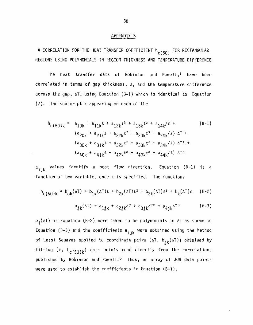
APPENDIX B
A CORRELATION FOR THE HEAT TRANSFER CQEFFICIENT hc(50) FOR RECTANGULAR
REGIONS USING POLYNOMIALS I N REGION THICKNESS AND TEMPERATURE DIFFERENCE
The heat t r a n s f e r da ta o f Robinson and Powell,6 have been
c o r r e l a t e d i n terms o f gap th ickness , L, and t h e temperature d i f f e r e n c e
across t h e gap, AT, u s i n g Equat ion ( R - 1 ) which i s i d e n t i c a l t o Equat ion
( 7 ) . The s u b s c r i p t k appear ing on each o f t h e
va lues i d e n t i f y a heat f l a w d i r e c t i o n . Equat ion ( B - 1 ) i s a a i j k f u n c t i o n o f two v a r i a b l e s once k i s s p e c i f i e d . The f u n c t i o n s
bi(AT) i n Equat ion (B -2 ) were taken t o be polynomia ls i n A T as shown i n
Equat ion (8-3) and t h e c o e f f i c i e n t s aijk were ob ta ined u s i n g t h e
o f Leas t Squares a p p l i e d t o c o o r d i n a t e p a i r s ( A T , b ( A T ) ) abl;ained by
f i t t i n g ( a 3 h c ( 5 0 ) k ) da ta p o i n t s read d i r e c t l y from the c o r r e l a t i o n s
pub l ished by Robinson and P ~ w e l l . ~ 'Thus, an a r r a y o f 309 data p o i n t s
were used t o e s t a b l i s h t h e c o e f f i c i e n t s i n Equat ion (6 -1) .
j k

The steps outlined above do not resu t i n a true leas t square f i t
C ( W o f the data s e t and was consequently checked by calculating h
values t o compare w i t h the i n p u t data. Table B-1 summarizes the results
o f the calculation. The average value for the difference between
values should be 0.6 for a l eas t squares cal cul ated and i n p u t h
f i t . The column headed A % contains the actual value for the average
for each heat percent difference between calculated and i n p u t h
f l o w direction. Table B - 1 also contains an average value for the
c(50)’ * ’ absolute value of the difference between calculated and i n p u t h
for each heat flow direction i n a column labeled 74, A 95%
was calculated Prom the confidence interval fo r each se t o f h
sample s tandard deviation o f values for A . Figure 8-1 shows the
as a function percentage differences between calculated and i n p u t h
are within of R. Approximately 94% of the 309 o f the calculated h,(50j
? 2% of the i n p u t values and 98% are w i t h i n t 32. Table 8-2 contains
using E q u a t i o n ( 7 ) o r Equation (B-1) the a i j k needed t o calculate h
and Table B - 3 contains typical output for each heat f l o w direction.
Table B-2 i s followed by f ive figures that show calculated h
plotted on the curves pub1 ished by Robinson and Powell . 6
c(50)
c(5W
c(50)
4 5 0 )
4 5 0 )
c(50)

38
Tab le 6-1. Summary of r e s u l t s ob ta ined f o r t he comparison o f c a l c u l a t e d and exper imenta l h
c ( W
95% Confidence QII
(b ) A ( % ) Heat Flow Number o f Di r e c t i o n P o i n t s % ( a 1 -fq-%
U P 65 - .0015 0.24 U P @ 45" 70 .0150 0.92 HORIZONTAL 65 - .0990 1.26 DOWN (3 45" 65 . ooao 0.39 DOWN 39 .0220 1.01
0.62 2.60 3.14 1.02 2.48

39
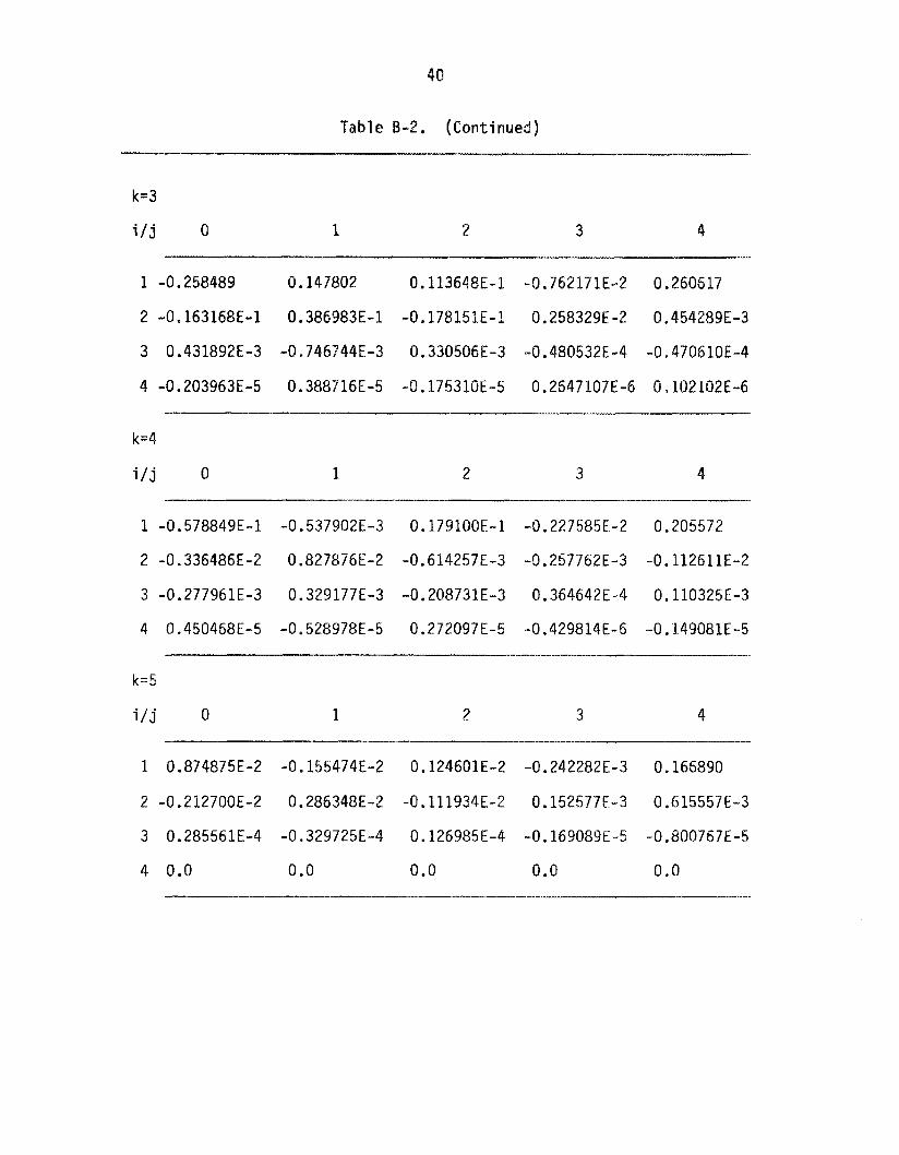
Table B-2. Coefficients a i jk fo r Equation 7
k
1
2
3
4
5
- Heat Flow Direction
UP
45O up
horizontal
45" down
down
k= 1
i / j 0 1 2 3 4
1 0.154033 0.1 28242 -0.672234E-1 0.103352E-1 0.449575E-1
2 0.261297E-1 -0.170819E-1 0.740205E-2 -0.106537E-2 -0.129284E-2
3 -0.543166E-3 0.484687E-3 -0.224020E-3 0.332463E-4 0.268733E-4
4 0.421073E-5 -0.427516E-5 0.205385E-5 -0.310975E-6 -0.122383E-6
k=2
i /j 0 1 2 3 4
1 -0.292974 0.439537 -0.155525 0.188638E-1 0,198930
2 0.248568E-1 -0.537916E-2 -0.247209E-3 0.207259E-3 -0.690024E-2
3 0.153549E-3 -0.536929E-3 0.260268E-3 -0.367985E-4 -0.197945E-4
4 -0.428586E-5 0.706284E-5 -0.308349E-5 0.412338E-6 0.104639E-5
40
Tab1 e B-2. (Conti nued)
k=3
i / j 0 1 2 a 4
1 -0.258489 0.147802 0.113648E-1 -0.762171E-2 0.260617
2 -0.163168E-1 0.386983E-1 -0.178151E-1 0.258329E-2 0,454289E-3
3 0.431892E-3 -0.746744E-3 0.330506E-3 -0.480532E-4 -0.470610E-4
4 -0.203963E-5 0.388716E-5 -0.175310E-5 0.2647107E-6 0,102102E-6
k=4
i / j 0 1 2 3 4
1 -0.578849E-1 -0.537902E-3 0.179100E-1 -0.227585E-2 0.205572
2 -0.336486E-2 0.82787SE-2 -0.614257E-3 -0.257762E-3 -0.112611E-2
3 -0.277961E-3 0.329177E-3 -0.20873lE-3 0.364642E-4 0.110325E-3
4 0.450468E-5 -0.5289786-5 0.272097E-5 -0.429814E-5 -0.l.49081E-5
k=5
i / j 0 1 2 3 4
1 0.874875E-2 -0.155474E-2 0.124601E-2 -0.242282E-3 0.166890
2 -0.212700E-2 0.286348E-2 -0.111934E-2 0.152577E-3 0.615557E-3
3 0.285561E-4 -0.329725E-4 0.126985E-4 -0.169089E-5 -0.800767E-5
4 0.0 0 .o 0.0 0.0 0.0

41
obta ined f rom Equatfan (1 ) c(50) Table 8-3. Resu l t s f a r h
computed us ing t h e aijk va lues 4 5 0 ) The f o l l o w i n g i s a t a b u l a t i o n o f h
1 i s t e d above:
k i d e n t i f i e s t h e d i r e c t i o n o f heat flow: 1 = heat f l o w up 2 = heat f low 45" up 3 = heat f l o w h o r i z o n t a l 4 = heat f l o w 45" down 5 = heat flow down
DT i d e n t i f i e s t h e temperature d i f f e r e n c e ( O F ) across a gap o f w i d t h x inches. The u n i t s f o r h a r e BTU/f t 2 ' h r O F. d 5 0 )
k = l 4 5 0 )
DT = 10.100 h
x = 0.500 1 .ooo 1.500 2.000 2.500 3.000 3.500
DT = 20.00 x = 0.500
1 .ooo 1.500 2 000 2.500 3 .QOO 3 .SO0
DT = 30.00 x = 0.500
1 .a00 1.500 2.000 2.500 3.000 3.500
DT = 40.00 x = 0.500
1.000 1 .500 2 .ooo 2.500 3 .OOO 3.500
0.432 0.391 0.369 0.353 0.341 0.332 0.330
0.526 0.476 0.448 0.429 0.416 0.406 0.400
0.587 0.535 0.505 0.483 0.468 0.457 0.450
8.630 0.578 0.546
0.506 a. 494 0.488
a. 523
DT = 50.00 x = 0.500
1.000 1,500 2.000 2.500 3.000 3.500
x = 0.500 1.000 1.500 2 .ooo 2.500 3 .OOO 3.500
DT = 60.00
0.669 0.613 0,581 8.557 0.538 0.526 0.519
0.717 0.651 0.616 0.592 0.574 0.560 0 e 550

42
Table €3-3, (Continued)
k = 2 ''*Oo hc(50) DT =
0.353 0.317
x = 0.500 1 .ooo 1,500 0.317 2.000 0.311 2.500 0,298 3.000 0.289 3 500 0.294
x = 0.500 0.422 1.000 0.397 1.500 0.390 2,000 0.378 2.500 0.365 3,000 0.356 3.500 0.361
x = 0.500 0.470 1 .ooo 0.454 1.500 0.439 2,000 0.425 2.500 0.414 3.000 0.409 3.500 0.412
x = 0.500 0.511 1 .ooo 0.497 1.500 0.474 2 .ooo 0.458 2.500 0.451 3 000 0.450 3.500 0.450
x = 0.500 0.547 1 .ooo 0.530 1 e 500 0 ., 503 2,000 0.487 2,500 0.483 3 + 000 0.483 3.500 0.480
x = 0.500 0.583 1,000 0.563 1.500 0.535 2.000 0.520 2 500 0.514 3.000 0.512 3.500 0.504
DT = 20.00
DT = 30.00
DT = 40 e 00
DT = 50 a 00
DT = 60.00
k - 3 DT =
x = 0.500 1 I000 1 .500 2 080 2.500 3.000 3.500
x = 0.500 1. OOQ 1.500 2.000 2.580 3.000 3.500
x = 0.500 1 .OOO 1.500 2.000 2.500 3.000 3.500
x = 0.500 1.000 1.500 2.000 2.500 3.000 3.500
x = 0.500 1.080 1.500 2 .ooo 2.500 3.000 3.500
x = Q.500
DT =
DT =
DT =
DT =
DP
1.000 1.500 2.000 2.500 3.000 3.500
l o a o o hc(50) 0.340 0.222 0 a 230 0.245 0,251 0 248 0.244
0.349 0.278 0.301 0.314 0.311 0.305 0.310
0.362 0.323 0.354 0 365 0 355 0 a 344 0.353
0.378 0.360 0.394 0.401 0.388 0.373 0.380
0,394 0.393 0.426 0.430 0.414 0.395 0.401
0.411 0 * 423 0 * 454 0.456 0.439 0.421 0.426
20 00
30.00
40 e 00
50.00
60.00

Tab1 e 8-3 e (Continued)
k - 4 DT = 10.00
x = 0.500 1,oao 1.500 2.000 2.500 3.000 3 3 0 0
DT = 20.00 x = 0.500
1 .ooo 1.500 2 .ooo 2.500 3.000 3.500
DT = 30.00 x = 0.500
1 .ooo 1.500 2.000 2.500 3.000 3.500
DT = 40.00
1 .ooo 1,500 2.000 2.500 3,000 3.500
DT = 50.00 x = 0.500
1,000 1 560 2.000 2.580 3.000 3.5630
DT = 60.00
1.000 1,500 2.000 2.500 3 000 3.500
x = 0.500
x = 0.500
hc(50) 0.346 0.191 0.166 0,168 0.176 0.181 0.180
0.344 0.217 0.211 0.221 0.229 0.230 0.224
0.348 0.241 0.248 0.261 0.265 0 262 0.256
0,354 0,263 0.277 0,289 0.289 0.282 0 279
0,361 0 284 0,301 0 312 0 308 0 298 0.295
0 365 0.302 0.322 0.331 0 e 326 0.314 0.308
k = 5 DT =
x = 0.500 1 .ooo 1.500 2.000 2.500 3.000 3.500
x = 0.500 1,000 1.500 2.000 2.500 3.000 3.500
x = 0.500 1 .ooo 1.500 2.000 2.500 3.000 3.500
x = 0.500 1.000 1.500
DT =
DT =
DT =
2.000 2.500 3.000 3.500
x = 0.500 1.000 1.500 2.000 2.500 3,000 3.500
x = 0.500 1.000 1.500
DT =
DT =
2looo 2.500 3.000 3,500
loa O0 hc( 50 1 0.345 0.179 0.125 0.098 0.082 0,071 0.064
0.347 0.182 0.130 0.103 0.087 0.077 0.071
0.349 0.185 0.134 0.108 0.092 0.082 0.077
0.351 5.188 0.137
20 00
30.00
40.00
0.112 0.096 0.086 0.082
50.00 0.353 0.191 0.140 0. 114 0.099 0 "089 0.086
0.355 0,193 0.142 0.116
60.00
0.101 0.091 0.088

44
C ( W F i g u r e B . 1 . A comparison of c a l c u l a t e d and experimental h
f o r hea t f l o w upward,

4 5
- COMPUTED VALUES
2----- - _ _ _ - _ _
4.00 i .50 2.00 2 30 3.00 3.50 0 0.50 AIR SPACE THICKNESS, I ,INCHES
c(50) Figure B.2. A comparison o f calculated and experimental h
f o r heat flw upward a t 45 deqrees.

4 6
TED VALUES
--
0 0.50 4.00 1.50 2.00 2.50 3.00 3.50 AIR SPACE THICKNESS, , INCHES
c (50 ) F i g u r e B.3. A comparison of c a l c u l a t e d and exper imenta l h
f o r heat f l o w h o r i z o n t a l .

47
ORNL - DWG 83 -44357
Q -COMPUfED VALUES
0 0.50 460 4.50 2 .oo 2.50 3.00 3.50 AIR SPACE THICKNESS, ,INCHES
4 5 0 ) F i g u r e 3.4. A comparison of c a l c u l a t e d and experimental h
f o r heat f lw dwnward a t 45 degrees.

48
ORNL-DWG 53 -44358
e -COMPUTED VALUES
Q 0.50 4.00 1.50 2 .00 2 3 0 3 .OO 3.50
AIR SPACE THICKNESS, 2 ,INCHES
Figure B.5. A comparison o f ca lcu la ted and exper imental h c ( 5 0 ) f o r heat f l o w downward.

APPENDIX C
FORTRAN PROGRAM FOR THE CALCULATION OF EFFECTIVE R-VALUE FOR A SERIES
OF PARALLEL REFLECTIVE A I R GAPS ~ ~-
Contents
c.1 Program d e s c r i p t i o n
c.2 Required i n p u t i n f o r m a t i o n
c.3 Program ou tpu t
c.4 L i s t i n g o f program REFLECT
C.5 Example o u t p u t f o r REFLECT
C.6 L i s t i n g o f REFLECT v e r s i o n 2
c.7 Example o u t p u t f o r REFLECT v e r s i o n 2

50
C . l Effective R-value ---. Calculation
The Fortran pragra "REFLECT" listed in t h i s appendix can be
used to calculate an effective R-value for a series of parallel air
gaps positioned between isothermal planes. The steady-state
one-dimensional calculation -includes heat transfer by radiation and
convection-conduction. Convective heat transfer coefficients are
taken from the data o f Robinson et a1.6 using the constants listed
in Appendix B.
C.2 The Program Requires the - Following Input
I tem
( a ) Heat f l o w direction
( b ) Number of air qaps
(c) Thickness of gap 1 (inches)
(d)
(e)
Emissivities f o r the two surfaces of gap I
boundaries ( O F )
Temperatures of the i sothermal
C . 3 The Program Outputs the Following Information
(a) Heat flaw direction and number o f air gaps
( b ) Thickness and E fo r each gap
(c) Temperatures on the boundaries o f each gap
( d ) Effective R-value for each air gap
(e ) Effective R-value for the total system

51
C.4 L i s t i n g o f Program REFLECT
c
&
& & 84 & & & & & & & 84 & & & & & 84 & & & & & & &
888
1
PROGRAM REFLECTIVE R DIMENSION X(10) ,E( 10) ,T( 11,2) ,DT( 10) ,TM( 10) ,R( lo), SE(10,2),TS(10) COMMON A(4,5 $5) DATA A /’ 0.154033 0.128242 ,-0.170819E-l, 0.484687E-3,-0.427516E-5, -0.672234E-1, 0.740205E-2,-0.22402OE-3, 0.205385E-5, 0.103352E-1,-0.106537E-2, 0.332463E-4,-0.310975E-6, 0.449575E-1,-0.129284E-Z, 0.268733E-4,-0.122383E-6, -0.292974 , 0.248568E-1 , 0,153549E-3 ,-0.428586E-5, 0.439537 ,-0.537916E-2,-0.536929E-3, 0.706284E-5, -0.155525 ,-0.247209E-3, 0.260268E-3,-0.308349E-5, 0.188638E-1, 0.207259E-3,-0.367985E-4, 0.412338E-6, 0.198930 ,-0.690024E-2,-0.197945E-4, 0.104639E-5 , -258489, -.163168E-1, .431892E-3,-.203963E-5, 0.147802 ,.386983E-1,-.746744E-3, 0.388716E-5, 0.113648E-1, -.178151E-1,0.330506E-3,-0.175310E-5, -0.762171E-2,0.258329E-2,-0.480532E-4,0.2647107E~6, 0.260617 0.454289E-3 ,-.470610E-4,0.102102E-6, -0.578849E-1,-0.336486E-2,-0.277961E-3, 0.450468E-5, -0.537902E-3, 0.827876E-2, 0.329177E-3,-0.528978E-5, 0.179100E-1,-0.614257E-3,-0.208731€-3, 0.272097E-5, -0.227585E-2,-0.257762E-3, 0.364642E-4,-0.429814€-6, 0.205572 ,-0.112611E-2, 0.110325E-3,-0.149081E-5, 0.874875E-2,-0.21270OE-Z, 0.285561E-4, 0,000000 ,
, 0.124601E-2,-0.111934E-2~ 0.126985E-4, 0.000000 ,
,0.261297€-1, -0.543166E-3,0.421073E-5,
-0.155474E-2 , 0.286348E-2 ,-0.329725E-4, 0 .OOOOOO
-0.242282E-3, 0.152577E-3,-0.169089E-5, 0.000000 0.166890 , 0.615557E-3,-0.800767E-5, 0.000000 i CONT I NU E WRITE( 5,100) WRITE( 5,101 1 READ(5,200) K WRITE(5,lOZ) READ(5,ZOO) N NP=N+l WRITE(5,103) K,N WRITE(5,104) DO 1 J=l,N READ(5,201) I ,X(I) ,SE( I ,1) ,SE( I ,2) E( I)=l.O/(l.O/SE( I,l)+l.O/SE( 1,2)-1.0) CONTINUE WRITE( 5,105) WRITE(5J06) (J ,X( J ) ,E( 3 ) ,J=1 ,N) WRITE( 5,107) READ (5,202) T( 1,l) ,T(NP,l) T(1,2)=T( 1,l)
XT=T(NP,l)-T( 1 3 1 )
xs=o .o T(NP ,Z )=T(NP , I

52
2
3 2 2 2
4
3 3 3
100 10 1 1 0 2 103 104
105 106 1 0 7 108 109 110 111 112 113 114 200
&
DO 2 I=1,N
CONTINUE DO 3 I=2,N T ( I , l ) = T ( 1-1 , l )+XT*X( I - I ) / X S CONTINUE CONTINUE SR=O * 0 DO 4 I = l , N TM( 1 ) = 0 . 5 * ( T ( I + l , l ) + T ( 1 , l ) )
HR=E(I )*0.00686*( ( T M ( I ) + 4 6 O , 0 ) / 1 0 0 . )**3 R(I)=l.O/(HR+HC(K,X( I ) , D T ( I ) , T M ( I ) ) ) SR=SR+R( I) CONTINUE DO 5 I=2,N
XS=XS+X ( I )
DT( I ) = A B S ( T ( I + l , l ) - T ( i , I , ) )
T ( I ,2)=R( I - l ) * X T / S R + T ( I-l,l) TS( I ) = A B S ( T ( I ,2 ) -T( I ,1)) CON? I NU E DO 6 I = l , N
CONTINUE WRITE( 5,108) WRITE( 5,109) W R I T E ( 5 , l l O ) ( I , T ( I , l ) 3 1 = 1 9 N P ) W R I T E ( 5 , l l l ) WRITE( 5 , 1 1 2 ) ( I ,R( I) ,TM( I) ,I=l ,N) WRITE(5,113) SR WRITE(5,114) GO TO 888 CONTINUE DO 7 I=2,N T( I , l ) = T ( I ,2) CONTINUE GO TO 222 FORMAT(ZX, ' PROB. TYPE 1=UP ,2=45/UP ,3=MOR,4=45/DOWN ,5=DOWN ) FORMAT( 2X, ' INPUT PROBLEM TYPE ( 1 2 ) ' ) FORMAT(ZX,'INPUT NUMBER OF A I R GAPS ( 1 2 ) ' ) FORMAT(ZX,'HEAT FLOW TYPE' , 1 Z 3 ' WITH' ,13,' GAPS') FORMAT(2X,'INPUT GAP NO. (12),WIDTH (F lO,3) ,S IDE 1 EM (F10.3) ,SIDE 2 EM ( F 1 0 . 3 ) ' ,/) FORMAT( ZX, ' GAP NUMBER W IDTW E VALUE' ,/) FORMAT(2X,I6,4X ,F10.3,4X ,F10.4) FORNAT(ZX,'INPUT TEMP L P SUR. (F10.3) , RT SUR. ( F 1 0 . 3 ) ' , / )
FORMAT( 2X, ' BOUNDARY TEMPERATURES ( F ) ' ,/) FORMAT ( 2X , I5 ,5X , F10.2 1 FORMAT(ZX,' GAP NUMBER R OF GAP T MEAN') FORMAT( 2X , I5,5X, F10.3,1X, F10.1)
FORMAT(ZX,'*********.*** END OF CALCULATION ************' FORMAT ( I 2 )
I F ( T S ( 1 ) .GT. l . E - 4 ) GO TO 333
FORMAT( zx , I CONVERGENCE HAS BEEN ACH I EVED
FORMAP(2X,' TOTAL R-VALUE FOR T H I S CASE IS ' ,F10.3,/) ,// )

53
20 1 FORMAT( 12,3F10.3) 202 FORMAT(2F10.3) 999 CONTINUE
END
FUNCTION HC(K,X ,DT,TM) COMMON A(4,5 , S ) I F ( X .GE. 0.5 ) GO TO 1 HC=0.159*( 1,0+.0016*TM)/X RETURN
1 HC=O. 0 DO 2 5=1,4 DO 2 I=1,4 HC=HC+A( I ,J ,K)*X**J*DT**I/(X*DT)
DO 3 I=1,4
C=O. 159*( 1.0+0.0016*TM)/X
IF ( W .GT. 10.0 1 GO TO 4
RETURN
RETURN END
C EFFECTIVE R-VALUE FOR A SERIES OF REFLECTIVE A I R GAPS
2 CONTINUE
HC=HC+A( I ,5 ,K)*DT**( I - l ) /X 3 CONT I NU€
W= ( HC-C ) * lOO/C
HC=HC*( 1.0+0.0017* (TM-50.0) 1 4 HC=HC*( 1.0+0.0010"(TM-50.0))

54
C.5 Example Output fat- REFLECT
PROB. TYPE 1=UP ,2=45/UP ,3=HOR ,4=45/DOWN ,5=DOW INPUT PROBLEM TYPE (12) 1 INPUT NUMBER OF A I R GAPS (12) 3 HEAT FLOW TYPE 1 WITH 3 GAPS
INPUT GAP NO. ( IZ ) ,WIRTH (F10.3),SIDE 1 EM (F10.3) ,SIDE 2 EM (F10.3)
1 3.75 .80 .05 2 1.0 80 .05 3 .75 .05 .80
GAP NUMBER WIDTH E VALUE
1 3.750 0.0494 2 1.000 0.0494 3 0.750 0.0494
INPUT TEMP LT SUR. (F10.3), RT SUR. (F10.3)
49.9 100.1 CONVERGENCE HAS BEEN ACHIEVED BOUNDARY TEMPERATURES (F)
1 49.90 2 68.57 3 84.70 4 100.10
1 2.266 59.2 2 1.958 76.6 3 1.869 92.4
GAP NUMBER R OF GAP T MEAN
TOTAL R-VALUE FOR THIS CASE IS 6 093

55
C.6 Listing of REFLECT' Version 2
The version o f REFLECT listed below has been constructed to
calculate R-values for k = 1, 2, 3 , 4, and 5 for a given set o f input
values fo r N, gap widths, emissivities, and total temperature difference
across the assembly. The function HC called by this version i s the same
a s HC in the preceding program.
c
1
PROGRaM REFLECTIVE R DIMENSION X ( 10) ,E( 10) ,T( 11,2) ,DT( 10) ,TM( 10) ¶R( l o ) , SE( 10 $ 2 ) ,TS( 10) COMMON A(4,5,5) DATA A / 0.154033 ,0.261297E-1, -0.543166E-3,0.421073E-5, 0.128242 ,-0.170819E-l, 0.484687E-3,-0.427516E-5, -0.672234E-1 , 0.740205E-2 ,-0.224020E-3, 0.205385E-5 0.103352E-1,-0.106537E-2, 0.332463E-4,-0.310975E-6, 0.449575E-1,-0.129284E-ZB 0.268733€-4,-0.122383E-6, -0.292974 , 0.248568E-1, 0.153549E-3,-0.428586E-5, 0.439537 ,-0.537916E-2,-0.536929E-3, 0.706284E-5, -0.155525 ,-0.247209E-3, 0.260268E-3,-0.308349E-5, 0.188638E-1, 0.207259E-3,-0.367985E-4, 0.412338E-6, 0.198930 ,-0. 690024E-2 ,-0 .197945E-4 , 0.104639E-5 -.258489, -.163168€-1, .431892E-3,-.203963E-5,
0.113648E-1, -.178151E-1,0.330506E-3,-0.1753lOE-5, -0.762171E-2,0.258329E-2,-0.480532E-4,0.2647107E-6~ 0.260617 0.454289E-3 ,-.470610E-4 ,O. 102102E-6, -0.578849E-1,-0.336486E-2,-0.277961E-3 9 0.450468E-5 , -0.537902E-3, 0.827876E-2, 0.329177E-3,-0.528978E-5, 0.179100E-1,-0.614257E-3 ,-0.208731E-3, 0.272097E-5 9
-0.227585E-2,-0.257762E-3, 0.364642E-4,-0.429814€-6, 0.205572 ,-0.112611E-2, 0.110325E-3,-0.149081E-5, 0.874875E-2,-0.21270OE-2, 0.285561E-4, 0.000000 , -0.155474E-2, 0.286348E-2,-0.329725E-4, 0.000000 , 0.124601E-2,-0.111934E-2, 0.126985E-4, 0.000000 , -0.242282E-3, 0.152577E-3 ,-0 .169089E-5, 0.000000 , 0.166890 , 0.615557E-3,-0.800767E-5, 0.000000 /
0.147802 ,,386983~-1,-.746744~-3, 0.3aa716~-5,
CONTINUE WRITE(5,lOO)
READ( 5,200) N NP=N+l WRITE(5,104) DO 1 J=l,N READ(5,201) I,X(I),SE(I,l),SE(I,2)
CONTINUE
WRITE( 5,102)
E( I)=~.o/( ~.o/sE( I ,~)+I.o/sE( I ,2)-1.0)

5
2
3 222
4
10
333
7
100 10 1 102 103 104
p1
WRITE(5,105) WRITE( 5,106) (J $X(J) ,E(J) ,J=I ,N) WRITE(5,107) READ (5,2021) T(~,~),T(NP,I) T ( 1,2)=T( 1,l) T( NP ,2 )=T( NP ,I. ) XT=T( NP ,l ) -T( 1,l I . . - . xs=o*o XS=XStX( I) DO 2 I=l,N
CONTINUE DO 10 K=1,5 WRITE(5,103)K,N DO 3 I=2,N T( I ,i >=T( I -1 ,i )+XT*X ( I-I)/XS CONTINUE CONTINUE SR=O. 0 DO 4 I=l,N TM( I)=O.5*(T( I+l,l)+T( I ,1))
HR=E ( I ) *0.00686* ( (TM( I )+460,0 )/ 100. )**3
SR=SR+R( I) CONTINUE DO 5 I=2,N
DT( I)=ABS(T( It1 ,l)-T(1 ,1))
R ( I = 1.01 ( HR+HC ( K , x ( I , DT ( I 1 ,TM ( I
P( I , 2 ) = R ( I-I)*XT/SR+T( I-l,l) T~(I)=AB~(T(I,z)-T(I,~)) CONTINUE DO 6 I=1,N IF ( TS(I) .GT. l.E-4 ) GO TO 333 CONTINUE WRITE(5,108) WRITE( 5,109 ) WRITE(5,llO) ( 1 ,T( I ,1) ,I=l ,NP) WRITE(5,lll) WRITE(5,IlZ) ( I,R(I),TM(I),I=l,N) WRITE(5,113) SR CONTINUE WRITE(5,114) GO TO 888 CONTINUE DO 7 I=2,N T( I ,l)=T( I ,2) CONTINUE GO TO 222 FOKMAT(ZX, 'PROB. TYPE 1=UP,2=45/UP,3=H0Ry4=45/DOWN ,5=DOldN' ) FORMAT( 2X, ' INPUT PROBLEM TYPE ( 12) FORMAT(ZX, ' INPUT NUMBER OF AIR GAPS (12) ' ) FORMAT(2X,'HEAT FLOW TYPE' ,12,' WITW',13,' GAPS') FORMAT(2X,' INPUT GAP NO. (I2),WIDTH (F10.3),SIDE 1 EM (F10.3) ,SIDE 2 EM (F10*3)' ,/)
)

57
105 106 107 108 109 110 111 112 113 114 200 201 202 999
c.7
FORMAT( 2X, GAP NUMBER WIDTH E VALUE' ,/) FORMAT( 2X, 16,4X ,F10. 3,4X ,FlO.4) FORMAT(ZX,'INPUT TEMP LT SUR. (F1Q.3), RT SUR. (F10.3) ' , /) FORMAT( 2X CONVERGENCE HAS BEEN ACHIEVED ' FORMAT( 2X, FORMAT ( 2 X , I 5 ,5X , F 10.2 ) FORMAT(ZX, ' GAP NUMBER R OF GAP T MEAN') FORMAT( 2X, I5,5X ,F10.3 , l X ,F10. 1 )
FDRMAT(2X, I************ END OF CALCULATION ************I ,//) FORMAT ( I 2 ) FORMAT( I2,3F10.3) FORMAT( 2F10.3) CONT I NUE END
BOUNDARY TEMPERATURES (F ) ' ,/)
FORMAT(2X,' TOTAL R-VALUE FOR THIS CASE I S ',F10.3,/)
Example Output fa r Vers ion 2 o f REFLECT
PROB. TYPE l=UP,2=45/UP,3=HoR,4=45/DOWN,5=DOWN INPUT NUMBER OF A I R GAPS (12) 2
INPUT GAP NO. (€2),WIDTH (FlQ.3),SIDE 1 EM (F10.3) ,SIDE 2 EM (F10.3)
1 1.75 .9 .05 2 1.75 .05 .90
GAP NUMBER WIDTH E VALUE
1 1 750 0 0497 2 1 e 750 0,0497
INPUT TEMP LT SUR. (F10.3), RT SUR. (F10.3)
50. 100. HEAT FLOW TYPE 1 WITH 2 GAPS
CONVERGENCE HAS BEEN ACHIEVED BOUNDARY TEMPERATURES ( F )
1 50.00 2 75 .35 3 100.00
1 1.906 6 2 * 7 2 1.853 87.7
GAP NUMBER R OF GAP T MEAN
TOTAL R-VALUE FOR T H I S CASE IS 3.760

58
HEAT FLOW TYPE 2 WITH 2 GAPS CONVERGENCE HAS BEEN ACHIEVED BOUNDARY TEMPERATURES (F )
1 50.00 2 75.37 3 100.00
GAP NUMBER R OF GAP 1 2
2.147 2.084
TOTAL R-VALUE FOR T H I S
T MEAN 62.7 87.7
SE IS 4. 32
HEAT FLOW TYPE 3 w i t h 2 GAPS CONVERGENCE HAS BEEN ACHIEVED BOUNDARY TEMPERATURES ( F )
1 50.00 2 75.37 3 100.00
1 2 542 62.7 2 2.468 87.7
GAP NUMBER R OF GAP T MEAN
TOTAL R-VALUE FOR T H I S CASE IS 5.010
HEAT FLOW TYPE 4 WITH 2 GAPS CONVERGENCE HAS BEEN ACHIEVED BOUNDARY TEMPERATURES ( F )
1 50.00 2 75.42 3 100.00
1 3.448 62.7 2 3.334 87.7
GAP NUMBER R OF GAP T MEAN
TOTAL R-VALUE FOR T H I S CASE IS 6.781
HEAT FLOW TYPE 5 WITH 2 GAPS CONVERGENCE HAS BEEN ACHIEVED BOUNDARY TEMPERATURES ( F )
1 50.00 2 75.70 3 10O.OO
1 5.964 62.8 2 5.639 87.8
GAP NUMBER R OF GAP T MEAN
TOTAL R-VALUE FOR T H I S CASE IS 11.603

59
ORN L / TM -889 1
INTERNAL DISTRIBUTION
31-2. 3.
4-5. 6. 7. 8. 9.
10. 11. 12 * 13. 14. 15
16-18. 19.
Central Research Library 20 * Document Reference Sec t ion 21. Laboratory Records Department 22. Laboratory Records, ORNL RC 23. ORNL Pa ten t Sec t ion 24. E . E. Bloom 25. R. 6. Braid 26-30. R. S . Carlsmith 31 I )
J , A. Carpenter 32. c. V . Chester 33. K. W. Chi lds 34. J . E. C h r i s t i a n 35. G. E . Courv i l l e 3 6 , F. R. Cox 37-41. F. A. Creswick
EXTERNAL DISTRIBUTION
42. 43. 44. 45. 46.
47. 48. 49. 50 51.
52. 53" 54. 55.
56. 57 I
58 a
59.
60. 61. 6 2 .
W, Fulkerson T. G. Godfrey V , 0. Haynes S. I . Kaplan M . A. Karni tz T. S. Lundy M. C , Matthews D. L . McElroy J . W . Michel W . R. Mixon M. W. Rosenthal A. C. Schaffhauser H, 6. Shapira D. W. Yarbrough
P. R. Achenbach, 1322 Kurtz Road, Mctean, VA 22101 M. A. Albers , Manvil le , P. 0. Box 5108, Denver, CO 80217 E. L . Bales , Haines Lundberg Waeh'ler, New York, N Y 20036 J . Barnhart , TIMA, M t . Kisco, NY 10549 R. 3. Berg, Veterans Adminis t ra t ion (0815) Washington DG
J. R. B l a s i u s , HJH Chemicals, Tnc., Phoenix, Ai! 85034 PI. Bomberg, NRC-C, Ottawa, Canada R. J. Booth, DOMTAR Inc . , C.P. 300, Sennev i l l e , Quebec, Canada J . J . Boul in , D O E / C E , Washington, DC 20585 E . Brendeng, D i v a o f R e f r i g e r a t i o n Engineer ing, The Norwegian
8. Bromley, Spring Hope Rockwool, Inc . , Spring Hope, NC 27882 J. Cable, Architect, 510 Fontaiine S t . , Alexandria , V A S. H. Cady, MIMA, Summit, NJ 07901 P. A. Chandler, Al l fed F ibe r s II P l a s t i c s , Pe te rsburg , VA
20420
K1A OR6
I n s t i t u t e o f Technology, Trondheim, Norway
23834 V . R. Canf i e ld , GAF Corpora t ion , So. Bound Brook NJ 08880 P. A. Chandler, A l l i e d F ibe r s & P l a s t i c s , Petersburgh, VA
F. Cis tone , ARC0 Chemical Co., Ph i l ade lph ia , PA 19073 R. W. Cole, New Mexico Energy I n s t i t u t e , Albuquerque, NM
H. Coleman, D O E , Washington, DC 20585 R . Cornel iussen, Drexel Un ive r s i ty , Ph i l ade lph ia , PA 19104 K. G. Coumou, Dynatech R / D Company, Cambridge, MA 02139
23834
87 108

63 * 64 65. 66 a
67.
68. 69. 70. 71. 72. 73.
74.
75. 76 . 77. 78.
79.
80. 81. 82 *
83. 84.
8 5 . 8 6 . 8 7 .
88.
89 e
90. 91 .I
92 a
93.
94.
95 a
96 e
97.
98. 99.
R. Crenshaw , Lawrence Berkel ey Laboratory, Berkeley , CA 94320 G. R. Cunningbarn, General E l e c t r i c Go. Tacoma, MA G. M. Da l ton , F ibe rg las Canada LTD, Ontar io , Canada W. D 'Netto, F ibe rg las Canada, Inc , Sarnia, Ontar io , Canada
F. De Ponte, I n s t i t u o de F iska Technisa, Via Marzolo, Y - I
A. D e s j a r l a i s , Dynateeh R/D Company, Caiiibridge, MA 02139 M. W. D i zen fe ld , \.IUD, Washington, DC 20410 D. Downs, Cer ta in teed Corp,, P. 0. Box 1967, Athens, GA 30603 E. Dumi t r i v , Knauf F ibe rg las Co. , S h e l b y v i l l e , I N 46142 W. P. E l l i s , M . 14, F u l l e r Co., Sp r ing House, PA 19477 F. England, Simplex Housing I n t . 1301 Dade Blvd., Miami Beach,
P. W. Fa i rey , 111, F l o r i d a S o l a r Energy Center, Cape
A. E. F i o r a t o , P o r t l a n d Cement Assn., Skokie , IL 60077 E. C. Freeman, DOE/CE, Washington, DC 20585 U. Equchi , B.R. I. Tsukuba, Japan M. Francois E c o l e Polytechnique U n i v e r s i t e De Montreal , P. Gerard, P i t t s b u r g h Corning Europe, I n d u s t r i e Park 398
W . Gerken, DOE/CE, Washington, DC 2 0 5 8 5 R. Gerr ish, P i t t s b u r g h Corning Corp., P i t t sbu rgh , PA 15239 5. F. Gi l rnar t i r i , Owens-Corning F ibe rg las , Washington, BC
L. R. Glicksman, MIT, Cambridge, MA 02139 W . P. Goss, Mech. Engr. Dept., U n i v e r s i t y o f Mass., Amherst,
F. A. Govan, Z i e l Blossom & Associates, C i n c i n n a t i , OH 45202 D. M. Greason, Dow Chemical U.S.A., G r a n v i l l e , OH 43023 R. A. Grot , Na t iona l Bureau o f Standards, Washington, DC
N . E. Hager, Jr. , Armstrong World I n d u s t r i e s , Inc. , R&D,
J . D. Hansen, U.S. Gypsum, L i b e r t y v i l l e , I L 60048 R. L. Hauser, Hauser Lab., Boulder, CO B. Heckley, Dow Chemical Canada, Inc., Modeland Rd., Sarnia
,I L. Weldenbrand , Nat iona l Bureau o f Standards, Washington , M. Ho l l i ngswor th , Owens-Corning F ibe rg las Corp. G r a n v i l l e ,
K. C. Howerton, Federal Trade Commission, Washington, DC
N. Hughes, D O E , Washington, DC 20585 J . G. Hust, Na t iona l Bureau o f Standards, Boulder, CO 80303 P. J . J u l i a n , B u i l d i n g Products o f Canada, 0244 S t . P a t r i c k
P. F. Juneau, A l f o l , Inc. , P.O. Box 7024, Char lo t te , NC 28217 A. G. Kantsios, Langley Research Lab, NASA, Hampton, VA
N7T 7M6
35100 Padova, I t a l y
F I.
Canaveral, FL 32920
Montreal , Quebec, Canada
Tessenderl o , Belgium
20006
MA 01003
20234
Lancaster, PA 17604
On ta r io , Canada
DC 20234
OH 43023
20580
S t r e e t , LaSal le, Quebec, Canada H84 1R8

100.
101. 102.
103.
104. 105. 106. 107.
108.
109. 110.
111. 112.
113.
114. 115. 116,
117.
118.
119. 120. 121.
122. 123. 124. 125.
126.
127 . 128.
129.
130.
131. 132. 133.
R. A. Kingsbury, lsnderwri ters Lab. , Inc. Northbrook, IL
S. K l a r s f e l d , I sove r St., Gobain CRIR, 60290 Rantigny, France W. Kle in fe lde r , Underwri ters Labora to r i e s , Inc . , Northbrook,
L . Kremer, Warnock Hersey Profess iona l Se rv ices , Gnaissauga ,.
D. lamb, TVA, Chattanooga, TN 37401 D. C. Larson, Drexel Unive r s i ty , Ph i l ade lph ia , PA 19104 W . Linander , EURIMA, Roski lde, Denmark T. Lesuen, Graham F ibe rg la s s l t d . , 300 Main S t r e e t , Erin,
E. L. Marvin, Headquarters , Department of Army, Washington, DC
D. J . McCaa, Ce r t a in t eed Corp,, Blue Bell, PA 19422 P. E . McNall, National Bureau of S tandards , Washington, DC
3. T. M i l l e r , GSA, Washington, DC 20406 R. G. Miller, Jim Walter Research Corp., S t . Pe te rsburg , FL
W . V . Miller, C iv i l Engineering Laboratory, Po r t Hueneme, CA
J . P. Millhane, D O E / C E , Washington, DC 20585 M. Milne, U C L A , Los Angeles, CA 90024 Y. Miyake, EKO Instruments Trading Co. Ltd . , 151 8-21
D. E. Morgenroth, Owens-Corning F ibe rg la s , 27880 White Road,
J . Mumaw, Owens Corning F i b e r g l a s , P.O. Box 415, Granv i l l e , OH
R. Newbold, Oregon DOE, Salem, OR 97310 W . R . Newton, TVA, Chattanooga, TN 37401 T. J . Ohlemi l le r , National Bureau o f Standards , Gai thersburg ,
R. E . Oliver, DOE/CE, Washington, DC 20585 R. Or l and i , W . R. Grace & Company, cambridge, MA 02140 C . M. Pelanne, 4900 Pinyon Drive, L i t t l e t o n , CO 80123 E. Perrine, Wiss, Janney, Elstner & ASSOC. , Northbrook, IL
J . Pike, Knauf F i b e r g l a s , 240 El izabe th S t . , S h e l b y v i l l e , IN
H. Poppendiek, Geoscience Ltd. , Solana Beach, CA 92075 F. J . Powell, National Bureau o f S tandards , Gai thersburg , MD
B. Rennex, NBS, Bldg. 226, 6114, Dept. of Commerce,
W . E. Saver , Koppers Co., Inc. Science & Technology Center
E . Scha f fe r , Fo res t Products Laboratory, Madison, WI 53705 M. Schuetz , MIT, Cambridge, MA 02139 A. Schumann, Owens-Corning F ibe rg la s Corp., G r a n v i l l e , OH
60062
IL 60062
Ontar io , Canada
Ontar io , Canada
20310
20234
33702
93043
Hatagaya-2 Shibuya Tokyo, Japan
Perrysburg , OH 43551
43023
MD 20234
60062
46176
20234
Washington, DC 20234
Monrovi l le , PA 15146
43023

M
0
M
"5
n
-F
b
-I-
o>
fa B
5
S
c)
r;
w n
3
P
UJ Y
b a In
rd L C
B
7.
OQ
EL
CO
U
V
Q)
kX
0
rcv
07
.P
ru -1
QI
I-- W
Y L a
a2 aJ W
!=
Q
J L
z -I
P
a s 0
w
(B z
-r-
L
ru
.. EZ
v
m
d
c3
4

63
170. T, B. Massalski (Consultant), Dept. of Metallurgy and Materials Science, Garnegie-Me? lon University, 5000 Forbes Street, Pittsburgh, PA 15213
171. R. H. Redwine, Kilnble Products Division, Owens-Illinois, Inc . , One Sea Gate, Toledo, OH 43666
172. J. C. Williams (Consultant), Mellon Institute, Carnegie-Mellon University , 5000 Forbes Street Pittsburgh, PA 15213
173. K. M. Zwilsky (Consultant), National Materials Advisory Board, National Academy o f Sciences, 2101 Constitution Avenue, Washington, DC 20418
174. Office o f Asst. Manager for Energy Research and Development, DOE-ORO, P.O. Box E, Oak Ridge, TN 37830
175-201. Technical Information Center, Oak Ridge, TN 37830