Embed Size (px)
Citation preview

7´
10´ 20´
9.5´
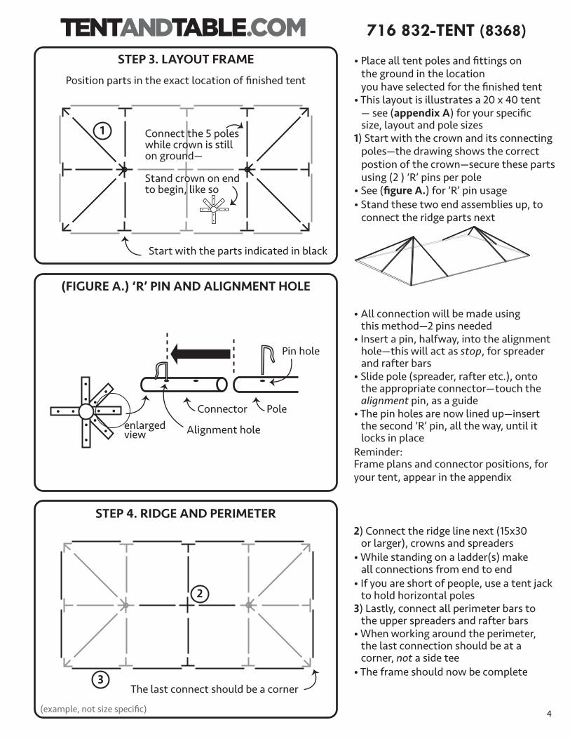
WEST COAST FRAME TENT
10 ́x 20´A S S E M B L Y I N S T R U C T I O N S

716 832-TENT (8368)
1
Refer to (appendix) for basic spreader, rafter and fitting layout
West Coast Frame Tent (OVERVIEW)
West Coast Frame Tent (SPECIFICATIONS: 10x20)
(example, not size specific)
Canopy
Crowns
Spreader Bar
Corner Fitting
Hip Rafter
Leg Pole
Side Tee
Base Plate
Ratchet Rope
Pole and Bar Diameter:
2˝O.D. 1.75˝I.D.
Sidewalls (optional)
Anchoring Stakes
Width 10 ft. / 3.0m Length 20 ft. / 6.1m Area 200 ft² / 18.3m² Eave Height 7' / 2.1m (opt. 8'/ 2.4m) Overall Height 9' 6" / 2.9m (opt. 10.6'/ 3.2m) Pitch 2' 6" / .8m Complete Weight 306 Lbs./139 Kg. (312 Lbs./142 Kg.) Series West Coast Class FrameCenter Pole No Style / Shape Traditional Tent Expandable No (sectional tops only)
Custom Printing Available Yes
Fabric Material PVC Coated PolyesterFabric Material Weight 16 oz. / yd2 / 540 gsmFabric Translucency Block-out Water Repellency Waterproof Flame Resistant Yes UV Resistant Yes Mold and Mildew Resistant Yes Frame / Pole Material AluminumLongest Component 9'4" / 2.8m Persons required for setup 2–4 Occupancy 20 Sit Down Dinner Occupancy (cont.) 33 Cathedral Seating
STEP 1. CHECK ITEM LIST (10ft. x 20ft.)
Item Illustration (all parts available for replacement) Size Quantity
10x20 4
10x20 2
10x20 7
10x20 6
10x20 4
10x20 2
none
none
none
10x20 2
10x20 6
10x20 38
10x20 6
10x20 1
Hip Rafters(yellow/red)
Rafters(green/red)
Spreaders(white/red)
Leg Poles Base(black) Plates
Corner Fittings
Side Tee Fittings
6-Way Crowns
8-Way Crowns
Ridge Crowns
(Crowns)
Rope- 12ft., w/ loop
‘R’ Pins
Single Head Stakes(3/4˝x 30˝)
Canopy Top
SKU: BT-TAROPE
SKU: BT-FWCRN
SKU: BT-FWAST082
SKU: BT-FWAST080
SKU: BT-FWAST112
Size: 9 -́4˝(white)
Size: 6 -́10˝(yellow)
Sizes: 6 -́8˝(brown)SKU: BT-FWBP
SKU: BT-FWRP25
SKU: BT-34SH30
SKU: BT-FW12WTT
SKU: BT-FW4WST
3-WAY CROWNSKU: BT-FW3WC
SKU: BT-FWAST059
Size: 4 -́11˝(green)
(see appendix for more info)
2
716 832-TENT (8368)

STEP 1. CONTINUED
• When building or assembling anything above shoulder height, wear a hard hat• Steel toe boots are recommended• Inspect the site, look for overhead and underground obstructions— such as utilities • Call your local utility to have utility lines marked (call 3–5 days ahead)— call811.com is a good resource— ‘click’ 811 in Your State• Inspect all ropes and tie lines• Inspect poles, making sure there are no bends or breaks• Replace or repair any items in poor condition
STEP 2. SAFETY CHECK LIST
Tent Size QuantityRecommended Tools
10 x 10 none10 x 20 none15 x 15 none15 x 30 220 x 20 none20 x 30 220 x 40 320 x 60 4
SKU: WCF-JACK-12SKU: K-DE-D25980K
WARNINGTent products are manufactured for use as temporary structure and do not meet structural code, unless specified. Since weather is unpredictable, the customer must incorporate their own good judgment, common sense & knowledge of local conditions with the installation instruction guidelines. The customer is responsible to anticipate weather severity for proper time and method of construction.
‘BEFORE YOU DIG’ (hammer stakes)By Law you are required to contact your local “Call before you dig” number before you plan to dig. After calling, your local utility company will mark the location of underground utility lines. Laws from state to state vary on how far in advance you must call.Planning ahead and checking with your state’s program is always a smart idea. Failure to obtain a line location before digging can result in a substantial fine. Please find your local “call before your dig number” by going to call811.com.
This item is very important in the process, Frame Tent Jack (sold separately).Some West Coast Frame tents require frame tent jacks—and larger tents require multiple jacks.General rules are; work on the long side,one side at a time, and never place jack in the middle of a spreader bar.(set-up and use can be found on internet)
• 6ft. step ladders• Sledge Hammer• Tape Measure• Work boots• Stake Driver (for larger tents)
Estimated
3
716 832-TENT (8368)
4
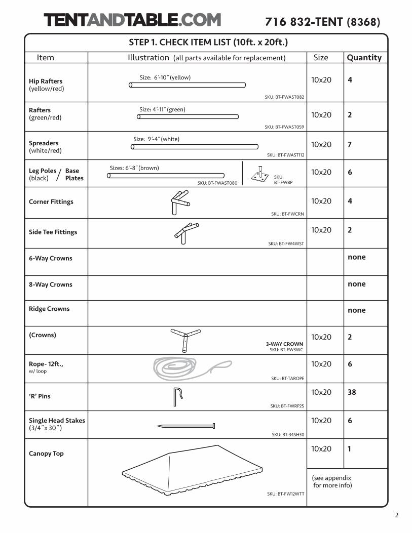
• Place all tent poles and fittings on the ground in the location you have selected for the finished tent• This layout is illustrates a 20 x 40 tent — see (appendix A) for your specific size, layout and pole sizes1) Start with the crown and its connecting poles—the drawing shows the correct postion of the crown—secure these parts using (2 ) ‘R’ pins per pole• See (figure A.) for ‘R’ pin usage• Stand these two end assemblies up, to connect the ridge parts next
• All connection will be made using this method—2 pins needed• Insert a pin, halfway, into the alignment hole—this will act as stop, for spreader and rafter bars• Slide pole (spreader, rafter etc.), onto the appropriate connector—touch the alignment pin, as a guide• The pin holes are now lined up—insert the second ‘R’ pin, all the way, until it locks in placeReminder:Frame plans and connector positions, for your tent, appear in the appendix
2) Connect the ridge line next (15x30 or larger), crowns and spreaders• While standing on a ladder(s) make all connections from end to end• If you are short of people, use a tent jack to hold horizontal poles3) Lastly, connect all perimeter bars to the upper spreaders and rafter bars• When working around the perimeter, the last connection should be at a corner, not a side tee• The frame should now be complete
(FIGURE A.) ‘R’ PIN AND ALIGNMENT HOLE
STEP 4. RIDGE AND PERIMETER
enlargedview
Connector Pole
Alignment hole
Pin hole
STEP 3. LAYOUT FRAME
Position parts in the exact location of finished tent
Start with the parts indicated in black
Connect the 5 poleswhile crown is still on ground—
Stand crown on endto begin, like so
The last connect should be a corner
1
2
3
716 832-TENT (8368)
(example, not size specific)
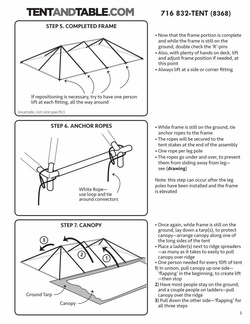
• Now that the frame portion is complete and while the frame is still on the ground, double check the ‘R’-pins• Also, with plenty of hands on deck, lift and adjust frame position if needed, at this point• Always lift at a side or corner fitting
• While frame is still on the ground, tie anchor ropes to the frame• The ropes will be secured to the tent stakes at the end of the assembly• One rope per leg pole• The ropes go under and over, to prevent them from sliding away from leg— see (drawing)
Note: this step can occur after the legpoles have been installed and the frameis elevated
STEP 6. ANCHOR ROPES
STEP 5. COMPLETED FRAME
• Once again, while frame is still on the ground, lay down a tarp(s), to protect canopy—arrange canopy along one of the long sides of the tent• Place a ladder(s) next to ridge spreaders —as many as it takes to easily to pull canopy over ridge• One person needed for every 10ft of tent1) In unison, pull canopy up one side— ‘flapping’ in the beginning, to create lift —then stop2) Have most people stay on the ground, and a couple people on ladders—pull canopy over the ridge3) Pull down the other side—’flapping’ for all three steps
STEP 7. CANOPY
If repositioning is necessary, try to have one person lift at each fitting, all the way around
Canopy
Ground Tarp
White Rope—use loop and tie around connectors
5
21
3
716 832-TENT (8368)
(example, not size specific)

Baseplate
Connect all the baseplates to the leg poles
at the bottomof each leg poleyou’ll findone hole
• For smaller tents, (10x10, 10x20, 15x15, 20x20) three or four people should be able to raise the frame and install the leg poles• Locate one of the long sides of the frame—this will be raised first, while the opposite side remains on the ground• Important: Lift the entire side of the frame at once (not one corner)• Install all the legs on this side—secure with ‘R’ pins—• Repeat for opposite side, then install legs for the remaining two sides• Double check the canopy corners—pull them down tight and straight• Important: tighten spring buckle straps— for security and to help pull canopy corners into place
STEP 10. INSTALLING LEGS (smaller tents)
6
Remember, baseplates should be attached first
Velcro corners together
• After canopy is pulled over frame and and corners are pulled into position, velcro corner seams together, loosely— tighten after legs are installed• The canopy should be attached to the frame, before legs are connected— secure some of the spring buckle straps, to keep canopy in place— start near corners and center fittings • Spring buckle straps are located on the underside of canopy• Secure the remaining straps after legs are installed on one side and secure— it’s easier at this height— Final tightening happens after legs are installed (step 10)
STEP 8. CANOPY CORNERS
Under canopythere will be several SpringBuckle Straps
Start with one at each corner and center fittings
• Before the tent is raised, prepare the leg poles• Place poles on top of base plate and secure with ‘R’ pins• Do this for all the leg poles
STEP 9. BASE PLATES
716 832-TENT (8368)

• For larger tents, (15x30 and larger) frame tent jacks should be used to raise the frame and install the leg poles• Locate one of the long sides of the frame—this will be raised first, while the opposite side remains on the ground• Important: Lift the entire side of the frame at once (not one corner)—crank jacks in unisonGeneral rules are; work on the long side,one side at a time, and never place jack in the middle of a spreader bar • Install all the legs on this side—secure with ‘R’ pins• Repeat for opposite side, then install legs for the remaining two sides• Important: tighten spring buckle straps— for security and to help pull canopy corners into place
Double check leg poles—making sure each pole is straight and lined up correctly, while tent jacks are still handy• Once the tent is vertical and all the leg poles are attached, begin the process of staking the tent—with plenty of hands on deck, lift and adjust tent position if needed, first• Measure 4 ft. out from each leg pole and place a stake in the ground• Stakes should look uniform, around the tent—and 6 inches above ground see (figure B)• Stakes should then be hand hammered or for larger installs, use a stake driver
STEP 11. STAKE LINE
Leave 6 inches showing
Correct Incorrect
STEP 10. INSTALLING LEGS (15x30 and larger tents)
• Ground stakes should be hammered in vertical, not angled (sledge hammer required)• Complete the hammering process by driving the stakes in and leaving 6 inches showing• Connection of ropes to ground stakes, can be made with a few different secure knots (see figure C, page 8) for one of the more commonly used knots
(FIGURE B.) HAMMERING STAKES
Remember, baseplates should be attached first
6˝
Stake Line
GroundStakes
Approx. 4 to 5ft.from leg poles
4 ft.
4 ft.
7
20 x 40 example
716 832-TENT (8368)
(example, not size specific)

3.) 4.)
1.)
2.)
10´
10´
10´
6´-8˝
• A commonly used knot for securing a rope to stake is the clove-hitch1.) Make two loops2.) Cross loops by placing second loop over the first3.) Place the combined loops over stake Option: loops can be form directly on stake4.) Pull on both ends to tighten rope Note: outward force tightens and inward force loosens the knot—when making adjustments5.) Excess line should be pulled half- way up the rope and tied off
(FIGURE C.) CLOVE-HITCH KNOT
Anchor Ropesshould be tight
One rope per leg pole
Position corner strapsstraight off corner pole
• As the assembly nears completion it is time to tighten all ropes/ratchet straps• Keep an eye any lean that might be caused by the tightening process• Go around the tent, make adjustments for any leg pole and tent lean• Smaller tents use ropes to secure the tent to the stakes— see (figure C)• Finally, secure any remaining spring buckle straps, under the canopy, that were not secured in step 8
STEP 12. SECURING ROPES
8
FINISHED TENT (10x20)
716 832-TENT (8368)

9
716 832-TENT (8368)
D. E.
WIND AND RAIN – IMPORTANT INFORMATION:WIND!Wind can cause the ratchet assemblies and stakes to loosen, or cause the poles to sink or shift through constant movement and vibration — the tension of the tent will be negatively altered.Follow these steps to provide extra security and safety during windy conditions: • Very important, do routine maintenance checks — be sure to check proper tension regarding the ratchet assemblies, throughout the day/event. This is critical, if your tent must stay up, in moderate windy conditions. • In the case of strong winds, remove any sidewalls. This will allow the wind to pass through the tent, diminishing major upward pressure on the tent top.• Additional security can be achieved by adding additional stakes and ropes/straps to corners— and to the ‘wind side’ of the tent.• When anticipating windy conditions, perform a soil test to determine proper staking: 1.) drive a large steel stake approx. 20 in. into soil, vertically 2.) measure the distance from the ground to the top of stake 3.) with a 16lb. sledge hammer, strike stake with an average blow (don’t over hit) 4.) measure the movement/hold strength: (0.2in./2500lbs) (0.3–.5in./1600lbs) (0.6–1.5in./800lbs) (1.6–3in./400lbs) (3–6in./200lbs) (> 6in./100lbs) Double or triple staking might be necessary, 10in. behind primary stake (see figure D). [search web for: tent.IFAI tent staking handbook for detailed information]
• When SEVERE WEATHER is approaching, the TENT SHOULD BE EVACUATED— and TAKEN DOWN! • Proper Setup Note: Make sure all poles are vertical and form a ‘squared up’ rectangle. 30 wide and larger: use a Mason’s string — attach at the base of one corner pole, go around all 4 corners to form a box. Tighten the string — then align all side poles by having them touch the string. Proceed by bringing these poles vertical and applying proper tension to each strap — start at the middle of one of the short sides (2 people, same speed) and work around the tent, ending with the middle of the other short side (see figure E). The person on the ‘wind side’ goes first. Lastly, re-check the corner poles.
RAIN!When rainwater collects on the tent canopy it causes 'ponding'— occurring in heavy weather conditions. If the tent is not tensioned correctly, this issue will be made worse. Additional weight from the water will cause the tent to sag — this may cause the poles and base plates to sink into the soil. In addition, water saturated soil will cause the stakes to lose their holding power. When you combine loosened stakes, added weight on the canopy and reduced tension on ratchet assemblies, the structure becomes a safety hazard. IT IS THE TENT OWNERS RESPONSIBILITY TO ASSURE THE SAFETY OF ALL INVOLVED.
secondarystake
primarystake
person 1
person 2start
string line
(20 x 40 tent)

• Fold to center • Fold those halves to center
• Roll tightly
• Fold one side over
Folding Canopy:
• Release handle, crank until slot is pointing up• Close handle• Pass strap underneath and through the slot (as shown)• While holding the whole strap assembly attach both ends (eg. tent to stake)• Remove slack, before tightening• Push ‘release’— lift handle and tighten ratchet• Roll-up any excess strap, put under handle• Close handle
10
1.) Undo ratchet strap assemblies/untie ropes 2.) Unfasten spring buckle straps, under canopy 3.) Remove leg poles, on one long side (use tent jacks for larger tents)4.) Remove adjacent center, leg poles, on short sides5.) Lower first long side to the ground6.) Repeat, remove leg poles, on remaining long side
7.) Lower rest of frame to ground8.) Lay tarp next to a long side of frame9.) Loosen canopy corners10.) Slowly slide canopy off frame— flapping, in unison, as you go10.) Fold and bag canopy (dry canopy) 11.) Disassemble poles and connectors12.) Remove ground stakes
STRIKE PROCEDURE (basically, reverse order from assembly)
USING RATCHET STRAPS
Release(push, to lift handle and to remove strap, during disassembly)
HandleAxle/Slot
(Ratchet Buckle Components)
716 832-TENT (8368)

10X20 TENT Leg pole and base
plate positions
cornerfitting
(7) spreaders-w (4) hip rafters-y (2) rafters-g
9 -́4 (̋W)
9 -́4 (̋W) 4-́1
1(̋G
)
6 -́10(̋Y
) 2-way adjust. crown
3-way crown
Appendix A.• Tent Plan— showing details (spreader/rafter reference below)
4´ to 5´
CornerFittings
Stakes
6-Way Crowns
Ridge Crown Spreader Bars
Hip Rafters
Rafters
Spreader Bars
Side Tees
Leg Poles / Base Plates
(example, not size specific)