Embed Size (px)
Citation preview

ASSEMBLY
www.proscaf.com

ASSEMBLY SECTION
www.proscaf.com
These assembly instructions are generic and may not apply to all applications.
If you have questions regarding specific applications contact Proscaf.
All users should be familiar with Proscaf’s Safety Guidelines.
The instructions relate to original Proscaf components. We accept no liability for damages resulting from use of non-Proscaf components.
Inspect all equipment prior to erection for condition. Do not use damaged equipment.
Inspect all ‘Access Decks’ prior to erection for mechanical damage, deformation and rot or other deterioration.
Proscaf must be erected, shifted and dismantled only under supervision of a qualified/competent* person.
All persons erecting, moving, dismantling or using the scaffolding must wear hard hats and appropriate clothing.
The metric dimensions used in the Erection Manual are exact.
*Qualified/competent person: one capable of identifying existing and predictable hazards in the surrounding or working conditions.
Points to Consider

the Wedge head ConneCtion
Take the ledger to the standard.
Bring the wedge head hard against it.
Place the wedge head in one of the 4 holes of the disc (for rectangular structures).
Secure with a hammer
Using the rosette’s narrow openings automatically centres the ledgers at right angles. The wide openings allow ledgers to be aligned at variable angles. They can also be used for diagonal braces. A maximum of 8 components can be connected to one rosette.
NOTE: Wedges must be properly seated and couplers fully tightened. Failure to do so could cause INJURY or DEATH.

www.proscaf.com
ASSEMBLY SECTION
1. Adjustable base plate
2. Base collar
3. Vertical standard
4. Transom (bearer)
5. Ledger (runner)
6. Diagonal brace
7. Guardrail (runner)
8. End Guardrail (bearer)
9. Toeboard
10. Deck
11. Access deck
12. Wall tie
NOTE: Anchorages are an important requirement for scaffolding stability.
overvieW of the Main CoMPonents

tyPiCal ereCtion ProCess – steP 1
Lay longitudinal ledgers in a row according to the required bay length.
Place sole boards at the ends of the ledgers.
Put adjustable base plates on the sole boards followed by the base collars, with the thinner tube downwards, onto the adjustable base plates (see detail in diagram below*).
The recommended height for the adjustable base plate extension is 20 cm.
Begin erecting at the ground’s highest point.
In the first bay connect the transoms (bearers) and longitudinal ledgers (runners) to the small holes of the base collars.
Check the assembled frame and ensure that it is level. Install longitudinal and transversal ledgers in consecutive bays and check their levels.
NOTE: DoL requires employers to have a qualified/ competent person overseeing the erecting and dismantling of scaffolds.
Employers are required to provide fall protection for employees erecting or dismantling supported scaffolds. See Proscaf Safety Guidelines.

www.proscaf.com
ASSEMBLY SECTION
tyPiCal ereCtion ProCess – steP 2
Cover the first level of ledgers with steel decks or wooden planks to create a safer structure and safer workplace/environment.
Place the vertical standards over the adjustable base plates onto the base collars.
Starting at the first bay, install the transverse ledgers at a 2m height (4 rosette spacings).
This is made easier by standing on the first decked level.
With the installation of the transom (bearers), the rosettes of the vertical standards are automatically adjusted, allowing the longitudinal ledgers to be installed without adjusting the standards.
By working on the platform level, the ledgers can be installed bay by bay at a 2m height.
This way the assembly can be completed by one person.

tyPiCal ereCtion ProCess – steP 3
Install the plan bracing, after installing the longitudinal and transversal ledgers and the vertical diagonal braces (if required).
Tubes and couplers can also be used for installing plan bracing. The minimum requirement for all diagonal braces is: 1 diagonal brace for every 5th bay.
Decking the upper platform level can be done from the lower platform level.
If Proscaf fabricated decks with lift off locks are used, longitudinal ledgers are not required at board level.
With wooden plank platforms, ensure that planks overlap sufficiently, and that they are secured against tipping.
NOTE: In some cases longitudinal ledgers are required at board-level.
After installing the 3-part lateral fall protection (top-rail, mid-rail and toe board) on the platform level, install the diagonals, and then the longitudinal and transversal ledgers of the next level. After the first platform level, anchorages must be installed (see page EM-12).
Top rails must be installed on every level.
NOTE: Anchorages are an important requirement for scaffolding stability.

www.proscaf.com
ASSEMBLY SECTION
tyPiCal ereCtion ProCess – steP 4
Repeat steps 2 & 3 (on page EM-6), to the required height of the scaffold. Vertical standards must extend at least 1m (2 rosette spacings) over the highest working level, so that the 3-part lateral protection, (top-rail, mid-rail and toe-board), can be installed on the outside face and the ends.
NOTE: Install the 3-part lateral protection system on all working levels. The top platform level must be anchored at every standard.
TIP: When putting the standards on top of each other, turn them so that they can, (if necessary), be connected to one another with Proscaf locking pins.

aCCess
Scaffolding ladders provide access to working platforms. Proscaf stocks access decks with or without integrated ladder and platform stair towers.
Internal ladder access: Proscaf has standard ladders as well as those suitable for distances larger than 2m between the working platforms.
Scaffolding ladders are secured by couplers and a transverse tube (as shown), or by connecting the ladder with a coupler to a longitudinal ledger (runner).
Ladders must be secured top and bottom.
NOTE: All ladder access openings are to be guard railed.

www.proscaf.com
ASSEMBLY SECTION
aCCess – Continued
Scaffolding with internal access ladders and access decks using integrated access ladders.
Access bays must be equipped with 3-part lateral protection on 3 sides.
Platform stair towers:
Install decks in the access bay and equip the bay with the 3-part lateral protection.
Construct additional bays (in transverse direction).
Connect the stairway stingers to the rosettes of the additional bays and mount the guardrails.
Install the required 3-part lateral protection around the stair platforms.
NOTE: Drive home wedges on all connections.
Cantilever BraCkets
To widen working levels of single scaffold bays, use cantilever brackets, ledgers and vertical standards.
Install a ledger at the required height of the cantilever bracket connection (the ledger connection).
Cantilever bracket for a 0.32m wide deck. A support for the cantilever bracket is not required.
Cantilevers using ledgers, standards and diagonal brace:
Install ledgers at the height of the working platform and at 0.5m below.
Connect a vertical post to the ledgers, and install the diagonal or a support using tubes and couplers.
Cantilevers using ledgers, vertical standards and brace.
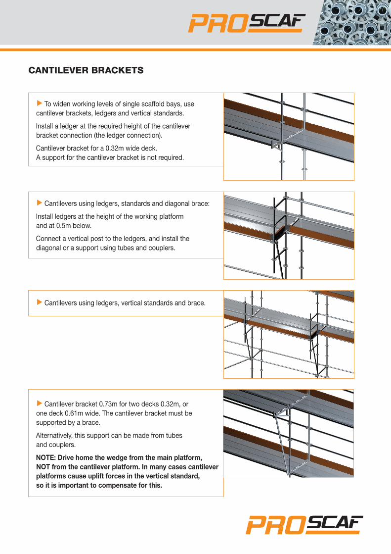
Cantilever bracket 0.73m for two decks 0.32m, or one deck 0.61m wide. The cantilever bracket must be supported by a brace.
Alternatively, this support can be made from tubes and couplers.
NOTE: Drive home the wedge from the main platform, NOT from the cantilever platform. In many cases cantilever platforms cause uplift forces in the vertical standard, so it is important to compensate for this.

www.proscaf.com
ASSEMBLY SECTION
sCaffold anChorage
Use wall ties and plastic inserts to anchor the scaffold to the wall. Wall ties must be connected by couplers to both vertical standards/ledgers.
The plastic inserts used depend on the wall structure and the anchor forces.
Alternatively, tie a ledger to an eyebolt. Place the wedge head centrally over the eyebolt (as with the connection to a rosette), and insert into the eye of the bolt.
NOTE: Check that the anchors’ load-bearing capacity will cope with the applied forces. Anchoring is one of the most important requirements for scaffold stability.
Tying the scaffold to horizontal elements (e.g. beams) can be achieved using tubes and couplers. If forces are transmitted in the longitudinal direction of the horizontal elements, the connection must be secured against movement in this direction.
Use tubes and couplers to tie scaffolding to vertical steel or concrete members.
NOTE: Check that the anchors’ load-bearing capacity will cope with the applied forces. Anchoring is one of the most important requirements for the scaffold’s stability.

sCaffold anChorage
An 8m anchor pattern staggered about 4m in height. External standards are tied every 4m. Internal standards must be anchored as shown in picture 1 every 8m, while the adjacent axis of the standards should be anchored staggered 4m in height.
Anchor pattern 4m in every axis of the standards. The scaffold is anchored every 4m in every axis of the standards.
Anchor pattern 2m in every axis of the standards.
With tarpaulin-clad scaffold, huge forces develop at the anchors and must be tied safely to the supporting structure.
Such forces can be reduced by a tight anchor pattern.
NOTE: Only tie scaffolding to walls or structures that have sufficient load-bearing capacity. Facade or similar scaffolds should be anchored by eye bolts and plastic inserts.
There are three anchor patterns: the one used depends on post spacing, the height of the scaffold and whether or not the scaffold will be clad by debris nets or tarpaulins.
Anchor forces should be calculated according to local codes or regulations and depend especially on the wind forces on the scaffold.

www.proscaf.com
ASSEMBLY SECTION
load Bearing CaPaCities of Main CoMPonents
Allowable loading of decks: Steel decks that connect with tubular ledgers
Bay length Duty Live Load
0.73 metre ≤ 6.6 kN / Bay (Heavy Duty)1.09 metre ≤ 6.6 kN / Bay (Heavy Duty)1.57 metre ≤ 6.6 kN / Bay (Heavy Duty)2.07 metre ≤ 6.6 kN / Bay (Heavy Duty)2.57 metre ≤ 6.6 kN / Bay (Heavy Duty)3.07 metre ≤ 6.6 kN / Bay (Heavy Duty)
DO NOT EXCEED THE LOADINGS SHOWN IN THE ABOVE TABLE
COMPLIES WITH AS/NZ51576.3 REQUIREMENTS FOR HEAVY DUTY LOAD
Allowable loading of decks: Steel decks that connect with U transoms
Bay length Duty Live Load
0.73 metre ≤ 6.6 kN / Bay (Heavy Duty)1.09 metre ≤ 6.6 kN / Bay (Heavy Duty)1.57 metre ≤ 6.6 kN / Bay (Heavy Duty)2.07 metre ≤ 6.6 kN / Bay (Heavy Duty)2.57 metre ≤ 6.6 kN / Bay (Heavy Duty)3.07 metre ≤ 6.6 kN / Bay (Heavy Duty)
DO NOT EXCEED THE LOADINGS SHOWN IN THE ABOVE TABLE
COMPLIES WITH AS/NZ51576.3 REQUIREMENTS FOR HEAVY DUTY LOAD
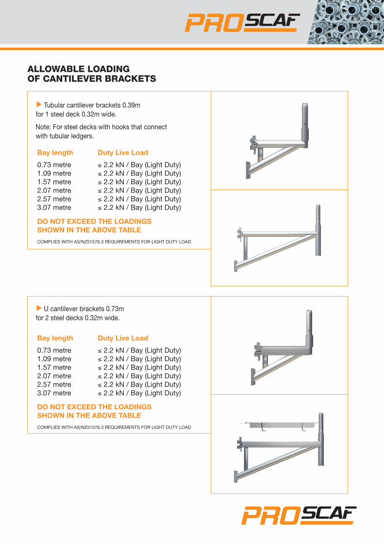
alloWaBle loading of Cantilever BraCkets
Tubular cantilever brackets 0.39m for 1 steel deck 0.32m wide.
Note: For steel decks with hooks that connect with tubular ledgers.
Bay length Duty Live Load
0.73 metre ≤ 2.2 kN / Bay (Light Duty)1.09 metre ≤ 2.2 kN / Bay (Light Duty)1.57 metre ≤ 2.2 kN / Bay (Light Duty)2.07 metre ≤ 2.2 kN / Bay (Light Duty)2.57 metre ≤ 2.2 kN / Bay (Light Duty)3.07 metre ≤ 2.2 kN / Bay (Light Duty)
DO NOT EXCEED THE LOADINGS SHOWN IN THE ABOVE TABLE
COMPLIES WITH AS/NZ51576.3 REQUIREMENTS FOR LIGHT DUTY LOAD
U cantilever brackets 0.73m for 2 steel decks 0.32m wide.
Bay length Duty Live Load
0.73 metre ≤ 2.2 kN / Bay (Light Duty)1.09 metre ≤ 2.2 kN / Bay (Light Duty)1.57 metre ≤ 2.2 kN / Bay (Light Duty)2.07 metre ≤ 2.2 kN / Bay (Light Duty)2.57 metre ≤ 2.2 kN / Bay (Light Duty)3.07 metre ≤ 2.2 kN / Bay (Light Duty)
DO NOT EXCEED THE LOADINGS SHOWN IN THE ABOVE TABLE
COMPLIES WITH AS/NZ51576.3 REQUIREMENTS FOR LIGHT DUTY LOAD

NZ freephone: 0800 776 722
AUS freephone: 1800 001 264
Email: [email protected]
PO Box 62, Maungaturoto
Northland, New Zealand
proscaf.com