Embed Size (px)
Citation preview
Assembly Language Programming
Atmel Microprocessors
using the
Linux Operating System
Peter D. Hiscocks
Syscomp Electronic Design Limited
Email: [email protected]
7 February 2017
1
Contents
1 Introduction 3
2 Why Atmel? 3
3 Why Assembly Language? 4
4 Development Process 4
5 Debugging 5
6 Alternative Development Environments 5
7 Organization of the Atmel Microprocessor 6
7.1 Program Memory (ROM) . . . . . . . . . . . . . . . . . . . . . . . . . . . . . . . . . . . . . . 6
7.2 Data Memory (RAM) . . . . . . . . . . . . . . . . . . . . . . . . . . . . . . . . . . . . . . . . 6
7.3 EEPROM . . . . . . . . . . . . . . . . . . . . . . . . . . . . . . . . . . . . . . . . . . . . . . 7
8 Assembly Language Directives 8
8.1 Segment Instructions . . . . . . . . . . . . . . . . . . . . . . . . . . . . . . . . . . . . . . . . 8
9 Assembly Language Instructions 9
9.1 Load Immediate . . . . . . . . . . . . . . . . . . . . . . . . . . . . . . . . . . . . . . . . . . . 9
9.2 Move (Copy Registers) . . . . . . . . . . . . . . . . . . . . . . . . . . . . . . . . . . . . . . . 9
9.3 Load or Store Direct, Register to SRAM . . . . . . . . . . . . . . . . . . . . . . . . . . . . . . 10
9.4 Load Indirect, with 16 bit Pointer . . . . . . . . . . . . . . . . . . . . . . . . . . . . . . . . . . 10
9.5 Load Indirect Indexed from RAM, with 16 bit Pointer . . . . . . . . . . . . . . . . . . . . . . . 10
9.6 Load Indirect from Program Memory: LPM . . . . . . . . . . . . . . . . . . . . . . . . . . . . 11
10 Assembly Language Instruction Restrictions 11
10.1 Instructions that Operate on Registers 0 to 31 . . . . . . . . . . . . . . . . . . . . . . . . . . . 11
10.2 Instructions that only operate on registers 16 to 31 . . . . . . . . . . . . . . . . . . . . . . . . . 12
10.3 Operating on IO Space . . . . . . . . . . . . . . . . . . . . . . . . . . . . . . . . . . . . . . . 12
10.4 Operating on SRAM Space . . . . . . . . . . . . . . . . . . . . . . . . . . . . . . . . . . . . . 12
10.5 Strategy for Register Useage . . . . . . . . . . . . . . . . . . . . . . . . . . . . . . . . . . . . 12
11 Examples 12
11.1 Turn on an LED . . . . . . . . . . . . . . . . . . . . . . . . . . . . . . . . . . . . . . . . . . . 12
11.2 Flash an LED . . . . . . . . . . . . . . . . . . . . . . . . . . . . . . . . . . . . . . . . . . . . 14
12 Serial Communication 14
13 Using Avrdude 18
14 Using the gavrasm Assembler 20
15 Installing and Using Cutecom 21
2
1 Introduction
In this note, we describe assembly language programming of Atmel microprocessors, using a host machine using
the Linux operating system.
There are many existing notes that describe programming Atmel microprocessors in the C language, on a
Linux machine. Here, we specifically address assembly language, for reasons explained below.
We assume the reader is familiar with the basic concepts of microprocessors, binary numbering, assembly
language and digital hardware.
2 Why Atmel?
There are many possible microprocessor families that one could use in this application. Here are some reasons
we focussed on the Atmel products.
• The Atmel parts have a huge range of memory sizes, speeds and periferal devices, so one or more processors
are likely to be useful for a project of this type.
• The parts are readily available at reasonable prices from distributors like Digikey and Mouser.
• Some of the lower-end devices are available in DIP (dual inline package), which means they can be plugged
into a protoboard for prototype development. The higher-end devices (ATXmega units) are sometimes
available on a ’breakout board’, which adapts a QFP (quad flat pack) package to a platform that can be
easily incorporated into a hardware prototype. See for example [21], [22], [23], [24], [25].
• There is a large ecosystem for these products from the manufacturer and from other users. One very
common example is the Arduino products, a computer board that uses Atmel microprocessors.
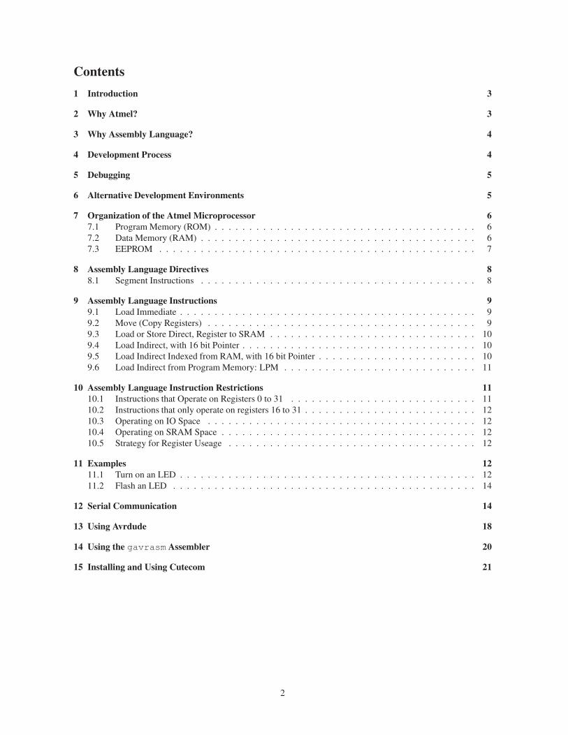
• The development tools are readily available at reasonable prices from this ecosystem. For example a USB
programmer dongle, the AVRISP II, is available from eBay for $39. There are many third party program-
mers and the required open source software for Linux is available.
• The architecture of Atmel microprocessors is relatively clean. For example, some microprocessors use
bank switching to select sections of working memory or sets of registers. This significantly complicates
programming and debugging.
Figure 1: Arduino Microprocessor Board with Atmel AVRISP II Programmer. Arduino board is powered by
external +12VDC adaptor. Programmer connects to Linux host via USB cable.
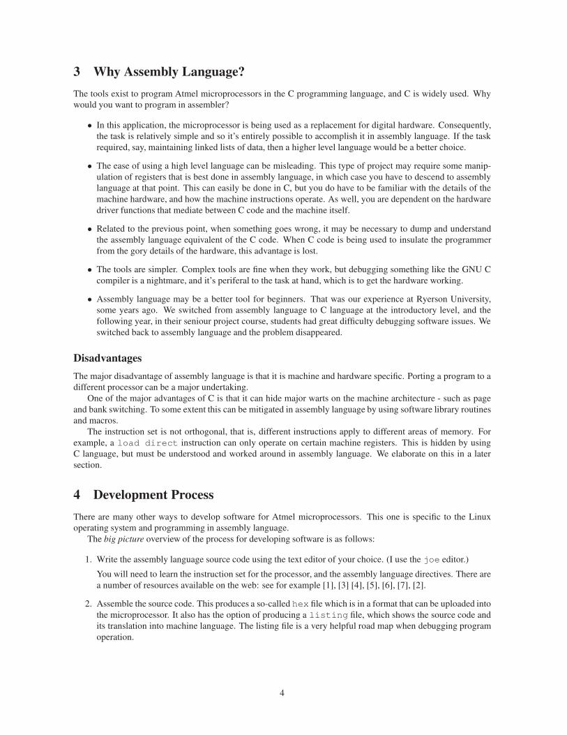
3 Why Assembly Language?
The tools exist to program Atmel microprocessors in the C programming language, and C is widely used. Why
would you want to program in assembler?
• In this application, the microprocessor is being used as a replacement for digital hardware. Consequently,
the task is relatively simple and so it’s entirely possible to accomplish it in assembly language. If the task
required, say, maintaining linked lists of data, then a higher level language would be a better choice.
• The ease of using a high level language can be misleading. This type of project may require some manip-
ulation of registers that is best done in assembly language, in which case you have to descend to assembly
language at that point. This can easily be done in C, but you do have to be familiar with the details of the
machine hardware, and how the machine instructions operate. As well, you are dependent on the hardware
driver functions that mediate between C code and the machine itself.
• Related to the previous point, when something goes wrong, it may be necessary to dump and understand
the assembly language equivalent of the C code. When C code is being used to insulate the programmer
from the gory details of the hardware, this advantage is lost.
• The tools are simpler. Complex tools are fine when they work, but debugging something like the GNU C
compiler is a nightmare, and it’s periferal to the task at hand, which is to get the hardware working.
• Assembly language may be a better tool for beginners. That was our experience at Ryerson University,
some years ago. We switched from assembly language to C language at the introductory level, and the
following year, in their seniour project course, students had great difficulty debugging software issues. We
switched back to assembly language and the problem disappeared.
Disadvantages
The major disadvantage of assembly language is that it is machine and hardware specific. Porting a program to a
different processor can be a major undertaking.
One of the major advantages of C is that it can hide major warts on the machine architecture - such as page
and bank switching. To some extent this can be mitigated in assembly language by using software library routines
and macros.
The instruction set is not orthogonal, that is, different instructions apply to different areas of memory. For
example, a load direct instruction can only operate on certain machine registers. This is hidden by using
C language, but must be understood and worked around in assembly language. We elaborate on this in a later
section.
4 Development Process
There are many other ways to develop software for Atmel microprocessors. This one is specific to the Linux
operating system and programming in assembly language.
The big picture overview of the process for developing software is as follows:
1. Write the assembly language source code using the text editor of your choice. (I use the joe editor.)
You will need to learn the instruction set for the processor, and the assembly language directives. There are
a number of resources available on the web: see for example [1], [3] [4], [5], [6], [7], [2].
2. Assemble the source code. This produces a so-called hex file which is in a format that can be uploaded into
the microprocessor. It also has the option of producing a listing file, which shows the source code and
its translation into machine language. The listing file is a very helpful road map when debugging program
operation.
4
There are two assemblers that will work under Linux: avra [10] and gavrasm [9]. The avra assembler
supports the smaller processors that are available in DIP packages and therefore of greatest interest to hob-
byists. It does not support the XMega versions. Run the command avra --devices to see a complete
list of the supported devices.
The gavrasm assembler does support the XMega versions of processors. The XMega devices run at a faster
clock rate, have more memory, and the A/D converter is faster (200kS/sec vs 2MS/sec) and higher resolution
(10 vs 12 bits. The hobbyist may not be able to solder the 100 pin surface mount package, but it is available
from various vendors as a printed-circuit module. Run the command gavrasm -T to see a complete list
of devices.
The avra assembler (and the official Atmel assembler, that only runs under Windows) both require a
definition file that specifies all the processor memory symbolic names and address locations.
The gavrasm assembler has that built-in, so a part definition file is not required. The assembler uses the
.include statement to identify the appropriate microprocessor definitions.
3. Plug in a programming dongle such as the AVRISP II so that it connects a USB port on the Linux
computer host to the the target microprocessor system.
4. Upload the hex file into the microprocessor using the avrdude programming software.
5. Reset the microprocessor and the code should run.
5 Debugging
The program doesn’t work as expected. Now what?
There are various possible debugging tools, all with various advantages and disadvantages. One of the simplest
and most useful is a debugging monitor program. This is a small section of code that provides utility
routines to help in the debugging process. For example, it’s useful to be able to dump memory registors to the
host PC so they can be displayed and diagnosed. On an Atmel processor, the stack pointer, stack, status register
and other machine registers are memory mapped into the random-access memory file so they are easily accessible.
The disadvantage of a monitor is that it requires some machine resources. It occupies some program memory,
and requires the use of the serial port to send information to the host PC. As it turns out, the monitor program is
very small, and the serial port can be shared with the program being debugged, so these are not serious limitations.
The monitor program can be installed in a protected area of memory, or it can simply be included with the
program being debugged.
Breakpoints are invaluable in debugging the flow of a program. Did the execution get to a particular point in
the code? Were the registers what was expected at that point?
In this case, the breakpoint is an instruction to jump to the monitor program, inserted in the source code at
the desired location. This requires re-assembling and downloading the program with each breakpoint setting – a
minor nuisance but relatively quick with a modern PC as host machine. We use the keymon monitor program
because it is simple and well documented.
6 Alternative Development Environments
Atmel provide the excellent Studio development environment for free. Unfortunately, it runs only under the
Windows operating system. According to recent indications it does not run properly under WINE, the Windows
environment for Linux. However, an older version may install and run properly under Wine [17].
It is also possible to set up the GCC tool chain to generate machine code for Atmel processors [18]. Then
GDB may be used as a debugger. For someone who prefers to code in the C language and is familiar with the
GCC tool chain, this may be attractive.
5
7 Organization of the Atmel Microprocessor
A good place to begin understanding of a computer architecture is the memory map: how the memory is organized,
and where various features are located. For example, all processors have a stack memory for the support of
subroutines – and other functions. Where is it located on this machine, and how does it function.
Atmel microprocessors are a Harvard Architecture, that is, the code runs in a separate section of memory from
the read-write memory.
We use the Atmel ATmega168 as an example. (The Atmel ATmega168 is used in the Arduino Diecimila,
pictured in figure 1.)
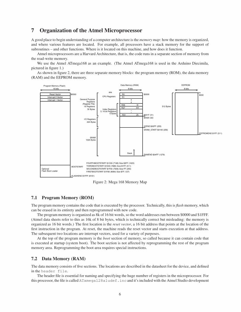
As shown in figure 2, there are three separate memory blocks: the program memory (ROM), the data memory
(RAM) and the EEPROM memory.
✛ ✲ ✛ ✲✛ ✲
............
8 bits 8 bits
$0000Reset Vector
Interrupt 0 Vector
Interrupt 1 Vector
OptionalFlash Boot Loader
16 bits
Program Memory (Flash)
FOURTHBOOTSTART $1C00 (7168) Size $3FF (1023)
SECONDBOOTSTART $1F00 (7936) Size FF (255)
FIRSTBOOTSTART $1F80 (8064) Size $7F (127)
THIRDBOOTSTART $1E00 (7680) Size $1FF (511)
FLASHEND $1FFF (8191)
BOOTSTART
Data Memory (RAM)
I/O Registers
SRAM1024 Bytes
IOEND $00FF (255)
SRAM_START $0100 (256)
RAMEND $04FF (1279)
$0000
224 Bytes
General PurposeRegisters
(Register File)
16 Registers
32 Bytes
EEPROM
EEPROMEND $1FF (511)
$000
512 Bytes
Stack
$0020 (32)
$001F (31)
Index Registers3, 16 bit Registers
6 Bytes
CPU Registers
aka
Xl
XH
Zh
R0
R1
R26
R27
R31
Figure 2: Mega 168 Memory Map
7.1 Program Memory (ROM)
The program memory contains the code that is executed by the processor. Technically, this is flash memory, which
can be erased in its entirety and then reprogrammed with new code.
The program memory is organized as 8k of 16 bit words, so the word addresses run between $0000 and $1FFF.
(Atmel data sheets refer to this as 16k of 8 bit bytes, which is technically correct but misleading: the memory is
organized as 16 bit words.) The first location is the reset vector, a 16 bit address that points at the location of the
first instruction in the program. At reset, the machine reads the reset vector and starts execution at that address.
The subsequent two locations are interrupt vectors, used for a variety of purposes.
At the top of the program memory is the boot section of memory, so called because it can contain code that
is executed at startup (system boot). The boot section is not affected by reprogramming the rest of the program
memory area. Reprogramming the boot area requires special instructions.
7.2 Data Memory (RAM)
The data memory consists of five sections. The locations are described in the datasheet for the device, and defined
in the header file.
The header file is essential for naming and specifying the huge number of registers in the microprocessor. For
this processor, the file is called ATxmega128a1udef.inc and it’s included with the Atmel Studio development
6
software.
This file should be included (using a .include directive) at the beginning of an assembly language program.
Then the symbolic names of the registers can be used in the assembly language code and their actual location in
memory is automatically taken care of when the program is assembled.
Register File, 0 - 31 This area is organized as 32, 8 bit registers, known as R0 to R31. (Assemblers for the Atmel
microprocessors recognize the names R0 through R31, and so their locations do not need to be defined in a
header file or elsewhere.)
The six registers R26 through R31 are also available for use as 16 bit index registers in load and store
operations.
Hidden in the fine print of the instructions is the following:
LDI: Loads an 8 bit constant directly to register 16 to 31.
In other words, the load immediate instruction does not work on all registers. Registers R0 to R15 have
some restrictions. Use those registers with caution, or use registers R16 through R311.
Many example snippets of code show R16 being used for temporary storage, so that register (and subsequent
registers up to R31) are a safe choice.
IO Registers, 32-95 These registers are the memory-mapped locations of various periferal devices. Here’s an
example.
.equ VPORT3_DIR = 28 // I/O Port Data Direction
.equ VPORT3_OUT = 29 // I/O Port Output
.equ VPORT3_IN = 30 // I/O Port Input
.equ VPORT3_INTFLAGS = 31 // Interrupt Flag Register
.equ CPU_SPL = 61 // Stack Pointer Low
.equ CPU_SPH = 62 // Stack Pointer High
.equ CPU_SREG = 63 // Status Register
Extended IO Registers, 96-256 More memory mapped periferal control registers. This section requires a differ-
ent addressing mode to the IO Register section.
Stack The stack starts at the location defined by the stack pointer, locations 61 and 62 (see above). It can be
placed anywhere in RAM, but is usually placed at the very end of memory - in this case, location 1279. The
stack grows downward, that is, to lower numbered addresses.
Notice that the only thing automatically saved on the stack during a subroutine call or interrupt is the
program counter. It’s good practice to save the processor status register. An errant program can overwrite
sections of the stack, which will cause the program to crash.
RAM Storage, 256-1279 Between the end of the extended IO registers and the stack is available RAM for tem-
porary storage. The contents of RAM are lost when the power is removed.
7.3 EEPROM
The Electrically Eraseable, Programmable Read Only Memory consists of 512 bytes of memory that can be
individually erased and programmed. It’s not as simple as writing to the memory location: a software routine
must be used to write to and read from EEPROM. (The code is given in the datasheet.)
EEPROM retains its contents when the power is removed, so it’s useful for storing things like calibration
constants or the configuration of the machine.
1This means that the Atmel instruction set is unfortunately not regular, in that certain instructions will not work on certain registers.
7
8 Assembly Language Directives
8.1 Segment Instructions
As shown in the memory map of figure 2, there are three memory spaces in this Harvard architecture machine:
code, data and eeprom, corresponding respectively to Flash memory, RAM and EEPROM.
The directives to specify these sections of memory are .CSEG (code segment), .DSEG (data segment) and
.ESEG.
The assembler is notified of the destination for the code using one of these directives. If not specified, it’s
assumed to be the code segment. It is not essential, but good practice to define the segment regardless.
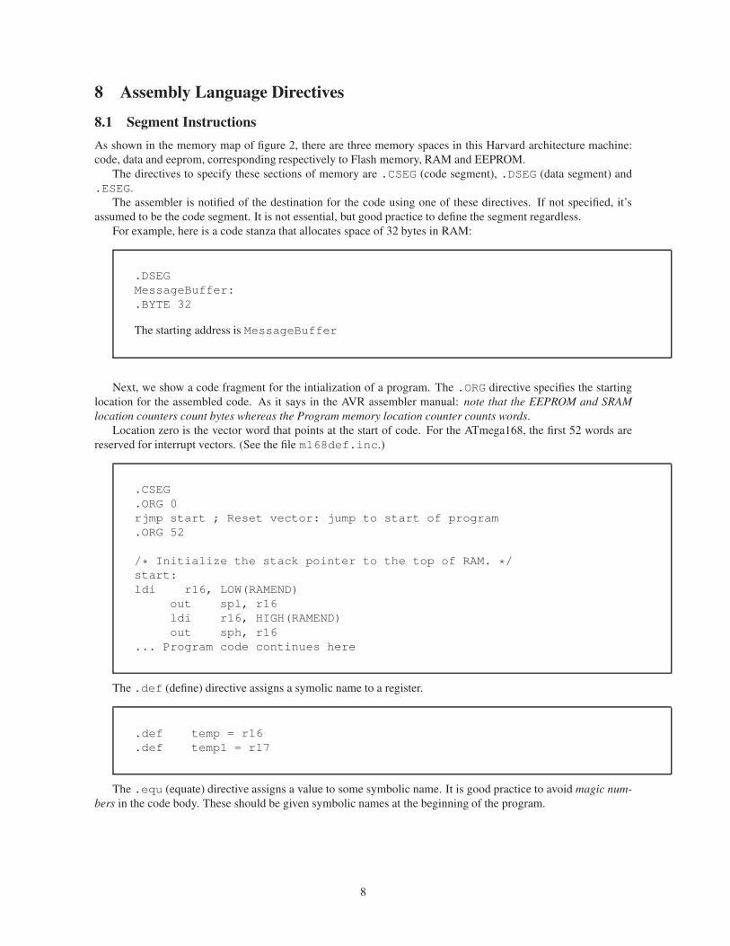
For example, here is a code stanza that allocates space of 32 bytes in RAM:
.DSEG
MessageBuffer:
.BYTE 32
The starting address is MessageBuffer
Next, we show a code fragment for the intialization of a program. The .ORG directive specifies the starting
location for the assembled code. As it says in the AVR assembler manual: note that the EEPROM and SRAM
location counters count bytes whereas the Program memory location counter counts words.
Location zero is the vector word that points at the start of code. For the ATmega168, the first 52 words are
reserved for interrupt vectors. (See the file m168def.inc.)
.CSEG
.ORG 0
rjmp start ; Reset vector: jump to start of program
.ORG 52
/* Initialize the stack pointer to the top of RAM. */
start:
ldi r16, LOW(RAMEND)
out spl, r16
ldi r16, HIGH(RAMEND)
out sph, r16
... Program code continues here
The .def (define) directive assigns a symolic name to a register.
.def temp = r16
.def temp1 = r17
The .equ (equate) directive assigns a value to some symbolic name. It is good practice to avoid magic num-
bers in the code body. These should be given symbolic names at the beginning of the program.
8
.equ MinIntDly = 1000 ; Minimum integration delay, 20mSec
.equ MaxIntDly = 10000; Maximum integration delay, 200mSec
9 Assembly Language Instructions
9.1 Load Immediate
.DEF myregister R16
LDI myregister, 150
This instruction loads a register with a specified value. Registers must be R0 to R31. Notice that we define
register R16 with our own name, myregister. This is best practice, since it helps document the objective of
the code.
The instruction given above loads myregister with the value 150.
(In some other machine instruction sets, this is accomplished by a load accumulator immediate
mode, save accumulator to memory location sequence. In this machine, the register file functions
as multiple accumulator registers.)
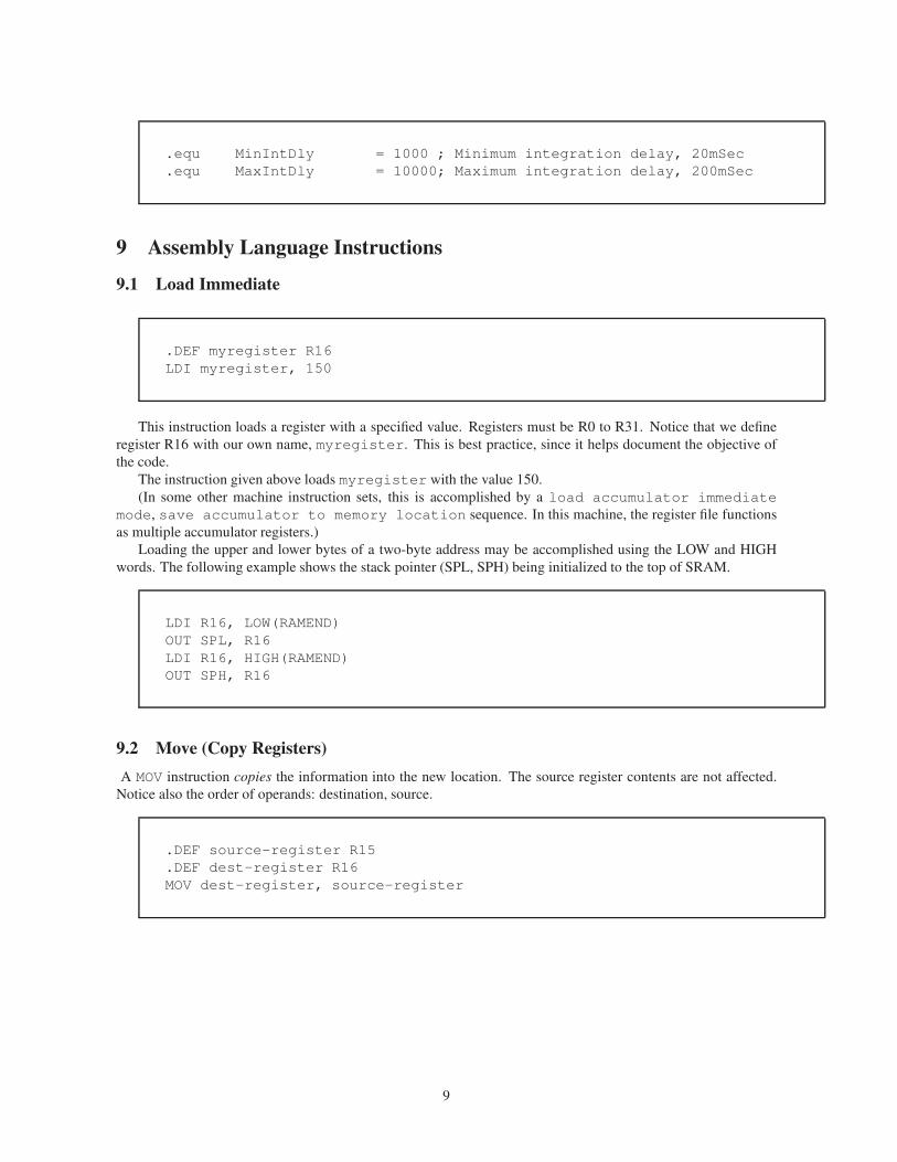
Loading the upper and lower bytes of a two-byte address may be accomplished using the LOW and HIGH
words. The following example shows the stack pointer (SPL, SPH) being initialized to the top of SRAM.
LDI R16, LOW(RAMEND)
OUT SPL, R16
LDI R16, HIGH(RAMEND)
OUT SPH, R16
9.2 Move (Copy Registers)
A MOV instruction copies the information into the new location. The source register contents are not affected.
Notice also the order of operands: destination, source.
.DEF source-register R15
.DEF dest-register R16
MOV dest-register, source-register
9
9.3 Load or Store Direct, Register to SRAM
LDS R1, 0x0060 ; load register R1 from RAM location 0x0060
STS 0x0060, R1 ; store the contents of register R1 in RAM location 0x0060
The assembler automatically changes the instruction format to cope with an 8 bit or 16 bit RAM address.
9.4 Load Indirect, with 16 bit Pointer
Consider that you have a series of values stored in an array in RAM. We’ll assume that 3 bytes are allocated to
each data entry. We wish to retrieve array entry number 11. Then the address in memory of that information is at
location = base-address + 3× index
where location is the starting address in RAM of the data we are after, base-address is the starting address
of the array storage, and index is the index into the array (11 in this case).
Suppose that the base address is location 1000. Then the starting address of the data to be retrieved is at 1033.
This address is straightforward to calculate using processor instructions. Now we need a method of retrieving
data from that location: indirect addressing.
The X, Y and Z registers can be used to perform this pointer or indirect addressing. Here’s the sequence of
instructions.
LDI XH, HIGH(1033)
LDI XL, LOW(1033)
LD R1,X
The first instruction extracts the upper 8 bits of the address into the upper byte of the X index register. The
second instruction extracts the lower 8 bits of the address into the lower byte of the X index register. Now the X
index register is pointing at location 1033 and executing the third instruction will transfer that information into
register R1.
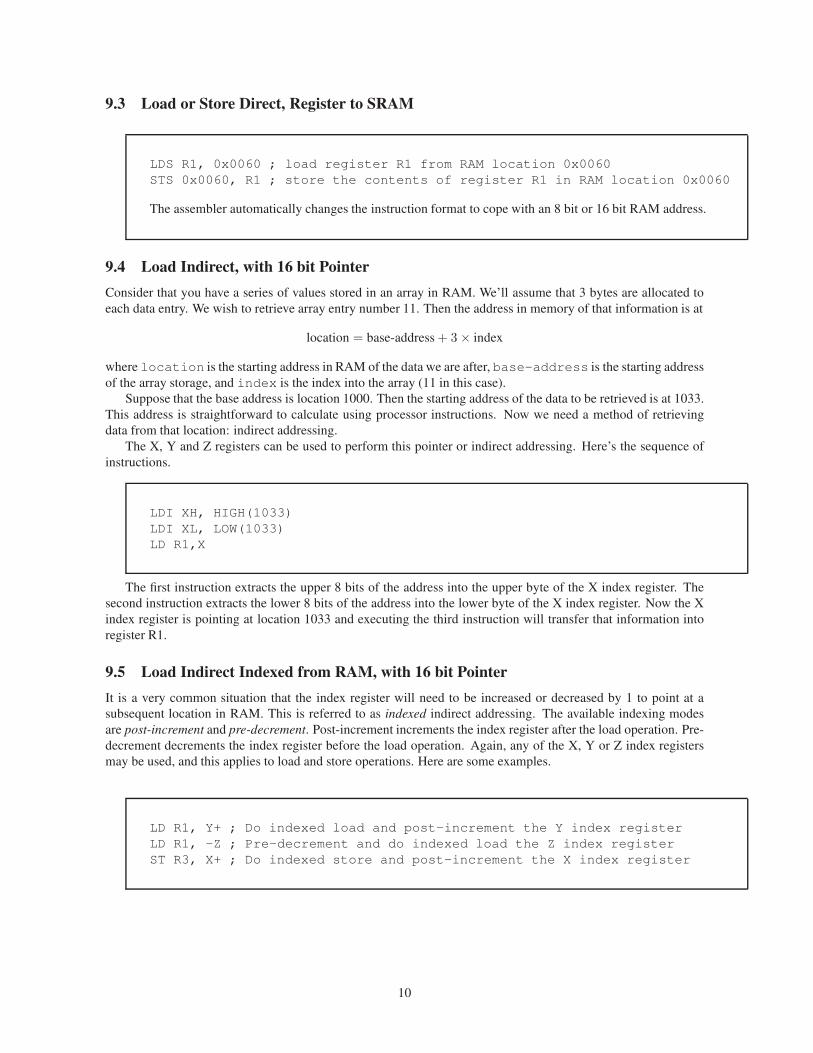
9.5 Load Indirect Indexed from RAM, with 16 bit Pointer
It is a very common situation that the index register will need to be increased or decreased by 1 to point at a
subsequent location in RAM. This is referred to as indexed indirect addressing. The available indexing modes
are post-increment and pre-decrement. Post-increment increments the index register after the load operation. Pre-
decrement decrements the index register before the load operation. Again, any of the X, Y or Z index registers
may be used, and this applies to load and store operations. Here are some examples.
LD R1, Y+ ; Do indexed load and post-increment the Y index register
LD R1, -Z ; Pre-decrement and do indexed load the Z index register
ST R3, X+ ; Do indexed store and post-increment the X index register
10
9.6 Load Indirect from Program Memory: LPM
A very common requirement of a program: a message string is to be sent to a host computer over the serial
port, or to a display interfaced to the Atmel microprocessor. The message string will be written into the program
flash memory using the .DB directive. Then the processor will read that message string and transmit or display it.
The load and store instructions discussed previously all operate on register locations in Data memory (RAM).
Consequently, another instruction is required to load data from the program memory. (This is a direct consequence
of the Harvard architecture: a von-Neumann architecture would not have this issue.) That is the purpose of the
LPM, instruction: Load Program Memory.
The use of LPM is described with an example in Atmel application note AVR108, [8]. The key points are
illustrated in the code fragment below:
ldi ZH,high(2*message) ; Load high part of byte address into ZH
ldi ZL,low(2*message) ; Load low part of byte address into ZL
loadbyte:
lpm ; Load byte from program memory into r0
...load loop continues here
adiw ZL,1 ; Increase Z registers
rjmp loadbyte ; Loop until done
message:
.db
"Hello World"
.db 0
TheZ index register is 16 bits, consisting of the low byteZL and the high byte ZH. The labelmessage
specifies a location in code memory, so it is a word address. Consequently, to obtain the byte address for the Z
register, the value must be multiplied by 2. Then the high and low bytes must be extracted using the HIGH and
LOW directives.
The adiw instruction then increments the Z register each time a character is selected from the list. A zero
byte terminates the loop. The increment in this case is 1, but can range 0 to 63.
10 Assembly Language Instruction Restrictions
From the point of view of one writing a program in assembly language, the Atmel processors have a number of
arbitrary restrictions on the instructions. These restrictions are hidden from view when using a C compiler, but
unfortunately not for assembly language.
In the official description of instructions, the restriction is stated in a form like this:
ANDI Rd,K 16<=d<=31, 0 < K < 255
Interpreted, this means that the ANDI instruction can operate on registers between 16 and 31 inclusive. The
operand can range over 0 to 255 (8 bits).
10.1 Instructions that Operate on Registers 0 to 31
All arithmetic and logic instructions that do not use an immediate operand can operate on these registers. The
MOV instruction is used to copy the contents of one register to another.
11
10.2 Instructions that only operate on registers 16 to 31
All instructions that have an immediate operand (constant K) can only operate on these registers.
For example, the LDI instruction , Load Immediate, can load a value of 0 to 255 into any of registers 16 to 31
(inclusive).
10.3 Operating on IO Space
The IN instruction can be used to reference what is the Input-Output space on some devices. In practice, the reach
of this instruction is from registers 0 to 63. The input-output space extends far beyond that on XMega processors.
This is useful when pushing the status register location 63 onto the stack. The ’push’ instruction can only
work on register locations 0 to 31.
in temp,CPU_SREG ; Get the status register
push temp
10.4 Operating on SRAM Space
The LD, LDS, ST and STS instructions and their variants can address any 16 bit location from 0 to 65535.
In the code example for Serial Communication, you can see the LDS and STS instructions being used
to address registers that are nominally in IO space but actually in the range of larger addresses. For example,
USARTC0_STATUS is at location 2209 in the memory map.
10.5 Strategy for Register Useage
Registers 16 to 31 can be used as general purpose registers since all register instructions can operate on 0 to 31
and immediate instructions can operate 16 to 31.
Registers R26 to R31 can be treated as 16 bit registers, so they should be reserved for that purpose. They are
also used as pointer registers for indirect addressing.
This leaves the 10 registers R16 to R25 that can be used for general purposes.
11 Examples
11.1 Turn on an LED
Here we assume an Arduino Diecimila board with Atmel ATmega168 processor, schematic as shown in figure 3.
The board conveniently has an LED connected between the digital output PB5 and ground. This first program
will simply turn on that LED. (The output from the microprocessor also functions as the SCK signal for serial
programming. That shouldn’t be an issue if the programmer is disconnected before running the program.)
We will use the gavrasm assembler. Notice that, unlike other assemblers, there is no need to include a header
12
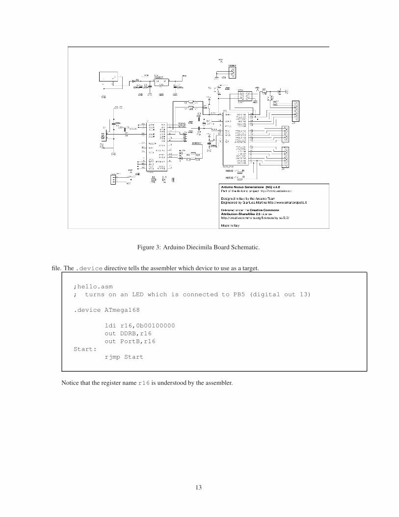
Figure 3: Arduino Diecimila Board Schematic.
file. The .device directive tells the assembler which device to use as a target.
;hello.asm
; turns on an LED which is connected to PB5 (digital out 13)
.device ATmega168
ldi r16,0b00100000
out DDRB,r16
out PortB,r16
Start:
rjmp Start
Notice that the register name r16 is understood by the assembler.
13
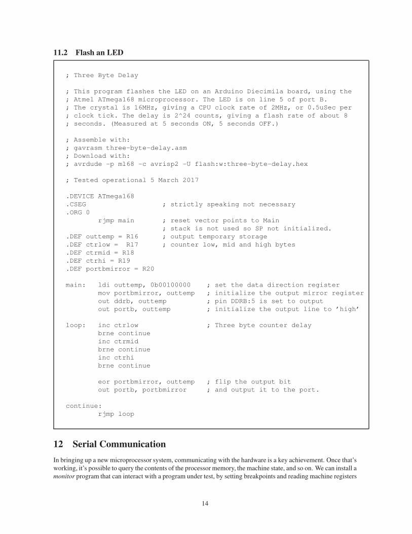
11.2 Flash an LED
; Three Byte Delay
; This program flashes the LED on an Arduino Diecimila board, using the
; Atmel ATmega168 microprocessor. The LED is on line 5 of port B.
; The crystal is 16MHz, giving a CPU clock rate of 2MHz, or 0.5uSec per
; clock tick. The delay is 2^24 counts, giving a flash rate of about 8
; seconds. (Measured at 5 seconds ON, 5 seconds OFF.)
; Assemble with:
; gavrasm three-byte-delay.asm
; Download with:
; avrdude -p m168 -c avrisp2 -U flash:w:three-byte-delay.hex
; Tested operational 5 March 2017
.DEVICE ATmega168
.CSEG ; strictly speaking not necessary
.ORG 0
rjmp main ; reset vector points to Main
; stack is not used so SP not initialized.
.DEF outtemp = R16 ; output temporary storage
.DEF ctrlow = R17 ; counter low, mid and high bytes
.DEF ctrmid = R18
.DEF ctrhi = R19
.DEF portbmirror = R20
main: ldi outtemp, 0b00100000 ; set the data direction register
mov portbmirror, outtemp ; initialize the output mirror register
out ddrb, outtemp ; pin DDRB:5 is set to output
out portb, outtemp ; initialize the output line to ’high’
loop: inc ctrlow ; Three byte counter delay
brne continue
inc ctrmid
brne continue
inc ctrhi
brne continue
eor portbmirror, outtemp ; flip the output bit
out portb, portbmirror ; and output it to the port.
continue:
rjmp loop
12 Serial Communication
In bringing up a new microprocessor system, communicating with the hardware is a key achievement. Once that’s
working, it’s possible to query the contents of the processor memory, the machine state, and so on. We can install a
monitor program that can interact with a program under test, by setting breakpoints and reading machine registers
14

at the breakpoint.
A useful first step is a program that will cause the microprocessor to repeatedly send some ASCII character.
That ensures that the serial port is configured correctly and that the terminal on the host is talking properly to the
assigned serial port. This can be tough: if it doesn’t work, there are few options for diagnosing the problems. It
has to be mostly trial and error.
There are a number of references that describe how to program the serial port of an Arduino microprocessor:
[26], [27], [28] [29], [30]. Many of these show C code, but converting the information to assembly language is
straightforward.
Some points that were uncovered in the course of getting this to work:
• In the Atmel ATmega168 datasheet [19], the code shows IN and OUT instructions being used to access
the SCI (serial communications interface, aka UART, universal asynchronous receiver transmitter). On the
ATmega168 the registers are in the extended IO address space, so IN and OUT instructions won’t work.
(The assembler has your back on this: it generates an error message.) You must use the LDS and STS
instructions, which can address the full IO address space.
• There is no mention of setting the output port line for the serial transmitter, Tx. It may not be essential, but
it seems prudent to set the data direction register PD1, to an output.
• On the Arduino Diecimila circuit board, there are two LEDs labelled Rx and Tx. One might logically
expect those LEDs would operate when the serial port is receiving or sending information. However, if you
look at the schematic of the Diecimila, as shown in figure 3, the LEDs are driven by the FTDI interface
chip, which connects the serial output of the processor to the USB connection of the host. We were fooled
by the lack of activity on the Tx led when the program was operating to believe there was a problem with
the code. Eventually we hooked up an oscilloscope to the Tx pin PD1 and saw that there was activity, so
the code was probably working correctly. (As it turned out, that was the case.)
• The Tx led does flash when serial communication is established via the USB interface.
• The original terminal emulator program running on the Linux host was gtkterm. For reasons unknown,
that program did not display the incoming characters. We installed the cutecom terminal emulator and
that worked correctly.
• Given the unknowns of the USB connection, it wasn’t clear what should be the baud rate on the micropro-
cessor or the terminal emulator. As it turned out, 9600 baud and 8N1 (8 start bits, no parity, one stop bit)
worked properly.
Section 15 on page 21 describes in detail how to install and use the cutecom terminal emulator.
15
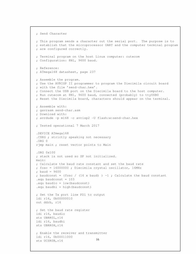
; Send Character
; This program sends a character out the serial port. The purpose is to
; establish that the microprocessor UART and the computer terminal program
; are configured correctly.
; Terminal program on the host Linux computer: cutecom
; Configuration: 8N1, 9600 baud.
; Reference:
; ATmega168 datasheet, page 237
; Assemble the program.
; Use the AVRISP II programmer to program the Diecimila circuit board
; with the file ’send-char.hex’.
; Connect the USB port on the Diecimila board to the host computer.
; Run cutecom at 8N1, 9600 baud, connected (probably) to ttyUSB0
; Reset the Diecimila board, characters should appear on the terminal.
; Assemble with:
; gavrasm send-char.asm
; Download with:
; avrdude -p m168 -c avrisp2 -U flash:w:send-char.hex
; Tested operational 7 March 2017
.DEVICE ATmega168
.CSEG ; strictly speaking not necessary
.ORG 0
rjmp main ; reset vector points to Main
.ORG 0x100
; stack is not used so SP not initialized.
main:
; Calculate the baud rate constant and set the baud rate
; fosc = 16000000 ; Diecimila crystal oscillator, 16MHz
; baud = 9600
; baudconst = (fosc / (16 x baud) ) -1 ; Calculate the baud constant
.equ baudconst = 103
.equ baudlo = low(baudconst)
.equ baudhi = high(baudconst)
; Set the Tx port line PD1 to output
ldi r16, 0b00000010
out ddrb, r16
; Set the baud rate register
ldi r16, baudlo
sts UBRR0L,r16
ldi r16, baudhi
sts UBRR0H,r16
; Enable the receiver and transmitter
ldi r16, 0b00011000
sts UCSR0B,r16 16
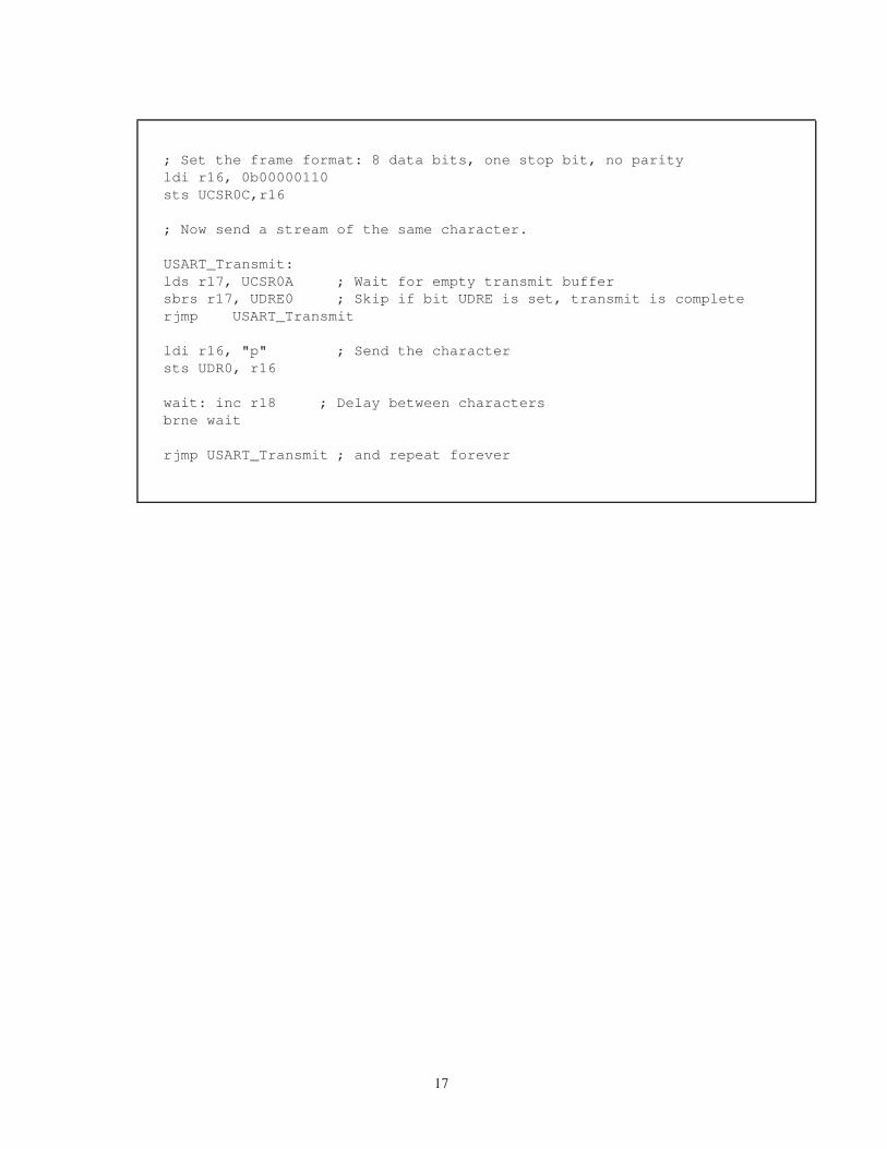
; Set the frame format: 8 data bits, one stop bit, no parity
ldi r16, 0b00000110
sts UCSR0C,r16
; Now send a stream of the same character.
USART_Transmit:
lds r17, UCSR0A ; Wait for empty transmit buffer
sbrs r17, UDRE0 ; Skip if bit UDRE is set, transmit is complete
rjmp USART_Transmit
ldi r16, "p" ; Send the character
sts UDR0, r16
wait: inc r18 ; Delay between characters
brne wait
rjmp USART_Transmit ; and repeat forever
17
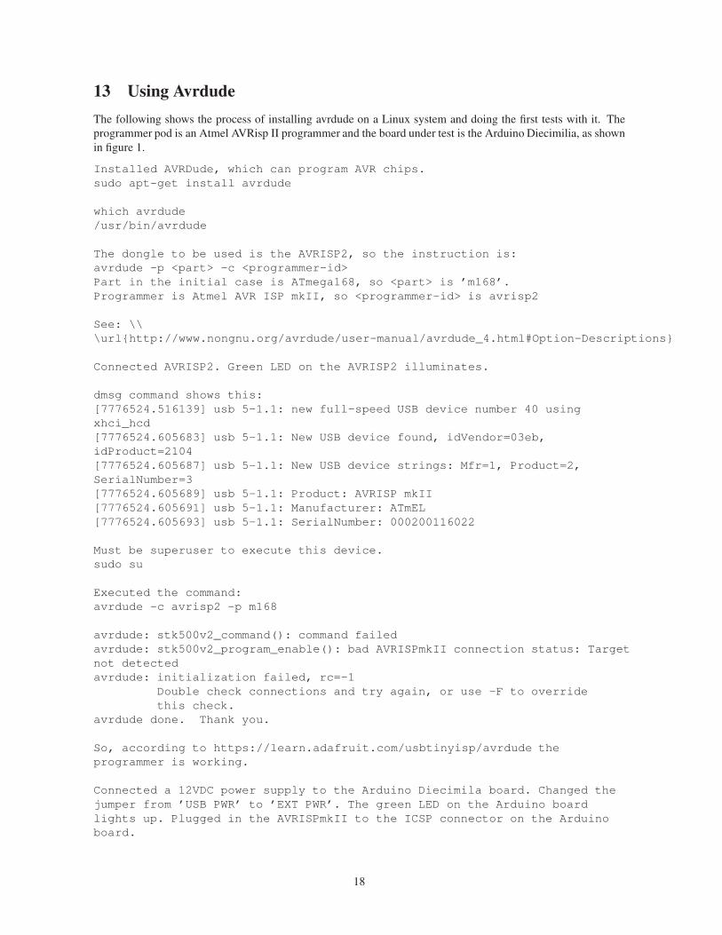
13 Using Avrdude
The following shows the process of installing avrdude on a Linux system and doing the first tests with it. The
programmer pod is an Atmel AVRisp II programmer and the board under test is the Arduino Diecimilia, as shown
in figure 1.
Installed AVRDude, which can program AVR chips.
sudo apt-get install avrdude
which avrdude
/usr/bin/avrdude
The dongle to be used is the AVRISP2, so the instruction is:
avrdude -p <part> -c <programmer-id>
Part in the initial case is ATmega168, so <part> is ’m168’.
Programmer is Atmel AVR ISP mkII, so <programmer-id> is avrisp2
See: \\
\url{http://www.nongnu.org/avrdude/user-manual/avrdude_4.html#Option-Descriptions}
Connected AVRISP2. Green LED on the AVRISP2 illuminates.
dmsg command shows this:
[7776524.516139] usb 5-1.1: new full-speed USB device number 40 using
xhci_hcd
[7776524.605683] usb 5-1.1: New USB device found, idVendor=03eb,
idProduct=2104
[7776524.605687] usb 5-1.1: New USB device strings: Mfr=1, Product=2,
SerialNumber=3
[7776524.605689] usb 5-1.1: Product: AVRISP mkII
[7776524.605691] usb 5-1.1: Manufacturer: ATmEL
[7776524.605693] usb 5-1.1: SerialNumber: 000200116022
Must be superuser to execute this device.
sudo su
Executed the command:
avrdude -c avrisp2 -p m168
avrdude: stk500v2_command(): command failed
avrdude: stk500v2_program_enable(): bad AVRISPmkII connection status: Target
not detected
avrdude: initialization failed, rc=-1
Double check connections and try again, or use -F to override
this check.
avrdude done. Thank you.
So, according to https://learn.adafruit.com/usbtinyisp/avrdude the
programmer is working.
Connected a 12VDC power supply to the Arduino Diecimila board. Changed the
jumper from ’USB PWR’ to ’EXT PWR’. The green LED on the Arduino board
lights up. Plugged in the AVRISPmkII to the ICSP connector on the Arduino
board.
18
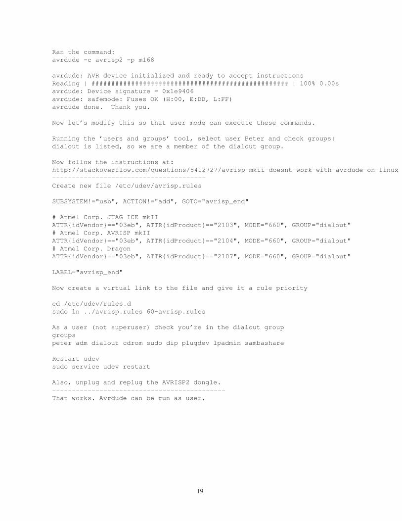
Ran the command:
avrdude -c avrisp2 -p m168
avrdude: AVR device initialized and ready to accept instructions
Reading | ################################################## | 100% 0.00s
avrdude: Device signature = 0x1e9406
avrdude: safemode: Fuses OK (H:00, E:DD, L:FF)
avrdude done. Thank you.
Now let’s modify this so that user mode can execute these commands.
Running the ’users and groups’ tool, select user Peter and check groups:
dialout is listed, so we are a member of the dialout group.
Now follow the instructions at:
http://stackoverflow.com/questions/5412727/avrisp-mkii-doesnt-work-with-avrdude-on-linux
---------------------------------------
Create new file /etc/udev/avrisp.rules
SUBSYSTEM!="usb", ACTION!="add", GOTO="avrisp_end"
# Atmel Corp. JTAG ICE mkII
ATTR{idVendor}=="03eb", ATTR{idProduct}=="2103", MODE="660", GROUP="dialout"
# Atmel Corp. AVRISP mkII
ATTR{idVendor}=="03eb", ATTR{idProduct}=="2104", MODE="660", GROUP="dialout"
# Atmel Corp. Dragon
ATTR{idVendor}=="03eb", ATTR{idProduct}=="2107", MODE="660", GROUP="dialout"
LABEL="avrisp_end"
Now create a virtual link to the file and give it a rule priority
cd /etc/udev/rules.d
sudo ln ../avrisp.rules 60-avrisp.rules
As a user (not superuser) check you’re in the dialout group
groups
peter adm dialout cdrom sudo dip plugdev lpadmin sambashare
Restart udev
sudo service udev restart
Also, unplug and replug the AVRISP2 dongle.
--------------------------------------------
That works. Avrdude can be run as user.
19
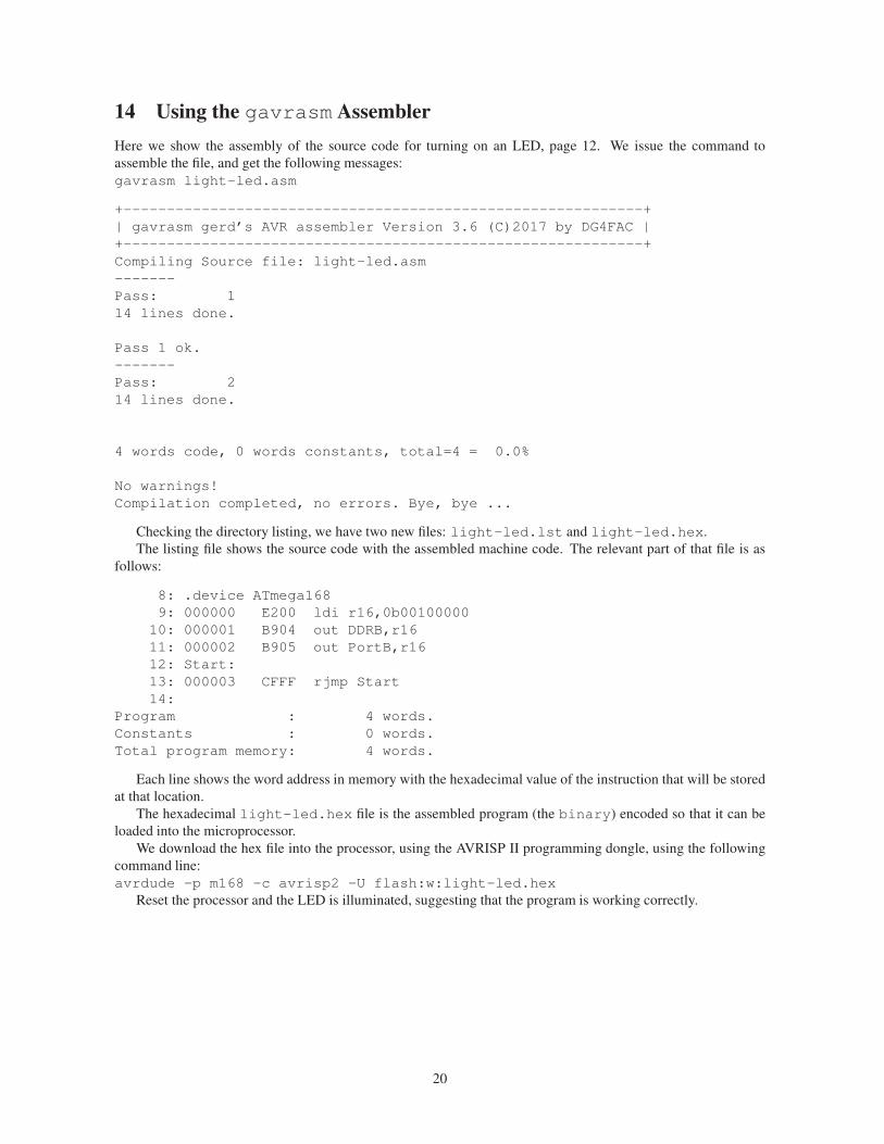
14 Using the gavrasm Assembler
Here we show the assembly of the source code for turning on an LED, page 12. We issue the command to
assemble the file, and get the following messages:
gavrasm light-led.asm
+------------------------------------------------------------+
| gavrasm gerd’s AVR assembler Version 3.6 (C)2017 by DG4FAC |
+------------------------------------------------------------+
Compiling Source file: light-led.asm
-------
Pass: 1
14 lines done.
Pass 1 ok.
-------
Pass: 2
14 lines done.
4 words code, 0 words constants, total=4 = 0.0%
No warnings!
Compilation completed, no errors. Bye, bye ...
Checking the directory listing, we have two new files: light-led.lst and light-led.hex.
The listing file shows the source code with the assembled machine code. The relevant part of that file is as
follows:
8: .device ATmega168
9: 000000 E200 ldi r16,0b00100000
10: 000001 B904 out DDRB,r16
11: 000002 B905 out PortB,r16
12: Start:
13: 000003 CFFF rjmp Start
14:
Program : 4 words.
Constants : 0 words.
Total program memory: 4 words.
Each line shows the word address in memory with the hexadecimal value of the instruction that will be stored
at that location.
The hexadecimal light-led.hex file is the assembled program (the binary) encoded so that it can be
loaded into the microprocessor.
We download the hex file into the processor, using the AVRISP II programming dongle, using the following
command line:
avrdude -p m168 -c avrisp2 -U flash:w:light-led.hex
Reset the processor and the LED is illuminated, suggesting that the program is working correctly.
20
15 Installing and Using Cutecom
To install Cutecom under Ubuntu Linux, enter the following commands into a terminal window:
1. sudo apt-get update
2. sudo apt-get install cutecom lrzsz This gets both the CuteCom and lrzsz packages. The
latter is not necessary, but allows the terminal to sup- port zmodem/xmodem/ymodem file transfer. See:
https://help.ubuntu.com/community/Cutecom.
Now we are ready to connect the Arduino Diecimila unit to the host.
1. Plug the Arduino Diecimila board into a USB port on the host computer.
2. In a terminal window on the Linux host, run the dmesg command. Look at the last few lines to confirm
the connection port. We will assume the port to be \dev\ttyUSB0. (It will be different if you have other
USB-Serial devices plugged into USB ports on the computer.)
3. Run cutecom.
4. Set up the cutecom terminal emulator characteristics as follows:
Device /dev/ttyUSB0
Baud rate 230400
Data bits 8
Stop bits 1
Parity none
Handshake Hardware (Software not selected)
Open for Reading, writing
When you click on the Open Device button, you should see a stream of letters appear on the terminal
display. This is the Arduino Diecimila sending characters to the Linux host.
21
References
[1] AVR Instruction Set
Atmel
http://newit.gsu.by/resources/CPUs%5CAtmel%5CDescribe%5CDATABOOK%
5CCHAP05.PDF
The definitive guide to Atmel AVR machine instructions.
[2] AVR Instruction Set
Atmel
http://www.atmel.com/webdoc/avrassembler/avrassembler.wb_LDD.html
Another list of Atmel AVR machine instructions.
[3] AVR Assembler User Guide
Atmel
http://www.avr-tutorials.com/sites/default/files/AVR%20Assembler%
20User%20Guide.pdf
[4] AVR Assembler 101
Mike Hankey
https://www.codeproject.com/Articles/712610/AVR-Assembler
[5] Tutorial for learning assembly language
Gerhard Schmidt
http://www.avr-asm-tutorial.net/avr_en/index.html
[6] Beginners Introduction to the Assembly Language of ATMEL AVR Microprocessors
Gerhard Schmidt
http://www.avr-asm-download.de/beginner_en.pdf
[7] AVR Assembler Tutorial 11o_o7
http://www.instructables.com/id/Command-Line-Assembly-Language-Programming-for-Ard/
?ALLSTEPS
[8] AVR108: Setup and Use of the LPM Instruction
Atmel
http://www.atmel.com/Images/doc1233.pdf
Assemblers
[9] Gerd’s AVR assembler gavrasm
http://www.avr-asm-tutorial.net/gavrasm/index_en.html
[10] avra - Atmel AVR Assembler
https://sourceforge.net/projects/avra/
[11] http://nerdathome.blogspot.ca/2008/04/avr-as-usage-tutorial.html
Device Programmer Software, Avrdude
[12] AVRDUDE
http://www.nongnu.org/avrdude/
[13] AVRDUDE Manual
http://www.nongnu.org/avrdude/user-manual/avrdude.html#Top
[14] AVRISP MKII doesn’t work with AVRDUDE on Linux
http://stackoverflow.com/questions/5412727/
avrisp-mkii-doesnt-work-with-avrdude-on-linux
22
Monitor programs
[15] KEYMON
Cornell University
https://people.ece.cornell.edu/land/courses/ece4760/keymon/
[16] AVRMON
Steven Bolt
https://sbolt.home.xs4all.nl/Packages/avrmon.txt
Alternative Development Environments
[17] HOWTO: Installing AVRStudio in Ubuntu 8.04
aor_dreamer
http://www.avrfreaks.net/sites/default/files/HOWTO-AVRStudio%20in%20Ubuntu.pdf
[18] Setting up AVR-GCC Toolchain on Linux and Mac OS X
Mayank
http://maxembedded.com/2015/06/setting-up-avr-gcc-toolchain-on-linux-and-mac-os-x/
ATmega168 Datasheet
[19] Atmega168 Datasheet
http://www.atmel.com/Images/Atmel-2545-8-bit-AVR-Microcontroller-ATmega48-88-168_
Datasheet.pdf
The 440 page complete datasheet for the ATmega168, used as an example in this note.
[20] Arduino Diecimila Schematic
https://www.arduino.cc/en/uploads/Main/Arduino-Diecimila-schematic.pdf
ATXmega Circuit Boards
[21] Ready for XMEGA Board, $35US
https://shop.mikroe.com/development-boards/starter/ready/xmega
http://download.mikroe.com/documents/starter-boards/ready/xmega/
ready-xmega-schematic-v100.pdf
https://shop.mikroe.com/accessories?categories
[22] Atmel AVR A1U Xplained Pro $45CDN, Digikey
http://www.atmel.com/tools/ATXMEGAA1U-XPRO.aspx
[23] XMega Utility boards and code
University of New South Wales
http://bionic.gsbme.unsw.edu.au/~philp/HTML_Docs/XMega/
[24] Xmega 4 breakout (2011)
David Watson
https://david.neonquill.com/projects/xmega_breakout/
[25] XMega Breakout Board
Brendan Powers
http://dangerousprototypes.com/forum/viewtopic.php?t=3527&p=35454
Serial Communications
[26] USART
https://sites.google.com/site/qeewiki/books/avr-guide/usart
[27] Simple Serial Communications With AVR Libc
Mika Tuupola
https://www.appelsiini.net/2011/simple-usart-with-avr-libc
23
[28] Serial communication using AVR Microcontroller USART
Akshay Daga
https://www.engineersgarage.com/embedded/avr-microcontroller-projects/
serial-communication-atmega16-usar
[29] Serial Communication
Rod Byrne
https://www.cs.mun.ca/~rod/Winter2007/4723/notes/serial/serial.html
[30] CS 273 Course Notes: Assembly Language Programming with the Atmel AVR Microcontroller
https://www.cs.nmsu.edu/~jcook/arduino/labmanual/booklet/avr-booklet.pdf
24


![Atmel ATSHA204 - SparkFun Electronicscdn.sparkfun.com/.../Atmel-8740-CryptoAuth-ATSHA204-Datasheet.pdf · Atmel ATSHA204 [DATASHEET] 5 Atmel–8740E–CryptoAuth–ATSHA204–Datasheet–022013](https://img.dokumen.tips/doc/110x75/5e25fe64d9a5567efa4c5ccc/atmel-atsha204-sparkfun-atmel-atsha204-datasheet-5-atmela8740eacryptoauthaatsha204adatasheeta022013.jpg)