Embed Size (px)
Citation preview

Assembly InstructionsTuba/Sousaphone
Mobile Storage Rack
©Wenger Corporation 2013 Printed in USA 07/13 Part #148J426-01
Wenger Corporation, 555 Park Drive, P.O. Box 448, Owatonna, Minnesota 55060-0448Questions? Call.....USA: 1-800-4WENGER (493-6437) • Worldwide: 1-507-455-4100 • www.wengercorp.com
CONTENTSImportant User Information . . . . . . . . . . . . . . . . . . . . . . . . . . .2
General . . . . . . . . . . . . . . . . . . . . . . . . . . . . . . . . . . . . . .2Manufacturer . . . . . . . . . . . . . . . . . . . . . . . . . . . . . . . . .2Intended Use . . . . . . . . . . . . . . . . . . . . . . . . . . . . . . . . .2Warranty . . . . . . . . . . . . . . . . . . . . . . . . . . . . . . . . . . . . .2
Required Tools . . . . . . . . . . . . . . . . . . . . . . . . . . . . . . . . . . . .3Fastener Parts List . . . . . . . . . . . . . . . . . . . . . . . . . . . . . . . . .3Parts List . . . . . . . . . . . . . . . . . . . . . . . . . . . . . . . . . . . . . . . . .4Assembly . . . . . . . . . . . . . . . . . . . . . . . . . . . . . . . . . . . . . . . .5Operation . . . . . . . . . . . . . . . . . . . . . . . . . . . . . . . . . . . . . . . .15Replacement Parts . . . . . . . . . . . . . . . . . . . . . . . . . . . . . . . . .16
Note: Please read and understand these instructions before assembling the parts.
Note: Remove all items from the shipping cartons and arrange them in a convenient location. Refer to the illustrations on the following pages. If you need additional information, contact Wenger Corporation using the information below.
Note: For easier assembly, two people are recommended.
4-Unit Model Shown

2
IMPORTANT USER INFORMATIONGENERALCopyright © 2013 by Wenger Corporation
All rights reserved. No part of the contents of this manual may be reproduced, copied, or transmitted inany form or by any means including graphic, electronic, or mechanical methods or photocopying,recording, or information storage and retrieval systems without the written permission of the publisher,unless it is for the purchaser's personal use.
Printed and bound in the United States of America.
The information in this manual is subject to change without notice and does not represent a commitmenton the part of Wenger Corporation. Wenger Corporation does not assume any responsibility for anyerrors that may appear in this manual.
In no event will Wenger Corporation be liable for technical or editorial omissions made herein, nor fordirect, indirect, special, incidental, or consequential damages resulting from the use or defect of thismanual.
The information in this document is not intended to cover all possible conditions and situations that mightoccur. The end user must exercise caution and common sense when assembling or installing WengerCorporation products. If any questions or problems arise, call Wenger Corporation at 1-800-887-7145.
MANUFACTURERThe Tuba/Sousaphone Mobile Storage Rack is manufactured by:
Wenger Corporation555 Park DriveOwatonna, MN 550601-800-4WENGER (493-6437) • 1-507-455-4100www.wengercorp.com
INTENDED USE• This product is intended for indoor use in normal ambient temperature and humidity conditions —
it must not be exposed to prolonged outside weather conditions.• This product is intended to be assembled and used only as described in these instructions.• This product is intended to store typical tuba and sousaphone type instruments only.
WARRANTYThis product is guaranteed free of defects in materials and workmanship for five full years from date of shipment. A full warranty statement is available upon request.

3
FASTENER PARTS LIST
Hex Cap Nut, 1/4-20
11
Machine Screw,1/4-20 x 1.57”
12
Phillips TrussHead Screw, #8 x 5/8”
13
Machine Screw,1/4-20 x .590
14
REQUIRED TOOLSThe following tools are required to assemble the Tuba/Sousaphone Mobile Storage Rack:• Plastic Mallet• Phillips Head Screwdriver or Phillips Head Insert Bit• Variable Speed Drill (to drive hex socket screws)• 1/2” (13 mm) Open End Wrench• 5/32” (4 mm) Hex Insert Bit or Allen Wrench - supplied• 5 mm Hex Wrench - supplied
Fender Washer,3/8 x 2”
15
Wood Screw,7mm x 50mm
16
Carriage Bolt,5/16-18 x 5/8”
17
Lock Nut,5/16-18
18
Wood Dowel,8mm x 25mm
19
Cross Dowel,1/4-20
20
Carriage Bolt,3/8-16 x 1-3/4”
21
Machine Screw,1/4-20 x 2.359”
22
Wing Nut,3/8-16
25
Insert Nut,1/4-20
26
4
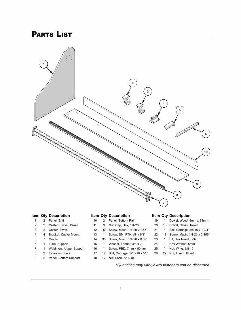
Item Qty Description Item Qty Description Item Qty Description1 2 Panel, End 10 2 Panel, Bottom Rail 19 * Dowel, Wood, 8mm x 25mm2 2 Caster, Swivel, Brake 11 9 Nut, Cap, Hex, 1/4-20 20 13 Dowel, Cross, 1/4-203 2 Caster, Swivel 12 5 Screw, Mach, 1/4-20 x 1.57” 21 * Bolt, Carriage, 3/8-16 x 1-3/4”4 4 Bracket, Caster Mount 13 * Screw, SM, PTH, #8 x 5/8” 22 13 Screw, Mach, 1/4-20 x 2.359”5 * Cradle 14 33 Screw, Mach, 1/4-20 x 0.59” 23 1 Bit, Hex Insert, 5/326 1 Tube, Support 15 * Washer, Fender, 3/8 x 2” 24 1 Hex Wrench, 5mm7 1 Weldment, Upper Support 16 * Screw, PBD, 7mm x 50mm 25 * Nut, Wing, 3/8-168 2 Extrusion, Rack 17 17 Bolt, Carriage, 5/16-18 x 5/8” 26 29 Nut, Insert, 1/4-209 2 Panel, Bottom Support 18 17 Nut, Lock, 5/16-18
1
PARTS LIST
2
6
10
3
4
5
9
8
7
*Quantities may vary, extra fasteners can be discarded.
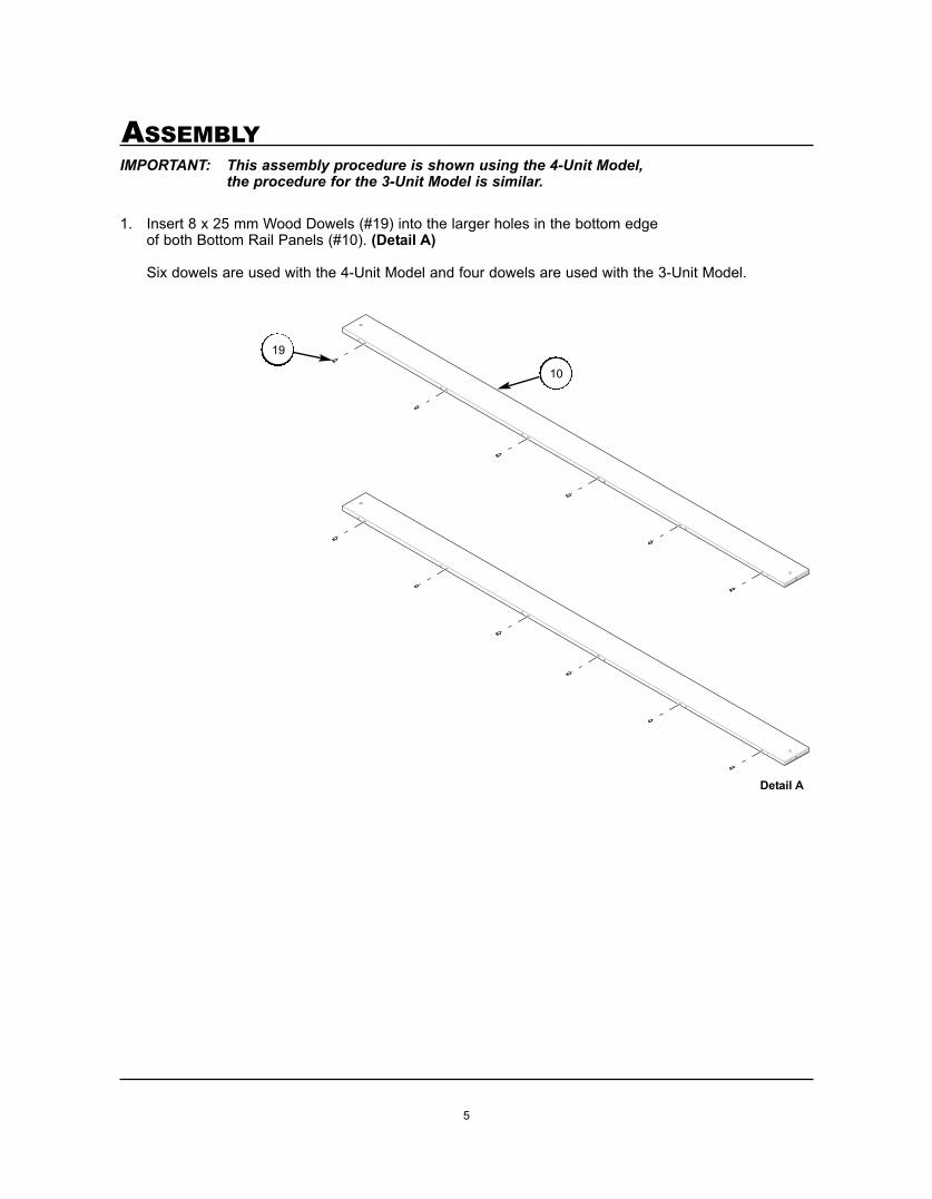
5
ASSEMBLYIMPORTANT: This assembly procedure is shown using the 4-Unit Model,
the procedure for the 3-Unit Model is similar.
1. Insert 8 x 25 mm Wood Dowels (#19) into the larger holes in the bottom edge of both Bottom Rail Panels (#10). (Detail A)
Six dowels are used with the 4-Unit Model and four dowels are used with the 3-Unit Model.
10
Detail A
19
6
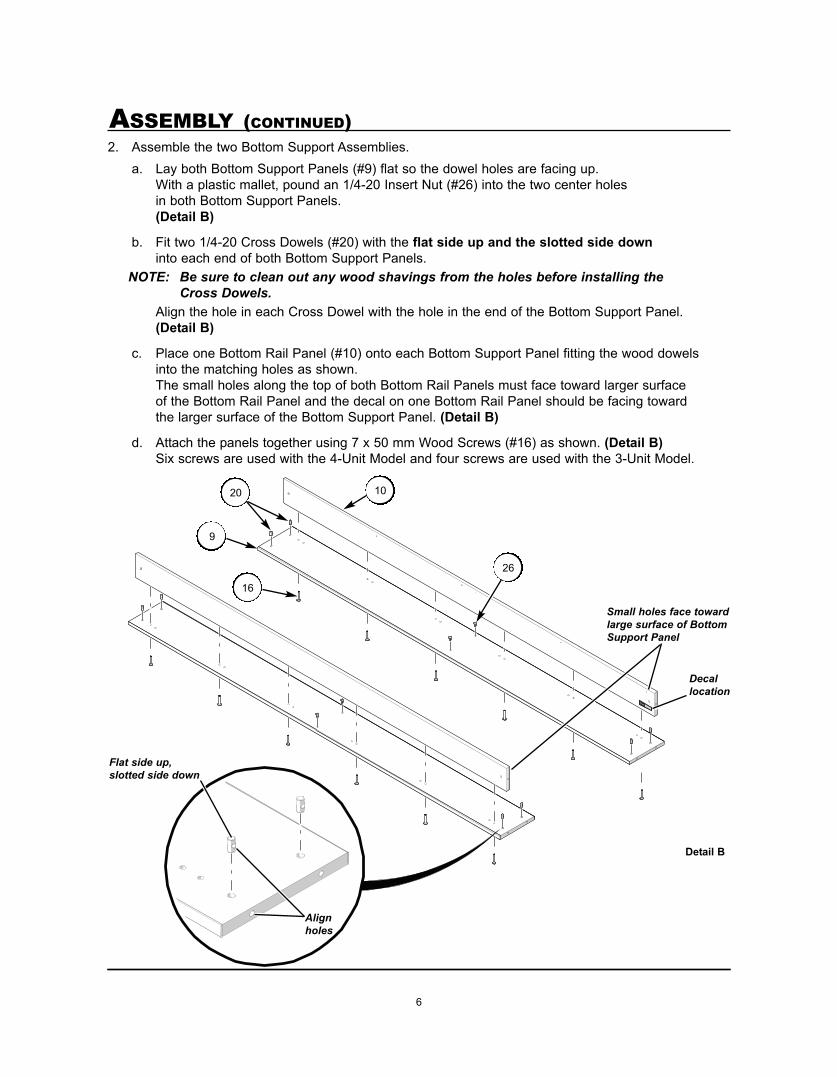
ASSEMBLY (CONTINUED)2. Assemble the two Bottom Support Assemblies.
a. Lay both Bottom Support Panels (#9) flat so the dowel holes are facing up.With a plastic mallet, pound an 1/4-20 Insert Nut (#26) into the two center holes in both Bottom Support Panels.(Detail B)
b. Fit two 1/4-20 Cross Dowels (#20) with the flat side up and the slotted side downinto each end of both Bottom Support Panels.
NOTE: Be sure to clean out any wood shavings from the holes before installing the Cross Dowels.
Align the hole in each Cross Dowel with the hole in the end of the Bottom Support Panel.(Detail B)
c. Place one Bottom Rail Panel (#10) onto each Bottom Support Panel fitting the wood dowels into the matching holes as shown.The small holes along the top of both Bottom Rail Panels must face toward larger surface of the Bottom Rail Panel and the decal on one Bottom Rail Panel should be facing toward the larger surface of the Bottom Support Panel. (Detail B)
d. Attach the panels together using 7 x 50 mm Wood Screws (#16) as shown. (Detail B)Six screws are used with the 4-Unit Model and four screws are used with the 3-Unit Model.
Wenger Corporation
555 Park Drive, P.O. Box 448
Owatonna, MN 55060 U.S.A.
1-507-455-4100
www.wengercorp.com
MADE IN USA OF US AND IMPORTED PARTS
16
Detail B
Alignholes
20 10
9
Decallocation
Flat side up,slotted side down
26
Small holes face towardlarge surface of BottomSupport Panel
7
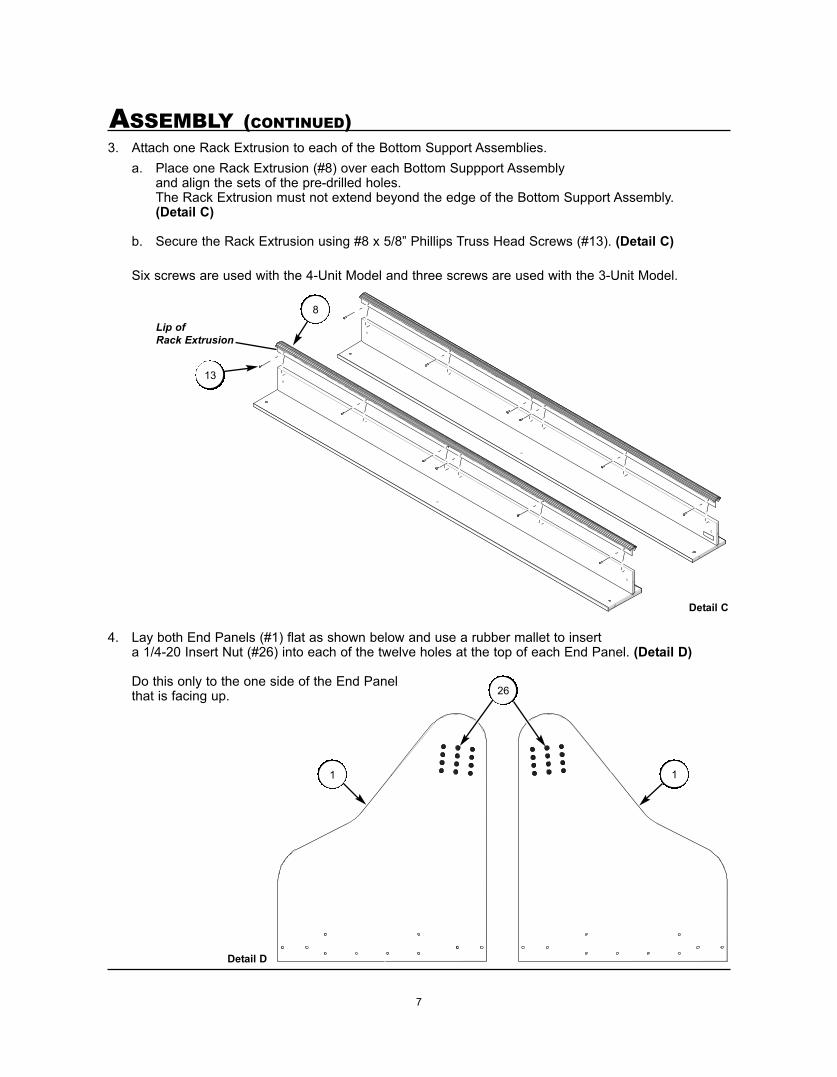
ASSEMBLY (CONTINUED)3. Attach one Rack Extrusion to each of the Bottom Support Assemblies.
a. Place one Rack Extrusion (#8) over each Bottom Suppport Assembly and align the sets of the pre-drilled holes.The Rack Extrusion must not extend beyond the edge of the Bottom Support Assembly. (Detail C)
b. Secure the Rack Extrusion using #8 x 5/8” Phillips Truss Head Screws (#13). (Detail C)
Six screws are used with the 4-Unit Model and three screws are used with the 3-Unit Model.
4. Lay both End Panels (#1) flat as shown below and use a rubber mallet to insert a 1/4-20 Insert Nut (#26) into each of the twelve holes at the top of each End Panel. (Detail D)
Do this only to the one side of the End Panel that is facing up.
Detail C
13
Lip of Rack Extrusion
8
Detail D
26
11

8
ASSEMBLY (CONTINUED)5. Attach the two Bottom Support Assemblies to the End Panels.
Wood strips from the packaging can be used under the Bottom Support Assemblies to raise them off of the floor for this step.a. Fit one 1/4-20 Cross Dowel (#20) with the flat side facing to the inside and
the slotted side facing to the outside into each end of both Bottom Support Panels.Align the hole in each Cross Dowel with the hole in the end of the Bottom Support Assembly.(Detail E)
b. With the lip of both Extrusion Racks facing towards the inside, attach both of the Bottom Support Assemblies to each End Panel (#1) using three 1/4-20 x 2.359 Machine Screws (#22) on each side (two in the Bottom Support panel and one into the Cross Dowel in the Bottom Rail Panel) as shown.The Bottom Support Assembly with the decal should be attached at the rear position.(Detail E)
IMPORTANT: The Insert Nuts installed in the End Panels must face toward the outside on both sides.
1
Detail E
Lips of Rack Extrusionsface to the inside
22
Decallocation
Rear
20
Insert Nuts face toward outside
Wood stripfrom packaging
9
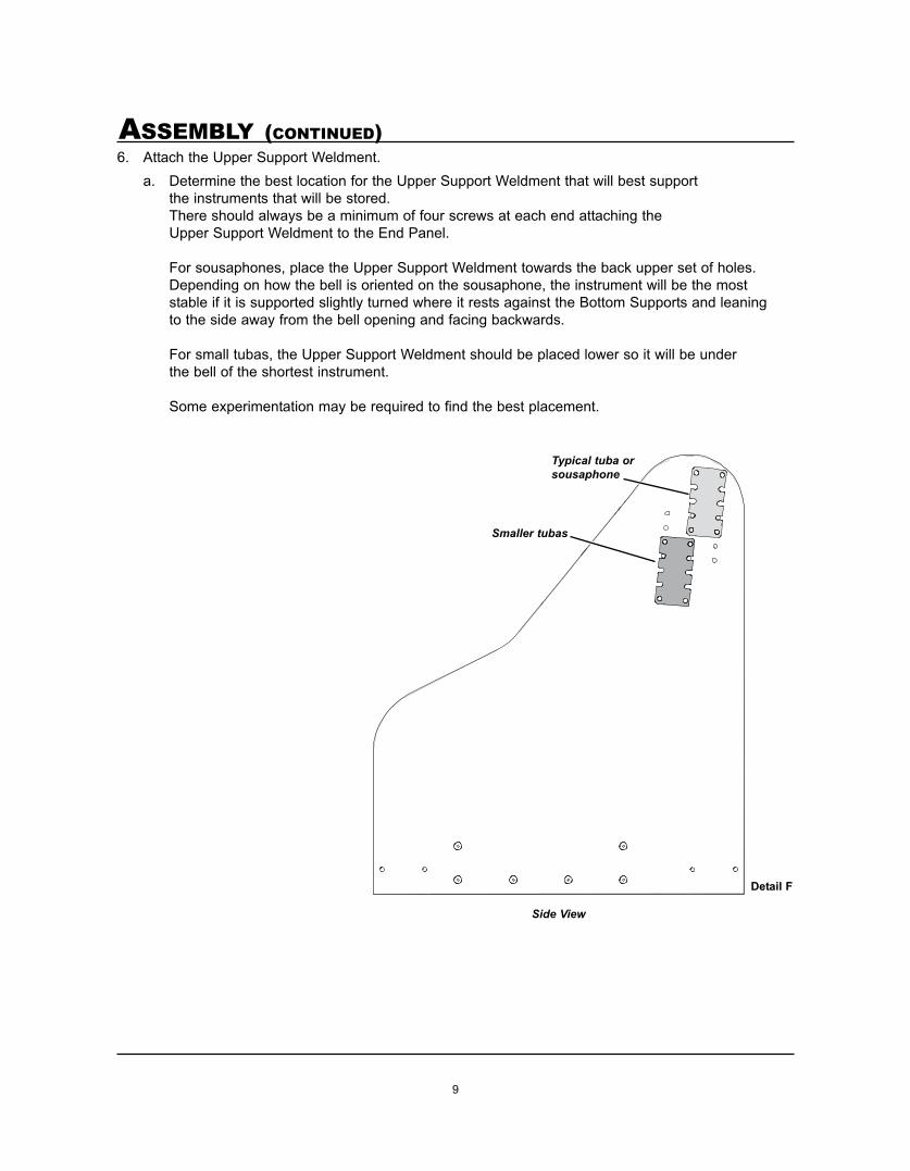
ASSEMBLY (CONTINUED)6. Attach the Upper Support Weldment.
a. Determine the best location for the Upper Support Weldment that will best support the instruments that will be stored.There should always be a minimum of four screws at each end attaching the Upper Support Weldment to the End Panel.
For sousaphones, place the Upper Support Weldment towards the back upper set of holes.Depending on how the bell is oriented on the sousaphone, the instrument will be the most stable if it is supported slightly turned where it rests against the Bottom Supports and leaning to the side away from the bell opening and facing backwards.
For small tubas, the Upper Support Weldment should be placed lower so it will be under the bell of the shortest instrument.
Some experimentation may be required to find the best placement.
Detail F
Typical tuba orsousaphone
Smaller tubas
Side View
10
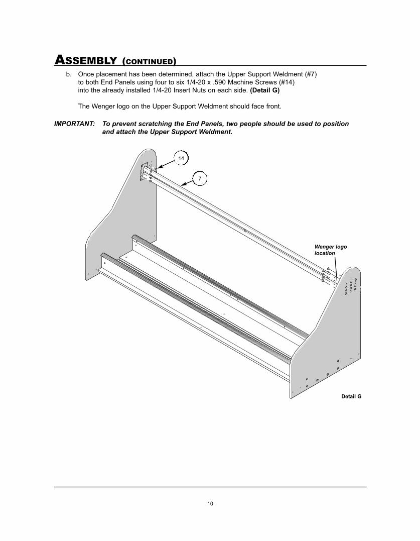
ASSEMBLY (CONTINUED)b. Once placement has been determined, attach the Upper Support Weldment (#7)
to both End Panels using four to six 1/4-20 x .590 Machine Screws (#14) into the already installed 1/4-20 Insert Nuts on each side. (Detail G)
The Wenger logo on the Upper Support Weldment should face front.
IMPORTANT: To prevent scratching the End Panels, two people should be used to position and attach the Upper Support Weldment.
14
7
Detail G
Wenger logolocation

11
ASSEMBLY (CONTINUED)7. Plug the remaining unused upper holes in both End Panels by placing
a 1/4-20 x .590 Machine Screw (#14) into the Insert Nuts.(Detail H)
Detail H
14
8. Preassemble the Casters, two Swivel Brake Casters (#2) and two Swivel Casters (#3) each to a Caster Mount Bracket (#4) using four 5/16-18 x x 5/8” Carriage Bolts (#17) and 5/16-18 Lock Nuts (#18) as shown.(Detail I)
Detail I
18
17
2 3
4
12
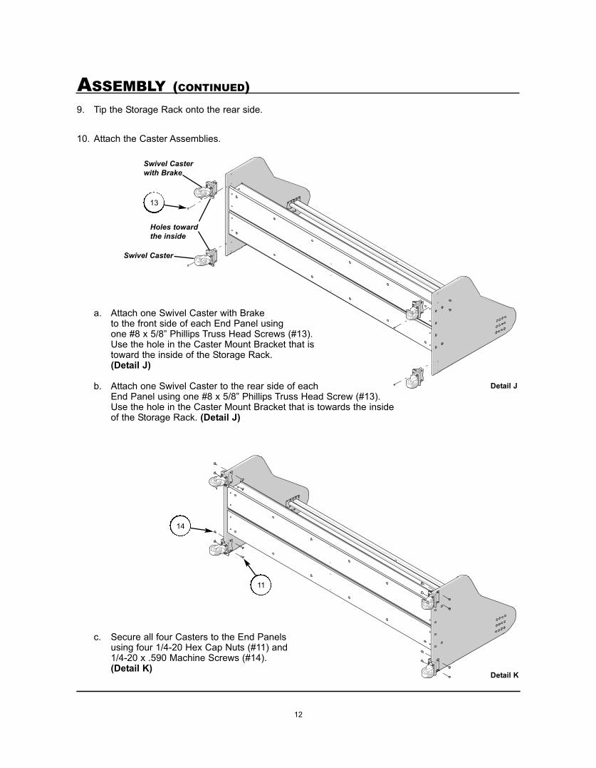
ASSEMBLY (CONTINUED)9. Tip the Storage Rack onto the rear side.
10. Attach the Caster Assemblies.
a. Attach one Swivel Caster with Brake to the front side of each End Panel using one #8 x 5/8” Phillips Truss Head Screws (#13). Use the hole in the Caster Mount Bracket that is toward the inside of the Storage Rack. (Detail J)
b. Attach one Swivel Caster to the rear side of each End Panel using one #8 x 5/8” Phillips Truss Head Screw (#13). Use the hole in the Caster Mount Bracket that is towards the inside of the Storage Rack. (Detail J)
c. Secure all four Casters to the End Panels using four 1/4-20 Hex Cap Nuts (#11) and 1/4-20 x .590 Machine Screws (#14). (Detail K)
Detail J
13
Holes towardthe inside
Detail K
Swivel Casterwith Brake
Swivel Caster
11
14
13
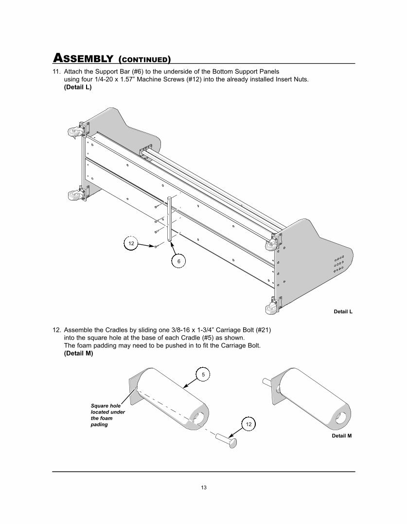
ASSEMBLY (CONTINUED)11. Attach the Support Bar (#6) to the underside of the Bottom Support Panels
using four 1/4-20 x 1.57” Machine Screws (#12) into the already installed Insert Nuts.(Detail L)
12. Assemble the Cradles by sliding one 3/8-16 x 1-3/4” Carriage Bolt (#21) into the square hole at the base of each Cradle (#5) as shown.The foam padding may need to be pushed in to fit the Carriage Bolt.(Detail M)
Detail L
12
Detail M
12
Square holelocated underthe foampading
6
5

14
ASSEMBLY (CONTINUED)13. Attach Cradles (#5) to the bottom of the Storage Rack.
Two Cradles are required for each instrument and should point away from each other in a “V” formation as shown.
Attach each Cradle using one 3/8 x 2” Fender Washer (#15) and 3/8-16 Wing Nut (#25).(Detail N)
14. Tip the Storage Rack upright onto the Casters and attach the remaining Cradles to the Upper Support Weldment as shown.
Detail N
25
5
15

15
OPERATIONThis Storage Rack has been designed to store multiple sizes of Tubas, Sousaphones or a combination of the two.
Instruments should be placed so they lean slightly backwards against the Cradles on the Upper Support Weldment.
Instruments should be placed on the Bottom Supports. Adjust the Cradles by loosening the Wing Nuts and sliding each Cradle to hold the instrument snuggly.
There are four cradles per instrument, two on top and two on the bottom. It is recommended that two people do the adjustment, one to hold the instrument and the other to find the best position for the Cradles.
Sousaphones store best at an angle with top and bottom Cradles not in alignment.It may take some experimentation to get the proper fit. Once the best fit is found, tighten the Wing Nuts and no additional adjustments should be necessary.
Lock the Front Braking Swivel Casters when the Storage Rack is in the desired location. Unlock the casters to move the rack to a different location.
If there are instruments on the Storage Rack while it is being moved, more than one person is required to safely move the Storage Rack through tight spaces. Use caution when pushing the Storage Rack against a wall or moving through doorways as some parts may extend beyond the back.Move the Storage Rack slowly and carefully while holding the instruments in place to prevent them from hitting each other.
16
REPLACEMENT PARTS
Front View
Back View
1
23
4
5
6
7
8
10
9
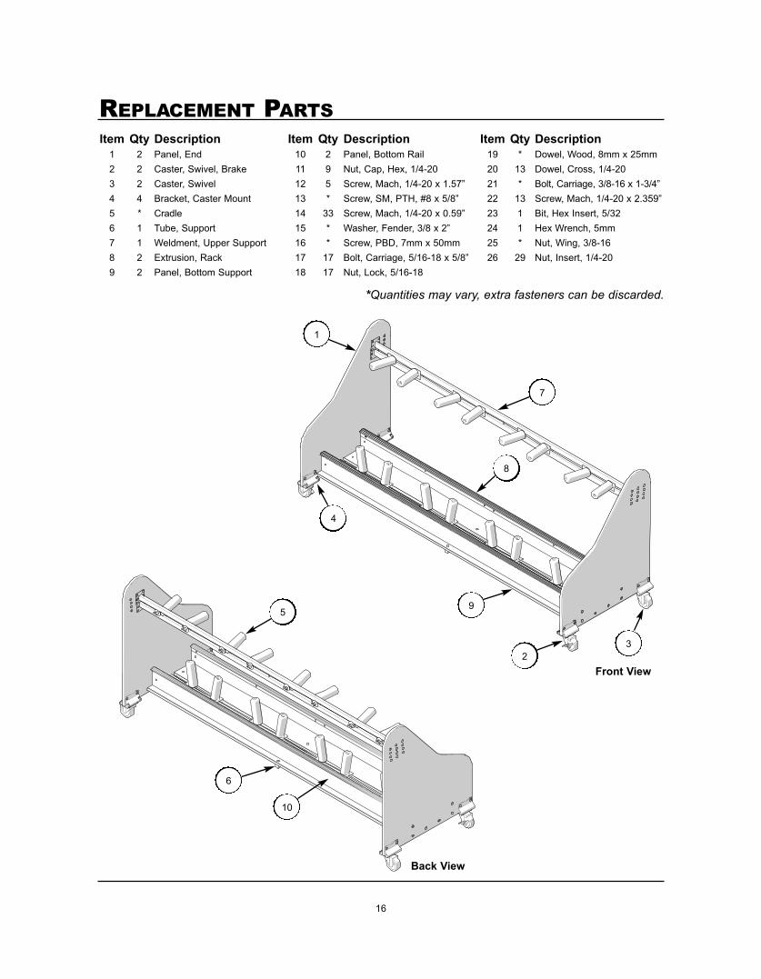
Item Qty Description Item Qty Description Item Qty Description1 2 Panel, End 10 2 Panel, Bottom Rail 19 * Dowel, Wood, 8mm x 25mm2 2 Caster, Swivel, Brake 11 9 Nut, Cap, Hex, 1/4-20 20 13 Dowel, Cross, 1/4-203 2 Caster, Swivel 12 5 Screw, Mach, 1/4-20 x 1.57” 21 * Bolt, Carriage, 3/8-16 x 1-3/4”4 4 Bracket, Caster Mount 13 * Screw, SM, PTH, #8 x 5/8” 22 13 Screw, Mach, 1/4-20 x 2.359”5 * Cradle 14 33 Screw, Mach, 1/4-20 x 0.59” 23 1 Bit, Hex Insert, 5/326 1 Tube, Support 15 * Washer, Fender, 3/8 x 2” 24 1 Hex Wrench, 5mm7 1 Weldment, Upper Support 16 * Screw, PBD, 7mm x 50mm 25 * Nut, Wing, 3/8-168 2 Extrusion, Rack 17 17 Bolt, Carriage, 5/16-18 x 5/8” 26 29 Nut, Insert, 1/4-209 2 Panel, Bottom Support 18 17 Nut, Lock, 5/16-18
*Quantities may vary, extra fasteners can be discarded.