Embed Size (px)
Citation preview
D
GB
F
E
1
9617
9-01
.201
5-DG
bFEI
engineering for a better world GEA Refrigeration Technologies
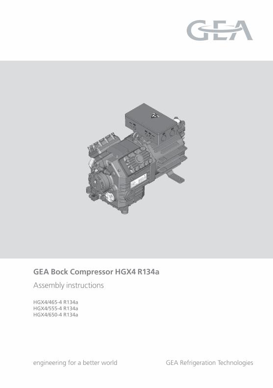
GEA Bock Compressor HGX4 R134a
Assembly instructions
HGX4/465-4 R134aHGX4/555-4 R134aHGX4/650-4 R134a
12
34
5
678910
111213

2
D
GB
F
E
9617
9-01
.201
5-DG
bFEI
About these instructionsRead these instructions before assembly and before using the compressor. This will avoid misunder-standings and prevent damage. Improper assembly and use of the compressor can result in serious or fatal injury. Observe the safety instructions contained in these instructions.These instructions must be passed onto the end customer along with the unit in which the compres-sor is installed.
GEA Bock GmbH
72636 Frickenhausen
GEA Bock GmbH
Benzstraße 7
72636 Frickenhausen
Germany
Telephone +49 7022 9454 0
Fax +49 7022 9454 137
www.gea.com
Manufacturer
Contact
D
GB
F
E
3
9617
9-01
.201
5-DG
bFEI
Contents Page
1 Safety 4 1.1 Identificationofsafetyinstructions 1.2 Qualificationsrequiredofpersonnel 1.3 General safety instructions 1.4 Intended use 2 Product description 6 2.1 Short description 2.2 Name plate 2.3 Type key 3 Areas of application 8 3.1 Refrigerants 3.2 Oil charge 3.3 Limits of application 4 Compressor assembly 10 4.1 Storage and transport 4.2 Setting up 4.3 Pipe connections 4.4 Pipes 4.5 Laying suction and pressure lines 4.6 Operating the shut-off valves 4.7 Operating mode of the lockable service connections 5 Electrical connection 13 5.1 Information for contactor and motor contactor selection 5.2 Standard motor, design for direct or partial winding start 5.3 Basic circuit diagram for part winding start with standard motor 5.4 Special motor: design for direct or star-delta start 5.5 Basic circuit diagram for star-delta start with special motor 5.6 Electronic trigger unit MP 10 5.7 Connecting the trigger unit MP 10 5.8 Functional test of the trigger unit MP 10 5.9 Oil sump heater (accessories) 6 Commissioning 23 6.1 Preparations for start-up 6.2 Pressure strength test 6.3 Leak test 6.4 Evacuation 6.5 Refrigerant charge 6.6 Start-up 6.7 Avoiding slugging 6.8 Connection of oil level regulator 7 Maintenance 25 7.1 Preparation 7.2 Work to be carried out 7.3 Spare parts recommendation 7.4 Accessories 7.5 Extract from the lubricants table 7.6 Decommissioning 8 Technical data 27 9 Dimensions and connections 28 10 Declaration of conformity and installation 30 11 Service 31
4
D
GB
F
E
9617
9-01
.201
5-DG
bFEI
1| Safety
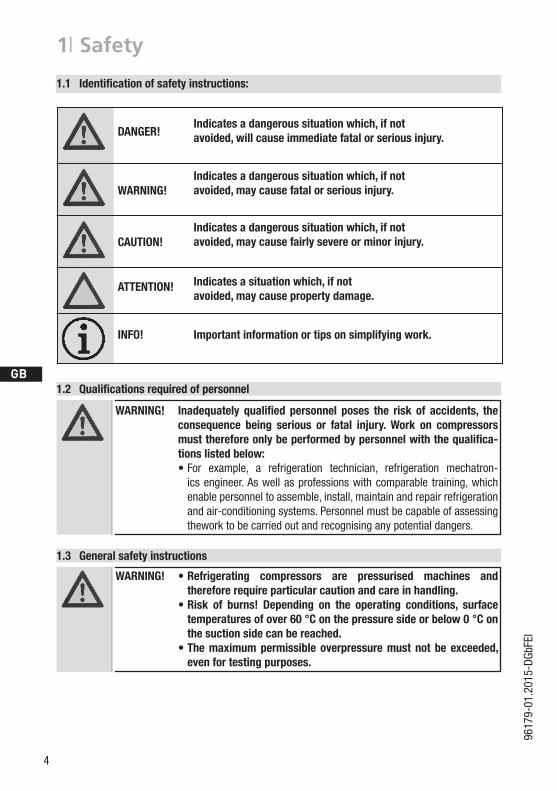
1.2 Qualificationsrequiredofpersonnel
1.3 General safety instructions
WARNING! Inadequately qualified personnel poses the risk of accidents, theconsequence being serious or fatal injury. Work on compressorsmustthereforeonlybeperformedbypersonnelwiththequalifica-tions listed below:
• For example, a refrigeration technician, refrigeration mechatron-ics engineer. As well as professions with comparable training, which enable personnel to assemble, install, maintain and repair refrigeration and air-conditioning systems. Personnel must be capable of assessing thework to be carried out and recognising any potential dangers.
WARNING! • Refrigerating compressors are pressurised machines and thereforerequireparticularcautionandcareinhandling.
• Risk of burns! Depending on the operating conditions, surfacetemperatures of over 60 °C on the pressure side or below 0 °C on the suction side can be reached.
• Themaximumpermissible overpressuremustnotbe exceeded, even for testing purposes.
1.1 Identificationofsafetyinstructions:
DANGER! Indicatesadangeroussituationwhich,ifnot
avoided,willcauseimmediatefatalorseriousinjury.
WARNING! Indicatesadangeroussituationwhich,ifnot
avoided,maycausefatalorseriousinjury.
CAUTION! Indicatesadangeroussituationwhich,ifnot
avoided,maycausefairlysevereorminorinjury.
ATTENTION! Indicatesasituationwhich,ifnot
avoided,maycausepropertydamage.
INFO! Importantinformationortipsonsimplifyingwork.
D
GB
F
E
5
9617
9-01
.201
5-DG
bFEI
1| Safety
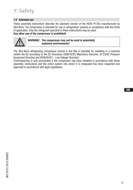
These assembly instructions describe the standard version of the HGX4 R134a manufactured by GEA Bock. The compressor is intended for use in refrigeration systems in compliance with the limits ofapplication.Onlytherefrigerantspecifiedintheseinstructionsmaybeused.Any other use of the compressor is prohibited!
The GEA Bock refrigerating compressor named in the title is intended for installing in a machine (within the EU according to the EU Directives 2006/42/EC Machinery Directive, 97/23/EC Pressure EquipmentDirectiveand2006/95/EC–LowVoltageDirective).Commissioning is only permissible if the compressor has been installed in accordance with these assembly instructions and the entire system into which it is integrated has been inspected and approved in accordance with legal regulations.
1.4 Intended use
WARNING! The compressor may not be used in potentially explosive environments!
6
D
GB
F
E
9617
9-01
.201
5-DG
bFEI
12
34
5
678910
111213
2| Product description
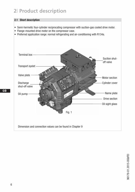
• Semi-hermetic four-cylinder reciprocating compressor with suction-gas cooled drive motor.• Flange-mounted drive motor on the compressor case.• Preferred application range: normal refrigerating and air-conditioning with R134a.
2.1 Short description
Dimension and connection values can be found in Chapter 9
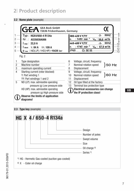
Name plate
Fig. 1
Valveplate
Cylinder cover
Terminal box
Transport eyelet
Discharge shut-off valve
Oil pump
Suction shut-off valve
Oil sight glass
Drive section
Motor section
D
GB
F
E
7
9617
9-01
.201
5-DG
bFEI
12345
6789
10111213
AS35830A006HGX4/650-4 R134a
22,0A84 A 109 A
56,6
67,9SE 55
2| Product description
Fig. 2
2.3 Typekey (example)
¹) HG - Hermetic Gas-cooled (suction gas-cooled)
²) X - Ester oil charge
Design
Number of poles
Swept volume
Size
Oil charge ²)
Series ¹)
1 Typedesignation 6 Voltage,circuit,frequency2 Machine number 7 Nominal rotation speed3 maximum operating current 8 Displacement4 Startingcurrent(rotorblocked) 9 Voltage,circuit,frequency Y: Part winding 1 10 Nominal rotation speed YY: Part windings 1 and 2 11 Displacement5 ND (LP): max. admissible operating 12 Oiltypefilledatthefactory pressure (g) Low pressure side 13 Terminal box protection type HD (HP): max. admissible operating Electrical accessories can change pressure (g) High pressure side the IP protection class! Observe the limits of application diagrams!
50 Hz}
60 Hz}
/HG 4 650-4X R134a
2.2 Name plate (example)
GEA Bock GmbH72636 Frickenhausen, Germany
8
D
GB
F
E
9617
9-01
.201
5-DG
bFEI
3| Areas of application
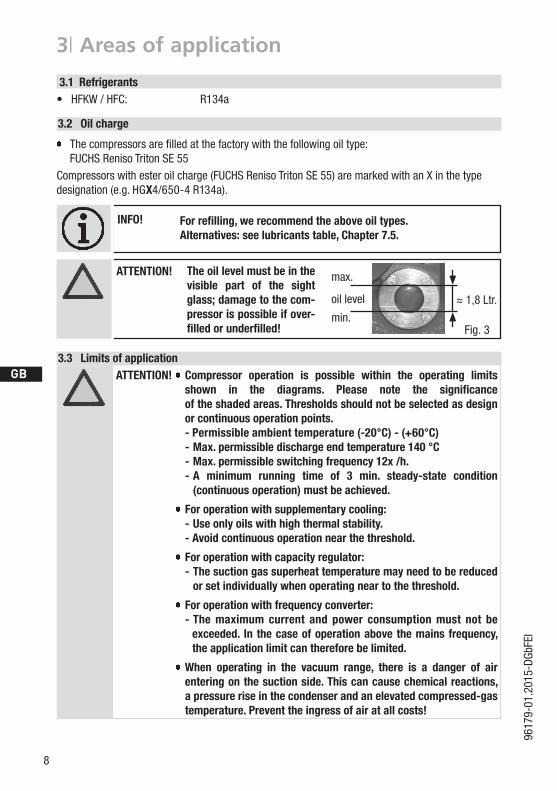
Thecompressorsarefilledatthefactorywiththefollowingoiltype: FUCHS Reniso Triton SE 55 Compressors with ester oil charge (FUCHS Reniso Triton SE 55) are marked with an X in the typedesignation (e.g. HGX4/650-4 R134a).
3.1 Refrigerants• HFKW / HFC: R134a
3.2 Oil charge
ATTENTION! Compressor operation is possible within the operating limits shown in the diagrams. Please note the significance of the shaded areas. Thresholds should not be selected as design or continuous operation points.
- Permissible ambient temperature (-20°C) - (+60°C) - Max. permissible discharge end temperature 140 °C -Max.permissibleswitchingfrequency12x/h. - A minimum running time of 3 min. steady-state condition
(continuous operation) must be achieved.
For operation with supplementary cooling: - Use only oils with high thermal stability. - Avoid continuous operation near the threshold.
For operation with capacity regulator: - The suction gas superheat temperature may need to be reduced
or set individually when operating near to the threshold.
Foroperationwithfrequencyconverter: - The maximum current and power consumption must not be
exceeded. Inthecaseofoperationabovethemainsfrequency,the application limit can therefore be limited.
When operating in the vacuum range, there is a danger of airenteringonthesuctionside.Thiscancausechemicalreactions,a pressure rise in the condenser and an elevated compressed-gas temperature. Prevent the ingress of air at all costs!
3.3 Limits of application
The oil level must be in the visible part of the sight glass; damage to the com-pressor is possible if over-filled or underfilled!
ATTENTION! max.
min.
1,8 Ltr. oil level
Fig. 3
~~
INFO! Forrefilling,werecommendtheaboveoiltypes. Alternatives: seelubricantstable,Chapter7.5.
D
GB
F
E
9
9617
9-01
.201
5-DG
bFEI
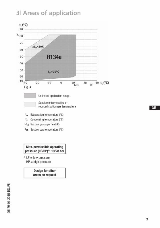
Evaporation temperature (°C)
Condensing temperature (°C)
Suction gas superheat (K)
Suction gas temperature (°C)
Unlimited application range
Supplementary cooling or reduced suction gas temperature
3| Areas of application
Design for other areasonrequest
R134a
Fig. 4
Max. permissible operating pressure (LP/HP)1): 19/28 bar
1) LP = low pressure HP = high pressure
10
D
GB
F
E
9617
9-01
.201
5-DG
bFEI
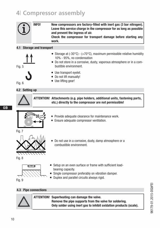
4| Compressor assembly
INFO! Newcompressorsarefactory-filledwithinertgas(3barnitrogen). Leave this service charge in the compressor for as long as possible and prevent the ingress of air.
Check the compressor for transport damage before starting any work.
Setuponanevensurfaceorframewithsufficientload-bearing capacity.
Single compressor preferably on vibration damper. Duplex and parallel circuits always rigid.
Provideadequateclearanceformaintenancework. Ensureadequatecompressorventilation.
Do not use in a corrosive, dusty, damp atmosphere or a combustible environment.
Fig. 7
Fig. 8
Fig. 9
ATTENTION! Superheating can damage the valve. Remove the pipe supports from the valve for soldering. Only solder using inert gas to inhibit oxidation products (scale).
4.3 Pipe connections
F
E
D
C
B
A
1234
F
E
D
C
4 3 2 1
A
BTol.-Ang. DIN ISO 2768-mK
Ra Rz
Maß Passung Freigabe
Alternativbezug:Baumustergeprüft
Teil inaktiv
Lieferantenzeichnung
--
K.-Auftrag:PL:
Zeichnung ungültig
Entwicklungsstand
Teil keine Serie
120400
±0.5
über 0.5bis 6
Benzstraße 7 - 72636 Frickenhausen - Germany - www.bock.de
-
-Unbemaßte Radien:
-
Diese Zeichnung ist unser Eigentum!Sie darf ohne unsere Genehmigung weder nach-gebildet, vervielfältigt, oder Dritten Personen zu-gänglich gemacht werden. Der Nachbau nachdieser Zeichnung, oder an Hand der nach dieserZeichnung hergestellten Gegenstände durch denAbnehmer oder Dritte ist nicht gestattet.Wir behalten uns alle Rechte, gemäß DIN ISO 16016an dieser Zeichnung vor.
Bearb.DatumÄnderungs-Nr.
Werkstoff:
Ausgangsteil, bzw. Rohteil:-
-
Gepr.
NameDatum19.04.
WerkstückkantenDIN ISO 13715
Ersatz für:
Ersetzt durch:
Erstellt2010
Geprüft
-
Kurz
Zone
1/x
Oberflächenbehandlung / Härte:-
Blatt:Änderungsbeschreibung
400Benennung:
±0.8
1000 30 6
-
±0.3
12030
±0.2
Zeichn.-Nr. Teile-Nr.
Oberflächenangaben ISO 1302
x.xxxx-xxxxx.x
Zust.Gußtoleranzen:
Gewicht: (kg)
±0.1
Maßstab:
1:1
Wasserwaagefür Indesign
Der Lieferant muß sicherstellen, dass die Ware ineinwandfreiem Zustand angeliefert wird (Korrosions-schutz, Verpackung für sicheren Transport).
Rz 25Rz 160
s
25
zyxwut
0,05 Rz 1,60,30,71,62 Rz 166,3 Rz 63 Rz 6,3Rz 12,5
F:\u
ser\k
urz\
3D S
ache
n\3D
Tei
le\Z
eich
nung
en\W
asse
rwaa
ge
4.2 Setting up
?4.1 Storage and transport
Use transport eyelet. Do not lift manually! Use lifting gear!
Storage at (-30°C) - (+70°C), maximum permissible relative humidity 10% - 95%, no condensation
Do not store in a corrosive, dusty, vaporous atmosphere or in a com-bustible environment.
Fig. 6
Fig. 5
ATTENTION! Attachments(e.g.pipeholders,additionalunits,fasteningparts,etc.) directly to the compressor are not permissible!
D
GB
F
E
11
9617
9-01
.201
5-DG
bFEI
12
34
5
678910
111213
12
34
5
678910
111213
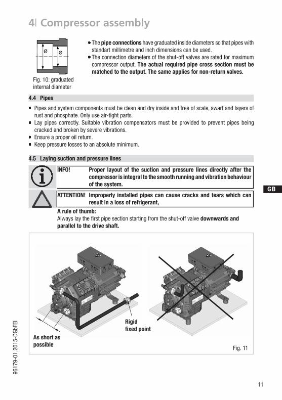
4.5 Laying suction and pressure lines
INFO! Proper layout of the suction and pressure lines directly after the compressor is integral to the smooth running and vibration behaviour of the system.
ATTENTION! Improperly installedpipescancausecracksand tearswhichcanresultinalossofrefrigerant,
A rule of thumb:Alwayslaythefirstpipesectionstartingfromtheshut-offvalvedownwards andparallel to the drive shaft.
4| Compressor assembly
4.4 Pipes
Pipes and system components must be clean and dry inside and free of scale, swarf and layers of rust and phosphate. Only use air-tight parts.
Lay pipes correctly. Suitable vibration compensators must be provided to prevent pipes being cracked and broken by severe vibrations.
Ensure a proper oil return. Keep pressure losses to an absolute minimum.
The pipe connections have graduated inside diameters so that pipes with standart millimetre and inch dimensions can be used. The connection diameters of the shut-off valves are rated for maximum compressor output. Theactualrequiredpipecrosssectionmustbematched to the output. The same applies for non-return valves.
Fig. 10: graduated internal diameter
Fig. 11
Rigid fixed point
As short as possible
12
D
GB
F
E
9617
9-01
.201
5-DG
bFEI
4| Compressor assembly
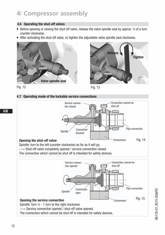
4.6 Operating the shut-off valves Before opening or closing the shut-off valve, release the valve spindle seal by approx. ¼ of a turn
counter-clockwise. After activating the shut-off valve, re-tighten the adjustable valve spindle seal clockwise.
Pipe connection
Pipe connection
4.7 Operatingmodeofthelockableserviceconnections
Fig. 14Opening the shut-off valve:Spindle: turn to the left (counter-clockwise) as far as it will go. —> Shut-off valve completely opened / service connection closed.The connection which cannot be shut off is intended for safety devices.
Fig. 15Opening the service connectionSpindle: Turn ½ - 1 turn to the right clockwise. —> Service connection opened / shut-off valve opened.The connection which cannot be shut off is intended for safety devices.
Service connec-tion closed
Connectionblocked
Spindle
Connection cannot be shut off
Connection cannot be shut off
Service connec-tion opened
SpindleConnectionopen
Compressor
Compressor
Fig. 12 Fig. 13
Valve spindle seal
ReleaseTighten
D
GB
F
E
13
9617
9-01
.201
5-DG
bFEI
5| Electrical connection
5 Electrical connection
DANGER! Highvoltage!Riskofelectricshock!Onlycarryoutworkwhentheelectrical system is disconnected from the power supply!
INFO! Connect the compressor motor in accordance with the circuit diagram (see inside of terminal box).
Use suitable cable entry point of the correct protection type (see name plate) for routing cables into the terminal box. Insert the strain reliefs and prevent chafe marks on the cables.
Comparethevoltageandfrequencyvalueswiththedataforthemainspower supply.
Only connect the motor if these values are the same.
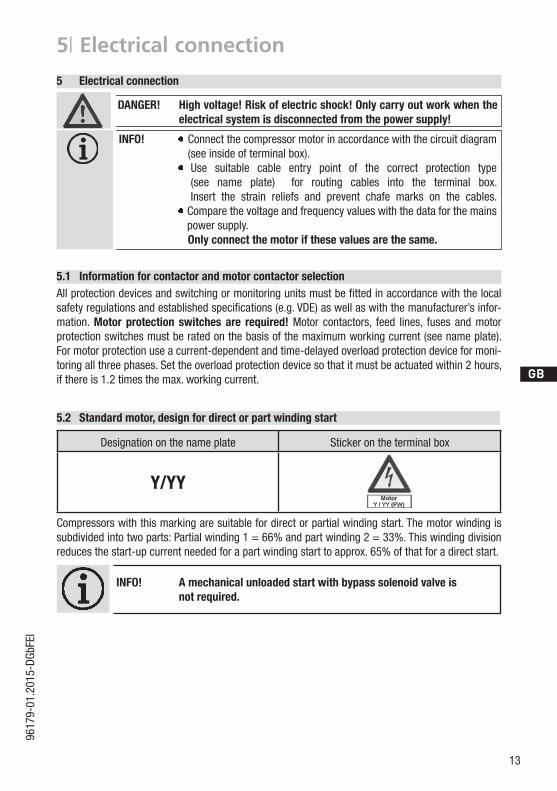
5.2 Standardmotor,designfordirectorpartwindingstart
Designation on the name plate Sticker on the terminal box
Y/YY
Compressors with this marking are suitable for direct or partial winding start. The motor winding is subdivided into two parts: Partial winding 1 = 66% and part winding 2 = 33%. This winding division reduces the start-up current needed for a part winding start to approx. 65% of that for a direct start.
INFO! A mechanical unloaded start with bypass solenoid valve is notrequired.
5.1 Information for contactor and motor contactor selectionAllprotectiondevicesandswitchingormonitoringunitsmustbefittedinaccordancewiththelocalsafetyregulationsandestablishedspecifications(e.g.VDE)aswellaswiththemanufacturer’sinfor-mation. Motorprotection switchesare required! Motor contactors, feed lines, fuses and motor protection switches must be rated on the basis of the maximum working current (see name plate). For motor protection use a current-dependent and time-delayed overload protection device for moni-toring all three phases. Set the overload protection device so that it must be actuated within 2 hours, if there is 1.2 times the max. working current.
14
D
GB
F
E
9617
9-01
.201
5-DG
bFEI
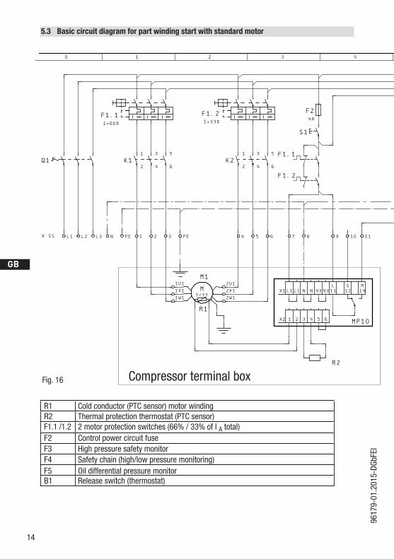
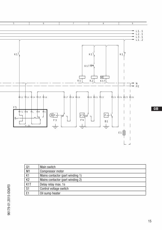
5.3 Basic circuit diagram for part winding start with standard motor
R1 Cold conductor (PTC sensor) motor windingR2 Thermal protection thermostat (PTC sensor)F1.1 /1.2 2 motor protection switches (66% / 33% of I A total)F2 Control power circuit fuseF3 High pressure safety monitorF4 Safety chain (high/low pressure monitoring)F5 Oil differential pressure monitorB1 Release switch (thermostat)
Fig. 16
�nderung
0
Datum Name
Datum
Bearb.
Gepr.
Norm
1
20.Feb.2009
Kelich
09.M„r.2010
Urspr.
2
Ers.f.
3
Ers.d.
4
PWMP10
5 6 7
BOCKCOMPRESSORS
8
=
+
9
Bl.
1 Bl.
1
XSS
Q1
L1 L2 L3 N PE
AnschluákastenVerdichter
I=66%
F1.1
K11
2
1
3
4
2
5
6
3
1U1
1V1
1W1
PE
MY/YY
M1
R1
2U1
2V1
2W1
I=33%
F1.2
K21
2
4
3
4
5
5
6
6
X1L1L1 N N 434311 12 14L S M
X2 1 2 3 4 5 6
7
F1.1
F1.2
8
R2
4A
F2
S1
9 10
MP10
11
F5
K1
12
T2
13
N
P™l
14
L
15
M
16
S
P>
F3
17 18 19
K1
P
F4
20
K1
K1T
K2
21 22
K1T
P<
B1
23 24
K1
25
E1
26
L1.1L2.1L3.1L1.2
NPE
Compressor terminal box
D
GB
F
E
15
9617
9-01
.201
5-DG
bFEI
Q1 Main switchM1 Compressor motorK1 Mains contactor (part winding 1)K2 Mains contactor (part winding 2)K1T Delay relay max. 1sS1 Control voltage switchE1 Oil sump heater
�nderung
0
Datum Name
Datum
Bearb.
Gepr.
Norm
1
20.Feb.2009
Kelich
09.M„r.2010
Urspr.
2
Ers.f.
3
Ers.d.
4
PWMP10
5 6 7
BOCKCOMPRESSORS
8
=
+
9
Bl.
1 Bl.
1
XSS
Q1
L1 L2 L3 N PE
AnschluákastenVerdichter
I=66%
F1.1
K11
2
1
3
4
2
5
6
3
1U1
1V1
1W1
PE
MY/YY
M1
R1
2U1
2V1
2W1
I=33%
F1.2
K21
2
4
3
4
5
5
6
6
X1L1L1 N N 434311 12 14L S M
X2 1 2 3 4 5 6
7
F1.1
F1.2
8
R2
4A
F2
S1
9 10
MP10
11
F5
K1
12
T2
13
N
P™l
14
L
15
M
16
S
P>
F3
17 18 19
K1
P
F4
20
K1
K1T
K2
21 22
K1T
P<
B1
23 24
K1
25
E1
26
L1.1L2.1L3.1L1.2
NPE
16
D
GB
F
E
9617
9-01
.201
5-DG
bFEI
5| Electrical connection
400 V
Direktstart YY Teilwicklungsstart Y/YY
1V1 1W11U1
2W12V12U1
L3L2L1 L3L2L1
L3L2L1
1V1 1W11U1
2W12V12U1
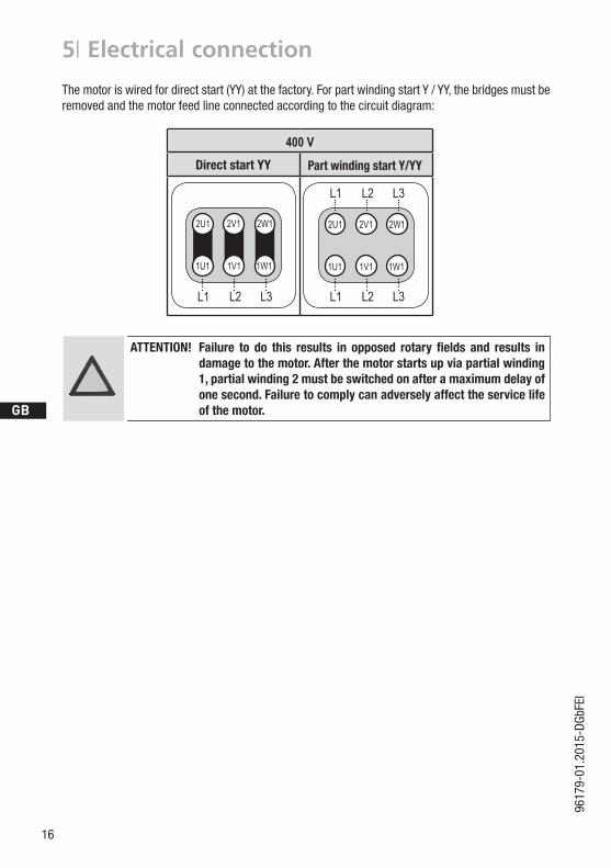
Direct start YY Part winding start Y/YY
ATTENTION! Failure to do this results in opposed rotary fields and results indamage to the motor. After the motor starts up via partial winding 1,partialwinding2mustbeswitchedonafteramaximumdelayofone second. Failure to comply can adversely affect the service life of the motor.
The motor is wired for direct start (YY) at the factory. For part winding start Y / YY, the bridges must be removed and the motor feed line connected according to the circuit diagram:
D
GB
F
E
17
9617
9-01
.201
5-DG
bFEI
5| Electrical connection
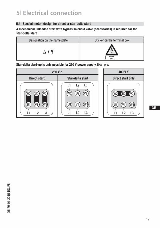
5.4 Special motor: design for direct or star-delta start
Amechanicalunloadedstartwithbypasssolenoidvalve(accessories)isrequiredforthestar-delta start.
Designation on the name plate Sticker on the terminal box
∆ / Y
Star-delta start-up is only possible for 230 V power supply. Example:
230 V ∆
Direct start Star-delta start
400 V Y
Direct start only
5.4 Sondermotor: Ausführung für Direkt- oder Stern-Dreieck-Anlauf
Für den Stern-Dreieck-Anlauf ist eine mechanische Anlaufentlastung mit Bypass-Magnetventil (Zubehör) erforderlich.
Bezeichnung auf dem Typschild Aufkleber auf Klemmenkasten
∆ / Y
Stern-Dreieck-Anlauf ist nur im Spannungsbereich ∆ (230 V) möglich. Beispiel:
230 V ∆
Direktstart Stern-Dreieck-Start
L3L1
V1 W1U1
V2U2W2
L1 L2 L3
L2
V1 W1U1
V2U2W2
L3L2L1
400 V Y
nur Direktstart
V1 W1U1
V2U2W2
L1 L2 L3
18
D
GB
F
E
9617
9-01
.201
5-DG
bFEI
�nderung
0
Datum Name
Datum
Bearb.
Gepr.
Norm
1
20.Feb.2009
Kelich
09.M„r.2010
Urspr.
2
Ers.f.
3
Ers.d.
4
D/S
MP10
5 6 7
BOCKCOMPRESSORS
8
=
+
9
Bl.
1 Bl.
1
XSS
Q1
L1 L2 L3 N PE
F1.1
K11
2
F1.2
1
AnschluákastenVerdichter
3
4
2
5
6
3 PE
U1
V1
W1
M3~
M1
Y
K31
2
3
4
R1
5
6
W2
U2
V2
D
K21
2
4
3
4
5
5
6
6
X1L1L1 N N 434311 12 14L S M
X2 1 2 3 4 5 6
7
F1.1
F1.2
8
R2
4A
F2
S1
9 10
MP10
11
F5
K1
12
T2
13
N
P™l
14
L
15
M
16
S
K1
K1
K3
P>
F3
K4T
K3
K2
17
K4T
K2
K3
18 19
K4T
P
F4
20
K5T
AL
21 22
K5T
P<
B1
23 24
K1
25
E1
26
L1.1L2.1L3.1L1.2
NPE
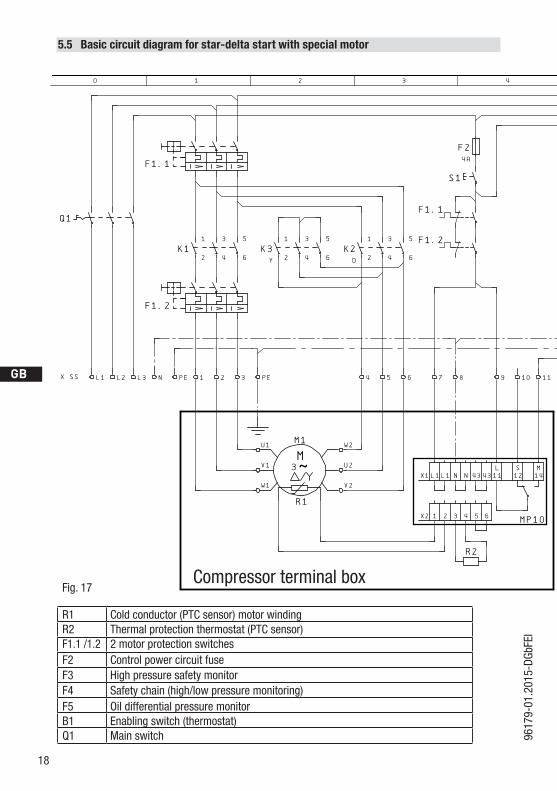
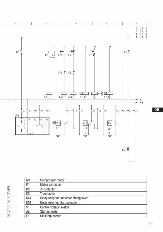
5.5 Basic circuit diagram for star-delta start with special motor
Fig. 17
R1 Cold conductor (PTC sensor) motor windingR2 Thermal protection thermostat (PTC sensor)F1.1 /1.2 2 motor protection switchesF2 Control power circuit fuseF3 High pressure safety monitorF4 Safety chain (high/low pressure monitoring)F5 Oil differential pressure monitorB1 Enabling switch (thermostat)Q1 Main switch
Compressor terminal box
D
GB
F
E
19
9617
9-01
.201
5-DG
bFEI
�nderung
0
Datum Name
Datum
Bearb.
Gepr.
Norm
1
20.Feb.2009
Kelich
09.M„r.2010
Urspr.
2
Ers.f.
3
Ers.d.
4
D/S
MP10
5 6 7
BOCKCOMPRESSORS
8
=
+
9
Bl.
1 Bl.
1
XSS
Q1
L1 L2 L3 N PE
F1.1
K11
2
F1.2
1
AnschluákastenVerdichter
3
4
2
5
6
3 PE
U1
V1
W1
M3~
M1
Y
K31
2
3
4
R1
5
6
W2
U2
V2
D
K21
2
4
3
4
5
5
6
6
X1L1L1 N N 434311 12 14L S M
X2 1 2 3 4 5 6
7
F1.1
F1.2
8
R2
4A
F2
S1
9 10
MP10
11
F5
K1
12
T2
13
N
P™l
14
L
15
M
16
S
K1
K1
K3
P>
F3
K4T
K3
K2
17
K4T
K2
K3
18 19
K4T
P
F4
20
K5T
AL
21 22
K5T
P<
B1
23 24
K1
25
E1
26
L1.1L2.1L3.1L1.2
NPE
M1 Compressor motorK1 Mains contactorK2 ∆-contactorK3 Y-contactorK4T Delay relay for contactor changeoverK5T Delay relay for start unloaderS1 Control voltage switchAL Start unloaderE1 Oil sump heater
20
D
GB
F
E
9617
9-01
.201
5-DG
bFEI
5| Electrical connection
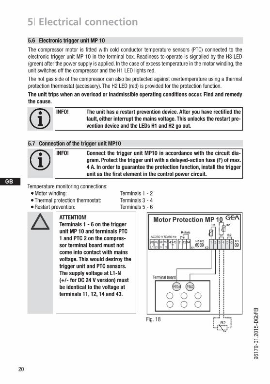
ATTENTION! Terminals 1 - 6 on the trigger unit MP 10 and terminals PTC 1 and PTC 2 on the compres-sor terminal board must not come into contact with mains voltage. This would destroy the trigger unit and PTC sensors.The supply voltage at L1-N (+/- for DC 24 V version) must be identical to the voltage at terminals11,12,14and43.
5.6 Electronic trigger unit MP 10
The compressormotor is fittedwith cold conductor temperature sensors (PTC) connected to theelectronic trigger unit MP 10 in the terminal box. Readiness to operate is signalled by the H3 LED (green) after the power supply is applied. In the case of excess temperature in the motor winding, the unit switches off the compressor and the H1 LED lights red.
The hot gas side of the compressor can also be protected against overtemperature using a thermal protection thermostat (accessory). The H2 LED (red) is provided for the protection function.
The unit trips when an overload or inadmissible operating conditions occur. Find and remedy the cause.
5.7 Connection of the trigger unit MP10
INFO! Connect the trigger unit MP10 in accordance with the circuit dia-gram. Protect the trigger unit with a delayed-action fuse (F) of max. 4A.Inordertoguaranteetheprotectionfunction,installthetriggerunitasthefirstelementinthecontrolpowercircuit.
Temperature monitoring connections: Motor winding: Terminals 1 - 2 Thermal protection thermostat: Terminals 3 - 4 Restart prevention: Terminals 5 - 6
INFO! Theunithasarestartpreventiondevice.Afteryouhaverectifiedthefault,eitherinterruptthemainsvoltage.Thisunlockstherestartpre-vention device and the LEDs H1 and H2 go out.
Terminal board
Fig. 18
D
GB
F
E
21
9617
9-01
.201
5-DG
bFEI
5| Electrical connection
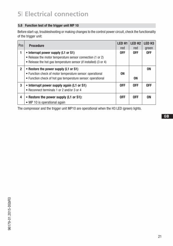
The compressor and the trigger unit MP10 are operational when the H3 LED (green) lights.
5.8 Function test of the trigger unit MP 10
Pos ProcedureLED H1 LED H2 LED H3
red red green1 • Interrupt power supply (L1 or S1) OFF OFF OFF
• Release the motor temperature sensor connection (1 or 2)• Release the hot gas temperature sensor (if installed) (3 or 4)
2 • Restore the power supply (L1 or S1) ON• Function check of motor temperature sensor: operational ON• Function check of hot gas temperature sensor: operational ON
3 • Interrupt power supply again (L1 or S1) OFF OFF OFF• Reconnect terminals 1 or 2 and/or 3 or 4
4 • Restore the power supply (L1 or S1): OFF OFF ON• MP 10 is operational again
Before start-up, troubleshooting or making changes to the control power circuit, check the functionality of the trigger unit:
22
D
GB
F
E
9617
9-01
.201
5-DG
bFEI
5| Electrical connection
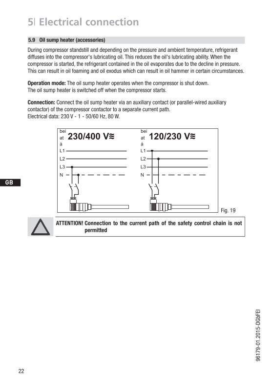
5.9 Oil sump heater (accessories)
Anschlussschema für ÖlsumpfheizungConnection diagramm for oil sump heater Plan de raccordement pour résistance de carter d‘huile
0998
3- 10
.01-D
GBF
DGBF
During compressor standstill and depending on the pressure and ambient temperature, refrigerant diffuses into the compressor's lubricating oil. This reduces the oil's lubricating ability. When the compressor is started, the refrigerant contained in the oil evaporates due to the decline in pressure. This can result in oil foaming and oil exodus which can result in oil hammer in certain circumstances.
Operation mode: The oil sump heater operates when the compressor is shut down. The oil sump heater is switched off when the compressor starts.
Connection: Connect the oil sump heater via an auxiliary contact (or parallel-wired auxiliary contactor) of the compressor contactor to a separate current path.Electricaldata:230V-1-50/60Hz,80W.
ATTENTION! Connection to the current path of the safety control chain is not permitted
Fig. 19
D
GB
F
E
23
9617
9-01
.201
5-DG
bFEI
6| Commissioning
6.1 Preparations for start-up
6.4 Evacuation
First evacuate the system and then include the compressor in the evacuation process. Relieve the compressor pressure. Open the suction and pressure line shut-off valves. Evacuate the suction and discharge pressure sides using the vacuum pump. At the end of the evacuation process, the vacuum should be < 1.5 mbar when the pump is switched off. Repeatthisprocessasoftenasisrequired.
ATTENTION! Do not start the compressor if it is under vacuum. Do not apply any voltage - even for test purposes (must only be operated with refrigerant).
Under vacuum, the spark-over and creepage current distances of the terminal board connection bolts shorten; this can result in winding and terminal board damage.
INFO! In order to protect the compressor against inadmissible operating conditions,high-pressureandlow-pressurepressostatscontrolsaremandatory on the installation side.
The compressor has undergone trials in the factory and all functions have been tested. There are therefore no special running-in instructions.
Checkthecompressorfortransportdamage!
6.2 Pressure strength test
DANGER! Bursting! The compressor must only be pressurised using nitrogen (N2). Never pressurise with oxygen or other gases!
The maximum permissible overpressure of the compressor must not be exceeded at any time during the testing process (see name plate data)! Do not mix any refrigerant with the nitrogen as this could cause the ignition limit to shift into the critical range.
The compressor has been factory-tested for pressure resistance. The following must be observed if the entire plant is subjected to an additional pressure strength test:
Test the refrigeration circuit according to EN 378-2 or a corresponding safety standard.
6.3 Leaktest
DANGER! Bursting! Do not mix any refrigerant with the nitrogen (N2) as this could cause
the ignition limit to shift into the critical range.
Carry out the leak test of the refrigerating system in accordance with EN 378-2 or a corresponding safety standard without including the compressor.
24
D
GB
F
E
9617
9-01
.201
5-DG
bFEI
6| Commissioning
CAUTION! Wear personal protective clothing such as goggles and protective gloves!
Make sure that the suction and pressure line shut-off valves are open.
Withthecompressorswitchedoff,addtheliquidrefrigerantdirectlytothecondenserorreceiver,breaking the vacuum.
If the refrigerant needs topping up after starting the compressor, it can be topped up in vapour formonthesuctionside,or,takingsuitableprecautions,alsoinliquidformattheinlettotheevaporator.
INFO! Avoidoverfillingthesystemwithrefrigerant! In order to prevent shifts in concentration, zeotropic refrigerant
blends (e.g. R407C) must always only be added to the refrigerating systeminliquidform.
Do not pour liquid refrigerant through the suction line shut-offvalve on the compressor.
It is not permissible to mix additives with the oil and refrigerant.
6.5 Refrigerant charge
6.6 Start-up
WARNING! Ensure that both shut-off valves are open before starting the compressor!
Check that the safety and protection devices (pressure switch, motor protection, electrical con-tact protection measures, etc.) are functioning properly.
Switch on the compressor and let it run for at least 10 minutes. Check the oil level : The oil must be visible in the sight glass.
ATTENTION!Iflargerquantitiesofoilhavetobetoppedup,thereisariskofoilimpacteffects.Ifthisisthecase,checktheoilreturn!
6.7 Avoid slugging
ATTENTION! Slugging can result in damage to the compressor and cause refrigeranttoleak.
To prevent slugging: The complete refrigeration plant must be properly designed. All components must be compatibly rated with each other with regard to output (particularly the
evaporator and expansion valves). Suction gas superheating at the compressor input should be min. 7 - 10 K (check the setting of
the expansion valve). Thesystemmustreachastateofequilibrium. Particularlyincriticalsystems(e.g.severalevaporatorpoints),measuressuchastheuseofliquidtraps,solenoidvalveintheliquidline,etc.arerecommended. There should be no movement of refrigerant in the compressor while the system is at a standstill.
D
GB
F
E
25
9617
9-01
.201
5-DG
bFEI
7.1 Preparation
7.2 Worktobecarriedout
7| Maintenance
In order to guarantee optimum operational reliability and service life of the compressor, we recommend carrying out servicing and inspection work at regular intervals: Oil change:
- not mandatory for factory-produced series systems. - forfieldinstallationsorwhenoperatingneartheapplicationlimit:forthefirsttimeafter100
to 200 operating hours, then approx. every 3 years or 10,000 - 12,000 operating hours. Dispose of used oil according to the regulations; observe national regulations.
Annual checks: Oil level, leak tightness, running noises, pressures, temperatures, function of auxiliary devices such as oil sump heater, pressure switch.
WARNING! Beforestartinganyworkonthecompressor: Switch off the compressor and secure it to prevent a restart. Relieve compressor of system pressure. Preventairfrominfiltratingthesystem! After maintenance has been performed: Connect safety switch. Evacuate compressor. Releaseswitch-onlock.
6.8 Connection of oil level regulator
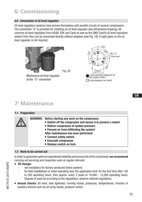
Oil level regulation systems have proven themselves with parallel circuits of several compressors. The connection "0" is provided for installing an oil level regulator (see dimensions drawing). All common oil level regulators from AC&R, ESK and Carly as well as the OM3 TraxOil oil level regulation system from Alco can be connected directly without adapters (see Fig. 18). A sight glass on the oil levelregulatorisnotrequired.
Mechanical oil level regulatorat the "O" connection
Fig. 20
6| Commissioning
Schmierung / Ölkontrolle Bei Inbetriebnahme Öldruckkontrolle mittels Manometer über
den Schraderanschluss an der Ölpumpe vornehmen. Nach Erreichen des Beharrungszustands (kontinuierliche
Betriebsbedingung) Ölstand des Verdichters kontrollieren. Er soll im Schauglasbereich sichtbar sein (siehe Bild).
Automatische Überwachung durch Öldifferenzdruckschalter. Bei Inbetriebnahme Funktionsprüfung des Öldifferenzdruck-schalters vornehmen.
Bei Abschaltung durch das Gerät ist eine Störanalyse vorzunehmen.Hinweise auf dem Deckel des Schalters beachten.WARNUNG! Wenn größere Ölmengen nachgefüllt werden müssen, besteht die Gefahr von Ölschlägen. In diesem Falle muss die Ölrückführung überprüft werden.
i
Anschluss ÖlspiegelregulatorBei Verbundschaltungen von mehreren Verdichtern haben sich Ölstandsregulierungssysteme bewährt. Für die Montage eines Ölspie-gelregulators ist der Anschluss „O“ vorgesehen (siehe Maßzeichnung). Alle gängigen Ölspiegelregulatoren von AC&R, ESK sowie das elek-tronische Reglersystem TRAXOIL S1A1 von SPORLAN können direkt ohne Adapter angeschlossen werden (s. Abb.). Ein Schauglas am Ölspiegelregulator ist nicht erforderlich.
124 o
124o
124 o
124o
47,6
M6 x 10je 3 mal
3-Loch-Anschlussbild für ESK, AC&R und CARLY3-Loch-Anschlussbild für TraxOil
3 times each
3 hole connection diagramm forESK, AC&R et CARLY3 hole diagramm for TraxOil
26
D
GB
F
E
9617
9-01
.201
5-DG
bFEI
7.6 Decommissioning
Close the shut-off valves on the compressor. Drain the refrigerant (it must not be discharged into the environment) and dispose of it according to the regulations. When the compressor is depressurised, undo the fastening screws of the shut-off valves. Remove the compressor using an appropriate hoist. Dispose of the oil inside in accordance with the applicable national regulations.
7| Maintenance
7.5 Extract from the lubricants table
Theoiltypefilledasstandardinthefactoryismarkedonthename plate . This oil type should be used as a preference. Alternatives are stated in the extract from our lubricants table below.
Refrigerants GEABockstandardoiltypes Recommended alternatives
HFC(R134a)
Fuchs Reniso Triton SE 55
Fuchs Reniso Triton SEZ 32Esso/Mobil EAL Arctic 46Sunoco Suniso SL 46Texaco Capella HFC 55
Available accessories can be found on the Internet at www.gea.com
7.4 Accessories
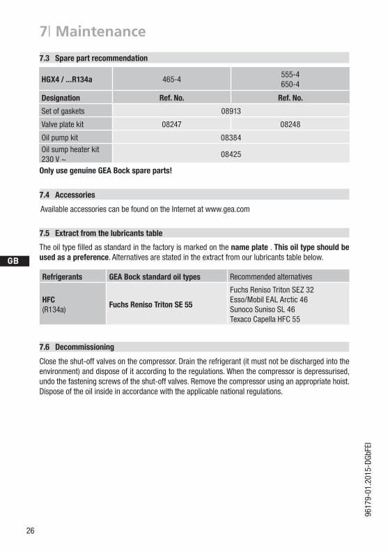
OnlyusegenuineGEABockspareparts!
7.3 Spare part recommendation
HGX4 / ...R134a 465-4555-4650-4
Designation Ref. No. Ref. No.
Set of gaskets 08913
Valveplatekit 08247 08248
Oil pump kit 08384
Oil sump heater kit 230V~
08425
D
GB
F
E
27
9617
9-01
.201
5-DG
bFEI
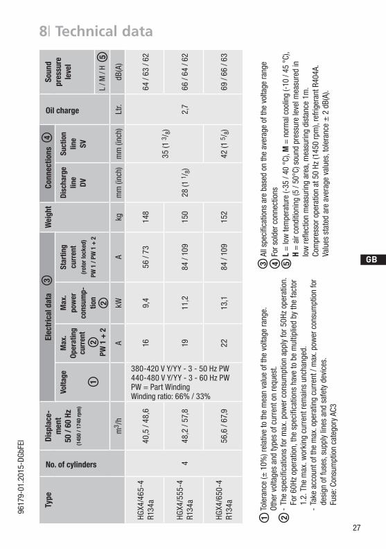
8| Technical data
Tole
ranc
e (±
10%
) rel
ativ
e to
the
mea
n va
lue
of th
e vo
ltage
rang
e.Othe
rvoltage
san
dtype
sofcurrentonrequ
est.
-Th
especifica
tionsfo
rmax
.pow
ercon
sumptionap
plyfor5
0Hzop
eration.
Fo
r60H
zop
eration,th
especifica
tionshavetobemultip
liedbyth
efactor
1.
2. T
he m
ax. w
orki
ng c
urre
nt re
mai
ns u
ncha
nged
.
- Ta
ke a
ccou
nt o
f the
max
. ope
ratin
g cu
rren
t / m
ax. p
ower
con
sum
ptio
n fo
r
desi
gn o
f fus
es, s
uppl
y lin
es a
nd s
afet
y de
vice
s.
Fu
se: C
onsu
mpt
ion
cate
gory
AC3
1 2
Allspe
cific
ationsarebased
ontheaverag
eofth
evolta
gera
nge
For s
olde
r con
nect
ions
L =
low
tem
pera
ture
(-35
/ 40
°C)
, M =
nor
mal
coo
ling
(-10
/ 45
°C)
,H
= a
ir co
nditi
onin
g (5
/ 50
°C) s
ound
pre
ssur
e le
vel m
easu
red
in
lowre
flectionmea
surin
garea
,mea
surin
gdistan
ce1m.
Com
pres
sor o
pera
tion
at 5
0 Hz
(145
0 rp
m),
refri
gera
nt R
404A
.Va
luesstatedareaverag
evalues,toleran
ce±2dB(A).
53 4
Type
No. of cylinders
Disp
lace
-m
ent
50/60Hz
(145
0 / 1
740
rpm
)
Elec
tric
al d
ata
Wei
ght
C
onne
ctio
ns
Oil charge
Soun
d pr
essu
re
leve
lVo
ltage
Max
.Op
erat
ing
curr
ent
PW
1 +
2
Max
. po
wer
co
nsum
p-tio
n
Star
ting
cu
rren
t(rotorlock
ed)
PW 1
/ PW
1 +
2
Disc
harg
elin
e DV
Suct
ion
line
SV
m3 /
hA
kWA
kgm
m (i
nch)
mm
(inc
h)Lt
r.dB
(A)
HGX4
/465
-4
R134
a
4
40,5
/ 48
,616
9,4
56 /
7314
8
28 (1
1/ 8
)
35 (1
3/ 8
)
2,7
64 /
63 /
62
HGX4
/555
-4
R134
a48
,2 /
57,8
1911
,284
/ 10
915
066
/ 64
/ 62
HGX4
/650
-4
R134
a56
,6 /
67,9
2213
,184
/ 10
915
242
(1 5
/ 8)
69 /
66 /
63
12
3
2
4
380-420VY/YY-3-50HzPW440-480VY/YY-3-60HzPWPW = Part WindingWinding ratio: 66% / 33%
L / M
/ H
5
28
D
GB
F
E
9617
9-01
.201
5-DG
bFEI
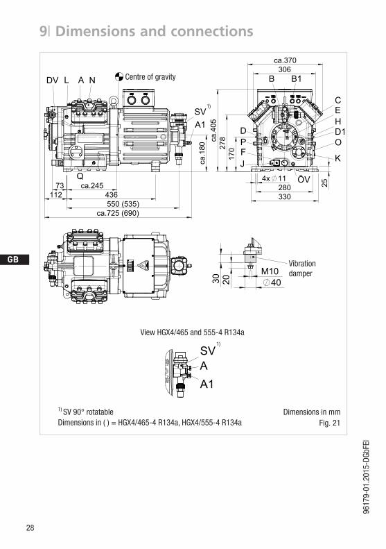
9| Dimensions and connections
Centre of gravity
Ansicht X: Anschlußmöglichkeit für Ölspiegelregulator View X: Possibility of connection of oil level regulator Vue X : Raccord pour régulateur de niveau d’huile
Dreilochanschluß für TRAXOIL (3xM6x10) Three-hole connection for TRAXOIL (3xM6x10) Raccord à trois rainures pour TRAXOIL (3xM6x10)
Dreilochanschluß für ESK, AC+R, CARLY (3xM6x10) Three-hole connection for ESK, AC+R, CARLY (3xM6x10) Raccord à trois rainures pour ESK, AC+R, CARLY (3xM6x10)
ca.245
ca.1
80
ca.370
ca.385
Raccord côté chauffage du carter d’huile
Maße Zubehör / Dimensions Accessories / Dimensions Accessoires
mm M22x1,5
Cotes en mmDimensions in mmMaße in mm
Sous réserve de toutes modifications
Halbhermetischer Verdichter HG / Semi-hermetic compressor HG / Compresseur semi-hermétique HG
1.0850-13764.0 f
Subject to change without noticeÄnderungen vorbehalten
Centre de gravitéCentre of gravityMassenschwerpunkt
K
Côtes en ( ) pour HG(X)4/310-555 -4 (S) Dimensions in ( ) for HG(X)4/310-555 -4 (S)Maße in ( ) für HG(X)4/310-555 -4 (S)
Schauglas Sight glass Voyant - -L
(L)* = Raccord à braser
Anschluß Wärmeschutzthermostat Connection thermal protection thermostat
(L)* = Brazing connection
Raccord de thermostat de protection thermique Zoll
(L)* = Lötanschluß
1/8“ NPTFN Anschluß Leistungsregler Connection capacity controller Raccord régulateur de puissance mm M48x1,5
1/8" NPTF
O Anschluß
Zoll
Ölspiegelregulator Connection oil level regulator
Raccord sonde de température d'huile
Raccord régulateur de niveau d'huile mm 3xM6P Anschluß Öl-Differenzdrucksensor Connection oil pressure differential sensor Raccord sonde de pressostat différentiel d’huile mm M20x1,5
ÖV Anschluß Ölserviceventil Connection oil service valve Raccord vanne de vidange d'huile Zoll 1/4" NPTF
Q Anschluß Öltemperatursensor Connection oil temperature sensor
Anschlüsse Connections Raccords HG4/310-4HG4/385-4
HG4/465-4HG4/555-4 HG4/650-4
SV Saugabsperrventil, Rohr (L)* Suction line valve, tube (L)* Vanne d’arrêt d’aspiration, de tuyau (L)* mm - Zoll 28 -1 1/8“ 35 -1 3/8“ 42 -1 5/8“DV Druckabsperrventil, Rohr (L)* Discharge line valve, tube (L)* Vanne d’arrêt de refoulement, de tuyau (L)* mm - Zoll 22 - 7/8“ 28 -1 1/8“ 28 -1 1/8“A Anschluß Saugseite, nicht absperrbar Connection suction side, not lockable Raccord côté aspiration, non obturable Zoll 1/8“ NPTF
A1 Anschluß Saugseite, absperrbar Connection suction side, lockable Raccord côté aspiration, obturable Zoll 7/16“ UNFB Anschluß Druckseite, nicht absperrbar Connection discharge side, not lockable Raccord côté refoulement, non obturable Zoll 1/8“ NPTF
B1 Anschluß Druckseite, absperrbar Connection discharge side, lockable Raccord côté refoulement, obturable Zoll 7/16“ UNFC Anschluß Öldrucksicherheitsschalter OIL Connection oil pressure safety switch OIL Raccord pressostat de sécurité d'huile OIL Zoll 7/16“ UNFD Anschluß Öldrucksicherheitsschalter LP Connection oil pressure safety switch LP Raccord pressostat de sécurité d'huile LP Zoll 7/16“ UNF
D1 Anschluß Ölrückführung vom Ölabscheider Connection oil return from oil separator Raccord retour d’huile du séparateur d’huile Zoll 1/4“ NPTFE Anschluß Öldruckmanometer Connection oil pressure gauge Raccord du manomètre de pression d’huile Zoll 7/16“ UNFF Ölablaß Oil drain Vidange d’huile mm M22x1,5H Stopfen Ölfüllung Oil charge plug Bouchon de remplissage d’huile mm M22x1,5J Anschluß Ölsumpfheizung Connection oil sump heater
Typ Teile Nr. Typ Teile Nr. Typ Teile Nr. Typ Teile Nr.HG4/310-4 13790* HGX4/310-4 13795* HG4/310-4 S 13760* HGX4/310-4 S 13775*HG4/385-4 13791* HGX4/385-4 13796* HG4/385-4 S 13761* HGX4/385-4 S 13776*HG4/465-4 13792 HGX4/465-4 13797 HG4/465-4 S 13762 HGX4/465-4 S 13777HG4/555-4 13793 HGX4/555-4 13798 HG4/555-4 S 13763 HGX4/555-4 S 13778HG4/650-4 13794 HGX4/650-4 13799 HG4/650-4 S 13764 HGX4/650-4 S 13779* Keine Serie / No series / Pas de séries
schutz, Verpackung für sicheren Transport).
F
E
D
C
B
A
F
E
D
C
4 3 2 1
A
B
5678
12345678
Abnehmer oder Dritte ist nicht gestattet.
Numéro de plan:
Tol.-Ang. DIN ISO 2768-mK
2R
evis
ions
durc
hlau
f:
Pos.504,1086,1087,1088 hinzu., Esterölkleber entf., Gew.stift jetzt Klebst.besch.,Anschlüsse Q u. ÖV eingef.
Ra Rz
U-Scheiben, Pos.181+221, unter Zylinderdeckel und Ventilen eingefügt – Betr. Bl.2+3Maß Passung Freigabe
Alternativbezug:Baumustergeprüft
Teil inaktiv
Lieferantenzeichnung
--
K.-Auftrag:PL:
Zeichnung ungültig
Entwicklungsstand
Teil keine Serie
120400
±0.5
über 0.5bis 6
Benzstraße 7 - 72636 Frickenhausen - Germany - www.bock.de
WidmLayhLayhGörKeu
BüttnerSchniSchni
FrankeWidm
13.01.1013.11.0921.10.0904.12.0818.07.08
763576267609
7341,7368,7417,7431,7437
7307,7283,7285,7342
-----
Betrifft Blatt 2Alle Verdichterbaugrößen von Zeichnung 13762.0c aufgenommenBetrifft Bl.2Massenschwerp. aufgen.;Pos.1089 entfernt,Betr. Bl.2;Stator als BS erhältl.,Zub. aufgen.,Betr. Bl.3
fedcb
-
SchaichBuck07.02.087169-a
-Unbemaßte Radien:
-
Zeichn.-Nr. / Drawing no. /
Wir behalten uns alle Rechte, gemäß DIN ISO 16016
Rz 12,5 Rz 6,3Rz 636,3 Rz 162
an dieser Zeichnung vor.
Bearb.DatumÄnderungs-Nr.
Werkstoff:
Ausgangsteil, bzw. Rohteil:-
-
Gepr.
NameDatum13.07.
09.06.06
WerkstückkantenDIN ISO 13715
Ersatz für:
Ersetzt durch:
Erstellt2005
Geprüft
1.0850-13764.0 z Rev.1
LayhDiegel
Zone
1/3
Oberflächenbehandlung / Härte:-
Blatt:
Änderungsbeschreibung
400Benennung:
±0.8
1000 30 6
-
±0.3
12030
±0.2
Zeichn.-Nr. Teile-Nr.
Oberflächenangaben ISO 1302
1.0850-13764.0
Zust.
Gußtoleranzen:
Gewicht: (kg)
±0.1
Maßstab:
%
HG4/650-4 S
Rz 25Rz 160
s
25
zyxwut
0,05 Rz 1,60,30,71,6
Diese Zeichnung ist unser Eigentum!Sie darf ohne unsere Genehmigung weder nach-gebildet, vervielfältigt, oder Dritten Personen zu-gänglich gemacht werden. Der Nachbau nachdieser Zeichnung, oder an Hand der nach dieserZeichnung hergestellten Gegenstände durch den
Der Lieferant muß sicherstellen, dass die Ware ineinwandfreiem Zustand angeliefert wird (Korrosions-
G:\3
D T
eile
mit
Zeic
hnun
gen\
Zeic
hnun
gen.
DR
W\1
3764
f-1
NDV L
SVA1
A
Q
(535)
73436112550
ca.725 (690)
D
X
EC
JF
HD1O
K
P
B B1
ÖV
ca.4
05
306
28011
330
278
4x
25
170
SchwingungsdämpferVibration absorbersAmortisseurs de vibration
4010M
30 20
ca.6
80
131
416
91
455
ca.
ca.740 (705)
AA1
SV
Ansicht HG(X)4/310-555 -4 (S)View HG(X)4/310-555 -4 (S)Vue HG(X)4/310-555 -4 (S)
Ansicht X: Anschlußmöglichkeit für Ölspiegelregulator View X: Possibility of connection of oil level regulator Vue X : Raccord pour régulateur de niveau d’huile
Dreilochanschluß für TRAXOIL (3xM6x10) Three-hole connection for TRAXOIL (3xM6x10) Raccord à trois rainures pour TRAXOIL (3xM6x10)
Dreilochanschluß für ESK, AC+R, CARLY (3xM6x10) Three-hole connection for ESK, AC+R, CARLY (3xM6x10) Raccord à trois rainures pour ESK, AC+R, CARLY (3xM6x10)
Vibrationdamper
Ansicht X: Anschlußmöglichkeit für Ölspiegelregulator View X: Possibility of connection of oil level regulator Vue X : Raccord pour régulateur de niveau d’huile
Dreilochanschluß für TRAXOIL (3xM6x10) Three-hole connection for TRAXOIL (3xM6x10) Raccord à trois rainures pour TRAXOIL (3xM6x10)
Dreilochanschluß für ESK, AC+R, CARLY (3xM6x10) Three-hole connection for ESK, AC+R, CARLY (3xM6x10) Raccord à trois rainures pour ESK, AC+R, CARLY (3xM6x10)
ca.245ca
.180
ca.370
ca.385
Raccord côté chauffage du carter d’huile
Maße Zubehör / Dimensions Accessories / Dimensions Accessoires
mm M22x1,5
Cotes en mmDimensions in mmMaße in mm
Sous réserve de toutes modifications
Halbhermetischer Verdichter HG / Semi-hermetic compressor HG / Compresseur semi-hermétique HG
1.0850-13764.0 f
Subject to change without noticeÄnderungen vorbehalten
Centre de gravitéCentre of gravityMassenschwerpunkt
K
Côtes en ( ) pour HG(X)4/310-555 -4 (S) Dimensions in ( ) for HG(X)4/310-555 -4 (S)Maße in ( ) für HG(X)4/310-555 -4 (S)
Schauglas Sight glass Voyant - -L
(L)* = Raccord à braser
Anschluß Wärmeschutzthermostat Connection thermal protection thermostat
(L)* = Brazing connection
Raccord de thermostat de protection thermique Zoll
(L)* = Lötanschluß
1/8“ NPTFN Anschluß Leistungsregler Connection capacity controller Raccord régulateur de puissance mm M48x1,5
1/8" NPTF
O Anschluß
Zoll
Ölspiegelregulator Connection oil level regulator
Raccord sonde de température d'huile
Raccord régulateur de niveau d'huile mm 3xM6P Anschluß Öl-Differenzdrucksensor Connection oil pressure differential sensor Raccord sonde de pressostat différentiel d’huile mm M20x1,5
ÖV Anschluß Ölserviceventil Connection oil service valve Raccord vanne de vidange d'huile Zoll 1/4" NPTF
Q Anschluß Öltemperatursensor Connection oil temperature sensor
Anschlüsse Connections Raccords HG4/310-4HG4/385-4
HG4/465-4HG4/555-4 HG4/650-4
SV Saugabsperrventil, Rohr (L)* Suction line valve, tube (L)* Vanne d’arrêt d’aspiration, de tuyau (L)* mm - Zoll 28 -1 1/8“ 35 -1 3/8“ 42 -1 5/8“DV Druckabsperrventil, Rohr (L)* Discharge line valve, tube (L)* Vanne d’arrêt de refoulement, de tuyau (L)* mm - Zoll 22 - 7/8“ 28 -1 1/8“ 28 -1 1/8“A Anschluß Saugseite, nicht absperrbar Connection suction side, not lockable Raccord côté aspiration, non obturable Zoll 1/8“ NPTF
A1 Anschluß Saugseite, absperrbar Connection suction side, lockable Raccord côté aspiration, obturable Zoll 7/16“ UNFB Anschluß Druckseite, nicht absperrbar Connection discharge side, not lockable Raccord côté refoulement, non obturable Zoll 1/8“ NPTF
B1 Anschluß Druckseite, absperrbar Connection discharge side, lockable Raccord côté refoulement, obturable Zoll 7/16“ UNFC Anschluß Öldrucksicherheitsschalter OIL Connection oil pressure safety switch OIL Raccord pressostat de sécurité d'huile OIL Zoll 7/16“ UNFD Anschluß Öldrucksicherheitsschalter LP Connection oil pressure safety switch LP Raccord pressostat de sécurité d'huile LP Zoll 7/16“ UNF
D1 Anschluß Ölrückführung vom Ölabscheider Connection oil return from oil separator Raccord retour d’huile du séparateur d’huile Zoll 1/4“ NPTFE Anschluß Öldruckmanometer Connection oil pressure gauge Raccord du manomètre de pression d’huile Zoll 7/16“ UNFF Ölablaß Oil drain Vidange d’huile mm M22x1,5H Stopfen Ölfüllung Oil charge plug Bouchon de remplissage d’huile mm M22x1,5J Anschluß Ölsumpfheizung Connection oil sump heater
Typ Teile Nr. Typ Teile Nr. Typ Teile Nr. Typ Teile Nr.HG4/310-4 13790* HGX4/310-4 13795* HG4/310-4 S 13760* HGX4/310-4 S 13775*HG4/385-4 13791* HGX4/385-4 13796* HG4/385-4 S 13761* HGX4/385-4 S 13776*HG4/465-4 13792 HGX4/465-4 13797 HG4/465-4 S 13762 HGX4/465-4 S 13777HG4/555-4 13793 HGX4/555-4 13798 HG4/555-4 S 13763 HGX4/555-4 S 13778HG4/650-4 13794 HGX4/650-4 13799 HG4/650-4 S 13764 HGX4/650-4 S 13779* Keine Serie / No series / Pas de séries
schutz, Verpackung für sicheren Transport).
F
E
D
C
B
A
F
E
D
C
4 3 2 1
A
B
5678
12345678
Abnehmer oder Dritte ist nicht gestattet.
Numéro de plan:
Tol.-Ang. DIN ISO 2768-mK
2R
evis
ions
durc
hlau
f:
Pos.504,1086,1087,1088 hinzu., Esterölkleber entf., Gew.stift jetzt Klebst.besch.,Anschlüsse Q u. ÖV eingef.
Ra Rz
U-Scheiben, Pos.181+221, unter Zylinderdeckel und Ventilen eingefügt – Betr. Bl.2+3Maß Passung Freigabe
Alternativbezug:Baumustergeprüft
Teil inaktiv
Lieferantenzeichnung
--
K.-Auftrag:PL:
Zeichnung ungültig
Entwicklungsstand
Teil keine Serie
120400
±0.5
über 0.5bis 6
Benzstraße 7 - 72636 Frickenhausen - Germany - www.bock.de
WidmLayhLayhGörKeu
BüttnerSchniSchni
FrankeWidm
13.01.1013.11.0921.10.0904.12.0818.07.08
763576267609
7341,7368,7417,7431,7437
7307,7283,7285,7342
-----
Betrifft Blatt 2Alle Verdichterbaugrößen von Zeichnung 13762.0c aufgenommenBetrifft Bl.2Massenschwerp. aufgen.;Pos.1089 entfernt,Betr. Bl.2;Stator als BS erhältl.,Zub. aufgen.,Betr. Bl.3
fedcb
-
SchaichBuck07.02.087169-a
-Unbemaßte Radien:
-
Zeichn.-Nr. / Drawing no. /
Wir behalten uns alle Rechte, gemäß DIN ISO 16016
Rz 12,5 Rz 6,3Rz 636,3 Rz 162
an dieser Zeichnung vor.
Bearb.DatumÄnderungs-Nr.
Werkstoff:
Ausgangsteil, bzw. Rohteil:-
-
Gepr.
NameDatum13.07.
09.06.06
WerkstückkantenDIN ISO 13715
Ersatz für:
Ersetzt durch:
Erstellt2005
Geprüft
1.0850-13764.0 z Rev.1
LayhDiegel
Zone
1/3
Oberflächenbehandlung / Härte:-
Blatt:
Änderungsbeschreibung
400Benennung:
±0.8
1000 30 6
-
±0.3
12030
±0.2
Zeichn.-Nr. Teile-Nr.
Oberflächenangaben ISO 1302
1.0850-13764.0
Zust.
Gußtoleranzen:
Gewicht: (kg)
±0.1
Maßstab:
%
HG4/650-4 S
Rz 25Rz 160
s
25
zyxwut
0,05 Rz 1,60,30,71,6
Diese Zeichnung ist unser Eigentum!Sie darf ohne unsere Genehmigung weder nach-gebildet, vervielfältigt, oder Dritten Personen zu-gänglich gemacht werden. Der Nachbau nachdieser Zeichnung, oder an Hand der nach dieserZeichnung hergestellten Gegenstände durch den
Der Lieferant muß sicherstellen, dass die Ware ineinwandfreiem Zustand angeliefert wird (Korrosions-
G:\3
D T
eile
mit
Zeic
hnun
gen\
Zeic
hnun
gen.
DR
W\1
3764
f-1
NDV L
SVA1
A
Q
(535)
73436112550
ca.725 (690)
D
X
EC
JF
HD1O
K
P
B B1
ÖVca
.405
306
28011
33027
8
4x
25
170
SchwingungsdämpferVibration absorbersAmortisseurs de vibration
4010M
30 20
ca.6
80
131
416
91
455
ca.
ca.740 (705)
AA1
SV
Ansicht HG(X)4/310-555 -4 (S)View HG(X)4/310-555 -4 (S)Vue HG(X)4/310-555 -4 (S)
Ansicht X: Anschlußmöglichkeit für Ölspiegelregulator View X: Possibility of connection of oil level regulator Vue X : Raccord pour régulateur de niveau d’huile
Dreilochanschluß für TRAXOIL (3xM6x10) Three-hole connection for TRAXOIL (3xM6x10) Raccord à trois rainures pour TRAXOIL (3xM6x10)
Dreilochanschluß für ESK, AC+R, CARLY (3xM6x10) Three-hole connection for ESK, AC+R, CARLY (3xM6x10) Raccord à trois rainures pour ESK, AC+R, CARLY (3xM6x10)
1)
Fig. 21Dimensions in mm1)
SV90°rotatable
Ansicht X: Anschlußmöglichkeit für Ölspiegelregulator View X: Possibility of connection of oil level regulator Vue X : Raccord pour régulateur de niveau d’huile
Dreilochanschluß für TRAXOIL (3xM6x10) Three-hole connection for TRAXOIL (3xM6x10) Raccord à trois rainures pour TRAXOIL (3xM6x10)
Dreilochanschluß für ESK, AC+R, CARLY (3xM6x10) Three-hole connection for ESK, AC+R, CARLY (3xM6x10) Raccord à trois rainures pour ESK, AC+R, CARLY (3xM6x10)
ca.245
ca.1
80
ca.370
ca.385
Raccord côté chauffage du carter d’huile
Maße Zubehör / Dimensions Accessories / Dimensions Accessoires
mm M22x1,5
Cotes en mmDimensions in mmMaße in mm
Sous réserve de toutes modifications
Halbhermetischer Verdichter HG / Semi-hermetic compressor HG / Compresseur semi-hermétique HG
1.0850-13764.0 f
Subject to change without noticeÄnderungen vorbehalten
Centre de gravitéCentre of gravityMassenschwerpunkt
K
Côtes en ( ) pour HG(X)4/310-555 -4 (S) Dimensions in ( ) for HG(X)4/310-555 -4 (S)Maße in ( ) für HG(X)4/310-555 -4 (S)
Schauglas Sight glass Voyant - -L
(L)* = Raccord à braser
Anschluß Wärmeschutzthermostat Connection thermal protection thermostat
(L)* = Brazing connection
Raccord de thermostat de protection thermique Zoll
(L)* = Lötanschluß
1/8“ NPTFN Anschluß Leistungsregler Connection capacity controller Raccord régulateur de puissance mm M48x1,5
1/8" NPTF
O Anschluß
Zoll
Ölspiegelregulator Connection oil level regulator
Raccord sonde de température d'huile
Raccord régulateur de niveau d'huile mm 3xM6P Anschluß Öl-Differenzdrucksensor Connection oil pressure differential sensor Raccord sonde de pressostat différentiel d’huile mm M20x1,5
ÖV Anschluß Ölserviceventil Connection oil service valve Raccord vanne de vidange d'huile Zoll 1/4" NPTF
Q Anschluß Öltemperatursensor Connection oil temperature sensor
Anschlüsse Connections Raccords HG4/310-4HG4/385-4
HG4/465-4HG4/555-4 HG4/650-4
SV Saugabsperrventil, Rohr (L)* Suction line valve, tube (L)* Vanne d’arrêt d’aspiration, de tuyau (L)* mm - Zoll 28 -1 1/8“ 35 -1 3/8“ 42 -1 5/8“DV Druckabsperrventil, Rohr (L)* Discharge line valve, tube (L)* Vanne d’arrêt de refoulement, de tuyau (L)* mm - Zoll 22 - 7/8“ 28 -1 1/8“ 28 -1 1/8“A Anschluß Saugseite, nicht absperrbar Connection suction side, not lockable Raccord côté aspiration, non obturable Zoll 1/8“ NPTF
A1 Anschluß Saugseite, absperrbar Connection suction side, lockable Raccord côté aspiration, obturable Zoll 7/16“ UNFB Anschluß Druckseite, nicht absperrbar Connection discharge side, not lockable Raccord côté refoulement, non obturable Zoll 1/8“ NPTF
B1 Anschluß Druckseite, absperrbar Connection discharge side, lockable Raccord côté refoulement, obturable Zoll 7/16“ UNFC Anschluß Öldrucksicherheitsschalter OIL Connection oil pressure safety switch OIL Raccord pressostat de sécurité d'huile OIL Zoll 7/16“ UNFD Anschluß Öldrucksicherheitsschalter LP Connection oil pressure safety switch LP Raccord pressostat de sécurité d'huile LP Zoll 7/16“ UNF
D1 Anschluß Ölrückführung vom Ölabscheider Connection oil return from oil separator Raccord retour d’huile du séparateur d’huile Zoll 1/4“ NPTFE Anschluß Öldruckmanometer Connection oil pressure gauge Raccord du manomètre de pression d’huile Zoll 7/16“ UNFF Ölablaß Oil drain Vidange d’huile mm M22x1,5H Stopfen Ölfüllung Oil charge plug Bouchon de remplissage d’huile mm M22x1,5J Anschluß Ölsumpfheizung Connection oil sump heater
Typ Teile Nr. Typ Teile Nr. Typ Teile Nr. Typ Teile Nr.HG4/310-4 13790* HGX4/310-4 13795* HG4/310-4 S 13760* HGX4/310-4 S 13775*HG4/385-4 13791* HGX4/385-4 13796* HG4/385-4 S 13761* HGX4/385-4 S 13776*HG4/465-4 13792 HGX4/465-4 13797 HG4/465-4 S 13762 HGX4/465-4 S 13777HG4/555-4 13793 HGX4/555-4 13798 HG4/555-4 S 13763 HGX4/555-4 S 13778HG4/650-4 13794 HGX4/650-4 13799 HG4/650-4 S 13764 HGX4/650-4 S 13779* Keine Serie / No series / Pas de séries
schutz, Verpackung für sicheren Transport).
F
E
D
C
B
A
F
E
D
C
4 3 2 1
A
B
5678
12345678
Abnehmer oder Dritte ist nicht gestattet.
Numéro de plan:
Tol.-Ang. DIN ISO 2768-mK
2R
evis
ions
durc
hlau
f:
Pos.504,1086,1087,1088 hinzu., Esterölkleber entf., Gew.stift jetzt Klebst.besch.,Anschlüsse Q u. ÖV eingef.
Ra Rz
U-Scheiben, Pos.181+221, unter Zylinderdeckel und Ventilen eingefügt – Betr. Bl.2+3Maß Passung Freigabe
Alternativbezug:Baumustergeprüft
Teil inaktiv
Lieferantenzeichnung
--
K.-Auftrag:PL:
Zeichnung ungültig
Entwicklungsstand
Teil keine Serie
120400
±0.5
über 0.5bis 6
Benzstraße 7 - 72636 Frickenhausen - Germany - www.bock.de
WidmLayhLayhGörKeu
BüttnerSchniSchni
FrankeWidm
13.01.1013.11.0921.10.0904.12.0818.07.08
763576267609
7341,7368,7417,7431,7437
7307,7283,7285,7342
-----
Betrifft Blatt 2Alle Verdichterbaugrößen von Zeichnung 13762.0c aufgenommenBetrifft Bl.2Massenschwerp. aufgen.;Pos.1089 entfernt,Betr. Bl.2;Stator als BS erhältl.,Zub. aufgen.,Betr. Bl.3
fedcb
-
SchaichBuck07.02.087169-a
-Unbemaßte Radien:
-
Zeichn.-Nr. / Drawing no. /
Wir behalten uns alle Rechte, gemäß DIN ISO 16016
Rz 12,5 Rz 6,3Rz 636,3 Rz 162
an dieser Zeichnung vor.
Bearb.DatumÄnderungs-Nr.
Werkstoff:
Ausgangsteil, bzw. Rohteil:-
-
Gepr.
NameDatum13.07.
09.06.06
WerkstückkantenDIN ISO 13715
Ersatz für:
Ersetzt durch:
Erstellt2005
Geprüft
1.0850-13764.0 z Rev.1
LayhDiegel
Zone
1/3
Oberflächenbehandlung / Härte:-
Blatt:
Änderungsbeschreibung
400Benennung:
±0.8
1000 30 6
-
±0.3
12030
±0.2
Zeichn.-Nr. Teile-Nr.
Oberflächenangaben ISO 1302
1.0850-13764.0
Zust.
Gußtoleranzen:
Gewicht: (kg)
±0.1
Maßstab:
%
HG4/650-4 S
Rz 25Rz 160
s
25
zyxwut
0,05 Rz 1,60,30,71,6
Diese Zeichnung ist unser Eigentum!Sie darf ohne unsere Genehmigung weder nach-gebildet, vervielfältigt, oder Dritten Personen zu-gänglich gemacht werden. Der Nachbau nachdieser Zeichnung, oder an Hand der nach dieserZeichnung hergestellten Gegenstände durch den
Der Lieferant muß sicherstellen, dass die Ware ineinwandfreiem Zustand angeliefert wird (Korrosions-
G:\3
D T
eile
mit
Zeic
hnun
gen\
Zeic
hnun
gen.
DR
W\1
3764
f-1
NDV L
SVA1
A
Q
(535)
73436112550
ca.725 (690)
D
X
EC
JF
HD1O
K
P
B B1
ÖV
ca.4
05
306
28011
330
278
4x
25
170
SchwingungsdämpferVibration absorbersAmortisseurs de vibration
4010M
30 20
ca.6
80
131
416
91
455
ca.
ca.740 (705)
AA1
SV
Ansicht HG(X)4/310-555 -4 (S)View HG(X)4/310-555 -4 (S)Vue HG(X)4/310-555 -4 (S)
Ansicht X: Anschlußmöglichkeit für Ölspiegelregulator View X: Possibility of connection of oil level regulator Vue X : Raccord pour régulateur de niveau d’huile
Dreilochanschluß für TRAXOIL (3xM6x10) Three-hole connection for TRAXOIL (3xM6x10) Raccord à trois rainures pour TRAXOIL (3xM6x10)
Dreilochanschluß für ESK, AC+R, CARLY (3xM6x10) Three-hole connection for ESK, AC+R, CARLY (3xM6x10) Raccord à trois rainures pour ESK, AC+R, CARLY (3xM6x10)
ViewHGX4/465and555-4R134a1)
Dimensions in ( ) = HGX4/465-4 R134a, HGX4/555-4 R134a
D
GB
F
E
29
9617
9-01
.201
5-DG
bFEI
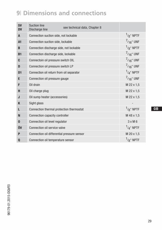
9| Dimensions and connections
SVDV
Suction lineDischarge line see technical data, Chapter 8
A Connection suction side, not lockable 1/8“ NPTF
A1 Connection suction side, lockable 7/16“ UNF
B Connection discharge side, not lockable 1/8“ NPTF
B1 Connection discharge side, lockable 7/16“ UNF
C Connectoin oil pressure switch OIL 7/16“ UNF
D Connection oil pressure switch LP 7/16“ UNF
D1 Connection oil return from oil separator 1/4“ NPTF
E Connection oil pressure gauge 7/16“ UNF
F Oil drain M 22 x 1,5
H Oil charge plug M 22 x 1,5
J Oil sump heater (accessories) M 22 x 1,5
K Sight glass -
L Connection thermal protection thermostat 1/8“ NPTF
N Connection capacity controller M 48 x 1,5
O Connection oil level regulator 3 x M 6
ÖV Connection oil service valve 1/4“ NPTF
P Connection oil differential pressure sensor M 20 x 1,5
Q Connection oil temperature sensor 1/8“ NPTF
30
D
GB
F
E
9617
9-01
.201
5-DG
bFEI
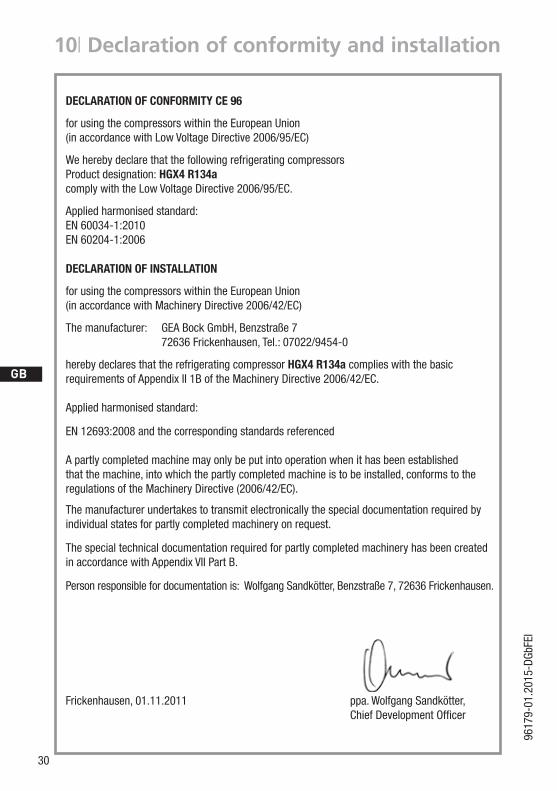
10| Declaration of conformity and installation
DECLARATION OF CONFORMITY CE 96
for using the compressors within the European Union(inaccordancewithLowVoltageDirective2006/95/EC)
We hereby declare that the following refrigerating compressorsProduct designation: HGX4 R134acomplywiththeLowVoltageDirective2006/95/EC.
Applied harmonised standard: EN 60034-1:2010 EN 60204-1:2006
DECLARATION OF INSTALLATION
for using the compressors within the European Union(in accordance with Machinery Directive 2006/42/EC)
The manufacturer: GEA Bock GmbH, Benzstraße 7 72636 Frickenhausen, Tel.: 07022/9454-0
hereby declares that the refrigerating compressor HGX4 R134a complies with the basic requirementsofAppendixII1BoftheMachineryDirective2006/42/EC. Applied harmonised standard:
EN 12693:2008 and the corresponding standards referenced
A partly completed machine may only be put into operation when it has been established that the machine, into which the partly completed machine is to be installed, conforms to the regulations of the Machinery Directive (2006/42/EC).
Themanufacturerundertakestotransmitelectronicallythespecialdocumentationrequiredbyindividualstatesforpartlycompletedmachineryonrequest.
ThespecialtechnicaldocumentationrequiredforpartlycompletedmachineryhasbeencreatedinaccordancewithAppendixVIIPartB.
Person responsible for documentation is: Wolfgang Sandkötter, Benzstraße 7, 72636 Frickenhausen.
Frickenhausen, 01.11.2011 ppa. Wolfgang Sandkötter, ChiefDevelopmentOfficer
D
GB
F
E
31
9617
9-01
.201
5-DG
bFEI
Dear customer,
GEABockcompressorsaretop-quality,reliableandservice-friendlyqualityproducts. Ifyouhaveanyquestionsaboutinstallation,operationandaccessories,pleasecontactourtechni-cal service or specialist wholesaler and/or our representative. The GEA Bock service team can be contacted by phone with a toll-free hotline 00 800 / 800 000 88 or via e-mail: [email protected]
Yours faithfully
GEABockGmbH
Benzstraße7
72636Frickenhausen
Germany
11| Service

32
D
GB
F
E
9617
9-01
.201
5-DG
bFEI
9617
9-01
.201
5-D
GbF
EI ©
GEA
Gro
up A
G. A
ll rig
hts
rese
rved
.
GEA Refrigeration TechnologiesGEA Bock GmbH
Benzstraße 7, 72636 Frickenhausen, GermanyTelephone: +49 7022 9454-0, Fax: +49 7022 [email protected], www.gea.com
We live our values.Excellence • Passion • Integrity • Responsibility • GEA-versity
GEA Group is a global engineering company with multi-billion euro sales and operations in more than 50 countries. Founded in 1881, the company is one of the largest providers of innovative equipment and process technology. GEA Group is listed in the STOXX® Europe 600 index.