Embed Size (px)
Citation preview

Uppgjord/Prepared MG
Godkänd/Approved JoRu
Datum/Date 201217
Ritning Nr./Drawing No. 101519 eng
Page 1(28) ver. 7
Mailing address: Website Telephone Scanmast AB www.scanmast.se +46 250 292 00 Box 121 FAX: SE-792 22 Mora +46 250 140 78
Assembly instruction
Tower ALTA
This assembly instruction has been drawn up in accordance with SS-EN 1090-2 and should be used as guidance for trained installers with expertise in the field of erecting masts and towers. Scanmast AB reserves the right to make changes, revise and interpret this instruction.
Datum/Date 201217
Ritning Nr./Drawing No. 101519 eng
Page 2(28) ver. 7
CONTENTS:
1. CASTING FOUNDATION BOLTS IN TOWER FOUNDATION .............................. 3 1.1 Section 11-14 .............................................................................................. 3 1.2 Section 15-17 .............................................................................................. 4
1.3 Section 18 ................................................................................................... 5 1.4 Section 19 ................................................................................................... 6 1.5 Section 20 ................................................................................................... 7
2 ASSEMBLING SECTIONS ..................................................................................... 8 2.1 Fully welded sections 20 and 19 ............................................................... 9
2.2 Section 193, 18/183 ................................................................................... 10 2.3 Section 17/171........................................................................................... 11 2.5 Section 15/151........................................................................................... 13
2.6 Section 14/141........................................................................................... 14 2.7 Section 13/131, 12/121, 11/111 ................................................................. 15
3 ASSEMBLING PARTS.......................................................................................... 16 3.1 Section joint .............................................................................................. 16
3.2 Ladder bracket 707929 ............................................................................. 18
3.3 Ladder bracket 707930 ............................................................................. 19 3.4 Cover plate section 20 ............................................................................. 20 3.5 Ladder joint ............................................................................................... 20
4 ERECTING THE TOWER ...................................................................................... 21 4.1 Erecting tower having completely assembled it on the ground ........... 21
4.2 Joints between base plates and section 11-17 ...................................... 22 5. UNDER CASTING BASE PLATES ...................................................................... 23
5.1 Warranty conditions .................................................................................. 23
5.2 Section 11-17 ............................................................................................ 23 5.3 Section 18-19 ............................................................................................ 23
5.4 Section 20 ................................................................................................. 23 6. SPECIFICATIONS ............................................................................................... 24
6.1 Torque for tightening screw joints (Does not apply to flange joints between sections!) .......................................................................................... 24 6.2 Torque for tightening foundation bolts .................................................. 24 6.3 Locking with punch mark ........................................................................ 24
6.4 Weight specifications ............................................................................... 25 7. PROPOSAL FOR INSPECTION PLAN ............................................................... 26 8. OPERATION AND MAINTENANCE .................................................................... 27
8.1 Operation ................................................................................................... 27
8.2 Maintenance ............................................................................................... 27 10. RISK AREA ........................................................................................................ 28
Datum/Date 201217
Ritning Nr./Drawing No. 101519 eng
Page 3(28) ver. 7
L
L
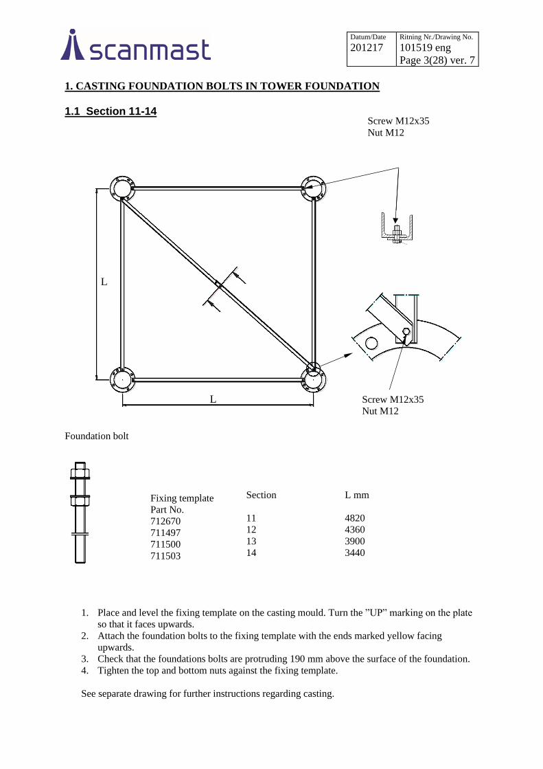
1. CASTING FOUNDATION BOLTS IN TOWER FOUNDATION
1.1 Section 11-14
Foundation bolt
Fixing template
Part No.
712670
711497
711500
711503
Section
11
12
13
14
L mm
4820
4360
3900
3440
1. Place and level the fixing template on the casting mould. Turn the ”UP” marking on the plate
so that it faces upwards.
2. Attach the foundation bolts to the fixing template with the ends marked yellow facing
upwards.
3. Check that the foundations bolts are protruding 190 mm above the surface of the foundation.
4. Tighten the top and bottom nuts against the fixing template.
See separate drawing for further instructions regarding casting.
Screw M12x35
Nut M12
Screw M12x35
Nut M12

Datum/Date 201217
Ritning Nr./Drawing No. 101519 eng
Page 4(28) ver. 7
1.2 Section 15-17
Foundation bolt
Fixing
template
Part No.
711514
715700
715701
Section
15
16
17
L mm
2980
2520
2060
1. Place and level the fixing template on the casting mould. Turn the ”UP” marking on the plate
so that it faces upwards.
2. Attach the foundation bolts to the fixing template with the ends marked yellow facing
upwards.
3. Check that the foundation bolts are protruding 190 mm above the surface of the foundation.
4. Tighten the top and bottom nuts against the fixing template.
See separate drawing for further instructions regarding casting.
Datum/Date 201217
Ritning Nr./Drawing No. 101519 eng
Page 5(28) ver. 7
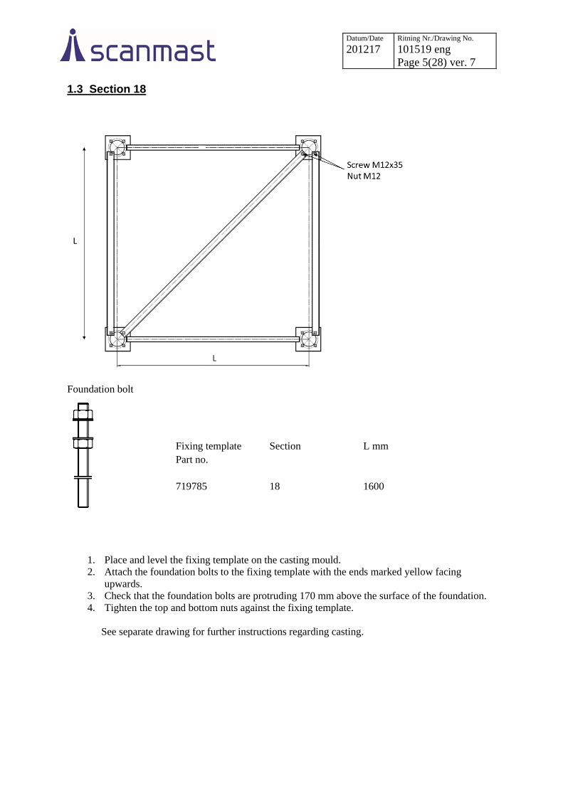
1.3 Section 18
Foundation bolt
1. Place and level the fixing template on the casting mould.
2. Attach the foundation bolts to the fixing template with the ends marked yellow facing
upwards.
3. Check that the foundation bolts are protruding 170 mm above the surface of the foundation.
4. Tighten the top and bottom nuts against the fixing template.
See separate drawing for further instructions regarding casting.
Fixing template Section L mm
Part no.
719785 18 1600
Datum/Date 201217
Ritning Nr./Drawing No. 101519 eng
Page 6(28) ver. 7
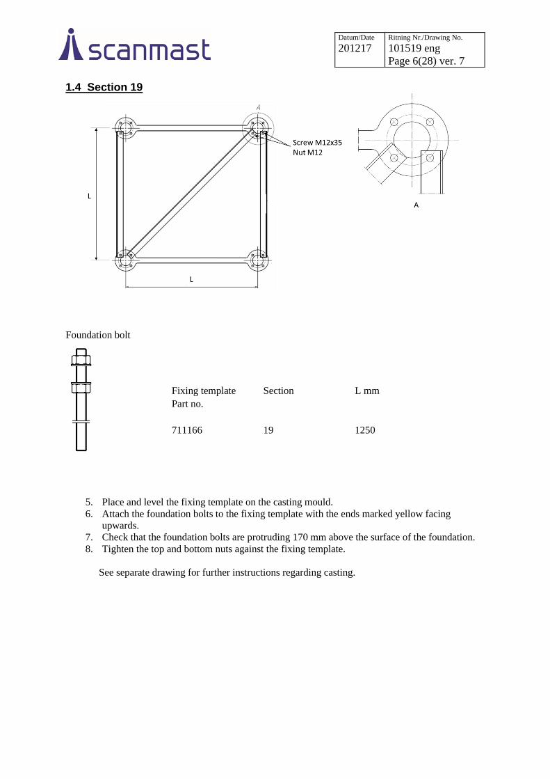
1.4 Section 19
Foundation bolt
5. Place and level the fixing template on the casting mould.
6. Attach the foundation bolts to the fixing template with the ends marked yellow facing
upwards.
7. Check that the foundation bolts are protruding 170 mm above the surface of the foundation.
8. Tighten the top and bottom nuts against the fixing template.
See separate drawing for further instructions regarding casting.
Fixing template Section L mm
Part no.
711166 19 1250
Datum/Date 201217
Ritning Nr./Drawing No. 101519 eng
Page 7(28) ver. 7
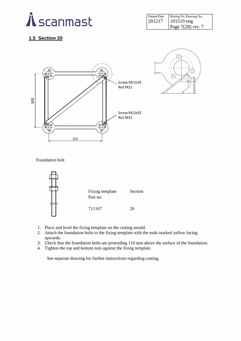
1.5 Section 20
Foundation bolt
1. Place and level the fixing template on the casting mould.
2. Attach the foundation bolts to the fixing template with the ends marked yellow facing
upwards.
3. Check that the foundation bolts are protruding 110 mm above the surface of the foundation.
4. Tighten the top and bottom nuts against the fixing template.
See separate drawing for further instructions regarding casting.
Fixing template Section
Part no.
711167 20

Datum/Date 201217
Ritning Nr./Drawing No. 101519 eng
Page 8(28) ver. 7
2 ASSEMBLING SECTIONS The easiest way to erect the tower is with a mobile crane once it is fully assembled horizontally on the
ground. These instructions assume that sections 19 and 20 are welded and that other sections are
assembled on site. The supports should be levelled to avoid the tower twisting.
General procedure (assembly instructions for each section are set out in the following pages)
1. Assemble the welded sections.
2. Fit the lower two legs for section 18 to the bottom of section 19.
3. Fit the diagonal which is closest to the higher section which is already completed and proceed
with the diagonals ”downwards”. Create a ”floor” in this way.
4. Assemble the two remaining legs with diagonals in the same way on their own supports.
5. Having completed the unit consisting of 2 legs with intermediate diagonals, lift it into position
and connect together with section 19.
6. Fit the diagonals in the two remaining sides of the section starting from the top end of the
section.
7. Tighten the screw joints for the diagonals with torque. Tighten the screw joints in the section
joints with torque and tighten angles according to instructions on pages 15-16.
8. Repeat the above procedure section by section down the tower.
9. Leave the final diagonals closest to the foundation undone until the tower has been placed on
the foundation.
Marking
The undersides of the bottom joining flanges on the legs are marked with section numbers. The
diagonals are numbered and the marking should be facing upwards.
Support

Datum/Date 201217
Ritning Nr./Drawing No. 101519 eng
Page 9(28) ver. 7
2.1 Fully welded sections 20 and 19 The fully welded sections shall have the marking on the underside of the joining flanges facing
downwards. The direction of the bottom diagonal is then obliquely up to the right (when viewed from
the outside of the section).
Assembly instruction for ladder page 17.
1250
900
900
Datum/Date 201217
Ritning Nr./Drawing No. 101519 eng
Page 10(28) ver. 7
1250
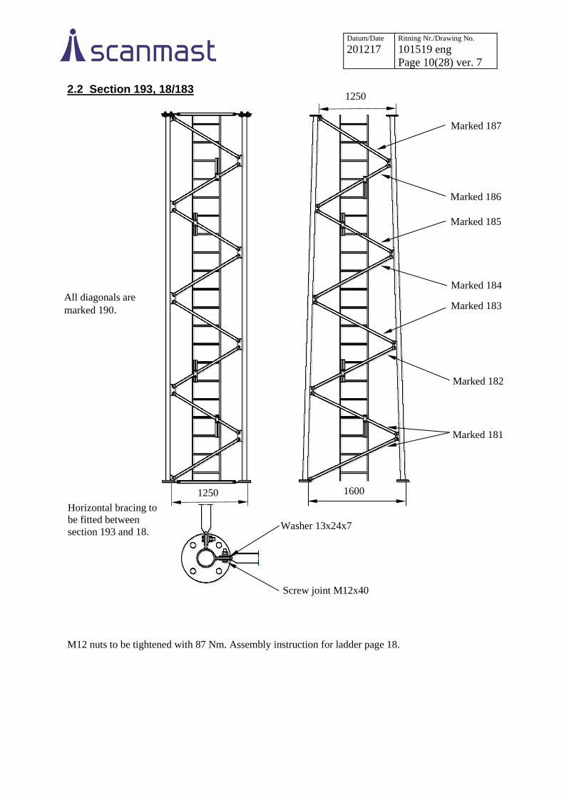
2.2 Section 193, 18/183
M12 nuts to be tightened with 87 Nm. Assembly instruction for ladder page 18.
Horizontal bracing to
be fitted between
section 193 and 18. Washer 13x24x7
Screw joint M12x40
All diagonals are
marked 190.
Marked 181
Marked 182
Marked 183
Marked 184
Marked 185
Marked 186
Marked 187
1600
1250

Datum/Date 201217
Ritning Nr./Drawing No. 101519 eng
Page 11(28) ver. 7
2.3 Section 17/171 Horizontal bracing to be fitted between section 17 and 18.
Note that the diagonal in the bottom left corner must be placed to the outside of the diagonal lug, and
that the diagonal screws at the very bottom of the section are to be turned the opposite way to the
others so that there is access to tighten the flange joints, and that spacer 101082 replaces the washers
there. Nuts M10 are tightened with 50 Nm, M12 with 87 Nm. Assembly instruction for ladder page 17-18.
Marked
174/174F
Marked
172/172F
Spacer
Washer 13x24x7
Between diagonals Screw M10x90
Washer 10.5x20x2 Nut M10
Marked
171/171F
Marked
173/773F
Washer 13x24x7
Between diagonals
Washer 10.5x20x2
Nut M10
Screw M10x30
Screw joint M12x35
Washer 13x24x7
1600
2060
Diagonal cross, section 171
Diagonal cross, section 17
Section 171 Screw joint M12x35
Washer 13x24x7
Section 17 Screw joint M12x55
Spacer
B-B

Datum/Date 201217
Ritning Nr./Drawing No. 101519 eng
Page 12(28) ver. 7
2.4 Section 16/161
Note that the diagonal in the bottom left corner shall be placed to the outside of the diagonal lug, and
that the diagonal screws at the very bottom and very top of the section are to be turned the opposite
way to the others so that there is access to tighten the flange joints, and that spacer 101082 replaces the
washers there.
Nuts M10 are tightened with 50 Nm, M12 with 87 Nm. Assembly instruction for ladder page 17-18.
Washer 10.5x20x2
Spacer
Diagonal cross, section 16
Nut M10
Washer 13x24x7
Between diagonals
Screw M10x90
Washer 13x24x7
Between diagonals
Screw M10x30
Washer 10.5x20x2 Nut M10
Screw joint M12x35
Washer 13x24x7
Diagonal cross, section 161 Marked
164/164F
Marked
163/163F
Marked
162/162F
Marked
161/161F
2060
2520
Section 161 Screw joint M12x35
Washer 13x24x7
Section 16 Screw joint M12x55
Spacer
A-A
B-B

Datum/Date 201217
Ritning Nr./Drawing No. 101519 eng
Page 13(28) ver. 7
2.5 Section 15/151
Note that the diagonal in the bottom left corner shall be placed on the inside of the lug, in distinction
from the other sections, and that the diagonal screws at the bottom of the section are to be turned the
opposite way to the others so that there is access to tighten the flange joints.
M12 nuts to be tightened with 87 Nm. Assembly instruction for ladder page 18.
2520
2980
Washer 13x24x7
Screw joint M12x35
Marked
153/153F
Marked
152/152F
Marked
151/151F
Screw joint M12x35
Washer 13x24x7
Washer 13x24x7
Between diagonals
Screw joint M12x35
Washer 13x24x7
B-B
A-A
Datum/Date 201217
Ritning Nr./Drawing No. 101519 eng
Page 14(28) ver. 7
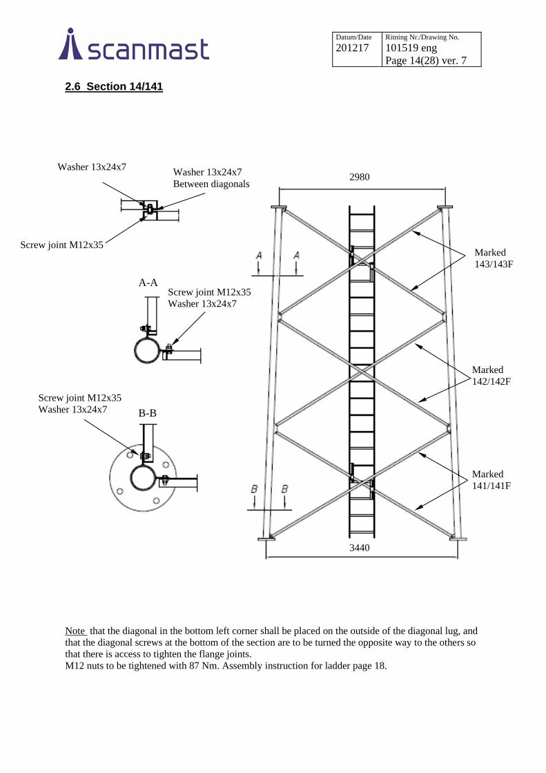
2.6 Section 14/141
Note that the diagonal in the bottom left corner shall be placed on the outside of the diagonal lug, and
that the diagonal screws at the bottom of the section are to be turned the opposite way to the others so
that there is access to tighten the flange joints.
M12 nuts to be tightened with 87 Nm. Assembly instruction for ladder page 18.
Washer 13x24x7
Screw joint M12x35
Screw joint M12x35
Washer 13x24x7
Marked
143/143F
Marked
142/142F
Marked
141/141F
3440
2980 Washer 13x24x7
Between diagonals
Screw joint M12x35
Washer 13x24x7
A-A
B-B

Datum/Date 201217
Ritning Nr./Drawing No. 101519 eng
Page 15(28) ver. 7
2.7 Section 13/131, 12/121, 11/111
The sections 11/111, 12/121 and 13/131 should be stabilised diagonally using, for example, lashing
straps, to avoid handling damage during assembly/lifting.
L1 mm L2 mm D1 marking D2 marking
Section 13/131 3440 3900 131 132
Section 12/121 3900 4360 121 122
Section 11/111 4360 4820 111 112
Note that the diagonal in the bottom left corner shall be placed on the outside of the diagonal lug, and
that the diagonal screws at the bottom of the section are to be turned the opposite way to the others so
that there is access to tighten the flange joints.
M12 nuts to be tightened with 211 Nm. Assembly instruction for ladder page 18.
Screw joint M16x40
Washer 17x30x7
Screw joint
M16x40
Washer 17x30x7
L2
L1
D1
D2
Washer 17x30x7
Between diagonals
Screw joint M16x40
Washer 17x30x7
B-B
A-A

Datum/Date 201217
Ritning Nr./Drawing No. 101519 eng
Page 16(28) ver. 7
3 ASSEMBLING PARTS
3.1 Section joint
Tightening method HR assembly according to SS-EN 1090-2 The flange joints have a different type of screw joint and tightening method than the other joints. The
screw joint has a tested friction between screw and nut and must not be further lubricated.
It is important to remember to keep the screw joint in its bag for as long as possible in order to avoid
the lubricant being washed away by rain etc.
When tightening, first tighten all nuts in the joint to the torque indicated in the table.
Joint Screw joint Part No. Tightening torque
11-12 HR 24x110 8.8/8 galvanized 100862 446 Nm
12-13 HR 24x110 8.8/8 galvanized 100862 446 Nm
13-14 HR 24x110 8.8/8 galvanized 100862 446 Nm
14-15 HR 22x100 8.8/8 galvanized 100867 351 Nm
15-16 HR 22x100 8.8/8 galvanized 100867 351 Nm
16-17 HR 20x 90 8.8/8 galvanized 100871 258 Nm
17-18 HR 20x 90 8.8/8 galvanized 100871 258 Nm
18-19 HR 20x 80 8.8/8 galvanized 100875 258 Nm
19-20 HR 20x 80 8.8/8 galvanized 100876 258 Nm
20-20 HR 20x 80 8.8/8 galvanized 100876 258 Nm
Section 17-18 and 18-193 Other sections
Screw
Washer
Nut
Screw
Washer
Nut
Horizontal bracing
Datum/Date 201217
Ritning Nr./Drawing No. 101519 eng
Page 17(28) ver. 7
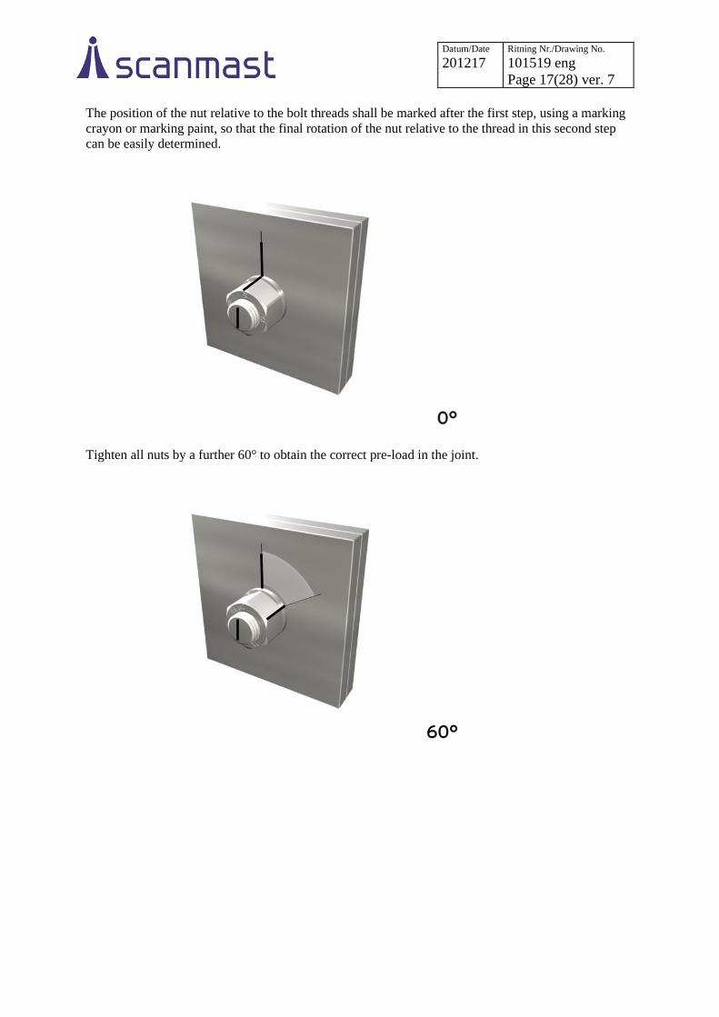
The position of the nut relative to the bolt threads shall be marked after the first step, using a marking
crayon or marking paint, so that the final rotation of the nut relative to the thread in this second step
can be easily determined.
Tighten all nuts by a further 60° to obtain the correct pre-load in the joint.

Datum/Date 201217
Ritning Nr./Drawing No. 101519 eng
Page 18(28) ver. 7
3.2 Ladder bracket 707929 Fits in sections with diagonals up to and including 30 mm. Set consisting of 4 x ladder brackets
positioned according to picture of respective section.
If cable supports fitted with hooks around the rungs are to be used, the ladder bracket must be fitted 25
mm from the ladder pole.
Assemble the ladder with holes 9 mm in the side profile downwards in the section.
Position the clamp around the rung with accompanying screw in its outermost position (to the right in
the left hand picture below) to avoid protruding edges for climbers.
Tighten M10 nut sufficiently without bending the plates.
Then secure all nuts with punch marks.
Washer
10.5x20
Nut M10
Nut M8
Screw M10x60
Screw
M8x25
Washer 8.4x16
105 mm

Datum/Date 201217
Ritning Nr./Drawing No. 101519 eng
Page 19(28) ver. 7
3.3 Ladder bracket 707930 Fits in sections with diagonals larger than 30 mm. Set consisting of 4 x ladder brackets positioned
according to picture of respective section.
If cable supports fitted with hooks around the rungs are to be used, the ladder bracket must be fitted 25
mm from the ladder pole.
Assemble the ladder with holes 9 mm in the side profile downwards in the section.
Position the clamp around the rung with accompanying screw in its outermost position (to the right in
the left hand picture below) to avoid protruding edges for climbers.
Tighten M10 nut sufficiently without bending the plates.
Then secure all nuts with punch marks.
Nut M8
Washer 8.4x16
Nut M10
Screw M10x80 Screw
M8x25
Washer
10.5x20
78 mm
Datum/Date 201217
Ritning Nr./Drawing No. 101519 eng
Page 20(28) ver. 7
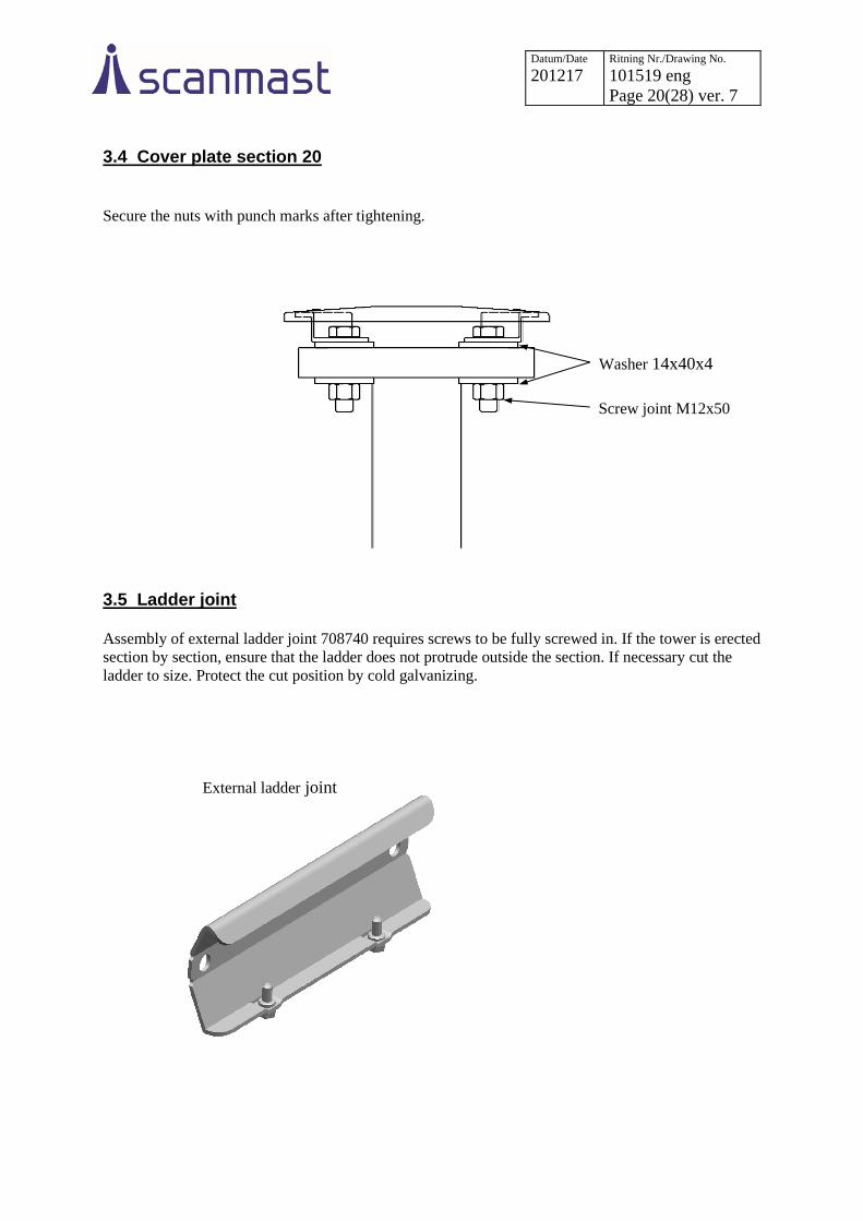
3.4 Cover plate section 20
Secure the nuts with punch marks after tightening.
3.5 Ladder joint Assembly of external ladder joint 708740 requires screws to be fully screwed in. If the tower is erected
section by section, ensure that the ladder does not protrude outside the section. If necessary cut the
ladder to size. Protect the cut position by cold galvanizing.
Washer 14x40x4
Screw joint M12x50
External ladder joint

Datum/Date 201217
Ritning Nr./Drawing No. 101519 eng
Page 21(28) ver. 7
4 ERECTING THE TOWER
4.1 Erecting tower having completely assembled it on the ground
1. Undo the top nut on the foundation bolts. Level the bottom nuts. Place the base plates on the
bottom nuts and level the upper surface of the base plates. Ensure that the bottom nuts (the
washers) are in close contact with the underside of the base plates. Adjust with the starting-
point that the base plates must be as low as possible without any part of them, e.g. the drain
pipe, being in contact with the foundation (cf. illustrations chapter 5 ”Under casting
foundation” in these instructions).
2. Screw on the top nut.
3. Place a lifting strap over the tower's centre of gravity and under a diagonal fixing point
4. Carefully lift the tower with a mobile crane. The lowest section of 11-13 should be stabilised
diagonally using lashing straps before lifting the tower. When the tower is split should the part
without horizontal bracing or welded sections be stabilised diagonally using lashing straps
before lifting the tower. For masts over 42 m or if the installation engineer is inexperienced, it
is recommended that another crane is used to stabilise the bottom end of the tower and prevent
it from dragging on the ground
5. Position the tower on the base plates. Screw in the screws between section and base plate and
tighten the screws and foundation bolts with torque according to table on page 21 and 23.
Centre of gravity
Strap
Top
Datum/Date 201217
Ritning Nr./Drawing No. 101519 eng
Page 22(28) ver. 7
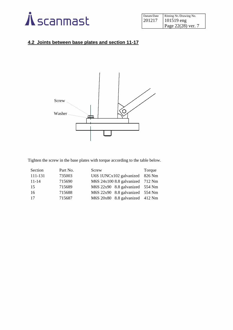
4.2 Joints between base plates and section 11-17
Tighten the screw in the base plates with torque according to the table below.
Section Part No. Screw Torque
111-131 735003 U6S 1UNCx102 galvanized 826 Nm
11-14 715690 M6S 24x100 8.8 galvanized 712 Nm
15 715689 M6S 22x90 8.8 galvanized 554 Nm
16 715688 M6S 22x90 8.8 galvanized 554 Nm
17 715687 M6S 20x80 8.8 galvanized 412 Nm
Screw
Washer

Datum/Date 201217
Ritning Nr./Drawing No. 101519 eng
Page 23(28) ver. 7
5. UNDER CASTING BASE PLATES 5.1 Warranty conditions
Once the tower has been erected the base plates must be under cast. Under casting is required for the
tower to have full load-carrying capacity and for the warranty to apply. Under casting of base plates is
to be done with the mortar specified, for example, BEMIX* expanding frost proof mortar or
equivalent.
The under casting must be somewhat smaller in diameter than the base plate so that water cannot
collect between mortar and base plate.
*www.finjabemix.se
5.2 Section 11-17
5.3 Section 18-19
5.4 Section 20
Drainage holes can be created by means of, for example, a styrofoam wedge below the base plate,
which is removed once the concrete has hardened. Make sure that drainage is free from dirt.
Foundation bolt
Base plate
Under casting
Foundation
Drainage
Foundation bolt
Base plate
Drainage
Foundation
Under casting
Under casting
Foundation bolt
Wedge
Foundation
Examle of under casting

Datum/Date 201217
Ritning Nr./Drawing No. 101519 eng
Page 24(28) ver. 7
6. SPECIFICATIONS
6.1 Torque for tightening screw joints (Does not apply to flange joints between sections!)
Tightening torque, torque wrench
Dimension Lubricant
Oil
M10 50 Nm
M12 87 Nm
M16 211 Nm
M20 412 Nm
M22 554 Nm
M24 712 Nm
UNC 1” 826 Nm
6.2 Torque for tightening foundation bolts Tightening torque, torque wrench
Dimension Lubricant
Oil
M20 218 Nm
M24 377 Nm
M30 746 Nm
6.3 Locking with punch mark Joints that are not secured by torqueing must be secured by punch marking nuts according to the figure
below.
Right Wrong

Datum/Date 201217
Ritning Nr./Drawing No. 101519 eng
Page 25(28) ver. 7
6.4 Weight specifications
Part no. Description Weight, kg
100811 Section 11 1100
100822 Section 111 1230
100812 Section 12 1070
100823 Section 121 1200
100813 Section 13 1040
100824 Section 131 1152
100814 Section 14 815
100825 Section 141 885
100815 Section 15 760
100826 Section 151 825
100816 Section 16 595
100827 Section 161 730
100817 Section 17 575
100828 Section 171 680
100818 Section 18 458
100829 Section 181 515
100819 Section 19 295
100830 Section 191 390
100842 Section 193 398
100820 Section 20 240
715690 Base plate 11-14 63
715689 Base plate 15 51
715688 Base plate 16 51
715687 Base plate 17 30
791138 Base plate 18 5.4
791137 Base plate 19 4.8
706413
Ladder 20
707929 Ladder bracket set 8
707930 Ladder bracket set 8
718836 Cover plate set 2
712670 Fixing template 11 153
711497 Fixing template 12 140
711500 Fixing template 13 127
711503 Fixing template 14 113
711514 Fixing template 15 107
715700 Fixing template 16 94
715701 Fixing template 17 81
719785 Fixing template 18 50
711166 Fixing template 19 38
711167 Fixing template 20 28

Datum/Date 201217
Ritning Nr./Drawing No. 101519 eng
Page 26(28) ver. 7
7. PROPOSAL FOR INSPECTION PLAN
Pos. Description N/A OK Not OK
Observation/comments
1 Delivery inspection of material
2 Ground inspection for foundation
3 Under casting
4 Straightness inspection
5 Verticality inspection
6 Surface finish / mechanical damage
7 Any surface damage touched-up
8 Torque wrench Calibration date
9 Tightening torque foundation bolts
10 Tightening method HR assembling
11 Tightening torque other bolted assembling
12 Any punch marking
13 Climbing barrier fitted as per instructions
14 Earthing of tower
15 Any fall protection fitted as per instructions
16

Datum/Date 201217
Ritning Nr./Drawing No. 101519 eng
Page 27(28) ver. 7
8. OPERATION AND MAINTENANCE
8.1 Operation
Always connect to the Söll fall arrest when climbing.
Personal safety equipment:
• Body harnest according to EN361
• Söll fall arrester type comfort2
• Helmet
• Gloves
• Other equipment according to local regulations
8.2 Maintenance
Inspection checkpoints recommended to be done every year.
Main structure:
• No structure components missing
• No diagonal or tower legs damaged
• Drainage holes are open (base plate and diagonals)
• Top cover allows ventilation
• No bolt assembly missing
• Bolt assemblies are tightened
• Foundation bolts are tightened
• Under casting is in place
• Ground connections are correct
• Galvanisation condition
Foundation:
• Concrete condition above ground
• No water stagnation on concrete block
Accessories:
• No bolt assembly missing
• Bolt assemblies are tightened
• Galvanisation condition
Datum/Date 201217
Ritning Nr./Drawing No. 101519 eng
Page 28(28) ver. 7
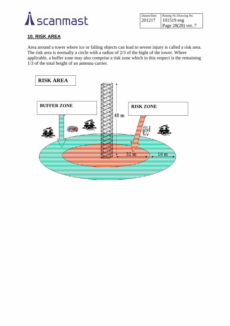
10. RISK AREA
Area around a tower where ice or falling objects can lead to severe injury is called a risk area.
The risk area is normally a circle with a radius of 2/3 of the hight of the tower. Where
applicable, a buffer zone may also comprise a risk zone which in this respect is the remaining
1/3 of the total height of an antenna carrier.
RISK AREA
BUFFER ZONE RISK ZONE