Embed Size (px)
Citation preview
Translation of the original manual
Assembly and Operating manualOPSCollision and Overload Protection
Imprint
202.00 | OPS | Assembly and Operating manual | en | 389668
ImprintCopyright:This manual is protected by copyright. The author is SCHUNK GmbH & Co. KG. All rightsreserved. Any reproduction, processing, distribution (making available to third parties),translation or other usage - even excerpts - of the manual is especially prohibited andrequires our written approval.
Technical changes:We reserve the right to make alterations for the purpose of technical improvement.
Document number: 389668
Version: 02.00 | 22/03/2019 | en
© SCHUNK GmbH & Co. KGAll rights reserved.
Dear Customer,thank you for trusting our products and our family-owned company, the leadingtechnology supplier of robots and production machines.Our team is always available to answer any questions on this product and other solutions.Ask us questions and challenge us. We will find a solution!Best regards,Your SCHUNK team
SCHUNK GmbH & Co. KGSpann- und GreiftechnikBahnhofstr. 106 – 134D-74348 Lauffen/NeckarTel. +49-7133-103-0Fax [email protected]
Table of contents
02.00 | OPS | Assembly and Operating manual | en | 389668
3
Table of contents1 General.................................................................................................................... 5
1.1 About this manual ................................................................................................ 51.1.1 Presentation of Warning Labels ............................................................... 51.1.2 Definition of Terms................................................................................... 61.1.3 Applicable documents .............................................................................. 61.1.4 Sizes .......................................................................................................... 6
1.2 Warranty .............................................................................................................. 61.3 Scope of delivery .................................................................................................. 7
1.3.1 Enclosed pack ........................................................................................... 7
2 Basic safety notes ................................................................................................... 82.1 Intended use......................................................................................................... 82.2 Not intended use.................................................................................................. 82.3 Constructional changes ........................................................................................ 82.4 Spare parts ........................................................................................................... 82.5 Ambient conditions and operating conditions ..................................................... 92.6 Product safety ...................................................................................................... 9
2.6.1 Protective equipment............................................................................... 92.6.2 Constructional changes, attachments, or modifications .......................... 9
2.7 Personnel qualification....................................................................................... 102.8 Personal protective equipment.......................................................................... 112.9 Notes on safe operation ..................................................................................... 112.10 Transport ............................................................................................................ 122.11 Malfunctions....................................................................................................... 122.12 Disposal .............................................................................................................. 122.13 Notes on particular risks..................................................................................... 13
3 Technical Data ........................................................................................................ 14
4 Assembly ................................................................................................................ 154.1 Mechanical connection ...................................................................................... 154.2 Electrical connection .......................................................................................... 18
4.2.1 Sensor PNP-Version (standard) .............................................................. 184.2.2 Sensor NPN-Version (special) ................................................................. 20
4.3 Air connections................................................................................................... 214.3.1 Module OPS 80-100................................................................................ 214.3.2 Module OPS 160-300.............................................................................. 214.3.3 Maximum operating pressure ................................................................ 21
4.4 How to dertermine the operating pressure ....................................................... 224.4.1 Calculation of the input air pressure (P) ................................................. 22

Table of contents
402.00 | OPS | Assembly and Operating manual | en | 389668
5 Troubleshooting ..................................................................................................... 265.1 OPS does not react? ........................................................................................... 265.2 OPS does not lock? ............................................................................................. 265.3 No electrical signal?............................................................................................ 26
6 Maintenance .......................................................................................................... 27

General
02.00 | OPS | Assembly and Operating manual | en | 389668
5
1 General1.1 About this manual
This manual contains important information for a safe andappropriate use of the product.This manual is an integral part of the product and must be keptaccessible for the personnel at all times.Before starting work, the personnel must have read andunderstood this operating manual. Prerequisite for safe working isthe observance of all safety instructions in this manual.Illustrations in this manual are provided for basic understandingand may differ from the actual product design.In addition to these instructions, the documents listed underApplicable documents [} 6] are applicable.
1.1.1 Presentation of Warning Labels
To make risks clear, the following signal words and symbols areused for safety notes.
DANGERDanger for persons!Non-observance will inevitably cause irreversible injury or death.
WARNINGDangers for persons!Non-observance can lead to irreversible injury and even death.
CAUTIONDangers for persons!Non-observance can cause minor injuries.
NOTICEMaterial damage!Information about avoiding material damage.
General
602.00 | OPS | Assembly and Operating manual | en | 389668
1.1.2 Definition of Terms
The term "product" replaces the product name on the title page inthis manual.
1.1.3 Applicable documents
• General terms of business*• Catalog data sheet of the purchased product *The documents marked with an asterisk (*) can be downloaded onour homepage schunk.com
1.1.4 Sizes
This operating manual applies to the following sizes:• OPS 80• OPS 100• OPS 160• OPS 200• OPS 300 (special)
1.2 WarrantyIf the product is used as intended, the warranty is valid for 24months from the ex-works delivery date under the followingconditions:• Observe the applicable documents, Applicable documents
[} 6]• Observe the ambient conditions and operating conditions,
Ambient conditions and operating conditions [} 9]
General
02.00 | OPS | Assembly and Operating manual | en | 389668
7
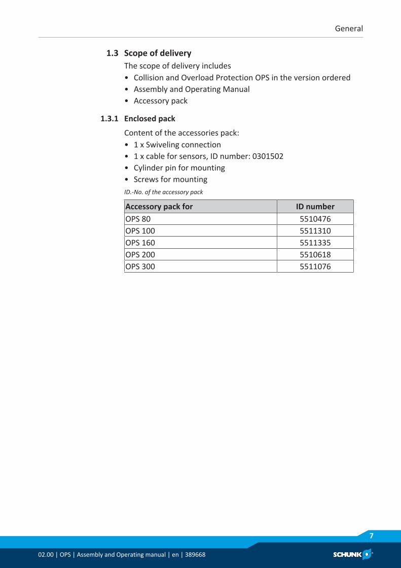
1.3 Scope of deliveryThe scope of delivery includes• Collision and Overload Protection OPS in the version ordered• Assembly and Operating Manual• Accessory pack
1.3.1 Enclosed pack
Content of the accessories pack:• 1 x Swiveling connection• 1 x cable for sensors, ID number: 0301502• Cylinder pin for mounting• Screws for mountingID.-No. of the accessory pack
Accessory pack for ID numberOPS 80 5510476OPS 100 5511310OPS 160 5511335OPS 200 5510618OPS 300 5511076
Basic safety notes
802.00 | OPS | Assembly and Operating manual | en | 389668
2 Basic safety notes2.1 Intended use
The Kollision- and Overload Protection OPS was designed as adevice to protect robots and handling unit from damage resultingfrom collisions and overload conditions.• The product may only be used within the scope of its technical
data, Technical Data [} 14].• When implementing and operating components in safety-
related parts of the control systems, the basic safety principlesin accordance with DIN EN ISO 13849-2 apply. The proven safetyprinciples in accordance with DIN EN ISO 13849-2 also apply tocategories 1, 2, 3 and 4.
• The product is intended for industrial and industry-oriented use.• The product is intended for installation in a machine/system.
The applicable guidelines must be observed and complied with.• Appropriate use of the product includes compliance with all
instructions in this manual.
2.2 Not intended useIt is not intended use if the product is used, for example, as apressing tool, stamping tool, lifting gear, guide for tools, cuttingtool, clamping device or a drilling tool.• Any utilization that exceeds or differs from the appropriate use
is regarded as misuse.
2.3 Constructional changesImplementation of structural changesBy conversions, changes, and reworking, e.g. additional threads,holes, or safety devices can impair the functioning or safety of theproduct or damage it.• Structural changes should only be made with the written
approval of SCHUNK.
2.4 Spare partsUse of unauthorized spare partsUsing unauthorized spare parts can endanger personnel anddamage the product or cause it to malfunction.• Use only original spare parts or spares authorized by SCHUNK.

Basic safety notes
02.00 | OPS | Assembly and Operating manual | en | 389668
9
2.5 Ambient conditions and operating conditionsRequired ambient conditions and operating conditionsIncorrect ambient and operating conditions can make the productunsafe, leading to the risk of serious injuries, considerable materialdamage and/or a significant reduction to the product's life span.• Make sure that the product is used only in the context of its
defined application parameters, Technical Data [} 14].• Make sure that the product is a sufficient size for the
application.• Make sure that the environment is free from splash water and
vapors as well as from abrasion or processing dust. Exceptionsare products that are designed especially for contaminatedenvironments.
2.6 Product safetyDangers arise from the product, if:• the product is not used in accordance with its intended
purpose.• the product is not installed or maintained properly.• the safety and installation notes are not observed.Avoid any manner of working that may interfere with the functionand operational safety of the product.Wear protective equipment.
NOTEMore information is contained in the relevant chapters.
2.6.1 Protective equipment
Provide protective equipment per EC Machinery Directive.
2.6.2 Constructional changes, attachments, or modifications
Additional drill holes, threads, or attachments that are not offeredas accessories by SCHUNK may be attached only with permissionfrom SCHUNK.

Basic safety notes
1002.00 | OPS | Assembly and Operating manual | en | 389668
2.7 Personnel qualificationInadequate qualifications of the personnelIf the personnel working with the product is not sufficientlyqualified, the result may be serious injuries and significantproperty damage.• All work may only be performed by qualified personnel.• Before working with the product, the personnel must have read
and understood the complete assembly and operating manual.• Observe the national safety regulations and rules and general
safety instructions.
The following personal qualifications are necessary for the variousactivities related to the product:
Trained electrician Due to their technical training, knowledge and experience, trainedelectricians are able to work on electrical systems, recognize andavoid possible dangers and know the relevant standards andregulations.
Qualified personnel Due to its technical training, knowledge and experience, qualifiedpersonnel is able to perform the delegated tasks, recognize andavoid possible dangers and knows the relevant standards andregulations.
Instructed person Instructed persons were instructed by the operator about thedelegated tasks and possible dangers due to improper behaviour.
Service personnel ofthe manufacturer
Due to its technical training, knowledge and experience, servicepersonnel of the manufacturer is able to perform the delegatedtasks and to recognize and avoid possible dangers.

Basic safety notes
02.00 | OPS | Assembly and Operating manual | en | 389668
11
2.8 Personal protective equipmentUse of personal protective equipmentPersonal protective equipment serves to protect staff againstdanger which may interfere with their health or safety at work.• When working on and with the product, observe the
occupational health and safety regulations and wear therequired personal protective equipment.
• Observe the valid safety and accident prevention regulations.• Wear protective gloves to guard against sharp edges and
corners or rough surfaces.• Wear heat-resistant protective gloves when handling hot
surfaces.• Wear protective gloves and safety goggles when handling
hazardous substances.• Wear close-fitting protective clothing and also wear long hair in
a hairnet when dealing with moving components.
2.9 Notes on safe operationIncorrect handling of the personnelIncorrect handling and assembly may impair the product's safetyand cause serious injuries and considerable material damage.• Avoid any manner of working that may interfere with the
function and operational safety of the product.• Use the product as intended.• Observe the safety notes and assembly instructions.• Do not expose the product to any corrosive media. This does
not apply to products that are designed for specialenvironments.
• Eliminate any malfunction immediately.• Observe the care and maintenance instructions.• Observe the current safety, accident prevention and
environmental protection regulations regarding the product'sapplication field.

Basic safety notes
1202.00 | OPS | Assembly and Operating manual | en | 389668
2.10 TransportHandling during transportIncorrect handling during transport may impair the product'ssafety and cause serious injuries and considerable materialdamage.• When handling heavy weights, use lifting equipment to lift the
product and transport it by appropriate means.• Secure the product against falling during transportation and
handling.• Stand clear of suspended loads.
2.11 MalfunctionsBehavior in case of malfunctions• Immediately remove the product from operation and report the
malfunction to the responsible departments/persons.• Order appropriately trained personnel to rectify the
malfunction.• Do not recommission the product until the malfunction has
been rectified.• Test the product after a malfunction to establish whether it still
functions properly and no increased risks have arisen.
2.12 DisposalHandling of disposalThe incorrect handling of disposal may impair the product's safetyand cause serious injuries as well as considerable material andenvironmental harm.• Follow local regulations on dispatching product components for
recycling or proper disposal.
Basic safety notes
02.00 | OPS | Assembly and Operating manual | en | 389668
13
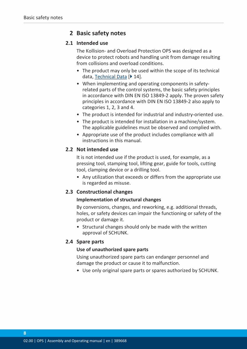
2.13 Notes on particular risksGenerally valid:• Remove the energy supplies before installation, modification,
maintenance, or adjustment work.• Make sure that no residual energy remains in the system.• Do not move parts by hand when the energy supply is
connected.• Do not reach into the open mechanism or the movement area
of the unit.• Perform maintenance, modifications, and additions outside the
danger zone.• Secure the product during all operations against uncontrolled
activation.• Take a precautionary approach by maintenance and
disassembly.• Only specially trained staff should disassemble the product.
WARNINGRisk of injury when the machine/system moves unexpectedly.
WARNINGWhile disassembling uncontrollable moves of parts of thegripper possible!
WARNINGpossibility of uncontrolled movements of individual parts of themodule during dissassembly!
Technical Data
1402.00 | OPS | Assembly and Operating manual | en | 389668
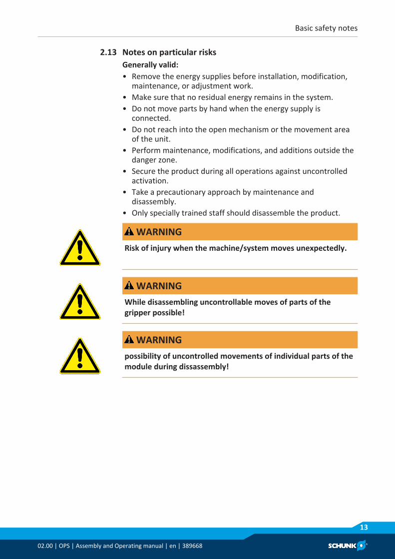
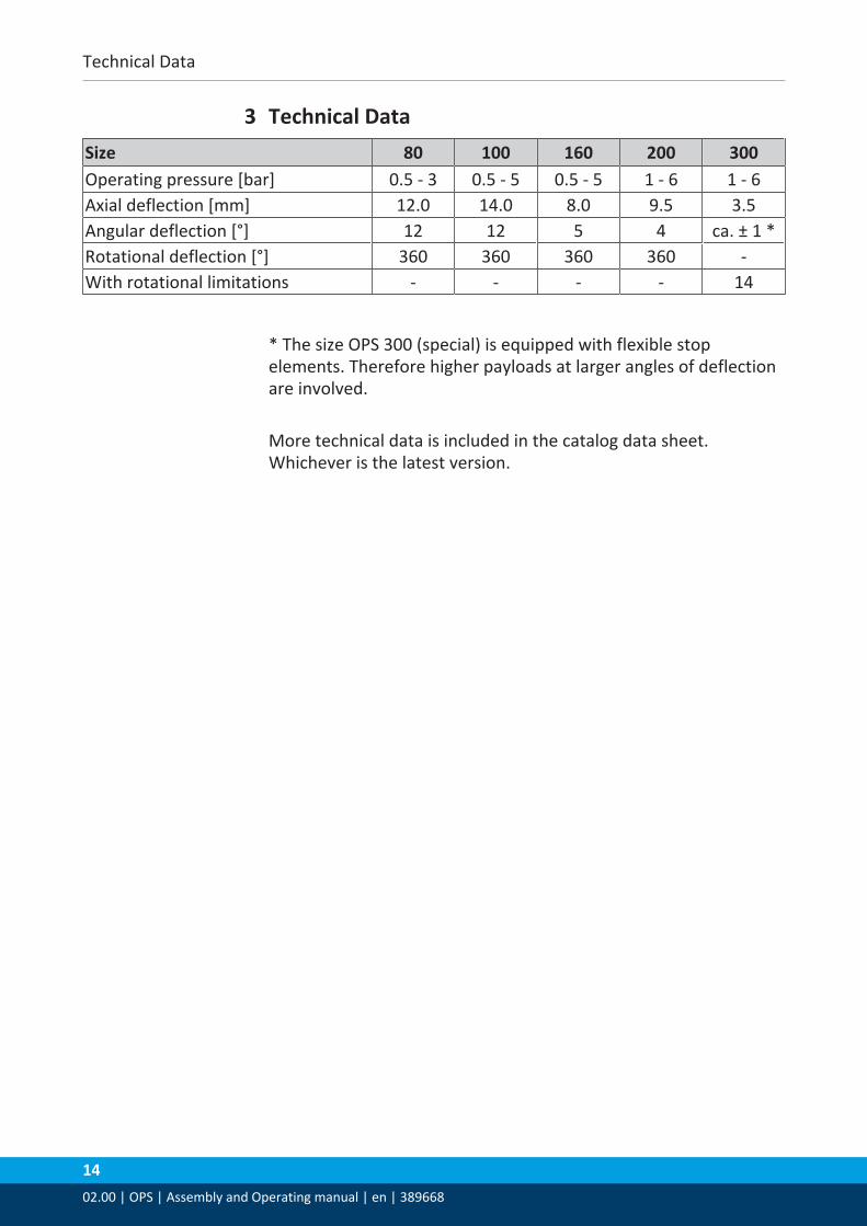
3 Technical DataSize 80 100 160 200 300Operating pressure [bar] 0.5 - 3 0.5 - 5 0.5 - 5 1 - 6 1 - 6Axial deflection [mm] 12.0 14.0 8.0 9.5 3.5Angular deflection [°] 12 12 5 4 ca. ± 1 *Rotational deflection [°] 360 360 360 360 -With rotational limitations - - - - 14
* The size OPS 300 (special) is equipped with flexible stopelements. Therefore higher payloads at larger angles of deflectionare involved.
More technical data is included in the catalog data sheet.Whichever is the latest version.

Assembly
02.00 | OPS | Assembly and Operating manual | en | 389668
15
4 Assembly4.1 Mechanical connection
OPS 80
Item Designation Item Designation1 Sensor connection 3 Air connection2 NotchA Tool side4 Cylinder head screw 4 x M6 5 Cylindrical pin 2x Ø 6mmB Robot side6 Cylinder head screw 3 x M4 7 Cylindrical pin 2x Ø 4mm
OPS 100
Item Designation Item Designation1 Sensor connection 3 Air connection2 NotchA Tool side4 Cylinder head screw 6 x M8 5 Cylindrical pin 2x Ø 8mmB Robot side6 Cylinder head screw 6 x M5 7 Cylindrical pin 2x Ø 5mm

Assembly
1602.00 | OPS | Assembly and Operating manual | en | 389668
OPS 160
Item Designation Item Designation1 Sensor connection 3 Air connection2 NotchA Tool side4 Cylinder head screw 6 x M10 5 Cylindrical pin 2x Ø 10mmB Robot side6 Cylinder head screw 6 x M8 7 Cylindrical pin 2x Ø 8mm
OPS 200
Item Designation Item Designation1 Air connection 3 Notch2 Sensor connectionA Tool side4 Cylinder head screw 6 x M10 5 Cylindrical pin 2x Ø 10mmB Robot side6 Cylinder head screw 6 x M8 7 Cylindrical pin 2x Ø 8mm

Assembly
02.00 | OPS | Assembly and Operating manual | en | 389668
17
OPS 300 (special)
Item Designation Item Designation1 Air connection 3 Notch2 Sensor connectionA Tool side4 Cylinder head screw 6 x M10 5 Cylindrical pin 2x Ø 10mmB Robot side6 Cylinder head screw 6 x M8 7 Cylindrical pin 2x Ø 8mm
NOTEThe basic position of the OPS is clearly defined, since it only snapsin a certain position.The OPS snaps, when the notch of the flange is aligned with thenotch on the housing.
Assembly
1802.00 | OPS | Assembly and Operating manual | en | 389668
4.2 Electrical connection
DANGERDanger from electric voltage!Touching live parts can result in death.• Switch off energy supply before carrying out all assembly,
adjustment and maintenance work and secure against re-connection.
• Electrical installation may only be performed by a qualifiedelectrician.
• Ensure that there is no voltage, ground and short-circuit thesystem.
• Cover up live parts.
WARNINGFor connection of inductive loads switch a recovery diodeparallely to the load!Please make sure that power supply will be correctly polarized.The electronic has a reverse battery protection.
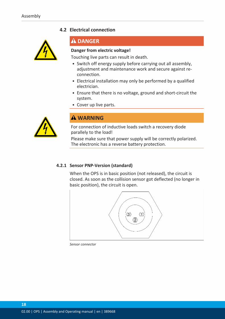
4.2.1 Sensor PNP-Version (standard)
When the OPS is in basic position (not released), the circuit isclosed. As soon as the collision sensor got deflected (no longer inbasic position), the circuit is open.
Sensor connector

Assembly
02.00 | OPS | Assembly and Operating manual | en | 389668
19
Circuit diagram sensor PNP-Version
Item Designation Color1 +24V Brown2 Signal Black3 GND Blue4 Load
Designation ValuePower supply [VDC] 10 ... 30 (Remaining ripple max. 10%)Power demand [mA] Max. 7.5 (wihtout load at 24 V)Voltage drop [V] Max. 3,6Output PNP switchingMax. power output [mA] 180 (resistive load); short circuit proofOutput signal OPS locked – transistor leading
OPS unlocked – transistor not leading
Assembly
2002.00 | OPS | Assembly and Operating manual | en | 389668
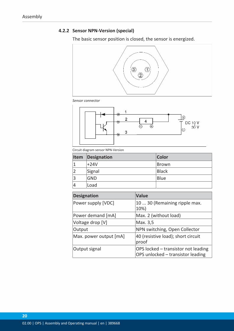
4.2.2 Sensor NPN-Version (special)
The basic sensor position is closed, the sensor is energized.
Sensor connector
Circuit diagram sensor NPN-Version
Item Designation Color1 +24V Brown2 Signal Black3 GND Blue4 Load
Designation ValuePower supply [VDC] 10 ... 30 (Remaining ripple max.
10%)Power demand [mA] Max. 2 (without load)Voltage drop [V] Max. 3,5Output NPN switching, Open CollectorMax. power output [mA] 40 (resistive load); short circuit
proofOutput signal OPS locked – transistor not leading
OPS unlocked – transistor leading

Assembly
02.00 | OPS | Assembly and Operating manual | en | 389668
21
4.3 Air connections
NOTICEObserve the requirements for the air supply Technical Data [} 14].
The compressed air must be filtered (10 μm), dry, oiled or unoiled.Standard for quality of the compressed air according to ISO8573-1: 6 4 4.
4.3.1 Module OPS 80-100
Compressed air connection at the throttle check valve ensue witha hose Ø4 x 1.
4.3.2 Module OPS 160-300
Compressed air connection at the throttle check valve ensue witha hose Ø6 / Ø4.
4.3.3 Maximum operating pressure
• OPS 80: 3 bar• OPS 100: 5 bar• OPS 160: 5 bar• OPS 200: 6 bar• OPS 300: 6 bar
Assembly
2202.00 | OPS | Assembly and Operating manual | en | 389668
4.4 How to dertermine the operating pressure
NOTICEThe OPS deflects during deaeration!• During deflection air will exhaust permanently from the OPS. If
this should have to be avioded, the compressed air should beswitched off via an external valve during this time.
• If the facility should be switched off, please make sure that theair supply of theOPS is assured. If this shouldn’t be possible,the OPS has to be positioned in a way that no more deflectionmay occur (possibly via devices or hanging position). During alonger stillstand, for example over night or weekend put theOPS always in a hanging position
NOTE• Because of an attached throttle check valve the pressure in the
OPS can be short term maintain. This is especially importantduring assembly work.
• Before adjusting the operating pressure open the throttle checkvalve by turning the adjusting screw to the left.
4.4.1 Calculation of the input air pressure (P)
For the rough calculation of the input air pressure use thefollowing formulas and charts:• Fy und Fz:
force (F) out of mass (m) and acceleration (a) calculated in N,F=m·a
• My und Mz:Moment (M) out of force (F) and lever arm (L) calculated in Nm,M=F·L
• P:input air pressure in bar
• S:center of gravity
• D:Distance of the mounting surfaceOPS to the center of gravity (S)in mm
The determined input air pressure (P) must be within theoperating pressure range of theOPS, Technical Data [} 14].

Assembly
02.00 | OPS | Assembly and Operating manual | en | 389668
23
Module OPS 80
Calculation input air pressure OPS 80
Module OPS 100
Calculation input air pressure OPS 100

Assembly
2402.00 | OPS | Assembly and Operating manual | en | 389668
Module OPS 160
Calculation input air pressure OPS 160
Module OPS 200
Calculation input air pressure OPS200

Assembly
02.00 | OPS | Assembly and Operating manual | en | 389668
25
Module OPS 300 (special)
Calculation input air pressure OPS 300 (special)

Troubleshooting
2602.00 | OPS | Assembly and Operating manual | en | 389668
5 Troubleshooting5.1 OPS does not react?
Possible cause Corrective actionOperating pressure too high Check operating pressure, Maximum
operating pressure [} 21]
5.2 OPS does not lock?Possible cause Corrective actionBasic alignment is incorrect Turn module to basic position, Mechanical
connection [} 15]Dirt deposits in the piston chamber Remove the cover, Clean and lubricate
product, Maintenance [} 27]Supply voltage too low Check operating pressure, Maximum
operating pressure [} 21]Piston sealing is defective Replace the seals, Maintenance [} 27]
5.3 No electrical signal?Possible cause Corrective actionCable connected incorrectly Check circular connections and both
miniature flat connections on the right seat.Electrical outputs not connected correctly Check pin allocation.Installed electrical signal transmitterdefective
Send the product to SCHUNK with a repair order.
Cable breakage Exchange cable
Maintenance
02.00 | OPS | Assembly and Operating manual | en | 389668
27
6 MaintenanceCollision and Overload protection OPS is maintenance-free.• Carefully clean the OPS from dirt with a soft cloth.• Don’t use any solvents.• Pay attention that no dirt penetrates into piston area when OPS
is depressurized.
NOTICEProximity switches are poured in and can not be removed. If the proximity switches or seals should be damaged, return theOPS for repair to SCHUNK.

2802.00 | OPS | Assembly and Operating manual | en | 389668