Embed Size (px)
Citation preview

Dulcodes S UV Systemfor the aquatics market
Assembly and operating instructions
A0103
Please stick the nameplate here
Original Operating Instructions (2006/42/EC)Part number 985574 BA DS 002 04/13 US
Please carefully read these operating instructions before use! · Do not discard!The operator shall be liable for any damage caused by installation or operating errors!
Technical changes reserved.

In order to make it easier to read, this document uses the maleform in grammatical structures but with an implied neutral sense. Itis aimed equally at both men and women. We kindly ask femalereaders for their understanding in this simplification of the text.
Please read the supplementary information in its entirety.The following are highlighted separately in the document:n Enumerated lists
Instructions
ð Outcome of the instructions
InformationThis provides important information relating to the correct operationof the device or is intended to make your work easier.Safety notesThe safety information includes detailed descriptions of the haz‐ardous situation, see Ä Chapter 2.1 “Explanation of the safetyinstructions” on page 7
General non-discriminatory approach
Supplementary information
Supplemental instructions
2

Table of contents1 About this system.................................................................. 5
1.1 Correct and proper use................................................. 62 Safety chapter....................................................................... 7
2.1 Explanation of the safety instructions........................... 72.2 Users' qualifications...................................................... 82.3 Dulcodes safety information......................................... 82.4 Safety Equipment......................................................... 92.5 Information in the event of an emergency.................. 10
3 Function.............................................................................. 113.1 Commissioning........................................................... 113.2 Normal mode.............................................................. 113.3 Automatic wiper.......................................................... 113.4 Temperature monitoring............................................. 123.5 Switching off............................................................... 123.6 Cool down................................................................... 12
4 Control................................................................................ 134.1 Display........................................................................ 134.2 Operating status display and parameter settings....... 154.2.1 Trend display........................................................... 164.2.2 Changing access code............................................ 174.2.3 Set the local language............................................. 174.2.4 Calibrating the sensor.............................................. 174.2.5 Triggering the wiper cycle........................................ 184.2.6 Setting the safety threshold..................................... 184.2.7 Setting the warning threshold.................................. 194.2.8 Adjusting the wiper interval...................................... 204.2.9 Adjusting the display range of the trend display...... 204.2.10 Analogue output UV sensor signal: Assigning the
standard signal...................................................... 204.2.11 Pause function....................................................... 214.2.12 Displaying/resetting the counter............................ 214.2.13 Alarm signal relay.................................................. 22
5 Mounting and installation.................................................... 235.1 Radiation chamber...................................................... 245.1.1 Assembly................................................................. 265.1.2 Attach the warning label.......................................... 265.1.3 Hydraulic connectors............................................... 265.2 Control cabinet and control......................................... 275.2.1 Assembly................................................................. 275.2.2 Electrical connections.............................................. 275.2.3 Fitting the temperature sensor................................. 275.3 Installing the UV lamp protection tube........................ 275.3.1 Installing the UV lamp protection tube without the
wiper........................................................................ 275.3.2 Installing the UV lamp protection tube with manual
wiper........................................................................ 285.3.3 Fitting the UV lamp protection tube with automatic
wiper........................................................................ 295.4 Assembly and connection of the UV Lamp................. 305.5 Retrofitting a manual wiper......................................... 31
Table of contents
3
5.5.1 Removing the UV lamp protection tube with manualwiper........................................................................ 31
5.5.2 Assembly and installation of the manual wiper........ 335.6 Retrofitting an automatic wiper................................... 345.6.1 Removing the UV lamp protection tube with auto‐
matic wiper............................................................... 355.6.2 Assembly and installation of the automatic wiper.... 37
6 Commissioning................................................................... 426.1 Leak testing and ventilation of the radiation chamber 426.2 Switching on the UV system....................................... 426.3 Calibrating the UV sensor........................................... 436.3.1 UV Sensor calibration.............................................. 43
7 Maintenance....................................................................... 447.1 Cleaning...................................................................... 457.1.1 Cleaning the UV lamp protection tube..................... 457.1.2 Cleaning with a manual wiper.................................. 457.1.3 Cleaning after dismantling the UV lamp protection
tube.......................................................................... 477.1.4 Cleaning with a cleaning solution............................ 497.1.5 Cleaning the UV Sensor.......................................... 507.2 Replacing the wiper elements (systems with manual
wiper).......................................................................... 517.3 Replace the O-ring on the clamping screw................. 537.4 Maintenance of the automatic wiper........................... 557.4.1 Replacing the wiper elements (UV systems with
automatic wiper)...................................................... 557.5 Replacing the lamp..................................................... 587.6 Calibrating the UV sensor........................................... 607.7 Replacing the filter mats............................................. 60
8 Troubleshooting.................................................................. 619 Technical data..................................................................... 64
9.1 Dimensions sheet....................................................... 659.2 Electrical data............................................................. 67
10 Appendix............................................................................. 6910.1 Spare parts 1 kW - 3 kW single UV lamp system
without wiper or manual wiper.................................. 6910.2 Spare parts 1 kW - 3 kW single UV lamp system
with automatic wiper................................................. 7210.3 Spare parts 2x2 kW, 2x3 kW, 3x3 kW multiple UV
lamp system with automatic wiper............................ 7610.4 Dulcodes S Terminal Wiring Diagram....................... 8010.5 Dulcodes UV system unit operating log.................... 81
11 EC Declaration of Conformity............................................. 8212 Index................................................................................... 84
Table of contents
4

1 About this system
The Dulcodes S UV systems are used for photochemical treatmentand to support the disinfection of:n Process watern Swimming pool waterIn the treatment of swimming pool water, harmful substances, suchas chloramines, can be effectively reduced by UV radiation andalso germs, which are difficult to inactivate with chlorine, can besafely killed.The Dulcodes UV systems are supplied fully wired. They are avail‐able in different versions, which are defined by their identity code.The performance data can be found in the data sheet enclosedwith the Dulcodes UV system.Scope of supplyn Radiation chambern Lamp with lamp protection tuben UV-C sensorn Temperature switchn Control cabinet with controln Mounting materialsn DocumentationDependent on the system type, the system is equipped with nowiper, a manual wiper or an automatic wiper. Retrofitting with amanual or automatic wiper is easily possible.
Allocation of wiper versions to the device types
Device type Without wiper Manual wiper(manual wiper)
Automatic Wiper(automatic wiper)
1.00 kW X O O
2.00 kW X O O
3.00 kW X O O
2x2.00 kW ---- ---- O
3x2.00 kW ---- ---- O
3x3.00 kW ---- ---- O
X = standard; O = optional; ---- = not available
Application
About this system
5

1.1 Correct and proper use
Correct and proper use– The UV system is intended solely for the treatment of water.– The UV system may only be used in accordance with the tech‐
nical data and specifications outlined in the Operating Manual.– Any other use or modification of the system is prohibited.– The UV system must only be operated by trained and author‐
ized personnel.– You are obliged to observe the information contained in the
operating instructions at the different phases of the device'sservice life.
The operator shall be liable for any damage caused by installationor operating errors.
About this system
6

2 Safety chapter
2.1 Explanation of the safety instructions
These operating instructions provide information on the technicaldata and functions of the product. These operating instructions pro‐vide detailed safety information and are provided as clear step-by-step instructions.The safety information and notes are categorized according to thefollowing scheme. A number of different symbols are used todenote different situations. The symbols shown here serve only asexamples.Nature and source of the dangerDanger!– Denotes an immediate threatening danger. If this is disre‐
garded, it will result in fatal or very serious injuries.Consequence: Fatal or very serious injuries Measure to be taken toavoid this danger.Nature and source of the dangerWarning!– Denotes a possibly dangerous situation. If this is disregarded, it
could result in fatal or very serious injuries.Possible consequence: Fatal or very serious injuries Measure to betaken to avoid this dangerNature and source of the dangerCaution!– Denotes a possibly dangerous situation. If not avoided, it could
result in slight or minor injuries. May also be used as a warningabout material damage.
Possible consequence: Slight or minor injuries Material damage.Measure to be taken to avoid this danger.Nature and source of the dangerNote!– Denotes a possibly damaging situation. If not avoided, the
product or an object in its vicinity could be damaged.Damage to the product or its surroundings Measure to be taken toavoid this danger.Type of informationInformation!– Denotes hints on use and other especially useful information. It
does not indicate a hazardous or damaging situation.Hints on use and additional information. Source of information.Additional measures
Introduction
L DANGER
L WARNING
L CAUTION
NOTICE
Safety chapter
7

2.2 Users' qualifications
Danger of injury with inadequately qualified personnel!– All work on the unit is to be conducted by qualified personnel
only.– Keep unqualified personnel away from the hazard zones.The operator of the plant / device is responsible for ensuring thatthe qualifications are fulfilled. If inadequately qualified personnelwork on the unit or loiter in the hazard zone of the unit, this couldresult in dangers that could cause serious injuries and materialdamage.
Training Definition
Instructed personnel An instructed person is deemed to be a person instructed and, if required,trained in the tasks assigned and possible dangers resulting from improperbehavior, as well as having been instructed in the required protective equip‐ment and protective measures.
Trained user A trained user is a person who fulfills the requirements of an instructed personand who has also received additional training specific to the system fromProMinent or another authorized distribution partner.
Trained qualified per‐sonnel
A qualified employee is deemed to be a person who is able to assess thetasks assigned and recognize possible hazards based on his/her training,knowledge and experience, as well as knowledge of pertinent regulations.The assessment of a person's technical training can also be based on severalyears of work in the relevant field.
Electrician Electricians are deemed to be people, who are able to complete work on elec‐trical systems and recognize and avoid possible dangers independently basedon their technical training and experience, as well as knowledge of pertinentstandards and regulations.Electricians are specifically trained for the working environment in which theyare employed and know the relevant standards and regulations.Electricians must comply with the provisions of the applicable statutory direc‐tives on accident prevention.
Service Service refers to service technicians, who have received proven training andhave been authorized by ProMinent to work on the system.
Note for the system operatorThe pertinent accident prevention regulations, as well as all othergenerally acknowledged safety regulations must be observed.
2.3 Dulcodes safety information
UV-C radiationUV-C radiation is harmful to the eyes and skin.– Only operate the UV lamp UV-C when it is fully fitted and installed– Install the UV lamp into the UV system in accordance with the
regulations prior to commissioningPossible consequence: Serious injuries
L WARNING
L WARNING
Safety chapter
8

Live parts!– Measure: The device must be disconnected from the power
supply before it is opened– Disconnect damaged, defective or manipulated devices from
the power supplyPossible consequence: Fatal or very serious injuriesInsufficient water treatmentEnsure that– the maximum permissible water flow rate is not exceeded and– UV transmission does not drop below the permissible level.
– Otherwise adequate treatment cannot be guaranteed.Possible consequence: Illness Please read the technical datasheet for your UV systemOverheating of lamp and treatment chamber– Ensure that, with the exception of when the UV lamp is
warming up, there is sufficient flow through the radiationchamber so that overheating of the radiation chamber isavoided.
– Only switch on the UV system after the radiation chamber hasbeen filled with water.
– Switch the UV system off if the flow of water is interrupted.Possible consequence: Material damageUnauthorized operating parameterEnsure that– the installation place is dry and frost-proof,– the protection of the UV system from chemicals, dyes and
vapors is guaranteed,– the ambient temperature and the radiation temperature in the
direct vicinity of the system does not exceed 104.0°F,– the maximum permissible operating pressure is not exceeded,
and– there are no solid particles or turbidity in the water to be
treated.– If necessary, install a suitable filter prior to the UV system.Possible consequence: Material damage
2.4 Safety Equipment ATTENTION: Hazardous ultraviolet radiation
UV-C UV-C radiation is harmful to the eyes and skin. The lamps mayonly be operated when installed. The system is to be installed inaccordance with all pertinent regulations prior to commissioningthe lamps.ATTENTION: Hazard
Disconnect the system from the power supply or switch off themain switch prior to commencing maintenance work on the system.Depressurize the radiation chamber prior to commencing mainte‐nance work.
Disconnect the system from the power supply or switch off themain switch prior to opening the cabinet.
L WARNING
L WARNING
L CAUTION
L CAUTION
Labels on radiation chamber
Labels on switch cabinet
Safety chapter
9

2.5 Information in the event of an emergency
In the event of an emergency, switch the red-yellow main switch onthe side of the switch cabinet to [OFF] or disconnect from thepower supply.
Safety chapter
10

3 Function
The water to be treated flows through the stainless steel chamberpast the UV lamp. The UV radiation kills the germs and reducessubstances, such as chloramines, in the swimming pool water.The medium pressure UV lamp used generates very high UV-Cradiation output, which is particularly effective for the treatment ofwater. The UV lamp is located in a lamp protection tube made ofhigh-grade quartz with a high level of UV permeability.The compact design of the radiation chamber and the optimumflow of radiation result in evenly distributed irradiation of the entirewater flow.A control monitors the UV system along with a UV sensor.
3.1 Commissioning
Once the Dulcodes UV system has been switched on, the UV lampis ignited. Following ignition, the UV lamp needs approx 1 - 3minutes until it has reached its operating temperature.The UV-C sensor monitors the UV lamp: As soon as the UV-Coutput has exceeded the warning threshold, the system switches tonormal operation.If the safety threshold is not exceeded within the maximum permis‐sible warm-up time, the control switches the UV system off andgoes into fault mode.
3.2 Normal mode
In normal mode, the UV sensor continues to monitor the UVoutput:If the UV output falls below the warning threshold: A warning isemitted.If the UV output falls below the safety threshold: The controlswitches the UV system off and goes into fault mode.
3.3 Automatic wiper
During the wiping process, warning and safety thresholds are notmonitored to prevent shadowing caused by the wiper from trig‐gering a false alarm.The wiping process is triggered upon pressing the "Enter" button inthe “Wiper” display. This is independent from the system's “ON”oder “OFF” settings.If you start the wiping process in warm-up mode, the warm-upprocess is stopped; once the wiping process has ended, the warm-up time will be restarted.
During the wiping process, warning and safety thresholds are notmonitored to prevent shadowing caused by the wiper from trig‐gering a false alarm.
Manually triggering a wiper cycle
Regular wiping
Function
11

If you activated interval wiping, a wiping cycle occurs automaticallyafter the set interval has elapsed.
3.4 Temperature monitoring
The water temperature in the radiation chamber is monitored con‐tinuously while the UV lamp is in operation.As soon as the water temperature exceeds the maximum tempera‐ture, the UV system goes into fault mode.
3.5 Switching off When the OFF switch on the UV control is pressed, the UV lamp isswitched off immediately.
3.6 Cool down
As the UV lamp can only be re-ignited after switching off the UVsystem and sufficient cooling, the system goes into cooling mode.After the STOP
START key has been pressed during cool-down, the UVsystem only restarts automatically after the remaining cooling timehas elapsed. Even if pause mode is canceled during cool-down,the UV system only restarts after the cool-down period haselapsed.Only during service workDuring the cool-down period an attempt at ignition can be made bypressing the key.
Function
12

4 Control With the exception of sensor calibration, modifications to the set‐tings should only be undertaken when the UV system is switchedoff.
As the electronics and software are always subject to improve‐ments, the version number has been introduced as a means ofidentification. This number must be provided with complaints. It canbe called up on the display.
The control used in the Dulcodes UV systems is reset in the fac‐tory. Therefore, with many applications a modification of the set‐tings is not required.
4.1 Display
The system is provided with a graphical LCD display.START/STOP keyHold down the STOP
START key for at least 2 seconds. The display will returnto normal for the respective operating mode 5 minutes after the lasttime a key has been pressed.In operating moden Display of the operating moden Warnings are indicated via flashing arrows and displaysn Faults are displayed by means of a flashing fault alertIn programing moden Flashing display of the numerical values and inputs that can be
changed.
®
STOPSTART
2
3
4
5
8
6
7
1
XXXXXX
Fig. 1: Display and operating unit
NOTICE
Version
Default settings
NOTICE
Control
13

Position number Key Function
1 Housing
2 LCD display
5 UP keyIn programing mode: Raises the displayed numerical value or changesan input
7 BACK keyMoves back one level in the menu
6 DOWN keyIn programing mode: Lowers the displayed numerical value or changesan input
8 CHANGE keyIn operating mode: Changes the display windowIn programing mode: Changes adjustable parameters
3STOPSTART
START/STOP keySwitches the UV system on and off
4 ENTER keyIn operating mode: Switches into programing mode or acknowledges afaultIn programing mode: Applies a set value or mode
Control
14

4.2 Operating status display and parameter settings
xxxx h Operationxxxx - times On Standard display
Change of display
Trend display
Analogue output
Safety threshold
Warning threshold
Display range trend display
x Day(s)
BA
Lamp hours
Lamp turn-ons
Pause on Pause contact
Operat. hours
Turn-ons
P_PMA_DS_0015_SW
Start wiper cycle?
Wiper interval
2:00 h:min
Wiper cycle running!-->Time x:xx
Language
Cal. factor =
Time 05:00:00
Fig. 2: Operating status display (with the system running)A + Back to Trend displayB = Change to Programing modeC = Change to "Change Access Code" mode
Control
15

(adjustable numbers/ settings flash)
Memory display 1s
B (Request access code)
Changes are not saved Changes are saved
Back to display window
Access code incorrect
P_PMA_DS_0016_SW
Fig. 3: Programing manualAccess codeOnce the access code has been correctly entered, it is not neces‐sary to re-enter the code for further programing processes; theflashing numbers or settings will appear directly as soon as the key is pressed. The enable code is automatically canceled 5minutes after a key was last pressed or after a return to the Trendor Standard display.
4.2.1 Trend display
Display calibration– Each calibration of the UV sensor is documented by a vertical
continuous line in the trend display.– The content of the trend display is deleted when the display
range changes and when the operating hour counter is reset.1 UV sensor signal2 Warning threshold3 Safety threshold4 Switch on's/off's5 CalibrationThe trend display is used to monitor the aging of the UV-lamps, theformation of a film coating on the lamp protection tubes or changesto the water quality.The progress of the UV sensor signal is shown in a time frame.Horizontal lines show the safety threshold and the warningthreshold respectively. The short vertical lines show when the UVsystem is switched on. The display range of the sensor signal liesbetween 0% and the value, which has been assigned to the ana‐logue output value of 20 mA. The time frame can be adjusted andguarantees an ongoing display: Once the selected time hasexpired, the oldest value is deleted and the new value is displayed.Default settingn Time frame: 100 daysn Maximum value of the UV sensor signal: 120%
Programing manual
NOTICE
NOTICE
Fig. 4: Trend display
Control
16

4.2.2 Changing access code
Changing access codeDefault setting "5000"– Write down the access code!
– Parameters can only be set once the correct access codehas been entered.
– The default access code does not guarantee protection fromunauthorized changes.
New Access code
xxxx
Memory display 1 s
(Request Access code)
Changes are saved
Confirm Access code
xxxx
Access code incorrect Changes are not saved
C
Back to „Change Access Code“ request P_PMA_DS_0017_SW
Fig. 5: Changing access codeTo protect against unauthorized changes of the settings, thesystem control has an access code for the programing mode. Itcan be freely selected by the operator. The programing mode isstill disabled after a change of the access code. It is only unlockedwhen the new access code is entered.
4.2.3 Set the local language
It is possible to select between different languages.
4.2.4 Calibrating the sensor
L CAUTION
Language :
German
Fig. 6: Set the local language
Default setting 1.000
100%
Time 5:00
Cal. factor =1,000
Fig. 7: Calibrating the sensor
Control
17

Incorrect calibration caused by dirty componentsPossible consequences: Insufficient irradiation due to inaccuratecalibration. Ensure that the UV lamp and UV sensors are cleanbefore starting the calibration, see Ä Chapter 7.1.5 “Cleaning theUV Sensor” on page 50 andThe UV sensor must be calibrated when a new UV lamp isinstalled.Safety and warning thresholds are no longer monitored during cali‐bration. For safety reasons, calibration is automatically interruptedafter 5 minutes without the changes made being saved. The timecount down can be seen in the display.The UV sensor signal must be stable before the start of calibration.A changing UV sensor signal shows that the UV lamp has not yetwarmed up sufficiently (5 to 10 minutes).
4.2.5 Triggering the wiper cycle
If an additional cleaning requirement exists, you can trigger a wipercycle additional to those at the programed intervals by pressing thekey.
4.2.6 Setting the safety threshold
UV lamp replacement– Check and possibly reset the safety and warning threshold
when the UV lamp is replaced.– Only a correctly set safety threshold will guarantee ade‐
quate UV radiation.Possible consequence: IllnessMonitoring the safety thresholdDuring automatic wiper operation, the safety threshold is not moni‐tored.Reliable and safe water treatment can no longer be guaranteed ifthe UV-C output falls so low that the UV sensor signal falls belowthe safety threshold. When the signal falls below the safetythreshold on the display, this is shown by two flashing arrows.
NOTICE
Trigger wiper cycle?
Fig. 8: Triggering the wiper cycle
50%
Safetythreshold
Fig. 9: Setting the safety threshold
L WARNING
Control
18

A signal device can be connected to the SAFETY THRESHOLDsignal relay of the control. The relay is closed when the signal fallsbelow the safety threshold.
The safety threshold must be below the warning threshold. It is notpossible to set it above the warning threshold.1. Switch on the UV system using the STOP
START button.2. Wait until the UV lamp has reached its full capacity, i.e. the
UV-C sensor signal must be stable.3. Read the UV-C intensity displayed and note it down.4. Switch off the UV system with the STOP
START button.5. Set the safety threshold to 50%.6. Now set the warning threshold.
4.2.7 Setting the warning threshold
UV lamp replacement– Check and possibly reset the safety and warning threshold
when the UV lamp is replaced.Possible consequence: IllnessMonitoring the warning thresholdDuring automatic wiper operation, the warning threshold is notmonitored.The system issues a warning should the UV-C output drop so farthat the UV sensor signal falls below the warning threshold. To pre‐vent the signal from falling below the safety threshold, it is neces‐sary to clean the UV lamp protection tube, replace the UV lamp, orimprove the water quality improved by means of appropriate watertreatment. When the signal falls below the warning threshold, thisis indicated on the display by a flashing arrow.A signal device can be connected to the WARNING THRESHOLDsignal relay of the control. The relay is closed when the signal fallsbelow the warning threshold.
The warning threshold must be above the safety threshold. It is notpossible to set it below the safety threshold.
Setting the safety threshold
NOTICE
60%
Warning threshold
Fig. 10: Setting the warning threshold
L WARNING
Setting the warning threshold
NOTICE
Control
19

Requirements:n The UV-C intensity is stable.n The safety threshold has been set.
Set the warning threshold to 60%
ð The safety and warning thresholds have been set, thesystem is now ready for operation and can be switchedon using the STOP
START key.
4.2.8 Adjusting the wiper interval
On systems with an automatic wiper, the interval (h:min) betweenwiping can be set between 1:00 and 9:59. Adjustment takes placein steps of one minute each.
4.2.9 Adjusting the display range of the trend display
The recording time of the UV sensor signal for the trend displaycan be adjusted. The value (in days) is interpreted as the timeframe and thus guarantees a continuous display: Whenever theselected period has expired, the oldest value is deleted and thenew value is displayed. The display range can be set between 4 -100 days.
4.2.10 Analogue output UV sensor signal: Assigning the standard signal
0% = 0 mA100% = 20 mA (depending on the settings)
Default setting 2 hours
Wiper interval
2:00 h:min
Fig. 11: Adjusting the wiper interval
Default setting 100 days
Display range Trend display 100 days
Fig. 12: Adjusting the display range ofthe trend display
Default setting
Analog output
120 % = 20 mA
0 % = 0 mA
Fig. 13: Analogue output UV sensorsignal: Assigning the standard signal
Control
20

Maximum value of the trend displayThe UV sensor signal assigned to the 20 mA is simultaneously themaximum value of the trend display. Adjust this UV sensor signalvalue to 120 % of the maximum value so that the trend display cannever "overflow".The signal from the UV sensor can also be recorded for documen‐tation purposes using a recorder. To do so, connect the recorder tothe standard output of the control.It is possible to choose a standard signal between 0 to 20 mA andbetween 4 to 20 mA:n 0 or 4 mA correspond to the 0% UV sensor signal.n The 20 mA value can be allocated to any maximum % value (0
% - 999 %).
4.2.11 Pause function
Default setting: Closed (UV system starts up when the Pause con‐tact is open)The UV system can be switched on and off by opening and closingan external contact that is connected to the Pause input of the con‐trol. It is possible to select whether the UV system starts up with anopen or closed Pause contact.
4.2.12 Displaying/resetting the counter
OPERATING HOUR and CONNECTION counters cannot be reset.
LAMP HOUR and LAMP CONNECTIONS can be reset.
NOTICE
Default setting
Pause onPause contact
closed
Fig. 14: Pause function
Operat. hours 400 h
Turn-ons 25
Fig. 15: OPERATING TIMES andCONNECTIONS
Lamp hours 400 h
Lamp turn-ons 25
Fig. 16: LAMP HOURS and LAMPCONNECTIONS
Control
21

4.2.13 Alarm signal relay
A signal device can be connected to the ALARM signal relay of thecontrol. The relay drops out if there is a fault/malfunction or in theevent of a power failure.
Control
22

5 Mounting and installation
Insufficient disinfection efficiencyEnsure that– the maximum permissible water flow rate is not exceeded and– UV transmission does not drop below the permissible level.
– Otherwise adequate treatment cannot be guaranteed!Possible consequence: Illness Please read the technical datasheet for your system.Unauthorized operating parameterEnsure that– the installation place is dry and frost-proof,– the protection of the UV system from chemicals, dyes and
vapors is guaranteed,– the ambient temperature and the radiation temperature in the
direct vicinity of the system does not exceed 104.0°F,– the maximum permissible operating pressure is not exceeded,
and– there are no solid particles or turbidity in the water to be
treated.– If necessary, install a suitable filter in front of the UV
system.Possible consequence: Material damage.Switching on and offPossibility of increased wear on UV lamp Operate the UV systemin such a way as to avoid switching the UV lamp on and off fre‐quently.
L WARNING
L CAUTION
NOTICE
Mounting and installation
23

5.1 Radiation chamber
A0105
Fig. 17: Layout of the radiation chamber with manual wiper1 Mushroom knob2 Clamping screw3 Chamber cover4 O-ring5 Outlet6 Centering bolt7 Air vent/drain/flushing connection with O-ring
(depending on installation location)8 UV sensor9 O-ring
10 Lamp protection tube11 Lamp12 Inlet13 Wiper element14 Bracket with wiper rod15 Protective earth conductor cable16 Temperature switch17 Support plate for lamp protection tube
Mounting and installation
24

15 9 9 167
979 8 10
14
17
43
2
1
12
11
13
6
5
512
A0559
Fig. 18: Layout of the radiation chamber with automatic wiper1. Motor2. Protective cover3. Chamber cover4. O-ring5. Outlet6. Wiper rod7. Air vent/drain/flushing connection with O-ring
(depending on installation location)8. UV sensor9. O-ring
10. Lamp protection tube11. Lamp12. Inlet13. Wiper element14. Bracket15. Protective earth conductor cable16. Temperature switch17. Support plate UV lamp protection tube
Mounting and installation
25

5.1.1 Assembly
LocationPossibility of reduced power and premature failure of lamp. The UVsystem must be installed in such a way that the UV lamp lies hori‐zontally.Maintenance workLeave adequate room for maintenance work! The clearancerequired can be found in the dimensions sheet enclosed (replace‐ment of lamp protection tube).Attach the radiation chamber using appropriate fixing material (pipeclamp, frame). The installation position can in principle be chosenat random and, if required, can be adapted to conditions on site.Ensure that the UV lamp lies horizontally. In the case of UV sys‐tems equipped with manual wipers, ensure that the wiper can beoperated easily.
5.1.2 Attach the warning label The supplied self-adhesive warning label is to be attached to theradiation chamber so that it is clearly visible.
5.1.3 Hydraulic connectors
Installation instructionsPossibility of incorrect assembly Implement the hydraulic connec‐tion of the radiation chamber in compliance with the applicablegeneral guidelines and local installation regulations.Damage to lamp and wiper elementPossibility of damage to lamp and wiper element. The UV systemmay only be operated when the radiation chamber is completelyfilled with water. In the case of an empty or only partially filled radi‐ation chamber there is a risk of damaging the lamp, radiationchamber ad the wiper element. It must therefore be ensured thatthe radiation chamber cannot run empty when the pump isswitched off.
– Provide valves upstream and downstream of the radiationchamber to shut off the radiation chamber for maintenancework.
– It is also recommended with radiation chambers, which areregularly cleaned by filling them with a cleaning solution, thatthe water drain and vent screws are replaced with suitablevalves.
– With larger radiation chambers, it is recommended that theyare filled through the water drain opening using an appropriateacid-resistant pump.
– If the radiation chamber is filled with a pump, it is also useful tocirculate the cleaning solution through the air vent opening.This will shorten the cleaning time and achieve better results.
Location
L CAUTION
NOTICE
NOTICE
L CAUTION
L CAUTION
NOTICE
Mounting and installation
26

5.2 Control cabinet and control 5.2.1 Assembly
The connecting cable for the UV lamp and the UV sensor cablemust not be extended!The switch cabinet or the mounting panel with control and ballastshould be mounted to the wall or a suitable frame in such a waythat lamp and sensor can be connected to the cables provided.
5.2.2 Electrical connections
Electrical connections– Please observe all generally applicable guidelines and local
installation regulations.– Only carry out maintenance work on the UV system when it
has been disconnected from the power supply!– Connect a protective earth conductor to both the radiation
chamber and the cover of the chamber. Ensure a continuouspower supply by means of a suitable fault current protectionswitch.
– Only an authorized electrician may open the switch cabinet.– Do not extend the connecting cable for the UV lamp or the UV
sensor cable.– The electrical installation must be carried out by an authorized,
qualified electrician using the documents supplied (wiring dia‐gram).
Possible consequence: Fatal or very serious injuries.
5.2.3 Fitting the temperature sensor
Overheating of radiation chamberPossible consequences: Serious injuries and property damage dueto overheating. The radiation chamber may overheat if the tem‐perature sensor is not fitted correctly.The temperature sensor monitoring the water temperature must bescrewed into the socket provided on the radiation chamber.1. Carefully push the O-ring over the thread of the temperature
sensor.2. Screw the temperature sensor "finger-tight" into the sleeve.3. Attach the connecting cable and fix in place.
5.3 Installing the UV lamp protection tube
5.3.1 Installing the UV lamp protection tube without the wiper
1. Using a face spanner wrench, loosen the lamp protectiontube bracket and remove it (place on the holes, not on thethreads).
2. Carefully pull the transport protection (gray plastic pipe) com‐pletely out of the radiation chamber.
3. Carefully push the UV lamp protection tube into the radiationchamber until it reaches its stop position.
NOTICE
L WARNING
L WARNING
Mounting and installation
27
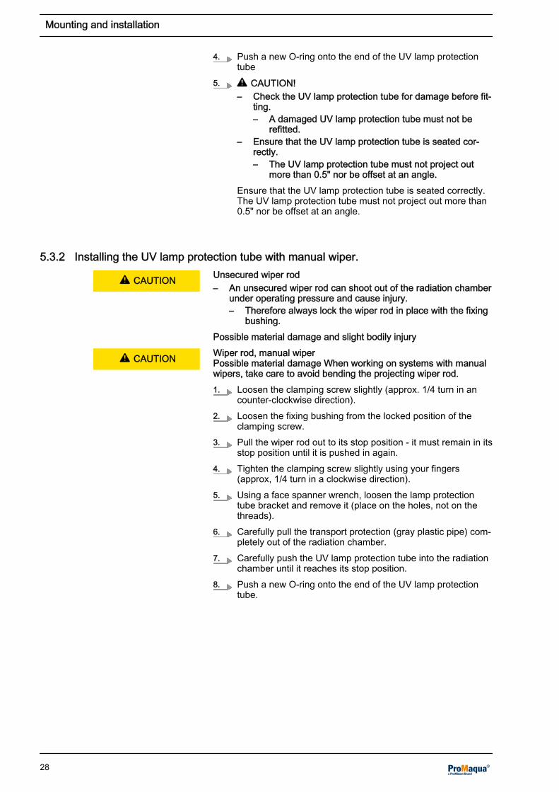
4. Push a new O-ring onto the end of the UV lamp protectiontube
5. L CAUTION!– Check the UV lamp protection tube for damage before fit‐
ting.– A damaged UV lamp protection tube must not be
refitted.– Ensure that the UV lamp protection tube is seated cor‐
rectly.– The UV lamp protection tube must not project out
more than 0.5" nor be offset at an angle.Ensure that the UV lamp protection tube is seated correctly.The UV lamp protection tube must not project out more than0.5" nor be offset at an angle.
5.3.2 Installing the UV lamp protection tube with manual wiper. Unsecured wiper rod– An unsecured wiper rod can shoot out of the radiation chamber
under operating pressure and cause injury.– Therefore always lock the wiper rod in place with the fixing
bushing.Possible material damage and slight bodily injuryWiper rod, manual wiperPossible material damage When working on systems with manualwipers, take care to avoid bending the projecting wiper rod.1. Loosen the clamping screw slightly (approx. 1/4 turn in an
counter-clockwise direction).2. Loosen the fixing bushing from the locked position of the
clamping screw.3. Pull the wiper rod out to its stop position - it must remain in its
stop position until it is pushed in again.4. Tighten the clamping screw slightly using your fingers
(approx, 1/4 turn in a clockwise direction).5. Using a face spanner wrench, loosen the lamp protection
tube bracket and remove it (place on the holes, not on thethreads).
6. Carefully pull the transport protection (gray plastic pipe) com‐pletely out of the radiation chamber.
7. Carefully push the UV lamp protection tube into the radiationchamber until it reaches its stop position.
8. Push a new O-ring onto the end of the UV lamp protectiontube.
L CAUTION
L CAUTION
Mounting and installation
28

9. L CAUTION!– Check the UV lamp protection tube for damage before fit‐
ting.– A damaged UV lamp protection tube must not be
refitted.– Ensure that the UV lamp protection tube is seated cor‐
rectly.– The UV lamp protection tube must not project out
more than 0.5" nor be offset at an angle.Ensure that the UV lamp protection tube is seated correctly.The UV lamp protection tube must not project out more than0.5" nor be offset at an angle.
10. L CAUTION!– Push the wiper rod into the radiation chamber only if its
surface is clean. Otherwise the O-ring could be dam‐aged.
Loosen the clamping screw slightly (approx. 1/4 turn in ancounter-clockwise direction).
11. Push the wiper rod completely into the radiation chamber.12. Lock the fixing bushing in the clamping screw.13. Tighten the clamping screw slightly using your fingers
(approx, 1/4 turn in a clockwise direction).
5.3.3 Fitting the UV lamp protection tube with automatic wiper
1. Using a face spanner wrench, loosen the lamp protectiontube bracket and remove it (place on the holes, not on thethreads).
2. Carefully push the UV lamp protection tube into the radiationchamber until it reaches its stop position.
3. Push a new O-ring onto the end of the UV lamp protectiontube.
4. L CAUTION!– Check the UV lamp protection tube for damage before fit‐
ting.– A damaged UV lamp protection tube must not be
refitted.– Ensure that the UV lamp protection tube is seated cor‐
rectly.Ensure that the UV lamp protection tube is seated correctly.The UV lamp protection tube may not project by more than0.5" and must not be offset at an angle.
5. Insert the UV lamp with the cable clamp fully into the UVlamp protection tube.
6. Place the UV lamp cover onto the UV lamp protection tubebracket and, using the attachment screws provided, screw inand tighten with an Allen key.
7. Push the protective cover in the longitudinal direction overthe motor up to the end position.
Mounting and installation
29

5.4 Assembly and connection of the UV Lamp
UV-C radiation is harmful to the eyes and skin.– Only start up the UV lamps UV-C when they are properly installed.– Prior to commissioning, install the UV lamp into the UV system
in accordance with the instructions.Consequence: Serious injuriesLive parts!– Measure: The device must be disconnected from the power
supply before it is opened.– Disconnect damaged, defective or manipulated devices from
the power supply.– Do not modify the fitted UV lamp connection cable without
authorization.– Do not modify the distance between the plug and the UV lamp
cover.– Otherwise, it cannot be guaranteed that the UV lamp lies
against the closed end of the UV lamp protection tube.Possible consequence: Fatal or very serious injuriesFingerprints on the UV lamp– Only touch the glass of the UV lamp with cotton gloves.– Fingerprints or impurities burn into the glass and can result in
premature failure.– For this reason always clean the lamp thoroughly with a cloth
moistened with alcohol before installing.– Then wipe the UV lamp with a soft cloth.– Also thoroughly clean the glass of the UV lamp return cable.Possible consequence: Premature failure of the UV lampSafety switch for the UV lamp coverThe UV lamp cover is protected by a safety switch. The safetyswitch has a reed switch and comprises two components. Thesafety switch ensures that the UV lamp only generates UV radia‐tion when the switch is installed. If the safety switch is removed,the UV lamp switches off. If the safety switch is not installed andthus remains closed, e.g. after installation and maintenance work,the UV lamp cannot be started.1. Check whether the O-ring on the lamp protection tube
bracket is in the designated groove - the sealing surfaces ofthe O-ring must be completely smooth and clean.
2. Place the O-rings into the designated groove on the lampprotection tube bracket.
3. Remove protective packaging from UV lamp.4. Wipe the UV lamp with the cleaning cloth provided.5. Re-wipe the UV lamp with a soft cloth.6. Insert the UV lamp into the UV lamp protection tube and
allow it to project out approx. 3.9".7. Attach the UV lamp to the cable clamp using a Phillips head
screwdriver.8. Insert the UV lamp fully into the UV lamp protection tube.9. Place the UV lamp cover onto the UV lamp protection tube
bracket and, using the attachment screws provided, screw inand tighten using the supplied Allen key.
10. Install the safety switch of the UV lamp cover.
L WARNING
L WARNING
L CAUTION
Mounting and installation
30

5.5 Retrofitting a manual wiper
Deposits of, for example iron, manganese or lime scale, can formon the lamp protection tubes during operation. As these depositsabsorb UV radiation, they must be removed at regular intervals.Should frequent cleaning of the lamp protection tubes be required,a manual wiper mechanism can be retrofitted for 1 kW, 2 kW and 3kW system sizes.
For this purpose, the following retrofitting set is required:
Material number UV system type
1035800 Dulcodes 1x1 S
1035801 Dulcodes 1x2 S
1035802 Dulcodes 1x3 S
5.5.1 Removing the UV lamp protection tube with manual wiper
Live parts!– Measure: The device must be disconnected from the power
supply before it is opened.– Disconnect damaged, defective or manipulated devices from
the power supply.– Do not modify the fitted UV lamp connection cable without
authorization.Possible consequence: Fatal or very serious injuries
UV-C radiation is harmful to the eyes and skin.– Only start up the UV lamps UV-C when they are properly installed.– Prior to commissioning, install the UV lamp into the UV system
in accordance with the instructions.Consequence: Serious injuriesFingerprints on the UV lamp– Only touch the glass of the UV lamp with cotton gloves.– Fingerprints or impurities burn into the glass and can result in
premature failure.– For this reason always clean the lamp thoroughly with a cloth
moistened with alcohol before installing.– Then wipe the UV lamp with a soft cloth.– Also thoroughly clean the glass of the UV lamp return cable.Possible consequence: Premature failure of the UV lampWiper rod, manual wiper– An unsecured wiper rod can shoot out of the radiation chamber
under operating pressure and cause injury.– Therefore always lock the wiper rod in place with the fixing
bushing.Possible material damage When working on systems with manualwipers, take care to avoid bending the projecting wiper rod.
L WARNING
L WARNING
L CAUTION
L CAUTION
Mounting and installation
31

Safety switch for the UV lamp coverThe UV lamp cover is protected by a safety switch. The safetyswitch has a reed switch and comprises two components. Thesafety switch ensures that the UV lamp only generates UV radia‐tion when the switch is installed. If the safety switch is removed,the UV lamp switches off. If the safety switch is not installed andthus remains closed, e.g. after installation and maintenance work,the UV lamp cannot be started.1. Close the shut-off valves upstream and downstream of the
radiation chamber.2. Switch off the UV disinfection system with the STOP
START button.3. Switch off the main switch or disconnect from the power
supply.4. Drain the radiation chamber.5. Loosen the clamping screw slightly (approx. 1/4 turn in an
counter-clockwise direction).6. Loosen the fixing bushing from the locked position of the
clamping screw.7. Pull the wiper rod out to its stop position - it must remain in its
stop position until it is pushed in again.8. Tighten the clamping screw slightly using your fingers
(approx, 1/4 turn in a clockwise direction).9. Remove the safety switch of the UV lamp cover.10. Loosen the attachment screws of the lamp cover using an
Allen key and remove the lamp cover and the lamp.11. Put the UV lamp cover and the UV lamp aside completely.12. Using a face spanner, loosen the UV lamp protection tube
bracket and remove it (place on the holes - not on thethreads).
13. Carefully remove the UV lamp protection tube completelyfrom the radiation chamber and place on a suitable clean sur‐face.
14. Remove the O-ring from the lamp protection tube.15. Wash the UV lamp protection tube with cleaning solution or
immerse it in cleaning solution until the film has beenremoved without leaving a trace.
16. Rinse the UV lamp protection tube with clean water and drythoroughly with a soft cloth.
17. Carefully push the UV lamp protection tube into the radiationchamber until it reaches its stop position.
18. Push a new O-ring onto the end of the UV lamp protectiontube - the sealing surfaces of the O-ring must be smooth andclean.
19. Loosen the attachment screws on the cover of the chamber.20. Remove the cover of the chamber.
Mounting and installation
32

5.5.2 Assembly and installation of the manual wiper
A0106
Fig. 19: Components of the manual wiper on the chamber coverand lamp connection1 Mushroom knob2 Guide bolt3 Fixing bushing4 Clamping screw5 Wiper rod6 O-ring7 Chamber cover8 Lamp protection tube9 O-ring10 Lamp protection tube bracket11 O-ring12 Cable clamp1. Insert the wiper rod with the wiper element through the fixing
bushing of the chamber cover.2. Attach a new O-ring to the cover of the chamber.3. Screw the cover of the radiation chamber with the manual
wiper to the radiation chamber so that it is moisture-proof.4. Insert the clamping screw, but do not tighten.5. Screw the mushroom knob (with fixing bushing) onto the
wiper rod using an SW 11 open-jaw wrench.6. Pull the wiper rod out to its stop position - it must remain in its
stop position until it is pushed in again.7. Tighten the clamping screw slightly using your fingers
(approx, 1/4 turn in a clockwise direction).8. L CAUTION! Check the UV lamp protection tube for
damage before fitting.– A damaged UV lamp protection tube must not be refitted.– Ensure that the lamp protection tube is seated correctly.
– The UV lamp protection tube may not project by morethan 0.5" and must not be offset at an angle.
Carefully push the UV lamp protection tube into the radiationchamber until it reaches its stop position.
Mounting and installation
33
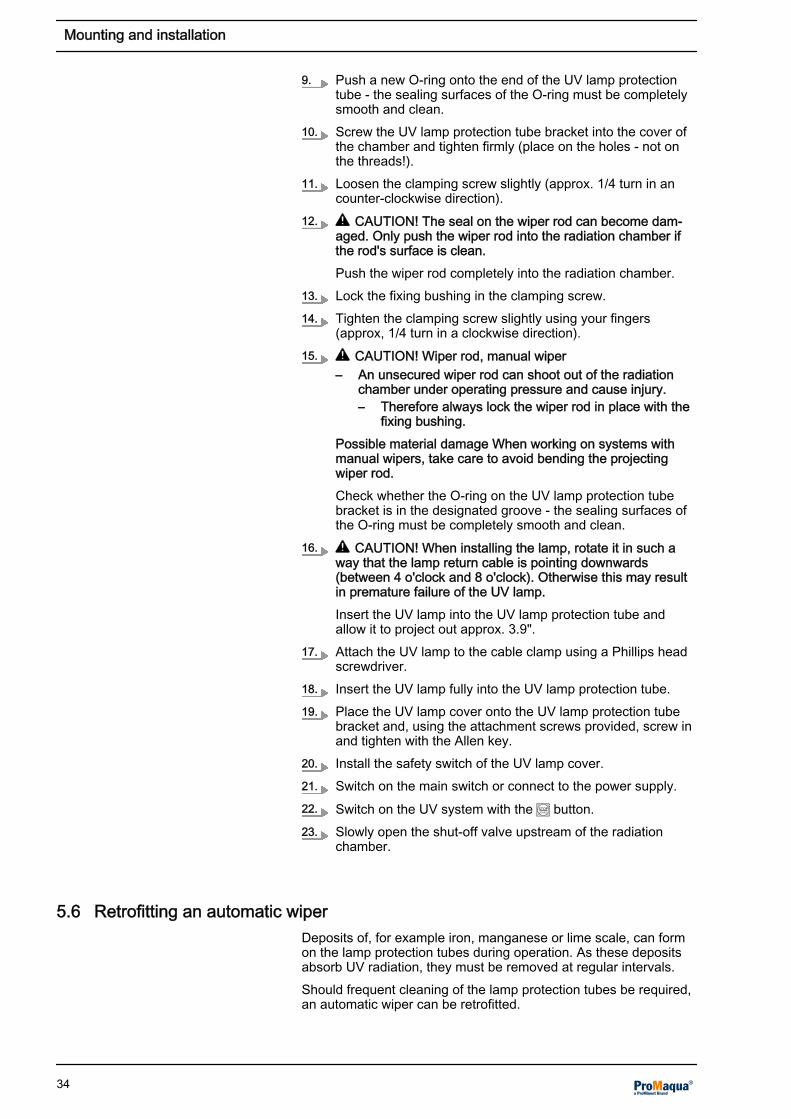
9. Push a new O-ring onto the end of the UV lamp protectiontube - the sealing surfaces of the O-ring must be completelysmooth and clean.
10. Screw the UV lamp protection tube bracket into the cover ofthe chamber and tighten firmly (place on the holes - not onthe threads!).
11. Loosen the clamping screw slightly (approx. 1/4 turn in ancounter-clockwise direction).
12. L CAUTION! The seal on the wiper rod can become dam‐aged. Only push the wiper rod into the radiation chamber ifthe rod's surface is clean.Push the wiper rod completely into the radiation chamber.
13. Lock the fixing bushing in the clamping screw.14. Tighten the clamping screw slightly using your fingers
(approx, 1/4 turn in a clockwise direction).15. L CAUTION! Wiper rod, manual wiper
– An unsecured wiper rod can shoot out of the radiationchamber under operating pressure and cause injury.– Therefore always lock the wiper rod in place with the
fixing bushing.Possible material damage When working on systems withmanual wipers, take care to avoid bending the projectingwiper rod.Check whether the O-ring on the UV lamp protection tubebracket is in the designated groove - the sealing surfaces ofthe O-ring must be completely smooth and clean.
16. L CAUTION! When installing the lamp, rotate it in such away that the lamp return cable is pointing downwards(between 4 o'clock and 8 o'clock). Otherwise this may resultin premature failure of the UV lamp.Insert the UV lamp into the UV lamp protection tube andallow it to project out approx. 3.9".
17. Attach the UV lamp to the cable clamp using a Phillips headscrewdriver.
18. Insert the UV lamp fully into the UV lamp protection tube.19. Place the UV lamp cover onto the UV lamp protection tube
bracket and, using the attachment screws provided, screw inand tighten with the Allen key.
20. Install the safety switch of the UV lamp cover.21. Switch on the main switch or connect to the power supply.22. Switch on the UV system with the STOP
START button.23. Slowly open the shut-off valve upstream of the radiation
chamber.
5.6 Retrofitting an automatic wiper
Deposits of, for example iron, manganese or lime scale, can formon the lamp protection tubes during operation. As these depositsabsorb UV radiation, they must be removed at regular intervals.Should frequent cleaning of the lamp protection tubes be required,an automatic wiper can be retrofitted.
Mounting and installation
34

For this purpose, the following retrofitting set is required: Automaticwiper
Material number UV system type
on request Dulcodes 1x1 S
on request Dulcodes 1x2 S
on request Dulcodes 1x3 S
on request Dulcodes 2x2 S
on request Dulcodes 2x3 S
on request Dulcodes 3x3 S
5.6.1 Removing the UV lamp protection tube with automatic wiper
Live parts!– Measure: The device must be disconnected from the power
supply before it is opened.– Disconnect damaged, defective or manipulated devices from
the power supply.– Do not modify the fitted UV lamp connection cable without
authorization.Possible consequence: Fatal or very serious injuries
UV-C radiation is harmful to the eyes and skin.– Only start up the UV lamps UV-C when they are properly installed.– Prior to commissioning, install the UV lamp into the UV system
in accordance with the instructions.Consequence: Serious injuriesFingerprints on the UV lamp– Only touch the glass of the UV lamp with cotton gloves.– Fingerprints or impurities burn into the glass and can result in
premature failure.– For this reason always clean the lamp thoroughly with a cloth
moistened with alcohol before installing.– Then wipe the UV lamp with a soft cloth.– Also thoroughly clean the glass of the UV lamp return cable.Possible consequence: Premature failure of the UV lampSafety switch for the UV lamp coverThe UV lamp cover is protected by a safety switch. The safetyswitch has a reed switch and comprises two components. Thesafety switch ensures that the UV lamp only generates UV radia‐tion when the switch is installed. If the safety switch is removed,the UV lamp switches off. If the safety switch is not installed andthus remains closed, e.g. after installation and maintenance work,the UV lamp cannot be started.1. Close the shut-off valves upstream and downstream of the
radiation chamber.2. Switch off the UV disinfection system with the STOP
START button.3. Switch off the main switch or disconnect from the power
supply.4. Drain the radiation chamber.5. Remove the safety switch of the UV lamp cover.
L WARNING
L WARNING
L CAUTION
Mounting and installation
35

6. Loosen the attachment screws of the lamp cover using anAllen key and remove the lamp cover and the lamp.
7. Put the UV lamp cover and the UV lamp aside completely.8. Using a face spanner, loosen the UV lamp protection tube
bracket and remove it (place on the holes - not on thethreads).
9. Carefully remove the UV lamp protection tube completelyfrom the radiation chamber and place on a suitable clean sur‐face.
10. Remove the O-ring from the lamp protection tube.11. Wash the UV lamp protection tube with cleaning solution or
immerse it in cleaning solution until the film has beenremoved without leaving a trace.
12. Rinse the UV lamp protection tube with clean water and drythoroughly with a soft cloth.
13. Carefully push the UV lamp protection tube into the radiationchamber until it reaches its stop position.
14. Push a new O-ring onto the end of the UV lamp protectiontube - the sealing surfaces of the O-ring must be smooth andclean.
15. Loosen the attachment screws on the cover of the chamber.16. Remove the cover of the chamber.
Mounting and installation
36

5.6.2 Assembly and installation of the automatic wiper
1.
2.
3.4.
5.
6.
7.
8.
9.
A0629
Fig. 20: Assembly and installation of the automatic wiper1. Grease the X-ring (1) on the inside diameter using
Carbaflo 2371 (TN1026526) and insert it into the cover (2).2. Screw the bearing cover (3) onto the chamber cover (2)
using the screws (4).3. Push the O-ring (5) onto the spacer rod (6).4. Press the spacer rod (6) into the chamber cover (2) and
screw it in with the fastening set (7).5. Push the wiper rod (8) through the chamber cover (2) into the
bearing cover (3).6. Secure the wiper rod (8) with the safety collar/supporting
washer (9).
Mounting and installation
37

A0630
6.
10.
7. Push the bracket (10) onto the opposing spacer rod (6), sothat the wiper cannot tilt.
A0632
11. 6.
12.13.
8. Push the support plate (11) with the slide bearing to the frontonto the threaded rod.
9. Screw the support plate (11) on to the spacer rods (6) usingthe fastening set (12).
10. Clip the bearing ring (13) centrally on the support plate (11)
Mounting and installation
38

16.
2.
14.
15.
17.
8.
18.
A0633
11. Screw the distance pin (14) into the chamber cover (2).12. Screw the adapter plate (15) with the hexagon screws/lock
washer onto the distance pin (14).13. Push the hexagon sleeve (16) onto the hexagon axle of the
wiper rod (8).14. Screw the actuator drive motor (17) to the adapter plate (15)
using the fastening set (18).
Mounting and installation
39

Place the fitted wiper unit on a support so that now the end posi‐tion of the wiper when operated by the actuator motor can bedefined.
A0634
Fig. 21: Adjustment instructions end stop (all dimensions in "mm")15. Now adjust the end position of the wiper. This is described in
the adjustment instructions of the actuator motor. Adjust thewiper so that the wiper stops 0.4" or 0.2" in front of the stopsas shown in Fig. 21.
L CAUTION! Inspect the UV lamp protection tube for damage.– You must not refit a damaged UV lamp protection tube.– Ensure that the UV lamp protection tube is seated correctly.
– The UV lamp protection tube may not project by more than0.5" and must not be offset at an angle.
16. Carefully push the UV lamp protection tube into the radiationchamber until it reaches its stop position.
17. Push a new O-ring onto the end of the UV lamp protectiontube.
ð The sealing surfaces of the O-ring must be completelysmooth and clean.
Place on the holes and not on the threads.18. Screw the UV lamp protection tube bracket into the chamber
cover and tighten the screws.19. Condition of the O-rings Check whether the O-ring on the
UV lamp protection tube bracket is seated in the designatedgroove. The sealing surfaces of the O-ring must be com‐pletely smooth and clean.Insert the UV lamp into the UV lamp protection tube.
ð The UV lamp must project approx. 3.9".
20. Secure the the UV lamp to the cable clamp using a Phillipsscrewdriver.
21. Completely insert the UV lamp into the UV lamp protectiontube.
22. Place the UV lamp cover onto the UV lamp protection tubebracket.
23. Screw the UV lamp cover onto the bracket using an Allenkey.
24. Install the safety switch of the UV lamp cover.
Mounting and installation
40

17.
19.
A0635
25. Push the the protective cover (19) in the longitudinal directionup to the end position over the actuator motor (17).
26. Switch the main switch on, or insert the plug in a power outlet27. Switch the UV system on using the STOP/START button.28. Slowly open the shut-off valves upstream and downstream of
the radiation chamber.
Mounting and installation
41

6 Commissioning
6.1 Leak testing and ventilation of the radiation chamber
Using your fingers, tighten the clamping screw on the wiper rod justuntil water stops leaking under operating pressure.1. Open the air vent on the radiation chamber.2. Slowly open the shut-off valve upstream of the radiation
chamber.3. Fill the radiation chamber until water emerges from the vent
screw.4. Close the air vent screw - this takes very little effort.5. Check that the radiation chamber is not leaking.6. Open the shut-off valve downstream from the radiation
chamber (only necessary with a manual shut-off valve).
6.2 Switching on the UV system
Only switch on the UV system after the radiation chamber hasbeen filled with water.The power of system types Dulcodes 1x2 S to 3x3 S can be man‐ually controlled in three steps by a step switch.Setting the stepsn Step 1: 50% of the stated rated power in kWn Step 2: 75% of the stated rated power in kWn Step 3: 100% of the stated rated power in kWSetting the power output allows the system to be adjusted to theload of the pool. If the chloramine contamination is low then thesystem power can be reduced.1. Switch the main switch on.2. Check the control parameters in programing mode. If neces‐
sary, change them.3. NOTICE! Ensure that the UV lamp is started at maximum
output. Set the manual step switch to the maximum UV lampoutput (100%).Switch the UV system on using the STOP
START key, keep the STOPSTART key
pressed down for at least 2 seconds.4. Should the control go into PAUSE mode, activate the Pause
contact.
ð Once the lamp has ignited, it will take approx. 1 - 3minutes until the full UV output has been reached.
L CAUTION
Commissioning
42

6.3 Calibrating the UV sensor
Insufficient treatment– Only a correctly calibrated UV sensor will guarantee adequate
treatment.– Water must be flowing through the radiation chamber when
calibrating the UV sensor.– The UV sensor must always be calibrated with new UV emit‐
ters.– The UV lamp must be operated at maximum output when cali‐
brating the UV sensor.Possible consequence: IllnessSafety and warning thresholds are no longer monitored during cali‐bration. For safety reasons, calibration is automatically interruptedafter 5 minutes without the changes made being saved. The timecount down can be seen in the display.The UV sensor signal must be stable before the start of calibration.A changing UV sensor signal shows that the UV lamp has not yetwarmed up sufficiently (5 to 10 minutes).
6.3.1 UV Sensor calibration
1. Press the key to go to the SENSOR CALIBRATION dis‐play.
2. Confirm with the key; REQUEST ACCESS CODE willappear on the display.
3. Enter the access code and confirm with the key.
ð SENSOR CALIBRATION re-appears. Adjustable valuesare flashing.
4. Using the and keys to adjust the UV sensor value to100%.
5. Confirm by pressing key.
ð The message "Saving data" appears briefly. The UVsensor is now calibrated.
6. Use the key to exit the programing mode.
ð The Dulcodes UV disinfection system is now ready foroperation.
L WARNING
Calibration
Commissioning
43
7 Maintenance
UV-C radiationUV-C radiation is harmful to the eyes and skin.– Only operate the UV lamp UV-C when it is fully installed.– Install the UV lamp into the UV system in accordance with the
regulations prior to commissioning.Possible consequence: Serious injuriesLive parts!– Measure: The device must be disconnected from the power
supply before it is opened.– Disconnect damaged, defective or manipulated devices from
the power supply.Possible consequence: Fatal or very serious injuriesGeneral safety measuresDepressurize the radiation chamber before commencing any main‐tenance work. Dirty filter mats on the fan and air outlet filter canlead to the control cabinet overheating and becoming damaged.Maximum permissible service lifehe UV lamps should be replaced at the latest after their maximumpermissible service life. Otherwise, the operating safety of the UVsystem is no longer warranted. The maximum permissible servicelife is 8,000 operating hours, unless otherwise stated in theenclosed data sheet.Safety switch for the UV lamp coverThe UV lamp cover is protected by a safety switch. The safetyswitch has a reed switch and comprises two components. Thesafety switch ensures that the UV lamp only generates UV radia‐tion when the switch is installed. If the safety switch is removed,the UV lamp switches off. If the safety switch is not installed andthus remains closed, e.g. after installation and maintenance work,the UV lamp cannot be started.The maintenance of the UV system is limited to cleaning the UVlamp protection tube and the sensor window as well as thereplacement of the UV lamp at the end of its maximum permissiblelife time. On systems with manual wipers, the wiper element andthe O-ring of the clamping screw must also be replaced.On systems, which have a fan in the switch cabinet, the filter matsof the fan and the air outlet filter on the switch cabinet must bereplaced regularly (normally once per year). An operating logshould be kept as a record; a form is included in the Appendix.
L WARNING
L WARNING
L CAUTION
NOTICE
Maintenance
44

7.1 Cleaning
7.1.1 Cleaning the UV lamp protection tube
Unsuitable cleaning agents– Do not use corrosive acids or acids that could cause stress
cracks, such as hydrochloric acid.– Read the safety data sheet for the cleaning agent selected.– Wear protective clothing when cleaning (protective eye wear,
protective gloves, etc.).– Ensure that no cleaning solution will penetrate the lamp protec‐
tion tube.– Ensure, when cleaning UV systems that no cleaning solution
will enter the piping.Possible bodily injury / material damage to the UV systemsCleaning timeClean the tube at the very latest when the UV sensor signal fallsbelow the warning threshold, without this being based on othercauses, such as aging of the UV lamp or significant deterioration ofthe UV transmission.Disposal of cleaning agentPossible environmental hazard Dispose of the waste cleaning solu‐tion in accordance with the pertinent guidelines and regulations.Deposits of, for example iron, manganese or lime scale, can formon the UV lamp protection tubes during operation. As thesedeposits absorb UV radiation, they must be removed at regularintervals.Annual cleaning of the UV lamp protection tubes when replacingthe UV lamp suffices for many UV systems. Clean more frequentlywhen operating with types of water that have a tendency tobecome dirty. The UV lamp protection tubes can be cleaned man‐ually when dismantled or can be cleaned by filling the radiationchamber with a cleaning solution. Acids, such as diluted phos‐phoric acid, acetic acid or diluted nitric acid, are particularly suit‐able for cleaning.Cleaning agents for manual cleaningIn spite of cleaning with a wiper, we recommend manual cleaningusing cleaning solution, when you remove the UV lamp protectiontube within the scope of UV lamp replacement.On systems, which are fitted with manual wipers, the UV lamp pro‐tection tubes can be cleaned while still installed using the manualwiper.In UV systems with automatic wipers, cleaning of the lamp protec‐tion tube while fitted is carried out every 2 years, dependent on theset wiper interval (presetting 2 h).
7.1.2 Cleaning with a manual wiper
Wiper rod, manual wiper– An unsecured wiper rod can shoot out of the radiation chamber
under operating pressure and cause injury.– Therefore always lock the wiper rod in place with the fixing
bushing.Possible material damage and slight bodily injury When working onUV systems with manual wipers, take care to avoid bending theprojecting wiper rod.
L CAUTION
NOTICE
NOTICE
L CAUTION
Maintenance
45

A0106
Fig. 22: Components of the manual wiper on the chamber coverand lamp connection1 Mushroom knob2 Guide bolt3 Fixing bushing4 Clamping screw5 Wiper rod6 O-ring7 Chamber cover8 Lamp protection tube9 O-ring10 Lamp protection tube bracket11 O-ring12 Cable clamp1. Loosen the clamping screw slightly (approx. 1/4 turn in an
counter-clockwise direction).2. Secure the handle to prevent it from thrusting backwards.3. Loosen the fixing bushing from the locked position of the
clamping screw.4. Pull or slide the wiper rod out of the radiation chamber until it
reaches its stop position.5. L CAUTION! The seal on the wiper rod can become dam‐
aged. Possible consequence: Leakage Only push the wiperrod with a clean surface into the radiation chamber.Push the wiper rod completely into the radiation chamber.
6. Repeat the wiping process as often as is necessary until thedisplay of the UV intensity on the control indicates a suffi‐ciently high value.
7. Push the wiper rod completely into the radiation chamber.8. Lock the fixing bushing in the clamping screw.9. Tighten the clamping screw slightly using your fingers
(approx, 1/4 turn in a clockwise direction).10. Flush the dissolved dirt and impurities out of the radiation
chamber with clean water (flushing connections).11. Connect the radiation chamber hydraulically to the complete
system (shut-off valves).
Cleaning with a manual wiper
Maintenance
46

7.1.3 Cleaning after dismantling the UV lamp protection tube
For systems without manual wipers, the irrelevant points can beskipped.UV-C radiationUV-C radiation is harmful to the eyes and skin.– Only start up the UV lamps UV-C when they are properly installed.– Install the UV lamp into the UV system in accordance with the
regulations prior to commissioning.Possible consequence: Serious injuriesLive parts!– Measure: The device must be disconnected from the power
supply before it is opened.– Disconnect damaged, defective or manipulated devices from
the power supply.Possible consequence: Fatal or very serious injuriesWiper rod, manual wiper– An unsecured wiper rod can shoot out of the radiation chamber
under operating pressure and cause injury.– Therefore always lock the wiper rod in place with the fixing
bushing.Possible material damage When working on systems with manualwipers, take care to avoid bending the projecting wiper rod.Fingerprints on the UV lamp– Only touch the glass of the UV lamp with cotton gloves.– Fingerprints or impurities burn into the glass and can result in
premature failure.– For this reason always clean the lamp thoroughly with a cloth
moistened with alcohol before installing.– Then wipe the UV lamp with a soft cloth.– Also thoroughly clean the glass of the UV lamp return cable.Possible consequence: Premature failure of the UV lampCleaning the UV SensorEvery time you clean the UV lamp protection tube, also clean theUV sensor.Safety switch for the UV lamp coverThe UV lamp cover is protected by a safety switch. The safetyswitch has a reed switch and comprises two components. Thesafety switch ensures that the UV lamp only generates UV radia‐tion when the switch is installed. If the safety switch is removed,the UV lamp switches off. If the safety switch is not installed andthus remains closed, e.g. after installation and maintenance work,the UV lamp cannot be started.1. Close the shut-off valves upstream and downstream of the
radiation chamber.2. Switch off the UV system with the STOP
START button.3. Switch off the main switch or disconnect from the power
supply.4. Drain the radiation chamber.5. Remove the safety switch of the UV lamp cover.6. Loosen the attachment screws of the lamp cover using an
Allen key and remove the lamp cover and the lamp.7. Put the UV lamp cover and the UV lamp aside completely.
L WARNING
L WARNING
L CAUTION
L CAUTION
Cleaning after dismantling the UVlamp protection tube
Maintenance
47

8. Loosen the clamping screw slightly (approx. 1/4 turn in ancounter-clockwise direction).
9. Loosen the fixing bushing from the locked position of theclamping screw.
10. Pull the wiper rod out to its stop position - it must remain in itsstop position until it is pushed in again.
11. Tighten the clamping screw slightly using your fingers(approx, 1/4 turn in a clockwise direction).
12. Using a face spanner wrench, loosen the UV lamp protectiontube bracket and remove it (place on the holes - not on thethreads).
13. Carefully remove the UV lamp protection tube completelyfrom the radiation chamber and place on a suitable clean sur‐face.
14. Remove the O-ring from the lamp protection tube.15. Wash the UV lamp protection tube with cleaning solution or
immerse it in cleaning solution until the film has beenremoved without leaving a trace.
16. Rinse the UV lamp protection tube with clean water and drythoroughly with a soft cloth.
17. Carefully push the UV lamp protection tube into the radiationchamber until it reaches its stop position.
18. Push a new O-ring onto the end of the UV lamp protectiontube - the sealing surfaces of the O-ring must be smooth andclean.
19. L CAUTION! Check the UV lamp protection tube fordamage before fitting.– A damaged UV lamp protection tube must not be refitted.– Ensure that the lamp protection tube is seated correctly.
– The UV lamp protection tube may not project by morethan 0.5" and must not be offset at an angle.
Screw the UV lamp protection tube bracket into the cover ofthe chamber and tighten firmly (place on the drill holes - noton the threads!)
20. L CAUTION! The seal on the wiper rod can become dam‐aged. Only push the wiper rod into the radiation chamber ifthe rod's surface is clean.Loosen the clamping screw slightly (approx. 1/4 turn in ancounter-clockwise direction).
21. Push the wiper rod completely into the radiation chamber.22. Lock the fixing bushing in the clamping screw.23. Tighten the clamping screw slightly using your fingers
(approx, 1/4 turn in a clockwise direction).24. L CAUTION! Wiper rod, manual wiper
– An unsecured wiper rod can shoot out of the radiationchamber under operating pressure and cause injury.– Therefore always lock the wiper rod in place with the
fixing bushing.Possible material damage When working on systems withmanual wipers, take care to avoid bending the projectingwiper rod.Check whether the O-ring on the UV lamp protection tubebracket is in the designated groove - the sealing surfaces ofthe O-ring must be completely smooth and clean.
Maintenance
48
25. L CAUTION! When fitting the UV lamp, rotate it so that theUV lamp return cable is directed downwards. Otherwise thismay result in premature failure of the UV lamp.Insert the UV lamp into the UV lamp protection tube andallow it to project out approx. 3.9".
26. Attach the UV lamp to the cable clamp using a Phillips headscrewdriver.
27. Insert the UV lamp fully into the UV lamp protection tube.28. Place the UV lamp cover onto the UV lamp protection tube
bracket and, using the attachment screws provided, screw inand tighten with the Allen key.
29. Install the safety switch of the UV lamp cover.30. Attach the pin plug with the UV lamp connection cable to the
terminal on the UV lamp cover and fix in place with theknurled nut.
31. Switch on the main switch or connect to the power supply.32. Switch on the UV system using the STOP
START button.33. Slowly open the shut-off valve upstream of the radiation
chamber.34. Open the shut-off valve downstream of the radiation chamber
(only necessary with a manual shut-off valve).
7.1.4 Cleaning with a cleaning solution
Handling the cleaning solution– It is also recommended with radiation chambers, which are
regularly cleaned by filling them with a cleaning solution, thatthe water drain and vent screws are replaced with suitablevalves.
– With larger radiation chambers, it is recommended that theyare filled through the water drain opening using an appropriateacid-resistant pump.
– If the radiation chamber is filled with a pump, it is also useful tocirculate the cleaning solution through the air vent opening.– This will shorten the cleaning time and achieve better
results.– If the cleaning solution is collected and stored in a suitable
storage tank, it can be reused several times.1. Switch off the UV system using the STOP
START button.2. Switch off the main switch or disconnect from the power
supply.3. Close the shut-off valves upstream and downstream of the
radiation chamber.4. Drain the radiation chamber5. Screw in the water drain screw again and tighten; this
requires very little effort.6. Fill the radiation chamber with the cleaning solution through
the vent opening.
ð Allow the cleaning solution to work for at least 20minutes.
7. Open and remove the water drain screw.
NOTICE
Cleaning the lamp protection tubes byfilling the radiation chamber with acleaning solution:
Maintenance
49

8. Drain the radiation chamber and dispose of the cleaning sol‐ution in accordance with the pertinent regulations.
9. Flush the radiation chamber thoroughly with clean water untilany cleaning solution residue has been removed.
10. Screw in the water drain screw and tighten; this requires verylittle effort.
11. Slowly open the shut-off valve upstream of the radiationchamber.
12. Fill the radiation chamber until water emerges from the ventscrew.
13. Close the air vent screw and tighten; this requires very littleeffort.
14. Open the shut-off valve downstream from the radiationchamber (only necessary with a manual shut-off valve).
ð Check that the radiation chamber is not leaking.
15. Switch on the main switch or connect to the power supply.
ð The UV system is again ready for operation.
7.1.5 Cleaning the UV Sensor
1. Loosen the sensor connection cable from the UV sensor.2. Twist the UV sensor out of the radiation chamber.3. Clean the quartz window with a cloth that has been saturated
with cleaning solution until the coating has been removedwithout leaving a trace.
4. Rinse the quartz window with clean water and dry with a softcloth.
5. Examine the O-ring for damage and replace any damagedseals.
6. Screw in the UV sensor again and tighten; this requires verylittle effort.
7. Connect the sensor connection cable to the UV sensor.8. Slowly open the shut-off valve upstream of the radiation
chamber.9. Fill the radiation chamber until water emerges from the vent
screw.10. Close the air vent screw and tighten; this requires very little
effort.11. Open the shut-off valve downstream from the radiation
chamber (only necessary with a manual shut-off valve).
ð Check that the radiation chamber is not leaking.
12. Switch on the main switch or connect to the power supply.
ð The UV system is again ready for operation.
Maintenance
50

7.2 Replacing the wiper elements (systems with manual wiper)
UV-C radiationUV-C radiation is harmful to the eyes and skin.– Only start up the UV lamps UV-C when they are properly installed.– Install the UV lamp into the UV system in accordance with the
regulations prior to commissioning.Possible consequence: Serious injuriesLive parts!– Measure: The device must be disconnected from the power
supply before it is opened.– Disconnect damaged, defective or manipulated devices from
the power supply.Possible consequence: Fatal or very serious injuriesWiper rod, manual wiper– An unsecured wiper rod can shoot out of the radiation chamber
under operating pressure and cause injury.– Therefore always lock the wiper rod in place with the fixing
bushing.Possible material damage and slight bodily injury When working onUV systems with manual wipers, take care to avoid bending theprojecting wiper rod.Fingerprints on the UV lamp– Only touch the glass of the UV lamp with cotton gloves.– Fingerprints or impurities burn into the glass and can result in
premature failure.– For this reason always clean the lamp thoroughly with a cloth
moistened with alcohol before installing.– Then wipe the UV lamp with a soft cloth.– Also thoroughly clean the glass of the UV lamp return cable.Possible consequence: Premature failure of the UV lamp1. Switch off the UV system using the STOP
START button.2. Switch off the main switch or disconnect from the power
supply.3. Close the shut-off valves upstream and downstream of the
radiation chamber.4. Drain the radiation chamber.5. Remove the safety switch of the UV lamp cover.6. Loosen the attachment screws of the UV lamp cover using
the enclosed Allen key and remove the lamp cover and theUV lamp.
7. Put the UV lamp cover and the UV lamp completely aside.8. Loosen the clamping screw slightly (approx. 1/4 turn in an
counter-clockwise direction).9. Loosen the fixing bushing from the locked position of the
clamping screw.10. Pull the wiper rod out to its stop position - it must remain in its
stop position until it is pushed in again.11. Tighten the clamping screw slightly using your fingers
(approx, 1/4 turn in a clockwise direction).
Maintenance interval: 1 - 2 years
L WARNING
L WARNING
L CAUTION
L CAUTION
Replacing the wiper elements
Maintenance
51

12. Using a face spanner wrench, loosen the UV lamp protectiontube bracket and remove it (place on the holes - not on thethreads).
13. Carefully remove the UV lamp protection tube completelyfrom the radiation chamber and place on a suitable clean sur‐face.
14. Remove the O-ring from the lamp protection tube.15. Wash the UV lamp protection tube with cleaning solution or
immerse it in cleaning solution until the film has beenremoved without leaving a trace.
16. Rinse the UV lamp protection tube with clean water and drythoroughly with a soft cloth.
17. Remove the screws of the cover of the radiation chamber.18. Carefully place the radiation chamber cover and the fully
removed wiper rod in a suitable, clean spot.19. Remove one hexagonal screw from a wiper.20. Remove the old wiper element from the side.21. Insert the new wiper element from the side - the wiping lip
must point away from the radiation chamber.22. Insert the Allen screw with the socket into the wiper and
tighten.23. NOTICE! The wiper element must sit loosely in the wiper
even when the Allen screw is tightened. If this is not thecase, eliminate the cause or use another wiper element.Fit a new O-ring to the cover of the radiation chamber.
24. Carefully insert the radiation chamber cover with the wiperrod still fully pulled out into the radiation chamber - the wiperrod must sit in its fixture on the radiation chamber cover andremain there until the lamp protection tube is fitted.
25. Screw the cover of the radiation chamber onto the radiationchamber so that it is moisture-proof.
26. Carefully push the UV lamp protection tube into the radiationchamber until it reaches its stop position.
27. Push a new O-ring onto the end of the UV lamp protectiontube - the sealing surfaces of the O-ring must be completelysmooth and clean.
28. L CAUTION! Check the UV lamp protection tube fordamage before fitting.– A damaged UV lamp protection tube must not be refitted.– Ensure that the lamp protection tube is seated correctly.
– The UV lamp protection tube may not project by morethan 0.5" and must not be offset at an angle.
Screw the UV lamp protection tube bracket into the cover ofthe chamber and tighten firmly (place on the drill holes - noton the threads!)
29. L CAUTION! The seal on the wiper rod can become dam‐aged. Only push the wiper rod into the radiation chamber ifthe rod's surface is clean.Loosen the clamping screw slightly (approx. 1/4 turn in ancounter-clockwise direction).
30. Push the wiper rod completely into the radiation chamber.31. Lock the fixing bushing in the clamping screw.
Maintenance
52

32. Tighten the clamping screw slightly using your fingers(approx, 1/4 turn in a clockwise direction).
33. L CAUTION! Wiper rod, manual wiper– An unsecured wiper rod can shoot out of the radiation
chamber under operating pressure and cause injury.– Therefore always lock the wiper rod in place with the
fixing bushing.Possible material damage When working on systems withmanual wipers, take care to avoid bending the projectingwiper rod.Check whether the O-ring on the UV lamp protection tubebracket is in the designated groove - the sealing surfaces ofthe O-ring must be completely smooth and clean.
34. L CAUTION! When fitting the UV lamp, rotate it so that theUV lamp return cable is directed downwards. Otherwise thismay result in premature failure of the UV lamp.Insert the UV lamp into the UV lamp protection tube andallow it to project out approx. 3.9".
35. Attach the UV lamp to the cable clamp using a Phillips headscrewdriver.
36. Insert the UV lamp fully into the UV lamp protection tube.37. Place the UV lamp cover onto the UV lamp protection tube
bracket and, using the attachment screws provided, screw inand tighten with an Allen key.
38. Install the safety switch of the UV lamp cover.39. Switch on the main switch or connect to the power supply.40. Switch on the UV system using the STOP
START button.41. Slowly open the shut-off valve upstream of the radiation
chamber.42. Open the shut-off valve downstream of the radiation chamber
(only necessary with a manual shut-off valve).
7.3 Replace the O-ring on the clamping screw.
Wiper rod, manual wiperPossible material damage and slight bodily injury When working onsystems with manual wipers, take care to avoid bending the projec‐ting wiper rod.
Maintenance interval: 1 year
L CAUTION
Maintenance
53

A0106
Fig. 23: Components of the manual wiper on the chamber coverand lamp connection1 Mushroom knob2 Guide bolt3 Fixing bushing4 Clamping screw5 Wiper rod6 O-ring7 Chamber cover8 Lamp protection tube9 O-ring10 Lamp protection tube bracket11 O-ring12 Cable clamp1. Depressurize the radiation chamber.2. Loosen the clamping screw slightly (approx. 1/4 turn in an
anti-clockwise direction).3. Loosen the fixing bushing from the locked position of the
clamping screw.4. Fully remove the wiper rod.5. Unscrew the mushroom handle from the wiper rod using an
SW 11 open-jaw wrench.6. Push the wiper rod approx. 5.9" into the radiation chamber.7. Remove the clamping screw.8. Pull the wiper rod fully out again - it will pull out the O-ring at
the same time.
ð Clean the wiper rod if required.
9. Replace the O-ring.10. Fit the clamping screw but do not tighten firmly.11. Screw the mushroom knob (with fixing bushing) onto the
wiper rod using an SW 11 open-jaw wrench.12. L CAUTION! The seal on the wiper rod can become dam‐
aged. Possible consequence: Leakage Only push the wiperrod with a clean surface into the radiation chamber.Push the wiper rod completely into the radiation chamber.
13. Lock the fixing bushing in the clamping screw.
Maintenance
54

14. Using your fingers, tighten the clamping screw on thewiper rod just until water stops leaking under operating pres‐sure.Tighten the clamping screw slightly using your fingers(approx, 1/4 turn in a clockwise direction).L CAUTION! Wiper rod, manual wiper– An unsecured wiper rod can shoot out of the radiation
chamber under operating pressure and cause injury.– Therefore always lock the wiper rod in place with the
fixing bushing.Possible material damage and slight bodily injury Whenworking on UV systems with manual wipers, take care toavoid bending the projecting wiper rod.
7.4 Maintenance of the automatic wiper
A0609
Fig. 24: Spare parts kit TN1037735You must replace these components after an operating period ofone year.
7.4.1 Replacing the wiper elements (UV systems with automatic wiper)
UV-C radiationUV-C radiation is harmful to the eyes and skin.– Only start up the UV lamps UV-C when they are properly installed.– Install the UV lamp into the UV system in accordance with the
regulations prior to commissioning.Possible consequence: Serious injuries
Maintenance interval: 1 year
Maintenance interval: 1 year
L WARNING
Maintenance
55

Live parts!– Measure: The device must be disconnected from the power
supply before it is opened.– Disconnect damaged, defective or manipulated devices from
the power supply.Possible consequence: Fatal or very serious injuriesFingerprints on the UV lamp– Only touch the glass of the UV lamp with cotton gloves.– Fingerprints or impurities burn into the glass and can result in
premature failure.– For this reason always clean the lamp thoroughly with a cloth
moistened with alcohol before installing.– Then wipe the UV lamp with a soft cloth.– Also thoroughly clean the glass of the UV lamp return cable.Possible consequence: Premature failure of the UV lampSafety switch for the UV lamp coverThe UV lamp cover is protected by a safety switch. The safetyswitch has a reed switch and comprises two components. Thesafety switch ensures that the UV lamp only generates UV radia‐tion when the switch is installed. If the safety switch is removed,the UV lamp switches off. If the safety switch is not installed andthus remains closed, e.g. after installation and maintenance work,the UV lamp cannot be started.1. Switch off the UV system using the STOP
START button.2. Switch off the main switch or disconnect from the power
supply.3. Close the shut-off valves upstream and downstream of the
radiation chamber.4. Drain the radiation chamber.5. Remove the safety switch of the UV lamp cover.6. Loosen the attachment screws of the UV lamp cover using
the enclosed Allen key and remove the lamp cover and theUV lamp.
7. Put the UV lamp cover and the UV lamp completely aside.8. Pull off the protective cover over the motor in the longitudinal
direction9. Using a face spanner wrench, loosen the UV lamp protection
tube bracket and remove it (place on the holes - not on thethreads).
10. Carefully remove the UV lamp protection tube completelyfrom the radiation chamber and place on a suitable clean sur‐face.
11. Remove the O-ring from the lamp protection tube.12. Wash the UV lamp protection tube with cleaning solution or
immerse it in cleaning solution until the film has beenremoved without leaving a trace.
13. Rinse the UV lamp protection tube with clean water and drythoroughly with a soft cloth.
14. Remove the screws of the cover of the radiation chamber.15. Carefully lay the radiation chamber cover and the wiper unit
in a suitable, clean place.16. Remove one hexagonal screw from a wiper.
L WARNING
L CAUTION
Replace the wiper elements.
Maintenance
56

1.
A0631
Fig. 25: Wiper element17. Remove the old wiper element (1) from the side.18. Insert the new wiper element (1) from the side - the wiping lip
must point away from the radiation chamber.19. Insert the Allen screw with the socket into the wiper and
tighten.20. NOTICE! The wiper element must sit loosely in the wiper
even when the Allen screw is tightened. If this is not thecase, eliminate the cause or use another wiper element.Fit a new O-ring to the cover of the radiation chamber.
21. Carefully insert the radiation chamber cover with the wiperunit into the radiation chamber.
22. Screw the cover of the radiation chamber onto the radiationchamber so that it is moisture-proof.
23. Carefully push the UV lamp protection tube into the radiationchamber until it reaches its stop position.
24. Push a new O-ring onto the end of the UV lamp protectiontube - the sealing surfaces of the O-ring must be completelysmooth and clean.
25. L CAUTION! Check the UV lamp protection tube fordamage before fitting.– A damaged UV lamp protection tube must not be refitted.– Ensure that the lamp protection tube is seated correctly.
– The UV lamp protection tube may not project by morethan 0.5" and must not be offset at an angle.
Screw the UV lamp protection tube bracket into the cover ofthe chamber and tighten firmly (place on the drill holes - noton the threads!)
26. Insert the UV lamp with the cable clamp fully into the UVlamp protection tube.
Maintenance
57

27. Place the UV lamp cover onto the UV lamp protection tubebracket and, using the attachment screws provided, screw inand tighten with an Allen key.
28. Install the safety switch of the UV lamp cover.29. Push the protective cover in the longitudinal direction over
the motor up to the end position.30. Switch on the main switch or connect to the power supply.31. Switch on the UV system using the STOP
START button.32. Slowly open the shut-off valve upstream of the radiation
chamber.33. Open the shut-off valve downstream of the radiation chamber
(only necessary with a manual shut-off valve).
7.5 Replacing the lamp
Live parts!– Measure: The device must be disconnected from the power
supply before it is opened.– Disconnect damaged, defective or manipulated devices from
the power supply.Possible consequence: Fatal or very serious injuriesUV-C radiationUV-C radiation is harmful to the eyes and skin.– Only start up the UV lamps UV-C when they are properly installed.– Install the UV lamp into the UV system in accordance with the
regulations prior to commissioning.Possible consequence: Serious injuriesInsufficient treatment efficiency– The UV lamps must be replaced with new lamps as soon as:
– The sensor signal approaches the minimum safetythreshold unless traced back to another cause, such as for‐mation of a coating on the lamp protection tubes or aserious deterioration of the UV transmission;
– The operating life of the UV lamp is approaching or hasexceeded its maximum service life.
Possible consequence: Illness Please read the Technical DataSheet enclosed with the respective UV system.Fingerprints on the UV lamp– Only touch the glass of the UV lamp with cotton gloves.– Fingerprints or impurities burn into the glass and can result in
premature failure.– For this reason always clean the lamp thoroughly with a cloth
moistened with alcohol before installing.– Then wipe the UV lamp with a soft cloth.– Also thoroughly clean the glass of the UV lamp return cable.Possible consequence: Premature failure of the UV lampClean the lamp protection tubes each time a lamp is replaced. Dis‐pose of used lamps in accordance with the applicable guidelinesand directives. Usually these can be disposed of together withused fluorescent tubes.
L WARNING
L WARNING
L WARNING
L CAUTION
NOTICE
Maintenance
58

Safety switch for the UV lamp coverThe UV lamp cover is protected by a safety switch. The safetyswitch has a reed switch and comprises two components. Thesafety switch ensures that the UV lamp only generates UV radia‐tion when the switch is installed. If the safety switch is removed,the UV lamp switches off. If the safety switch is not installed andthus remains closed, e.g. after installation and maintenance work,the UV lamp cannot be started.1. Switch off the UV system using the STOP
START button.2. Switch off the main switch or disconnect from the power
supply.3. Close the shut-off valves upstream and downstream of the
radiation chamber.4. Remove the safety switch of the UV lamp cover.5. Loosen the attachment screws of the lamp cover using an
Allen key, remove the lamp cover and pull out the lamp byapproximately 3.9".
6. Loosen the UV lamp at the cable clamp using a Phillips headscrewdriver.
7. Fully remove the UV lamp and lay it aside.8. Check whether the O-ring on the UV lamp protection tube
bracket is in the designated groove - the sealing surfaces ofthe O-ring must be completely smooth and clean.
9. L CAUTION! When fitting the UV lamp, rotate it so that theUV lamp return cable is directed downwards. Otherwise thismay result in premature failure of the UV lamp.Insert the UV lamp into the UV lamp protection tube andallow it to project out approx. 3.9".
10. Attach the UV lamp to the cable clamp using a Phillips headscrewdriver.
11. Insert the UV lamp fully into the UV lamp protection tube.12. Place the UV lamp cover onto the UV lamp protection tube
bracket and, using the attachment screws provided, screw inand tighten with an Allen key.
13. Install the safety switch of the UV lamp cover.14. Switch on the main switch or connect to the power supply.15. Switch on the UV system with the STOP
START button.16. Slowly open the shut-off valve upstream of the radiation
chamber.17. Open the shut-off valve downstream of the radiation chamber
(only necessary with a manual shut-off valve).
Insufficient treatment efficiencyPossible consequence: Death or illness Check safety and warningthreshold. Check and possibly reset the safety and warningthreshold when the UV lamp is replaced. Only a correctly adjustedsafety threshold will guarantee adequate treatment.1. With the system switched off, use the key to display the
UV lamp hours and UV lamp connections.2. Confirm using the key - the "Request Access Code" dis‐
play will appear.3. Enter the access code and confirm with the key - the
"Reset" display will appear.
L WARNING
Reset UV lamp hours and UV lampconnections.
Maintenance
59

4. Confirm with the key - the display will now be reset.
7.6 Calibrating the UV sensor
Calibrate the UV-C sensor compliant to the specifications, seeÄ Chapter 6.3 “Calibrating the UV sensor” on page 43
7.7 Replacing the filter mats
General safety measuresDirty filter mats on the fan and air outlet filter can lead to the controlcabinet overheating and becoming damaged.Replace the filter mats on the fan and the air outlet filter at leastonce per year. The filter mats must be replaced at shorter intervalsin unfavorable ambient conditions.1. Switch off the UV system using the STOP
START button.2. Switch off the main switch3. Remove the cover of the fan. To do so, insert your fingers
into the recesses on the bottom of the cover and remove thecover
4. Remove the dirty filter mat and insert a new filter mat with thewhite side facing inwards (control cabinet side).
5. Replace the filter mat on the air outlet filter as describedabove
6. Switch on the main switch.
Replacement of the filter mats on thefan and the air outlet filter
L CAUTION
Maintenance
60

8 Troubleshooting
Live parts!– Measure: The device must be disconnected from the power
supply before it is opened.– Disconnect damaged, defective or manipulated devices from
the power supply.– Troubleshooting on the open control cabinet and the replace‐
ment of components may only be done by an authorized elec‐trician.
Possible consequence: Fatal or very serious injuries
After acknowledging the fault messageIf you have acknowledged a fault, the UV system will switch fromthe [Fault] state to the [Off] state. Before starting the UV system,you must check whether possibly implemented troubleshootingmeasures were successful. Only after clearing all fault-relatederrors does a new start make sense.
Fault alert* Possible cause Remedy
Warning thresholdtransgressedMessage: DownarrowSafety thresholdtransgressedMessage: UVsensor
Lamp output too low Increase lampoutput (using themanual rotary dialon systems withoutput control).
Coating formed onthe lamp protectiontube and/or the UVCsensor.
Clean lamp protec‐tion tube and UVCsensor.
Deterioration in theUV-transmission ofthe water to betreated.
Improve waterquality Possiblecause UV lamp atthe end of itsservice life
UV lamp at the endof its UV emissionservice life
Replace the UVsensor.
UV sensor not cali‐brated
Calibrating UVSensor, seeÄ Chapter 6.3 “Cali‐brating the UVsensor” on page 43
*Acknowledge the fault alert with the key.
L WARNING
↓ 55 %
20 On/Off10 h Operation
Fig. 26: Warning threshold trans‐gressed
Fault
UV sensor
Fig. 27: Safety threshold transgressed
Troubleshooting
61

Fault alert* Possible cause Remedy
Safety thresholdtransgressedMessage: Lampfault; UV sensor 0%
UV lamp defective Replace UV lamp.
Starters defective Replace starters.
*Acknowledge the fault alert with the key.
Fault alert* Possible cause Remedy
Message: Excesstemperature
Temperature switchdefective
Replace tempera‐ture switch.
Water flow rate toolow
Increase water flowrate.
*Acknowledge the fault alert with the key.
Display Possible cause Remedy
Flashing doublearrow during calibra‐tion
UV lamp protectiontube and/or UVsensor are dirty.
Clean UV lamp pro‐tection tube and/orUV sensor.
UV sensor defective Use a new UVsensor.
If a flashing double arrow appears in the calibration displayinstead of the sensor signal, the sensor signal is too weak forcorrect calibration. Calibration cannot be performed.
Fault alert* Possible cause Remedy
Message: Otherfaults
External fault signaldevice triggered
Eliminate cause ofexternal fault.
No external faultsignal device con‐nected and the con‐tacts at the faultinput are notbridged
Bridge contacts atfault input.
*Acknowledge the fault alert with the key.
Fault
Lamp faultUV sensor 0 %
Fig. 28: Safety threshold transgressed
Fault
Excess temperature
Fig. 29: Message: Excess tempera‐ture
Cal. factor =
Time 5:00
0,420
↓↓
Fig. 30: Flashing double arrow duringcalibration
Fault
Other Fault
Fig. 31: Message: Other faults
Fault
Memory error
Troubleshooting
62

Fault alert* Possible cause Remedy
Message: MemoryerrororMessage: Defaultsetting
During self-testing,the control hasdetected an error inthe memory.
Replace the control(only an electricianis authorized to doso).
*Acknowledge the fault alert with the key.
Fig. 32: Message: Memory error
Fault
Default setting
Fig. 33: Message: Default setting
Troubleshooting
63

9 Technical data
Data sheetThis technical data supplements the enclosed data sheet. If indoubt, the information on the data sheet applies.
Type Number of lamps Lamp output power input
1x1S 1 0.78 kW 0.90 kW
1x2S 1 2.00 kW 2.10 kW
1x3S 1 3.00 kW 3.20 kW
2x2S 2 4.00 kW 4.20 kW
2x3S 2 6.00 kW 6.20 kW
3x3S 3 9.00 kW 9.20 kW
Type Max. flow* ConnectorNominal width can be selected
1x1S 1,871.7 cubic feet/h 225 GPM DN 100/125 ANSI 4"
1x2S 3,143 cubic ft/h 392 GPM DN 125/150 ANSI 6"
1x3S 6,250.1cubic ft/h 779 GPM DN 200/250 ANSI 8"
2x2S 8,475.5 cubic ft/h 1057 GPM DN 200/250 ANSI 8"
2x3S 11,653.1 cubic ft/h 1453 GPM DN 250 ANSI 10"
3x3S 17,657.3 cubic ft/h 2202 GPM DN 250/300 ANSI 12"
* 98%/0.4" transmission; 600 J/10.8 square ft
Type Pressure loss at maximum flow Minimum clear‐ance forMaintenancework
Net weight /Operating weightRadiationchamber
Volume
1x1S 7 mbar 0.1 psi 15.76" 68.2 lbs. / 103.4lbs.
4.2 gal.
1x2S 6 mbar 0.1 psi 19.7" 83.6 lbs. / 143 lbs. 7.1 gal.
1x3S 4 mbar 0.05 psi 23.6" 114.4 lbs. / 259.6lbs.
17.4 gal.
2x2S 6 mbar 0.1 psi 39.4" 171.6 lbs. / 365.2lbs.
26.4 gal
2x3S 10 mbar 0.15 psi 39.4" 171.6 lbs. / 365.2lbs.
26.4 gal
3x3S 25 mbar 0.5 psi 39.4" 171.6 lbs. / 365.2lbs.
DN 250 = 26.4gal.
Performance data
NOTICE
Technical data
64

Permissible operating temperatures:n Water temperature: 5 ... 104.0°Fn Ambient temperature: 5 ... 104.0°FOperating pressure*The permissible operating pressure is possibly lower with systemsthat have a non-standard design,Requirements of the water to be treated:n Maximum temperature: 104.0°Fn Maximum operating pressure: 6 bar* //n No corrosive or abrasive properties, chloride content < 250
ppmn No tendency for sedimentation
9.1 Dimensions sheet
Fig. 34: Dulcodes 1 kW - 3 kW dimensions sheet (drawings not to scale) (all dimensions in "mm")
Typ 1x1 S DIN 1x1 S ANSI 1x2 S 1x3 S
D1 168,3 6.63" 219,1 323,9
L1 700,0 27.56" 700,0 800,0
Drawings not true to scale.(All dimensions in "mm")
Technical data
65
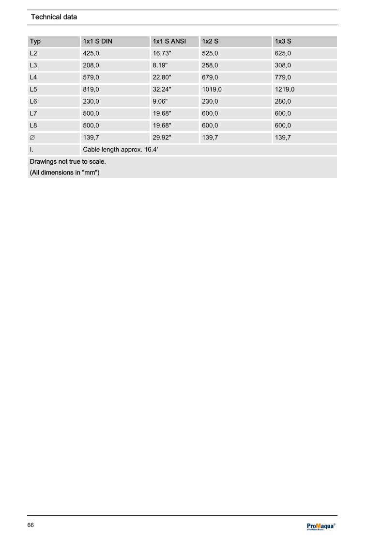
Typ 1x1 S DIN 1x1 S ANSI 1x2 S 1x3 S
L2 425,0 16.73" 525,0 625,0
L3 208,0 8.19" 258,0 308,0
L4 579,0 22.80" 679,0 779,0
L5 819,0 32.24" 1019,0 1219,0
L6 230,0 9.06" 230,0 280,0
L7 500,0 19.68" 600,0 600,0
L8 500,0 19.68" 600,0 600,0
Æ 139,7 29.92" 139,7 139,7
I. Cable length approx. 16.4'
Drawings not true to scale.(All dimensions in "mm")
Technical data
66

G 3/4" G 3/4"
G 3/4"G 3/4"
416 382900
382416
273Ø
636
692
951
600 300
1400
200
323,
9
345
Ø
A0560
Fig. 35: Dimensions sheet Dulcodes 2x2 kW, 2x3 kW, 3x3kW, multiple UV lamp systems (drawings not toscale) (all dimensions in "mm")
Type 2x2 kW 2x3 kW 3x3 kW
DN 200 250 250
DN 250 --- 300
9.2 Electrical data
FusesThe fuses are located in fuse boxes with a bayonet lock, on theright in the terminal box of the control.
Dimensions sheet Dulcodes 2x2 kW,2x3 kW, 3x3 kW, multiple UV lampsystems
NOTICE
Technical data
67

Type Voltage Frequency
1x1S 230 V AC 460 V AC* 50 Hz 60 Hz*
1x2S 400 V AC 480 V AC* 50/60 Hz 50/60 Hz*
1x3S 400 V AC 480 V AC* 50/60 Hz 50/60 Hz*
2x2S 400 V AC 480 V AC* 50/60 Hz 50/60 Hz*
2x3S 400 V AC 480 V AC* 50/60 Hz 50/60 Hz*
3x3S 400 V AC 480 V AC* 50/60 Hz 50/60 Hz*
* = Alternative power supply. Observe the supplied system circuit diagram.
Fuse Version Spare parts number
Upper fuse(self-supply by the control)
0.16 A slow 712048
Lower fuse(switched power outputs)(XR1-XR3)
2.50 A slow 712033
Control cabinetn Inputs
– Contact inputs (-X3:1 ... -X3.6):for contacts or switching transistors:Open circuit voltage: 5V ± 0.5 VInput resistance: 10 kOhm
n Outputs– Voltage outputs (-X1:1 ... -X1.10):
Type of contact: NOCLoad capacity: 250 V AC / 3 A / 100 VAWith inductive loads provide RC protection circuits
– Relay outputs (-X4:1 ... -X4.6):Type of contact: NOCLoad capacity: 250 V AC / 3 A / 100 VAWith inductive loads provide RC protection circuits
– Alarm relay (-X4:7 ... -X4.9):Type of contact: Changeover contactLoad capacity: 250 V AC / 3 A / 100 VAWith inductive loads provide RC protection circuits
– Standard signal output mA (-X3:7 ... -X3.8):0/4...20 mA, potential-freeMaximum load: 600 Ohm
Technical data
68

10 Appendix
10.1 Spare parts 1 kW - 3 kW single UV lamp system without wiper or manualwiper
120
130
113
114 101
141
120
311
312
310
301
153
153154
154132
161
102
104
105
115
150
316
320
340
P_PMA_DS_0012_SW
900
901
A
Fig. 36: Spare parts drawing Dulcodes S single UV lamp system with manual wiper
Appendix
69

Spare parts list 1 kW - 3 kW single UV lamp system without wiper or manual wiper
No. Description Spare partsnumber
Replacementinterval
each
101 UV lamp protection tubed1.6x0.1x15" Q, 1 kW
1035166 2 - 3 years 1
101 UV lamp protection tubed1.6x0.1x19" Q, 2 kW
1035041 2 - 3 years 1
101 UV lamp protection tubed1.6x0.1x22.9" Q, 3 kW
1035193 2 - 3 years 1
102 UV lamp 0.65 kW, 1 kW 1035179 max. 8,000 h 1
102 UV lamp 2 kW 1035057 max. 8,000 h 1
102 UV lamp 3 kW 1035180 max. 8,000 h 1
104 UV lamp protection tube bracket 1035059 on request 1
105 Retainer 1.9/1.5 x 0.12" PTFE white 1035074 on request 1
113 Temperature switch G 3/4 1035104 on request 1
114 Bearing ring D 2.1/1.6 x 0.5" PTFE 1035058 on request 1
120 Locking screw DIN 910 G 3/4 1002753 on request 1
130 UV sensor M G 3/4 1.4539 1034147 on request 1
132 UV sensor connection cable 32.8' 1028063 on request 1
141 O-ring 5.9" - 0.2" EPDM 1027463 after openingchamber
1
150 O-ring 1.6" - 0.2" EDDM 1023569 on request 2
153 O-ring/M 0.9" - 0.1" EPDM 1002175 on request 2
154 O-ring/M 1" - 0.08" EPDM 792872 on request 2
301 Turning mushroom knob GN 597-45-M10 1027877 on request
310 Guide bolt M0.3/M0.4x2.6" 1027931 on request 1
311 Complete clamping screwfor wiper rod
1027975 on request 1
312 Fixing bushing with pins 1027930 on request 1
316 O-ring 0.5" - 0.1" EPDM 790410 1 year 1
320 Complete bearing flangefor wiper rod
1024944 on request 1
340 Wiper rod compl. UVS 1KW 1035177 on request 1
340 Wiper rod compl. UVS 1KW 1035131 on request 1
340 Wiper rod compl. UVS 1KW 1035178 on request 1
860 Face spanner wrenchfor Æ 0.6" - 3.9"
409805 on request 1
900 Wiper element 1027879 1 - 2 years 1
901 Retaining ring d2.4"/1.8"x0.2" 1028100 on request 1
Appendix
70
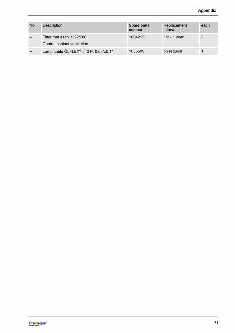
No. Description Spare partsnumber
Replacementinterval
each
-- Filter mat each 3322/700Control cabinet ventilation
1004212 1/2 - 1 year 2
-- Lamp cable ÖLFLEX® 540 P, 0.08"x0.1" 1035509 on request 1
Appendix
71

10.2 Spare parts 1 kW - 3 kW single UV lamp system with automatic wiper
120
130
153
114
101
140
141
A
117
120
153
113154
154
100145
B352
142143144
146
180181182 305
353
656
354
356
355 352
A0557
Fig. 37: Spare parts drawing Dulcodes S single UV lamp system with automatic wiper
Appendix
72

104
105
115
123
124
121
150
150
102
862
340
334183
316
324
318
122
186
152
333 /187
320
327
357
A
A ( I )
B
A0558
Fig. 38: Spare parts drawing Dulcodes S single UV lamp system with automatic wiper, detail "A" and "B"I. As supplied
Spare parts list 1 kW - 3 kW single UV lamp system with automatic wiper
No. Description Spare parts number Replacementinterval
each
90 Spare parts kit UVS 1 ... 3 kW 1037735 1 year 1
95 Installation tool for UVS motor bearing bush 1036907 on request 1
96 Installation tool for UVS motor threadedsleeve
1037738 on request 1
✱ = forms part of the spare parts kit UVS 1 - 3 kW (1037735)
Appendix
73

No. Description Spare parts number Replacementinterval
each
101 UV lamp protection tubed1.6x0.1x15" Q, 1 kW
1035166 2 - 3 years 1
101 UV lamp protection tubed1.6x0.1x19" Q, 2 kW
1035041 2 - 3 years 1
101 UV lamp protection tubed1.6x0.1x22.9" diameter, 3 kW
1035193 2 - 3 years 1
102 UV lamp 0.65 kW, 1 kW 1035179 max. 8,000 h 1
102 UV lamp 2 kW 1035057 max. 8,000 h 1
102 UV lamp 3 kW 1035180 max. 8,000 h 1
104 UV lamp protection tube bracket 1035059 on request 1
105 Retainer 1.9"/1.5" x 3 PTFE white 1035074 on request 1
113 Temperature switch G 3/4 1035104 on request 1
114 Bearing ring D 2.1"/1.6" x 12 PTFE 1035058 on request 1
115 Washer ⌀2.7" x 0.8" - M 0.6" x 0.06" 1035004 on request 1
120 Locking screw DIN 910 G 3/4 1002753 on request 1
121 Complete cable clamp, ⌀1.35" x 1.4" 1035011 on request 1
122✱
Safety collar DIN 471, 0.31" x 0.03" 467238 1 year 1
130 UV sensor M G 3/4 1.4539 1034147 on request 1
131 UV sensor connection cable 32.8' 1028063 on request 1
141 O-ring 5.9" - 0.2" EPDM 1027463 after openingchamber
1
150 O-ring 1.6A" - 0.2" EPDM 1023569 on request 2
152 O-ring/M 0.24" - 0.1" FPM-B 740331 on request 1
153 O-ring/M 0.9" - 0.1" EPDM 1002175 on request 2
154 O-ring/M 1" - 0.08" EPDM 792872 on request 2
316✱
X-ring 0.5 x 0.2x 0.2" 70 EPDM 281 1010384 1 year 1
320 Bearing cover complete UVS motor wiper 1037028 on request 1
340 Wiper rod complete UVS 2 kW automaticwiper
1037069 on request 1
340 Wiper rod complete UVS 3 kW automaticwiper
1037680 on request 1
353 Motor actuator D714s 1037490 on request 1
360 ÖLFLEX® Classic 100 4 G 0.75 gray 1024879 on request 1
361 Contact box STAK 3N gray 1037535 on request 1
362✱
Slide bearing 0.3 x 0.4 x 0.4" Iglidur H1 1037033 1 year 1
✱ = forms part of the spare parts kit UVS 1 - 3 kW (1037735)
Appendix
74

No. Description Spare parts number Replacementinterval
each
363✱
Bearing D 0.6" x 0.7" PVDF 1037100 1 year 1
364✱
Threaded sleeve Tr0.5" x 0.1" POM 1037070 1 year 1
365✱
Slide bearing D 0.67" x 0.6" Iglidur A500 1037575 1 year 1
860 Face spanner wrenchfor Æ 0.6" - 3.9"
409805 on request 1
880 Filter mat each 3322/700Control cabinet ventilation
1004212 1/2 - 1 year 2
900✱
Wiper element 1027879 1 year 1
901 Retaining ring d2.4" / 1.8" x 0.2" for UVRPTFE pure white
1028100 on request 1
-- Lamp cable ÖLFLEX® 540 P, 0.08"x0.1",18.0'
1035504 on request 1
✱ = forms part of the spare parts kit UVS 1 - 3 kW (1037735)
Appendix
75

10.3 Spare parts 2x2 kW, 2x3 kW, 3x3 kW multiple UV lamp system with auto‐matic wiper
Fig. 39: Spare parts drawing Dulcodes S multiple UV lamp system with automatic wiper
Appendix
76

101363
122
320
152
150
150
121
104
114
102
105
141
340
316
A
A
A0582
901 900
364
365
365
B
B
Fig. 40: Spare parts drawing Dulcodes S multiple UV lamp system with automatic wiper, detail "A" and "B"
Spare parts list 2x2 kW, 2x3 kW, 3x3 kW multiple UV lamp system with automatic wiper
No. Description Spare parts number Replacementinterval
each
090 Spare parts kit UVS 3x3 kW 1037757 1 year 1
090 Spare parts kit UVS 2x2 kW, 2x3 kW 1037756 1 year 1
095 Bearing bush installation tool 1036907 1
096 Threaded sleeve installation tool 1037738 1
101 UV lamp protection tubed1.6"x0.08"x18.9", 2 kW
1035041 2 - 3 years 1
101 UV lamp protection tubed1.6"x0.08"x22.9", 3 kW
1035193 2 - 3 years 1
102 UV lamp 2 kW 1035057 max. 8,000 h 1
✱ = forms part of the spare parts kit UVS 3x3 kW (1037757) or spare parts kit UVS 2x2 kW, 2x3 kW(1037756)
Appendix
77

No. Description Spare parts number Replacementinterval
each
102 UV lamp 3 kW 1035180 max. 8,000 h 1
104 UV lamp protection tube bracket 1035059 on request 1
105 Snap ring 1.9"/1.5" x 3 PTFE white 1035074 on request 1
113 Temperature switch G 3/4 1035104 on request 1
114 Bearing ring D 2.1"/1.6" x 12 PTFE 1035058 on request 1
115 Washer D 2.7" x 0.8"; M0.6" x 06" 1035004 on request 1
120 Locking screw DIN 910 G 3/4 1002753 on request 1
121 Complete cable clamp; D34; 5 x 36 1035011 on request 1
122✱
Safety collar DIN 471; 0.3" x 0.03" 467238 1 year 1
130 UV sensor M G 3/4 1.4539 1034147 on request 1
131 UV sensor connection cable 10 m 1028063 on request 1
141 O-ring 149.2 - 5.34 EPDM 1027463 after openingchamber
1
150 O-ring 40 - 5 EPDM 1023569 on request 1
152 O-ring 6 - 3 FPM-B 740331 on request 1
153 O-ring/M 22.00 - 3.00 EPDM 1002175 on request 1
154 O-ring/M 1" - 0.08" EPDM 792872 on request 1
316 X-Ring 13; 75 x 5; 3 x 4; 75 70 EPDM 28 1010384 1 year 1
320 Bearing cover complete with UVS motor 1037028 on request 1
340 Wiper rod complete for 2x2 kW, 2x3 kW 1037485 on request 1
340 Wiper rod complete for 3x3 kW 1037522 on request 1
353 Motor actuator 1037490 on request 1
360 Ölflex Classic 100 4 G 0.75 gray 1024879 on request 1
361 Contact box STAK 3N gray 1037535 on request 1
362✱
Slide bearing F 0.3"x0.4"x0.4" Iglidur 1037033 1 year 1
363✱
Bearing D16x17; PVDF 1037100 1 year 1
364✱
Threaded sleeve Tr 12 x 3 POM 1037070 1 year 1
365✱
Slide bearing D16, 0.3" x 0.6", Iglidur 1037575 1 year 1
860 Face spanner wrenchfor Æ 0.6" - 3.9"
409805 on request 1
880 Filter mat each 3322/700Control cabinet ventilation
1004212 1/2 - 1 year 2
✱ = forms part of the spare parts kit UVS 3x3 kW (1037757) or spare parts kit UVS 2x2 kW, 2x3 kW(1037756)
Appendix
78
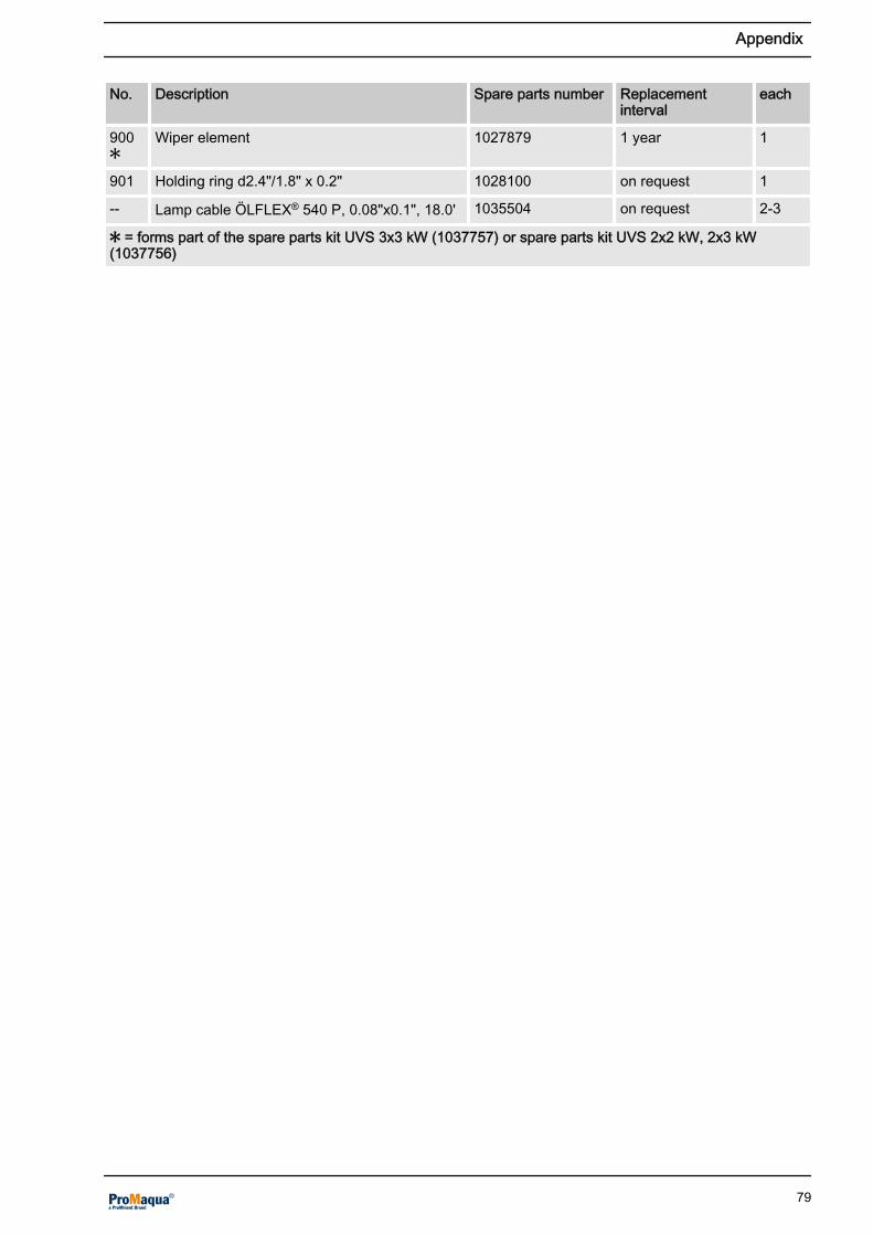
No. Description Spare parts number Replacementinterval
each
900✱
Wiper element 1027879 1 year 1
901 Holding ring d2.4"/1.8" x 0.2" 1028100 on request 1
-- Lamp cable ÖLFLEX® 540 P, 0.08"x0.1", 18.0' 1035504 on request 2-3
✱ = forms part of the spare parts kit UVS 3x3 kW (1037757) or spare parts kit UVS 2x2 kW, 2x3 kW(1037756)
Appendix
79

10.4 Dulcodes S Terminal Wiring Diagram
Power supply at protective low voltagePossible consequence: Fatal or very serious injuries. If connectingthe protective low voltage (SELV) to one of the X4 terminals, theX4 terminals must not be connected to the power supply!
43PE21
1X-
5
3X-
PE 6
43
PE
PE21
3X-
11
7
10
PE
69PE
58PE
PE21
4X-
4BKWHBN 1
2
P06/2.3P05/2.3P04/2.3
P03/3.4P02/3.4
P01/3.4
EP
1 X-
N
1X-
1L
EP N
1 L
EP
2M 4
-
N1LM~ 1FAN
Lüfter (optional)
Relay outputs
Relaisausgänge
Contact inputs
Kontakteingänge(internal use only)(nur intern)
Current
loop outputN
orm-
signal-ausgang
AUSGANG 230VOUTPUT 230V
BETRIEB
OPERATIONRELAIS
RELAY
ALARMRELAISALARM RELAY
PAUSEPAUSE
TEMPERATURFÜHLERTEMPERATURE PROBE
UVC-SENSOR0/4-20mANORMAUSGANGOUTPUTLOOPCURRENT
UVC-SENSOREINGANGINPUT
2 A3
XP:LXP:NXP:PE
XR1:1XR1:2XR1:3
XR2:1XR2:2
XR3:1XR3:2
XR4.1XR4:2
XR5:1XR5:2
XR6:1XR6:2
XR7:3
XR7:1
XR7:2
X2:1X2:2
X2:3X2:4
X2:5X2:6
X2:7X2:8X2:9
X2:10X2:11X2:12
X2:14X2:15
X2:16X2:17
X2:13
S-3
E+ 1
E+3
E-1
EN -
N+
AB
SY
Z-2
E+2 E
INPU
TD
N GV5
+
GY
PKPK
GY
WH
WH
UV-C
-Sensor
WARNUNG
WARNINGRELAIS
RELAY
terminal connections atDulcodes S withoutfunctionKlemmen bei Dulcodes Sohne Funktion
terminal connections atDulcodes S withoutfunctionKlemmen bei Dulcodes Sohne Funktion
terminal connections atDulcodes S withoutfunctionKlemmen bei Dulcodes Sohne Funktion
Wiper forwardWischer vorwärts
Wiper backwardWischer rückwärts
Fig. 41: Dulcodes S Terminal Wiring Diagram
L WARNING
Appendix
80

10.5 Dulcodes UV system unit operating log
Date Turn-onsUV lamp
OperatinghoursUV lamp
Signal dis‐playSensor[%] // [w/ft.2]
UV-trans‐mission[%/1 cm]
Flow[cubicft./h]
Maintenance workMaintenance work
Signature
Appendix
81

11 EC Declaration of Conformity
Fig. 42: EC Declaration of Conformity / Dulcodes without wiper or with manual wiper
EC Declaration of Conformity
82

Fig. 43: EC Declaration of Conformity / Dulcodes with automatic wiper
EC Declaration of Conformity
83

12 Index
BBACK key ............................................................ 14CCHANGE key ...................................................... 14Chloramine............................................................. 5Control cabinet..................................................... 68Cooling mode....................................................... 12DData sheet.............................................................. 5Disinfection support................................................ 5DOWN key .......................................................... 14EEmergency........................................................... 10ENTER key.......................................................... 14FFlashing arrows.................................................... 13Flashing fault alert................................................ 13Formation of coating............................................ 16Fuses................................................................... 68GGeneral non-discriminatory approach.................... 2HHousing................................................................ 14IInputs................................................................... 68LLCD display.................................................... 13, 14Load..................................................................... 68MMaximum temperature ........................................ 12NNon-discriminatory approach................................. 2Normal display..................................................... 14
Normal mode........................................................ 11OOperating error....................................................... 6Operating mode................................................... 14Operating parameters............................................ 9Operating temperature......................................... 11Outputs................................................................. 68Overheating............................................................ 9PPhotochemical........................................................ 5Programing mode................................................. 14SSafety notes........................................................... 7Standard signal output......................................... 68START/STOP key ............................................... 14TTime frame........................................................... 16UUltraviolet radiation................................................ 9UP key ................................................................. 14Use......................................................................... 6Users' qualifications............................................... 8UV lamp switch-off............................................... 12UV output............................................................. 11UV transmission..................................................... 9WWarm-up time ...................................................... 11Water temperature............................................... 12
Index
84

85

86

87

985574, 1, en_US
© 2013
ProMinent Dosiertechnik Heidelberg GmbHIm Schuhmachergewann 5 - 1169123 HeidelbergTelephone: +49 6221 842-0Fax: +49 6221 842-419email: [email protected]: www.prominent.com