Embed Size (px)
Citation preview

Assemble Instruction of Geeetech Acrylic Prusa I3
pro B
Version 04-11-2016

1
Shenzhen GETECH CO.,LTD
GEEETECH
Safety Instructions
Building the printer will require a certain amount of physical dexterity, common sense
and a thorough understanding of what you are doing. We have provided this detailed
instruction to help you assemble it easily.
However ultimately we cannot be responsible for your health and safety whilst
building or operating the printer, with that in mind be sure you are confident with
what you are doing prior to commencing with building or buying. Read the entire
manual to enable you to make an informed decision.
Building and operating involves electricity, so all necessary precautions should be
taken and adhered to, the printer runs on 12V supplied by a certified power supply, so
you shouldn’t ever have to get involved with anything over 12V but bear in mind
there can still be high currents involved and even at 12V they shouldn’t be taken
lightly.
High temperatures are involved with 3D Printing, the Extrusion nozzle of the hot end
can run about 230°C, the heated bed runs 110°C and the molten plastic extruded will
initially be at around 200°C, so special care and attention should be made when
handling these parts of the printer during operation.
We wouldn’t recommend leaving your printer running unattended, or at least until you
are confident to do so. We cannot be held responsible for any loss, damage, threat,
hurt or other negligent result from either building or using the printer.

2
Shenzhen GETECH CO.,LTD
GEEETECH
Preparation
1. Unpack the kit and check if all parts are in the box and check the condition of each
part, there might be some damage during shipping. To help you with this, there is
BOM in the box and each bag was labeled with part number.
2. Contact our customer service immediately by email or through the website if you
find any missing or damaged parts. And on the bottom of the BOM, there is a
signature of reviewer, please take a picture of it and attach the picture in your mail.
3. Read through each chapter of these instructions to gain an over-all idea of what is
involved and how long it might take, before starting on the work described.
4. Before you start, you can put all the part in order to save your time especially those
screws and nuts. Do not mix them up.
5. Ensure you have the necessary skills to carry out the work, or enlist the help of
someone who does.
6. Work on a big firm table or bench in a clean dry well-lit area.
7. This kit contains tiny parts; please keep them away from kids under 3.
8. Ask for help if you run into any problems - our contact details are on the website
and we will always do our best to resolve any problems encountered.
3
Shenzhen GETECH CO.,LTD
GEEETECH
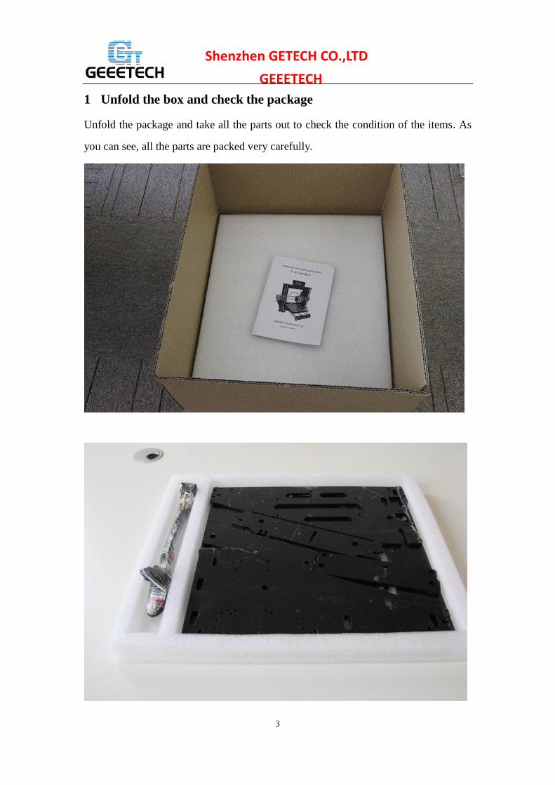
1 Unfold the box and check the package
Unfold the package and take all the parts out to check the condition of the items. As
you can see, all the parts are packed very carefully.

4
Shenzhen GETECH CO.,LTD
GEEETECH All the acrylic plate has been etched with part ID and the plate is covered with
a sheet of Kraft paper, you need to tear them off.
5
Shenzhen GETECH CO.,LTD
GEEETECH Tips:
1. Before assembly, you are advised to put all the parts, especially the screws and nuts
in order, which will save you a lot of time looking for the required parts.
2. The part ID is corresponding to the number labeled on the bag of every part. Some
parts may not have label, you can refer to the pictures on the package list.
2 Assemble the rods of a Y axis
Watch the video
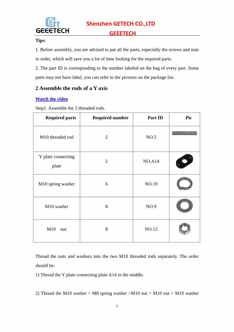
Step1. Assemble the 2 threaded rods.
Pic Part ID Required number Required parts
NO.5 2 M10 threaded rod
NO.A14 2 Y plate connecting
plate
NO.19 6 M10 spring washer
NO.9 8 M10 washer
NO.13 8 M10 nut
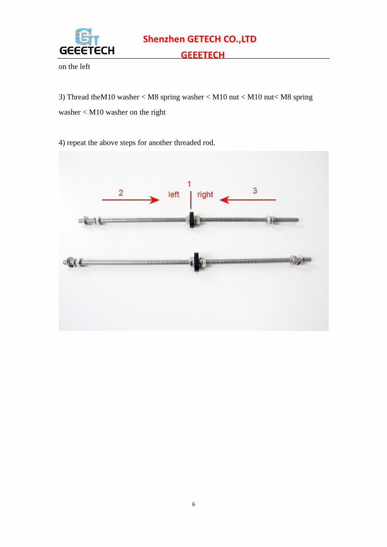
Thread the nuts and washers into the two M10 threaded rods separately. The order
should be:
1) Thread the Y plate connecting plate A14 in the middle.
2) Thread the M10 washer > M8 spring washer >M10 nut > M10 nut > M10 washer
6
Shenzhen GETECH CO.,LTD
GEEETECH on the left
3) Thread theM10 washer < M8 spring washer < M10 nut < M10 nut< M8 spring
washer < M10 washer on the right
4) repeat the above steps for another threaded rod.

7
Shenzhen GETECH CO.,LTD
GEEETECH
Step2. Assemble the 2 smooth rods
Pic Part ID Required number Required parts
NO.3 3 M8 smooth rod
NO.36 4 LM8UU Linear
bearings
Take out the 410mm smooth rod
Slide 2 Linear bearings on each smooth rod. Before you slide the bearings please
make sure they are clean.

8
Shenzhen GETECH CO.,LTD
GEEETECH
3 Attach the front and rear support plates
Watch the video
For some of the kit, the locking rings are the silver color, which will not affect the
assembly here, but in some steps, for the X axis, there is difference, please pay
attention to the note.
9
Shenzhen GETECH CO.,LTD
GEEETECH
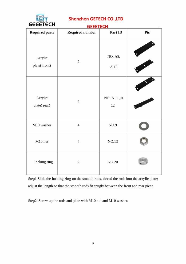
Step1.Slide the locking ring on the smooth rods, thread the rods into the acrylic plate;
adjust the length so that the smooth rods fit snugly between the front and rear piece.
Step2. Screw up the rods and plate with M10 nut and M10 washer.
Pic Part ID Required number Required parts
NO. A9,
A 10
2
Acrylic
plate( front)
NO. A 11, A
12
2
Acrylic
plate( rear)
NO.9 4 M10 washer
NO.13 4 M10 nut
NO.20 2 locking ring

10
Shenzhen GETECH CO.,LTD
GEEETECH
* Tips: Try to keep the rods parallel and the four acrylic pieces parallel. The Y-axis
must be a rectangle, that is the rods on both side should be parallel, so is the front and
back plate. Otherwise it will cause obstruction for the belt later. You can use a Digital
Caliper to measure.
*Note: As we re-designed the rear plate, there are two more holes on A12, in this
case, you need to use the screw locking ring to fix the smooth rod.
4 Assemble the Y idler
Watch the video
Pic Part ID Required number Required parts
NO.46 2 Ball bearing

11
Shenzhen GETECH CO.,LTD
GEEETECH
NO.41 1 bearing holder
No.45 1 Driven wheel
NO.28 1 M3 x 20 screw
NO.16 1 M3 wing nut
NO.33 1 M4 x25 screw
NO.15 1 M4 lock nut
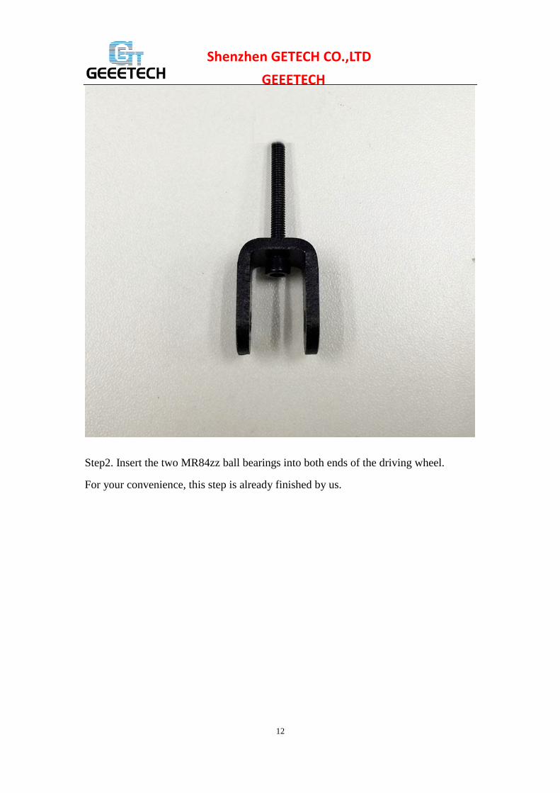
Step1. Thread the M3 x 20mm screw through the bearing holder.
12
Shenzhen GETECH CO.,LTD
GEEETECH
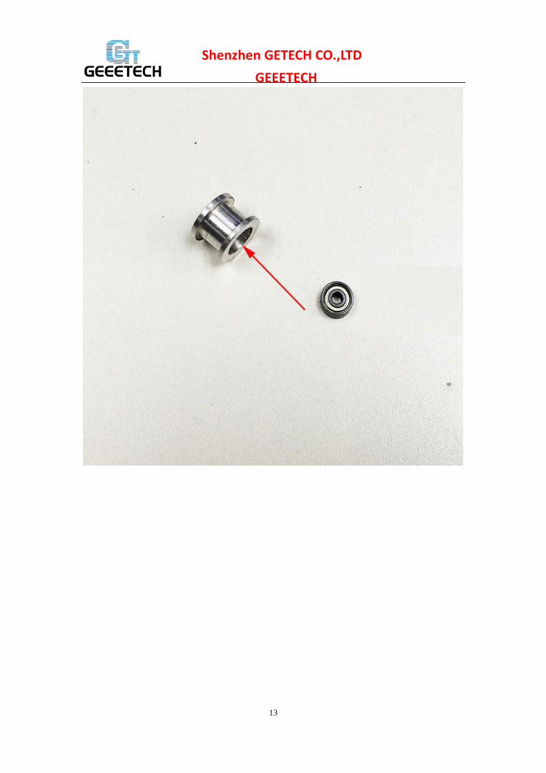
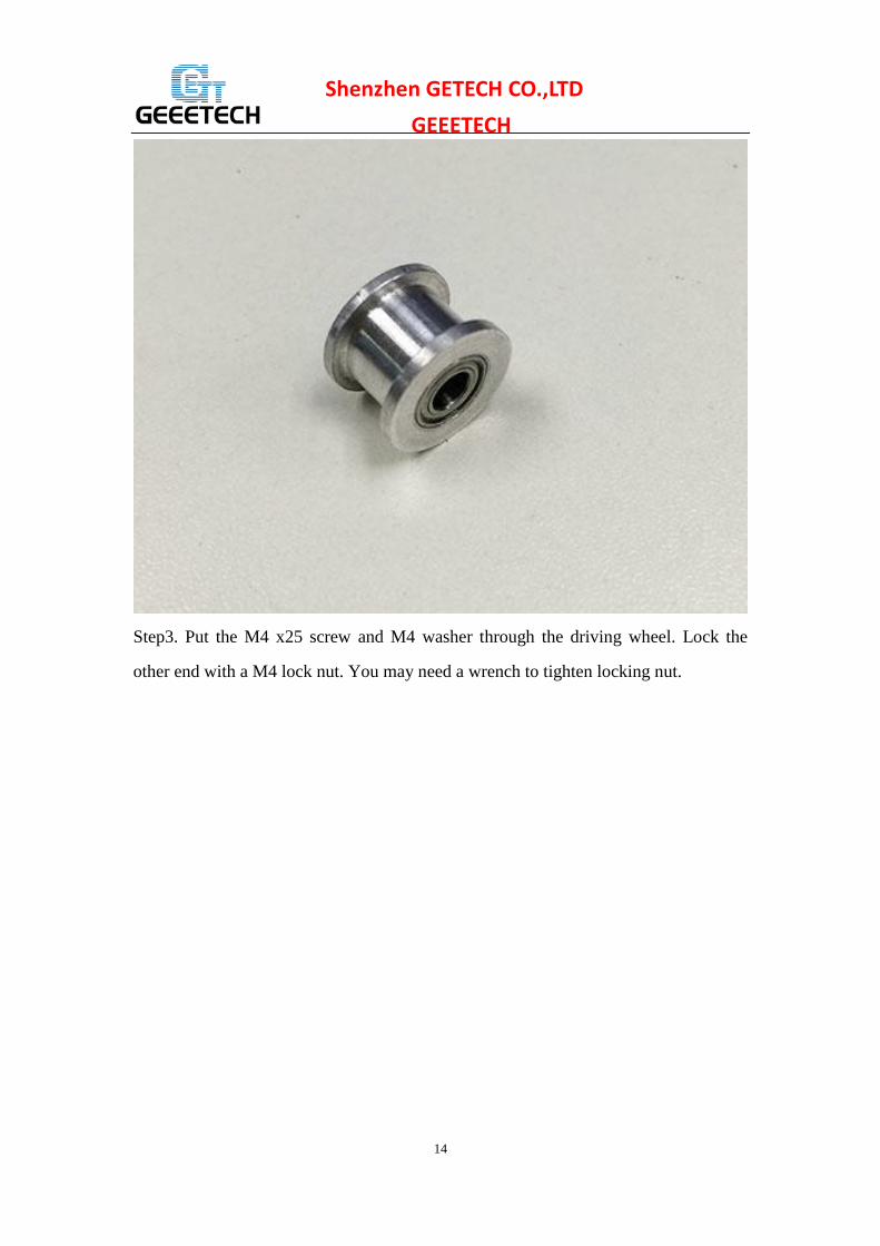
Step2. Insert the two MR84zz ball bearings into both ends of the driving wheel.
For your convenience, this step is already finished by us.
13
Shenzhen GETECH CO.,LTD
GEEETECH
14
Shenzhen GETECH CO.,LTD
GEEETECH
Step3. Put the M4 x25 screw and M4 washer through the driving wheel. Lock the
other end with a M4 lock nut. You may need a wrench to tighten locking nut.

15
Shenzhen GETECH CO.,LTD
GEEETECH
16
Shenzhen GETECH CO.,LTD
GEEETECH
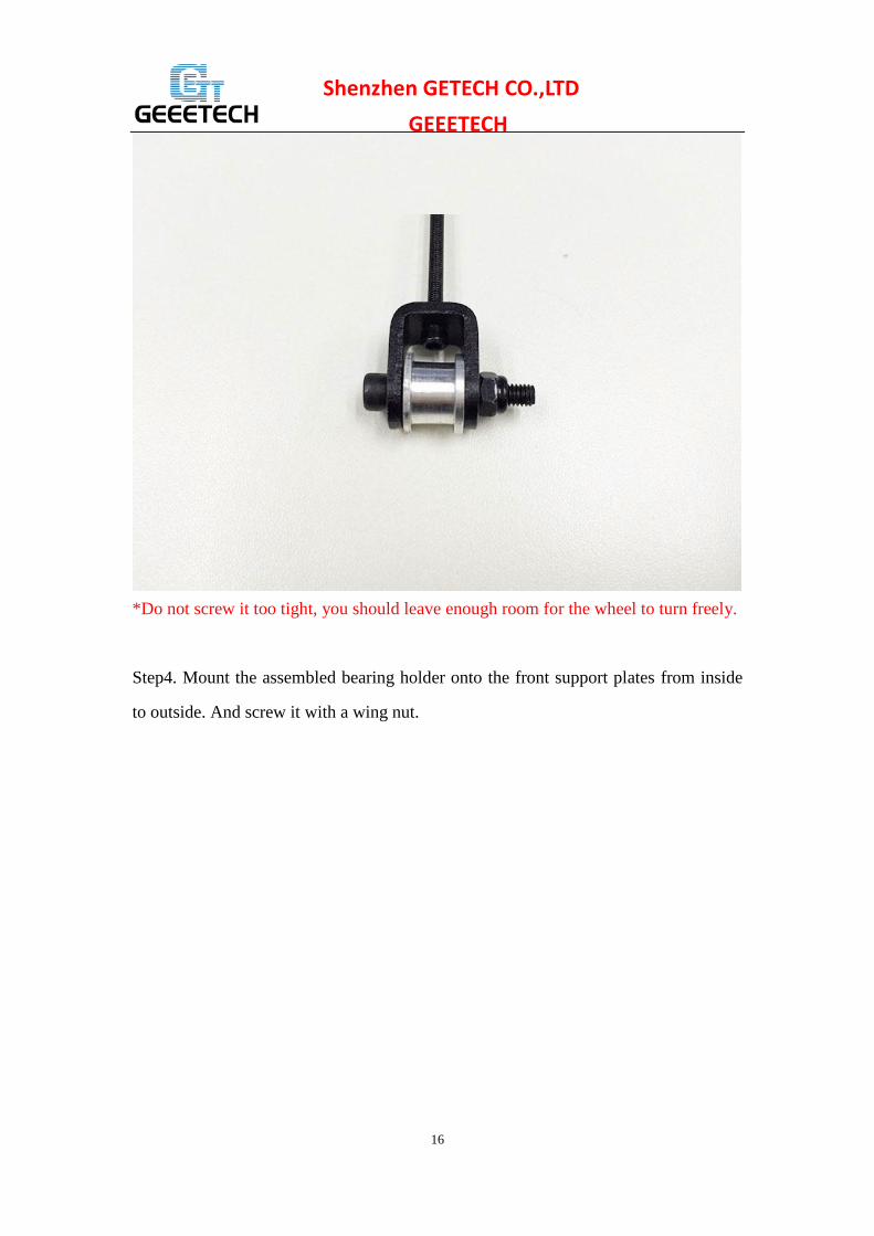
*Do not screw it too tight, you should leave enough room for the wheel to turn freely.
Step4. Mount the assembled bearing holder onto the front support plates from inside
to outside. And screw it with a wing nut.

17
Shenzhen GETECH CO.,LTD
GEEETECH
5 Mount the Y motor
Watch the video
Pic Part ID Required number Required parts
NO. A13 1 Y motor fix plate

18
Shenzhen GETECH CO.,LTD
GEEETECH
NO.62 1 Stepper motor
NO.44 1 Pulley
NO.26 3 M3 x 12 screw
NO.28 2 M3 x 20 screw
NO.17 2 M3 square nut
Note: In some picture, the pulley is a bit different but it won’t affect your assembly.
Step1. Mount the pulley on the motor shaft, one of the screws should be screwed on
the flat side of the shaft. Screw it as tight as possible.
19
Shenzhen GETECH CO.,LTD
GEEETECH
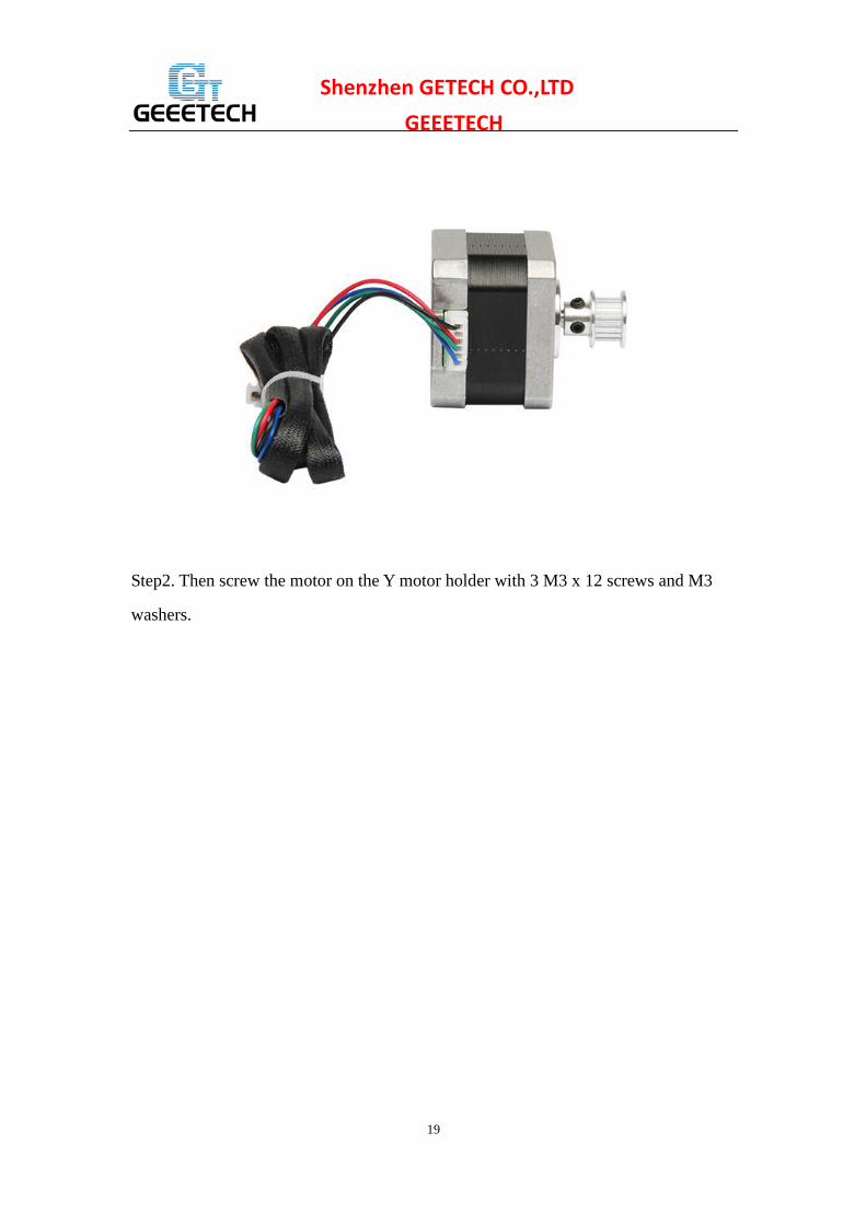
Step2. Then screw the motor on the Y motor holder with 3 M3 x 12 screws and M3
washers.

20
Shenzhen GETECH CO.,LTD
GEEETECH
Step3. Push the Y Motor holder tab into the square hole in Rear -Outside Plate and
Rear - Inside Plate. You may need to use a little force, but be careful not to break or
crack any of the Acrylic pieces.
Secure the Y Motor holder with 2 M3x20mm screws, M3 Washers and M3 Square
Nuts.

21
Shenzhen GETECH CO.,LTD
GEEETECH
6 Build the printing platform
Watch the video
Pic Part ID Required number Required parts
NO.A15 1 Y platform support
NO.A16 4 Y bearing block

22
Shenzhen GETECH CO.,LTD
GEEETECH
NO.42 1 Belt mount
NO.66
4
Nylon tie
NO.25 2 M3 x 10 screw
NO.28 8 M3 x 20 screw
NO.11 8 M3 nut
Step1. Mount the belt mount on the bottom side of the platform with 2 M3 x 10
screws.

23
Shenzhen GETECH CO.,LTD
GEEETECH
Step2. Mount the 4 bearing blocks on the platform with M3 x 20 screws on the same
side with the belt-mount. Screw with M3 nuts.
Step3. Get the build platform plate zip-tied to the 4 linear bearings of Y- Axis.
*The belt-mount and the fenders are under the platform.

24
Shenzhen GETECH CO.,LTD
GEEETECH

25
Shenzhen GETECH CO.,LTD
GEEETECH
7 Mount the Y –axis belt
Watch the video
Pic Part ID Required number Required parts
NO.39 1 Timing belt
NO.25 2 M3 x 10 screw
NO.7 2 M3 washer
Step1. Drill a hole on one end of the belt(the hole can be as the diameter of the M3
screw, leave enough margin )

26
Shenzhen GETECH CO.,LTD
GEEETECH Step2. Fix the belt on one side of the belt -mount with a M3 x 10 screw and washer.
Step3. Thread the belt around the driven wheel on the motor and the Y idler.
Step4. Drill a hole on the other end of the belt and fix it on the belt -mount with a M3
x 10 screw and M3 washer.
*Tips:
1. before you drill your second hole, make sure to pull belt tightly to make sure to find
proper placement of hole for a tight belt, if it is too loose, it will hinder the move of t
he print platform.

27
Shenzhen GETECH CO.,LTD
GEEETECH
8 mount the End stop of Y-axis
Watch the video

28
Shenzhen GETECH CO.,LTD
GEEETECH Pic Part ID Required number Required parts
NO.56
1 End stop
NO.22 2 M2.5 x 16 screw
NO.10 2 M2.5 Hex nut
Mount the end stop on the rear support plate of Y axis with M2.5 X 16 screw and
M2.5 Hex nut.
29
Shenzhen GETECH CO.,LTD
GEEETECH
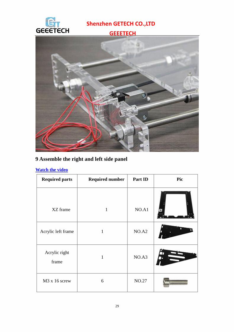
9 Assemble the right and left side panel
Watch the video
Pic Part ID Required number Required parts
NO.A1
1
XZ frame
NO.A2 1 Acrylic left frame
NO.A3 1 Acrylic right
frame
NO.27 6 M3 x 16 screw

30
Shenzhen GETECH CO.,LTD
GEEETECH
NO.17 6 M3 square nut
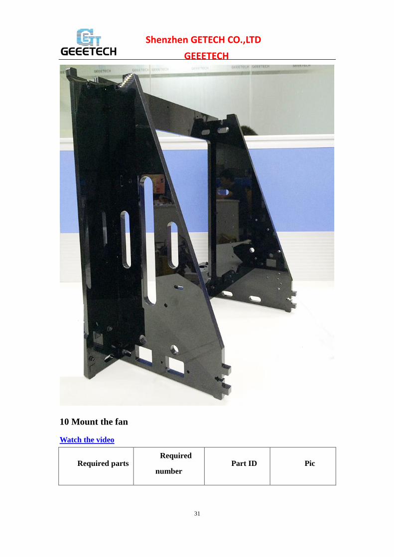
Step1. Screw up the X-Z frame and the side panel with M3 x 16 screws and M3
square nuts.
If the holes not fit, please use the file to trim it.
31
Shenzhen GETECH CO.,LTD
GEEETECH
10 Mount the fan
Watch the video
Pic Part ID Required
number Required parts

32
Shenzhen GETECH CO.,LTD
GEEETECH
NO.53 1 Fan
NO.29 4 M3 x 30 screw
NO.14 4 M3 locknut
Fix the fan on the left side of the frame with 4 M3 x 30 screw and lock nut. Mind the
direction of the wires. (Please pay attention to the direction of the fan)
If you don’t want to use the lock nut you can use hex nut.
33
Shenzhen GETECH CO.,LTD
GEEETECH
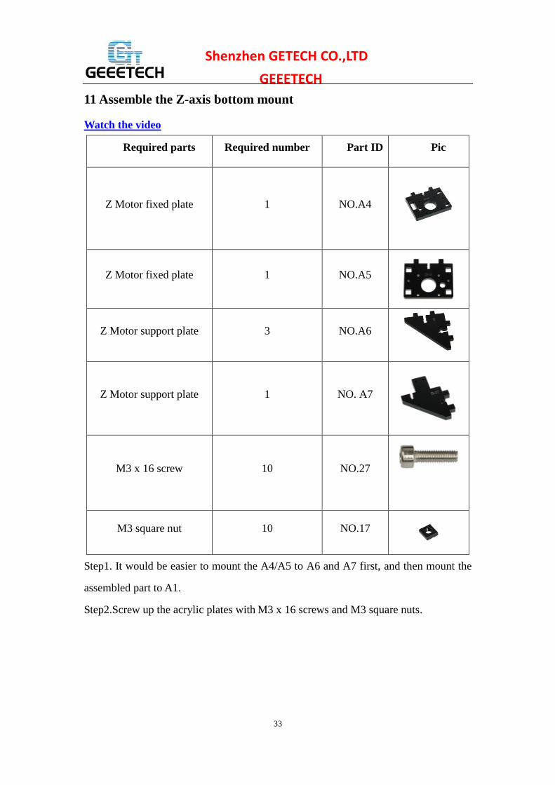
11 Assemble the Z-axis bottom mount
Watch the video
Pic Part ID Required number Required parts
NO.A4 1 Z Motor fixed plate
NO.A5 1 Z Motor fixed plate
NO.A6 3 Z Motor support plate
NO. A7 1 Z Motor support plate
NO.27 10 M3 x 16 screw
NO.17 10 M3 square nut
Step1. It would be easier to mount the A4/A5 to A6 and A7 first, and then mount the
assembled part to A1.
Step2.Screw up the acrylic plates with M3 x 16 screws and M3 square nuts.
34
Shenzhen GETECH CO.,LTD
GEEETECH
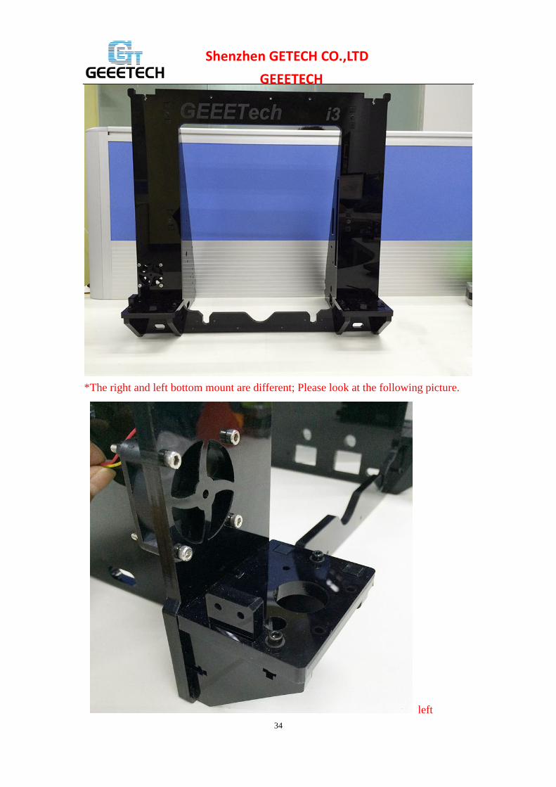
*The right and left bottom mount are different; Please look at the following picture.
left

35
Shenzhen GETECH CO.,LTD
GEEETECH
right
12 Assemble Y - Z axis
Watch the video
Pic Part ID Required number Required parts
NO.27 2 M3 x 16 screw
NO.28 4 M3 x 20 screw
NO.11 4 M3 nut
NO.17 2 M3 square nut
Step1. Put the Y axis between the main frame.

36
Shenzhen GETECH CO.,LTD
GEEETECH
Step2. Screw up the main frame to the acrylic fender with 4 M3 x 20 screws. And
screw up the M10 nuts.
37
Shenzhen GETECH CO.,LTD
GEEETECH
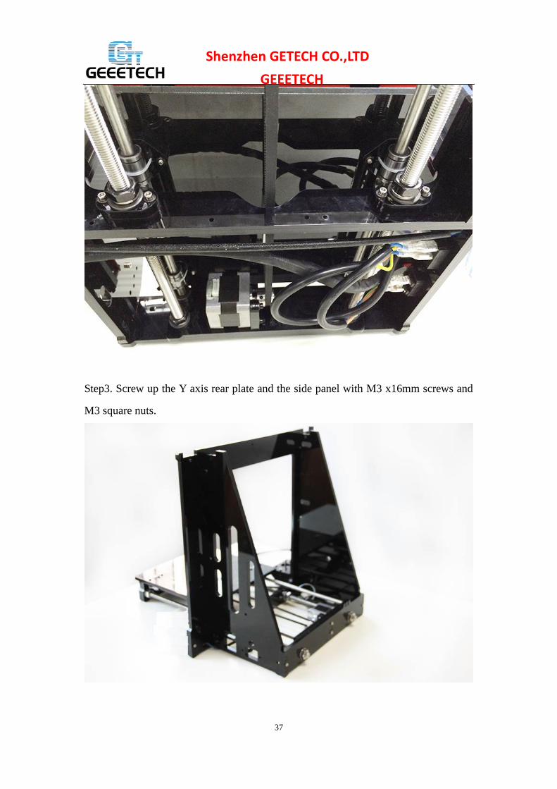
Step3. Screw up the Y axis rear plate and the side panel with M3 x16mm screws and
M3 square nuts.

38
Shenzhen GETECH CO.,LTD
GEEETECH 13 Mount Z-axis End stop
Watch the video
Pic Part ID Required number Required parts
NO.56 1 End stop
NO.22 2 M 2.5 X 16 screw
NO.10 2 M 2.5 nut
Mount the endstop on the outside of A7 with M2.5 x 16mm screw and M2.5 hex nut.

39
Shenzhen GETECH CO.,LTD
GEEETECH
14 Assemble the 2 Z motors
Watch the video
Pic Part ID Required number Required parts
NO.62 2 Stepper Motor
NO.26 8 M3 x 12screw
Step1.Thread the wires of the motors through the holes
Step2. Screw up the motors with 4 M3 x 12 screws.
Do the same with the other Z motor.

40
Shenzhen GETECH CO.,LTD
GEEETECH
15 Assemble the coupling.
Watch the video
Pic Part ID Required number Required parts
NO.43 2 Couplings
Step1. Fix the two couplings on both of the motor shaft.
Please note:
1. The opening of both end, one is 5mm, another is 8mm, connect the 5mm hole to the
motor shaft.
2. Screw the small bolt of the 5mm part on the upper part of the flat side of the
motor shaft tightly.

41
Shenzhen GETECH CO.,LTD
GEEETECH

42
Shenzhen GETECH CO.,LTD
GEEETECH
16 Attach he heated bed.
Watch the video
Pic Part ID Required number Required parts
NO.59
1
Heat bed set
NO.30 4 M3 x35 screw
NO.7 12 M3 washer
NO.35
4
Spring
43
Shenzhen GETECH CO.,LTD
GEEETECH
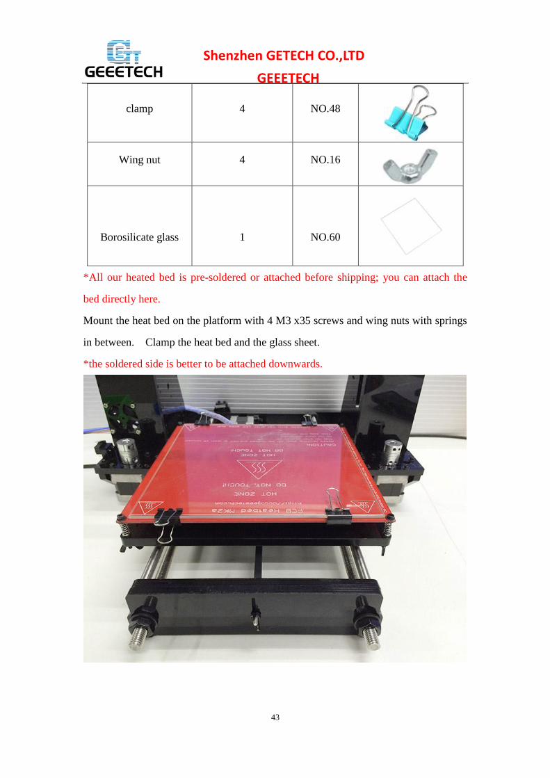
NO.48 4 clamp
NO.16 4 Wing nut
NO.60
1
Borosilicate glass
*All our heated bed is pre-soldered or attached before shipping; you can attach the
bed directly here.
Mount the heat bed on the platform with 4 M3 x35 screws and wing nuts with springs
in between. Clamp the heat bed and the glass sheet.
*the soldered side is better to be attached downwards.

44
Shenzhen GETECH CO.,LTD
GEEETECH
17 Mount the X-axis motor end
Watch the video
Part name Part ID Required number pic
Z-axis nut
No.18 1
X-axis motor end
No.M1
1
Linear Bearing
LMH8LUU
No. 38
1

45
Shenzhen GETECH CO.,LTD
GEEETECH
M3 x 30 screw No.29 1
M3 x 6mm screw No. 23 8
M3 washer No. 7 2 \
Spring No. 35 1
Step1. Mount the Z nut on the X-axis left end from bottom to up, fix with M3 x 6mm
screws.
Step2. Mount the linear bearing on X-axis motor end from bottom to up. Fix it up
with M3 x 6mm screws.
46
Shenzhen GETECH CO.,LTD
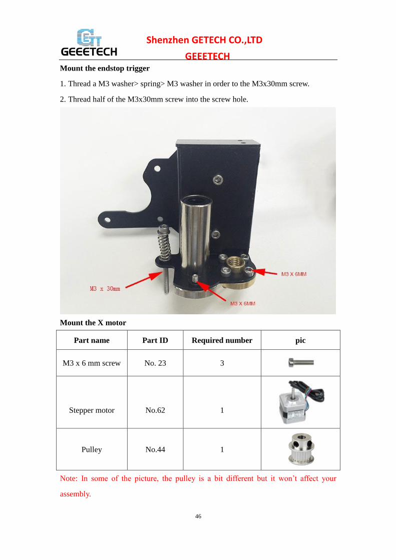
GEEETECH Mount the endstop trigger
1. Thread a M3 washer> spring> M3 washer in order to the M3x30mm screw.
2. Thread half of the M3x30mm screw into the screw hole.
Mount the X motor
Part name Part ID Required number pic
M3 x 6 mm screw No. 23 3
Stepper motor
No.62
1
Pulley No.44 1
Note: In some of the picture, the pulley is a bit different but it won’t affect your
assembly.

47
Shenzhen GETECH CO.,LTD
GEEETECH
Step1. Mount the pulley on the motor shaft. Screw it on the flat side.
Step2.Mount the stepper motor on the motor end with 3 M3 x 6 mm screw.

48
Shenzhen GETECH CO.,LTD
GEEETECH

49
Shenzhen GETECH CO.,LTD
GEEETECH Mount the endstop
Part name Part ID Required number pic
M2.5 x 8 mm
screw No. 21 2
End stop
No.56
1
Mount the endstop on the top of X-axis motor end with M2.5 x 8mm screws

50
Shenzhen GETECH CO.,LTD
GEEETECH
18 Assemble X axis idler end
Watch the video
Part name Part ID Required number pic
Z-axis nut
No.18 1
X-axis idle end
No.M2
1
Linear Bearing
LMH8LUU
No. 38
1

51
Shenzhen GETECH CO.,LTD
GEEETECH M3 x 6mm screw No. 23 8
Step1.Mount the Z axis nut on the bottom of X-axis right end with 4 M3 x 6mm
screws.
Step2. Mount the linear bearing on X-axis motor end from bottom to up. Fix it up
with M3 x 6mm screws.

52
Shenzhen GETECH CO.,LTD
GEEETECH

53
Shenzhen GETECH CO.,LTD
GEEETECH
19 Assemble the extruder carriage
Watch the video
Part name Part ID Required number pic
X
Carriage
No.M3
1
Bearing Bracket No.M4 4
Extruder holder
No.M5
1
Linear Bearing
LM8LUU No.37 2
Belt bracket
No.51
1
M3x6mm screw No. 23 8
M3x12mm screw No. 26 2
M4x6mm screw No. 32 2
M3 nut No.11 2
Step1. Fix the 4 Bearing Brackets on the back of the X Carriage loosely with
M3x6mm screws.

54
Shenzhen GETECH CO.,LTD
GEEETECH

55
Shenzhen GETECH CO.,LTD
GEEETECH
Insert the linear bearing into the slot and screw the bracket tightly.

56
Shenzhen GETECH CO.,LTD
GEEETECH

57
Shenzhen GETECH CO.,LTD
GEEETECH
Please notice the front and back of the plate.
Step2. Fix the belt bracket on the back of the carriage with 2 M3x 12mm screws and
M3 hex nuts.

58
Shenzhen GETECH CO.,LTD
GEEETECH

59
Shenzhen GETECH CO.,LTD
GEEETECH
Step3. Fix the extruder holder on the front side of the X carriage using M4x6mm
screws.

60
Shenzhen GETECH CO.,LTD
GEEETECH

61
Shenzhen GETECH CO.,LTD
GEEETECH

62
Shenzhen GETECH CO.,LTD
GEEETECH
20 Assemble the X&Z axis
Watch the video
Part name Part ID Required number pic
L300mm threaded
rod No.4 2
L322mm smooth
rod No.1 2

63
Shenzhen GETECH CO.,LTD
GEEETECH L390mm smooth
rod No.2 2
locking ring
No.20 4
Step1. Thread the L300 threaded rod to the nut of both end of X axis.
Keep both end of X axis at the same place of the rod, you are advised to measure the
distance of the both side so that they are at the same level when you put them up.
Step2. Plug the threaded rod on the X motor end to the left coupling on the left bottom
of the Z axis. Then thread the 320mm smooth rod into the linear bearing.
64
Shenzhen GETECH CO.,LTD
GEEETECH
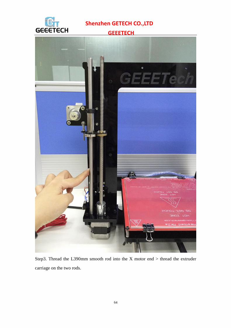
Step3. Thread the L390mm smooth rod into the X motor end > thread the extruder
carriage on the two rods.
65
Shenzhen GETECH CO.,LTD
GEEETECH
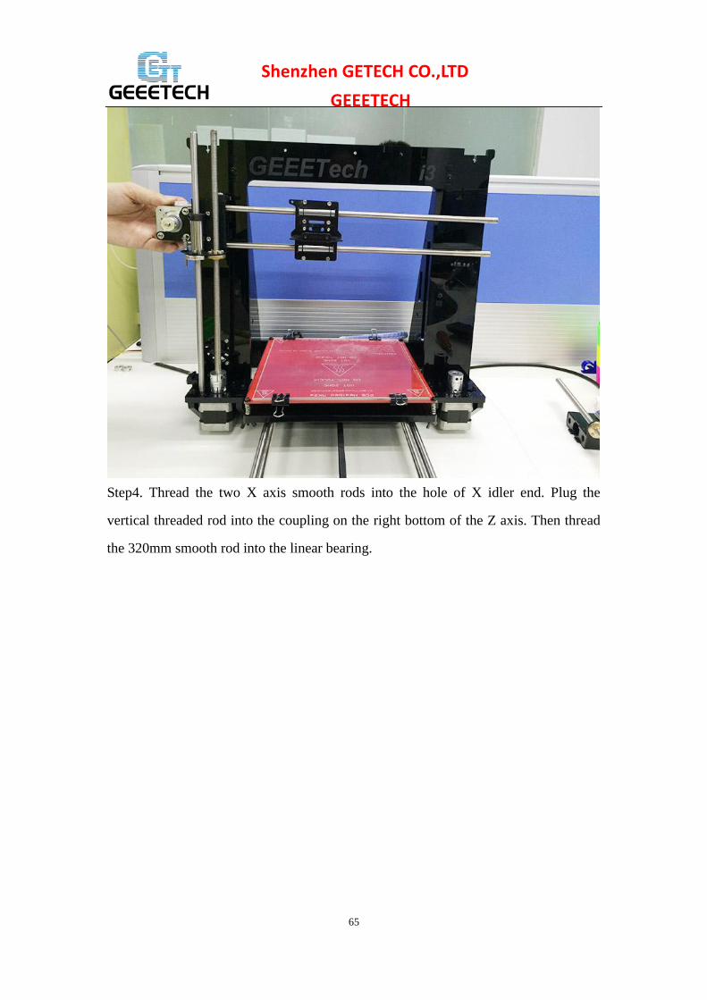
Step4. Thread the two X axis smooth rods into the hole of X idler end. Plug the
vertical threaded rod into the coupling on the right bottom of the Z axis. Then thread
the 320mm smooth rod into the linear bearing.

66
Shenzhen GETECH CO.,LTD
GEEETECH
Note: the smooth rods and the threaded rod of Z axis are vertical and the X axis is
horizontal, which is very important, or it will hinder the move of the Z axis.
Step5. Fix the locking rings on the end of the rod if you got the silver rings.

67
Shenzhen GETECH CO.,LTD
GEEETECH
NOTE: If you got the black lock ring (No.20), you need to fix all the 4 locking rings
on the right end, as shown on the following picture.

68
Shenzhen GETECH CO.,LTD
GEEETECH
21 Assemble the Z axis top mount
Watch the video
Part name Part ID Required number pic
Z top mount
No.A8
2
M3 x 16mm screw No.27 4
M3 Square nut No.17 4
locking ring
No.20 2
69
Shenzhen GETECH CO.,LTD
GEEETECH
M3 washer No. 7 6 \
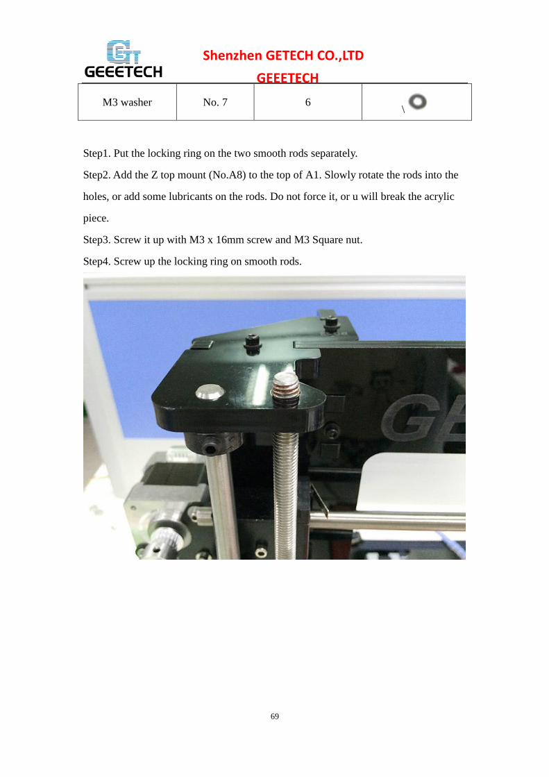
Step1. Put the locking ring on the two smooth rods separately.
Step2. Add the Z top mount (No.A8) to the top of A1. Slowly rotate the rods into the
holes, or add some lubricants on the rods. Do not force it, or u will break the acrylic
piece.
Step3. Screw it up with M3 x 16mm screw and M3 Square nut.
Step4. Screw up the locking ring on smooth rods.

70
Shenzhen GETECH CO.,LTD
GEEETECH
22 Mount the extruder
Watch the video
Pic Part ID Required Number Required parts
NO.63
1
MK8 extruder
NO.32 2 M4 x 6mm screw
NO.8 2 M4 washer
Step1. Mount the assembled extruder on the extruder holder. Use 2 M4 x 6 mm
screws and M4 washers to fix.

71
Shenzhen GETECH CO.,LTD
GEEETECH

72
Shenzhen GETECH CO.,LTD
GEEETECH
23 X belt driven wheel
Watch the video
This video is just for referring, you need to use M3 x40mm screw.
Part name Part ID Required number pic
Driven wheel
holder
No.41
1
Driven wheel No.45 1
MR84zz Ball
Bearing
No.46
2
M3 x40mm screw No.31 1
M4 x 25mm screw No.33 1
M3 washer No.7 1
M4 washer No.8 1
M4 lock nut No.15 1
wing nut No.16 1
Step1. Thread the M3 x 40 screw and M3 washer through the Driven wheel holder .
73
Shenzhen GETECH CO.,LTD
GEEETECH
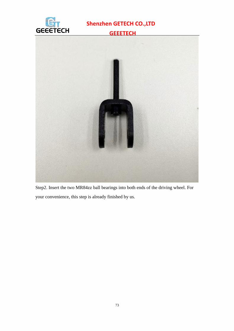
Step2. Insert the two MR84zz ball bearings into both ends of the driving wheel. For
your convenience, this step is already finished by us.

74
Shenzhen GETECH CO.,LTD
GEEETECH

75
Shenzhen GETECH CO.,LTD
GEEETECH Step3. Put the M4 x25 screw and M4 washer through the driving wheel. Lock the
other end with a M4 lock nut. You may need a wrench to tighten locking nut.

76
Shenzhen GETECH CO.,LTD
GEEETECH
*Do not screw it too tight, you should leave enough room for the wheel to turn freely.
24 Add the X axis belt
Watch the video
Part name Part ID Required number pic
Timing belt No.40 1
Step1. Insert one end of the belt in the groove. Pay attention to the tooth mesh of the
belt and the groove.
Step2. Thread another end of the belt through the X motor end around the pulley.
Step3. Thread the belt through the belt driven wheel and put the driving wheel into the
X idler end, lock it with a wing nut.
Step4. Insert another end of the belt into the groove. Cut the spare part. Be sure of the
length of the belt.
Step5. Taut the belt and tighten the wing nut on the idle end.

77
Shenzhen GETECH CO.,LTD
GEEETECH

78
Shenzhen GETECH CO.,LTD
GEEETECH

79
Shenzhen GETECH CO.,LTD
GEEETECH *Note the direction of the driven wheel, the side with bolt head should be towards the
A1, or it will scratch the acrylic plate.
25 Mount the LCD panel frame
Watch the video
Pic Part ID Required number Required parts
NO.65
1 LCD 2004
NO.A18 1
LCD frame
NO.A19
2 LCD frame holder
NO.A17
4 Acrylic spacer
NO.28 6 M3 x 20 screw
NO.11 4 M3 nut
NO.52
1 Knob
Step1. Cover the LCD frame to the LCD panel.
Step2. Use a M3 x 20 screw to connect the spacer> LCD frame holder >the LCD
frame and the LCD 2004 in order, fix with M3 nut.

80
Shenzhen GETECH CO.,LTD
GEEETECH

81
Shenzhen GETECH CO.,LTD
GEEETECH

82
Shenzhen GETECH CO.,LTD
GEEETECH
26. Mount the PSU
Watch the video
Pic Part ID Required number Required parts
NO.61
1 Power supply
NO.25 3 M3 x 10 screw
NO.34 2 M3 x 16 bolt
NO.11 2 M3 nut
NO.57 1 3D Power cable
NO.58 1 Power Cable
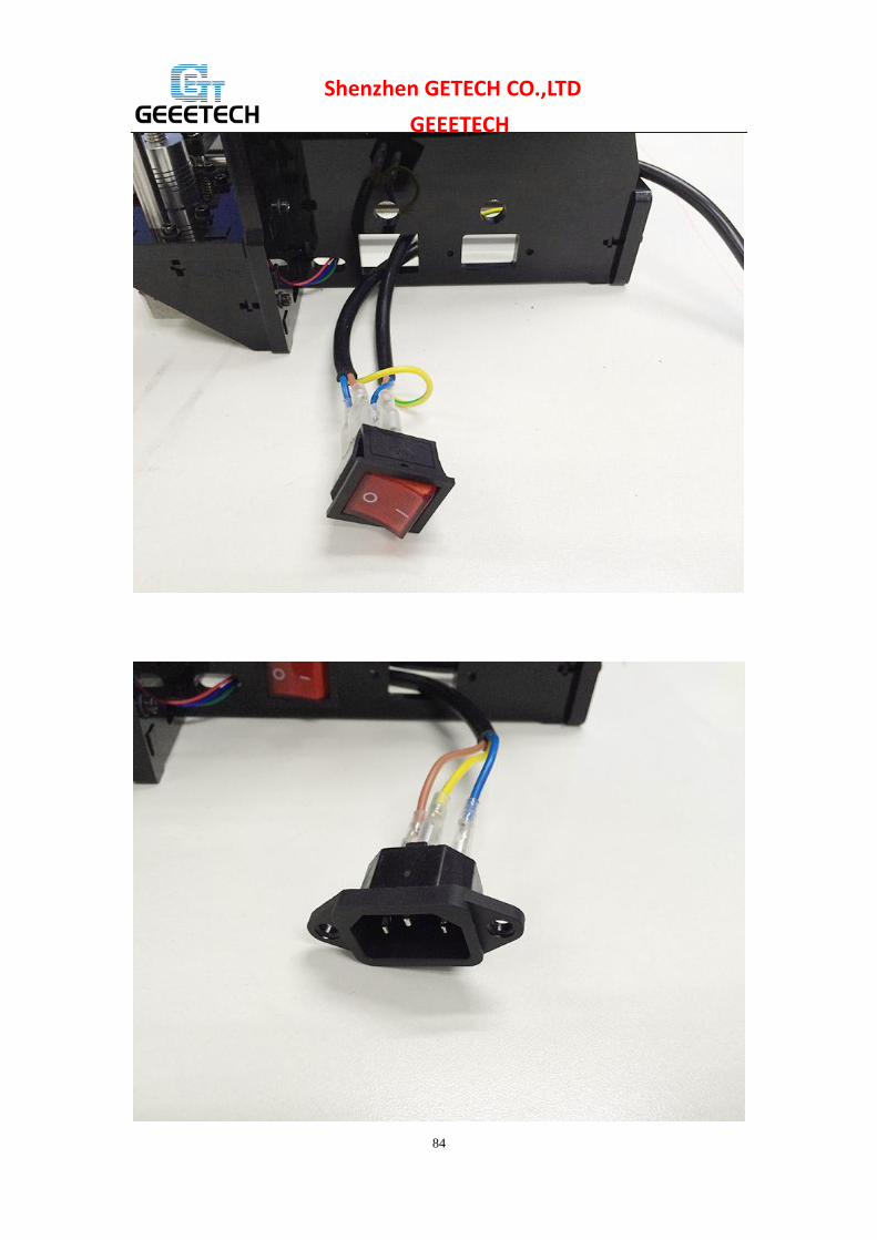
Step1. Take off the wires connected to the socket; before you do, please take a photo
of the wire connection, in case you connect them wrongly later.

83
Shenzhen GETECH CO.,LTD
GEEETECH
84
Shenzhen GETECH CO.,LTD
GEEETECH

85
Shenzhen GETECH CO.,LTD
GEEETECH Step2. Mount the socket on the bottom of the right side panel with 2 M3 x 16 Hex
Counter- sunk-head screws and M3 hex nut.
Step3. Thread the wires out.

86
Shenzhen GETECH CO.,LTD
GEEETECH
Step3. Mount the PSU (Power supply unit) on the right side panel with 3 M3 x 10
screws.

87
Shenzhen GETECH CO.,LTD
GEEETECH
Step5. Now we can connect the wires to the PSU.
1) Mind the color of the wires. The wrong connection of the wire will cause serious
damage to the PSU and even to the control board of the printer.
As you can see, there are 7 wires and 7 screws in total.
Note the correspondence between the color of wires and the connector.
Brown------L
Blue ------N
Yellow------ GND
Red ------ --+ V
Black------COM

88
Shenzhen GETECH CO.,LTD
GEEETECH
2) Pay attention to the switch on the right side of the PSU, there are two options of
voltage: 110 V and 220V, choose according the standard in your country. As shown in
the following picture. Remove the yellow paper; you can use some hard sticks to
reach the switch.

89
Shenzhen GETECH CO.,LTD
GEEETECH
Close the cover of the connector in case any electric shock.
27. Mount the control board
Watch the video
Part name Part ID Required number pic
Control board kit No.64 1
Sticker
No.50
1
Heat sink
No.49
1
Spacer
No.47 4
M3 x 12 mm screw No.26 4

90
Shenzhen GETECH CO.,LTD
GEEETECH Step1. Cut the sticker into small pieces.
Step2. Past the heat sink onto the chip of the A4988 drivers (on the main board) . The
sticker is double sided adhesive.
Step3. Insert the spacer into the holes of the board from back to front, Mount the
board kit on the left side panel with 4 M3 x 12mm screws and M3 washers on the side
panel.
Note the direction of the board; the green connectors are downwards to get enough
heat dissipation from the fan.
28 Wiring
GT2560
Before you start wiring, please take a look at the wiring schematics.

91
Shenzhen GETECH CO.,LTD
GEEETECH
You can see original picture here.
Step1. The subdivision of stepper motor can be setup by jumper cap, plug all the
jumper caps (For A4988)

92
Shenzhen GETECH CO.,LTD
GEEETECH
If you are using DRV8825 instead of A4988, the jumper caps should be changed as
follow:
Note please, as your printer is single extruder, you will not use the extruder 2.
93
Shenzhen GETECH CO.,LTD
GEEETECH
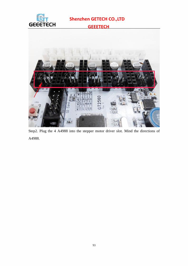
Step2. Plug the 4 A4988 into the stepper motor driver slot. Mind the directions of
A4988.

94
Shenzhen GETECH CO.,LTD
GEEETECH
If you are using DRV8825 instead of A4988, The correct connections are as follow:
For your convenience, the above two steps is finished by us. you can skip them.
95
Shenzhen GETECH CO.,LTD
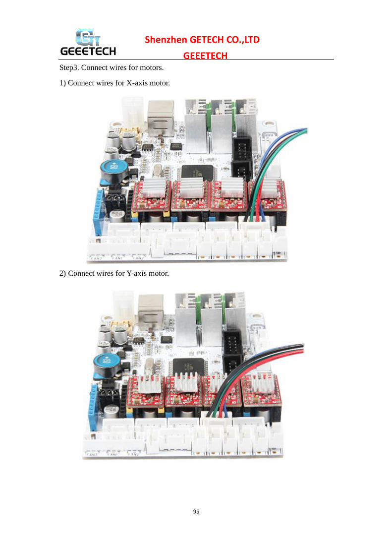
GEEETECH Step3. Connect wires for motors.
1) Connect wires for X-axis motor.
2) Connect wires for Y-axis motor.

96
Shenzhen GETECH CO.,LTD
GEEETECH 3) Connect wires for 2 Z-axis motors.
97
Shenzhen GETECH CO.,LTD
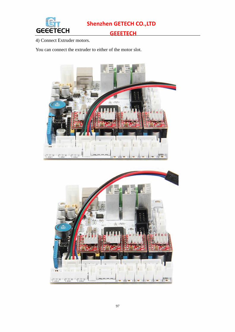
GEEETECH 4) Connect Extruder motors.
You can connect the extruder to either of the motor slot.

98
Shenzhen GETECH CO.,LTD
GEEETECH Step4. Connect heating wires.
Loosed the screws in the green terminal and put the red wires into the slot and screw
it up. * There is no “+” and “-“for heating wires
1) Connect heating wires for heatbed.
2) Connect heating wires for extruder 1.

99
Shenzhen GETECH CO.,LTD
GEEETECH 3) Connect heating wires for extruder 2.
Step4. Connect wires for thermistor.
1) Connect wires for thermistor of heatbed.
2) Connect wires for thermistor of extruder 1.

100
Shenzhen GETECH CO.,LTD
GEEETECH
3) Connect wires for thermistor of extruder 2.

101
Shenzhen GETECH CO.,LTD
GEEETECH Step5. Connect wires for endstop. * There is no “+” and “-“for endstop
1) Connect wires for endstop of X-axis at X-Min.
2) Connect wires for endstop of Y-axis at Y-Min.
3) Connect wires for endstop of Z-axis at Z-Min.

102
Shenzhen GETECH CO.,LTD
GEEETECH
Step6. Connect wires for Fan.
1) Connect fan for control board at FAN3.
2) Connect fan for extruder at FAN1.

103
Shenzhen GETECH CO.,LTD
GEEETECH
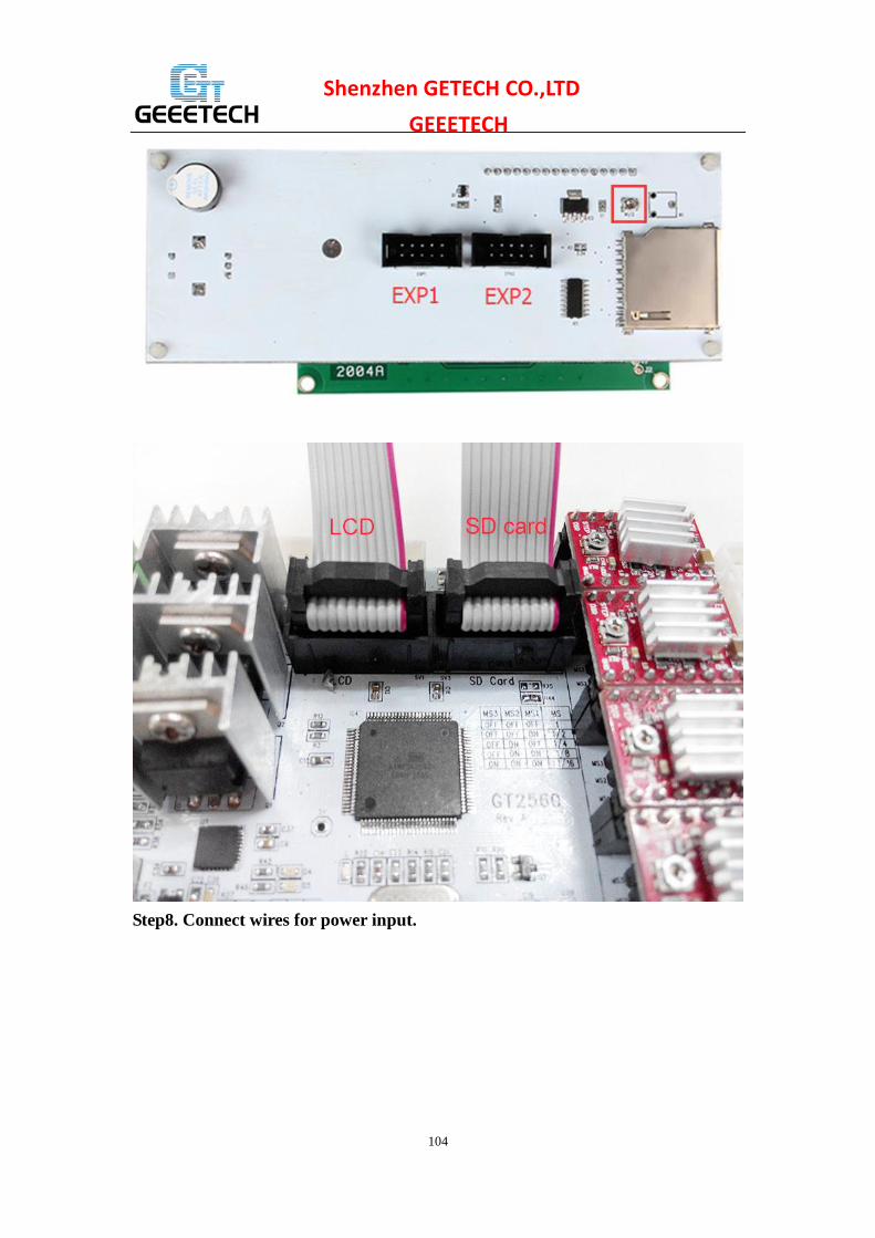
Step7. Connect wires for LCD panel.
There are two cables, one is for LCD encoder, the other is for SD card, do not connect
them reversed.
EXP1 to LCD
EXP2 to SD card
BTW, do you see the small screw above the SD card reader, if the text in of the LCD
phases in an out or there is only blocks on the screen, you can adjust this screw to
recovery it.
104
Shenzhen GETECH CO.,LTD
GEEETECH
Step8. Connect wires for power input.

105
Shenzhen GETECH CO.,LTD
GEEETECH
That is all for the wiring of GT2560.
29 Tidy out the wires.
Use the wire coil to tie put those wires together. There are holes on the acrylic plates
for the wires, you can arrange them as you like.
30 Mount the filament spool.
Pic Part ID Required number Required parts
Filament side panel
NO.27 4 M3 x 16 screw
NO.17
4 M3 square nut

106
Shenzhen GETECH CO.,LTD
GEEETECH
2 PVC tube
The whole printer assembly work is already done.
31 Tips
Before even attempting the first print it is vital that the printer is correctly calibrated.
Skipping or rushing this step will result in frustration and failed prints later, so it is
important to take the time to make sure the machine is correctly set up.
Each machine may have its own calibration procedure and this manual will not
attempt to cover all the variations. Instead here is a list of key points that should be
107
Shenzhen GETECH CO.,LTD
GEEETECH addressed.
Frame is stable and correctly aligned.
Rods are correctly aligned
Belts are taut.
Driving wheel turns smoothly
Bed is level in relation to the path of the extruder.
Filament rolls freely from the spool, without causing too much tension on the
extruder.
Current for stepper motors is set to the correct level.
Wires are correctly connected
Couplings and pulleys are fixed tightly
Firmware settings are correct including: axis movement speeds and acceleration;
temperature control; end-stops; motor directions.
Extruder is calibrated in the firmware with the correct steps per mm of filament.
The point regarding the extruder step rate is vital. Slic3r expects that the machine will
accurately produce a set amount of filament when told to do so. Too much will result
in blobs and other imperfections in the print, too little will result in gaps and poor
inter-layer adhesion. For how to set up the printer, please visit:
To know how to set up, please refer to the user manual.