Embed Size (px)
Citation preview

NOTICE OF INCORPORATIONUnited States Legal Document
≠ All citizens and residents are hereby advised that this is a legally binding document duly incorporated by reference and that failure to comply with such requirements as hereby detailed within may subject you to criminal or civil penalties under the law. Ignorance of the law shall not excuse noncompliance and it is the responsibility of the citizens to inform themselves as to the laws that are enacted in the United States of America and in the states and cities contained therein. ±
«


Standard for Elevator Suspension, Compensation, and Governor Systems
AN AMERICAN NATIONAL STANDARD
Copyright © 2010 by the American Society of Mechanical Engineers. ~ No reproduction may be made of this material without written consent of ASME. m.

INTENTIONALLY LEFT BLANK
Copyright © 2010 by the American Society of Mechanical Engm' eers. ~ E S
No reproduction may be made ofthis material without written consent of ASME. m.
Standard for Elevator Suspension, Compensation, and Governor Systems
AN AMERICAN NATIONAL STANDARD
Copyright © 2010 by the American Society of Mechanical Engineers. ~ No reproduction may be made ofthis material without written consent of ASME. ~

Date of Issuance: July 30, 2010
The next edition of this Standard is scheduled for publication in 2013. There will be no addenda issued to this edition.
ASME issues written replies to inquiries concerning interpretations of technical aspects of this Standard. The interpretations will be included with each edition. Interpretations are published on the ASME Web site under the Committee Pages at http://cstools.asme.org as they are issued.
ASME is the registered trademark of The American Society of Mechanical Engineers.
This code or standard was developed under procedures accredited as meeting the criteria for American National Standards. The Standards Committee that approved the code or standard was balanced to assure that individuals from competent and concerned interests have had an opportunity to participate. The proposed code or standard was made available for public review and comment that provides an opportunity for additional public input from industry, academia, regulatory agencies, and the public-at-Iarge.
ASME does not "approve," "rate," or "endorse" any item, construction, proprietary device, or activity. ASME does not take any position with respect to the validity of any patent rights asserted in connection with any
items mentioned in this document, and does not undertake to insure anyone utilizing a standard against liability for infringement of any applicable letters patent, nor assumes any such liability. Users of a code or standard are expressly advised that determination of the validity of any such patent rights, and the risk of infringement of such rights, is entirely their own responsibility.
Participation by federal agency representative(s) or person(s) affiliated with industry is not to be interpreted as government or industry endorsement of this code or standard.
ASME accepts responsibility for only those interpretations of this document issued in accordance with the established ASME procedures and policies, which precludes the issuance of interpretations by individuals.
No part of this document may be reproduced in any form, in an electronic retrieval system or otherwise,
without the prior written permission of the publisher.
The American Society of Mechanical Engineers Three Park Avenue, New York, NY 10016-5990
Copyright © 2010 by THE AMERICAN SOCIETY OF MECHANICAL ENGINEERS
All rights reserved Printed in U.s.A.
Copyright © 2010 by the American Society of Mechanical Engineers. ~ £ S
No reproduction may be made of this material without mitten consent of ASME. m •

CONTENTS
Foreword.............................................................................. v
Committee Roster ..................................................................... vi
Correspondence With ASME A17 Committee.................................... ....... xi
Preface
Part 1 Section 1.1 Section 1.2 Section 1.3 Section 1.4 Section 1.5 Section 1.6 Section 1.7 Section 1.8 Section 1.9 Section 1.10
xii
Stranded Carbon Steel Wire Ropes for Elevators . . . . . . . . . . . . . . . . . . . . . . . . 1 Scope ............................................................... 1 References . . . . . . . . . . . . . . . . . . . . . . . . . . . . . . . . . . . . . . . . . . . . . . . . . . . . . . . . . . . 1 Terminology . . . . . . . . . . . . . . . . . . . . . . . . . . . . . . . . . . . . . . . . . . . . . . . . . . . . . . . . . 2 Material. . . . . . . . . . . . . . . . . . . . . . . . . . . . . . . . . . . . . . . . . . . . . . . . . . . . . . . . . . . . . 7 Rope Workmanship and Finish ...................................... 8 Properties and Tolerances of Newly Constructed Rope. .. . . . . . . . .. . . . . 9 Testing And Compliance for Newly Constructed Rope . . . . . . . . . . . . . . . . 11 Ordering Information.. .. ... .. . . .. ........ .. . ... . .. . .. .. . .. .. . . ... .. . 12 Packaging and Identification ......................................... 13 Replacement Criteria ................................................ 13
Mandatory Appendix I Tables 17
Part 2 Section 2.1 Section 2.2 Section 2.3 Section 2.4 Section 2.5 Section 2.6
Section 2.7
Section 2.8 Section 2.9
Part 3
Section 3.1 Section 3.2 Section 3.3 Section 3.4 Section 3.5 Section 3.6 Section 3.7
Figures 1.3.1.1-1 1.3.1.3.2-1 1.3.1.3.2-2 1.3.1.3.3-1 1.3.1.3.4-1 1.3.1.3.4-2 1.3.1.3.4-3 1.3.1.4-1
Aramid Fiber Ropes for Elevators. . . . . . . . . . . . . . . . . . . . . . . . . . . . . . . . . . . . . . . 25 Scope............................................................... 25 References . . . . . . . . . . . . . . . . . . . . . . . . . . . . . . . . . . . . . . . . . . . . . . . . . . . . . . . . . . . 25 Terminology . . . . . . . . . . . . . . . . . . . . . . . . . . . . . . . . . . . . . . . . . . . . . . . . . . . . . . . . . 25 Material . . . . . . . . . . . . . . . . . . . . . . . . . . . . . . . . . . . . . . . . . . . . . . . . . . . . . . . . . . . . . 27 Properties and Tolerances of Newly Constructed Rope. .. . ... . . . ... .. . 27 Newly Constructed Rope Dimensions for Circular Cross-Section
Designs (Type I) .. .. .. .. . . .. . .. . . .. .. . .. . . . . . . . . . . . . . .. . . . . . . . . . . . . 28 Newly Constructed Rope Dimensions for Noncircular Cross-
Section Designs (Type II) .......................................... 28 Testing and Compliance ............................................. 28 Replacement Criteria ................................................ 29
Noncircular Elastomeric Coated Steel Suspension Members for Elevators. . . . . . . . . . . . . . . . . . . . . . . . . . . . . . . . . . . . . . . . . . . . . . . . . . . . . . . . . . . 30
Scope............................................................... 30 References . . . . . . . . . . . . . . . . . . . . . . . . . . . . . . . . . . . . . . . . . . . . . . . . . . . . . . . . . . . 30 Terminology . . . . . . . . . . . . . . . . . . . . . . . . . . . . . . . . . . . . . . . . . . . . . . . . . . . . . . . . . 30 Ma terial ...................................................... . . . . . . . 31 Properties and Tolerances ..................................... . . . . . . . 31 Testing and Compliance ............................................. 32 Replacement Criteria ................................................ 32
Elements of Stranded Steel Wire Rope .. . . . . . . . . . . . . . . . . . . . . . . . . . . . . . . 2 Round Strand ....................................................... 3 Compacted Round Strand: Before and After Compacting ............. 3 Lay Direction of Strands for Stranded Ropes ......................... 3 Seale Construction (e.g., 19S, 9-9-1) . . . . . . . . . . . . . . . . . . . . . . . . . . . . . . . . . . . 3 Warrington Construction [e.g., 19W, (6+6)-6-1] ........................ 3 Filler Construction (e.g., 25F, 12-6F-6-1) . . . . . . . . . . . . . . . . . . . . . . . . . . . . . . . 3 Examples of Cores .. . . . . . . . . . . . . . . . . . . . . . . . . . . . . . . . . . . . . . . . . . . . . . . . . . 4
iii
Copyright © 2010 by the American Society of Mechanical Engineers. No reproduction may be made of this material without written consent of ASME.
~ ~

1.3.2.4.2-1 1.3.3.1.1-1 1.3.3.2.1-1 1.3.3.2.2-1
Tables 1.4.1-1 1.4.1.1-1 1.4.1.1-2 1.6.4.1-1
1.6.4.1-2
1.6.6.1.1-1
1.6.6.1.1-2
1.6.6.1.2-1
1.8.1-1 1.10.1.2-1 1.10.3-1 2.4.1.1-1 2.4.1.1-2 2.6.2-1 2.7.2-1 3.5.7-1
Regular (Ordinary) Lay and Lang Lay ........................... " .. . 5 Diameter of Round Rope ............................................ 5 Strand Lay Length . . . . . . . . . . . . . . . . . . . . . . . . . . . . . . . . . . . . . . . . . . . . . . . . . . . 5 Rope Lay Length .................................................... 6
Wire Level or Tensile Strength Grades for Given Rope Grades ........ 7 Wire Level or Tensile Strength Grade Requirements . . . . . . . . . . . . . . . . . . . 8 Wire Torsion Requirements .......................................... 8 Weight of Coating for Final-Galvanized or Final-Coated
Zn-5AI-MM Rope Wire for Newly Constructed Rope ............... 10 Weight of Coating for Drawn-Galvanized or Drawn-Coated
Zn-5AI-MM Rope Wire for Newly Constructed Rope ............... 10 Tolerances on Rope Diameter (Stranded Rope) for Newly
Constructed Rope With Cores of Fiber or Other Nonmetallic Ma terials . . . . . . . . . . . . . . . . . . . . . . . . . . . . . . . . . . . . . . . . . . . . . . . . . . . . . . . . . . 10
Tolerances on Rope Diameter (Stranded Rope) for Newly Constructed Rope With Steel or Steel-Based Composite Cores ...... 11
Permissible Differences in Rope Diameter for Newly Constructed Rope.............................................................. 11
Ordering Information ..................... " .................... " .. . 13 Wire Breaks: Crown Wire Breaks Per Lay Length ..................... 14 Minimum Diameter ................................................. 15 Nominal Aramid Yarn Property Values. .. ... . .. ... .. .. .. . .. .. . .. .. ... 27 Aramid Resin Impregnated Strand Property Values. . . . . .. .... . .. .. .. . 27 Tolerances on Diameter .............................................. 28 Tolerances on Dimensions ........................................... 29 Tolerances on Nominal Noncircular Elastomeric Coated Steel
Suspension Member Sizes ......................................... 32
Nonmandatory Appendix A Inspection and Replacement of Steel Wire Ropes 35
iv
Copyright © 2010 by the American Society of Mechanical Engineers. No reproduction may be made of this material without written consent of ASME.

FOREWORD
This is the first edition of a Standard for elevator suspension and compensation systems as well as ropes for governor applications. This Standard has been developed by the American Society of Mechanical Engineers (ASME) to provide guidance to the elevator industry for the appropriate use of means for suspension, compensation, and governors. The first edition includes standards for three technologies for elevators, namely: steel wire ropes, aramid fiber ropes, and noncircular elastomeric coated steel suspension members. Uniform standards for these important items are necessary to ensure consistent levels of safety and to provide guidance for the manufacturers of these items as well as the designers, manufacturers, installers, maintainers, and inspectors of elevator equipment.
As other technologies emerge and are deemed to be suitable for similar applications, this Standard will be expanded to include criteria for their usage.
In developing this Standard, experts were assembled from the steel wire rope, aramid fiber rope, and noncircular elastomeric coated steel suspension members engineering and manufacturing fields. Relevant existing standards were studied during the development of this Standard and are referenced where appropriate. The scope of this Standard covers North American and international requirements in a comprehensive manner and does not conflict with existing American or international standards. This Standard is intended to be used in conjunction with the AS ME A17.1/CSA B44, Safety Code for Elevators and Escalators, and related Codes and standards.
Steel Wire Rope for Elevators
Steel wire rope has been used for many years in the elevator industry, for suspension, compensation, and governor applications.
Due to the large range of applications in this diverse market, many variations of steel wire ropes are in current use. Examples include rope of regular and lang lay, left and right lay, preformed and nonpreformed. Such ropes may be of a variety of wire materials, from iron to high tensile steel and may be of corrosion resistant construction. Various core materials including natural and synthetic fiber and steel may also be used. Nominal imperial dimensions as well as SI dimensional ropes are used.
v
In recognition of the importance of this vital elevator component and the unique practices of the North American industry, this Standard was developed. This Standard covers the current applications and provides strength and material criteria as well as testing, compliance, inspection, replacement, and ordering information. Imperial and SI dimensions are addressed in the Standard. The purpose of this Standard is to enhance public safety and to provide guidance to manufacturers and users of steel wire rope.
Aramid Fiber Ropes and Elastomeric Coated Steel Belts
With the appearance in the market place of new suspension and compensation means technologies, such as aramid fiber ropes and noncircular elastomeric coated steel suspension members for elevators, the need for standards that will ensure the safe application of these items became evident. This Standard addresses these important technologies.
In developing the standards, extensive test results were studied and the properties and durability of the new suspension and compensation means were examined. The work included visits to major laboratories at which all aspects of the non circular elastomeric coated steel suspension members were tested.
The work included a visit to the factory of a major manufacturer of aramid fiber and technical presentations by experts in this technology. The test work of a major laboratory and field results from the application of aramid fiber rope on elevators were also studied.
Test facilities where the noncircular elastomeric coated steel suspension members were extensively tested on elevators were also visited. In addition, technical presentations on the noncircular elastomeric coated steel suspension members regarding their construction and testing took place.
Tests on both ramid fiber ropes and noncircular elastome ric coated steel suspension members included life, durability, resistance to damage, traction, replacement criteria, effects of the environment, and many other criteria. This work was extremely helpful in developing the standards and building confidence in the validity of the req uirements.
ASME A17.6-2010 was approved by the American National Standards Institute on March 17, 2010.
Copyright © 2010 by the American Society of Mechanical Engineers. No reproduction may be made of this material without written consent of ASME.

ASME A17 ELEVATOR AND ESCALATOR COMMITTEE
STANDARDS COMMITTEE
J. w. Coaker, Chair N. B. Martin, Vice Chair H. E. Pee lie III, Vice Chair G. A. Burdeshaw, Staff Secretary E. V. Baker, IUEC T. D. Barkand, U.S. Department of Labor R. E. Baxter, Baxter Residential Elevators K. S. Lloyd, Jr., Alternate, Abell Elevator International L. Bialy, Otis Elevator Co. N. E. Marchitto, Alternate, Otis Elevator Co. B. D. Black, BDBlack Codes, Inc. J. R. Brooks, North Carolina Department of Labor J. W. Adams, Alternate, Kone, Inc. J. W. Coaker, Coaker & CO. J. Filippone, Port Authority of New York and New Jersey J. H. Humphrey, Alternate, Port Authority of New York and New
Jersey c. C. Fox, Rainbow Security Control Ltd. G. W. Gibson, George W. Gibson & Associates, Inc. R. A. Gregory, Vertex Corp. R. F. Hadaller, Technical Standards and Safety Authority M. Tevyaw, Alternate, Technical Standards andSafety Authority P. Hampton, ThyssenKrupp Elevator J. T. Herrity, U.S. Department of the Navy A. P. Juhasz, Kone, Inc. D. A. Kalgren, Kane, Inc. D. S. Boucher, Alternate, Kone, Inc. G. A. Kappenhagen, Schindler Elevator Corp. J. W. Koshak, Elevator Safety Solutions, Inc. H. Simpkins, Alternate, ThyssenKrupp Elevator Co. N. B. Martin, Department of Commerce, State of Ohio Z. R. McCain, Jr., McCain Engineering Associates, Inc. M. V. Farinola, Alternate, MV Farinola, Inc. D. A. McColl, Otis Canada, Inc. H. E. Peelle III, Peelle Co. S. P. Reynolds, Alternate, Peelle Co. A. Rehman, Schindler Elevator Corp. V. P. Robibero, Schindler Elevator Corp. C. W. Rogier, State of Michigan R. L. Seymour, Robert L. Seymour & Associates, Inc. R. S. Seymour, Alternate, Robert L. Seymour & Associates, Inc. J. H. Shull, J.H. Shull Engineering D. M. Stan laske, NAESA International D. L. Steel, David L. Steel Escalators D. L. Turner, Davis L. Turner & Associates R. S. Caporale, Alternate, Elevator World, Inc. A. H. Verschell, Dwan Elevator D. M. Winkle, Sr., IUEC Local #14 G. W. Kosinski, Alternate, EIWPF D. A. Witham, GAL Manufacturing Corp.
Oanuary 2010)
vi
Ex Officio Members G. A. Burdeshaw, Staff
Secretary R. E. Baxter L. M. Capuano G. W. Gibson G. A. Kappenhagen M. Martin
H. E. Peelle III J. B. Peskuski J. H. Shull D. L. Steel M. Tevyaw M. R. Tilyou A. H. Verschell
Honorary Committee G. A. Burdeshaw, Staff
Secretary L. J. Blaiotta E. A. Donoghue B. J. Fanguy H. E. Godwin, Jr.
C. E. Hempel C. L. Kort A. A. Mascone E. M. Philpot R. L. Rogers L. E. White
Regulatory Advisory Council N. B. Martin, Chair J. R. Brooks, Vice Chair G. A. Burdeshaw, Staff
Secretary J. L. Borwey, Secretary G. Antona J. H. Burpee A. L. Caine J. R. Calpini P. Caploon J. Day N. C. Dimitruck M. Dorosk L. A. Giovannetti J. M. Gould A. N. Griffin R. F. Hadaller S. J. Hickory D. Holmes
I. D. Jay L. C. Kanicki C. C. Mann M. J. Mellon, Jr. I. D. Mercer S. Mercier K. P. Morse M. E. Pedersen M. R. Poulin J. P. Roche C. W. Rogier D. M. Stanlaske S. F. Stout L. M. Taylor L. E. Watson W. C. Watson W.J. Witt D. Melvin, Alternate C. D. Wagner, Alternate
Copyright © 2010 by the American Society of Mechanical Engineers. ~ ~ No reproduction may be made of this material without \Witten consent of ASME.
NATIONAL INTEREST REVIEW COMMITTEE G. A. Burdeshaw, Staff B. H. Larson
Secretary M. A. Malek J. P. Andrew J. J. Mancuso R. J. Blatz C. C. Mann J. E. Brannon N. E. Marchitto M. T. Brierley D. Mason B. B. Calhoun J. L. Meyer J. A. Caluori T. S. Mowrey C. S. Carr F. G. Newman M. A. Chavez J. W. O'Boyle R. F. Dieter J. J. O'Donoghue B. Faerber B. Peyton
J. G. Gerk M. J. Pfeiffer L. A. Giovannetti M. R. Poulin J. M. Gould P. M. Puno N. R. Herchell L. S. Rigby
J. E. Herwig J. R. Runyan J. M. Imgarten R. D. Schloss J. Inglis S. Shanes T. Isaacs J. L. Stabler F. A. Kilian D. M. Stanlaske M. L. Lane D. A. Swerrie W. R. Larsen
B44.1/Al?5 ELEVATOR AND ESCALATOR ELECTRICAL EQUIPMENT COMMITTEE
J. H. Shull, Chair M. L. Hite, Vice Chair M. Dodd, Secretary G. A. Burdeshaw. Staff
Secretary P. D. Barnhart
J. W. Blain A. D. Brown
J. Caldwell
J. L. Della Porta
B. T. Irmacher
J. Lee R. A. Mackenzie P. F. McDermott M. Mihai V. M. Todt J. M. Weber D. A. Donner, Alternate M. L. Jaremko, Alternate
J. M. Weber. Alternate
Al? CODE COORDINATION COMMITTEE B. D. Black. Chair G. A. Burdeshaw. Staff
Secretary L. Bialy R. Bukowski P. Caploon
R. Cote G. W. Gibson
G. A. Kappenhagen J. W. Koshak B. Tubbs K. Paarlberg. Alternate
DUMBWAITER AND ATD COMMITTEE J. B. Peskuski, Chair
R. Mohamed, Staff Secretary S. S. Duquaine
R. A. Gregory
K. Holdcraft
B. P. McCune J. W. Ninness D. Witt
EARTHQUAKE SAFETY COMMITTEE G. W. Gibson, Chair M. J. Smith, Vice Chair A. B. Byk, Staff Secretary B. Blackaby R. P. Lorenzo
J. L. Meyer
W. C. Ribeiro J. K. Ruth W. C. Schad rack
A. J. Schiff A. J. Shelton D. A. Kalgren, Alternate
vii
EDITORIAL COMMITTEE D. McColl, Chair
G. A. Burdeshaw, Staff Secretary
B. D. Black
J. Filippone
ELECTRICAL COMMITTEE A. P. Juhasz, Chair B. Blackaby, Vice Chair J. D. Busse, Vice Chair D. R. Sharp, Staff Secretary T. D. Barkand P. D. Barnhart
S. H. Benjamin J. W. Blain
J. Caldwell B. C. Castillo
J. P. Donnelly R. E. Droste R. Elias S. E. Fisher G. N. Henry Y. C. Ho N. E. Marchitto
P. F. McDermott T. G. Moskal A. L. Peck D. K. Prince P. M. Puno V. P. Robibero
M. Stergulc D. Alley, Alternate J. c. Carlson, Alternate J. L. Della Porta, Alternate
R. L. Frazier, Alternate D. Henderson, Alternate M. Miha, Alternate J. C. Ramos, Alternate J. P. Rennekamp, Alternate J. H. Shull, Alternate J. M. Weber, Alternate
ELEVATORS USED FOR CONSTRUCTION COMMITTEE N. B. Martin, Chair
G. A. Burdeshaw, Staff Secretary
R. E. Baxter
c. C. Fox R. A. Gregory J. R. Quackenbush C. W. Rogler
EMERGENCY OPERATIONS COMMITTEE M. Martin, Chair A. Rehman, Vice Chair
A. B. Byk, Staff Secretary M. Abbott J. Beamish D. R. Beste B. D. Black M. T. Brierley
M. W. Bunker, Jr. P. Caploon G. B. Cassini D. Cook R. B. Fraser
D. Henderson D. Holmes
S. R. James C. Koenig
J. Latham D. McColl C. H. Murphy
T. F. Norton J. J. O'Donoghue
B. F. O'Neill D. K. Prince L. F. Richardson V. Selektor
R. L. Seymour M. Tevyaw
D. Warne D. J. Winslow D. A. Witham J. C. Carlson, Alternate R. F. Hadaller, Alternate
H. Ickes, Alternate J. K. O'Donnell, Alternate
G. Rees, Alternate R. Reiswig, Alternate
R. J. Roux, Alternate J. Varon, Alternate
Copyright © 2010 by the American Society of Mechanical Engineers. ~ ~ No reproduction may be made of this material without written consent of ASME.

ESCALATOR AND MOVING WALK COMMITTEE D. l. Turner, Chair T. R. Nurnberg, Vice Chair R. Mohamed, Staff Secretary P. E. A. Burge D. R. Evans
J. Filippone J. G. Gerk R. A. Glanzmann P. l. Hackett K. M. Harris H. A. Hausmann R. Herndobler J. A. Kinahan C. Milley T. G. Moskal
J. D. Shupe K. J. Smith D. l. Steel P. Velasquez, Jr. P. J. Welch D. Winkelhake C. Anayiotos, Alternate C. S. Carr, Alternate K. G. Hamby, Alternate T. P. Kenny, Alternate A. Rehman, Alternate D. E. Rush, Alternate J. C. Steele, Alternate J. E. Tyler, Alternate
EVACUATION GUIDE COMMITTEE D. l. Turner, Chair R. S. Seymour, Vice Chair G. A. Burdeshaw, Staff
Secretary J. R. Brooks
D. Cook C. C. Fox J. l. Meyer J. J. O'Donoghue C. W. Rogler
EXISTING INSTALLATIONS COMMITTEE D. B. Labrecque, Chair A. B. Byk, Staff Secretary R. E. Baxter
J. Bera J. H. Butler J. D. Carlisle, Jr. G. B. Cassini
C. J. Duke A. T. Gazzaniga
J. G. Gerk R. A. Gregory J. T. Herrity J. A. Jaudes R. Kremer K. S. Lloyd, Jr. G. M. Losey Z. R. McCain, Jr.
D. McColl P. McPartland N. R. Mistry R. C. Morrical G. l. Nyborg III S. A. Quinn J. S. Rearick A. J. Saxer G. Stiffler H. M. Vyas T. Waardenburg P. J. Welch l. E. White C. Buckley, Alternate V. P. Robibero, Alternate M. Strachan, Alternate S. Swett, Alternate
HAND AND SIDEWALK ELEVATOR COMMITTEE R. S. Caporale, Chair G. A. Burdeshaw, Staff
Secretary V. G. Bahna J. Doyle
J. Duffy
G. Greenberg H. J. Macuga N. J. Montesano G. West J. P. Merkel, Alternate
viii
HOISTWAY COMMITTEE l. M. Capuano, Chair D. McColl, Vice Chair A. B. Byk, Staff Secretary B. D. Black l. J. Blaiotta D. S. Boucher F. R. Cooper
G. W. Gibson H. J. Gruszynski R. F. Hadaller J. l. Harding E. A. Heath III D. Holmes D. P. Kraft K. H. Lewis G. Nuschler H. Peelle III
R. Phillips R. Quinlan F. Regalado A. Rehman S. P. Reynolds H. Simpkins D. Warne
D. A. Witham w. Ziegert L. Bialy, Alternate A. S. Conkling, Alternate M. P. Lamb, Alternate R. K. leckman, Alternate W. M. Miller, Alternate M. Tevyaw, Alternate K. Uerling, Alternate J. Varon, Alternate
HYDRAULIC COMMITTEE G. A. Kappenhagen, Chair M. G. Miller, Vice Chair G. A. Burdeshaw, Staff
Secretary l. Bialy P. E. A. Burge C. C. Fox H. A. Hammerstrom C. B. Jackson
A. Jahn T. S. Mowrey l. S. Rigby
c. W. Rogler J. N. Rouse III W. M. Shrum, Jr. H. Simpkins B. Giddens, Alternate, K. A. Grunden, Alternate J. A. Kennedy, Alternate J. W. Koshak, Alternate A. M. McClement, Alternate S. S. Pearson, Alternate A. Rehman, Alternate J. L. Shrum, Alternate
INCLINED ELEVATOR COMMITTEE A. H. Verschell, Chair G. A. Burdeshaw, Staff
Secretary
J. R. Carrick J. T. Herrity T. l. Pope
INSPECTIONS COMMITTEE M. Tevyaw, Chair J. Filippone, Vice Chair R. Mohamed, Staff Secretary G. Antona C. Archer R. E. Baxter
J. R. Brooks J. W. Coaker M. V. Farinola H. S. Frank R. F. Hadaller P. Hampton
J. T. Herrity l. C. Kanicki J. J. Knolmajer G. W. Kosinski K. S. Lloyd, Jr.
Z. R. McCain, Jr. J. S. Rearick C. W. Rogler J. D. Rosenberger J. R. Runyan R. D. Schloss R. S. Seymour R. D. Shepherd W. M. Snyder D. M. Stanlaske J. Strzelec D. Warne
P. G. Bender, Alternate M. Boutin, Alternate D. McLellan, Alternate S. Swett, Alternate
Copyright © 2010 by the American Society of Mechanical Engineers. ~ .. No reproduction may be made of this material without written consent of ASME. ~

INTERNATIONAL STANDARDS COMMITTEE G. W. Gibson, Chair L. Bialy, Vice Chair G. A. Burdeshaw, Staff
Secretary B. D. Black B. Blackaby R. S. Caporale J. W. Coaker J. T. Herrity A. P. Juhasz
G. A. Kappenhagen J. W. Koshak J. A. Popp V. P. Robibero D. M. Stanlaske J. Strzelec D. L. Turner V. Q. Bates, Alternate T. Derwinski, Alternate D. R. Evans, Alternate
lIMITED-USE/liMITED-APPLICATION ELEVATOR COMMITTEE
R. E. Baxter, Chair D. C. Balmer, Vice Chair M. L. Vazquez, Staff
Secretary K. Brinkman P. Chance C. C. Fox P. W. lackler M. L. McDonald
s. J. Mehalko J. L. Mickel C. H. Murphy R. Murphy J. P. Schumacher A. H. Verschell R. B. Weber D. M. Winkle, Jr. M. B. Hays, Alternate
MAINTENANCE, REPAIR, AND REPLACEMENT COMMITTEE
Z. R. McCain, Jr., Chair R. A. Gregory, Vice Chair A. B. Byk, Staff Secretary R. E. Baxter G. B. Cassini J. J. Delorenzi C. J. Duke M. V. Farinola J. Filippone J. G. Gerk S. P. Greene R. F. Hadaller R. E. Haukeness J. T. Herrity A. S. Hopkirk J. A. Jaudes J. J. Knolmajer R. Kremer D. B. Labrecque P. W. lackler B. H. larson K. S. Lloyd, Jr.
G. M. Losey D. McColl P. J. McPartland N. R. Mistry R. C. Morrical J. Murphy W. B. Pletch J. R. Quackenbush T. Quinn J. S. Rearick A. Rehman V. P. Robibero A. J. Saxer R. D. Schloss R. D. Shepherd J. Strzelec H. M. Vyas T. Waardenburg C. Buckley, Alternate D. Keller, Alternate J. L. Stabler, Alternate
MARINE ELEVATOR COMMITTEE M. R. Tilyou, Chair G. A. Burdeshaw, Staff
Secretary E. J. Crawford
W. D. George T. J. Ingram R. Wagner
ix
MECHANICAL DESIGN COMMITTEE G. W. Gibson, Chair L. Bialy. Vice Chair D. L. Turner, Vice Chair A. B. Byk, Staff Secretary K. A. Apperson E. V. Baker R. J. Bolen C. C. Fox H. S. Frank R. F. Hadaller D. K. Kaczmarek D. A. Kalgren K. Konyar J. W. Koshak R. Kremer M. P. lamb
M. L. lane T. G. Moskal A. Rehman M. Rhiner H. Simpkins C. E. Vlahovic R. J. Walker S. P. Wurth R. E. Creak, Alternate D. P. Kraft, Alternate R. K. leckman, Alternate W. C. Ribeiro, Alternate W. C. Schad rack III,
Alternate P. Winey, Alternate
MINE ELEVATOR COMMITTEE T. D. Barkand, Chair A. B. Byk, Staff Secretary C. D. Barchet R. M. Bates W. M. Dietz P. E. Fernatt M. G. Katich J. B. Ketchem A. L. Martin
N. B. Martin G. L. Miller H. E. Newcomb A. J. Saxer D. J. Shook R. L. Sidwell M. P. Snyder J. K. Taylor
NEW TECHNOLOGY COMMITTEE J. W. Coaker, Chair G. A. Burdeshaw, Staff
Secretary M. H. Bayyari L. Bialy B. D. Black A. D. Brown A. D. Byram R. S. Caporale L. M. Capuano M. Dodd G. W. Gibson A. N. Griffin I. D. Jay A. P. Juhasz
L. C. Kanicki R. M. Kennedy J. W. Koshak G. W. Kosinski R. H. laney K. S. Lloyd, Jr. D. McColl M. Mihai M. Pedram V. P. Robibero D. M. Stanlaske D. L. Turner R. E. Baxter, Alternate M. Chan, Alternate
Copyright © 2010 by the American Society of Mechanical Engineers. No reproduction may be made of this material without written consent of ASME.

RACK AND PINION AND SPECIAL PURPOSE PERSONNEL ELEVATOR COMMITTEE
A. J. Marchant, Chair K. M. Harrison, Vice Chair
S. Harris, Secretary G. A. Burdeshaw, Staff
Secretary D. F. Grund
R. E. Haukeness J. W. Koshak R. C. Meiresonne B. L. O'Neill P. J. Welch J. A. Harrison, Alternate
x
RESIDENCE ELEVATOR COMMITTEE A. H. Verschell, Chair
K. Brinkman, Vice Chair M. L. Vazquez, Staff
Secretary D. C. Balmer
R. E. Baxter R. G. Buonora
P. Chance D. J. Degere P. Edwards R. Elias P. Giannis M. J. Holat S. D. Holat C. S. Jone P. W. Lackler
K. H. Lewis M. Lewis
J. c. Lund M. L. McDonald W. M. McKinley
S. J. Mehalko J. L. Mickel
W. M. Middleton R. J. Murphy
T. L. Pope J. P. Schumacher S. S. Duquaine, Alternate M. B. Hays, Alternate
J. B. Peskuski, Alternate
Copyright © 2010 by the American Society of Mechanical Engineers. No reproduction may be made of this material without written consent of ASME.

CORRESPONDENCE WITH ASME All COMMITTEE
ASME codes and standards are developed and maintained with the intent to represent the consensus of concerned interests. As such, users of this and other ASME A17 codes and standards may interact with the committee by requesting interpretations, proposing revisions, and attending committee meetings. Correspondence should be addressed to:
Secretary, A17 Standards Committee The American Society of Mechanical Engineers Three Park Avenue New York, NY 10016 E-mail: infocentralasme.org
All correspondence to the Committee must include the individual's name and post office address in case the Committee needs to request further information.
Proposing Revisions. Revisions are made periodically to the Code to incorporate changes that appear necessary or desirable, as demonstrated by the experience gained from the application of the procedures, and in order to conform to developments in the elevator art. Approved revisions will be published periodically.
The Committee welcomes proposals for revisions to this Code. Such proposals should be as specific as possible: citing the Section number(s), the proposed wording, and a detailed description of the reasons for the proposal including any pertinent documentation.
Requesting Interpretations. On request, the A17 Committee will render an interpretation of any requirement of the Code. Interpretations can only be rendered in response to a written request sent to the Secretary of the Standards Committee.
The request for interpretation should be clear and unambiguous. It is further recommended that the inquirer submit his request utilizing the following format:
Subject: Cite the applicable Section number(s) and a concise description. Edition: Cite the applicable edition and supplement of the Code for which the interpretation
is being requested. Question: Phrase the question as a request for an interpretation of a specific requirement
suitable for general understanding and use, not as a request for an approval of a proprietary design or situation. The question shall be phrased, where possible, to permit a specific "yes" or "no" answer. The inquirer may also include any plans or drawings that are necessary to explain the question; however, they should not contain proprietary names or information.
Requests that are not in this format will be rewritten in this format by the Committee prior to being answered, which may inadvertently change the intent of the original request.
ASME procedures provide for reconsideration of any interpretation when or if additional information that might affect an interpretation is available. Further, persons aggrieved by an interpretation may appeal to the cognizant AS ME committee or subcommittee. ASME does not "approve," "certify," "rate," or "endorse" any item, construction, proprietary device, or activity.
Attending Committee Meetings. The A17 Standards Committee and the various Working Committees regularly hold meetings all of which are open to the public. Persons wishing to attend any meeting should contact the Secretary of the Standards Committee.
xi
Copyright © 2010 by the American Society of Mechanical Engineers. No reproduction may be made of this material without written consent of ASME.
~ ~

PREFACE
GENERAL
This is one of many standards developed by the American Society of Mechanical Engineers (ASME) under the general auspices of the American National Standards Institute (ANSI). Safety codes and standards are intended to enhance public health and safety. Revisions result from committee consideration of factors such as technological advances, new data, and changing environmental and industry needs. Revisions do not imply that previous editions were inadequate.
This Standard is referenced by and intended to be used in conjunction with ASME A17.I/CSA B44, Safety Code for Elevators and Escalators, and related Codes and standards. Written inquiries regarding this Standard should be addressed to the Secretary of the ASME A17 Standards Committee.
NOTE: Referenced Codes, Standards, and Test Methods that appear with no date indicated shall be the edition in effect at the time of publication of this Standard.
FORM AND ARRANGEMENT
This Standard consists of three parts, each covering a specific technology related to elevator suspension and compensation means and governor ropes. The Foreword, Preface, and Notes that are included in this document, and the Interpretations that are provided as a separate document are not part of this American National Standard. They are advisory in nature and are intended for clarification only.
SCOPE
This Standard covers the means and members of suspension, compensation, and governor systems for elevators within the scope of ASME AI7.I/CSA B44.
xii
NOTE: It must be determined by the individual working committees as to the level of appropriateness of applying the New Technologies in their particular applications.
This Standard includes the material properties, design, testing, inspection, and replacement criteria for these means. It includes the requirements for steel wire rope, aramid fiber rope, and noncircular elastomeric coated steel suspension members, and provides direction for future constructions as new technology develops.
INTRODUCTION
This Standard is intended to be used with ASME A17.I/CSA B44, Safety Code for Elevators and Escalators, AI7.2, Guide for the Inspection of Elevators, Escalators, and Moving Walks, and A17.3, Safety Code for Existing Elevators and Escalators, and other Codes and Standards referenced by these Standards as well as other related Standards.
The ASME AI7.I/CSA B44 Code specifically references the suspension and compensation means and governor systems covered by this Standard. This Standard was developed to provide safe, consistent criteria for steel wire rope, aramid fiber rope, noncircular elastomeric coated steel suspension members and other means of suspension and compensation used in the Elevator Industry.
Part 1 covers steel wire rope. Part 2 covers aramid fiber rope. Part 3 covers noncircular elastomeric coated steel sus
pension members. The Standard is under the auspices of the ASME AI7.I
Standards Committee and is subject to the operating procedures of this Committee.
Copyright © 2010 by the American Society of Mechanical Engineers. No reproduction may be made ofthis material without written consent of ASME.

ASME A17.6-2010
STANDARD FOR ELEVATOR SUSPENSION, COMPENSATION, AND GOVERNOR SYSTEMS
Part 1 Stranded Carbon Steel Wire Ropes for Elevators
SECTION 1.1 SCOPE
Part 1 covers the general requirements for the more common types of stranded steel wire ropes for hoisting, compensation, and governor applications on passenger or freight elevators. Included in the scope of this Part are steel wire ropes in various grades and constructions from 4 mm to 38 mm (~2 in. to 1)j in.) manufactured from uncoated wire or metallic coated wire. For specific applications, additional or alternative requirements may apply, provided equivalent safety is maintained.
Part 1 covers regular lay and lang lay, preformed and nonpreformed elevator rope in nominal imperial dimensions as well as SI dimensions. Various constructions of steel wire rope are covered, i.e., Seale, Warrington, and Filler. Part 1 covers the broad range of wire materials in current use including Iron, Traction, Extra High Strength Traction, 1570 Single, 1180/1770 Dual, 1370/1770 Dual, 1770 Single, 1960 Single, and 2300 Single. Various rope core materials in current use are covered by this Part including natural and synthetic fiber cores and steel cores. This Part covers ropes made from uncoated wires or metallic coated wires (e.g., galvanized). This Part includes criteria for testing and compliance of rope, replacement of rope, and ordering information for steel wire rope.
NOTE: Part 1 is written in the combined format, presenting requirements for rope products in both Imperial units, utilized historically in the SI and U.S. Customary units as recognized by current international standards. The values stated in SI (metric) units or Imperial units are to be regarded separately. The values are not exact equivalents; therefore, each system must be used independently of the other.
SECTION 1.2 REFERENCES
Part 1 incorporates, by dated or undated reference, provisions from other publications. These normative references are cited at their appropriate place in the text, and the publications are listed. For dated references,
subsequent amendments to or revisions of any of these publications apply to this Part only when incorporated by amendment or revision. For undated references, the latest edition would apply.
1.2.1 ASTM Standards
ASTM A 931-2008, Standard Test Method for Tension Testing of Wire Ropes and Strand
ASTM A 1007-2000, Standard Specification for Carbon Steel Wire for Wire Rope
ASTM A 1023-2002, Specification for Stranded Carbon Steel Wire Ropes for General Purposes
Publisher: American Society for Testing and Materials (ASTM), 100 Barr Harbor Drive, West Conshohocken, PA 19428-2959 (www.astm.org)
1.2.2 ISO Standards
ISO 2020-1:1997, Aerospace - Preformed flexible steel wire rope for aircraft controls - Part 1: Dimensions and loads
ISO 2232:1990, Round drawn wire for general purpose non-alloy steel wire ropes - Specifications
ISO 3108:1974, Steel wire ropes for general purposesdetermination of actual breaking load
ISO 4101:1983, Drawn steel wire for elevator ropes -Specifications
ISO 4344:2004, Steel wire ropes for lifts - Minimum requirements
ISO 4345:1988, Steel wire ropes - Fibre main cores -Specifica tion
ISO 4346:1977, Steel wire ropes for general purposesLubricants - Basic requirements
ISO 9001, Quality management systems - Requirements
Publisher: International Organization for Standardization (ISO), 1 ch. de la Voie-Creuse, Case postale 56, CH-1211, Geneve 20, Switzerland/Suisse (www.iso.org)
Copyright © 2010 by the American Society of Mechanical Engineers. ~ ~ No reproduction may be made of this material without written consent of ASME.
ASME A17.6-2010
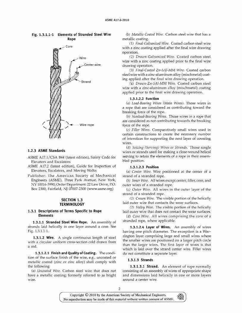
Fig. 1.3.1.1-1 Elements of Stranded Steel Wire Rope
1.2.3 ASME Standards
ASME A17.1/CSA B44 (latest edition), Safety Code for Elevators and Escalators
ASME A17.2 (latest edition), Guide for Inspection of Elevators, Escalators, and Moving Walks
Publisher: The American Society of Mechanical Engineers (ASME), Three Park Avenue, New York, NY 10016-5990; Order Department: 22 Law Drive, P.O. Box 2300, Fairfield, NJ 07007-2300 (www.asme.org)
SECTION 1.3 TERMINOLOGY
1.3.1 Descriptions of Terms Specific to Rope Elements
1.3.1.1 Stranded Steel Wire Rope. An assembly of strands laid helically in one layer around a core. See Fig. 1.3.1.1-1.
1.3.1.2 Wire. A single continuous length of steel wi th a circular uniform cross-section cold drawn from a rod.
1.3.1.2.1 Finish and Quality of Coating. The condition of the surface finish of the wire, e.g., uncoated or metallic coated (zinc or zinc alloy) shall comply with the following:
(a) Uncoated Wire. Carbon steel wire that does not have a metallic coating; formerly referred to as bright wire.
2
(b) Metallic Coated Wire. Carbon steel wire that has a metallic coating.
(1) Final-Galvanized Wire. Coated carbon steel wire with a zinc coating applied after the final wire drawing operation.
(2) Drawn-Galvanized Wire. Coated carbon steel wire with a zinc coating applied prior to the final wire drawing operation.
(3) Final-Coated Zn-SAl-MM Wire. Coated carbon steel wire with a zinc-aluminum alloy (mischmetal) coating applied after the final wire drawing operation.
(4) Drawn-Zn-SAl-MM Wire. Coated carbon steel wire with a zinc-aluminum alloy (mischmetal) coating applied prior to the final wire drawing operation.
1.3.1.2.2 Function (a) Load-Bearing Wires (Main Wires). Those wires in
a rope that are considered as contributing toward the breaking force of the rope.
(b) Nonload-Bearing Wires. Those wires in a rope that are considered as not contributing towards the breaking force of the rope.
(c) Filler Wires. Comparatively small wires used in certain constructions to create the necessary number of interstices for supporting the next layer of covering wires.
(d) Seizing (Serving) Wires or Strands. Those single wires or strands used for making a close-wound helical serving to retain the elements of a rope in their assembled position.
1.3.1.2.3 Position (a) Center Wire. Wire positioned at the center of a
strand of a stranded rope. (b) Inner Wire. All wires except center, filler, core, and
outer wires of a stranded rope. (c) Outer Wire. All wires in the outer layer of the
strand of a stranded rope. (1) Crown Wire. The visible portion of the helically
laid outer wire that contacts the wear surfaces. (2) Valley Wire. The visible portion of the helically
laid outer wire that does not contact the wear surfaces. (d) Core Wire. All wires comprising the core of a
stranded rope, where applicable.
1.3.1.2.4 Layer of Wires. An assembly of wires having one pitch diameter. The exception is a Warrington layer comprising large and small wires where the smaller wires are positioned on a larger pitch circle than the larger wires. The first layer of wires is that which is laid over the strand center wire. Filler wires do not constitute a separate layer.
1.3.1.3 Strands
1.3.1.3.1 Strand. An element of rope normally consisting of an assembly of wires of appropriate shape and dimensions laid helically in one or more layers around a center wire.
Copyright © 2010 by the American Society of Mechanical Engineers. ~ €m~ No reproduction may be made of this material without written consent of ASME. ~

ASME A17.6-2010
Fig. 1.3.1.3.2-1 Round Strand
Fig. 1.3.1.3.2-2 Compacted Round Strand: Before and After Compacting
(a) Before (b) After
Fig. 1.3.1.3.3-1 lay Direction of Strands for Stranded Ropes
1.3.1.3.2 Shape of Cross-Section (a) Round Strand. Strand having a perpendicular
cross-section that is approximately the shape of a circle. See Fig. 1.3.1.3.2-1.
(b) Compacted Round Strand. A round strand that has been subjected to a compacting process such as drawing, rolling, or swaging. See Fig. 1.3.1.3.2-2.
1.3.1.3.3 Strand lay Direction. The direction right (z) or left (s) corresponding to the direction of lay of the outer wires in relation to the longitudinal axis of the strand. See Fig. 1.3.1.3.3-1.
1.3.1.3.4 Strand Type and Constructions: Parallel lay. Strand that contains at least two layers of wires all of which are laid in one operation (in the same direction). The lay length of all wire layers are equal, and the
3
Fig. 1.3.1.3.4-1 Seale Construction (e.g., 19S, 9-9-1)
Fig. 1.3.1.3.4-2 Warrington Construction [e.g., 19W, (6+6)-6-1]
Fig. 1.3.1.3.4-3 Filler Construction (e.g., 25F, 12-6F-6-1)
wire of any two superimposed layers are parallel to each other resulting in linear contact.
NOTE: Strand construction is designated by listing the number of wires, beginning with the outer wires, with each layer separated by a hyphen.
There are three types of parallel lay constructions commonly used for elevator rope, which are as follows:
(a) Seale (5). Construction having same number of wires in each layer, e.g., 9-9-1. See Fig. 1.3.1.3.4-1.
(b) Warrington (W). Construction having outer (Warrington) layer containing alternately large and small wires and twice the number of wires as the inner layer. Warrington layers are designated by listing the number of large and small wires with a plus sign (+) in between and parentheses around the layer, e.g., (6 + 6). See Fig. 1.3.1.3.4-2.
(c) Filler (F). Construction having outer layer containing twice the number of wires than the inner layer, with filler wires laid in the interstices between the layers. Filler wires are designated with the letter "F." See Fig. 1.3.1.3.4-3.
Copyright © 2010 by the American Society of Mechanical Engineers. No reproduction may be made of this material without written consent of ASME.

ASME A17.6-2010
Fig. 1.3.1.4-1 Examples of Cores
(a) Fiber Core (b) Independent Wire Rope Core (lWRC)
(e) Polymer Core
1.3.1.4 Rope Cores. Central elements, usually of fiber or steel around which the strands are helically laid. Rope cores shall have a rope manufacturer-specific identification marker incorporated during core manufacture or during closing of finished rope. The marker shall be of filament, fiber, or ribbon material. See Fig. 1.3.1.4-1.
1.3.1.4.1 Fiber Core (FC). An element made from either natural or synthetic fibers.
1.3.1.4.2 Independent Wire Rope Core (lWRC). A core constructed as a round stranded steel wire rope. The core and/ or its outer strands may also be covered or filled with either fiber or solid polymer.
1.3.1.4.3 Solid Polymer Core. A single element of solid polymer material that is either cylindrical or shaped (grooved). It may also include an element or elements of wire or fiber.
1.3.1.5 Lubrication
1.3.1.5.1 Rope Lubricant. A material applied during the manufacture of a strand, core, or rope in elevator systems, reducing internal friction and/ or proViding protection against corrosion.
1.3.1.5.2 Impregnating Compound. A material used in the manufacture of natural fiber cores for the purpose of preserving fiber integrity in service and providing protection against rotting and decay of the fiber material.
1.3.2 Descriptions of Elements Specific to Rope Assemblies
1.3.2.1 Rope Types
1.3.2.1.1 Stranded Rope. An assembly of several strands layed helically around a core.
(a) Single Layer. Rope consisting of one layer of strands laid helically around a core.
4
(b) Compacted Strand. Rope in which the strands, prior to closing of the rope, are subjected to a compacting process such as drawing, rolling, or swaging.
(c) Multilayered. Ropes consisting of multiple layers of strands laid helically around a core.
1.3.2.2 Rope Classification and Construction
1.3.2.2.1 Rope Classification. A grouping of ropes of similar characteristics on the basis of, for stranded ropes, the number of strands and their shape, the nominal number of wires in one strand, the actual number of outer wires in one strand, and the actual number of wire layers in one strand. For classification details refer to Tables 1-1.1-1, 1-1.1-2, 1-1.1-3, and 1-1.1-4.
1.3.2.2.2 Rope Construction. The detail and arrangement of the various elements of the rope, taking into account the number of strands and the number of wires in the strand. For designation details refer to Tables 1-1.1-1, 1-1.1-2, 1-1.1-3, and 1-1.1-4.
NOTE: Rope construction is designated by listing the number of outer strands followed by the number of wires in each strand and the designation for the type of construction, e.g., 6 x 25F. The" x" symbol is read as "by."
1.3.2.3 Rope Grade. A level of requirement of breaking force that is designated either by a number (e.g., 1570, 1770) or historical grade designations (e.g., Traction, Extra High Strength). See 1.6.3.
NOTE: Rope grade does not imply that the actual tensile strength of the wires in the rope are necessarily of this grade as multiple wire grades can be used in the same rope.
1.3.2.4 Rope Lay
1.3.2.4.1 Lay Direction of Rope. The direction right (Z) or left (S) corresponding to the direction of lay of the outer strands in a stranded rope in relation to the longitudinal axis of the rope.
1.3.2.4.2 Lay Types. See Fig. 1.3.2.4.2-1.
Copyright © 2010 by the American Society of Mechanical Engineers. ~ No reproduction may be made of this material without written consent of ASME. ~

ASME A17.6-2010
Fig. 1.3.2.4.2-1 Regular (Ordinary) Lay and Lang Lay
LR (zS) RR (sZ) LL (sS) RL (zZ)
(a) Regular (Ordinary) Lay (b) Lang Lay
GENERAL NOTE: The lowercase first letter denotes strand direction; the uppercase second letter denotes rope direction.
(a) Regular (Ordinary). Stranded rope in which the direction of lay of the wires in the outer strands is in the opposite direction to the lay of the outer strands in the rope.
(b) Lang Lay. Stranded rope in which the direction of lay of the wires in the outer strands is the same direction as that of the outer strands in the rope.
1.3.3 Dimensional Characteristics
1.3.3.1 Diameter of Rope
1.3.3.1.1 Diameter of Round Rope. The diameter, d, of a circle that circumscribes the rope cross-section. Diameter is expressed in millimeters (mm) or inches (in.). See Fig. 1.3.3.1.1-1.
1.3.3.2 Lay Length
1.3.3.2.1 Strand Lay Length. That distance measured parallel to the longitudinal strand axis, in which the wire in the strand makes one complete turn (or helix) about the axis of the strand. The lay length of a strand is that corresponding to the outer layers of wires. See Fig. 1.3.3.2.1-1.
1.3.3.2.2 Rope Lay Length. That distance measured parallel to the longitudinal rope axis in which the outer strands of a stranded rope make one complete turn (or helix) about the axis of the rope. See Fig. 1.3.3.2.2-1.
Fig. 1.3.3.1.1-1 Diameter of Round Rope
Fig. 1.3.3.2.1-1 Strand Lay Length
5
Copyright © 2010 by the American Society of Mechanical Engineers. ~ ~ No reproduction may be made of this material without written consent of ASME.

ASME A17.6-2010
Fig. 1.3.3.2.2-1 Rope lay length
1.3.4 Mechanical Properties
1.3.4.1 Wire
1.3.4.1.1 Wire Tensile Strength. Ratio between the maximum force obtained in a tensile test and the nominal cross sectional area of the test piece.
Requirements for wire tensile strength are determined by the tensile strength grade or wire level as specified in this Standard for outer wire, by wire level as specified by ASTM A 1007 for inner and core wires, or by the tensile strength grade as specified in ISO 2232 for all component wires.
(a) Wire Level. A level of requirement for tensile strength in pounds per square inch (e.g., Level 3, see ASTM A 1007).
(b) Tensile Strength Grade. A level of requirement for tensile strength. It is designated by a value according to the lower limit of tensile strength and is used when specifying wire.
1.3.4.1.2 Torsions. A measure of wire ductility normally expressed as the number of 360-deg revolutions that a wire can withstand before breakage occurs, using the prescribed test method in ASTM A 1007 or ISO 2232. Torsion requirements are based on the wire diameter and wire level or tensile strength grade, as found in the appropriate wire standard.
1.3.4.2 Rope
1.3.4.2.1 Minimum Breaking Force (MBF). A specified value that the actual (measured) breaking force must meet or exceed in a prescribed tensile test.
1.3.4.2.2 Actual (Measured) Breaking Force. The breaking force obtained using the prescribed tensile test method in ASTM A 931 or ISO 3108.
1.3.4.2.3 Calculated Breaking Force. The value of breaking force obtained from the sum of the measured breaking forces of the load-bearing wires in the rope, before rope making, multiplied by the measured spinning efficiency.
1.3.4.2.4 Measured Spinning Efficiency. The ratio between the measured breaking force of the rope and the sum of the measured breaking forces of the wires, before rope making.
6
1.3.4.2.5 Residual Strength. The actual breaking strength of a suspension member at any time during its operational life cycle.
NOTE: The residual strength will be reduced as the suspension member is used and is subjected to wear.
1.3.4.3 Rope Stretch (Extension)
1.3.4.3.1 Constructional Stretch (Extension). The amount of extension that is attributed to the initial bedding down of wires within the strands and the strands within the rope due to loading. Initial extension cannot be determined by calculation.
1.3.4.3.2 Elastic Stretch (Extension). The amount of recoverable extension that follows Hooke's Law within certain limits due to application of a load.
1.3.4.3.3 Permanent Stretch (Extension). Nonelastic extension.
1.3.5 Rope Manufacture
1.3.5.1 Preformation
1.3.5.1.1 Preformed Rope. Rope in which the wires and strands in the rope will not, after removal of any seizing (serving), spring out of the rope formation.
1.3.5.1.2 Nonpreformed Rope. Rope in which the wires and strands in the rope will, after removal of any seizing (serving), spring out of the rope formation.
1.3.5.2 Prestretching. The name given to a process that results in the removal of a limited amount of constructional stretch.
1.3.5.3 Production length. The length of rope manufactured in one continuous operation from one loading of the closing machine comprising strands, each of which has been produced in one continuous operation on the stranding machine. A production length may comprise one or more reels of rope.
1.3.6 Values
1.3.6.1 Nominal Value. The conventional value by which a physical characteristic is designated.
1.3.6.2 Actual (Measured) Value. Value derived from direct measurement in a prescribed manner.
1.3.6.3 Minimum Value. Specified value that an actual value must meet or exceed.
1.3.6.4 Maximum Value. Specified value that an actual value must not exceed.
1.3.7 Rope Degradation
1.3.7.1 Normal Wear. Ropes showing wear equally on all strands around the circumference of the rope.
1.3.7.2 Unfavorable Wear. Ropes showing uneven wear and/ or rouging due to poor installation, worn
Copyright © 2010 by the American Society of Mechanical Engineers. ~ ~ No reproduction may be made of this material without written consent of ASME.

ASME A17.6-2010
Table 1.4.1-1 Wire level or Tensile Strength Grades for Given Rope Grades
Wire Level or Tensile Strength Grade
Rope Grade [Note (1)]
Iron
Traction
Extra High Strength
1570 Single
1180/1770 Dual 1370/1770 Dual 1770 Single 1960 Single 2300 Single
Outer
Iron/Grade 680
Traction/Grade 1180
Level 3/Grade 1770
Level 2/Grade 1570 Traction/Grade 1180 Levell/Grade 1370 Level 3/Grade 1770 Grade 1960 Grade 2300
Inner
Level 2/Grade 1570; Level 3/Grade 1770; Level 4/Grade 1960
Level 2/Grade 1570; Level 3/ Grade 1770; Level 4/Grade 1960
Level 3/Grade 1770; Level 4/Grade 1960; LevelS/Grade 2160
Level 2/Grade 1570 Level 3/Grade 1770; Level 4/Grade 1960 Level 3/Grade 1770; Level 4/Grade 1960 Level 3/Grade 1770 Level 4/Grade 1960; LevelS/Grade 2160 Grade 2300
GENERAL NOTE: "Level" refers to North American tensile strength standards and "Grade" refers to European Tensile test standards.
NOTE:
(1) See section 1.2.
sheaves, unequally tensioned ropes, or severe environmental conditions.
1.3.7.3 Crown Wire Breaks. Fatigue failure of the outer wire following a diameter reduction due to wear.
1.3.7.3.1 Equally Distributed Breaks. Randomly distributed wire breaks throughout the lay of the rope without any pattern.
1.3.7.3.2 U neq uaUy Distributed Breaks. Wire breaks predominating in one or two strands within the lay of the rope.
1.3.7.3.3 Side-by-Side Breaks. Four wire breaks in one strand within the lay of a rope that resembles a staircase.
1.3.7.4 Valley Breaks. Wire breaks that are visible and occur outside of the crown wear area with the crown wire intact.
1.4.1 Rope Wire
SECTION 1.4 MATERIAL
The wires used in rope making shall comply with the appropriate parts of this Standard, ASTM A 1007 for rope wire, ISO 2232, or equivalent. For those wires covered by the tables, the manufacturer, subject to the limits in Table 1.4.1-1, shall decide the tensile grade so that the minimum breaking force of the rope is achieved.
1.4.1.1 Outer wires shall be made to the tensile ranges specified in Table 1.4.1.1-1 and torsion requirements specified in Table 1.4.1.1-2.
1.4.1.2 Wire tensile limitations in Table 1.4.1-1 do not apply to center, filler, and core wires.
7
1.4.1.3 Wire tensile limitations do not apply to compacted strand ropes.
1.4.1.4 The manufacturer shall have the option to adopt a single wire level or tensile strength grade throughout the rope or to decide on a combination of wire levels or tensile strength grades.
1.4.1.5 Wire diameters shall be selected by the manufacturer in accordance with design requirements.
1.4.2 Rope Core
Cores of stranded ropes are normally of either fiber or steel composition. Core lubricants shall be compatible with the lubricant applied during rope stranding, having no deleterious effects on any rope component.
1.4.2.1 Fiber Core. Fiber cores larger than 8 mm (0.315 in.) diameter shall be doubly closed. The cores shall be of uniform hardness, effectively supporting the strands.
1.4.2.1.1 Natural Fiber Core. All natural fiber cores shall be hard-twisted, sisal or manila vegetable fiber made in accordance with ISO 4345. Core lubricant content shall be 10% to 15% by weight of the dry fiber material that shall be measured by the method in Appendix C of ISO 4345.
1.4.2.1.2 Synthetic Fiber Core. Synthetic fiber cores shall be made of fiber made from polyolefins (i.e., polypropylene or polyethylene), polyester, or other suitable synthetic fiber agreed to by purchaser and supplier. Lubricant content shall be the subject of agreement between purchaser and supplier.
1.4.2.2 Steel Core. Steel main cores, use subject to agreement between supplier and purchaser, shall be an independent wire rope core (IWRC) for ropes larger than
Copyright © 2010 by the American Society of Mechanical Engineers. ~ No reproduction may be made of this material without written consent of ASME. ~
ASME A17.6-2010
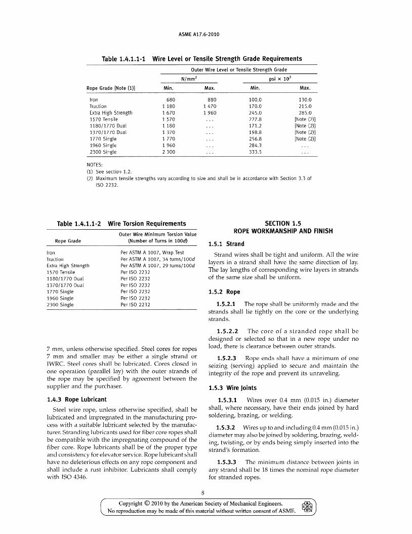
Table 1.4.1.1-1 Wire Level or Tensile Strength Grade Requirements
Outer Wire Level or Tensile Strength Grade
Rope Grade [Note (1)] Min. Max. Min. Max.
Iron 680 880 100.0 130.0 Traction 1 180 1470 170.0 215.0 Extra High Strength 1670 1960 245.0 285.0 1570 Tensile 1 570 227.8 [Note (2)] 1180/1770 Dual 1 180 171.2 [Note (2)] 1370/1770 Dual 1 370 198.8 [Note (2)] 1770 Single 1 770 256.8 [Note (2)] 1960 Single 1 960 284.3 2300 Single 2300 333.5
NOTES: (1) See section 1.2.
(2) Maximum tensile strengths vary according to size and shall be in accordance with Section 3.3 of ISO 2232.
Table 1.4.1.1-2
Rope Grade
Iron Traction Extra High Strength 1570 Tensile 1180/1770 Dual 1370/1770 Dual 1770 Single 1960 Single 2300 Single
Wire Torsion Requirements
Outer Wire Minimum Torsion Value (Number of Turns in lOOd)
Per ASTM A 1007, Wrap Test Per ASTM A 1007, 34 turns/l00d Per ASTM A 1007, 29 turns/l00d Per ISO 2232 Per ISO 2232 Per ISO 2232 Per ISO 2232 Per ISO 2232 Per ISO 2232
7 mm, unless otherwise specified. Steel cores for ropes 7 mm and smaller may be either a single strand or IWRC. Steel cores shall be lubricated. Cores closed in one operation (parallel lay) with the outer strands of the rope may be specified by agreement between the supplier and the purchaser.
1.4.3 Rope Lubricant
Steel wire rope, unless otherwise specified, shall be lubricated and impregnated in the manufacturing process with a suitable lubricant selected by the manufacturer. Stranding lubricants used for fiber core ropes shall be compatible with the impregnating compound of the fiber core. Rope lubricants shall be of the proper type and consistency for elevator service. Rope lubricant shall have no deleterious effects on any rope component and shall include a rust inhibitor. Lubricants shall comply with ISO 4346.
8
SECTION 1.5 ROPE WORKMANSHIP AND FINISH
1.5.1 Strand
Strand wires shall be tight and uniform. All the wire layers in a strand shall have the same direction of lay. The lay lengths of corresponding wire layers in strands of the same size shall be uniform.
1.5.2 Rope
1.5.2.1 The rope shall be uniformly made and the strands shall lie tightly on the core or the underlying strands.
1.5.2.2 The core of a stranded rope shall be designed or selected so that in a new rope under no load, there is clearance between outer strands.
1.5.2.3 Rope ends shall have a minimum of one seizing (serving) applied to secure and maintain the integrity of the rope and prevent its unraveling.
1.5.3 Wire Joints
1.5.3.1 Wires over 0.4 mm (0.015 in.) diameter shall, where necessary, have their ends joined by hard soldering, brazing, or welding.
1.5.3.2 Wires up to and including 0.4 mm (0.015 in.) diameter may also be joined by soldering, brazing, welding, twisting, or by ends being simply inserted into the strand's formation.
1.5.3.3 The minimum distance between joints in any strand shall be 18 times the nominal rope diameter for stranded ropes.
Copyright © 2010 by the American Society of Mechanical Engineers. ~ € S
No reproduction may be made oftbis material without written consent of ASME. m •

ASME A17.6-2010
1.5.4 Preformation
Stranded ropes shall be preformed unless otherwise specified.
1.5.5 Prestretching
When specified, ropes may be prestretched using either a process of static or dynamic loading. Prestretch loads shall not exceed 55% of the minimum breaking force for the rope.
NOTE: An example of static prestretching practice: rope is subjected to three cycles of tensile loading to 40°/.) of the rope minimum breaking force for 5 min each, returning to 5% of the minimum breaking force between cycles. After the last cycle, the tensile force is completely released.
SECTION 1.6 PROPERTIES AND TOLERANCES OF NEWLY
CONSTRUCTED ROPE
1.6.1 Classification
The rope classification shall be specified by the purchaser and shall normally be one of those covered in Mandatory Appendix I,Tables 1-1.1-1,1-1.1-2,1-1.1-3, or 1-1.1-4, although other classifications and constructions may be supplied by agreement between purchaser and manfacturer or supplier.
NOTE: Where only the rope classification is specified by the purchaser, the construction shall be decided by the manufacturer.
1.6.2 Rope Core
Natural fiber cores are supplied unless otherwise specified with core construction selected by the manufacturer. Other cores shall be the subject of agreement between supplier and purchaser.
1.6.3 Rope Grade
Rope grade shall be one of the following although other grades may be supplied by agreement between purchaser and manufacturer or supplier.
(a) Rope Grades for SI units (Table 1-1.1-1, 1-1.1-2, 1-1.1-3, or 1-1.1-4)
(1) 1570 Single: normal hoisting applications (2) 1180/1770 Dual: normal hOisting applications (3) 1370/1770 Dual: normal hoisting applications (4) 1770 Single: high speed/high loading
applications (5) 1960 Single: special hoisting applications (6) 2300 Single: special hoisting applications
(b) Rope Grades for Imperial units (Table 1-1.1-1, 1-1.1-2,1-1.1-3, or 1-1.1-4)
(1) Iron: applications other than hoist rope (2) Traction: normal hoisting applications (3) Extra High Strength: high speed/high loading
applications
9
1.6.4 Wire Finish
Unless otherwise specified, steel wire ropes will be furnished with uncoated wires. For steel wire ropes requested with metallic coated wires, the wires shall be galvanized unless otherwise specified by the purchaser.
1.6.4.1 Final-Galvanized Rope. All outer wires shall be supplied as final-galvanized. Inner, filler, and center wires may be supplied as final-galvanized or drawngalvanized. Minimum weight of coating for galvanized wire shall be as specified in Tables 1.6.4.1-1 and 1.6.4.1-2. An adherence test will be required involving six tightly spaced wraps around a mandrel twice the wire diameter, without peeling or cracking.
1.6.4.1.1 Final Galvanized Rope. Final galvanized rope will be supplied with a minimum nominal breaking force 10% less than that specified in Tables 1-1.1-1, 1-1.1-2, 1-1.1-3, or 1-1.1-4.
1.6.4.1.2 Final-Coated Zn-SAl-MM. Wires of finalcoated Zn-5AI-MM may be substituted for final-galvanized wire at the option of the manufacturer. Minimum weight of coating shall be as specified in Table 1.6.4.1-1.
1.6.4.2 Drawn-Galvanized (Zinc Coated) Rope. All the wires shall be drawn-galvanized (zinc coated), including those of any steel core. Minimum weight of coating shall be as specified in Table 1.6.4.1-2.
1.6.4.2.1 Minimum Breaking Forces. Drawn galvanized rope shall be supplied with minimum breaking forces as listed in Table 1-1.1-1, 1-1.1-2, 1-1.1-3, or 1-1.1-4 unless otherwise agreed to between supplier and purchaser.
1.6.4.2.2 Drawn-Zn-SAl-MM. Wires of drawn-Zn-5AI-MM may be substituted for drawn-galvanized wire at the option of the manufacturer. Minimum weight of coating shall be as specified in Table 1.6.4.1-2.
1.6.5 Direction and Type of Rope Lay
The direction and type of rope lay shall be as specified by the purchaser and shall be one of the following:
(a) Right regular (ordinary) lay (sZ) (b) Left regular (ordinary) lay (zS) (c) Right lang lay (zZ) (d) Left lang lay (sS) Right regular (ordinary) lay will be supplied for 6-
and 8-strand constructions unless otherwise specified by the purchaser.
1.6.6 Dimensions
1.6.6.1 Rope Diameter. The nominal diameter shall be as specified by the purchaser and shall be the dimension by which the rope is designated. See Fig. 1.3.3.1.1-1.
1.6.6.1.1 Tolerance on Rope Diameter. When measured in accordance with 1.7.3.3.1, the actual diameter
Copyright © 2010 by the American Society of Mechanical Engineers. ~ ~ No reproduction may be made of this material without written consent of ASME.

ASME A17.6-2010
Table 1.6.4.1-1 Weight of Coating for Final-Galvanized or Final-Coated Zn-SAl-MM Rope Wire for Newly Constructed Rope
Diameter of Wire
mm
0.51 to 1.19 inclusive Over 1.19 to 1.37 inclusive Over 1.37 to 1.60 inclusive Over 1.60 to 2.01 inclusive Over 2.01 to 2.34 inclusive Over 2.34 to 4.88 inclusive
in.
0.020 to 0.047 inclusive Over 0.047 to 0.054 inclusive Over 0.054 to 0.063 inclusive Over 0.063 to 0.079 inclusive Over 0.079 to 0.092 inclusive Over 0.092 to 0.192 inclusive
Minimum Weight of Coating
0.06 0.20 0.12 0.40 0.15 0.50 0.18 0.60 0.21 0.70 0.24 0.80
Table 1.6.4.1-2 Weight of Coating for Drawn-Galvanized or Drawn-Coated Zn-SAl-MM Rope Wire for Newly Constructed Rope
Diameter of Wire
mm in.
Minimum Weight of Coating
0.15 up to 0.25 0.006 up to 0.010 0.010 0.03 [Note (1)] [Note (1)]
0.25 to 0.43 inclusive 0.010 to 0.017 inclusive 0.015 0.05 Over 0.43 to 0.71 inclusive Over 0.71 to 1.52 inclusive Over 1.52 to 2.29 inclusive Over 2.29 to 3.56 inclusive
Over 0.017 to 0.028 inclusive Over 0.028 to 0.060 inclusive Over 0.060 to 0.090 inclusive Over 0.090 to 0.140 inclusive
0.03 0.10 0.06 0.20 0.09 0.30 0.12 0.40
NOTE: (1) The values shown are in accordance with ISO 2020-1:1997.
Table 1.6.6.1.1-1 Tolerances on Rope Diameter (Stranded Rope) for Newly Constructed Rope With Cores of Fiber or Other Nonmetallic Materials
Nominal Rope Diameter, d Load on mm in. Rope
10 and less % and less None 10% MBF
Greater than 10 Greater than % None 10% MBF
GENERAL NOTE: MBF = minimum breaking force.
shall not vary from the nominal diameter by more than the tolerances specified in Tables 1.6.6.1.1-1 and 1.6.6.1.1-2, in accordance with ISO 4344.
1.6.6.1.2 Permissible Differences in Diameter. The difference between any two of the four measurements taken in accordance with 1.7.3.3.1 and expressed as a percentage of the nominal diameter shall not exceed the values given in Table 1.6.6.1.2-1.
1.6.6.2 Lay Length. The lay length of the finished rope shall not exceed 63
/ 4 times the nominal rope diameter.
10
Diameter Tolerance
Min. Max. Out-of-Round Tolerance
+2% +6% 5% +0% +4% 3% +2% +5% 5% +0% +3% 3%
1.6.7 Mechanical Properties
1.6.7.1 Breaking Force. Values for minimum breaking force for the covered classes of rope are specified in Tables I-1.1-1, I-1.1-2, I-1.1-3, or I-1.1-4.
1.6.7.2 Mass. The approximate rope mass shall be as given in Tables 1-1.1-1, I-1.1-2, I-1.1-3, or I-1.1-4, or as agreed upon by the manufacturer and purchaser.
1.6.7.3 Length. The actual length of rope supplied, expressed in feet or meters, shall be the specified length under no load subject to the following limits of tolerance:
Copyright © 2010 by the American Society of Mechanical Engineers. ~ No reproduction may be made of this material without written consent of ASME. ~

ASME A17.6-2010
Table 1.6.6.1.1-2 Tolerances on Rope Diameter (Stranded Rope) for Newly Constructed Rope With Steel or Steel-Based Composite Cores
Diameter Nominal Rope Diameter, d Load on Tolerance
mm in. Rope Min. Max. Out-of-Round Tolerance
10 and less % and less None +0% +3% 5% 10% MBF -1% +2% 3%
Greater than 10 Greater than % None +0% +3% 5% 10% MBF -1% +2% 3%
GENERAL NOTES: (a) The term "steel-based composite cores" refers to rope constructions with steel plus fiber (natural
or synthetic) cores.
(b) MBF = minimum breaking force.
Table 1.6.6.1.2-1 Permissible Differences in Rope Diameter for Newly Constructed Rope
Nominal Rope Diameter, d
mm
8 and less Greater than 8
in.
%6 and less Greater than ;;'6
Percentage Allowable Difference
5% 4%
(a) up to and including 400 m (1,300 ft): +5.0% of specified length
(b) over 400 m (1,300 ft) and up to 1 000 m (3,280 ft): +3.5% of specified length
(c) over 1000 m (3,280 ft): +2.0 % of specified length
NOTE: Ropes required with smaller length tolerance should be the subject of agreement between the supplier and purchaser.
SECTION 1.7 TESTING AND COMPLIANCE FOR NEWLY
CONSTRUCTED ROPE
1.7.1 General
Steel wire ropes shall be manufactured in accordance with the applicable requirements of this Standard. The manufacturer shall be able to demonstrate compliance with this Standard by complying with either 1.7.2 or 1.7.3.
1.7.2 Compliance
The manufacture shall operate a quality assurance system that includes a sampling program that meets the following requirements:
1.7.2.1 For each new class or size or grade of a given steel wire rope design, each manufacturer shall be able to present evidence from testing of at least one sample from each of three production lengths, showing that the steel wire rope conforms to the requirements as defined in this Part.
11
1.7.2.2 Future production lengths of the same class, size, and grade as in 1.7.2.1 shall be deemed to comply when, at a minimum, a sample from every twentieth production length is subjected to and successfully meets the requirements of the breaking force test.
1. 7.3 Acceptance Tests
1.7.3.1 Test Piece. When required by 1.7.1, one sample shall be tested from each production length.
1.7.3.2 Test Verification. When requested, the manufacturer shall allow the purchaser or his representative the opportunity to witness acceptance tests or to examine test records, to verify compliance with this Part.
NOTE: Test lengths required by the purchaser should be ordered as additional lengths.
1. 7 .3.3 Rope
1.7.3.3.1 Diameter. Measurements for diameter shall be taken on a straight portion of the rope at two positions spaced at approximately 1 m (or 3 ft) apart and at each position two diameters at right angles shall be measured. These measurements shall be performed both with and without tension. The respective average of each set of four measurements shall be within the tolerances given in Tables 1.6.6.1.1-1 and 1.6.6.1.1-2. The permissible difference between any two measurements at 90 deg at the same point expressed as a percentage shall be within the out-of-round tolerances given in Tables 1.6.6.1.1-1 and 1.6.6.1.1-2.
1.7.3.3.2 Breaking Force. When measured in accordance with the method specified in ASTM A 931 or ISO 3108, the actual (measured) breaking force obtained shall be equal to or greater than the minimum breaking force specified in the appropriate part of this Part. When the minimum breaking force is not reached, two additional tests are required, both of which have to achieve the minimum breaking force.
1.7.3.4 Rope Wires
Copyright © 2010 by the American Society of Mechanical Engineers. ~ ~ No reproduction may be made of this material without written consent of ASME.

ASME A17.6-2010
1.7.3.4.1 Tests. Tests on wires shall be carried out in respect of diameter, tensile strength, and torsions, and, where applicable, metallic coating in accordance with the methods in ASTM A 1007 or ISO 2232. The manufacturer shall have the option to test wires either before or after fabrication of the rope.
NOTE: After fabrication wire testing does not apply to compacted strand ropes.
1.7.3.4.2 Sampling. All main wires from the equivalent of one complete strand, including steel rope core if applicable, shall be tested. For the purposes of evaluating the test results, the rope manufacturer shall specify the nominal diameters and tensile grades of the wires.
(a) The sample selected shall be of sufficient length to allow for retest.
(b) The wires shall be selected at random. (c) Filler wires and other non-load bearing wires shall
be excluded from this test.
1.7.3.4.3 levels of Acceptance (a) Wire Before Fabrication. Wire samples tested before
fabrication shall meet the requirements for the size and grade (level) specified by the supplier and as found in the appropriate wire standard.
(b) Wire After Fabrication. For each requirement in (1), (2) and (3) below, a maximum of 5% of wires tested is permitted to lie outside the values specified, rounded to the nearest whole number of wires. Where the same wire fails in more than one test, this is counted as one failure.
(1) Diameter. When tested in accordance with the wire standard referred to in the appropriate part of this standard; the 5% of the wires may exceed, by up to 50%, the specified tolerance for the nominal diameter.
(2) Tensile Strength. When tested in accordance with ASTM A 1007, the measured values shall be within the tolerance specified in the wire standard referred to in the appropriate part of this standard with an additional tolerance of 50 N / mm2 (7,000 psi) below the minimum value.
(3) Torsion. When tested in accordance with ASTM A 1007, the measured values of wires of 0.5 mm (0.020 in.) diameter and greater shall be at least 85% of the values specified in the wire standard referred to in the appropriate part of this standard, rounded down to the next whole number. The measured value of wire diameters less than 0.5 mm (0.020 in.) for 1.7.3.4.3(b)(2) and 1.7.3.4.3(b )(3) shall be at or above the minimum values specified in the appropriate wire standard.
1.7.4 Special Purpose
Manufacturers complying with all requirements of 1.7.2 and 1.7.3 may use calculated breaking force to verify compliance with requirements for
12
(a) individual production length not included in sample testing; or
(b) individual production lengths of lesser grade ropes of the same size and same design that have not been included in the sample testing.
NOTE: Examples of acceptable quality assurance systems are API Ql, ANSI/ ASQC Q9001, and ISO 9001.
SECTION 1.8 ORDERING INFORMATION
1.8.1 Typical Information
Typical information used to order steel wire rope shall include items 1 through 7 in Table 1.8.1-1 and may include but is not limited to additional items noted.
1.8.2 Certification of Conformance and Test
A certificate of conformance and test shall confirm compliance with Part 1. It shall contain all of the information listed in 1.8.2.1. The items in 1.8.2.2 shall be completed as agreed between the supplier and the purchaser.
The additional information listed in 1.8.2.2 and 1.8.2.3 can be supplied under agreement between purchaser and supplier.
1.8.2.1 Confirmation Data
- certificate number
- purchaser name and address
- purchaser order number
- rope supplier name and address
- supplier order number
- number traceable to manufacturer's production length
- nominallength(s) of rope
- rope designation, (nominal diameter, construction and core, lay and grade)
- minimum breaking force in kilonewtons or pounds
1.8.2.2 Tests on Wires and Rope
- quality system registration number of the rope manufacturer, if applicable
- approximate mass in kg/m (lb/ft)
- wire standard used
- number of wires tested
- nominal dimensions of wire
- measured dimensions of wire
- breaking force of wire
- tensile strength of wire
Copyright © 2010 by the American Society of Mechanical Engineers. ~ No reproduction may be made of this material without written consent of ASME. ~

ASME A17.6-2010
Table 1.8.1-1 Ordering Information
Item
1) Length 2) Size (diameter)
3) Rope classification or construction Of known) 4) Preformed or nonpreformed
5) Lay direction and type 6) Rope grade 7) Wire finish (bright or galvanized and type) 8) Core type
9) Applicable standard 10) Special requirements
a) Termination of rope ends b) Special length tolerance
c) Type of certificate d) Special packaging and identification
e) Lubrication, other than as noted in 1.4.3 f) Prestretching
- number of torsions completed (and test length)
- mass of zinc (or zinc alloy)
- actual (measured) diameter of rope
- actual (measured) breaking force of rope
1.8.2.3 Additional Information and Certification
- space for additional information
- space for certification with provision for certifying the foregoing, name and position held, signature, and date
SECTION 1.9 PACKAGING AND IDENTIFICATION
1.9.1 Packaging
Unless otherwise specified by the purchaser, ropes shall be supplied in coils or on reels at the discretion of the manufacturer-
1.9.2 Identification
Each package of rope shall be legibly identified with at least the following information:
- rope supplier and address
- rope length and description
- number traceable to manufacturer's production length
NOTES:
SECTION 1.10 REPLACEMENT CRITERIA
(1) Replacement criteria for steel wire rope are based on the worst conditions of diameter and wire breaks. Crown wires are subject to both wear that reduces the diameter of the rope and
13
Example 1, SI
100 m
10 mm 6 x 25 Nonpreformed sZ 1370/1770 Dual Drawn-galvanized Synthetic ASME A17.6, Part 1
Example 2, Imperial
500 ft % in. 8 x 195 Preformed Right regular Traction
Uncoated Natural fiber ASME A17.6, Part 1
the breaks that occur in the wear area. Breaks that are visible and occur outside of the crown wear area with the crown wire intact are called valley breaks.
(2) Where ropes are subjected to reverse bends or where ropes are installed on nonmetallic sheaves or sheaves with nonmetallic liners or inserts, extra attention must be given to the rope due to possible acceleration of valley breaks.
1.10.1 Traction Drive Machines
1.10.1.1 Replacement requirements for steel wire suspension ropes for traction elevators shall be as follows (see Nonmandatory Appendix A):
(a) The steel wire rope(s) shall be replaced if the rope is permanently kinked, bent, or deformed in any way (see 1.10.5).
(b) For rope diameters equal to or greater than 8 mm (0.315 in.), the ropes shall be replaced in accordance with 1.10.1.2(a) through 1.10.1.2(g) and 1.10.3.
(c) For rope diameters less than 8 mm (0.315 in.), the ropes shall be replaced in accordance with 1.10.1.2(a) through (g), 1.10.1.2.1 and 1.10.1.2.2, and 1.10.3. In addition, other replacement criteria based on the application shall be permitted to be applied. The replacement criteria shall be documented in the Maintenance Control Program (see ASME A17.1/CSA B44, requirement 8.6.1.4.1).
1.10.1.2 Criteria for replacement include at least one of the following:
(a) if the broken crown wires are equally distributed among the strands, when the number of broken wires per rope lay in the worst section of rope exceeds the values shown in the "Normal Wear Conditions," first column of Table 1.10.1.2-1
(b) if the distribution of breaks is unequal and broken crown wires predominate in one or two strands, when the number of broken wires per rope lay in the worst section of rope or the minimum diameter exceeds the
Copyright © 2010 by the American Society of Mechanical Engineers. ~ ~ No reproduction may be made of this material without written consent of ASME.

ASME A17.6-2010
Table 1.10.1.2-1 Wire Breaks: Crown Wire Breaks Per Lay Length
6-Strand Rope Applications
Normal Unfavorable Ropes Wear Wear Showing
Conditions Conditions Rouge
Distributed breaks 24 12 12
(max.) Unequal breaks 8 4 4
(max.) 4 Side-by-Side 12 6 6
Breaks
8- and 9-Strand Rope Applications
Normal Unfavorable Ropes Wear Wear Showing
Conditions Conditions Rouge
Distributed 32 16 16 breaks (max.)
Unequal breaks 10 (max.)
4 Side-by-Side 16 8 8 Breaks
GENERAL NOTES: (a) Where ropes are subjected to reverse bends or where ropes
are installed on nonmetallic coated, plastic, fiber-reinforced plastic sheaves or sheaves with nonmetallic liners or inserts, extra attention must be given to any steel wire rope (6, 8, or 9 strand) due to possible acceleration of valley breaks.
(b) This table does not apply to Winding Drum Machines. See 1.10.2 for replacement criteria.
(c) No more than one valley break per lay length and no valley breaks allowed if visible rouge.
(d) For ropes less than 8 mm, also see 1.10.1.2.2 for additional replacement requirements.
values shown in the "Normal Wear Conditions," first column of Table 1.10.1.2-1
(c) if four wires, side by side, are broken across the crown of any strand, when the number of broken wires per rope lay in the worst section of rope exceeds the values shown in the "Normal Wear Conditions," first column of Table 1.10.1.2-1
(d) if an unfavorable condition exists, such as but not limited to corrosion due to external conditions, excessive wear of individual wires in the strands, unequal tension, poor sheave grooves; the criteria for broken crown wires shall be the values indicated in the "Unfavorable Wear Conditions," second column of Table 1.10.1.2-1 for any of the conditions described above
(e) if red dust or rouge exists, the criteria for broken wires shall be the values indicated in the "Rope Showing Rouge," third column of Table 1.10.1.2-1 for any of the conditions described above
(f) if there is more than one valley break per rope lay (g) if there are any valley breaks at any location where
rouge exists
14
1.10.1.2.1 The elevator manufacturer using information from the rope manufacturer and considering the application, shall establish the design life limit to ensure that the residual strength of wire ropes less than 8 mm (0.315 in.) diameter is not less than 60% of the minimum breaking force at the time of replacement.
1.10.1.2.2 Steel wire ropes of less than 8 mm (0.315 in.) in diameter shall be replaced when there is evidence of rouge.
1.10.2 Winding Drum Machines
Suspension ropes shall be replaced on winding drum machines if
(a) the broken crown wires are equally distributed among the strands, when the number of broken wires per rope lay in the worst section of rope exceeds 12;
(b) the broken crown wires predominate in one or two strands, when the number of broken wires per rope lay in the worst section of rope exceeds 6;
(c) there is more than one valley break per rope lay; or (d) there are any valley breaks at any location where
rouge exists
1.10.3 AU Elevator Types
The suspension, compensation, and governor ropes shall be replaced when their actual diameter is reduced below the value shown in Table 1.10.3-1. For nominal diameters not listed in Table 1.10.3-1, the minimum diameter reduction shall be calculated using the criteria outlined in General Notes (a) and (b) of Table 1.10.3-1. Normal wear diameters, unfavorable wear, and rouge conditions as listed in the table shall apply. Compensation and governor ropes shall also conform to 1.10.1.1(a) and 1.10.1.2(a) through 1.10.1.2(g).
Measurement for diameter shall be taken on a straight portion of rope at the worst location. Two measurements at the same position at right angles shall be taken. The ropes shall be replaced if both of these measurements are below the replacement value. However, if only one of the measurements is below the replacement value, then the criteria for wire breaks under "Unfavorable Wear Conditions" shall apply. See Table 1.10.1.2-1.
1.10.4 Replacement of Ropes
Replacement of all ropes, except governor ropes (see ASME A17.1/CSA B44, requirement 8.6.3.4), shall conform to the requirements of 1.10.4.1 through 1.10.4.6.
1.10.4.1 Replacement ropes shall be as specified by the original elevator manufacturer or be at least equivalent in strength, weight, and design.
1.10.4.2 Ropes that have previously been installed and used on another installation shall not be reused.
1.10.4.3 When replacing suspension, compensating, and car or drum counterweight ropes, all ropes in a set shall be replaced, except as permitted by 1.10.5.
Copyright © 2010 by the American Society of Mechanical Engineers. No reproduction may be made of this material without written consent of ASME.
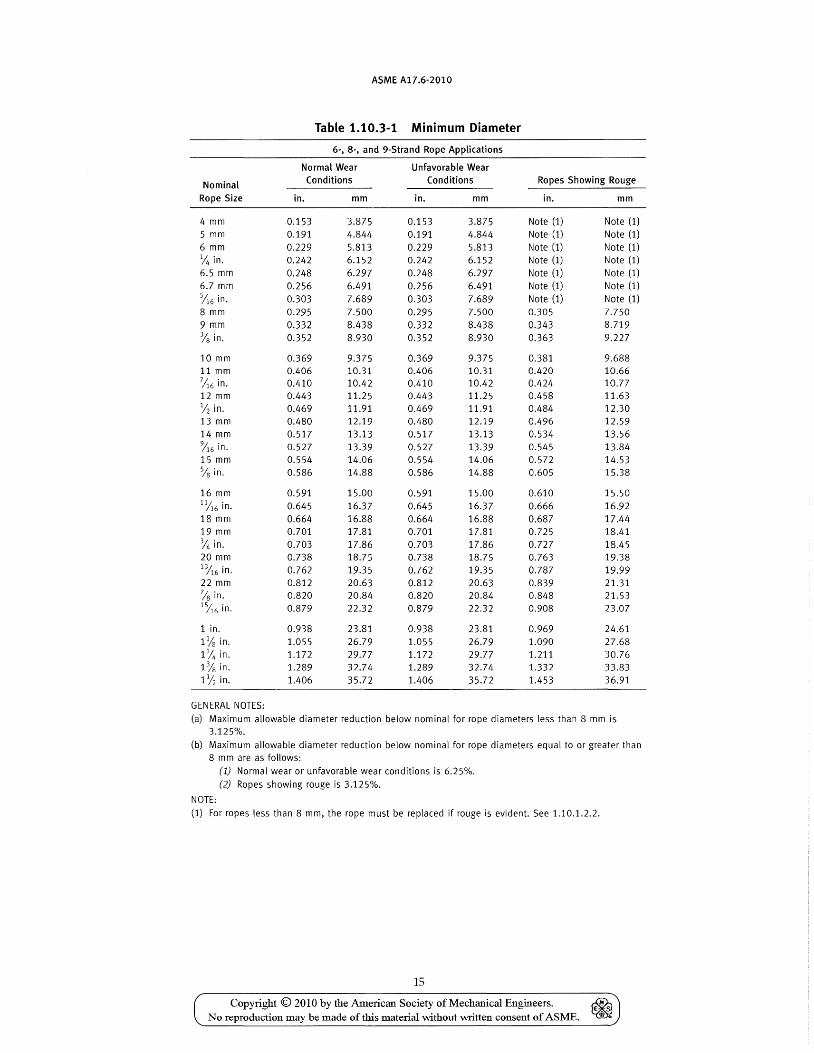
ASME A17.6-2010
Table 1.10.3-1 Minimum Diameter
6-, 8-, and 9-Strand Rope Applications
Normal Wear Unfavorable Wear
Nominal Conditions Conditions Ropes Showing Rouge
Rope Size in. mm in. mm in. mm
4 mm 0.153 3.875 0.153 3.875 Note (1) Note (1) 5 mm 0.191 4.844 0.191 4.844 Note (1) Note (1) 6 mm 0.229 5.813 0.229 5.813 Note (1) Note (1) % in. 0.242 6.152 0.242 6.152 Note (1) Note (1) 6.5 mm 0.248 6.297 0.248 6.297 Note (1) Note (1) 6.7 mm 0.256 6.491 0.256 6.491 Note (1) Note (1)
%6 in. 0.303 7.689 0.303 7.689 Note (1) Note (1) 8 mm 0.295 7.500 0.295 7.500 0.305 7.750 9 mm 0.332 8.438 0.332 8.438 0.343 8.719 % in. 0.352 8.930 0.352 8.930 0.363 9.227
10 mm 0.369 9.375 0.369 9.375 0.381 9.688 11 mm 0.406 10.31 0.406 10.31 0.420 10.66 7A6 in. 0.410 10.42 0.410 10.42 0.424 10.77 12 mm 0.443 11.25 0.443 11.25 0.458 11.63 % in. 0.469 11.91 0.469 11.91 0.484 12.30 13 mm 0.480 12.19 0.480 12.19 0.496 12.59 14 mm 0.517 13.13 0.517 13.13 0.534 13.56 %6 in. 0.527 13.39 0.527 13.39 0.545 13.84 15 mm 0.554 14.06 0.554 14.06 0.572 14.53 % in. 0.586 14.88 0.586 14.88 0.605 15.38
16 mm 0.591 15.00 0.591 15.00 0.610 15.50 11/16 in. 0.645 16.37 0.645 16.37 0.666 16.92 18 mm 0.664 16.88 0.664 16.88 0.687 17.44 19 mm 0.701 17.81 0.701 17.81 0.725 18.41 % in. 0.703 17.86 0.703 17.86 0.727 18.45 20 mm 0.738 18.75 0.738 18.75 0.763 19.38 13/16 in. 0.762 19.35 0.762 19.35 0.787 19.99 22 mm 0.812 20.63 0.812 20.63 0.839 21.31 7/S in. 0.820 20.84 0.820 20.84 0.848 21.53 1J16 in. 0.879 22.32 0.879 22.32 0.908 23.07
1 in. 0.938 23.81 0.938 23.81 0.969 24.61 1% in. 1.055 26.79 1.055 26.79 1.090 27.68 1% in. 1.172 29.77 1.172 29.77 1.211 30.76 1% in. 1.289 32.74 1.289 32.74 1.332 33.83 1% in. 1.406 35.72 1.406 35.72 1.453 36.91
GENERAL NOTES: (a) Maximum allowable diameter reduction below nominal for rope diameters less than 8 mm is
3.125%. (b) Maximum allowable diameter reduction below nominal for rope diameters equal to or greater than
8 mm are as follows: (1) Normal wear or unfavorable wear conditions is 6.25%. (2) Ropes showing rouge is 3.125%.
NOTE: (1) For ropes less than 8 mm, the rope must be replaced if rouge is evident. See 1.10.1.2.2.
15
Copyright © 2010 by the American Society of Mechanical Engineers. No reproduction may be made of this material without written consent of ASME.

ASME A17.6·2010
1.10.4.4 The ropes in the set shall be new, all from the same manufacturer and of the same material, grade, construction, and diameter.
1.10.4.5 Data tags conforming to ASME AI7.1/ CSA B44, requirement 2.20.2.2 shall be applied.
1.10.4.6 Suspension, car, and drum counterweight rope fastenings shall conform to ASME AI7.1/CSA B44, requirement 2.20.9.
1.10.5 Replacement of a Single Suspension Rope If one rope of a set is worn or damaged and requires
replacement, the entire set of ropes shall be replaced; except, where one rope has been damaged during installation or acceptance testing prior to being subjected to elevator service, it shall be permissible to replace a single damaged rope with a new rope provided that the requirements of 1.10.4.4 and 1.10.5.1 through 1.10.5.1.6 are met. NOTE: Damage includes but is not limited to kinked ropes.
1.10.5.1 The steel wire rope data for the replace-ment rope must correspond to the steel wire rope data specified in ASMEA17.1/CSA B44, requirement 2.20.2.2.
16
1.10.5.2 The replacement rope shall be provided with a data tag conforming to AS ME AI7.1/CSA B44, requirement 2.20.2.2.
1.10.5.3 The suspension ropes, including the damaged rope, shall not have been shortened since their original installation.
1.10.5.4 The diameter of any of the remaining ropes shall not be less than the nominal diameter minus 0.4 mm (0.015 in.).
1.10.5.5 The tension of the new replacement rope shall be checked and adjusted as necessary at semimonthly intervals over a period of not less than 2 mo after installation. If proper equalization of the rope tension cannot be maintained after 6 mo, the entire set of suspension ropes shall be replaced.
1.10.5.6 The replacement rope shall be provided with the same type of suspension rope fastening used with the other ropes.
Copyright © 2010 by the American Society of Mechanical Engineers. ~ No reproduction may be made of this material without written consent of ASME. ~

ASME A17.6-2010
MANDATORY APPENDIX I TABLES
SECTION 1·1.1 BREAKING FORCE AND DIAMETER TOLERANCE
Tables I-1.1-1, I-1.1-2, I-1.1-3, and I-1.1-4 show the breaking forces and diameter tolerances of the more common classes, sizes, and grades of steel wire rope under Part 1. The following requirements apply:
(a) Minimum breaking forces listed apply to uncoated or drawn-galvanized ropes.
(b) Minimum breaking forces for final-galvanized ropes are 10% lower than the values listed.
(c) Minimum breaking forces for compacted strand ropes are 10% higher than values listed.
17
Copyright © 2010 by the American Society of Mechanical Engineers. ~ No reproduction may be made of this material without written consent of ASME. ~

~ 0;
'@ Q o '"0 g-~ &.i § .-+
S @ ~ ~ 0"' ...... ('t> 0
s~ ~S" ('t> ('t>
~~ ~ 3. s a a § I ...... ('t> VJ 00 ::1·0 til a
t~' S'o o ~ a~
~. 8-~ ~. (") e:.. § t'l1 V> t:l ('t> (Jq
a s· o ~ .....,~
> ~ r.n
~ ~ ~
Diameter
Approximate Mass
[Note (1)]
Table 1-1.1-1 Classification 6 x 19 FC, Round Strand, Fiber Core or Polymer Core
Rope Grade, Minimum Breaking Force (MBF) [Note (2)]
1180/ TS 1770 1370/ Diameter, Relaxed
Iron [Note (3] EHS [Note (4)] 1770 1570 1770 Min. Max.
in. mm Ib/ft kg/m Ibf x 100 kN [Note (5)] in. mm in. mm
% %6
%
116
Y2
':116
%
1~6
%
13/16
'is 1%6
1
118 1% 1% 1%
6 6.4 0.10 7.9 0.16 8
9 9.5 0.23
10 11 11.1 0.31 12 12.7 0.40 13 14 14.3 0.51 15 15.9 0.63 16 17.5 0.76 18 19 19.1 0.90 20 20.6 1.06 22 22.2 1.23 23.8 1.41 25.4 1.60 28.6 2.03 31.8 2.50 34.9 3.03 38.1 3.60
0.130
0.231 0.291
0.361 0.437
0.517
0.610 0.704
0.808
0.924
1.160 1.300
1.440
1.750
2.2 3.6 5.2 3.2 5.6 8.1
5.0 8.2 11.6
6.4 11.0 15.7
8.4 14.5 20.4
10.6 18.5 25.7
12.8 23.0 31.6
15.5 27.0 38.2
18.2 32.0 45.2
21.5 37.0 52.9
24.8 42.0 61.2 28.5 48.0 70.0 32.0 54.0 79.5 40.5 67.4 49.8 82.0 60.0 98.0 71.2 115.0
16.3
28.9 36.6
45.2 54.7
65.1
76.4 88.6
102.0
116.0
146.0 163.0
181.0
219.0
17.8 18.7
31.7 33.2 40.1 42.0
49.5 51.8 59.9 62.7
71.3 74.6
83.7 87.6 97.0 102.0
111.0 117.0
127.0 133.0
160.0 168.0 179.0 187.0
198.0 207.0
240.0 251.0
21.0 0.241 0.255 0.319
37.4 0.321 47.3 0.361
0.383 58.4 0.402 70.7 0.442
0.446 84.1 0.482
0.510 98.7 0.522
114.0 0.562 0.574
131.0 0.602 0.638
150.0 0.643 0.701
189.0 0.723 211.0 0.763
0.765 234.0 0.803
0.829 283.0 0.883
0.893 0.956 1.020 1.148 1.275 1.403 1.530
6.12 0.250 6.48 0.265 8.10 0.331 8.16 0.334 9.18 0.376 9.72 0.398
10.20 0.417 11.22 0.455 11.33 0.459 12.24 0.496 12.95 0.525 13.26 0.537 14.28 0.579 14.57 0.591 15.30 0.620 16.19 0.656 16.32 0.661 17.81 0.722 18.36 0.744 19.38 0.785 19.43 0.788 20.40 0.827 21.05 0.853 22.44 0.909 22.67 0.919 24.29 0.984 25.91 1.050 29.15 1.181 32.39 1.313 35.62 1.444 38.86 1.575
6.36 6.73 8.41 8.48 9.54
10.10 10.60 11.55 11.67 12.60 13.34 13.65 14.70 15.00 15.75 16.67 16.80 18.34 18.90 19.95 20.00 21.00 21.67 23.10 23.34 25.00 26.67 30.00 33.34 36.67 40.01
Diameter, 10% of MBF
Min.
in. mm
0.236 6.00 0.250 6.35 0.313 7.94 0.315 8.00 0.354 9.00 0.375 9.53 0.394 10.00 0.433 11.00 0.438 11.11 0.472 12.00 0.500 12.70 0.512 13.00 0.551 14.00 0.563 14.29 0.591 15.00 0.625 15.88 0.630 16.00 0.688 17.46 0.709 18.00 0.748 19.00 0.750 19.05 0.787 20.00 0.813 20.64 0.866 22.00 0.875 22.23 0.938 23.81 1.000 25.40 1.125 28.58 1.250 31.75 1.375 34.93 1.500 38.10
Max.
in.
0.246 0.260 0.325 0.328 0.369 0.390 0.409 0.446 0.451 0.487 0.515 0.527 0.568 0.579 0.608 0.644 0.649 0.708 0.730 0.770 0.773 0.811 0.837 0.892 0.901 0.966 1.030 1.159 1.288 1.416 1.545
mm
6.24 6.60 8.26 8.32 9.36 9.91
10.40 11.33 11.45 12.36 13.08 13.39 14.42 14.72 15.45 16.35 16.48 17.99 18.54 19.57 19.62 20.60 21.26 22.66 22.89 24.53 26.16 29.43 32.70 35.97 39.24
» Vl :s: I"T'I
» .... ""-J
0-N o .... o

~ >-! .g n 8>8 §"'~ (') ..... ;::to C§. § .... S @ ~ ~ 0"'<P 0
S r:T p)'<
~g-
~~ [. g. s (') ~ § <P I/J ::l.o p) (') I ; (0' ~ ;:;..~ Soo o I-+)
a~
~. g. ~ S.
(') (') tll
o -~ tr:1 rFJ I:l <P(Jq
a s· o <P >-<;<P
>0 [f1
~ ~ ~
Table 1-1.1-1 Classification 6 x 19 FC, Round Strand, Fiber Core or Polymer Core (Cont'd)
GENERAL NOTES:
(a) Precise values of Modulus of Elasticity can be provided by the rope supplier. (b) The typical value of Modulus of Elasticity for Classification 6 x 19 fiber core is 10.8 x 10⁶ psi.
(c) To convert GPa to psi, multiply GPa by 145.04 x 10³•
(d) MBF values are based on ISO 4344 including Annex B and Annex C.
NOTES: (1) Masses may be different for compacted or galvanized ropes.
(2) Minimum breaking forces for final-galvanized ropes are 10% lower than the values listed. See 1-1.1.
(3) TS is Traction Steel Rope.
(4) Metric rope numbering is based on the N/mm 2 tensile strengths. Dual rope numbering refers to the outer wire and inner wire strengths. (5) To convert to lbf multiply kilonewton (kN) by 224.8.
» Vl :5: IT1
» ...... --.,J
'" ~ o ...... o

z o >-! .g n >-! 0 o "0 g.~
a.% g ..... s @ ~ N
'< 0 cr(1) 0
S cr ~ '< ftg ~~ e:(1) 'Fl ::1. S 0
~ § IN (1) r:/l 0 ::1. 0 ~ 0
i$ I:TO o ,..., a ~ ~. g. g ~. o e:.. g trj 'Fl ~ (1) (JQ
a s· o (1) ,...,(1)
> ?i r:/l
~ ~ ~
Diameter
in.
% '116
%
7;16
V2
%6
%
11;;.6
%
1116
7/8
1%6 1
11'8 1% 1% 11';;
mm
6 6.4 7.9 8
9 9.5
10 11 11.1 12 12.7 13 14 14.3 15 15.9 16 17.5 18 19 19.1 20 20.6 22 22.2 23.8 25.4 28.6 31.8 34.9 38.1
Approximate Mass
[Note (1)]
Ib/ft
0.09 0.14
0.20
0.28
0.36
0.46
0.57
0.69
0.82
0.96
1.11 1.27 1.45 1.84 2.27 2.74 3.26
kg/m
0.122
0.222 0.275
0.347 0.420
0.490
0.586 0.666
0.765
0.888
1.100 1.250
1.360
1.680
Table 1-1.1-2 Classification 8 x 19 FC, Round Strand, Fiber Core or Polymer Core
Iron
1.8 2.9
4.2
5.6
7.2
9.2
11.2
13.4
16.0
18.6
21.4 24.6 28.0 35.2 43.3 52.2 61.9
Rope Grade, Minimum Breaking Force (MBF) [Note (2)]
TS [Note (3]
Ibf x 100
EHS
3.6 4.5 5.6 6.9
8.2 9.9
11.0 13.5
14.5 17.5
18.5 22.1
23.0 27.2
27.0 32.8
32.0 38.9
37.0 46.0
42.0 52.6 48.0 60.0 54.0 68.4 67.4 86.3 82.0 106.2 98.0 128.2
115.4 152.0
1180/ 1770 1370/
[Note (4)] 1770 1570
14.5
25.7 32.5
40.1 48.6
57.8
67.8 78.7
90.3
103.0
130.0 145.0
161.0
194.0
kN [Note (5)]
15.8 16.6
28.1 29.4 35.6 37.3
44.0 46.0 53.2 55.7
63.3 66.2
74.3 77.7 86.1 90.2
98.9 104.0
113.0 118.0
142.0 149.0 159.0 166.0
176.0 184.0
213.0 223.0
1770
in.
18.7 0.241 0.255 0.319
33.2 0.321 42.0 0.361
0.383 51.9 0.402 62.8 0.442
0.446 74.7 0.482
0.510 87.6 0.522
102.0 0.562 0.574
117.0 0.602 0.638
133.0 0.643 0.701
168.0 0.723 187.0 0.763
0.765 207.0 0.803
0.829 251.0 0.883
0.893 0.956 1.020 1.148 1.275 1.403 1.530
Diameter, Relaxed
Min. Max.
mm in.
6.12 0.250 6.48 0.265 8.10 0.331 8.16 0.334 9.18 0.376 9.72 0.398
10.20 0.417 11.22 0.455 11.33 0.459 12.24 0.496 12.95 0.525 13.26 0.537 14.28 0.579 14.57 0.591 15.30 0.620 16.19 0.656 16.32 0.661 17.81 0.722 18.36 0.744 19.38 0.785 19.43 0.788 20.40 0.827 21.05 0.853 22.44 0.909 22.67 0.919 24.29 0.984 25.91 1.050 29.15 1.181 32.39 1.313 35.62 1.444 38.86 1.575
mm
6.36 6.73 8.41 8.48 9.54
10.10 10.60 11.55 11.67 12.60 13.34 13.65 14.70 15.00 15.75 16.67 16.80 18.34 18.90 19.95 20.00 21.00 21.67 23.10 23.34 25.00 26.67 30.00 33.34 36.67 40.01
in.
0.236 0.250 0.313 0.315 0.354 0.375 0.394 0.433 0.438 0.472 0.500 0.512 0.551 0.563 0.591 0.625 0.630 0.688 0.709 0.748 0.750 0.787 0.813 0.866 0.875 0.938 1.000 1.125 1.250 1.375 1.500
Diameter, 10% of MBF
Min.
mm
6.00 6.35 7.94 8.00 9.00 9.53
10.00 11.00 11.11 12.00 12.70 13.00 14.00 14.29 15.00 15.88 16.00 17.46 18.00 19.00 19.05 20.00 20.64 22.00 22.23 23.81 25.40 28.58 31.75 34.93 38.10
Max.
in.
0.246 0.260 0.325 0.328 0.369 0.390 0.409 0.446 0.451 0.487 0.515 0.527 0.568 0.579 0.608 0.644 0.649 0.708 0.730 0.770 0.773 0.811 0.837 0.892 0.901 0.966 1.030 1.159 1.288 1.416 1.545
mm
6.24 6.60 8.26 8.32 9.36 9.91
10.40 11.33 11.45 12.36 13.08 13.39 14.42 14.72 15.45 16.35 16.48 17.99 18.54 19.57 19.62 20.60 21.26 22.66 22.89 24.53 26.16 29.43 32.70 35.97 39.24
~ f.n s: ,."
~ ..... "'.J
0-N o ..... o

~ .g n a.§ §"~ &. i 8 -s @ ~ l:5 cr- ...... (!l 00
s~ ~g. (!l (1)
~~ [. g. s (") a. § (!l \/J ::l.o ~ (")
t~· goo o >-+)
a ~ §. 8-~ ~. (") e. 8 m [/) I:l (!lac;
a s· o (1) >-+)(1)
>~ r/'1
~ ~ ~
tv .......
Table 1-1.1-2 Classification 8 x 19 FC, Round Strand, Fiber Core or Polymer Core (Cont'd)
GENERAL NOTES:
(a) Precise values of Modulus of Elasticity can be provided by the rope supplier. (b) The typical value of Modulus of Elasticity for Classification 8 x 19 fiber core is 8.1 x 10⁶ psi.
(c) To convert GPa to psi, multiply GPa by 145.04 x 10³.
(d) MBF values are based on ISO 4344 including Annex B and Annex C.
NOTES:
(1) Masses may be different for compacted or galvanized ropes.
(2) Minimum breaking forces for final-galvanized ropes are 10% lower than the values listed. See 1-1.1. (3) TS is Traction Steel Rope.
(4) Metric rope numbering is based on the N/mm 2 tensile strengths. Dual rope numbering refers to the outer wire and inner wire strengths. (5) To convert to lbf multiply kilonewton (kN) by 224.8.
» Vl ~ IT1
» ..... '"'.J ~ N o ..... o

~ >-j
~ Q o "1j 0..« ~ ::!. &.f§. o ..... I:l S @ t>:l N
'< 0 cr"(l) 0
S cr" t>:l « fS-g-~~ ~ g. S () a ~ I N (l) r./J N ::!.O t>:l ()
i$ sto o i-+)
Ea ~ ~. g. g ~. () t>:l o -I:l tI1 VJ I:l (l) (JQ
a s· o (I) ....,(1) >- ?l r./l
~ ~ w
Diameter
in.
%
~6
%
)16
~
%6
%
1%6
% nA6
'is 15/
16
1
1% 1% 1% 111S
mm
6 6.4 6.5 7.9 8 9 9.5
10 11 11.1 12 12.7 13 14 14.3 15 15.9 16 17.5 18 19 19.1 20 20.6 22 22.2 23.8 25.4 28.6 31.8 34.9 38.1
Approximate Mass
[Note (1)]
lb/ft
0.111
0.172
0.247
0.337
0.441
0.560
0.692
0.838
0.998
1.160
1.350 1.550 1.760 2.240 2.770 3.330 3.970
kg/m
0.147
0.172
0.260 0.330
0.407 0.492
0.586
0.688 0.798
0.916
1.040
1.320 1.470
1.630
1.970
Table 1-1.1-3 Classification 8 x 19, Round Strand, Steel Core
Rope Grade, Minimum Breaking Force (MBF) [Note (2)]
TS [Note (3]
lbf x 100
EHS
5.1 5.7
7.9 8.9
11.4 12.9
15.5 17.5
20.3 22.8
25.6 28.9
31.7 35.7
38.3 43.2
45.6 51.4
53.5 60.3
62.1 70.0 71.2 80.3 81.1 91.4
103.0 116.0 127.0 143.0 153.0 173.0 182.0 206.0
1370/ 1770 1570/
[Note (4)] 1770 1570 1770
20.1
35.8 45.3
55.9 67.6
80.5
94.5 110.0
126.0
143.0
181.0 202.0
224.0
kN [Note (5)]
21.4 20.1 22.7
38.0 35.8 40.3 48.2 45.3 51.0
59.5 55.9 63.0 71.9 67.6 76.2
85.6 80.5 90.7
100.0 94.5 106.0 117.0 110.0 124.0
134.0 126.0 142.0
152.0 143.0 161.0
193.0 181.0 204.0 215.0 202.0 227.0
238.0 224.0 252.0
1960
29.5
Diameter, Relaxed
Min.
in.
0.236 0.250 0.256 0.313 0.315 0.354 0.375 0.394 0.433 0.438 0.472 0.500 0.512 0.551 0.563 0.591 0.625 0.630 0.688 0.709 0.748 0.750 0.787 0.813 0.866 0.875 0.938 1.000 1.125 1.250 1.375 1.500
mm
6.00 6.35 6.50 7.94 8.00 9.00 9.53
10.00 11.00 11.11 12.00 12.70 13.00 14.00 14.29 15.00 15.88 16.00 17.46 18.00 19.00 19.05 20.00 20.64 22.00 22.23 23.81 25.40 28.58 31.75 34.93 38.10
Max.
in.
0.243 0.258 0.264 0.322 0.324 0.365 0.386 0.406 0.446 0.451 0.487 0.515 0.527 0.568 0.579 0.608 0.644 0.649 0.708 0.730 0.770 0.773 0.811 0.837 0.892 0.901 0.966 1.030 1.159 1.288 1.416 1.545
mm
6.18 6.54 6.70 8.18 8.24 9.27 9.81
10.30 11.33 11.45 12.36 13.08 13.39 14.42 14.72 15.45 16.35 16.48 17.99 18.54 19.57 19.62 20.60 21.26 22.66 22.89 24.53 26.16 29.43 32.70 35.97 39.24
in.
0.234 0.248 0.253 0.309 0.312 0.351 0.371 0.390 0.429 0.433 0.468 0.495 0.507 0.546 0.557 0.585 0.619 0.624 0.681 0.702 0.741 0.743 0.780 0.804 0.857 0.866 0.928 0.990 1.114 1.238 1.361 1.485
Diameter, 10% of MBF
Min. Max.
mm in.
5.94 0.241 6.29 0.255 6.44 0.261 7.86 0.319 7.92 0.321 8.91 0.361 9.43 0.383 9.90 0.402
10.89 0.442 11.00 0.446 11.88 0.482 12.57 0.510 12.87 0.522 13.86 0.562 14.14 0.574 14.85 0.602 15.72 0.638 15.84 0.643 17.29 0.701 17.82 0.000 18.81 0.763 18.86 0.765 19.80 0.803 20.43 0.829 21.78 0.883 22.00 0.893 23.57 0.956 25.15 1.020 28.29 1.148 31.43 1.275 34.58 1.403 37.72 1.530
mm
6.12 6.48 6.63 8.10 8.16 9.18 9.72
10.20 11.22 11.33 12.24 12.95 13.26 14.28 14.57 15.30 16.19 16.32 17.81 18.36 19.38 19.43 20.40 21.05 22.44 22.67 24.29 25.91 29.15 32.39 35.62 38.86
» VI ~ I'TI
» .... -....J ~ N o .... o

z o
,g n '"! 0 0"0 §"~ &.~ o ....... ~ s @ $I) N ~ 0 0" ....... <p 0
S 0" $I) ~
~g-
~~ e:<P rJl ::I. S (") a § <p r:/J ::t·o eo., N <:: <P w ;:..q e;t-o o ....., a~
tt. () $I) o ...... ~ m rJl ~
as· o <p >'+)<p
>- ~ r./)
~ ~ ~
Table 1-1.1-3 Classification 8 x 19, Round Strand, Steel Core (Cont'd)
GENERAL NOTES:
(a) Precise values of Modulus of Elasticity can be provided by the rope supplier.
(b) The typical value of Modulus of Elasticity for Classification 8 x 19 steel core is 14.5 x 10⁶ psi.
(c) To convert GPa to psi, multiply GPa by 145.04 x 10³•
(d) MBF values are based on ISO 4344 including Annex B and Annex C.
NOTES:
(1) Masses may be different for compacted or galvanized ropes.
(2) Minimum breaking forces for final-galvanized ropes are 10% lower than the values listed. See 1-1.1. (3) TS is Traction Steel Rope.
(4) Metric rope numbering is based on the N/mm 2 tensile strengths. Dual rope numbering refers to the outer wire and inner wire strengths.
(5) To convert to lbf multiply kilonewton (kN) by 224.8.
» VI ~ I"T1
» .....,. -....J 0-. N o .....,. o

ASME A17.6-2010
Table 1-1.1-4 Classification 6 x 19, Round Strand, Steel Cores
Rope Grade, Minimum Breaking Force (MBF) Approximate
Mass [Note (2)] Diameter, Relaxed Diameter, 10% of MBF
Diameter [Note (1)] 1960 2300 Min. Max. Min.
in. mm Ib/ft kg/m Ibf x 1000 kN [Note (3)] in. mm in. mm in.
4 0.064 13.1 0.157 4.000 0.162 4.12 0.156 0.100 17.4 0.197 5.000 0.203 5.150 0.195
6.7 0.180 31.3 0.264 6.700 0.272 6.901 0.261
GENERAL NOTES: (a) Precise values of Modulus of Elasticity can be provided by the rope supplier. (b) The typical value of Modulus of Elasticity for Classification 6 x 19 steel core is 120.0 GPa (17.4 x 10⁶ psi). (c) To convert GPa to psi, multiply GPa by 145.04 x 10³
•
(d) MBF values are based on ISO 4344 including Annex B and Annex C.
NOTES: (1) Masses may be different for compacted or galvanized ropes. (2) Minimum breaking forces for final-galvanized ropes are 10% lower than the values listed. See 1-1.1. (3) To convert to Ibf multiply kilonewton (kN) by 224.8.
24
Copyright © 2010 by the American Society of Mechanical Engineers. No reproduction may be made of this material without written consent of ASME.
mm
3.96 4.950 6.633
Max.
in. mm
0.161 4.08 0.201 5.100 0.269 6.834

ASME A17.6-2010
Part 2 Aramid Fiber Ropes for Elevators
SECTION 2.1 SCOPE
Part 2 covers the general requirements for aramid fiber ropes for suspension and compensation applications on elevators within the Scope of AS ME A17.1/CSA B44.
NOTE: This Part is written in the combined format, presenting requirements for rope products in both Imperial units, utilized historically in the U.S. Customary and 51 units as recognized by CSA B44 and A5ME A17.1 standards. The values stated in 51 (metric) units or Imperial units are to be regarded separately. The values are not exact equivalents; therefore, each system must be used independently of the other.
SECTION 2.2 REFERENCES
Part 2 incorporates by dated or undated reference, provisions from other publications. These normative references are cited at their appropriate place in the text, and the publications are listed. For dated references, subsequent amendments to or revisions of any of these publications apply to this Standard only when incorporated by amendment or revision. For undated references, the latest edition would apply.
2.2.1 ASTM Standards
ASTM D 885/D 885M, Standard Test Methods for Tire Cords, Tire Cord Fabrics, and Industrial Filament Yarns Made From Manufactured Organic-Base Fibers - Yarn Test
ASTM D 2343, Standard Test Methods for Tensile Properties of Glass Fiber Strands, Yarns, and Rovings Used in Reinforced Plastics - Impregnated Strand Test
ASTM D 7269, Standard Test Methods for Tensile Testing of Aramid Yarns
Publisher: American Society for Testing and Materials (ASTM), 100 Barr Harbor Drive, West Conshohocken, PA 19428-2959 (www.astm.org)
2.2.1 Miscellaneous Standards
ASME A17.1/CSA B44 (latest edition), Safety Code for Elevators and Escalators
ASME A17.2 (latest edition), Guide for Inspection of Elevators, Escalators, and Moving Walks
Publisher: The American Society of Mechanical Engineers (ASME), Three Park Avenue, New York,
25
NY 10016-5990; Order Department: 22 Law Drive, P.O. Box 2300, Fairfield, NJ 07007-2300 (www.asme.org)
API Spec. Q1, Specification for Quality Programs for the Petroleum, Petrochemical and Natural Gas Industry
Publisher: American Petroleum Institute (API), 1220 L Street, NW, Washington, DC 20005-4070 (www.api.org)
CI 1500-02, Test Methods for Fiber Rope
Publisher: Cordage Institute (CI), 994 Old Eagle School Road, Wayne, PA 19087-1866 (www.ropecord.com)
ANSI! ASQC Q9001, Quality management systems -Requirements
Publisher: American Society for Quality (ASQ), P.O. Box 3005, Milwaukee, WI 53201-3005 (www.asq.org)
ISO 9001, Quality management systems - Requirements
Publisher: International Organization for Standardization (ISO), 1 ch. de la Voie-Creuse, Case postale 56, CH-1211, Geneve 20, Switzerland/Suisse (www.iso.org)
SECTION 2.3 TERMINOLOGY
2.3.1 Descriptions of Terms Specific to Part 2
2.3.1.1 Stranded Aramid Fiber Rope. An assembly of impregnated strands of aramid yarn in one or more helically laid layers around a center aramid or other synthetic core.
2.3.1.2 Impregnated Strand. An assembly of essentially parallel yarns held in a circular configuration by means of a bonding agent.
2.3.1.3 Rope Components
2.3.1.3.1 Load-Carrying Strand. A strand whose yarns contribute towards the breaking force of the rope.
2.3.1.3.2 Nonload-Carrying Strand. A strand whose yarns do not contribute towards the breaking force of the rope.
2.3.1.3.3 Core. The central element around which the load and/or nonload carrying strands are laid.
2.3.1.3.4 Center Strand. An aramid yarn strand acting as the core of the rope. This strand shall be permitted to be a load-carrying strand.
Copyright © 2010 by the American Society of Mechanical Engineers. ~ No reproduction may be made of this material without written consent of ASME. ~

ASME A17.6-2010
2.3.1.3.5 Rope Cover. A protective outer coating that prevents the yarns in load carrying strands from abrasion.
2.3.1.3.6 Wear Sleeve. An internal coating that protects yarns in load carrying strands from abrasion.
2.3.1.3.7 Filament. A polymeric fiber of indefinite length that has a nominal diameter of 5 microns to 50 microns.
2.3.1.3.8 Yarn. A continuous assembly of 100 to 2,000 essentially parallel filaments. Yarns can be further assembled into strands, woven fabrics, knitted fabrics, etc. A yarn is the basic purchased and tested component.
2.3.2 Rope Terminology
2.3.2.1 Rope Types
2.3.2.1.1 Helically Stranded Rope. An assembly of helically laid yarn strands.
(a) Single Layer. A rope consisting of one strand layer helically wound around a core.
(b) Multilayer. A rope consisting of two or more strand layers helically wound around a core.
2.3.2.1.2 Parallel Stranded Rope. An assembly of parallel laid yarn strands.
(a) Single Layer. A rope consisting of one strand layer around a core.
(b) Multilayer. A rope consisting of two or more strand layers around a core.
2.3.2.2 Rope Classification and Construction
2.3.2.2.1 Rope Classification. A grouping of ropes of similar characteristics on the basis of the number of layers, the number of strands, and their shape.
2.3.2.2.2 Rope Construction. The detail and arrangement of various elements of the rope, taking into account the number of strands, the arrangement of strands, wear sleeves, and covers where provided.
2.3.2.3 Rope Grade. A level of requirement of breaking strength of the aramid yarn that is designated by a number based on N/mm2 (psi).
2.3.3 Dimensional Characteristics
2.3.3.1 Circular Cross-Section Designs (Type I) (a) Diameter of the Rope. The diameter of a circle cir
cumscribing the rope cross-section or the designed diameter of the rope cover.
(b) Functional Diameter of the Rope. The diameter of the load-carrying strands used to determine the sheave to rope ratios as stipulated by the manufacturer.
(c) Lay Length. The distance measured parallel to the longitudinal rope axis, in which the outer strands of a stranded rope make one complete turn about the axis of the rope.
26
2.3.3.2 Noncircular Cross-Section Designs (Type II) (a) The nominal size of the noncircular designs are
described by the maximum measured outside width and depth dimensions. The thickness dimension is the dimension for the axis of bending.
(b) The functional thickness of the maximum dimension of the load-carrying strands in the axis of bending. For noncircular section designs, functional thickness is treated as functional diameter for determining minimum sheave diameters.
2.3.4 Mechanical Properties
2.3.4.1 Aramid Fiber
2.3.4.1.1 Aramid Yarn Tensile Strength. The ratio between the maximum force obtained in a tensile test and the nominal cross sectional area of the test yarn. Requirements for aramid tensile strength is determined by the yarn tensile strength grade as specified by ASTM D 885/D 885M or ASTM D 7269, and requirements for aramid strand tensile strength grade as specified by ASTM D 2343.
2.3.4.1.2 Aramid Yarn/Strand Tensile Modulus. The ratio between the stress and unit strain of the test yarn/ strand.
2.3.4.2 Rope
2.3.4.2.1 Minimum Breaking Force (MBF). The specified value that the actual (measured) breaking force must meet or exceed in a prescribed tensile test.
2.3.4.2.2 Actual (Measured) Breaking Force. The breaking force obtained using the prescribed tensile test method per CI 1500.
2.3.4.2.3 Calculated Breaking Force. The value of breaking force obtained from the sum of the measured breaking forces of all of the yarns in the rope, before rope making.
2.3.4.2.4 Rated Breaking Force. A value of breaking force, less than or equal to minimum breaking force, published by the manufacturer to which ASME A17.1/ CSA B44 rope factors of safety are applied.
2.3.4.2.5 Residual Strength. The actual breaking strength of a suspension member at any time during its operational life cycle.
NOTE: The residual strength will be reduced as the suspension member is used and is subjected to wear.
2.3.4.3 Rope Stretch (Extension)
2.3.4.3.1 Constructional Stretch. The amount of extension that is attributed to the initial bedding down of the filaments and yarns within the strands and the strands within the rope due to loading.
Copyright © 2010 by the American Society of Mechanical Engineers. No reproduction may be made ofthis material without written consent of ASME.

ASME A17.6-2010
Table 2.4.1.1-1 Nominal Aramid Yarn Property Values
Yarn Tensile Yarn Creep Strength Yarn Tensile Modulus (Per Decade of
Yarn Type N/mm2 psi N/mm 2 x 103 psi X 106 Time)
Standard aramid 2896 420,000 72.40 10.5 0.05% High modulus aramid 2827 410,000 106.90 15.5 0.02%
Table 2.4.1.1-2 Aramid Resin Impregnated Strand Property Values
Strand Tensile Strength Strand Tensile Modulus
Strand Type
Standard modulus aramid yarns High modulus aramid yarns
3620 3620
2.3.4.3.2 Elastic Stretch. The amount of recoverable extension that follows Hooke's Law within certain limits due to application of load.
2.3.4.3.3 Permanent Stretch. The amount of nonelastic extension.
SECTION 2.4 MATERIAL
2.4.1 Aramid Properties
2.4.1.1 Aramid fiber shall have nominal fiber properties per the yarn (ASTM D 885/D 885M or ASTM D 7269) or impregnated strand (ASTM D 2343) test values listed in Tables 2.4.1.1-1 or 2.4.1.1-2, respectively.
2.4.1.2 Rope cover may be polyurethane skin or other suitable material agreed to between purchaser and supplier.
2.4.1.3 Wear sleeves may be polyurethane or other suitable material.
2.4.1.4 Strand impregnating material may be made from polyurethane, polyesters, or other suitable material.
2.4.1.5 Aramid fibers shall maintain strength and flexibility properties throughout a temperature range of -46°C to 54°C (-500 P to 1300 P) and a relative humidity range of 0% to 100%.
SECTION 2.5 PROPERTIES AND TOLERANCES OF NEWLY
CONSTRUCTED ROPE
2.5.1 Classification
Aramid fiber ropes shall be normally of two basic classifications.
27
psi
525,000 525,000
82.74 124.11
psi X 106
12.0 18.0
(a) Type I, circular jacketed rope (b) Type II, noncircular jacketed rope
2.5.2 Rope Core
Aramid fiber ropes shall be normally constructed with an aramid core, unless specified otherwise. Other cores shall be the subject of agreement between supplier and purchaser.
2.5.3 Rope Grade
Rope grade shall be based on the yarn commercial designation specified in Table 2.4.1.1-1 or equivalent.
2.5.4 Rope Lay
Rope lay shall be specified by purchaser. Rope strands (single or multi-element) shall be helically or parallel laid. The direction right (Z) or left (S) shall correspond to the direction of lay of the outer strands of the rope in relation to the longitudinal axis of the rope.
2.5.5 Lay Length
The rope lay length shall be specified between the purchaser and manufacturer.
2.5.6 Rope Mass
The rope mass shall be specified by the manufacturer in either kg/m or lb/ft.
2.5.7 Rope Length
The actual length of rope supplied, expressed in meters or feet shall be the specified length subject to the following limits of tolerance:
(a) up to and including 400 m (1,300 ft): +5% of specified length
(b) over 400 m (1,300 ft) up to 1 000 m (3,280 ft): +3.5% of specified length
(c) over 1000 m (3,280 ft): +2% of specified length
Copyright © 2010 by the American Society of Mechanical Engineers. ~ No reproduction may be made of this material without written consent of ASME. ~
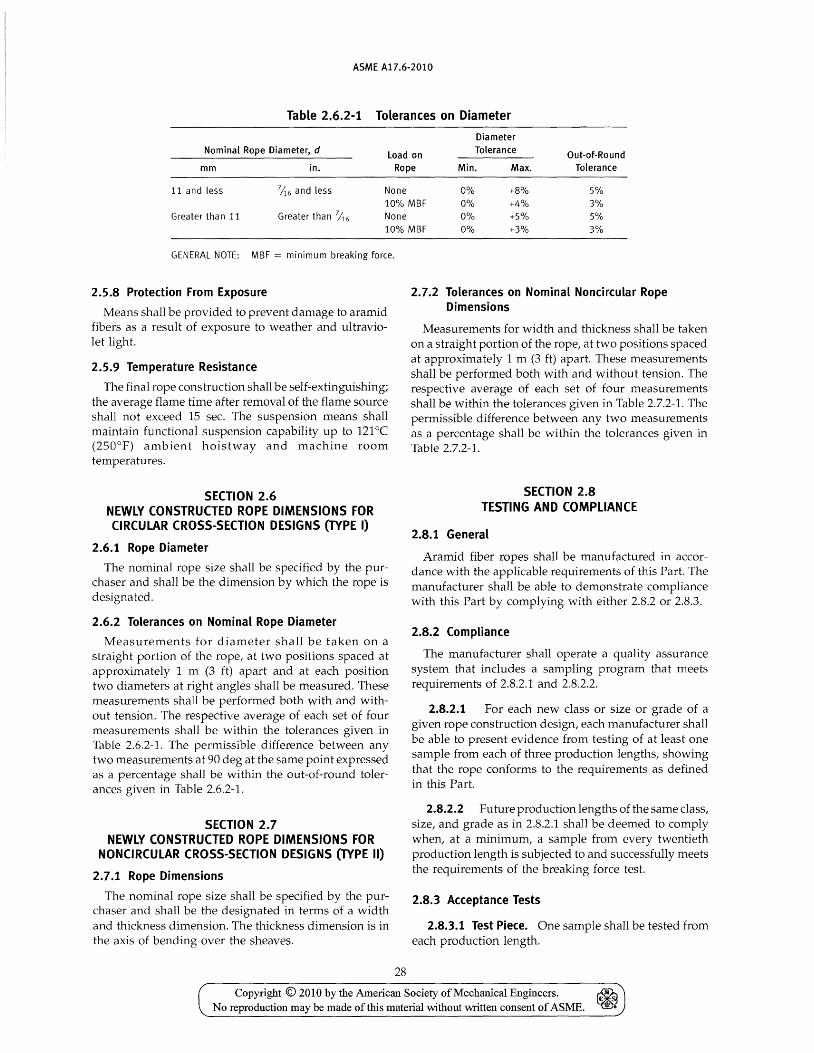
ASME A17.6·2010
Table 2.6.2-1 Tolerances on Diameter
Diameter
Nominal Rope Diameter, d load on Tolerance Out-of-Round
mm in. Rope Min. Max. Tolerance
11 and less 7iJ.6 and less None 0% +8% 5% 10% MBF 0% +4% 3%
Greater than 11 Greater than 'i16 None 0% +5% 5% 10% MBF 0% +3% 3%
GENERAL NOTE: MBF = minimum breaking force.
2.5.8 Protection From Exposure
Means shall be provided to prevent damage to aramid fibers as a result of exposure to weather and ultraviolet light.
2.5.9 Temperature Resistance
The final rope construction shall be self-extinguishing; the average flame time after removal of the flame source shall not exceed 15 sec. The suspension means shall maintain functional suspension capability up to 121°C (250°F) ambient hoistway and machine room temperatures.
SECTION 2.6 NEWLY CONSTRUCTED ROPE DIMENSIONS FOR CIRCULAR CROSS-SECTION DESIGNS (TYPE I)
2.6.1 Rope Diameter
The nominal rope size shall be specified by the purchaser and shall be the dimension by which the rope is designated.
2.6.2 Tolerances on Nominal Rope Diameter
Measurements for diameter shall be taken on a straight portion of the rope, at two positions spaced at approximately 1 m (3 ft) apart and at each position two diameters at right angles shall be measured. These measurements shall be performed both with and without tension. The respective average of each set of four measurements shall be within the tolerances given in Table 2.6.2-1. The permissible difference between any two measurements at 90 deg at the same point expressed as a percentage shall be within the out-of-round tolerances given in Table 2.6.2-1.
SECTION 2.7 NEWLY CONSTRUCTED ROPE DIMENSIONS FOR
NONCIRCULAR CROSS-SECTION DESIGNS (TYPE II)
2.7.1 Rope Dimensions
The nominal rope size shall be specified by the purchaser and shall be the designated in terms of a width and thickness dimension. The thickness dimension is in the axis of bending over the sheaves.
28
2.7.2 Tolerances on Nominal Noncircular Rope Dimensions
Measurements for width and thickness shall be taken on a straight portion of the rope, at two positions spaced at approximately 1 m (3 ft) apart. These measurements shall be performed both with and without tension. The respective average of each set of four measurements shall be within the tolerances given in Table 2.7.2-1. The permissible difference between any two measurements as a percentage shall be within the tolerances given in Table 2.7.2-1.
SECTION 2.8 TESTING AND COMPLIANCE
2.8.1 General
Aramid fiber ropes shall be manufactured in accordance with the applicable requirements of this Part. The manufacturer shall be able to demonstrate compliance with this Part by complying with either 2.8.2 or 2.8.3.
2.8.2 Compliance
The manufacturer shall operate a quality assurance system that includes a sampling program that meets requirements of 2.8.2.1 and 2.8.2.2.
2.8.2.1 For each new class or size or grade of a given rope construction design, each manufacturer shall be able to present evidence from testing of at least one sample from each of three production lengths, showing that the rope conforms to the requirements as defined in this Part.
2.8.2.2 Future production lengths of the same class, size, and grade as in 2.8.2.1 shall be deemed to comply when, at a minimum, a sample from every twentieth production length is subjected to and successfully meets the requirements of the breaking force test.
2.8.3 Acceptance Tests
2.8.3.1 Test Piece. One sample shall be tested from each production length.
Copyright © 2010 by the American Society of Mechanical Engineers. ~ No reproduction may be made ofthis material without written consent of ASME. ~

ASME A17.6-2010
Table 2.7.2·1 Tolerances on Dimensions
Thickness Nominal Rope Depth, d Load on Tolerance Width Tolerance
mm in. Rope Min. Max. Min. Max.
11 and less 7/16 and less None 0% +5% 0% +3% 10% MBF 0% -5% 0% -3%
Greater than 11 Greater than 7;;6 None 0% +5% 0% +3% 10% MBF 0% -5% 0% -3%
GENERAL NOTE: MBF = minimum breaking force.
2.8.3.2 Test Verification. When requested, the manufacturer shall allow the purchaser or their representative the opportunity to witness acceptance tests or to examine test records to verify compliance with this Part.
NOTE: Examples of acceptable quality assurance systems are API Ql, ANSI/ ASQC Q9001, and ISO 9001.
SECTION 2.9 REPLACEMENT CRITERIA
2.9.1 Replacement of Ropes
Replacement of all aramid fiber suspension and compensation ropes shall conform to the requirements of 2.9.1.1 through 2.9.1.6.
2.9.1.1 Replacement ropes shall be as specified by the original elevator manufacturer or be at least equivalent in strength, weight, and design.
2.9.1.2 Ropes that have previously been installed and used on another installation shall not be reused.
2.9.1.3 When replacing suspension or compensating ropes, all ropes in a set shall be replaced, except as permitted by 2.9.3.
2.9.1.4 The ropes in the set shall be new, all from the same manufacturer and of the same material, grade, construction, and diameter.
2.9.1.5 Data tags conforming to ASME A17.1/ CSA B44, requirement 2.20.2.2 shall be applied.
2.9.1.6 Suspension or compensating rope fastenings shall conform to ASME A17.1/CSA B44 requirement 2.20.9.
2.9.2 Replacement Due to Wear
(a) Replacement due to wear shall be considered in either of the following categories:
(1) normal wear of the rope cover and fatigue limit (2) internal abrasive wear limit of the load carrying
strands (b) The entire set of ropes shall be replaced when
(1) the elevator rope cover, through wear or damage, results in any load carrying yarn wear or damage; or
(2) the residual strength criterion is reached
29
2.9.3 Replacement Due to Damage
The suspension or compensating rope shall be replaced when load-carrying yarns are damaged by an exterior source. Damage to the rope cover itself is not a criterion for replacement as long as load-carrying yarns have not been damaged or exposed to wear. If one rope of a set is damaged during installation or acceptance testing prior to being subjected to elevator service, it is permissible to replace the damaged rope only. In all other cases, the entire set must be replaced.
2.9.3.1 The rope data for the replacement rope must correspond to the rope data specified in ASME A17.1/CSA B44, requirement 2.20.2.2.
2.9.3.2 The replacement rope shall be provided with a data tag conforming to ASME A17.1/CSA B44, requirement 2.20.2.2.
2.9.3.3 The suspension ropes, including the damaged rope, shall not have been shortened since their original installation.
2.9.3.4 The dimensions of any of the remaining ropes shall comply with Table 2.6.2-1 or Table 2.7.2.-1.
2.9.3.5 The tension of the new replacement rope shall be checked and adjusted as necessary at semimonthly intervals over a period of not less than 2 mo after installation. If proper equalization of the rope tension cannot be maintained after 6 mo, the entire set of suspension ropes shall be replaced.
2.9.3.6 The replacement rope shall be provided with the same type of suspension rope fastening used with the other ropes.
2.9.3.7 The rope shall be new, from the same manufacturer, and of the same material, grade, construction, and dimensions.
2.9.4 Replacement Due to Residual Strength Criterion
The elevator manufacturer, using information from the rope manufacturer and considering the application, shall establish the residual strength criterion to ensure that the residual strength of the aramid fiber rope is not less than 60% of the rated breaking force at the time of replacement.
Copyright © 2010 by the American Society of Mechanical Engineers. ~ ~ No reproduction may be made of this material without written consent of ASME.

ASME A17.6·2010
Part 3 Noncircular Elastomeric Coated Steel Suspension Members
for Elevators
SECTION 3.1 SCOPE
Part 3 covers the general requirements for noncircular elastomeric coated steel suspension members for suspension and compensation applications on elevators within the Scope of ASME A17.1/CSA B44.
NOTE: This Part is written in SI units recognized by the ASME A17.1/CSA B44 Code.
SECTION 3.2 REFERENCES
This Standard incorporates by dated or undated reference, provisions from other publications. These normative references are cited at their appropriate place in the text and the publications are listed. For dated references, subsequent amendments to or revisions of any of these publications apply to this Standard only when incorporated by amendment or revision. For undated references, the latest edition would apply.
3.2.1 ASTM Standards
ASTM D 395, Standard Test Methods for Rubber Property - Compression Set
ASTM D 624, Standard Test Method for Tear Strength of Conventional Vulcanized Rubber and Thermoplastic Elastomers
ASTM D 1456, Standard Test Method for Rubber Property - Elongation at Specific Stress
ASTM D 2240, Standard Test Method for Rubber Property - Durometer Hardness
ASTM D 2969, Standard Test Methods for Steel Tire Cords
ASTM D 5963, Standard Test Method for Rubber Property - Abrasion Resistance (Rotary Drum Abrader)
Publisher: American Society for Testing and Materials (ASTM), 100 Barr Harbor Drive, West Conshohocken, PA 19428-2959 (www.astm.org)
3.2.2 ISO Standard
ISO 9001, Quality management systems - Requirements
Publisher: International Organization for Standardization (ISO), 1 ch. de la Voie-Creuse, Case
30
posta Ie 56, CH-1211, Geneve 20, Switzerland/Suisse (www.iso.org)
3.2.3 Miscellaneous Standards
ASME A17.1/CSA B44 (latest edition), Safety Code for Elevators and Escalators
ASME A17.2 (latest edition), Guide for Inspection of Elevators, Escalators, and Moving Walks
Publisher: The American Society of Mechanical Engineers (ASME), Three Park Avenue, New York, NY 10016-5990; Order Department: 22 Law Drive, P.O. Box 2300, Fairfield, NJ 07007-2300 (www.asme.org)
API Spec. Q1, Specification for Quality Programs for the Petroleum, Petrochemical and Natural Gas Industry
Publisher: American Petroleum Institute (API), 1220 L Street, NW, Washington, DC 20005-4070 ( www.api.org)
ANSI! ASQC Q9001, Quality management systems -Req uiremen ts
Publisher: American Society for Quality (ASQ), P.O. Box 3005, Milwaukee, WI 53201-3005 (www.asg.org)
SECTION 3.3 TERMINOLOGY
3.3.1 Descriptions of Terms Specific to Part 3
3.3.1.1 Steel Cord. An assembly of steel strands each comprising several steel wires. The strands are helically laid around a central core strand. See 1.3.1.4.2. For definition of wire, see 1.3.1.2. For definition of strand, see 1.3.1.3.1.
3.3.1.2 Noncircular Elastomeric Coated Steel Suspension Member. A noncircular suspension member, such as an elastomeric coated steel belt comprising several steel cords arranged in parallel and molded within a coating.
3.3.1.3 Cord Cores. The central elements, usually of steel (unless specified otherwise) around which the strands are helically laid.
3.3.1.4 Noncircular Elastomeric Coated Steel Suspension Member Grade. A level of requirement of the breaking force of the noncircular elastomeric coated
Copyright © 2010 by the American Society of Mechanical Engineers. ~ No reproduction may be made of this material without written consent of ASME. ~

ASME A17.6-2010
steel suspension member, which is designated by the minimum breaking force in kilonewton (kN).
3.3.2 Dimensional Characteristics
3.3.2.1 Steel Cords
3.3.2.1.1 Cord Diameter. The diameter of a circle that circumscribes the cross section of a cord. This diameter is used for evaluating diameter ratios.
3.3.2.1.2 Cord Lay Length. That distance measured parallel to the longitudinal member axis, in which the outer strands of the cord make one complete turn about the axis of the cord.
3.3.2.1.3 Number of strands in a cord.
3.3.2.1.4 Number of steel wires in a strand.
3.3.2.2 Molded Noncircular Elastomeric Coated Steel Suspension Member
3.3.2.2.1 Number of steel cords in a noncircular elastomeric coated steel suspension member.
3.3.2.2.2 Cord Pitch. The spacing between adjacent cord centerlines in the noncircular elastomeric coated steel suspension member.
3.3.2.2.3 Noncircular Elastomeric Coated Steel Suspension Member Width. The dimension of the crosssection of the molded noncircular suspension member, measured in the direction of sheave axis.
3.3.2.2.4 Noncircular Elastomeric Coated Steel Suspension Member Thickness. The dimension of the cross-section of the molded noncircular suspension member measured perpendicular to the direction of the sheave axis.
3.3.3 Mechanical Properties
3.3.3.1 Steel Cord, Minimum Breaking Force (MBF). Specified value that the actual (measured) steel cord breaking force must meet or exceed in a prescribed tensile test.
3.3.3.2 Rated Breaking Force. A value of breaking force, less than or equal to minimum breaking force, published by the manufacturer to which AS ME A17.1/ CSA B44 rope factors of safety are applied.
3.3.3.3 Noncircular Elastomeric Coated Steel Suspension Member, Minimum Breaking Force. Specified value that the actual (measured) noncircular elastomeric coated steel suspension member breaking force must meet or exceed in a prescribed tensile test.
3.3.3.4 Noncircular Elastomeric Coated Steel Suspension Member Stretch (Extension)
3.3.3.4.1 Constructional Stretch. Amount of extension that is attributed to the initial bedding down
31
of the wires within strands and the strands within the cords due to member loading.
3.3.3.4.2 Elastic Stretch. Amount of recoverable extension that follows Hooke's Law, within certain limits due to application of load.
3.3.3.4.3 Permanent Stretch. Nonelastic extension.
3.3.3.5 Residual Strength. The actual breaking strength of a suspension member at any time during its operational life cycle.
NOTE: The residual strength will be reduced as the suspension member is used and is subjected to wear.
3.4.1 Construction
SECTION 3.4 MATERIAL
3.4.1.1 Steel wire used in cord construction may be carbon or alloy steel manufactured to meet the tensile strength properties and durability requirements specified by the noncircular elastomeric coated steel suspension member manufacturer or user. Specified wire tensile strength values shall be within the range stated as follows. Mechanical properties shall be measured to ASTM D 2969-89.
Specified Tensile Strength, N/nnu2
Min. Max.
1,570 3,500
3.4.1.2 Steel wires or cords may be plated with corrosion reducing materials as required by the noncircular elastomeric coated steel suspension member manufacturer or user.
3.4.1.3 Elastomeric coating material may be polyurethane or other suitable material that meets the durability, flexibility, and traction requirements specified by the noncircular elastomeric coa ted steel suspension member manufacturer or user. Mechanical properties to be measured to ASTM D 1456, D 2240, D 5963, D 395, or equivalents of these.
SECTION 3.5 PROPERTIES AND TOLERANCES
3.5.1 Classification
Noncircular elastomeric coated steel suspension member shall be classified by the wid th and thickness, number of cords, cord diameter, and coating material.
3.5.2 Cord Core
Cords shall be constructed with a steel core unless specified otherwise. Other cores shall be determined by agreement between supplier and purchaser.
Copyright © 2010 by the American Society of Mechanical Engineers. ~ ~ No reproduction may be made of this material without written consent of ASME.

ASME A17.6-2010
Table 3.5.7-1 Tolerances on Nominal Noncircular Elastomeric Coated Steel Suspension
Members Sizes
Tolerance Load on
Width Thickness Suspension Member, kN Min. Max. Min. Max.
o to 10% MBF -5% +5% -5% +5%
3.5.3 Noncircular Elastomeric Coated Steel Suspension Member Grade
See 3.3.1.4.
3.5.4 Cord Lay
Flatness
3%
The cord lay shall be specified between purchaser and manufacturer.
3.5.5 Noncircular Elastomeric Coated Steel Suspension Member Mass
The suspension member mass shall be specified in kg/m (lb/ft) by the manufacturer.
3.5.6 Noncircular Elastomeric Coated Steel Suspension Member Length
The actual length of noncircular elastomeric coated steel suspension member supplied expressed in meters shall be specified by the manufacturers subject to tolerances agreed upon by manufacturer and purchaser.
3.5.7 Dimensional Tolerances
Tolerances on cord diameter shall be agreed upon by manufacturer and purchaser. The dimensional tolerances of the noncircular elastomeric coated steel suspension members shall be as indicated in Table 3.5.7-1.
SECTION 3.6 TESTING AND COMPLIANCE
3.6.1 General
Noncircular elastomeric coated steel suspension members shall be manufactured in accordance with the applicable requirements of this Standard. The manufacturer shall be able to demonstrate compliance with this Part by complying with either 3.6.2 or 3.6.3.
3.6.2 Compliance
The manufacturer shall operate a quality assurance system that includes a sampling program that meets requirements of 3.6.2.1 and 3.6.2.2.
3.6.2.1 For each new class, size, or grade of a given noncircular elastomeric coated steel suspension member design, each manufacturer shall be able to present evidence from testing of at least one sample from each of
32
three production lengths, showing that the noncircular elastomeric coated steel suspension member conforms to the minimum requirements as defined in this Part.
3.6.2.2 Future production lengths of the same class, size, and grade as in 3.6.2.1 shall be deemed to comply when, at a minimum, a sample from every twentieth production length is subjected to and successfully meets the requirements of the breaking force test.
3.6.3 Acceptance Tests
3.6.3.1 Test Piece. One sample shall be tested from each production length.
3.6.3.2 Test Verification. When requested, the manufacturer shall allow the purchaser or his representative the opportunity to witness acceptance tests or to examine test records to verify compliance with this Part.
NOTE: Examples of acceptable quality assurance systems are API Ql, ANSI! ASQC Q9001, and ISO 9001.
SECTION 3.7 REPLACEMENT CRITERIA
3.7.1 Replacement of Members
Replacement of all noncircular elastomeric coated steel suspension members shall conform to the requirements of 3.7.1.1 through 3.7.1.6.
3.7.1.1 Replacement members shall be as specified by the original elevator manufacturer or be at least equivalent in strength, weight, and design.
3.7.1.2 Members that have previously been installed and used on another installation shall not be reused.
3.7.1.3 When replacing suspension or compensating members, all members in a set shall be replaced, except as permitted by 3.7.3.
3.7.1.4 The members in the set shall be new, all from the same manufacturer and of the same material, grade, construction, and dimensions.
3.7.1.5 Data tags conforming to ASME A17.1/ CSA B44, requirement 2.20.2.2 shall be applied.
3.7.1.6 Suspension or compensating member fastenings shall conform to ASME A 17.1/ CSA B44, requirement 2.20.9.
3.7.2 Replacement Due to Wear
The noncircular elastomeric coated steel suspension member shall be replaced when
(a) the steel cords, strands or wires break through the elastomeric coating;
(b) the elastomeric coating has been worn so that any steel cord is exposed to wear; or
Copyright © 2010 by the American Society of Mechanical Engineers. No reproduction may be made ofthis material without \Witten consent of ASME.

ASME A17.6-2010
(c) there is evidence of red rouging on any part of the noncircular elastomeric coated steel suspension member except where continuous monitoring of the steel cords for the residual strength criteria of ASME A17.1/CSA B44, requirement 2.20.8.3 is applied. (In noncircular elastomeric coated steel suspension members manufactured with transverse slots, rouging will first be evident in the slots, however not all red discoloration is rouging).
If anyone member is replaced due to wear, the complete set of similarly utilized members on that elevator shall be replaced.
3.7.3 Replacement Due to Damage
The noncircular elastomeric coated steel suspension member shall be replaced when load-carrying cords are damaged by an exterior source. Damage to the member coating itself is not a criterion for replacement as long as load-carrying cords have not been damaged or exposed to wear. If one member of a set is damaged during installation or acceptance testing prior to being subjected to elevator service, it is permissible to replace the damaged member only. In all other cases, the entire set must be replaced.
3.7.3.1 The member data for the replacementmember must correspond to the member data specified in ASME A17.1/CSA B44, requirement 2.20.2.2.
3.7.3.2 The replacement member shall be provided with a data tag conforming to ASME A17.1/CSA B44, requirement 2.20.2.2.
33
3.7.3.3 The suspension members, including the damaged member, shall not have been shortened since their original installation.
3.7.3.4 The dimensions of any of the remaining members shall comply with Table 3.5.7-1.
3.7.3.5 The tension of the new replacement member shall be checked and adjusted as necessary at semi monthly intervals over a period of not less than 2 mo after installation. If proper equalization of the member tension cannot be maintained after 6 mo,the entire set of suspension members shall be replaced.
3.7.3.6 The replacement member sha 11 be provided with the same type of suspension member fastening used with the other members.
3.7.3.7 The non circular elastomeric coated steel suspension member shall be replaced if the member is permanently kinked, bent, or deformed in any way.
3.7.4 Replacement Due to Residual Strength Criterion
The noncircular elastomeric coated steel suspension member shall be replaced if the residual strength criterion of the load-carrying cords is reached.
The elevator manufacturer using information from the noncircular elastomeric coated steel suspension member manufacturer and considering the application, shall establish the residual strength criterion to ensure that the residual strength of the noncircular elastomeric coated steel suspension member is not less than 60% of the rated breaking force at the time of replacement.
Copyright © 2010 by the American Society of Mechanical Engineers. No reproduction may be made of this material without written consent of ASME.

INTENTIONALLY LEFT BLANK
34
Copyright © 2010 by the American Society of Mechanical Engineers. ~ € S
No reproduction may be made of this material without written consent of ASME. m •

ASME A17.6-2010
NONMANDATORY APPENDIX A INSPECTION AND REPLACEMENT OF STEEL WIRE ROPES
See Fig. A-I for the inspection and replacement of steel wire ropes.
35
Copyright © 2010 by the American Society of Mechanical Engineers. No reproduction may be made of tbis material without \Witten consent of ASME.

The rope is okay for use until next inspection
ASME A17.6-2010
Fig. A-l Inspection and Replacement of Steel Wire Ropes
Yes
Yes
36
Replace ropes
Copyright © 2010 by the American Society of Mechanical Engineers. ~ No reproduction may be made of this material without \Witten consent of ASME. ~
INTENTIONALLY LEFT BLANK
Copyright © 2010 by the American Society of Mechanical Engineers. ~ E- S
No reproduction may be made oftms material without written consent of ASME. 1Il •

Copyright © 2010 by the American Society of Mechanical Engineers. ~ No reproduction may be made of this material without "Mitten consent of ASME. ~
ISBN 978-0-7918-3287-5
9 780791 832875
IIII~IIIIIIIIII~IIIIII~II~I~I A20110