Embed Size (px)
Citation preview
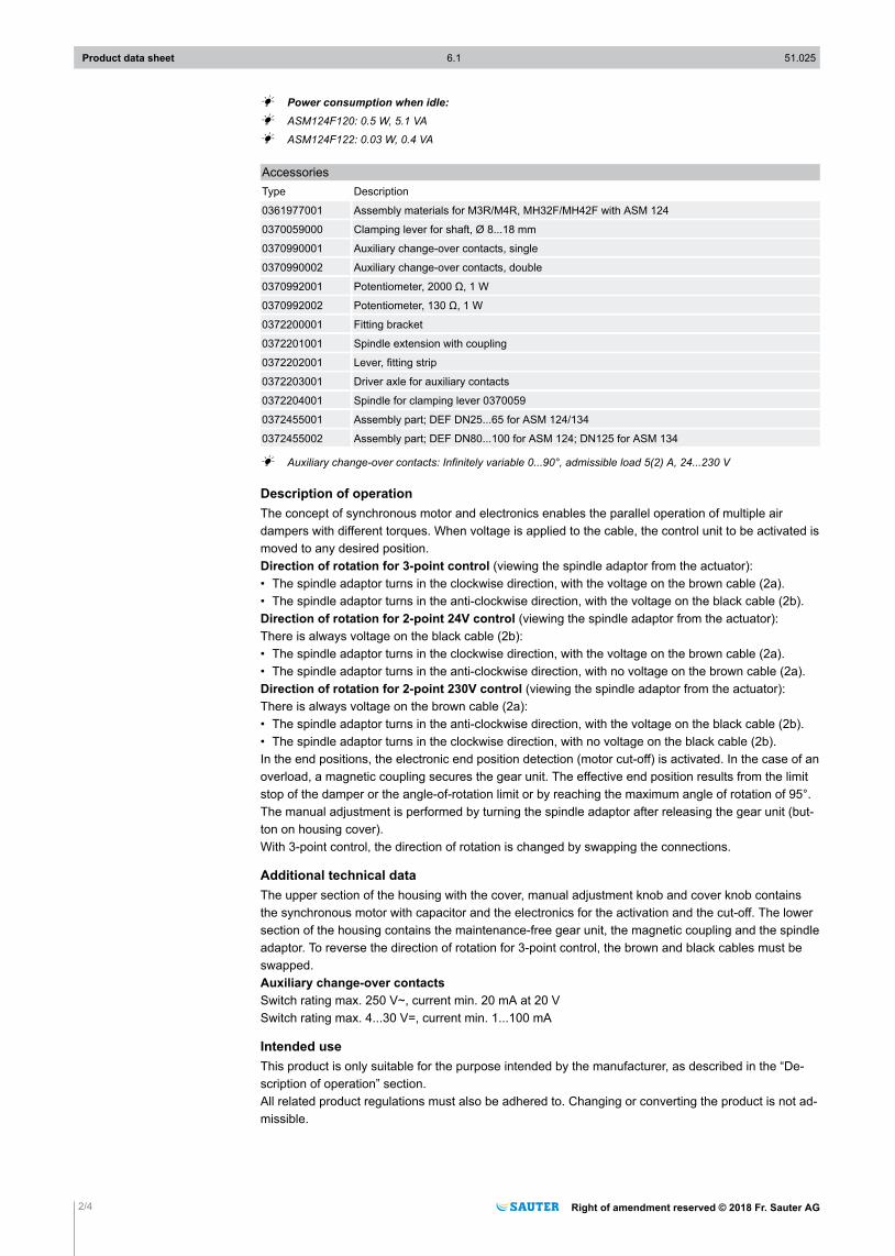
ASM 124: Damper actuator
How energy efficiency is improvedTorque-dependent cut-off facility for efficient usage of energy
Features• For operating air dampers, shut-off dampers, butterfly valves and multi-leaf dampers• For controllers with switching (2- and 3-point) output• Synchronous motor with electronic activation and cut-out• Maintenance-free gear unit• Electronic end position detector and motor cut-off• Self-centring spindle adapter for fitting onto damper spindle• Gear unit can be disengaged to position the damper and for manual adjustment• Suitable for all fitting positions• Threaded holes (M5) for fitting to bracket• Version with halogen-free cable on demand
Technical data
Power supplyPower supply 230 V~ ±15%, 50...60 HzPower supply 24 V~ ±20%, 50...60 Hz
ParametersTorque and holding torque 18 NmRunning time for 90° 120 sAngle of rotation Max. 95°Admissible damper shaft Ø 12...20 mm, □ 10...16 mmAdmissible damper shaft (hardness) max. 300 HVOperating noise < 30 dB (A)Response time 200 ms
Ambient conditionsAdmissible ambient temperature –20...55 °CAdmissible ambient humidity < 95% rh, no condensation
ConstructionWeight 1.2 kgHousing Lower section black, upper section
yellowHousing material Fire-retardant plasticPower cable 1.2 m long, 3 × 0.75 mm²
Standards and directivesType of protection IP40 (EN 60529), IP43 (EN 60529),
IP54 (EN 60529), IP55 (EN 60529)Protection class 230 V II (EN 60730)Protection class 24 V III (EN 60730)EMC Directive 2014/30/EU EN 61000-6-1, EN 61000-6-2
EN 61000-6-3, EN 61000-6-4Low-Voltage Directive 2014/35/EU EN 60730-1, EN 60730-2-14Over-voltage categories IIIDegree of contamination IIMode of operation Type 1 AB (EN 60730)
Type 1 C (EN 60730)Software A (EN 60730)
Overview of typesType Voltage Power consumption
ASM124F120 230 V~ 2.9 W, 5.6 VA
ASM124F122 24 V~ 2.3 W, 2.4 VA
Product data sheet 6.1 51.025
Right of amendment reserved © 2018 Fr. Sauter AG 1/4
ASM124F12
A Power consumption when idle:A ASM124F120: 0.5 W, 5.1 VA
A ASM124F122: 0.03 W, 0.4 VA
AccessoriesType Description
0361977001 Assembly materials for M3R/M4R, MH32F/MH42F with ASM 124
0370059000 Clamping lever for shaft, Ø 8...18 mm
0370990001 Auxiliary change-over contacts, single
0370990002 Auxiliary change-over contacts, double
0370992001 Potentiometer, 2000 Ω, 1 W
0370992002 Potentiometer, 130 Ω, 1 W
0372200001 Fitting bracket
0372201001 Spindle extension with coupling
0372202001 Lever, fitting strip
0372203001 Driver axle for auxiliary contacts
0372204001 Spindle for clamping lever 0370059
0372455001 Assembly part; DEF DN25...65 for ASM 124/134
0372455002 Assembly part; DEF DN80...100 for ASM 124; DN125 for ASM 134
A Auxiliary change-over contacts: Infinitely variable 0...90°, admissible load 5(2) A, 24...230 V
Description of operationThe concept of synchronous motor and electronics enables the parallel operation of multiple airdampers with different torques. When voltage is applied to the cable, the control unit to be activated ismoved to any desired position.Direction of rotation for 3-point control (viewing the spindle adaptor from the actuator):• The spindle adaptor turns in the clockwise direction, with the voltage on the brown cable (2a).• The spindle adaptor turns in the anti-clockwise direction, with the voltage on the black cable (2b).Direction of rotation for 2-point 24V control (viewing the spindle adaptor from the actuator):There is always voltage on the black cable (2b):• The spindle adaptor turns in the clockwise direction, with the voltage on the brown cable (2a).• The spindle adaptor turns in the anti-clockwise direction, with no voltage on the brown cable (2a).Direction of rotation for 2-point 230V control (viewing the spindle adaptor from the actuator):There is always voltage on the brown cable (2a):• The spindle adaptor turns in the anti-clockwise direction, with the voltage on the black cable (2b).• The spindle adaptor turns in the clockwise direction, with no voltage on the black cable (2b).In the end positions, the electronic end position detection (motor cut-off) is activated. In the case of anoverload, a magnetic coupling secures the gear unit. The effective end position results from the limitstop of the damper or the angle-of-rotation limit or by reaching the maximum angle of rotation of 95°.The manual adjustment is performed by turning the spindle adaptor after releasing the gear unit (but-ton on housing cover).With 3-point control, the direction of rotation is changed by swapping the connections.
Additional technical dataThe upper section of the housing with the cover, manual adjustment knob and cover knob containsthe synchronous motor with capacitor and the electronics for the activation and the cut-off. The lowersection of the housing contains the maintenance-free gear unit, the magnetic coupling and the spindleadaptor. To reverse the direction of rotation for 3-point control, the brown and black cables must beswapped.Auxiliary change-over contacts Switch rating max. 250 V~, current min. 20 mA at 20 VSwitch rating max. 4...30 V=, current min. 1...100 mA
Intended useThis product is only suitable for the purpose intended by the manufacturer, as described in the “De-scription of operation” section.All related product regulations must also be adhered to. Changing or converting the product is not ad-missible.
Product data sheet 6.1 51.025
2/4 Right of amendment reserved © 2018 Fr. Sauter AG
Engineering and fitting notesThe actuator can be fitted in any position and can be plugged directly onto the damper spindle andfixed by means of the self-centring clamping lever.
)NoteThe housing must not be opened.
The maximum accessory equipment for an actuator is: 1 single auxiliary contact or 1 double auxiliarycontact or 1 potentiometer. The angle of rotation can be limited to between 0° and 90° in 5° stages.The limitation is defined by means of a setting disc (under the coupling piece). This coupling piece issuitable for Ø 12...20 mm and 10...16 mm damper spindles.
Outdoor installationWe recommend protecting the devices from the weather if they are installed outside buildings.
DisposalWhen disposing of the product, observe the currently applicable local laws.More information on materials can be found in the Declaration on materials and the environment forthis product.
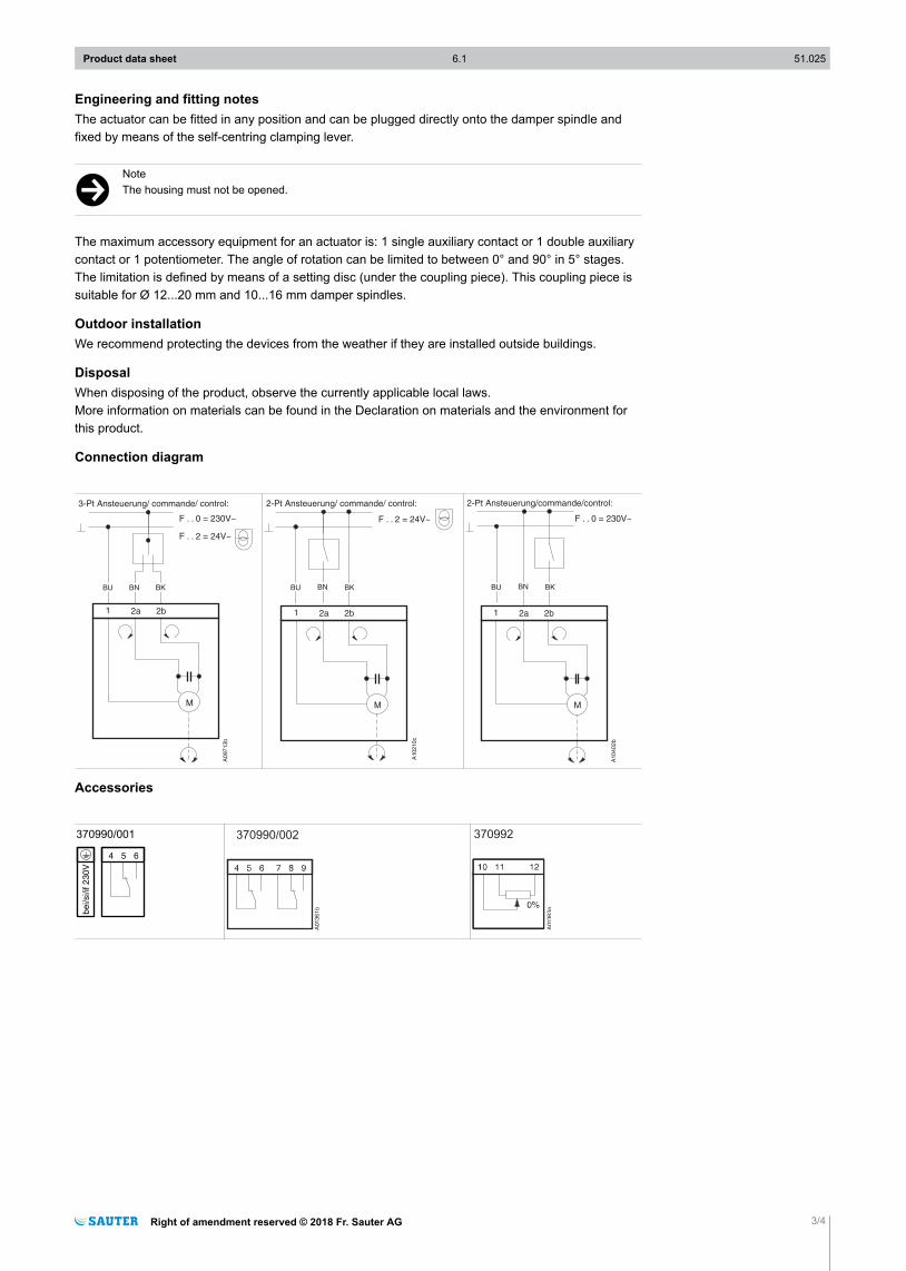
Connection diagram
Accessories
370990/001
4 5 6
be
i/si/if 2
30
V
370990/002
A01361b
370992
A01363a
Product data sheet 6.1 51.025
Right of amendment reserved © 2018 Fr. Sauter AG 3/4
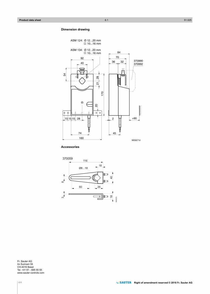
Dimension drawing
92
40
70
84
36 32
54
28
21
17
0
>90215
20
15 15 28
74
160
45
M05671d
370990
370992
ASM 1 4: Ø 1 ...20 mm
10...16 mm
2 2
ASM 134: Ø 12...20 mm
10...16 mm
Accessories
40
116
18
60 26
18
83
M0
029
7b
370059
Ø8...18
Product data sheet 6.1 51.025
4/4 Right of amendment reserved © 2018 Fr. Sauter AG
Fr. Sauter AGIm Surinam 55CH-4016 BaselTel. +41 61 - 695 55 55www.sauter-controls.com