Embed Size (px)
Citation preview

Design, Analysis and Construction a Novel NN Switching Modulation Method for Utilizing in Matrix Converter
A.Siadatan*1, E.Afjei2
1-Department of Electrical Engineering, West Tehran Branch, Islamic Azad University, Tehran, IRAN.
2- Department of Electrical Engineering, ShahidBeheshti University G.C, Tehran, IRAN.
Abstract:In this paper, a novel switching method of bi-directional switches using Venturini’s method by employing Neural Network (NN) and based on duty cycles is presented. The need for standard soft switching calculation is also eliminated and a new modulation matrix is calculated for the constant output frequency and voltage magnitude. Simulation results are presented for inductive and resistive loads. Finally, a 3 × 3 Matrix Converter (MC)is constructed and the circuit is tested in laboratory. Our proposed modulation technique is in complete agreement with the standard simulations results which show the validity of the proposed method.
Keywords: Matrix Converter (MC), Neural Network (NN), ac-ac converter, pulse width modulation (PWM)
1-Introduction:The matrix converter (MC) is an array of controlled semiconductor switches which connects the three-phase source to the three-phase load directly. MC has several attractive features which have been investigated in the last two decades. In the last few years, there has been a vast amount of research on MC, bringing this topology closer to the industrial application [1].Recently, great attention has been paid to
the use of matrix converter technology for motor drive applications, with particular interest being shown by Siemens, Rockwell and Yaskawa [2].In [3], a new type of AC/AC power converter is proposed. The proposed converter is capable of direct AC/AC power conversion and, except for a few small snubber elements; it does not require the use of any input inductors or a DC-link capacitor. In [4], the vector control of two-phase induction motor drives with using matrix converter topologies is investigated. The aim is to reach a set of switches that can produce two phases’ voltage and current in order to be used in an induction motor. In [5], a novel approach is proposed to extend the range of speed control and to eliminate the harmonic contents of the output voltage of the two-phase inverter-fed induction motor. These are both disadvantages of a conventional two-step driving system. Phase-difference control is used to extend the range of speed control and to simplify the driving circuit. A microprocessor-based PWM technique is used to eliminate the harmonic content of output voltage. The algorithm for phase-difference control is presented. The performance of a two-phase induction motor run by the phase-difference control method is analyzed.In applications where only voltage regulation is needed, a direct PWM ac-ac converter is suggested which has several attractive features as single stage

conversion, simple and easy to control topology, small size and lower cost.In [6], the maximum input-output transformer ratio, or output voltage ability, of direct AC-AC pulse-width-modulated converters is explored. An intrinsic limit, independent of the control algorithm, is found. A suitable novel converter control algorithm is discussed which achieves such maximum output amplitude ability and displays some interesting features. In [7], a unified pulse width modulation (PWM) algorithm is presented that is derived from AC-AC matrix power converter theory. The algorithm can be used to implement either a voltage source or a current source inverter, using only conventional bridge topologies. The resultant modulation strategy produces minimal low-order AC harmonics, yet it is readily capable of being computed online in a single switching cycle by a low-cost microprocessor at switching frequencies of up to several kilohertz. In [8], a phase-difference angle (PDA) controlled pulsewidth-modulated (PWM) inverter is proposed for a two-phase induction motor adjustable speed drive. Output waveforms are fixed over the whole operating range of the motor. The motor torque is controlled not by the modulation of the phase voltage, but by the PDA. Based on the selected harmonic elimination (SHE) PWM technique, the commutation angles of the output voltage are calculated. It is worth mentioning that real time implementation of PWM switching algorithms is difficult. NN or Artificial NN (ANN),where the latter is more precise than the former, represent a technology rooted in neuroscience, mathematics, statistics, physics, computer sciences and engineering. NN finds applications in different fields as modeling, time series analysis, pattern recognition, signal processing and control by virtue of an
important property which is the ability of learning from the input data. [9]Switching function optimizing is of paramount importance in MC to achieve low harmonic distortion.In [10] using NN technology is suggested to satisfy low harmonic distortion.A novel switching of the bi-direction switches according to duty cycles found by Venturini in conjunction with soft switching during transient periods.This process can be formulated by applying Venturini’s plus NN. Finding modulation matrix to drive switches is a critical issue in matrix converter. Since finding the switching time is the main problem, the NN proposed in this paper presents a new modulation matrix which renders less unwanted harmonics in MC output.In this paper, a novel switching method of the bi-directional switches is presented which is based on duty cycles using Venturini method and with soft switching during transient periods by employing NN. The method is then used to design and construct a 3 × 3 MC and the circuit is tested in laboratory.The rest of the paper is organized as follows: Section 2 details the structure of the proposed MC system, section 3presents the proposed method, afterwards in section 4 the performance of our approach is assessed by a simulation set up, thereafter the optimum results of the proposed MC is presented in Section 5.Section 6 provides the conclusion of this paper.
2- Structure of the proposed MC:The proposed 3 × 3 MC is an ac-ac converter with 3 input phases and 3 output phases, respectively. It consists of 9 bi-directional switches connecting inputs to outputs. The structure of a 3 × 3 MC and different types of bi-directional switches are

shown in Fig.1. The need for filter at output is bypassed in our proposed method, since the load is considered inductive and resistive; however, the output filter is used in some cases which rendersgood ripple less output waveform. Each output waveform is synthesized by sequential piecewise sampling of the input waveforms; the sampling rate is set much higher than both input and output frequencies and the duration of each sample is controlled as the average value of the output waveform within each sample cycle tracks the desired output waveform.
(a)
(b)Fig.1: (a): The structure of a 3 × 3 MC (b): Different types of bi-directional switches
In order to obtain matrix [M] which is known as modulation matrix, the following equations must be solved:[v¿¿o (t)]=[M (t)]×[v¿¿ i( t)]¿ ¿ (1)
[ i¿¿ i(t )]=[M (t)]T×[i¿¿o( t)]¿ ¿ (2)In order to reach maximum output voltage amplitude it could be used a modified equation as follow that get help third input harmonics in calculation of switching times to reach voltage amplitude at output to 0.86Vin[5].
mkj=13[1+
2 vk v jv i
2 + 4q3√3
sin (ωi t+αi)sin (3ωi t)]
(3)For i= A,B,C and k = a,b,c and αi=0, 2π/3, 4π/3In order to simplify the calculation process because in this case reaching to the maximum voltage is not a big issue, so using the second equation that presented in equation(4) that is not getting help the input third harmonics could be very effective.The block which generates the training switching vector is shown in Fig.2.
Fig.2: The block which generates the training switching vector
The modulation method presented in [4] is as follows:
mij=t ij
T sample=1
3[1+
2vk v jv i
2 ] (4)
For i= A,B,C and j= a,b,cWhere vi is the one of input voltage and vk is one of the output phase Vi is the maximum amplitude of input voltage and T is the sample time.

3-The proposed methodSwitching process in power switching supplies like MC is of great importance. In order to get a specific output voltage in the head of the load, it is necessary to calculate equation (3) to find the switching time, however, there are some issues to overcome. One of the important issues which can prevent MC to achieve high frequency in the output is calculation times. Hence, the time consuming in such systems will be an important element which is needed to be considered. The otherimportantproblem that occurs in running power switching supplies is the activation method used in switching system applied in these kinds of power supplies. MC is one of these systems that need a specific kind of power supplyand a switching process in some occasions. One of these occasions happens when it requires changing input voltage on the load head. SinceMC should not beopen circuit or short circuit to avoid damaging switches [4].Radial basis function (RBF) neural network is used in this paper. These networks have the best efficiency when the training vectors are enough. In the presented method training vector is Venturini’s equations. Generalized Regression NN (GRNN) is a kind of radial basis network that is often used for function approximation.The GRNN is a two-layer network where the first and the second layer have radial basis and pure linear neurons, respectively. The architecture of the GRNN is presented in Fig.3.
Fig.3: The architecture of the GRNNP (The frequency): matrix of n input vectorsZ (Switching times=tij): matrix of n target class vectorsSpread: spread of radial basis functions (default = 1)
The first layer weights and biases in GRNN are set to P and 0.8326/(spread=1), also the second layer weights (W2) are set to Z.This network needs two vectors to simulate the network which are calculated using equation (4).The vector F is the whole frequency range which is used in input voltage frequency to achieve tij. Due to the 20% changes of frequency from the central frequency (50 Hz), the range of training input vector p covers the frequencies from 40 to 60 Hz.F={ f 1 , f 2 , f 3 ,…, f n } f n−f 1=20Hz (5)
WhereN is the number of neurons which are used. There is a set of switching time using equation (4) for each fi (input voltages frequency) which change the input phase on the load to overcome short circuit or open circuit. The elements of vector T are as follows:T={T 1 ,T 2 , T 3 ,…,Tm } (6)
WhereM is the number of sampling in the whole period (which is considered 20in this case).Also Tj is a column vector that includes the jth activation time for ith
frequency:

T j={t j .1t j .2..t j . n
}j=1,….,
m(in this case 20) (7)Hence, the two vectors which are used in training system to find the switching times for desired frequency are:P=F∧Z=T j (8)
Using NN to find the switching time matrix makes the switching process easier. So a small processor is required for switching algorithm implementation; since, there is only a set of switching time for the system which helps microcontroller to run the switches.
4-The simulation of the presented methodBy utilizing the designed system in simulation, the three-phase output voltage is obtained as shown in Fig.4.
Fig.4: The output three-phase voltage of the simulated MC
From Fig.5, it is clear that in case where frequency is 50 Hz, the amplitude of output current waveform is very high which shows the MC proper operation.
5-The operation results of the proposed MCThe proposed circuit is constructed in laboratory and is illustrated in Fig.6.In the proposed circuit, MC is used to drive an induction motor withP=200W and V=120v.
Fig.6: The constructed MC circuit in laboratory
The desirable voltage is achieved which has the expected frequency and amplitude of output voltage (max 0.86Vin). Fig.7 presents the output voltage of MC with three input voltages yielding two input voltages with π/2 phase difference for the two phase induction motor. It also shows that the MC input is connected to a three-phase source where the frequency is 50 Hz and the desired output voltage is set for 30 Hz.
Fig.7: The output voltages of MC
Fig.8 shows the output voltage Vab produced by MC.
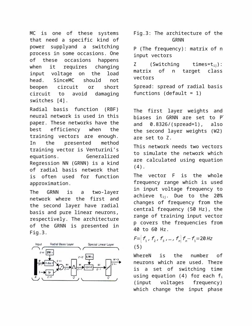
Fig.8: The output voltage Vab of MC
Output frequency is not limited to input frequency and can be changed to any desired frequency. It is clear that when this waveform is applied to an inductive load such as an induction motor, some high frequency harmonics are eliminated and the voltage envelope will be the desired sinusoidal waveform with frequency.
6-ConclusionIn this paper, a novel switching method of bi-directional switches using Venturini’s method by employing Neural Network (NN) and based on duty cycles is presented.According to the proposed modulation method, the new methodology, using ANN presented a good current and voltage waveform in the output and very low harmonic distortion. In addition, applying presented methodology eliminate the need for semi-soft switching that used a voltage or current sensor to sense the direction of current. The method is used to construct a 3 × 3 Matrix Converter (MC) and the circuit is tested in laboratory. Comparison of the standard simulations results with the new modulation technique shows the validity of the proposed method.
Reference[1] Wheeler, P.W. ; Rodriguez, J. ; Clare, J.C. ; Empringham, L. ; Weinstein, A., Matrix converters: a technology review, IEEE Transactions on Industrial Electronics, , Volume: 49 , no. 2 , , pp. 276 – 288,2002.
[2]P.Wheeler, Clare, J. ; Empringham, L. ; Apap, M. ; Bland, M., Matrix converters , Power Engineering Journal Volume: 16 , n. 6 pp. 273 – 282, 2002.
[3] Siyoung Kim ; Seung-Ki Sul ; Lipo, T.A., “Ac/Ac power conversion based on matrix converter topology with unidirectional switches” IEEE trans. Industry applications, vol. 36, no. 1, 2000, pp.139-145.
[4] Asgar, M. ; Mansourpour, S. ; Afjei, E., “Matrix Converter for two-phase induction motor application: Analysis, modeling and simulation ”, Power Electronics, Drive Systems and Technologies Conference (PEDSTC), 2011,pp. 246 - 250.
[5] Dohyun Jang ; Gueesoo Cha ; Doekgun Kim ; Jongsoo Won “ phase difference control of 2 -phase inverter -fed induction motor”,20th Annual IEEE Power Electronics Specialists Conference (PESC) , vol. 2, no. 1, pp.571-578, 1989.
[6] Alesina, A. ; Venturini, M.” analysis and design of optimum amplitude nine-switch direct AC-AC converters ” IEEE Trans. Power electronic, vol. 4,issue 1,pp. 101-112, 1989.
[7] Holmes D. G. “a unified modulation algorithm for voltage and current source inverters based on AC-AC matrix converter theory” IEEE trans. Industry applications, vol. 28, no. 1, 1992.
[8] Do-Hyun Jang” voltage, Frequency and phase-difference angle control of PWM inverters- fed two- phase induction motor ” IEEE Trans. Power electronic, vol. 9, n.4, pp.377-383, 1994.
[9] H. Karaca,”Control of venturini method based matrix converter in input voltage Variations” IMECS 2009, hongkong.
[10] Mhango, L.M.C. ; Creighton, G.K., “Novel two- phase inverter- fed induction- motor drive” IET proc. B, Electric Power Applications, vol. 131,n.3,pp. 99-104, 1984.