Embed Size (px)
Citation preview

Energy Efficient Kitchen Ventilation Design
1
Tyler SchillingGreenheck Fan Corporation

Learning Objectives
• Kitchen design objectives• Kitchen control technology• DCV application and design
2

Design Objectives
• Comply with local and industry codes– IMC Section 507 – Commercial Kitchen Hoods– NFPA 96 - Standard for Ventilation Control and Fire
Protection of Commercial Cooking Operations– ASHRAE 90.1 - Energy Standard for Buildings
• Minimize cost
3
507.1 General.Commercial kitchen exhaust hoods shall comply with the requirements of this section. Hoods shall be Type I or Type II and shall be designed to capture and confine cooking vapors and residues.
Exception:1. Factory-built commercial exhaust hoods which are tested in accordance with UL 710, listed, labeled and installed in accordance with Section 304.1 shall not be required to comply with Sections 507.4, 507.7, 507.11, 507.12, 507.13, 507.14 and 507.15.
IMC Section 507Commercial Kitchen Hoods
4

5
Scope of UL 710
1.1 These requirements cover exhaust hoods intended for placement over commercial cooking equipment. Exhaust hoods with and without exhaust dampers are covered by these requirements.
1.3 All exhaust hoods are intended for use with fire extinguishing system units.
5

...shall not be required to comply with
Sections507.4 - Type I materials507.7 - Hood joints, seams and penetrations507.11 - Grease filters507.12 - Canopy size and location507.13 - Capacity of hoods507.14 – Non-canopy size and location507.15 - Exhaust outlets
IMC Section 507Commercial Kitchen Hoods
• Factory-build kitchen exhaust hoods which are tested in accordance with UL 710
6

7
Capacity of Hoods• 507.13*
Commercial food service hoods shall exhaust a minimum net air in accordance with this section and section 507.13.1 through 507.13.4. The net quantity of exhaust air shall be calculated by subtracting any airflow supplied directly to a hood cavity from the total flow rate of a hood.
Where any combination of heavy-duty, medium-duty and light-duty cooking appliances are utilized under a single hood, the exhaust rate required by this section for the heaviest duty appliance covered by the hood shall be used for the entire hood.
7

8
Calculation Using IMC
CFM = (Exhaust Rate) (Linear Foot of Hood)Exhaust rates:Light-duty 200 cfm/ln. ft (Ovens, steamers, kettles)Medium-duty 300 cfm/ln. ft (Electric ranges, griddles, fryers) Heavy-duty 400 cfm/ln. ft (Gas ranges, broilers, woks)Extra heavy-duty 550 cfm/ln. ft (Solid fuel cooking)
“The above are for wall canopy hoods”

Char-broiler = Heavy-duty (400 cfm per linear foot)400 cfm/ln. ft x 8 ft = 3,200 cfm
9
Calculation Using IMC
10
Alternate Calculation ExampleManufacturer Method

• Total required exhaust must equal contaminated airflow plus a minimum capture airflow
QC = Contaminated air generated by the cooking equipmentQF = Quantity of air to contain surges, cross drafts and
turbulence.QE = QC + QF
11
Exhaust Air Volume

• Cooking appliances can be grouped into the following general categories, based upon Thermal Updraft Velocity characteristics :
‒ Light-duty (ovens, steamers, ranges) 50 fpm
‒ Medium-duty (griddles, fryers) 85 fpm
‒ Heavy-duty (char-broilers) 150 fpm
‒ Extra Heavy-duty (solid fuel) 185 fpm
12
Qc – Contaminated Air Quantity

13
Typical Equipment Battery
Equipment Dimensions Area (ft 2)Updraft Velocity
FactorContaminated
Air (CFM)
Gas Range 24 x 30 5.00 50 250
Gas Char-Broiler 30 x 30 6.25 150 938
Gas Griddle 30 x 34 7.08 85 602
Contaminated Airflow = 1790

14
Exhaust Volume Calculating Q F
Total Hood Area (96 x 40) / 144 = 27.67 sq. ft
(Total Hood Area - Total Appliance Area) x 50
QF = (27.67 – 18.33) x 50 = 417 cfm
Total Exhaust Airflow
QE= 1790 (QC) + 417 (QF) = 2,207 cfm
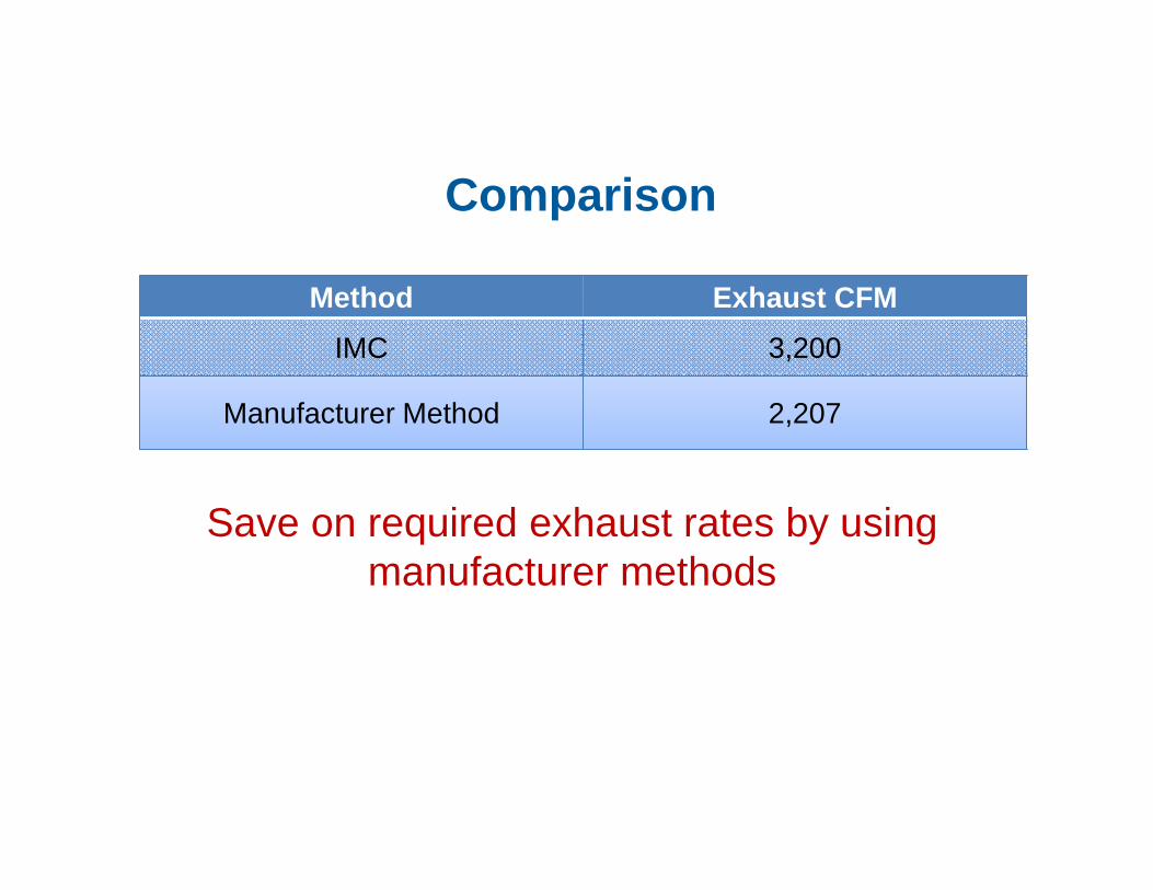
Method Exhaust CFM
IMC 3,200
Manufacturer Method 2,207
Save on required exhaust rates by using manufacturer methods
15
Comparison

16
Kitchen Control Technology
16
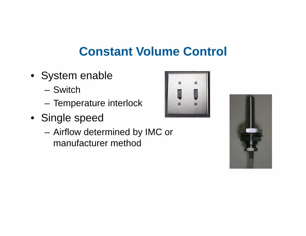
Constant Volume Control
• System enable– Switch– Temperature interlock
• Single speed – Airflow determined by IMC or
manufacturer method
17

Two Speed Systems
• Poor man’s demand control• High cost two speed motor• Manual control required• Over/Under ventilation
18

19
Demand Control Ventilation
• Provide the correct level of ventilation for the actual cooking load
• Modulate exhaust fan(s) and supply fan(s)
19

20
507.1 General. Commercial kitchen exhaust hoods shall comply with the requirements of this section. Hoods shall be type 1 or type 2 and shall be designed to capture and confine cooking vapors and residues.
Exceptions:1. Factory built commercial exhaust hoods which are tested2. Factory built commercial cooking recirculating systems3. Net exhaust volumes for hoods shall be permitted to be reduced during no load cooking conditions, where engineered or lis ted multi-speed or variable speed controls automatically operate the e xhaust system to maintain capture and removal of cooking effluents a s required by this section.
Changes Made to IMC 2003 (Current in 2010 )
IMC 2003 Edition
20

21
ASHRAE 90.1-2010 and Demand-Controlled Ventilation (DCV) Systems for KitchensASHRAE 90.1-2010 adopts new language regarding demand-based ventilation system(s) for kitchens. Section 6.5.7.1.4 states the following:“If a kitchen/dining facility has a total kitchen hood exhaust airflow rate greater than 5,000 cfm then it shall have one of the following:• At least 50% of all replacement air is transfer air that would otherwise be
exhausted. In most applications, the transfer air would be from a rooftop unit in an adjacent dining area.
• Demand ventilation system(s) capable of at least 50% reduction in exhaust and replacement air system airflow rates, including the controls necessary to modulate airflow in response to appliance operation.”
ASHRAE 90.1

ASHRAE 189.1
Standard for the design of high-performance green buildings• Section 7.4.3.7 – Variable Speed Fan Control
– In addition to the requirements in [ASHRAE] Standard 90.1, commercial kitchen type I and type II hoods shall have variable speed control for exhaust and make-up air fans to reduce hood airflow rates at least 50% during those times when cooking is not occurring…
• Not all manufacturers meet this requirement!
22

• 8.2 airflow‒ 8.2.1 air velocity
‒ 8.2.1.1 The air velocity through any duct shall be not less than 152.4 m/min (500 ft / min)
NFPA 96 – Grease Duct
23
NFPA 96 2008 Edition

24
ASHRAE ResearchTest Results – Duct Velocity
0.0
0.2
0.4
0.6
0.8
1.0
1.2
1.4
1.6
1.8
Dep
ositi
on F
lux,
µg/
ft²/m
in.
500 1000 1500 2000
Mean Duct Velocity, fpm
BottomSidesTop

• Temperature Based
• Temperature and Optics based
Variable Volume Systems
25

Variable Volume Options
• Temperature Based– Temp Sensors monitor heat– High Heat Applications
• Optics Based– Temp Sensors– Optic Sensors– Low Heat/High Steam Applications
26
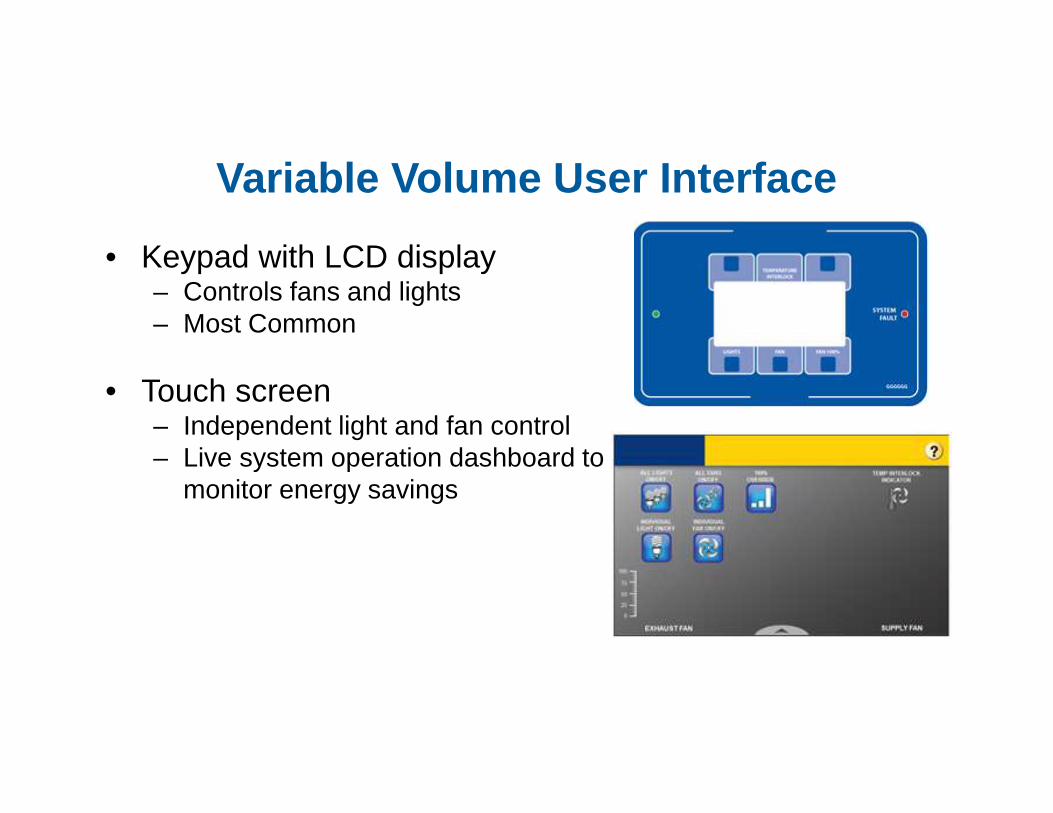
Variable Volume User Interface
• Keypad with LCD display– Controls fans and lights– Most Common
• Touch screen– Independent light and fan control– Live system operation dashboard to
monitor energy savings
27

Variable Volume and BMS
• Building management system interfacing
– LONworks
– BACnet MSTP
– BACnet IP
– Modbus
28

Variable Volume with EC Motors (ECMs)
• EC motors are compatible with the VAV system– Eliminates the need for a variable
frequency drive
– Provides additional electrical motor energy savings of 20-70%
– Eliminates belt maintenance
29

• Proportional tracking – Based on the weighted average speeds of the
exhaust fans– Issues
• Forward curve vs. backward incline wheels on exhaust and supply fans
• Direct gas make-up air
Supply Fan Control
33

Supply Fan Control
• Static pressure– Based on building static
pressure between the kitchen and dining room (adjacent space)
– Based on building static pressure between the kitchen and the outside
34

In our world of automation, kitchen ventilation systems are operating in the
dark ages
“Would you buy a car without a throttle?”
“Would you buy a house without a thermostat?”
35

DCV Benefits
36

37
Variable Volume Systems
• Monitors cooking activity and matches airflow to the cooking load

Energy Savings
• Increases overall hood efficiency by up to 20-50%
• Fan energy savings:
– 50% speed reduction = 88% savings
• Conditioned air savings: $1-$3/cfm per year
• Payback: 1-3 years depending on system
38

Savings - Example
39
Airflow 3,000 CFM
Operating 15 hours per day
Cost of conditioning $3/cfm per year
40% Reduction in airflow 1,200 cfmGenerates conditioned (H&C) air savings of $2,250 per year
Benefits
• Reduced electrical costs– Exhaust and supply fan motors
• Reduced heating and cooling costs– The majority of the energy saving is in the conditioned air
• Low fan maintenance
• Prolonged equipment life– VFD soft start
• Enhanced employee comfort– Reduced fan noise
40

Benefits
• Serves as IMC 2006 section 507.2.1.1 compliant device– Hood and appliance interlock
• Potential to contribute toward LEED credits– Innovation and design– Optimize energy performance
• Many states offer rebates to owners for purchasing and installing variable volume systems
41

Ideal DCV Applications
• Over 12 operating hours per day
• Hoods over 8 feet long
• Variable cooking loads throughout day
• Areas with high gas and/or electric rates
42

43
Other Energy Saving Options
44
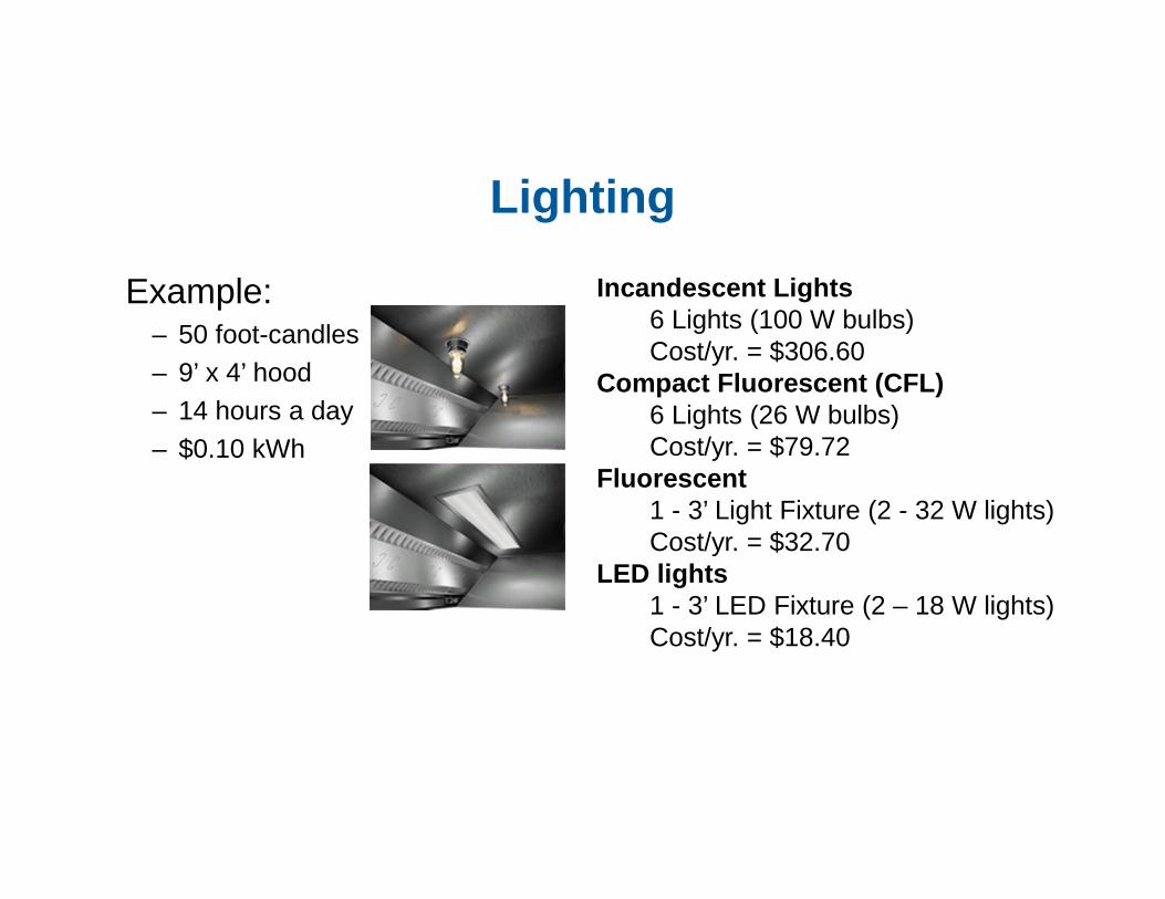
Lighting
Example: – 50 foot-candles – 9’ x 4’ hood – 14 hours a day – $0.10 kWh
Incandescent Lights6 Lights (100 W bulbs)Cost/yr. = $306.60
Compact Fluorescent (CFL)6 Lights (26 W bulbs)Cost/yr. = $79.72
Fluorescent 1 - 3’ Light Fixture (2 - 32 W lights)Cost/yr. = $32.70
LED lights1 - 3’ LED Fixture (2 – 18 W lights)Cost/yr. = $18.40

Design Considerations• Attention must be given to all building sources of outside
air– Dining room RTU (economizers)– Kitchen make-up air
• Minimum airflow requirements for gas fired make-up air and cooling coils – Furnace turn-down (temperature rise)
• Independent fan for each hood– Allows for increased savings
• Side skirts– Allows for slightly lower airflows
45

Design Considerations
• Supply lower velocity make-up air from multiple sources– When the supply limit is reached on the hood supply
plenum, add perforated ceiling diffusers for the remainder
– Use ASP/Perimeter supply on three sides of hood– Use face supply with perforated ceiling diffusers– Use back supply/rear discharge with face supply hood
46

Thank you for your time.
Questions?
47
48
The mission of Greenheck is to be the market leader in the development, manufacture and worldwide sale of quality air
moving and control equipment with total commitment to customer service.