Embed Size (px)
Citation preview

ASHES PHASE 3, SYMPHONY KITCHENS BARNSLEY
RIBA Stage 2 Report November 2019 Rev 0
Upperbank House, Stoneythorpe,
Leeds, LS18 4BN
United Kingdom W: silcockleedham.co.uk
T: +44 (0)113 393 3310

Silcock Leedham Consulting Engineers Ltd Feasibility Stage Report
11347: Ashes Phase 3, Symphony Kitchens Page 2 Silcock Leedham Consulting Engineers Ltd W: silcockleedham.co.uk T: +44 (0)113 393 3310
Table of Contents
1. Introduction .......................................................................................................................................... 4
1.1. Introduction................................................................................................................................... 4
1.2. Environmental Strategy – Design Approach ................................................................................. 4
2. Preambles ............................................................................................................................................. 5
3. Scope of Works ..................................................................................................................................... 6
4. External Liaison ..................................................................................................................................... 6
4.1. Cold Water Services ...................................................................................................................... 6
4.2. Natural Gas .................................................................................................................................... 6
4.3. Electricity ....................................................................................................................................... 7
4.4. Drainage ........................................................................................................................................ 7
4.5. Telecoms ....................................................................................................................................... 7
4.6. Unidentified services ..................................................................................................................... 7
5. Client Liaison (Briefing, Handover, Surveys)......................................................................................... 8
5.1. Client Brief ..................................................................................................................................... 8
5.2. Handover Documentation and Surveys ........................................................................................ 8
5.3. Soft Landings ................................................................................................................................. 8
6. Team Liaison (Builders Work, Spatial Co-ordination, Energy Targeting) ........................................... 10
6.1. Energy and Sustainability ............................................................................................................ 10
6.2. Preliminary Part L2a Calculation ................................................................................................. 10
6.3. BREEAM ....................................................................................................................................... 11
6.4. Building Orientation and Façade Design ..................................................................................... 11
6.5. Envelope Design .......................................................................................................................... 12
6.6. Design Criteria ............................................................................................................................. 13
7. Selection of Plant and Specialist Designers ........................................................................................ 15
7.1. Mechanical Plant ......................................................................................................................... 15
7.2. Electrical Plant ............................................................................................................................. 15
7.3. Nominated Contractors ............................................................................................................... 15
8. Mechanical Design .............................................................................................................................. 16
8.1. Heating & Cooling Systems ......................................................................................................... 16
8.1.1. Warehouse & Production ........................................................................................................ 16
8.1.2. Office & Pod Accommodation ................................................................................................. 17
8.1.3. Maintenance Workshops ........................................................................................................ 17
8.2. Ventilation Systems ..................................................................................................................... 17
8.3. Domestic Water Services ............................................................................................................ 18
Boosted Cold Water Service .................................................................................................................. 18
Domestic Hot Water Service ................................................................................................................. 18
8.4. Automatic Controls ..................................................................................................................... 19
8.5. Fire Fighting ................................................................................................................................ 19
8.6. Public Health ............................................................................................................................... 19
9. Electrical Design ................................................................................................................................. 21
9.1. Existing Incoming Electrical Engineering Services ...................................................................... 21
9.2. Electrical Infrastructure / LV Distribution ................................................................................... 21
9.3. General Power ............................................................................................................................ 21
9.4. Earthing and Bonding .................................................................................................................. 22
9.5. General Lighting and Emergency Lighting .................................................................................. 22
9.6. Lighting Controls Strategies ........................................................................................................ 23
9.7. Emergency Lighting ..................................................................................................................... 23
9.8. External Lighting ......................................................................................................................... 23
9.9. Induction Loops........................................................................................................................... 23
9.10. Fire Alarms .............................................................................................................................. 23
9.11. Security .................................................................................................................................... 23
9.12. Disabled Alarm Systems .......................................................................................................... 24
9.13. Data/Comms Installations ....................................................................................................... 24
9.14. Lightning Protection ................................................................................................................ 24
10. Commissioning and Maintenance .................................................................................................. 25
10.1. Commissioning ........................................................................................................................ 25
11. Deliverables (Drawings, Specifications, Reports) ........................................................................... 26
12. Appendix A – Existing Utility Records ............................................................................................. 27
13. Appendix B – MEP Sketch Proposals .............................................................................................. 28
14. Appendix C – Domestic Water Load Assessment ........................................................................... 29

Silcock Leedham Consulting Engineers Ltd Feasibility Stage Report
11347: Ashes Phase 3, Symphony Kitchens Page 3 Silcock Leedham Consulting Engineers Ltd W: silcockleedham.co.uk T: +44 (0)113 393 3310
Amendment Record Sheet
Revision Description Date Approved
0
RIBA Stage 2 issue to client & design team
25.11.19
CT

Silcock Leedham Consulting Engineers Ltd Feasibility Stage Report
11347: Ashes Phase 3, Symphony Kitchens Page 4 Silcock Leedham Consulting Engineers Ltd W: silcockleedham.co.uk T: +44 (0)113 393 3310
1. Introduction
1.1. Introduction
This section of the feasibility report aims to outline the principle design proposals and considerations relating to the Building Services and Environmental Control Strategies for the Ashes Phase 3 Project in Barnsley on behalf of Symphony Kitchens and intends to provide further detail on the relevant design proposals given to date. Aim of this Report This report has been prepared at RIBA Stage 0-2, which is generally defined as Strategic Definition, Preparation and Briefing/concept Stage, and provides initial detail relating to the Building Services and Environmental Control Strategies to date. The primary purpose of this report is to help achieve the following;
- Identification of the key requirements and constraints on the development, along with outline M&E principles to assist development of the project cost plan with an appropriate level of assurance to allow the Client team to appraise the viability and procurement
- To assist both the client and design teams to explore and understand the measures that need to be incorporated within the design of the Ashes Phase 3 with an aspiration to achieve a low energy building with a good Energy Performance Certificate (EPC) rating and ideally a corresponding Display Energy Certificate
It is proposed that the information contained within this report, if approved, shall support the Project Brief and provide a platform for the basis of the Design drawings and specifications. This report provides an overview of our understanding and has been structured for comment or feedback.
1.2. Environmental Strategy – Design Approach
This section summarises our environmental services principles for Ashes Phase 3, Barnsley on behalf of Symphony Kitchens. Our proposals align with the requirements in the Proposed Design Brief received to date and will be further developed to incorporate the feedback from further Client Engagement Meetings. New-build The intention is to minimise energy consumption by using passive design features – for example, building orientation, fabric thermal performance, low air permeability, optimising the glazing design to maximise daylighting while avoiding excessive solar gains, and using natural ventilation wherever possible. Engineered systems All plant, controls and equipment will be selected to deliver the highest seasonal operating efficiencies, which will help minimise carbon emissions and energy consumption. By adopting this approach and passive design measures, we aim to comply with Part L2A Building Regulations without the need to introduce renewable or low / zero-carbon energy systems (an assessment of which will be
developed during the next stage of design development). We will also design the environmental control systems so they can be operated easily by end users. Systems will be designed to reduce maintenance requirements, minimise running costs and maximise value for money for the client. The fundamental design approach is to follow the carbon roadmap as follows: Lean - Minimise consumption and waste - Reducing running costs - Keeping it simple - Passive building design Clean - Use energy efficiently - Recover energy wherever possible - Minimise emissions - Use of natural daylight Green - Minimise bolt-on technologies - Integrate only where necessary

Silcock Leedham Consulting Engineers Ltd Feasibility Stage Report
11347: Ashes Phase 3, Symphony Kitchens Page 5 Silcock Leedham Consulting Engineers Ltd W: silcockleedham.co.uk T: +44 (0)113 393 3310
2. Preambles
All equipment, materials and workmanship shall meet the requirements of, but not be limited to the following documents and standards unless otherwise indicated in this report: a) Conditions of Contract b) Other Standards:-
o Guides to Good Practice as published by the Chartered Institution of Building Services Engineers. (CIBSE)
o The Building Regulations.
o Room data sheets.
o BCGA guides (British Compressed gases association)
o Latest edition of British Standard Specifications and British Standard Codes of Practice (current
at date of tender), and European Norms.
o Gas Regulations.
o Water Regulations.
o The Local Authority Environmental Health Officer's requirements.
o Building Control Officer Requirements.
o Planning requirements.
o The Local Fire Officer's requirements.
o The Health and Safety at Work Inspectorate's requirements.
o BS 7671: Requirements for Electrical Installations.
o IET Wiring Regulations
o Building and Engineering Services Association (Formerly HVCA) Ductwork Specification Standards DW 144, 145 and 172
o CIBSE Commissioning Codes and BSRIA Commissioning Guides
o All other standards specifically noted within the Technical Sections of this specification.
o BSEN 12056: 2000 Parts 1-5 Gravity Drainage Systems Inside Building.
o BS 8000 – Part 13: Code of Practice for Above Ground Drainage and Sanitary Appliances. o Construction (Design and Management) Regulations
o Clean Air Act.
o Disability Discrimination Act (DDA). All water systems in the building are to be designed in accordance with the measures outlined in the Health and Safety Executive’s “Legionnaires’ disease – The control of legionella bacteria in water systems”. Approved code of practice and guidance, and where relevant, other industry/sector best practice guidance.

Silcock Leedham Consulting Engineers Ltd Feasibility Stage Report
11347: Ashes Phase 3, Symphony Kitchens Page 6 Silcock Leedham Consulting Engineers Ltd W: silcockleedham.co.uk T: +44 (0)113 393 3310
3. Scope of Works
The scope of the Mechanical and Electrical services works to be included for as part of this project includes the design, supply install, testing and commissioning the following;
• The schematic design and performance specifications of all mechanical and electrical services and systems
• Extension of incoming mains water supplies from the designated connection point
• LPHW heating systems
• Domestic hot & cold water services
• Mechanical ventilation systems
• Above ground drainage installation (below ground drainage by others)
• Thermal insulation of pipe and duct services
• VRF Heating and Cooling Installations
• Localised DX cooling
• Specialist Server Room Cooling
• BMS and automatic controls systems (Performance Specifications)
• Extension of existing HV network to new site
• Complete installation of LV infrastructure from supply side of HV switchgear to distribution boards.
• Lighting installation within office and ancillary areas
• Fire alarm installation throughout
• Security system including CCTV, burglar alarm and access control throughout
• Containment and supporting systems for all services including client’s DATA/Comms network
• Disabled toilet alarms
• All supporting infrastructure for all phased works
• Services identification
• Builderswork
• Contractors own site working drawings
• O&M manuals
• As fitted drawings
• Testing and commissioning
• Demonstration to Client
4. External Liaison
Existing Utility Services providers have been consulted as part of the proposed works, and a sub-tronic and ground penetrating radar survey may be required if there are any concerns of potential risks, but we understand from discussions with the client that the site is already mainly clear as was left prepared for this development when original developing the surrounding area. Below is a summary of the services located within the vicinity of the site during the survey, along with a brief summary of the proposed actions for removal, retention, relocation or other remedial works in order to facilitate the new development.
4.1. Cold Water Services
At the time of issuing this report we are still awaiting receipt of the existing utility records from Yorkshire Water. However, from discussions with the client and review of previous design drawings for the Phase 1 development on the adjacent plot, it is understood that there is a nearby water main within close proximity of the main access road and it is intended that this main will be utilised to serve the new development. A preliminary load assessment has been carried out for domestic water purposes only (no process) and this assessment is suggesting a peak cold water demand of 3L/s is required to serve the development.
4.2. Natural Gas
Consideration has been given to the provision of a new gas supply to site to support the proposed heating strategy discussed within this report. Existing utility records indicate a LP gas supply is already in close proximity to the site boundary as per below extract.

Silcock Leedham Consulting Engineers Ltd Feasibility Stage Report
11347: Ashes Phase 3, Symphony Kitchens Page 7 Silcock Leedham Consulting Engineers Ltd W: silcockleedham.co.uk T: +44 (0)113 393 3310
However, we understand that the client will be procuring a dedicated Biomass boiler that will primarily heat the building and therefore no gas supply will be required to serve the development, and therefore has not been allowed for at this stage.
4.3. Electricity
An existing 11kV HV supply network exists within the grounds. An application to NPG will be made to adapt the network for connection into the new HV switchgear that will supply a new HV/LV transformer and LV switchgear. This will provide power for the warehouse, production area, offices, workshop and boiler house.
4.4. Drainage
We are still awaiting receipt of the existing utility records from Yorkshire Water, however, from existing design information from the Phase 1 development we understand that provision has been made for this site in previous infrastructure works along the estate road. The design of the new drainage system will be developed in more detail within the Civil and Structural Engineers report.
4.5. Telecoms
We are still awaiting the receipt of the existing BT infrastructure records however due to the proximity of the existing site we do not anticipate a new BT connection introducing major issues. Virgin Media do not have infrastructure in the nearby area and so connection to their services is not an option.
4.6. Unidentified services
In most survey instances, there are a number of ‘unidentified services’ located within the ground. However, from discussions with the client’s team we understand the proposed site is clear of unknown services below the ground as a level of development was carried out when the overall masterplan of the estate was carried out during previous phases. Therefore, it is deemed to be a low risk that any unidentified services would be found within the site demise. As the level of unidentified services on this site is low, the associated risk is not considered significant.

Silcock Leedham Consulting Engineers Ltd Feasibility Stage Report
11347: Ashes Phase 3, Symphony Kitchens Page 8 Silcock Leedham Consulting Engineers Ltd W: silcockleedham.co.uk T: +44 (0)113 393 3310
5. Client Liaison (Briefing, Handover, Surveys)
5.1. Client Brief
The project generally consists of a circa 300,000ft² warehouse/production facility plus associated office accommodation as shown on the architect general arrangement drawings. Due to previous experiences the client wishes to be very prescriptive over the type and make of services that are to be provided and also requires a great level of flexibility in the design to give them options even into the post contract stage of the project to facilitate their fit out. Following a briefing meeting with the client on the 30th October 2019, the following key points are to be adhered to and agreed to be within our scope of works:
1. Heating a. Symphony to provide biomass boiler. SLCE to allow for PHX and secondary systems into the
building (Pipework, emitters etc) b. Symphony currently have unit heats and de-stratification fans within their Phase 1 development,
but are happy for SLCE to explore an alternative such as centralised AHU with high velocity nozzle system though.
2. Compressed air a. Not within SLCE scope; is to be part of clients specialist fit out post contract.
3. Lighting a. Office lighting to be included in SLCE scope of works.
i. No lux level controls to be provided. Just presence and absence detection with potential daylight linking required near windows to comply with BREEAM.
b. Warehouse & Production – as final use of these spaces won’t be confirmed until potentially post contract, and as the light fitting type and design will differ subject to this final use, then it was agreed that no general lighting would be provided in these spaces. However, a general provision of a lighting busbar system is to be installed so fittings can be installed at a later date.
c. External lighting is currently Holophane. Client would like to keep with the same manufacturer for continuity on the new site.
4. Hot & Cold Water a. Primary cold water main to be distributed through the main warehouse spaces to serve each
office pod and main office block. b. Localised hot water heaters to each area to be provided.
i. Currently proposed to be centralised calorifiers to each block/zone, rather than local electric water heaters.
c. Electrical back up required to each hot water for when boiler is not in operation for maintenance.
5. Sprinklers/fire fighting a. Existing mains infrastructure hydrant to be extended to cover new site. b. Roof protection sprinklers to be provided as part of SLCE’s scope, with capped off supplies to
facilitate in-rack fit out post completion if required. c. LPC standards to be complied with. d. FM200 to be included for office server room.
6. Power a. Central HV transformer and LV panel to be provided. b. As per lighting, warehouse and production spaces are to be provided with an infrastructure of
busbar to facilitate fit out of machinery as client fit out. i. 2000A in production (along GL-H)
ii. 1000A in warehouse (along GL-C)
c. Office to be supplied from production or warehouse power supply. No separate supply. d. Offices to have raised floor with underfloor busbar and floor boxes.
7. CCTV a. No CCTV to be provided internally. Just modifications to externals to be included.
8. Access control a. To be included and Symphony to confirm which doors required to be controlled as scheme
develops. b. Equipment that is mains powered (no batteries) to be provided.
9. General a. ‘Race track’ arrangement for base build M&E services to be considered and allow for space for
client fit out/process services to be distributed on the same rack. b. Plant deck to be developed on roof of main office block to site office equipment and also
potential AHUs for the warehouse/production spaces. c. Localised plant deck on top of each office pod required for services for that area/zone. d. Symphony happy for AC condensers to be located within the main building envelope, rather than
have an external compound. e. Client preferred manufacturers
i. Schneider LV panels and DBs ii. MK switches/sockets
iii. Busbar – as existing (to be confirmed) iv. AC – Toshiba or Mitsubishi
f. Kitchen is to be fit out by Symphony. Capped off supplies only to be provided. 10. M&E contractor appointment
a. Was generally agreed that we would pre-qualify proposed M&E contractors and provide a list of preferred ones to the Main contractors for them to obtain tenders from as part of main contract.
5.2. Handover Documentation and Surveys
Some limited as built information (Drawings and tender specifications) have been provided with regards the adjacent phase 1 development, and a non-intrusive site survey has been undertaken on the existing facility to ascertain a better understanding of the current services provision and requirements.
5.3. Soft Landings
SLCE are committed to involvement in a soft landings approach to all projects to assist in the inception, delivery, and post occupancy operation of the development. Soft Landings is a ‘cradle-to-operation’ project process which enables designers and constructors to focus more on operational performance outcomes. The approach helps project teams to deliver buildings that achieve their energy and environmental performance ambitions, while also focusing more on meeting the needs of occupants. Soft Landings requires clients and their design teams to make more use of performance feedback, from pre and post-occupancy building evaluations, to better inform client requirements and design briefs. Soft Landings also provides a mechanism for designers and constructors to remain involved with their buildings beyond practical completion, which doesn’t happen on standard building projects. The objective is not to throw more effort at resolving defects, but to spend quality time assisting the client and occupiers during the first months of operation and beyond. The professional aftercare element of Soft Landings is about fine-tuning and de-bugging systems, and ensuring occupiers understand their working environment better. Soft Landings does this by being a process that brings everyone on a project together to focus more on the desired operational outcomes. There are additional steps during briefing, design and delivery to enable this. Soft Landings also provides a platform for integrating the many disparate mechanisms that aim to produce better
Silcock Leedham Consulting Engineers Ltd Feasibility Stage Report
11347: Ashes Phase 3, Symphony Kitchens Page 9 Silcock Leedham Consulting Engineers Ltd W: silcockleedham.co.uk T: +44 (0)113 393 3310
buildings, such as energy performance certification, environmental labelling, building performance evaluation, POE, occupant satisfaction surveys, and both quantitative and qualitative (health and wellbeing) building performance metrics. In essence, Soft Landings involves:
• Achieving greater clarity at the inception and briefing stages about client needs and required outcomes
• Placing greater emphasis on building readiness, by the designer and constructor having greater involvement during the pre-handover and commissioning stages.
• A resident Soft Landings team located on site during the users' initial settling-in period
• Remaining involved after occupation, during and beyond the defects liability period to resolve outstanding issues
Soft Landings requires designers and constructors to spend more time on constructive dialogue with the client, and in setting expectations and performance targets on energy and end-user satisfaction. Everybody involved will benefit from the lessons learned from occupant satisfaction surveys and energy monitoring. The work steps in Soft Landings enable operators and users to spend more time on understanding interfaces and systems before they occupy the building. The designers and key contractors are tuned to understand and support the end-users in the critical early period of occupation.

Silcock Leedham Consulting Engineers Ltd Feasibility Stage Report
11347: Ashes Phase 3, Symphony Kitchens Page 10 Silcock Leedham Consulting Engineers Ltd W: silcockleedham.co.uk T: +44 (0)113 393 3310
6. Team Liaison (Builders Work, Spatial Co-ordination, Energy Targeting)
6.1. Energy and Sustainability
The energy strategy will be aligned to the objectives and developed to meet the performance targets of the Barnsley Local Plan. The current Local Plan, adopted January 2019, sets out the key elements for the planning framework for Barnsley to help achieve the Council’s vision towards 2033. In addressing Climate Change, the Local Plan requires development to follow the energy hierarchy; minimising the demand for energy using passive measures and energy-efficient services prior to incorporating viable low and zero carbon technology. The Council have targeted that 20% of all energy consumed within the borough are derived from renewable sources by 2025. Broader sustainability issues will be considered through a BREEAM assessment where a minimum rating of ‘Very Good’ must be achieved. One of the key criteria which will inform the design approach from the very earliest stages is to provide stable environmental conditions that ensure suitable operating conditions and promote occupant comfort. This will be achieved using engineering solutions that are intrinsically sustainable and energy efficient. In order to reduce CO2 emissions, it is paramount that the energy demand of the building is minimised through robust envelope design and the proficient use of services prior to the use of low carbon and renewable energy technologies. Minimising energy demand through adherence to the established Energy Hierarchy is positively reflected in the derivation of the BREEAM Ene01 credit score. This scheme will offer considerable benefit to building users in taking a sustainable approach to heating, ventilation, cooling and lighting design, including:
• high air quality levels maintained through the appropriate provision of filtered fresh air;
• natural light to reduce tiredness and promote concentration;
• artificial lighting solutions that create a sense of space and wellbeing;
• calm, quiet rooms without undue reverberation;
• comfortable, stable temperatures throughout the year;
• exemplary performance underpinned by passive design rather than retrospective technologies, resulting in low energy consumption and on-going running costs; and
• above all else, an environment which surpasses design guidelines and statutory requirements. The principle regulated energy demands for the building are for internal lighting, space heating and domestic hot water generation. In addressing this, our key strategy is to introduce levels of insulation and air tightness that are well in excess of current Building Regulations and the provision of natural light. This in combination with the items listed below will to achieve a building that is intrinsically low energy.
• Low thermal U-values; equal or better than the current Part L Notional building standards.
• An air-tight building envelope with target air permeability <3 m3/h.m2 @ 50Pa.
• Well insulated heating and DHW distribution pipework.
• Variable speed pumping and two port control strategies for the heating systems.
• Heat recovery devices within mechanical ventilation systems to extract thermal energy from stale air.
• Ventilation control linked to air quality sensors to limit fan operation only to times when required.
• Rooflights accounting for approximately 10% of roof area.
• Glazing area and specification to maximise beneficial solar gain whilst mitigating the risk of overheating.
Wherever possible an exposed high mass structure will be used within office areas to assist in minimising internal temperature fluctuations. Suspended ceiling systems will generally only be provided to conceal M&E services items on primary service routes (i.e. circulation areas, corridors etc). Within the design, the following key control strategies will also be adopted to assist in reducing energy consumption further.
• Ventilation, heating, domestic water, artificial lighting and security systems will be zoned in order that they may respond to the varying usage requirements of the building.
• Heating generation, hot water circulation and mechanical ventilation will be limited to times when they are required.
• Automatic lighting control will be installed to limit the use of internal lighting to occupied periods via presence and absence detection. An override facility will be provided wherever necessary.
• All luminaires will be including integral photoelectric sensors to allow automatic dimming or switching when sufficient natural light is available. This feature will save energy and maintain the intensity and distribution of light within occupied spaces.
Energy reduction techniques follow a hierarchal order:
• Lean – Demand minimisation via building envelope performance;
• Clean – Efficient supply and building operation; and
• Green – Enhancement via viable LZC technology.
6.2. Preliminary Part L2a Calculation
A preliminary Part L2a compliance assessment has been carried out based upon the current Architectural design and system philosophies outlined in this report utilising a Government-approved, dynamic simulation modelling software package. At this early stage a number of system parameters have been assumed to enable the calculation to be completed. These assumptions are considered to be relatively conservative and meet the minimum requirements set out within the Non-domestic Building Services Compliance Guide. Calculation results show that in conjunction with proposed insulation levels and upper air permeability limit, the building must utilise mechanical and electrical services that offer high heat generation efficiencies and high luminaire efficacies, albeit not exceeding values typically expected for this type of development. Owing to the client’s preference to utilise a Biomass fuel source, predicted annual CO2 emissions are low. Results show that no further LZC technology is required to achieve compliance with Part L2a. However, any further reduction in energy demand and annual CO2 emissions will likely result in additional BREEAM credit if required and lower on-going running costs.
Silcock Leedham Consulting Engineers Ltd Feasibility Stage Report
11347: Ashes Phase 3, Symphony Kitchens Page 11 Silcock Leedham Consulting Engineers Ltd W: silcockleedham.co.uk T: +44 (0)113 393 3310
This preliminary compliance calculation demonstrates a ‘Pass’ based upon achieving a predicted Building CO2 Emissions Rate (BER) lower than the regulatory Target CO2 Emissions Rate (TER). Throughout the development of the scheme it is critical that the building model is updated at key design stages to ensure compliance at all key stages of the project. At each point, compliance must be assessed against both the Building Regulations requirements and also related credits within the BREEAM assessment. For the purposes of the preliminary Part L2a assessment we have made the following assumptions at this stage:
- Production/warehouse – B2-B7 Industrial process/storage. - Offices etc. – B1 Office - Biomass boiler efficiency – 75% - Heating via air distribution to production/warehouse – SFP 1.9W/l/s, HR75%, - Office VRF SEER 4.0, SCOP 4.0 - Supply & extract mech vent to all occupied office areas – SFP 1.9W/l/s, HR75%, CO2 speed control - Indirect calorifier for office/warehouse DHW – 500l store, 200m secondary circulation in offices, 0.95
distribution efficiency to account for primary losses between boiler room PHX and calorifier. - Luminaire efficacies – warehouse/offices 100lm/W, circulation, WCs, stores etc. 80 llm/W. - Daylight dimming in all daylit spaces. Occupant control in all occupied spaces.
6.3. BREEAM
The development must achieve a minimum 2018 BREEAM rating of ‘Very Good’. Using the BREEAM Assessment Scoring and Reporting Tool (v2.3), the current Part L results shows an EPR of 0.318 to be achieved, corresponding to 3 credits against issue ENE01.
6.4. Building Orientation and Façade Design
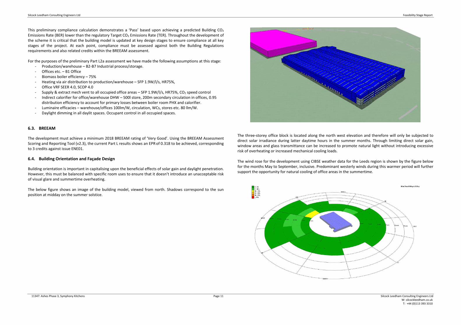
Building orientation is important in capitalising upon the beneficial effects of solar gain and daylight penetration. However, this must be balanced with specific room uses to ensure that it doesn’t introduce an unacceptable risk of visual glare and summertime overheating. The below figure shows an image of the building model, viewed from north. Shadows correspond to the sun position at midday on the summer solstice.
The three-storey office block is located along the north west elevation and therefore will only be subjected to direct solar irradiance during latter daytime hours in the summer months. Through limiting direct solar gain, window areas and glass transmittance can be increased to promote natural light without introducing excessive risk of overheating or increased mechanical cooling loads. The wind rose for the development using CIBSE weather data for the Leeds region is shown by the figure below for the months May to September, inclusive. Predominant westerly winds during this warmer period will further support the opportunity for natural cooling of office areas in the summertime.

Silcock Leedham Consulting Engineers Ltd Feasibility Stage Report
11347: Ashes Phase 3, Symphony Kitchens Page 12 Silcock Leedham Consulting Engineers Ltd W: silcockleedham.co.uk T: +44 (0)113 393 3310
6.5. Envelope Design
To achieve an inherently low energy building in line with client aspiration and regulatory requirements, the performance of the thermal building envelope will be far better than the limiting values stipulated within Building Regulations Part L2a. The following table sets out the proposed initial specification for the building envelope.
Element Criteria / Value Notes
Ground floor – process/warehouse U-value 0.06 W/m2.K Calculated for P/A 0.02.
Ground floor – office, pods etc. U-value 0.22 W/m2.K Insulated to achieve U-value.
External walls U-value 0.26 W/m2.K Built-up metal cladding.
Internal walls - warehouse to office block and pods
U-value 0.35 W/m2.K Assumed between areas with differing heating profiles.
Roof U-value 0.18 W/m2.K Built-up metal cladding.
Windows/curtain wall U-value 1.50 W/m2.K, g-value 0.40, vlt0.70
Solar control assumed; higher values may be permissible.
Rooflights U-value 1.60 W/m2.K, g-value 0.67, vlt0.61
Kingspan KS1000DLTR clear product assumed.
Personnel doors U-value 2.20 W/m2.K Powder coated aluminium doors.
Vehicle dock doors U-value 1.50 W/m2.K Insulated PVC sectional doors.
Air permeability <3 m3/m2.hour @ 50Pa

Silcock Leedham Consulting Engineers Ltd Feasibility Stage Report
11347: Ashes Phase 3, Symphony Kitchens Page 13 Silcock Leedham Consulting Engineers Ltd W: silcockleedham.co.uk T: +44 (0)113 393 3310
6.6. Design Criteria
The following indicates the outline design principles that are proposed for the proposed development. The principles outlined are attributed to the proposed Ashes Phase 3, Barnsley on behalf of Symphony Kitchens. The information produced has been developed in conjunction with the design team and building users, and has been provided to meet the initial sustainability principles set out in this report. Internal Design Conditions: General Warehouse & Production Spaces Summer internal temperature Uncontrolled Winter internal temperature Min. 20°C Fresh air ventilation 10 l/s/p - Mechanical ventilation c/w high velocity jet nozzles Noise criteria NR40 (refer to Acoustic specification) Heating/Cooling Warm Air AHU General Office Areas & Entrance Summer internal temperature Max 24°C Winter internal temperature Min. 21°C Fresh air ventilation 10 l/s/p - Mechanical ventilation Noise criteria NR35 (refer to Acoustic specification) Heating/Cooling VRF/VRV Toilets Summer internal temperature Uncontrolled Winter internal temperature Min. 18°C Fresh air ventilation 6 ac/hr - Mechanical ventilation Noise criteria NR35 (refer to Acoustic specification) Heating/Cooling Radiators / Ventilation Showers/Changing Rooms Summer internal temperature Uncontrolled Winter internal temperature Min. 18°C Fresh air ventilation 10 ac/hr - Mechanical ventilation Noise criteria NR35 (refer to Acoustic specification) Heating/Cooling Radiators / Ventilation Corridors Summer internal temperature Uncontrolled Winter internal temperature Min. 18°C Fresh air ventilation Transient Noise criteria NR40 (refer to Acoustic specification) Heating/Cooling Radiators
Server Room Summer internal temperature Uncontrolled Winter internal temperature Max 24°C (RH 40-55%) Fresh air ventilation Min. 21°C (RH 40-55%) Noise criteria NR40 (refer to Acoustic specification) Heating/Cooling DX Upflow/Downflow units (N+1) Equipment gain TBC by clients ICT specialist
Kitchens Summer internal temperature Uncontrolled Winter internal temperature Max 18°C (RH 40-55%) Fresh air ventilation 40 ac/hr - Negative pressurisation Noise criteria NR40 (refer to Acoustic specification) Heating/Cooling Radiators / Ventilation Equipment gain TBC by clients kitchen specialist
External Design Conditions The external design conditions stated in this are based on peak daytime conditions, as the occupancy of the new buildings are likely to normally occur during the daytime (office hours), we have maintained these design conditions:
Condition
Winter ambient (fabric load) -5oC
Winter ambient (AHU sizing) -8oC
Summer ambient temperature 28oC db, 21oC wb
Operating Conditions The operating conditions and temperatures for the building services systems have been developed based upon previous design experience and best practice guidance to ensure the effective and efficient operation of the systems as follows: Heating Low Pressure Hot Water – Provided by Clients Biomass boiler Flow temperature 80°C Return temperature 60°C CWS Storage 10°C
DHWS Storage 60°C (min) Internal Sensible Heat Gains Metabolic 90W (s) / 60W (l) person

Silcock Leedham Consulting Engineers Ltd Feasibility Stage Report
11347: Ashes Phase 3, Symphony Kitchens Page 14 Silcock Leedham Consulting Engineers Ltd W: silcockleedham.co.uk T: +44 (0)113 393 3310
Lighting 10 W/m2 Power 15 W/m2
Solar <35 W/m2
PC and fixed equipment gains
Typical values are provided in the schedule below (to be developed during the design of the project):
Item: Active (watts)
Passive (watts)
Standby (watts)
Generic (watts)
High spec CAD / Media workstation 225 105 5 165
Generic desktop computer 105 75 2 99
Staff laptop / tablet 35 5 1 26
LCD monitor / dock (for laptop) 20 5 1 12
Large display screen 200 n/a 4 200
Digital signage / IP-TV receiver 15 n/a 5 15
Data projector 250 n/a 5 200
Interactive whiteboard 2 n/a n/a 2
Visualiser 20 n/a 5 8
Network Printer 567 55 17 160
Local Printer 260 13 4 45
PDA / mobile phone 3 1 n/a 1
IP Telephone 7 5 2 4
Wireless Access Point 15 10 n/a 12
CCTV Camera 10 n/a n/a 10
Occupant equivalent 100 70 n/a 90
BIM and REVIT We understand there is no formal BEP that is to be adhered to as part of this project. We understand the architect and structural teams will be producing their drawings based on a revit model, which we can use to assist with the design, but the MEP package is to be undertaken in 2D CAD format.

Silcock Leedham Consulting Engineers Ltd Feasibility Stage Report
11347: Ashes Phase 3, Symphony Kitchens Page 15 Silcock Leedham Consulting Engineers Ltd W: silcockleedham.co.uk T: +44 (0)113 393 3310
7. Selection of Plant and Specialist Designers
Listed below are manufacturers for plant items and equipment to be specified for the project. Other manufacturers may be used, subject to approval by Silcock Leedham Consulting Engineers.
7.1. Mechanical Plant
Item Manufacturer
Pumps Grundfos, Wilo, Holden & Brook
Radiators Stelrad, Myson, Hudevad
Radiant/Trench Heating Zehnder, S&P coils
Air handling pant
Warehouse: Casaire, Jet Environmental Offices: Air Source, Nuaire, Barkell, Moducel
Supply/Extract Fans Nuaire or Vent-Axia
Attenuators Allaway, Caice
Grilles Waterloo, Gilberts
VAV Boxes Trox
DX comfort cooling/VRF Toshiba or Mitsubishi
HWS Plate heat exchangers Arbe, Alfa Laval UK-Plates, Rycroft
Electric water heaters Heatrae Sadia or Zip
Plant Support Systems Bigfoot
Valves Hattersley, Pegler, Crane
TRV’s Overntrop, Pegler, Hattersley
Fan Coil Units Toshiba or Mitsubishi
Pressurisation Units Holden & Brook, Pullen
Controls Trend IQ3 Control Systems
Dampers Actionaire
7.2. Electrical Plant
Item Manufacturer
LV Switchgear Schneider
Distribution Boards Schneider
LV Mains Cables BICC, Pirelli or AEI (BASEC Approved)
Fire Rated Cables Draka or Pirelli
Cable tray and Basket and trunking Legrand, Marshall Tufflex, MK, Mita, Tamlex.
Electrical Accessories MK
Automatic Lighting Controls EX-OR
Fire Alarm Gent Vigilon
Passenger Lifts Otis
Busbars Schneider Canalis
7.3. Nominated Contractors
As aforementioned in this report, the client has previously had a bad experience on their previous projects, which they do not wish to repeat. Therefore, to ensure adequate quality and workmanship is included within the project it has been agreed by the design team that the M&E and Sprinkler Contractors will be pre-qualified direct by the team, and then nominated to the main contractors as preferred contractors to engage with as part of the tendering process. The pre-qualification exercise is yet to be undertaken, but based on preliminary thoughts and discussions, the current list of potential contractors will include but not limited to:
• Halsall Mechanical & Electrical
• Imtech
• Pitts Wilson
• Elm Building Services
• G&H Building Services
• Alpine Fire (Fire Fighting & Sprinklers only)
Silcock Leedham Consulting Engineers Ltd Feasibility Stage Report
11347: Ashes Phase 3, Symphony Kitchens Page 16 Silcock Leedham Consulting Engineers Ltd W: silcockleedham.co.uk T: +44 (0)113 393 3310
8. Mechanical Design
8.1. Heating & Cooling Systems
8.1.1. Warehouse & Production
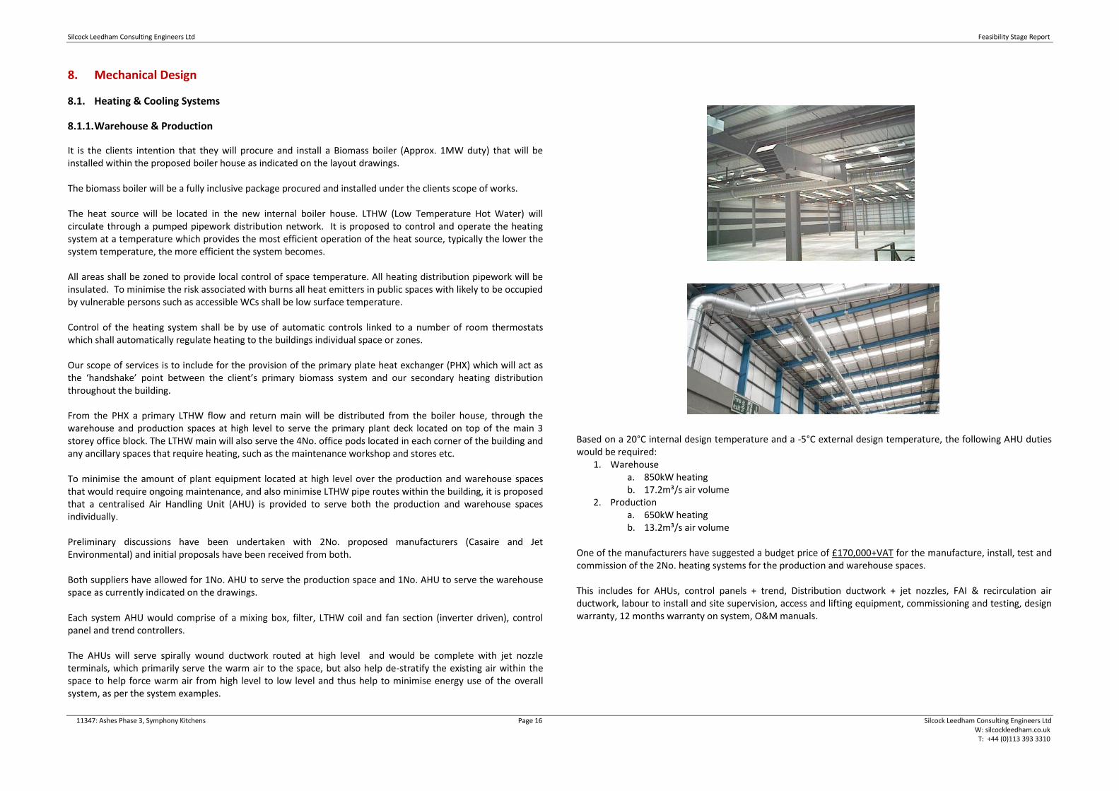
It is the clients intention that they will procure and install a Biomass boiler (Approx. 1MW duty) that will be installed within the proposed boiler house as indicated on the layout drawings. The biomass boiler will be a fully inclusive package procured and installed under the clients scope of works. The heat source will be located in the new internal boiler house. LTHW (Low Temperature Hot Water) will circulate through a pumped pipework distribution network. It is proposed to control and operate the heating system at a temperature which provides the most efficient operation of the heat source, typically the lower the system temperature, the more efficient the system becomes. All areas shall be zoned to provide local control of space temperature. All heating distribution pipework will be insulated. To minimise the risk associated with burns all heat emitters in public spaces with likely to be occupied by vulnerable persons such as accessible WCs shall be low surface temperature. Control of the heating system shall be by use of automatic controls linked to a number of room thermostats which shall automatically regulate heating to the buildings individual space or zones. Our scope of services is to include for the provision of the primary plate heat exchanger (PHX) which will act as the ‘handshake’ point between the client’s primary biomass system and our secondary heating distribution throughout the building. From the PHX a primary LTHW flow and return main will be distributed from the boiler house, through the warehouse and production spaces at high level to serve the primary plant deck located on top of the main 3 storey office block. The LTHW main will also serve the 4No. office pods located in each corner of the building and any ancillary spaces that require heating, such as the maintenance workshop and stores etc. To minimise the amount of plant equipment located at high level over the production and warehouse spaces that would require ongoing maintenance, and also minimise LTHW pipe routes within the building, it is proposed that a centralised Air Handling Unit (AHU) is provided to serve both the production and warehouse spaces individually. Preliminary discussions have been undertaken with 2No. proposed manufacturers (Casaire and Jet Environmental) and initial proposals have been received from both. Both suppliers have allowed for 1No. AHU to serve the production space and 1No. AHU to serve the warehouse space as currently indicated on the drawings. Each system AHU would comprise of a mixing box, filter, LTHW coil and fan section (inverter driven), control panel and trend controllers. The AHUs will serve spirally wound ductwork routed at high level and would be complete with jet nozzle terminals, which primarily serve the warm air to the space, but also help de-stratify the existing air within the space to help force warm air from high level to low level and thus help to minimise energy use of the overall system, as per the system examples.
Based on a 20°C internal design temperature and a -5°C external design temperature, the following AHU duties would be required:
1. Warehouse a. 850kW heating b. 17.2m³/s air volume
2. Production a. 650kW heating b. 13.2m³/s air volume
One of the manufacturers have suggested a budget price of £170,000+VAT for the manufacture, install, test and commission of the 2No. heating systems for the production and warehouse spaces. This includes for AHUs, control panels + trend, Distribution ductwork + jet nozzles, FAI & recirculation air ductwork, labour to install and site supervision, access and lifting equipment, commissioning and testing, design warranty, 12 months warranty on system, O&M manuals.

Silcock Leedham Consulting Engineers Ltd Feasibility Stage Report
11347: Ashes Phase 3, Symphony Kitchens Page 17 Silcock Leedham Consulting Engineers Ltd W: silcockleedham.co.uk T: +44 (0)113 393 3310
If the client would approve a lower internal design temperature of 16°C, then the following AHU duties would be required:
1. Warehouse a. 616kW heating b. 12.94m³/s air volume
2. Production a. 427kW heating b. 8.98m³/s air volume
As the total of both these AHUs is in excess of the proposed 1MW biomass boiler load on their own, then it may be that the client needs to increase the duty of their biomass provision or reduce the internal design temperature to suit. Please refer to Appendix B for sketch proposals for the location and route of the associated services.
8.1.2. Office & Pod Accommodation
Within the main office and pod accommodation it is proposed that the primary office areas are served by a VRF simultaneous heating and cooling system. This system generally consists of centralised heat pump which will be located on the roof of the inboard office accommodation and will reject heat into the overall warehouse and production spaces. The centralised VRF condenser will serve a number of internal terminal Fan Coil Unit (FCU) to provide heating or cooling within that room/zone such as the open plan office and meeting rooms via ceiling mounted grilles/diffusers.
For ancillary and ‘back of house’ areas such as toilets, corridors, kitchens, changing areas etc, it is proposed that the LTHW main served by the biomass is utilised to directly serve traditional LTHW radiators at low level.
8.1.3. Maintenance Workshops
Maintenance and workshop areas are to be heated by indirect Unit heaters complete with LTHW coil served from the primary LTHW main from the boiler house. Unit heaters will generally be located at high level in corners of the space to offset the heat losses of the space.
8.2. Ventilation Systems
The ventilation of the warehouse and production spaces will be via the AHUs discussed under section 8.1.1 of this report. For the office and pod accommodation there will be following ventilation systems required:
General Supply & Extract Systems It is currently proposed that there will be 2No. dedicated air handling units located on the main office roof deck incorporating heat recovery via thermal wheel or PHX section.
Each AHU will serve approximately half of the 3-storey office accommodation subject to final design and duty. The systems shall be ducted either via ductwork distributed through risers and ceiling voids to grilles/diffusers and where installed to the back of the heating/cooling fan coil units. The units shall be controlled on time schedule for the spaces and provide tempered fresh air. The AHU’s shall incorporate inverter driven supply and extract fans, filters, heating coils, heat exchangers, dampers, sensors, gauges and controls. The supply and extract ductwork shall be fully insulated both internally and externally suitable for the environment it is in. Volume control dampers shall be provided throughout the ductwork systems to enable balancing of the system. Fire dampers shall be provided where ductwork passes through fire compartments and shall be of the same fire rating as the construction it passes through.

Silcock Leedham Consulting Engineers Ltd Feasibility Stage Report
11347: Ashes Phase 3, Symphony Kitchens Page 18 Silcock Leedham Consulting Engineers Ltd W: silcockleedham.co.uk T: +44 (0)113 393 3310
Dedicated Kitchen Ventilation As discussed during our client briefing meeting, the extent of the kitchen fit out and the associated equipment to be installed is not yet fully known. However, at this stage it is envisaged that the kitchen area shall be provided with a dedicated extract fan unit which shall be used to ventilate the kitchen as and when required. The fan shall be sized to provide a minimum air change rate to the kitchen area. The fan shall be operated manually and shall be variable speed to cater for varying ventilation demand. WC Extract Systems Separate dedicated dirty extract system will be provided for the office toilet areas. This system will extract vitiated air from the WC accommodation. The ventilation systems shall discharge to atmosphere in discreet locations, where possible to the external main building envelope façade. Fans shall be automatically operated to switch on and off according to the use of individual WC accommodation. Local Heat Recovery Ventilation
The office pod accommodation is proposed to be installed with a local heat recovery unit (HRU) providing supply and extract air to the office and ancillary accommodation within these pods. The HRU will comprise filter, heat exchanger, heating coil, supply and extract fans and internal/external grilles. The unit shall be provided with standalone, self-contained controller, which will be enabled via the BMS installation. The units shall be controlled from a CO2 sensor.
8.3. Domestic Water Services
The domestic hot and cold water systems shall be designed to provide wholesome water at acceptable condition, flow, temperatures and pressure to all draw offs within the building. The design shall be fully in accordance with BS EN 806, BS 8558 (2015), HSE ACOP L8 and IPE design guidelines. The hot and cold water systems shall be complete with all necessary draining, venting, isolating valves, double check valves, strainers and pressure reducing valves, necessary to comply with the local water authority requirements, in addition to those required to commission and maintain the system. All hot and cold water pipework and fittings shall be thermally insulated. A complete vapour seal shall be made to cold water services pipework. Metal clad protection shall be provided to all pipework within plantroom areas up to 1.8 m. The hot and cold water services systems shall operate at the same static pressures (dynamic) to prevent fluctuations in water temperatures where thermostatic mixing valves are utilised. Mains Cold Water Service
It is proposed that a new mains cold water service is provided from a new Yorkshire Water meter located adjacent to the site. An initial assessment of the peak simultaneous demand has been undertaken, which indicate a total peak flow rate of approximately 3.0 l/s is required for the whole development, with applications to be made to Yorkshire Water for the new supply.
A new mains cold water service (MCWS) connection shall be taken from the Yorkshire Water main in the adjacent highway, extended from the site boundary and run across to enter the building in the main office block or warehouse/production space. All new buried mains are to be installed in a WRAS approved barrier type pipe from the point of new connection to point of entry to the building. The mains cold water supply shall distribute within warehouse/production space and serve a potable cold water storage tank located on the roof/plant deck of the main office block and pods. Each system will be complete with a dedicated pressure booster set for the potable hot and cold water outlets and a water hazard risk category 5 (CAT 5) cold water storage tank (where required) in each area. The tanks shall be constructed from pre-insulated GRP and be provided with raised ball valve housings, lockable covers, screened vents and overflows in accordance with the Water Supply (Water Fittings) Regulations. An inline cold water conditioning device shall be installed on the incoming water main within the building to protect the system from hard water.
Boosted Cold Water Service
The potable tanked mains cold water shall be boosted to the building outlets by a 2 stage packaged booster set c/w accumulator vessel, valves and fittings operating on a duty-standby basis. The booster set pumps shall be complete with inverter drives to match the building demand and an integrated control panel. The bulk cold water storage tank to supply all the office and pod accommodation will require a total volume of approximately 3m³ (3000L). The BCWS shall feed the domestic hot water generating plant and all hot & cold water sanitary ware outlets throughout the building/office area. The BCWS service shall also feed a chilled water drinking fountain and vending machine(s) if required. The CAT 5 tanked mains cold water shall be boosted to the building outlets by a 2 stage packaged booster set c/w accumulator vessel, valves and fittings operating on a duty-standby basis. The booster set pumps shall be complete with inverter drives to match the building demand and an integrated control panel. The CAT 5 shall feed any wash down facilities and points around the building if required. The boosted cold water feeds to the domestic hot water plant and the boosted cold feed to the buildings outlets shall be sub-metered to monitor the quantity of water to each and shall be linked to the building management system.
Domestic Hot Water Service
Hot water shall be generated via a plate heat exchanger and calorifier arrangement with storage sized to cater for the peak demand. There will be a PHX/calorifier arrangement to serve each office pod and the main office block located on the roof of each space.

Silcock Leedham Consulting Engineers Ltd Feasibility Stage Report
11347: Ashes Phase 3, Symphony Kitchens Page 19 Silcock Leedham Consulting Engineers Ltd W: silcockleedham.co.uk T: +44 (0)113 393 3310
At this stage it is estimated that the main office block will require a 2000L calorifier, and each office pod will be provided with 150L calorifier. The PHX / calorifier arrangement shall be fed from the primary LTHW distribution main within the production/warehouse space and shall be controlled on heat demand. The calorifier shall be complete with factory applied insulation to minimise standing losses from the system to below those stipulated in the Non Domestic Building Services Compliance Guide 2013. The unit shall be provided with dedicated control to pasteurise the unit on a weekly basis to limit the growth of bacteria in the system. The DHWS shall be distributed throughout the building in tandem with a secondary return loop to prevent stagnation. The minimum return temperature to the cylinder shall be 55°C and the stored water temperature 60°C. Each hot water outlet is to be fitted with a thermostatic mixing valve to blend the hot water outlet temperature to an appropriate temperature. The hot water return pipework shall be connected as close as practicably possible to the valve to minimise dead legs. Thermostatic balancing valves shall be installed on the return pipework circuit to enable efficient balancing.
8.4. Automatic Controls
The facility will have a BMS to monitor and control the operation of the mechanical services installation. In addition and be capable of remote monitoring. Each plant item shall incorporate a factory fitted control panel that shall be fully compatible with the proposed controls system permitting local set point adjustment, time scheduling, remote monitoring and fault indication / interrogation. The BMS is proposed to comprise a motor control panel (MCCP) and outstation installed within the mechanical plant room
The control system will comprise of a series of Digital Control Processors, interfacing with the new plant via Digital and Analogue Inputs and Outputs. User interface will be by onboard keyboard with LCD Display, and by Portable Computer and Terminal Software with remote access via Internet Explorer. The controls system shall be designed with simplicity in mind. Building controls will incorporate some local override control to allow user adjustment of temperature, ventilation to suit individual space requirements. The BMS will monitor and report on all metered systems. The system shall be IP addressable and be able to be viewed remotely via internet explorer.
8.5. Fire Fighting
The Fire Life Safety Consultant is yet to provide a review of the proposed layouts, but based on discussions with the client, we are allowing for the building to be provided with a fully compliant sprinkler system in accordance with LPC rules incorporating BS EN12845 and technical bulletins. Please note we have not been made aware that NFPA compliance is required as part of any insurance requirements. 2No. firefighting water storage tank will be located externally as indicated on the current site layout drawings and adjacent to the fire pump plant room and will supply the sprinkler system, stand pipe system and hydrant system. Fire pumps will be provided to serve the sprinklers, stand pipe and hydrant system consisting of 1no. electric motor driven duty and 1 no. standby diesel fire pump (to cater 100% demand) and 1 no. jockey pump will be provided for pressure maintenance. There will be a flow meter assembly with a butterfly valve and isolation gate valve located on the upstream and downstream side of the flow meter respectively. The flow meter will be suitable for measuring 175 % of the discharge capacity of each fire pump. Each fire pump discharge will be provided with a pressure gauge suitable to measure 200% pressure of the rated head of the pump.
The fire pumps will be tested at the minimum, rated and peak loads without overheating of any component.
The pumps will serve a series of valve sets located within the building that will serve a roof protection system only at this stage, but will have capped off supplies to facilitate in-rack sprinkler protection when the final extent of racking and process equipment is known and confirmed by the client. For the office accommodation, it is proposed that sprinklers are provided throughout and as the current intention from the architect is to have the ceiling void depths below 800mm then there will be no requirement for void protection also. IT Server Room Due to the equipment that is to be located in the server rooms, it is proposed that these spaces are protected with a dedicated FM200 gaseous extinguishing system. The bottles will be stored outside but local to the room, to minimise pipework distribution routes. The room will be constructed to suitable construction standards and be complete with pressure relief dampers located in the walls to the warehouse space.
8.6. Public Health
A series of primary gravity soil and waste pipework will be installed throughout the building to drain the toilets, wash hand basins, showers and sink units. The new above ground drainage system shall be the primary ventilated system type as described within BS EN 12056, and comply fully with Approved Document H, of the current Building Regulations. Where possible each stack or combination of stacks will ventilate to atmosphere at roof level, to prevent the requirement for installing automatic air admittance valves. All condensate drains from VRF comfort cooling plant and equipment shall incorporate condensate lift pump and drain via gravity to the nearest foul water drainage pipework.
Silcock Leedham Consulting Engineers Ltd Feasibility Stage Report
11347: Ashes Phase 3, Symphony Kitchens Page 20 Silcock Leedham Consulting Engineers Ltd W: silcockleedham.co.uk T: +44 (0)113 393 3310
Floor gullies and drainage channels shall be provided (specification and design by the Architect) within the changing areas (if required) and plant room and shall connect to the below ground foul drainage system. All kitchen waste systems shall be treated locally by use of direct drainage dosing chemical injection which automatically breaks down grease build up.
Silcock Leedham Consulting Engineers Ltd Feasibility Stage Report
11347: Ashes Phase 3, Symphony Kitchens Page 21 Silcock Leedham Consulting Engineers Ltd W: silcockleedham.co.uk T: +44 (0)113 393 3310
9. Electrical Design
9.1. Existing Incoming Electrical Engineering Services
An existing 11kV HV supply network exists within the grounds. This network will be adapted to connect into new HV switchgear that will supply a new HV/LV transformer and LV switchgear. This will provide power for the warehouse, production area, offices, workshop and boiler house. The transformer will be dry-type Dyn11 winding group with an estimated required size of 2MVA.
9.2. Electrical Infrastructure / LV Distribution
A busbar system will be used to distribute power throughout the new unit. The backbone of the system will comprise of 2 busbars that serve the production area (2000A), and warehouse and office areas (1000A). Busbars will originate from the LV switchgear and run at high level throughout the warehouse and production areas with tap-offs to serve smaller busbars and distribution boards located where required. An indicative busbar route is provided within Appendix B. The office area will be served off separate busbars connected onto the warehouse busbar. The busbars will connect into east and west wing risers. A split-metered power and lighting distribution board will be located on each floor within each riser. The power for the server room will be derived directly from the main warehouse busbar and not from the office supply. This reduces the possibility of office based equipment causing a power loss to the server room equipment. A separate but dedicated supply for mechanical equipment for the server room will also be derived directly from the warehouse busbar. All switchgear is to be manufactured by Schneider and be minimum form 4 separation. Switchgear will be top entry for incoming and outgoing ways. Outgoing busbar ways are to be connected via suitably rated Schneider Compact MCCBs. Incoming supplies to the switchgear will be connected via a multi-function meter to measure current, voltage, power and power factor as a minimum. The current infrastructure-only design will require the following ways with the Switchgear:
• Production busbar (2000A)
• Warehouse and office busbar (1000A)
• Connection to the generator
• Fire Alarm (1ph) However the switchgear should be sized to accommodate the following loads for future proofing:
• External Services (3ph)
• 25% spare ways will be provided to allow for future expansion. The main switch panel will incorporate BMS monitored sub-metering equipment to allow remote monitoring of the site electricity usage in accordance with Part L of the Building Regulations. The Mechanical & Electrical Engineering Building Services specification will indicate the requirement to provide high quality finishes to all mechanical and electrical engineering services provided, especially those located in exposed positions.
9.3. General Power
Warehouse and Production Area Currently an infrastructure-only design is required for the warehouse and production areas. Office Area Small power and data within the office space will utilise floor boxes and be served via an underfloor Powertrack system. It is estimated that each person within the office will require a twin socket outlet and a single data point as a minimum. It is envisaged that each open plan office on the first and second floors will be served from the east and west distribution boards (the east distribution board serving the east side of the office and vice versa). To achieve this 3x 63A Powertracks will run from each distribution board through the office and meet in the middle. The ancillary offices and meetings rooms of these floors will have 2x 63A Powertracks originating from the nearest distribution board. Powertracks will not serve toilets, kitchens or canteens. The server room on the ground floor will be served with a dedicated underfloor busbar system. Pods Each of the pods will be served via dedicated power and lighting distribution boards connected onto the adjacent main busbar run. The distribution boards will be located on the roof of the pods and serve the small power and lighting within the office and toilets, and the dedicated mechanical services equipment for that pod only. Boiler House and Maintenance Workshop The boiler house and maintenance workshop will be supplied with a dedicated distribution board. General Requirements As far as reasonably practicable and where room size permits, no room will contain circuits wired on different phases. Circuits will be carefully designed to balance the electrical load over the phases. Socket outlets will be protected by a residual current device with a 30mA earth leakage. Socket outlets provided for specific equipment where RCD protection is not desirable e.g. freezers etc which are suitably labelled should not be provided with RCD protection provided the requirements of BS7671 18th Edition are met. Surge Protection Surge protection systems will be fitted to all incoming electrical supplies, main switchboards and final circuit distribution boards as necessary to limit damage to sensitive equipment in the event of a lightning strike. Final distribution boards that serve ICT areas and other sensitive equipment will also be fitted with surge protection devices. Power Factor Correction Power factor correction equipment will only be installed if required and as part of the main low voltage equipment. The requirement for power factor correction will be assessed during the final detailed design phase taking into account large inductive loads such as production equipment. Harmonic Filtering
Silcock Leedham Consulting Engineers Ltd Feasibility Stage Report
11347: Ashes Phase 3, Symphony Kitchens Page 22 Silcock Leedham Consulting Engineers Ltd W: silcockleedham.co.uk T: +44 (0)113 393 3310
There will be no harmonic filtering equipment proposed at this stage although a point of connection will be provided for future provision.
9.4. Earthing and Bonding
The installation will be as per the requirements of BS 7671. The IEE Wiring Regulations 18th Edition and the British Standard BS7430 Earthing. The earthing installation will consist of a main earth bar within the Electrical switch room. The earth bar will have the following items connected to it:
• Main electrical circuit protective conductor
• Incoming water pipework
• Incoming gas pipework (if applicable)
• Ventilation ductwork(if applicable)
• Sprinkler System pipework
• Cable containment
• Lightning protection system
9.5. General Lighting and Emergency Lighting
General Design Considerations In developing the interior lighting solution the main aim will be to deliver a system which offers an energy efficient installation that is also responsive to the building user’s requirements. As part of the development of the lighting design, consideration should be given to individual material reflectance’s and the light absorption properties of surfaces. This allows the solution to offer a balance between the brightness of said surfaces and the degree of reflected light. The overall solution should ultimately aim to encompass the appropriate degree of visual comfort within the areas. Proposals for both general lighting and emergency escape lighting are offered with particular attention given to the following design influences: • Energy consumption/ Energy efficiency – utilisation of a combination of LED’s, low energy T5 and
compact fluorescent light sources plus the introduction of intelligent control systems. • Maintenance impact(s) – standardisation of equipment through the employment of a limited number of
lamp sources and luminaire types within the installation. Intelligent control system ensures an elongated lamp life by responding to local environmental and occupancy conditions.
• Sustainability/Longevity of installation – in addition to the point made above with regard to control, further impact on sustainability and longevity can be achieved by utilising products of a high quality manufacture sourced from well established companies with proven track records within the industry. It is important to consider the initial capital outlay against the energy savings, life cycle costs and pay back periods in order to establish a ‘cost efficient’ solution.
• Application and Function – luminaires are to be selected to suit their location, the application of the space and through the provision of local functional controls where appropriate.
• Compliance with current legislation and guides – this is coordinated with the point detailed above and can be achieved through the utilisation of the correct optic attachments and through the demonstration of installation performance via calculations and measurement.
• Control and Daylight Integration – this element is crucial in delivering an optimum solution to all of the above and has influence on all areas of the installation, via the selection of appropriate local manual
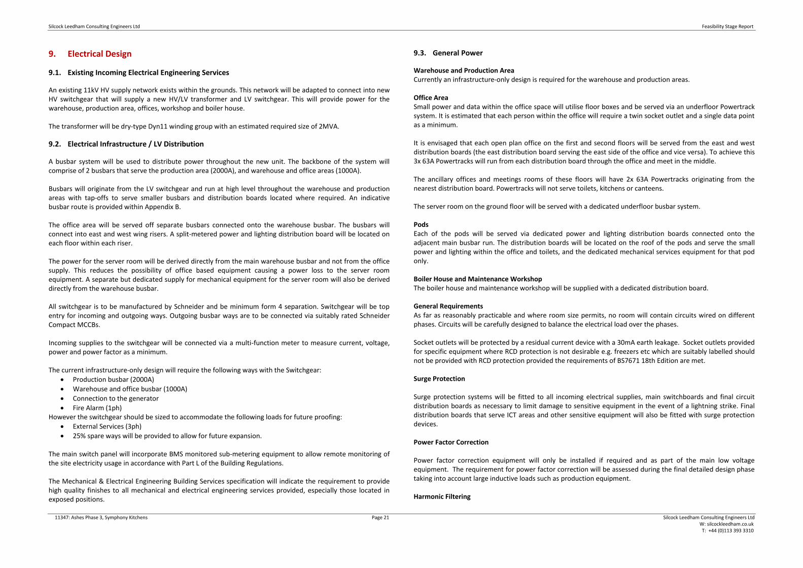
devices, automatic devices and remote control an appropriate system can be delivered. Warehouse and Production Area Currently an infrastructure only design is required for the warehouse and production areas until a later date. Office Area Lighting Office areas will utilise a LED recessed luminaire with polycarbonate diffusers to achieve a low glare and spaced at approximately every 5m2. Daylight adjustment will be utilised on luminaires adjacent to a window – inner office luminaires will not have this function. An example of this type of luminaire is pictured below:
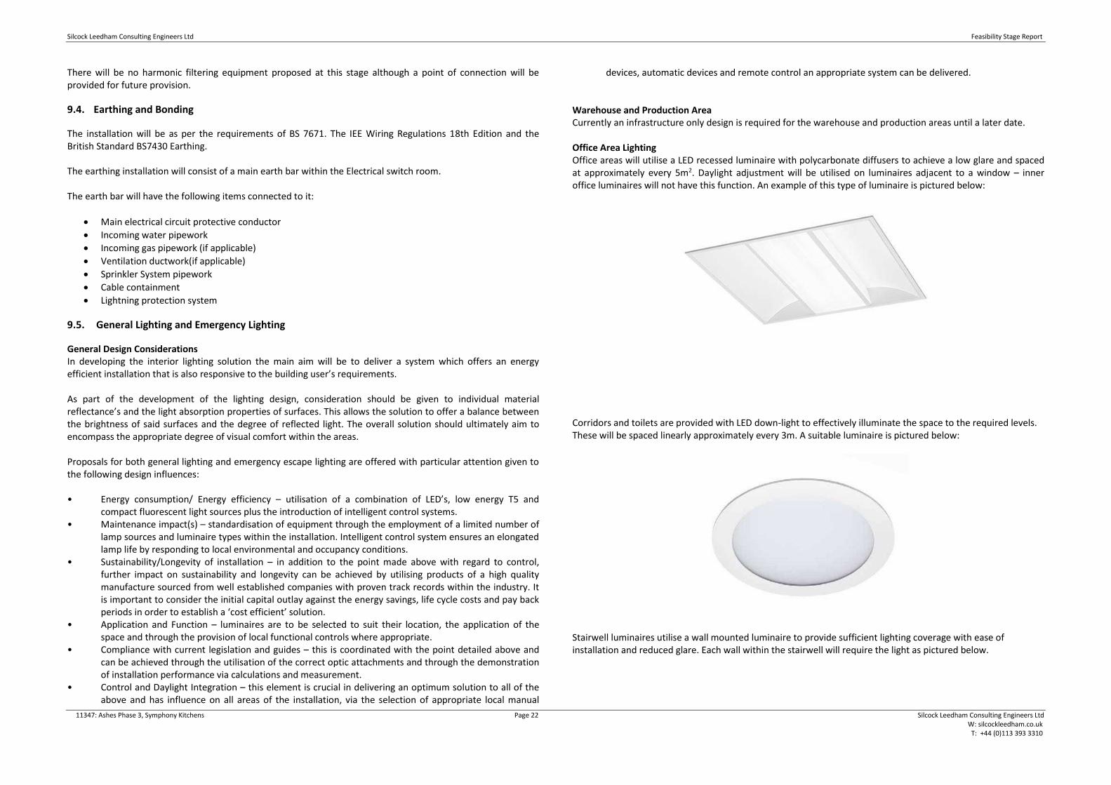
Corridors and toilets are provided with LED down-light to effectively illuminate the space to the required levels. These will be spaced linearly approximately every 3m. A suitable luminaire is pictured below:
Stairwell luminaires utilise a wall mounted luminaire to provide sufficient lighting coverage with ease of installation and reduced glare. Each wall within the stairwell will require the light as pictured below.

Silcock Leedham Consulting Engineers Ltd Feasibility Stage Report
11347: Ashes Phase 3, Symphony Kitchens Page 23 Silcock Leedham Consulting Engineers Ltd W: silcockleedham.co.uk T: +44 (0)113 393 3310
The lighting in all these areas will be controlled via presence detection to reduce energy wastage. Boiler House and Maintenance Workshops A standard utilitarian low energy LED luminaire is proposed for these areas with a louvre attachment selected to suit the local environmental conditions. Focus is on functionality and durability rather than aesthetics in these areas.
9.6. Lighting Controls Strategies
The lighting control strategy is to be developed in line with Client requirements with regard to the overall solution. The utilisation of intelligent lighting controls is key in delivering a lighting installation that is customised to suit the buildings application and Client requirements. It is fundamental in minimising energy consumption and managing the visual environment. Daylight linking and presence detection control will be used where practicable.
9.7. Emergency Lighting
Emergency lighting will be provided in accordance with the requirements of BS EN 1838 and BS5266 and the requirements of the Fire Officer. It is proposed to provide self-contained non-maintained and maintained LED emergency luminaries throughout the offices, boiler house and workshop areas. Luminaries will be provided with self-test facility.
9.8. External Lighting
An external lighting scheme in accordance with BS5489-1:2013 will be provided to facilitate safe and secure pedestrian and staff movement around the building and aid security. This will be in the form of high level luminaires mounted to the façade at approximately 15m centres. Additional luminaires will be centred on and directly above loading bays to provide sufficient lighting to the lorry cabins through the cabin’s transparent roof for night time loading/off-loading. All external lighting is to be provided by Holophane as per the existing building.
9.9. Induction Loops
Induction loop systems are not proposed for the site.
9.10. Fire Alarms
A new analogue addressable fire detection system will be installed to meet the requirement of BS5839 part 1:2017. Offices will be served via ceiling mounted detectors potentially within each area, this will be determined by the fire consultant at the subsequent stages of the design. Warehouse and production areas will utilise high level beam detectors to provide coverage in these areas. These will be evenly distributed throughout the roof space estimated at 4 per roof apex section.
9.11. Security
CCTV The CCTV systems will be designed to monitor the entry/exit points of the building and will be internally mounted only. There will be no external CCTV as part of this package. The system shall be capable of producing images and record pictures (both still and video with time and date). The system will include a centralised digital recording system located within the new server room with restricted access. Intruder Alarm System Intruder protection will be by the use of DT sensors and magnetic contact points linked to all external doors. All offices with external access (window or door) are also to be provided with DT detection. All fire escape doors will be continuously monitored during occupied hours. A local alarm will be activated when the doors have been opened.

Silcock Leedham Consulting Engineers Ltd Feasibility Stage Report
11347: Ashes Phase 3, Symphony Kitchens Page 24 Silcock Leedham Consulting Engineers Ltd W: silcockleedham.co.uk T: +44 (0)113 393 3310
The security system will have the flexibility to enable the building to be zoned (office, production area, warehouse) so that areas can be locked outside of normal hours whilst still allowing access to other areas. Access Control System Access control will be provided to restrict access of staff between warehouse and production area, and offices.
9.12. Disabled Alarm Systems
Disabled Alarms systems will be installed to all disabled toilet areas. Local audible and visual alarms will be provided with repeat indication in agreed locations. Each system is to be separate and link to a main alarm indication panel in a staff area. Each system will comprise of a pull cord with a reassurance lamp, a wall mounted reset button and an over-door illuminated indicator with tone generator. The disabled alarm call systems will also link to the office which will indicate the location of the call.
9.13. Data/Comms Installations
The data/comms installation is to be done by others, however containment routes for CAT6 cables will need to be installed.
9.14. Lightning Protection
A new lightning protection system will be considered to protect the building from lightning strikes. The lightning protection system will be designed and installed in accordance with British standard BS EN 62305. The system will be design to meet the requirements for a Lightning Protection Level (LPL) of LPL level I. A risk assessment will be carried out in accordance with BS EN 62305 during the detailed design phase to assess the actual level of protection required.

Silcock Leedham Consulting Engineers Ltd Feasibility Stage Report
11347: Ashes Phase 3, Symphony Kitchens Page 25 Silcock Leedham Consulting Engineers Ltd W: silcockleedham.co.uk T: +44 (0)113 393 3310
10. Commissioning and Maintenance
10.1. Commissioning
Commissioning refers to the process of bringing an item into operation and ensuring that it is in good working order. On building projects, this refers primarily to building services. Approved Document L1A Conservation of fuel and power in new dwellings (2010), defines commissioning as: ‘…the advancement of a fixed building service after all or part of the system has been installed, replaced or altered. The system is taken from a state of static completion to working order. Testing and adjusting, as necessary, ensure that the whole system uses no more fuel and power than is reasonable in the circumstances, without compromising the need to comply with health and safety requirements. For each system, commissioning includes the following: setting-to-work; regulation (that is, testing and adjusting repetitively) to achieve the specified performance; calibration, setting up and testing of the associated automatic control systems; and recording of the system settings and the performance test results that have been accepted as satisfactory.’ Building services requiring commissioning may include:
• Heating, cooling and ventilation systems.
• Generators.
• Switchboards.
• Water supply and sanitation.
• Pumps.
• Motors.
• Fire detection and protection systems.
• Information and communications technology (ICT) systems.
• Security systems.
• Facilities management systems.
• Process plant.
• Lifting equipment and escalators.
• Acoustic and vibration appraisals As part of the development of design proposals, the aim of this report will be to set out a commissioning strategy which will form part of the work package. The documents should set out:
• Who will be responsible for commissioning different building services
• What methods, standards and codes of practice are to be used
• What should happen to test results
• Whether commissioning is to be witnessed and if so, whom
• The documentation that is required Commissioning can benefit from the preparation of a commissioning plan, which shall be developed in accordance with BSRIA Guide BG 8/2009. 11.2 Maintenance Strategy The proposed location, size and access requirements to plantrooms will be carefully considered during the early stages of design to ensure that the project moves forward with the a clear and defined objective; to provide easily accessible plant space with a considered equipment layout which does not have a detrimental impact upon future access and space for movement, and which promotes a safe environment for maintenance and
installation works to be undertaken. Plant space has been allocated at basement level to accommodate the following:
• Main Boiler house & Office Plant Deck Spaces –Wet mechanical plant including LPHW heating installations, cold water storage and booster plant.
• Electrical switch rooms will be provided at ground floor level within a segregated area. All incoming utilities will be fed into the building via the incoming services plant areas.
Access to all plant areas shall typically be available via a staircase and lift, where lift provision will ensure large or heavy items of equipment (within reason) can be easily and safely removed from the building. Access to risers shall be via access doors located at each floor level within an easily accessible location (primarily from corridors and circulation spaces to minimise disruption). Each riser shall be adequately sized allowing sufficient space for access and maintenance.
Silcock Leedham Consulting Engineers Ltd Feasibility Stage Report
11347: Ashes Phase 3, Symphony Kitchens Page 26 Silcock Leedham Consulting Engineers Ltd W: silcockleedham.co.uk T: +44 (0)113 393 3310
11. Deliverables (Drawings, Specifications, Reports)
This report shall be read in conjunction with all other engineers and architects reports and associated documentation, along with the following appendices:
A. Existing Utility Records B. MEP Sketch proposals C. Domestic Water Load Assessment

Silcock Leedham Consulting Engineers Ltd Feasibility Stage Report
11347: Ashes Phase 3, Symphony Kitchens Page 27 Silcock Leedham Consulting Engineers Ltd W: silcockleedham.co.uk T: +44 (0)113 393 3310
12. Appendix A – Existing Utility Records

Plant Protection Cadent Block 1; Floor 1 Brick Kiln Street Hinckley LE10 0NA E-mail: [email protected] Telephone: +44 (0)800 688588
National Gas Emergency Number:
0800 111 999*
National Grid Electricity Emergency Number:
0800 40 40 90*
* Available 24 hours, 7 days/week.
Calls may be recorded and monitored.
www.cadentgas.com
Cadent is a trading name for: Cadent Gas Limited National Grid is a trading name for: National Grid is a trading name for: Registered Office: Ashbrook Court, Prologis Park, National Grid Electricity Transmission plc National Grid Gas Transmission plc Central Boulevard, Coventry CV7 8PE Registered Office: 1-3 Strand, London WC2N 5EH Registered Office: 1-3 Strand, London WC2N 5EH Registered in England and Wales, No 10080864 Registered in England and Wales, No 2366977 Registered in England and Wales, No 2006000
Will Dooley Silcock Leedham Consulting Engineers Ltd Upperbank House Stoneythorpe Horsforth Leeds LS18 4BN
Date: 05/11/2019 Our Ref: EM_GE1B_3SWP_605963 Your Ref: Symphony Group Ashes Phase 3 (LS) RE: Proposed Works, The Symphony Group plc, Pen Hill Estate, Park Spring Road Barnsley, Thank you for your enquiry which was received on 25/10/2019. Please note this response and any attached map(s) are valid for 28 days. An assessment has been carried out with respect to Cadent Gas Limited, National Grid Electricity Transmission plc's and National Grid Gas Transmission plc's apparatus. Please note it does not cover the items listed in the section "Your Responsibilities and Obligations", including gas service pipes and related apparatus. For details of Network areas please see the Cadent website (http://cadentgas.com/Digging-safely/Dial-before-you-dig) or the enclosed documentation.
As your works are at a "proposed" stage, any maps and guidance provided are for information purposes only. This is not approval to commence work. You must submit a "Scheduled Works" enquiry at the earliest opportunity and failure to do this may lead to disruption to your plans and works. Plant Protection will endeavour to provide an initial assessment within 14 days of receipt of a Scheduled Works enquiry and dependent on the outcome of this, further consultation may be required.
In any event, for safety and legal reasons, works must not be carried out until a Scheduled Works enquiry has been completed and final response received.

Your Responsibilities and Obligations
The "Assessment" Section below outlines the detailed requirements that must be followed when planning or undertaking your scheduled activities at this location.
It is your responsibility to ensure that the information you have submitted is accurate and that all relevant documents including links are provided to all persons (either direct labour or contractors) working for you near Cadent and/or National Grid's apparatus, e.g. as contained within the Construction (Design and Management) Regulations.
This assessment solely relates to Cadent Gas Limited, National Grid Electricity Transmission plc (NGET) and National Grid Gas Transmission plc (NGGT) and apparatus. This assessment does NOT include:
● Cadent and/or National Grid's legal interest (easements or wayleaves) in the land which restricts activity in proximity to Cadent and/or National Grid's assets in private land. You must obtain details of any such restrictions from the landowner in the first instance and if in doubt contact Plant Protection.
● Gas service pipes and related apparatus ● Recently installed apparatus ● Apparatus owned by other organisations, e.g. other gas distribution operators, local electricity
companies, other utilities, etc.
It is YOUR responsibility to take into account whether the items listed above may be present and if they could be affected by your proposed activities. Further "Essential Guidance" in respect of these items can be found on either the National Grid or Cadent website.
This communication does not constitute any formal agreement or consent for any proposed development work; either generally or with regard to Cadent and/or National Grid's easements or wayleaves nor any planning or building regulations applications.
Cadent Gas Limited, NGGT and NGET or their agents, servants or contractors do not accept any liability for any losses arising under or in connection with this information. This limit on liability applies to all and any claims in contract, tort (including negligence), misrepresentation (excluding fraudulent misrepresentation), breach of statutory duty or otherwise. This limit on liability does not exclude or restrict liability where prohibited by the law nor does it supersede the express terms of any related agreements.
If you require further assistance please contact the Plant Protection team via e-mail (click here) or via the contact details at the top of this response.
Yours faithfully
Plant Protection Team
Page 2 of 6

ASSESSMENT
Affected Apparatus The apparatus that has been identified as being in the vicinity of your proposed works is:
● Low or Medium pressure (below 2 bar) gas pipes and associated equipment. (As a result it is highly likely that there are gas services and associated apparatus in the vicinity)
● Above ground gas sites and equipment
Requirements
BEFORE carrying out any work you must:
● Note the presence of an Above Ground Installation (AGI) in proximity to your site. You must ensure that you have been contacted by Cadent and/or National Grid prior to undertaking any works within 10m of this site.
● Carefully read these requirements including the attached guidance documents and maps showing the location of apparatus.
● Contact the landowner and ensure any proposed works in private land do not infringe Cadent and/or National Grid's legal rights (i.e. easements or wayleaves). If the works are in the road or footpath the relevant local authority should be contacted.
● Ensure that all persons, including direct labour and contractors, working for you on or near Cadent and/or National Grid's apparatus follow the requirements of the HSE Guidance Notes HSG47 - 'Avoiding Danger from Underground Services' and GS6 – 'Avoidance of danger from overhead electric power lines'. This guidance can be downloaded free of charge at http://www.hse.gov.uk
● In line with the above guidance, verify and establish the actual position of mains, pipes, cables, services and other apparatus on site before any activities are undertaken.
Page 3 of 6

GUIDANCE
Excavating Safely - Avoiding injury when working near gas pipes: http://www.nationalgrid.com/NR/rdonlyres/2D2EEA97-B213-459C-9A26-18361C6E0B0D/25249/Digsafe_leaflet3e2finalamends061207.pdf
Standard Guidance
Essential Guidance document: http://www2.nationalgrid.com/WorkArea/DownloadAsset.aspx?id=8589934982
General Guidance document: http://www2.nationalgrid.com/WorkArea/DownloadAsset.aspx?id=35103
Excavating Safely in the vicinity of gas pipes guidance (Credit card): http://www.nationalgrid.com/NR/rdonlyres/A3D37677-6641-476C-9DDA-E89949052829/44257/ExcavatingSafelyCreditCard.pdf
Excavating Safely in the vicinity of electricity cables guidance (Credit card): http://www.nationalgrid.com/NR/rdonlyres/35DDEC6D-D754-4BA5-AF3C-D607D05A25C2/44858/ExcavatingSafelyCreditCardelectricitycables.pdf
Copies of all the Guidance Documents can also be downloaded from the National Grid and Cadent websites.
Page 4 of 6


ENQUIRY SUMMARY
Received Date 25/10/2019 Your Reference Symphony Group Ashes Phase 3 (LS) Location Centre Point: 440442, 408334 X Extent: 682 Y Extent: 724 Postcode: S72 7EZ Location Description: The Symphony Group plc, Pen Hill Estate, Park Spring Road Barnsley, Map Options Paper Size: A3 Orientation: PORTRAIT Requested Scale: 2500 Actual Scale: 1:5000 (GAS) Real World Extents: 1445m x 1835m (GAS) Recipients [email protected] Enquirer Details Organisation Name: Silcock Leedham Consulting Engineers Ltd Contact Name: Will Dooley Email Address: [email protected] Telephone: 0113 393 3310 Address: Upperbank House, Stoneythorpe, Horsforth, Leeds, LS18 4BN Description of Works Plans only. Enquiry Type Proposed Works Activity Type General Excavation Work Types Work Type: Plans Only
Page 6 of 6

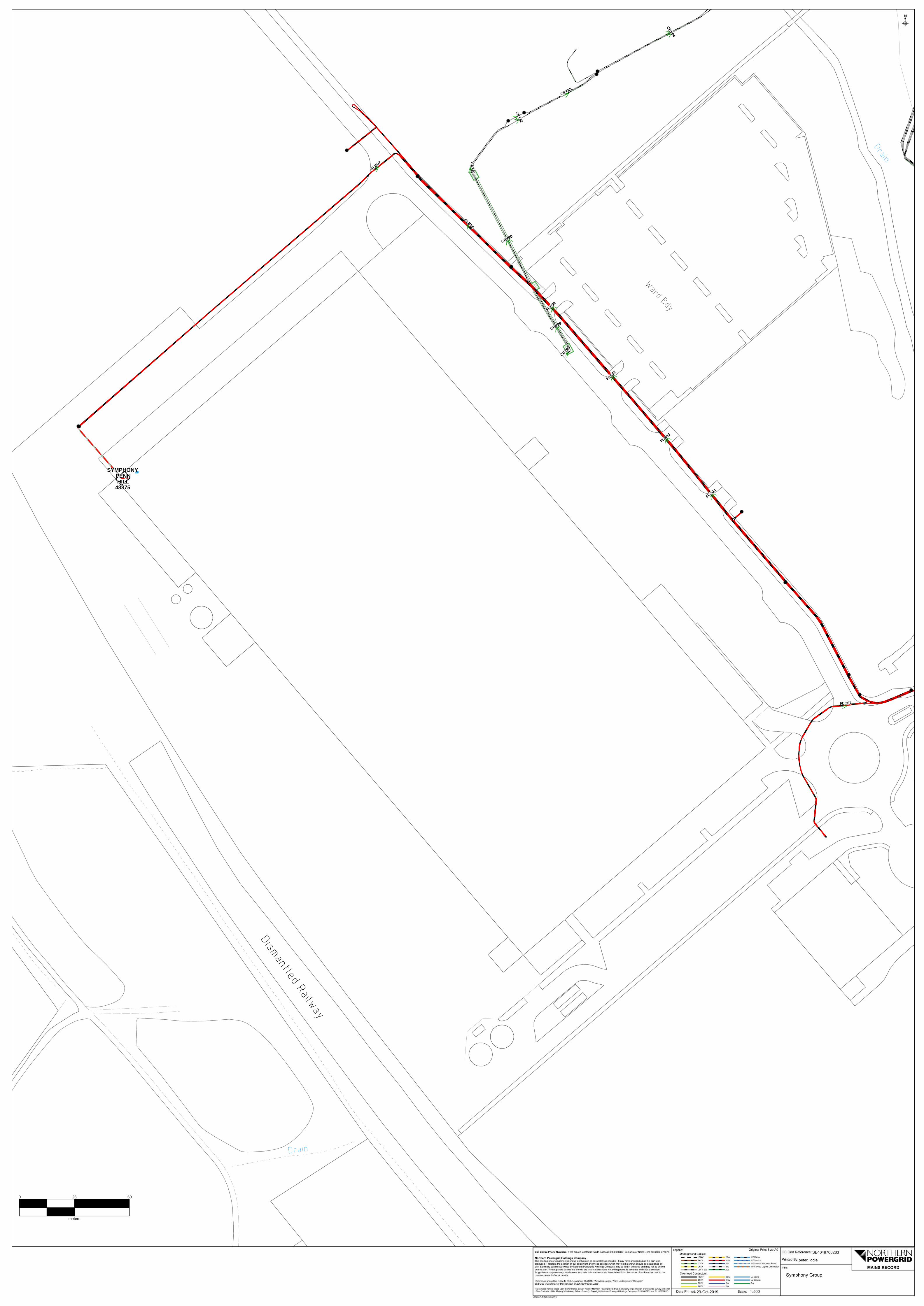
FLC07FLC07FLC07FLC07FLC07FLC07FLC07FLC07FLC07
FLB97
FLB97
FLB97
FLB97FLB97
FLB97
FLB97
FLB97
FLB97
FLC03
FLC03
FLC03
FLC03FLC03
FLC03
FLC03
FLC03
FLC03
FLB98
FLB98
FLB98
FLB98
FLB98
FLB98
FLB98
FLB98
FLB98
FLC04
FLC04
FLC04
FLC04FLC04
FLC04
FLC04
FLC04
FLC04
FLC02
FLC02
FLC02
FLC02
FLC02
FLC02
FLC02
FLC02
FLC02
FLB99
FLB99
FLB99
FLB99
FLB99
FLB99
FLB99
FLB99
FLB99
CEY94CEY94
CEY94CEY94CEY94
CEY94CEY94
CEY94CEY94
CEY92
CEY92
CEY92
CEY92
CEY92
CEY92
CEY92
CEY92
CEY92
CEY93CEY93CEY93CEY93CEY93CEY93CEY93CEY93CEY93
CEY89CEY89CEY89CEY89CEY89CEY89CEY89CEY89CEY89
CEY95
CEY95
CEY95
CEY95
CEY95
CEY95
CEY95
CEY95
CEY95
CE
Y91
CE
Y91
CE
Y91
CE
Y91
CE
Y91
CE
Y91
CE
Y91
CE
Y91
CE
Y91
CEY90CEY90CEY90CEY90CEY90CEY90CEY90CEY90CEY90
SYMPHONYSYMPHONYSYMPHONYSYMPHONYSYMPHONYSYMPHONYSYMPHONYSYMPHONYSYMPHONYPENNPENNPENNPENNPENNPENNPENNPENNPENNHILLHILLHILLHILLHILLHILLHILLHILLHILL
488754887548875488754887548875488754887548875
0 25 50
meters
29-Oct-2019 500
peter.liddle
SE4049708283

FLC07FLC07FLC07FLC07FLC07FLC07FLC07FLC07FLC07
FLB97
FLB97
FLB97
FLB97FLB97
FLB97
FLB97
FLB97
FLB97
FLC03
FLC03
FLC03
FLC03FLC03
FLC03
FLC03
FLC03
FLC03
FLB98
FLB98
FLB98
FLB98
FLB98
FLB98
FLB98
FLB98
FLB98
FLC04
FLC04
FLC04
FLC04FLC04
FLC04
FLC04
FLC04
FLC04
FLC02
FLC02
FLC02
FLC02
FLC02
FLC02
FLC02
FLC02
FLC02
FLB99
FLB99
FLB99
FLB99
FLB99
FLB99
FLB99
FLB99
FLB99
CEY94CEY94
CEY94CEY94CEY94
CEY94CEY94
CEY94CEY94
CEY92
CEY92
CEY92
CEY92
CEY92
CEY92
CEY92
CEY92
CEY92
CEY93CEY93CEY93CEY93CEY93CEY93CEY93CEY93CEY93
CEY89CEY89CEY89CEY89CEY89CEY89CEY89CEY89CEY89
CEY95
CEY95
CEY95
CEY95
CEY95
CEY95
CEY95
CEY95
CEY95
CE
Y91
CE
Y91
CE
Y91
CE
Y91
CE
Y91
CE
Y91
CE
Y91
CE
Y91
CE
Y91
CEY90CEY90CEY90CEY90CEY90CEY90CEY90CEY90CEY90
SYMPHONYSYMPHONYSYMPHONYSYMPHONYSYMPHONYSYMPHONYSYMPHONYSYMPHONYSYMPHONYPENNPENNPENNPENNPENNPENNPENNPENNPENNHILLHILLHILLHILLHILLHILLHILLHILLHILL
488754887548875488754887548875488754887548875
0 25 50
meters
29-Oct-2019 500
peter.liddle
SE4046908332

FHD79FHD79FHD79FHD79FHD79FHD79FHD79FHD79FHD79
FLB97
FLB97
FLB97
FLB97FLB97
FLB97
FLB97
FLB97
FLB97
CEY96CEY96CEY96CEY96CEY96CEY96CEY96CEY96CEY96
FLC03
FLC03
FLC03
FLC03FLC03
FLC03
FLC03
FLC03
FLC03
FLB98
FLB98
FLB98
FLB98
FLB98
FLB98
FLB98
FLB98
FLB98
FLC02
FLC02
FLC02
FLC02
FLC02
FLC02
FLC02
FLC02
FLC02
FLB99
FLB99
FLB99
FLB99
FLB99
FLB99
FLB99
FLB99
FLB99
CEY94CEY94
CEY94CEY94CEY94
CEY94CEY94
CEY94CEY94
CEY92
CEY92
CEY92
CEY92
CEY92
CEY92
CEY92
CEY92
CEY92
CEY93CEY93CEY93CEY93CEY93CEY93CEY93CEY93CEY93
CEY89CEY89CEY89CEY89CEY89CEY89CEY89CEY89CEY89
CEY95
CEY95
CEY95
CEY95
CEY95
CEY95
CEY95
CEY95
CEY95
CE
Y91
CE
Y91
CE
Y91
CE
Y91
CE
Y91
CE
Y91
CE
Y91
CE
Y91
CE
Y91
CEY90CEY90CEY90CEY90CEY90CEY90CEY90CEY90CEY90
SYMPHONYSYMPHONYSYMPHONYSYMPHONYSYMPHONYSYMPHONYSYMPHONYSYMPHONYSYMPHONYPENNPENNPENNPENNPENNPENNPENNPENNPENNHILLHILLHILLHILLHILLHILLHILLHILLHILL
488754887548875488754887548875488754887548875
0 25 50
meters
29-Oct-2019 500
peter.liddle
SE4038608443

FLB97
FLB97
FLB97
FLB97FLB97
FLB97
FLB97
FLB97
FLB97
FLB98
FLB98
FLB98
FLB98
FLB98
FLB98
FLB98
FLB98
FLB98
FLB99
FLB99
FLB99
FLB99
FLB99
FLB99
FLB99
FLB99
FLB99
CEY92
CEY92
CEY92
CEY92
CEY92
CEY92
CEY92
CEY92
CEY92
CEY93CEY93CEY93CEY93CEY93CEY93CEY93CEY93CEY93
CEY89CEY89CEY89CEY89CEY89CEY89CEY89CEY89CEY89
CEY95
CEY95
CEY95
CEY95
CEY95
CEY95
CEY95
CEY95
CEY95
CE
Y91
CE
Y91
CE
Y91
CE
Y91
CE
Y91
CE
Y91
CE
Y91
CE
Y91
CE
Y91
CEY90CEY90CEY90CEY90CEY90CEY90CEY90CEY90CEY90
SYMPHONYSYMPHONYSYMPHONYSYMPHONYSYMPHONYSYMPHONYSYMPHONYSYMPHONYSYMPHONYPENNPENNPENNPENNPENNPENNPENNPENNPENNHILLHILLHILLHILLHILLHILLHILLHILLHILL
488754887548875488754887548875488754887548875
0 25 50
meters
29-Oct-2019 500
peter.liddle
SE4034408501
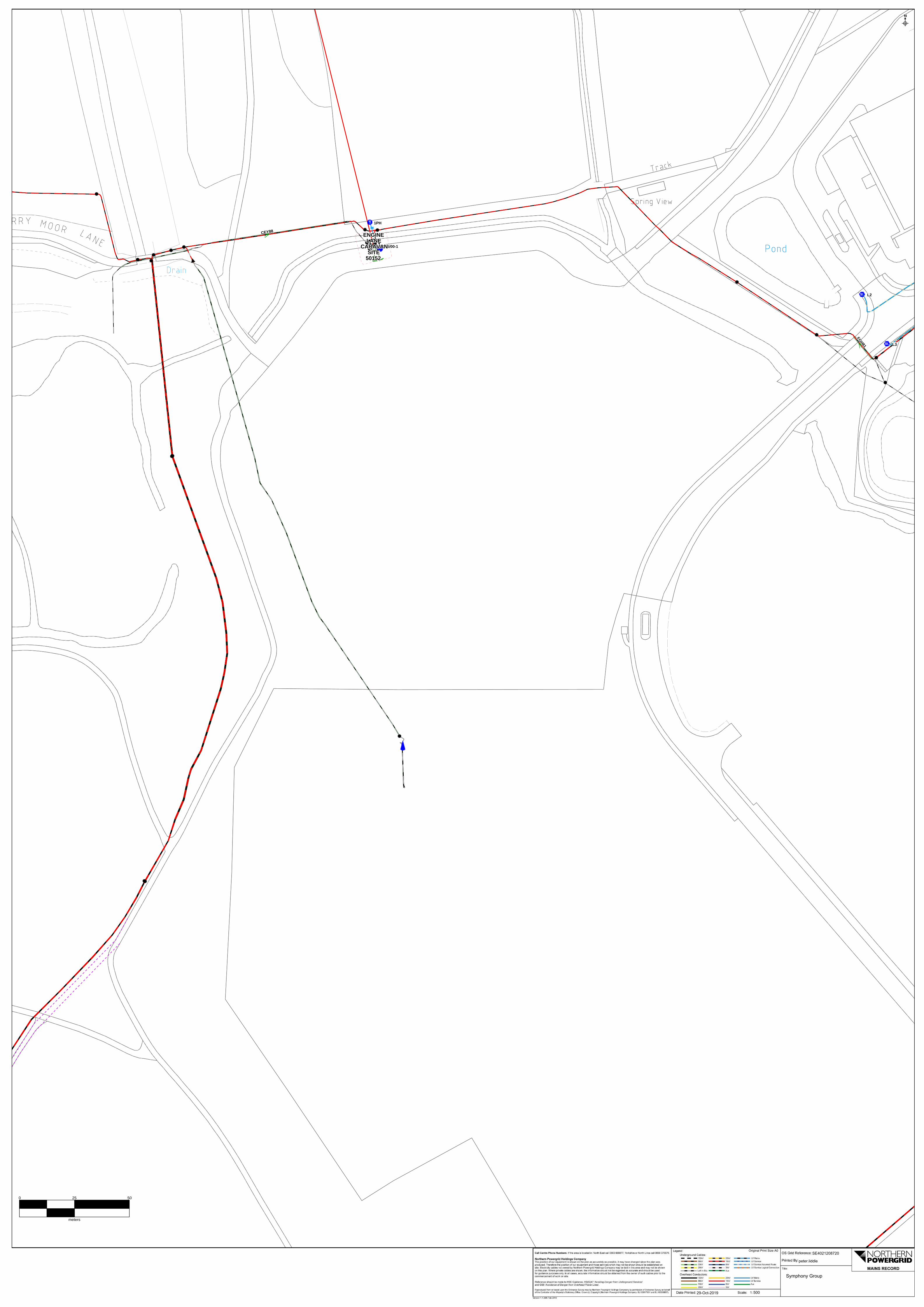
1PH
L3
L2
FGH81
FGH81
FGH81
FGH81
FGH81
FGH81
FGH81
FGH81
FGH81
CEY88CEY88CEY88CEY88CEY88CEY88CEY88CEY88CEY88
W2156/00-1
ENGINEENGINEENGINEENGINEENGINEENGINEENGINEENGINEENGINELANELANELANELANELANELANELANELANELANE
CARAVANCARAVANCARAVANCARAVANCARAVANCARAVANCARAVANCARAVANCARAVANSITESITESITESITESITESITESITESITESITE
501525015250152501525015250152501525015250152
0 25 50
meters
29-Oct-2019 500
peter.liddle
SE4021208720

Silcock Leedham Consulting Engineers Ltd Feasibility Stage Report
11347: Ashes Phase 3, Symphony Kitchens Page 28 Silcock Leedham Consulting Engineers Ltd W: silcockleedham.co.uk T: +44 (0)113 393 3310
13. Appendix B – MEP Sketch Proposals
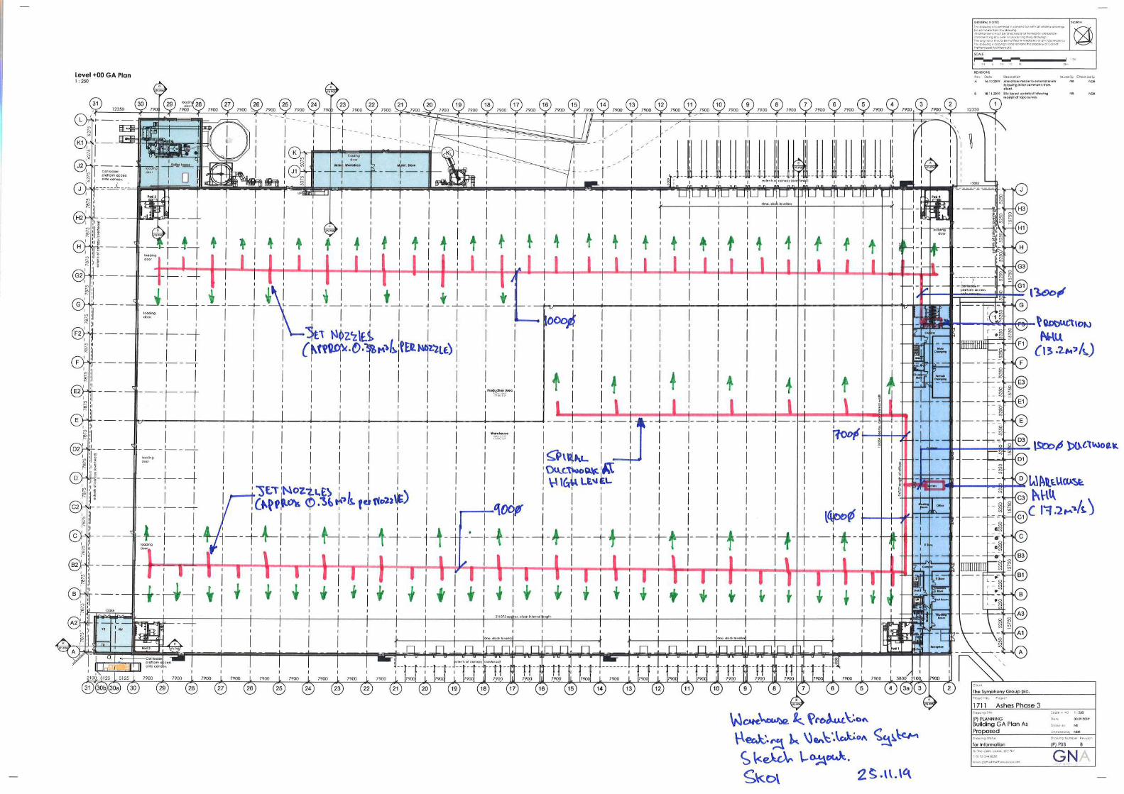

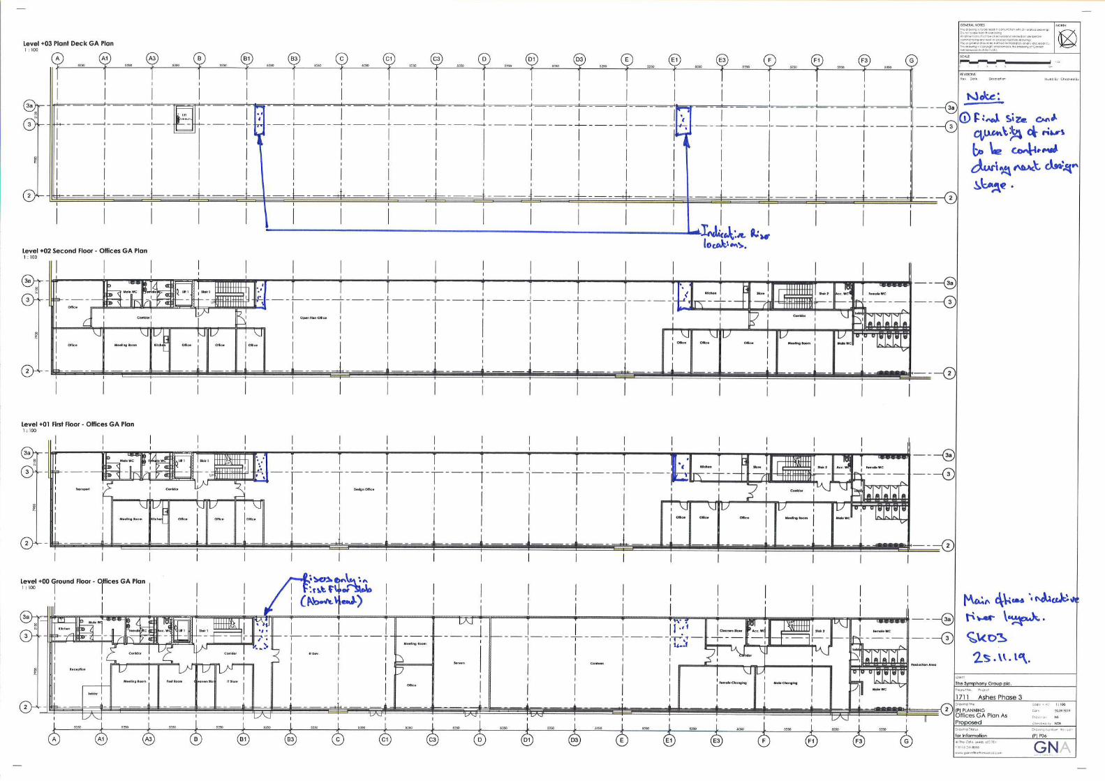
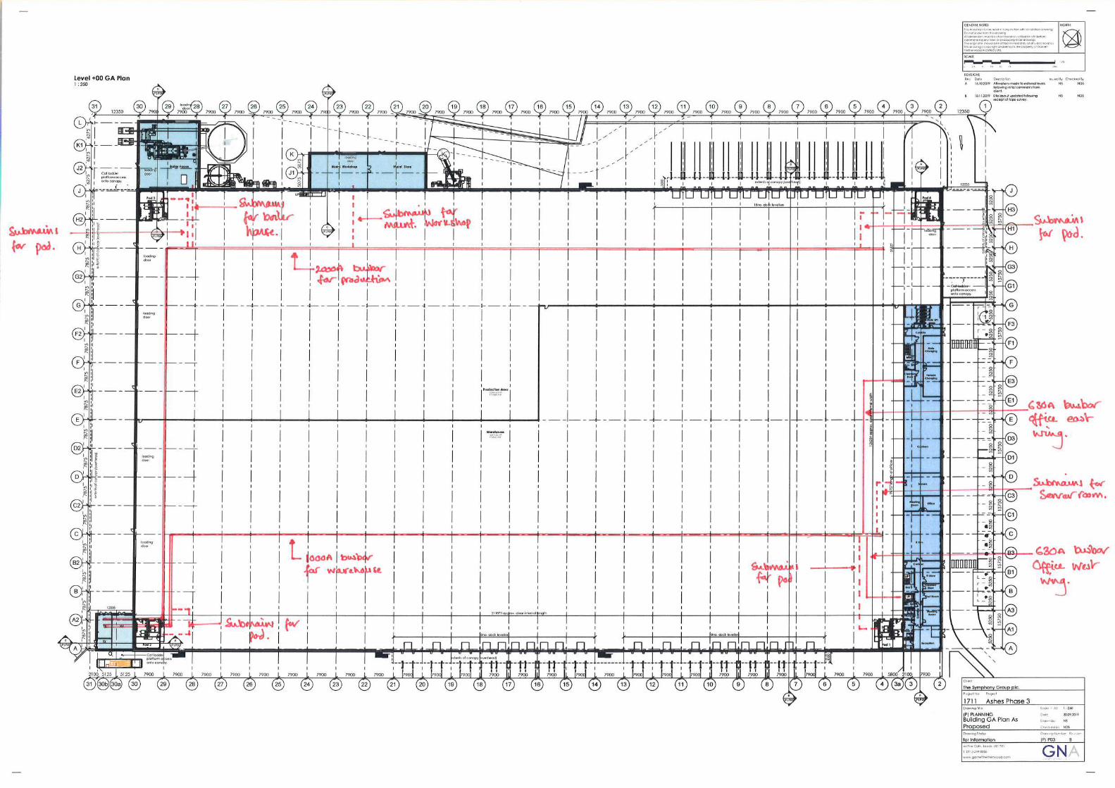
Silcock Leedham Consulting Engineers Ltd Feasibility Stage Report
11347: Ashes Phase 3, Symphony Kitchens Page 29 Silcock Leedham Consulting Engineers Ltd W: silcockleedham.co.uk T: +44 (0)113 393 3310
14. Appendix C – Domestic Water Load Assessment
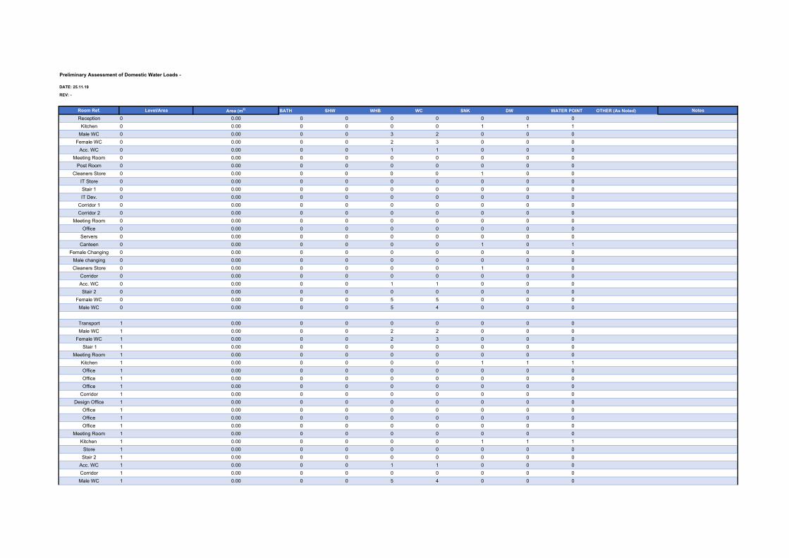
DATE: 25.11.19
REV: -
Room Ref. Level/Area Area (m2) BATH SHW WHB WC SNK DW WATER POINT OTHER (As Noted) Notes
Reception 0 0.00 0 0 0 0 0 0 0Kitchen 0 0.00 0 0 0 0 1 1 1
Male WC 0 0.00 0 0 3 2 0 0 0Female WC 0 0.00 0 0 2 3 0 0 0
Acc. WC 0 0.00 0 0 1 1 0 0 0Meeting Room 0 0.00 0 0 0 0 0 0 0
Post Room 0 0.00 0 0 0 0 0 0 0Cleaners Store 0 0.00 0 0 0 0 1 0 0
IT Store 0 0.00 0 0 0 0 0 0 0Stair 1 0 0.00 0 0 0 0 0 0 0IT Dev. 0 0.00 0 0 0 0 0 0 0
Corridor 1 0 0.00 0 0 0 0 0 0 0Corridor 2 0 0.00 0 0 0 0 0 0 0
Meeting Room 0 0.00 0 0 0 0 0 0 0Office 0 0.00 0 0 0 0 0 0 0
Servers 0 0.00 0 0 0 0 0 0 0Canteen 0 0.00 0 0 0 0 1 0 1
Female Changing 0 0.00 0 0 0 0 0 0 0Male changing 0 0.00 0 0 0 0 0 0 0Cleaners Store 0 0.00 0 0 0 0 1 0 0
Corridor 0 0.00 0 0 0 0 0 0 0Acc. WC 0 0.00 0 0 1 1 0 0 0Stair 2 0 0.00 0 0 0 0 0 0 0
Female WC 0 0.00 0 0 5 5 0 0 0Male WC 0 0.00 0 0 5 4 0 0 0
Transport 1 0.00 0 0 0 0 0 0 0Male WC 1 0.00 0 0 2 2 0 0 0
Female WC 1 0.00 0 0 2 3 0 0 0 Stair 1 1 0.00 0 0 0 0 0 0 0
Meeting Room 1 0.00 0 0 0 0 0 0 0Kitchen 1 0.00 0 0 0 0 1 1 1Office 1 0.00 0 0 0 0 0 0 0Office 1 0.00 0 0 0 0 0 0 0Office 1 0.00 0 0 0 0 0 0 0
Corridor 1 0.00 0 0 0 0 0 0 0Design Office 1 0.00 0 0 0 0 0 0 0
Office 1 0.00 0 0 0 0 0 0 0Office 1 0.00 0 0 0 0 0 0 0Office 1 0.00 0 0 0 0 0 0 0
Meeting Room 1 0.00 0 0 0 0 0 0 0Kitchen 1 0.00 0 0 0 0 1 1 1
Store 1 0.00 0 0 0 0 0 0 0Stair 2 1 0.00 0 0 0 0 0 0 0
Acc. WC 1 0.00 0 0 1 1 0 0 0Corridor 1 0.00 0 0 0 0 0 0 0Male WC 1 0.00 0 0 5 4 0 0 0
Preliminary Assessment of Domestic Water Loads -

Female WC 1 0.00 0 0 5 5 0 0 0
Office 2 0.00 0 0 0 0 0 0 0Office 2 0.00 0 0 0 0 0 0 0
Male WC 2 0.00Female WC 2 0.00
Stair 1 2 0.00 0 0 0 0 0 0 0Meeting Room 2 0.00 0 0 0 0 0 0 0
Kitchen 2 0.00 0 0 0 0 1 1 1Office 2 0.00 0 0 0 0 0 0 0Office 2 0.00 0 0 0 0 0 0 0Office 2 0.00 0 0 0 0 0 0 0
Open Plan Office 2 0.00 0 0 0 0 0 0 0Kitchen 2 0.00 0 0 0 0 1 1 1Store 2 0.00 0 0 0 0 0 0 0Office 2 0.00 0 0 0 0 0 0 0Office 2 0.00 0 0 0 0 0 0 0Office 2 0.00 0 0 0 0 0 0 0
Meeting Room 2 0.00 0 0 0 0 0 0 0Male WC 2 0.00
Female WC 2 0.00
Male WC P1 0.00 0 0 2 2 0 0 0Female WC P1 0.00 0 0 2 2 0 0 0
Cleaners Store P1 0.00 0 0 0 0 1 0 1Mess Area P1 0.00 0 0 0 0 0 0 0FF Office P1 0.00 0 0 0 0 0 0 0
Male WC P2 0.00 0 0 2 2 0 0 0Female WC P2 0.00 0 0 2 2 0 0 0
Cleaners Store P2 0.00 0 0 0 0 1 0 1Mess Area P2 0.00 0 0 0 0 0 0 0FF Office P2 0.00 0 0 0 0 0 0 0
Male WC P3 0.00 0 0 2 2 0 0 0Female WC P3 0.00 0 0 2 2 0 0 0
Cleaners Store P3 0.00 0 0 0 0 1 0 1Mess Area P3 0.00 0 0 0 0 0 0 0FF Office P3 0.00 0 0 0 0 0 0 0
0 0 0.00Male WC P4 0.00 0 0 2 2 0 0 0
Female WC P4 0.00 0 0 2 2 0 0 0Cleaners Store P4 0.00 0 0 0 0 1 0 1
Mess Area P4 0.00 0 0 0 0 0 0 0FF Office P4 0.00 0 0 0 0 0 0 0
TOTAL 0 0 48 47 12 5 10TOTAL COLD LU 0 0 72 94 36 15 15TOTAL HOT LU 0 0 72 0 36 0 0
BS6700:2006 Loading Units Hot ColdBATH 10 10SHW 3 3WHB 1.5 1.5
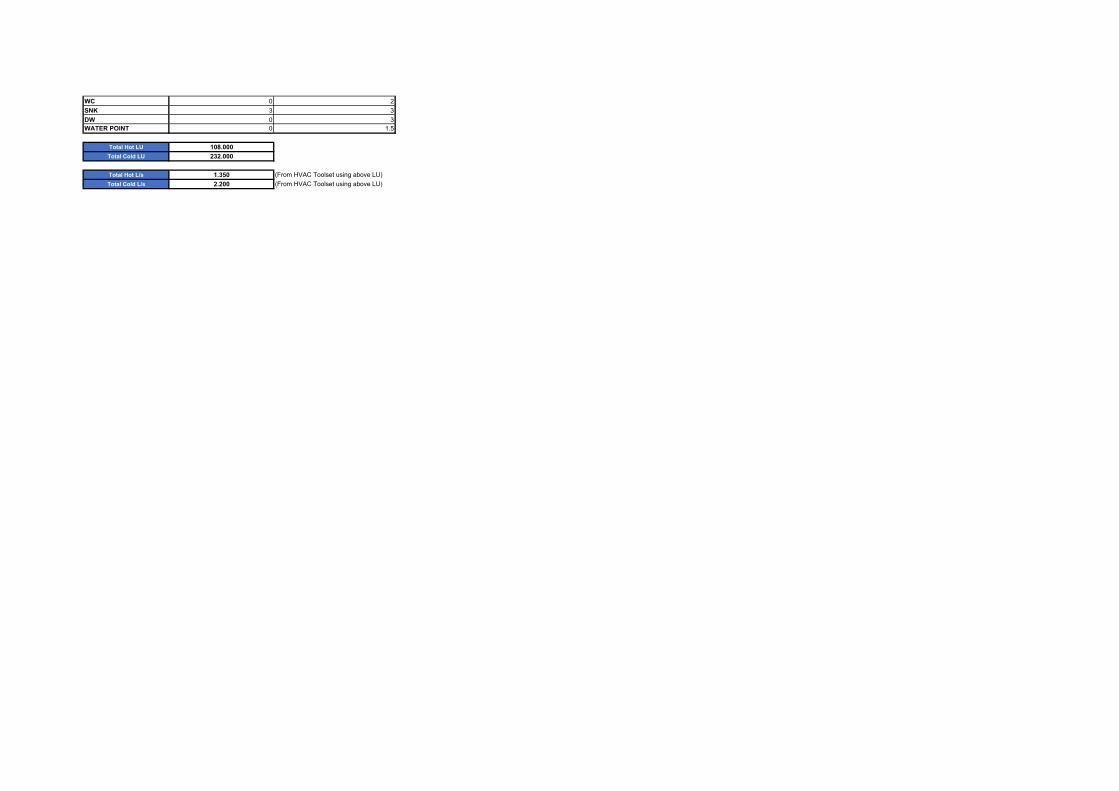
WC 0 2SNK 3 3DW 0 3WATER POINT 0 1.5
Total Hot LU 108.000Total Cold LU 232.000
Total Hot L/s 1.350 (From HVAC Toolset using above LU)Total Cold L/s 2.200 (From HVAC Toolset using above LU)