Embed Size (px)
Citation preview

A SET OF SHELL FINITE ELEMENTSFOR DYNAMIC ANALYSIS OF COOLING TOWERS
Prepared by
T.Y. Yang and Rakesh K. KapaniaSchool of Aeronautics and Astronautics
Purdue UniversityWest Lafayette t Indiana 47907
Submitted to
THE NATIONAL SCIENCE FOUNDATION
June 10 t 1982
Any opinions, findings, conclusionsor recommendations expressed in thispublication are those of the author(s)and do not necessarily reflect the viewsof the National Science Foundation.


50272 -101
REPORT DOCUMENTATION 11. REPORT NO.
PAGE NSFjCEE-82026 I~
59-37
C. Titl. and Subtltl.
Set of Shell Finite elements for Dynamic Analysis ofCooling Towers
7. Author(.)
T.Y. Yang, R.K. Kapania
5. R.port Data
June 1982
a. P.rformln. Or••nlntlon Rept. No.
11. Contl1lct(C) Dr Grant(G) No.
10. Proj.ct/Task/Work Unit No.9. P.rform;n. Orlf.nintion N.m. and Addr•••
Purdue UniversitySchool of Aeronautics and AstronauticsWest Lafayette, IN 47907 (C)
(G)CEE8024883
1~ Sponsorin. Or,.nlzation Nam. and Addr...
Directorate for Engineering (ENG)National Science Foundation1800 G Street, N.W.WashinqtQn, DC 20550
15. Suppl.m.nt.ry Note.Submitted by: Communications Program (OPRM)
National Science FoundationWashington, DC 20550 ------ . ---- -
13. Type of R.port & Period Cover.d
lC.
-- -- --------------4.us. Ab.tr.ct (Limit: 200 wordS)
A set of shell finite elements is adopted, modified, or extended to study the dynamic responses of complex, thin shell structures and column-supported cooling towersdue to earthquake excitation and wind loads. The elements are formulated to achieveoptimum finite element modeling of the column-supported cooling towers according tothe distributions of dominating bending and membrane stresses, and to model thevulnerable shell column region using discrete column elements and quadrilateral shellshell elements. Examples are provided to evaluate a single type, combined types,and the whole set of elements. The whole set of elements is used to determine thefirst three eccentric natural frequencies of a column-supported cooling tower. Themean stresses and displacements in a fi~ed base cooling tower are determined and theresults are found to be in excellent agreement with the known alternative solutions.
17. Documant Analysl. a. Dascriptors
Structural analysisDynamic structural analysisEarthquakesCoo 1i ng towersb. Id.ntlfi.rs/Open·Endad T.rms
Matrix methods
c. COSATI Fi.ld/Group
Shell structuresThin shell structuresMathematical models
T.Y. Yang, JPI
Loads (forces)StressesDisplacement
II. Availability Statamant
NTIS
(Saa ANSI-l39.11)
Ill. Security CI... (Thi. R.port)
20. security Cia•• (Thi. Pa••)
S•• In.truction. on R....r••
21. No. of P••••
22. Prica
OPTIONAL FORM 272 (4-77)(Formerly NTI5-3S)D.partmant of Comm.rc.


ACKNOWLEDGMENTS
This study is sponsored by the National Science Foundation under
Grant #CEE-8024883. The authors gratefully acknowledge Dr. S.C. Liu
of NSF for his technical guidance. Dr. S.C. Liu is the program manager
for year one and Dr. Michael P. Gaus will be the program manager for
year two. The project period is from 6/1/81 to 5/31/83.
The authors also wish to acknowledge the Co-principal Investigator
Professor Y.K. Lin of the University of Illinois at Urbana-Champaign
and Professor Anshel J. Schiff of Purdue University for their technical
advices. Mr. Sunil Saiga1, another research assistant to this project,
has provided assistance through technical discussions.
"


TABLE OF CONTENTS
Page
. . . . . . . 18
1
i
i i
6
6
6
7
. 10
10
• • 14
14
. . i v
A. The Column Element. .'.
B. The Doubly-Curved Quadrilateral General Shell Element.
(a) Element Geometry . . .
(b) Di sp1acement Functi ons. ....
(c) Element Formulation.
(d) Evaluative Analysis.
i Rigid Body Modes.
ii A Fixed Base Cooling Tower under
its own Weight. . . . . . 16
iii Orthotropic Cylindrical Shell under
Internal Pressure ...
iv Axisymmetric Vibration of a Clamped
Spherical Cap . . . . . . . . . . . . . . . . . . 18
v Axisymmetric Buckling of a Simply-Supported
Cylinderical Shell Subjected to Uniform Axial
Compressive Stress 21
vi Free Vibrations of a Fixed Base Cooling Tower
Without and With Initial Stresses 21
LIST OF TABLES.
LIST OF FIGURES
ABSTRACT...
INTRODUCTION. . . .. ....
CHAPTER 1 - DESCRIPTION OF VARIOUS FINITE ELEMENTS AND
THEIR FORMULATION .
III

Page
.. 40
.43
. .. 53
. . .56
.28
.29
. .. 32
. .32
.33
.34
.34
C. The Quadrilateral General-Membrane Transition Element..
D. The Triangular Filler Membrane Element.
(a) Element Geometry ...
(b) Displacement Functions..
(c) Element Formulation
(d) Evaluative Analysis
i Axisymmetric Vibration of a Spherical Cap.
ii First Eccentric Frequency of a Fixed Base
Coo1i ng Tower. . . . . . . . . . . . . . . . . . .37
CHAPTER 2 - THREE ECCENTRIC FREQUENCIES OF A COLUMN-SUPPORTED
COOLING TOWER USING THE WHOLE SET OF ELEMENTS . .
CHAPTER 3 - STATIC ANALYSIS OF A FIXED BASE COOLING TOWER DUE TO
WIND LOAD . . . . .
CHAPTER 4 - CONCLUDING REMARKS.
REFERENCES. . . . . . . . . . .
.tV

LIST OF TABLES
Table Page
1 Eigenvalues of the 36 d.o.f. General Shell Element ~ . . 15
2 Natural Frequencies of a Fixed Base Cooling Tower for
Various Modes. . . . . . . . . . . . • . . . . . . . . 23
3 Natural Frequencies of Axisymmetric Modes of a Spherical
Cap. . . . . . . . . . . . . . . . . . . . . . . . . . . . . 36
4 The Eccentric Natural Frequencies of a Column-Supported
Cool ing Tower. . . . . . . . . . . . . . . . . . . . . . . . 42
v
i

ii
LIST OF FIGURES
Figure Page
1 An Efficient Modeling for a COlumn-Supported Cooling
Tower Using a Set of Elements . . 4
2 A Doubly-Curved Quadrilateral General Shell Element and a
Doubly-Curved Triangular Membrane Filler Element. . . 8
3 Circumferential Force (Ne) and Meridional Force (N~) in a
Cooling Tower Under its Own Weight (1 1b = 4.45 N. 1 ft =
0.305m) .
4 Axial Bending Moment and Circumferential Stress Resultant
Along the Length of the Orthotropic Cylinder (Length = 20
in.; 1 in. = 2.54 cm. 1b. = 4.45 N). . . . . .
5 Axisymmetric Vibration of a Spherical Cap with Subtending
Angle of 11.28° E = 3xl07 psf. v = 0.3 and p =4.5 lb.
·17
• 19
sec2/ft4 • (1 lb = 4.45 N. 1 ft = 0.305 m) .. . .. 20
6 Effect of Uniform Circumferential Force on Frequency
Ratio for a Fixed Base Cooling Tower for Various ~1odes
(m = Number of Meridional Mode; n = Number of
Circumferential Waves; 1 1b = 4.45 N. 1 ft = 0.305 m) .24
7 Effect of Uniform Meridional Force on Frequency Ratio for
a Fixed Base Cooling Tower for Various Modes (m = Number
of Meridional Mode; n = Number of Circumferential Waves;
1 lb = 4.45 N. 1 ft = 0.305 m) . . . . . . . . . . .25
8 Effect of Uniform Meridional Stress Resultant (N ) on the. . ~
Shape of the (m = 1. n = 6) Mode of the Fixed Base
Cooling Tower....
VI
. . . . .27

iii
Figure Page
9 Axisymmetric Vibrations of a Spherical Membrane with a
Subtending Angle of 60°, E = 3xl07 psf; v = 0.3;
p = 4.5 lbs-sec2j ft 4 (1 lb =4.45 N, 1 ft = 0.305 m) ... 35
10 First Eccentric Natural Frequency of a Fixed Base
Hyperbolic Cooling Tower Using the Two Types of
Triangular Membrane Elements .
11 Pressure Distribution Around the Circumference. (With
. . 38
Internal Suction Cp = 0.5) • . . . . . . . . . .. .. 46
12 Meridional Stress Resultant (N~) Due to Wind Load
(pV2j2 = 1 psf; 1 lb = 4.5 N, 1 ft = 0.305 m).. . ... 48
13 Meridional Bending Moment (M~) Due to Wind Load
(pV 2/2 = 1 psf; 1 lb = 4.5 N, 1 ft = 0.305 m). . .... 49
14 Radial Deflection at e = 0 Due to Wind Load
(pV2/2 = 1 psf; thickness = 7 in; 1 lb = 4.5 N,
1 ft = 0.305 m). . . . . . . . . . . . . .
15 Distribution of Membrane Stress Resultants N~ and Neat the Shell Base Due to Wind Load (pV2j2 = 1 psf,
. . . 50
1 lb = 4.5 N; 1 ft = 0.305 m) .
VII
. . . . 51

iv
ABSTRACT
A set of shell finite elements is adopted, modified or extended to
study the dynamic responses of complex thin shell structures in general,
and column supported cooling towers in particular, due to earthquake
excitation and wind loads. The elements are formulated intending to
achieve optimum finite element modeling of the column-supported cooling
towers according to the distributions of dominating bending and membrane
stresses and intending to model the vulnerable shell-column region using
discrete column elements and quadrilateral shell elements. The set
includes: a 16 d.o.f. column element; a 48 d.o.f. doubly-curved quadri-
lateral general shell element; a 42 d.o.f. doubly-curved general-membrane
transition element; a 21 d.o.f. and a 39 d.o~f. doubly-curved triangular
membrane filter element; and a 28 d.o.f. doubly-curved quadrilateral
membrane element.
Examples are illustrated to evaluate a single type, combined types
and the whole set of elements. The 48 d.o.f. high-order quadrilateral
curved shell element is employed to analyze: (1) a fixed base cooling
tower subjected to its own weight; (2) an orthotropic cylindrical shell
with both edges clamped subjected to internal pressure; (3) axisymmetric
free vibrations of a spherical cap with base clamped; (4) axisymmetric
buckling of a simply-supported cylinderical shell subjected to axial
compression; and (5) free vibration analysis of a fixed base cooling
tower with and without initial stresses. The 42 d.o.f. general-membrane
transition element is tested by employing it in conjunction with the
general 48 d.o.f. element and an existing 28 d.o.f. high-precision membrane
element to determine the first eccentric natural frequency of a fixed
" , ,VIII

v
base cooling tower. The 21 d.o.f. and the 39 d.D.f. membrane triangular
Ifiller ' elements are evaluated through their performance on two examples:
(1) axi symmetric free vibrati on of a spheri ca1 membrane cap with base on
"rollers ll; and (2) first eccentric natural frequency of a fixed base
COO li ng tower.
The whole set of elements is then employed to determine the first
three eccentric natural frequencies of a column-supported cooling tower.
The mean stresses and displacements in a fixed base cooling tower
due to a wind velocity of 29 ft/sec. and assuming Batch and Hopley pres-
sure distribution along the circumference are also determined using the
48 d.o.f. general shell element. All results are found to be in excellent
agreement with the known alternative solutions.
The modeling may be used in seismic response analysis of cooling
towers for obtaining detail stress distribution in the vulnerable shell
column region. This model may be extended to include material nonlinearity
in the shell-column region for the seismic response studies. This model
may also be used to study the dynamic response due to fluctuating compo-
nents of wind velocity.
,IX


INTRODUCTION
Thin shell structures are built for a variety of functions. Natural
draught cooling towers are built up to 590 ft (180 meter) in height to
cool water heated up in the condensers so as to avoid thermal pollution
of rivers. lakes. and sea shores. Chimneys are vital to power plant
operation. The portion of the chimney containing flue openings behaves
like a shell and is analyzed using shell theory. Storage tanks and
pressure vessels are usually supported by slender columns and cylindrical
skirts to provide elevation. Domes, hangars, and hypars are built on
columns and walls for aesthetic and practical purposes.
Due to the slenderness of the supporting columns and the height and
large dimensions of the shells. such structures are vulnerable to earth
quake and wind disturbances. Evidences of failure of shell structures
have not been uncommon. As recently as July 9. 1980, a shell hangar in
Waterloo. Iowa, collapsed due to a wind storm. The catastrophic failure
of the cooling towers at Ferrybridge. England in 1965 during a gust storm
(1) and the collapse of another cooling tower at Ardeer, Scotland in 1973
(2) are the evidences of the vulnerability of the cooling towers.
Many investigators have conducted studies to better understand the
stability and dynamic response behaviors of the cooling towers. Construc
ions of these monumental structures in the zones of high seismic risk or
high wind have further intensified these investigations. In order to study
the dynamic response and to properly interpret the characteristics of the
loads in terms of their effect on the dynamic response of cooling towers,
accurate determination of the free vibration frequencies and modes is
necessary.

2
Early free vibration analyses for cooling towers were conducted for
the cases of fixed bases. Carter, Robinson and Schnobrich (3) used numer
cal integration method, Hashish and Abu~Sitta (4) used a modified finite
difference method, and Sen and Gould (5) developed a rotational shell
finite element for such studies. A review of free vibration analysis of
cooling towers can be found in Ref. 6. The presence of discrete column
supports, however, significantly alters the condition of the physical
restraint at the base and thereby greatly influences the dynamic response.
This makes an accurate modeling of the column supports highly imperative.
A number of efforts was made to model the base column supports.
Gould, Sen, and Suryoutomo (7) used a rotational shell element which
possesses averaged-out properties of the individual columns. Basu and
Gould (8) modified this approach and improved the results by developing
a series of open type axisymmetric shell elements to model the columns.
Gran and Yang (9, 10) used an alternative approach by using quadrilateral
flat plate finite elements to model the shell and discrete column elements
to model the columns. The advantage is that the columns were modeled
more accurately but the shell is obviously modeled less efficiently as
compared to that by using rotational shell elements (7,8). There appears
to be a need for the development of more accurate and efficient quadrila
teral shell elements by including proper curvatures. The modeling using
quadrilateral shell elements and discrete column elements has the advan
tage and capability of obtaining detail response results, for both linear
and materially nonlinear cases, in the vulnerable region of shell-column
joints.
In this study, a sophisticated 3-D column element is used to model
the discrete supporting columns. The response behavior of the cooling

3
tower shell due to earthquake load is, in general, predominantly membrane
except in the vicinity of the base where bending behavior is also signifi
cant. A highly efficient high-order quadrilateral membrane element was
developed by Gran and Yang (11) to be used in modeling the portion of
the shell dominated by membrane forces. This element is used in combina
tion with a quadrilateral doubly-curved general shell element (12) to
model the cooling tower shell. An element formu1ative procedure, which
is slightly different from that used in Ref. 12, is given here. An exten
sion of this element to the analysis of buckling and vibration of a cool
ing tower shell under the effect of initial forces is also given. Thus
an efficient modeling can be achieved by using the membrane elements and
the general shell elements to model the regions dominated by membrane
forces alone and by combined bending and membrane forces, respectively.
Such efficient mixed modeling requires the use of a quadrilateral
transition element which is compatible with the general shell elements
at the lower edge and with the pure membrane elements at the upper edge.
This element is developed here.
The number of quadrilateral general shell elements needed to model
the base layer of the shell has to be the same as the number of the upper
joints of the supporting columns. This number can be quite high. On the
other hand, the number of membrane elements needed to model an upper layer
of the shell can be relatively less. A triangular membrane filler element
which can connect two nodal points at the base and one on the top, and
vi ce versa, is thus developed to fi 11 between a fi ne 1ayer and a coarse
layer of quadrilateral elements.
A schematic diagram showing the modeling of a cooling tower using
the five types of elements is given in Fig. 1. The five types are:
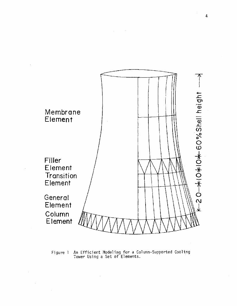
MembraneElement
FillerElementTransitionElement
GeneralElementColumnElement
T
Q).£::.(f)
~oo(0
-fo-*o
4
Fi gure 1 An Efficient Modeling for a Column-Supported CoolingTower Using a Set of Elements. .

5
(1) column element; (2) doubly-curved quadrilateral general shell
element; (3) doubly-curved quadrilateral general-membrane transition
element; (4) doubly-curved triangular filler membrane element; and
(5) doubly-curved quadrilateral membrane element.
All these elements are described in greater details along with their
formulative procedures in Chapter 1. A series of examples is chosen to
step-by-step evaluate the performance of the elements adopted, modified
and extended in this study. In Chapter 2, the whole set of elements is
employed in the free vibration analysis of a column supported cooling
tower. In Chapter 3, the stresses and displacements in a fixed base
cooling tower due to the static component of the wind load are determined.
Concluding remarks are made in Chapter 4. A brief description of the
research, presently in progress, is also given in this Chapter.

6
CHAPTER 1
DESCRIPTION OF VARIOUS FINITE ELEMENTSAND THEIR FORMULATIONS
THE COLUMN ELEMENT
Since the supporting columns are very critical components of the
cooling tower and their behavior is dominated by axial forces and axial
motions, it is desirable to use a sophisticated column element that con
tains axial displacements as well as axial strains as degrees of freedom.
A four d.o.f. bar element having both the axial displacement and the axial
strain d.o.f.1s at each end was developed by Yang and Sun (13) which was
proven to be highly accurate and highly efficient for axial vibration
analysis. Such an element was extended in this study to the general
3-D form.
The present column element contains 8 d.o.f.1s at each of the two
joints: three orthogonal displacements, u, v~ and w in the n, ~ and s
directions, respectively; two strain components dU/dn and dV/d~ ; two
rotations dW/d~ and dW/dn and a rotation dV/dn about the s axis. The
curvilinear coordinates n, sand s are along the meridional, circumferen
tial, and normal-to-surface directions, respectively, of the shell.
THE DOUBLY CURVED QUADRILATERAL SHELL ELEMENT
A comprehensive review of the developments of thin shell finite
elements is given by Ashwell and Gallagher (14). Most notable of the
developments of quadrilateral shell elements are: the 24 d.o.f. doubly
curved quadrilateral element with two constant principal radii of curvature

7
without rigid body modes by Gallagher (15) and a cylindrical version of
the same element with rigid body modes by Cantin and Clough (16); the 48
d.o.f. cylindrical element by Bogner, Fox and Schmit (17); the 48 d.o.f.
doubly-curved quadrilateral element by Greene et ale (18); the 48 d.o.f.
quadrilateral element with two principal and a twist constant radii of
curvature by Yang (19); the 48 d.o.f. quadrilateral shell of revolution
element by Fonder (12); and the 28 d.o.f. quadrilateral membrane shell
of revolution element by Gran and Yang (11).
The present doubly-curved quadrilateral shell element differs from
Yang's element (19) in that the two opposite edges are parallel circles
and the other two are along two meridional lines. The present element
is essentially the same as Fonder's element (12), but this element has
now been applied to perform free vibration analysis of a spherical cap,
free vibration analysis of a fixed base cooling tower under the effect
of initial stresses, and has also been used in combination with the other
four types o·f elements in free vibration analysis of column supported
cooling tower.
(a) Element Geometry
Fig. 2 shows a doubly-curved quadrilateral shell element and a
doubly-curved triangular membrane filler element. The former is describ-
ed in this section. The element is a quadrilateral defined by lines of
principal curvature; thus it is rectangular in the local curvilinear
coordinate system. The equations are specialized to general shells whose
reference surfaces are a portion of an axisymmetri c surface. An array of
eight mapping nodes specifies a cubic variation of Rand Z in the meridional
direction. This allows an initial element geometry to exactly model
meridional shapes that are third order or less. The interpolation

z
.- .-
€=-I
II
...... 1.-- 1-'----
--
~,v
7]=-1/3e,v
8
II 0 Parameter no de/7] , UIIIIII
Figure 2 A Doubly-Curved Quadrilateral General ShellElement and a Doubly-Curved Triangular MembraneFiller Element.,

9
functions for Rand Z are similar so only that for R will be shown.
Thus
where
4 8= I M.(~,n)R. + I N.{~,n)R.
i =1 1 1 i =5 1 1(1 )
(2)
The geometric parameters for the radius of curvature in meridional direc-
tion R~, and the first and second derivatives of the radius of curvature
in the circumferential direction R with respect to Z are given in Ref. 11.
Other geometric relations needed in this formulation but not given
i n Re f . 11 are ,
+ 3{CdR/dnHd2Z/dn2)2}(dZ/dn)5
where
ii = (aR/an) _ (aR/an)an (aR/a~) - R~ cos~
and the value of aR~/an is determined as
(4 )
(5)
(6 )

10
Variation of 8 in the circumferential direction is implicitly assumed to
be linear. Hence
(7)
where M is the angle subtended by the shell element in the circumferential
direction.
To illustrate the preceding discussion, a spherical cap shown in a
later figure, will be examined. The cap subtends an angle of 5°-44' in
the meridional direction. If a portion of the shell, say 68 = 5°, is
modeled using one finite element, the following relations will be calcu-
lated at the central Gauss point: 3R/3n = 4.9937. 3~/3n = 0.050. and
a8/a~ = 0.0436. In this case the derivatives a~/an and 38/a~ will be
constant over the element surface.
(b) Displacement Functions
The element possesses 12 d.o.f.1s at each of the four vertices:
u; aU/3~; aU/3n; a2u/a~3n ; v; 3V/3~; 3v/an; 32v/3~3n; w; 3W/d~; 3w/an
a2w/d~an. The displacement functions for u. v, and ware assumed to be
of the same form. each consisting of a bicubic Hermite polynomial in ~ and
n. Development and justification of such assumed displacement functions
were given in Refs. 17. 18, 19 and 12.
(c) Element Formulation
The strain-displacement relations used in this study are based on
those from Love's theory and are given in Ref. 20 in the general form.
The equations are specialized for shallow shells of revolution by putting
Al = R~ and A2 = R. Al and A2 are the Lame's parameters. Furthermore,
the shell is assumed to be thin such that h/R and h/R. are negligible as

compared to unity, h being the thickness of the shell. The following
strain-displacement relations are used in the present study.
11
= cos p u + 1 ~ +~ WE:s R R ae R (8)
( aw) 1 ~u - ~ ~ acjJ
(9)
Eqs. 8 and 9 correspond to the mid-surface strains and the curvatures
respectively. The validity of the above strain-displacement relations
will be substantiated by the results presented subsequently. Various
derivatives required in the above expressions are in terms of global
coordinates. These can be determined by differentiating the shape func
tions in local coordinates and then employing the coordinate transforma-
tion as given below.
{
aN/ae} = [JrSaN/a,}aN/3cjJ L3N/dn
where the Jacobian matrix is given as
[J] = [3s/at;, 0 Jo 3cjJ/3n
(l0)
(11 )

12
The second derivatives with respect to e and ~ are obtained as
(l2)
(13)
and
(14 )
Element stiffness matrix [k] is then obtained by performing the following
volume integration
(15 )
where [B] is a 6x48 matrix which relates the 6 components of the strain
vector to the 48 components of the elemental d.o.f.'s and D is a 6x6
stress-stra in matrix.
The differential volume dV is defined as
dV = hdA = hR~ d~ R de = hRR~IJI dsdn (l6)
The element stiffness matrix can now be determined using a 5 by 5 Gaussian
quadrature as
(l7)
where W. and W. are the Gauss weight factors at the 5x5 Gauss points.1 J
The consistent mass matrix [m] and the incremental stiffness matrix
[n] are obtained as
(l8)

5 5[n] = I I
i=l j=l(19 )
13
where N¢~ Ne~ and N¢e are the components of middle-surface stress resul
tants. These stress resultants (also known as the "initial stresses")
can be obtained by using a simple pre-buckling membrane analysis or a
more rigorous iterative analysis as described by Gallagher and Yang (21).
Matrix [G] relates the two rotations and the 48 d.o.f. 's as
{::} "[G]{q}
The two rotations are defined as
(20)
o
sin ¢/R
-(Cl/Cl¢)/R¢] {Uwv
}
-(Cl/Cle)/R(21)
It is felt that the compatibility of each of the three d.o.f. 's
(Cl2u/d~dn; d2v/d~dn; and d2w/d~dn) at each of the four vertices of an
element with that of the adjacent elements may be relaxed by writing them
in terms of the rest of the 36 d.o.f.'s at the element level before
assemblage. This can be done by matrix partitioning and substitution
with the assumption that the counterpart forces corresponding to these
cross derivative d.o.f.1s are zero.
The element stiffness, mass and incremental stiffness matrices thus
oqtained are in terms of local coordinates ~ and n. Transformation of
these three matrices as well as the nodal forces and the d.o.f. 's to those
with reference to global coordinates is performed before assemblage.

14
Element load, stiffness, mass and incremental stiffness matrices are
then assembled in the usual manner to form the corresponding global
matrices in the following set of equations of motion.
[M]{q} + [K]{q} + [N]{q} = {P}
These equations reduce to
(22)
[K]{q}= {P} for static analysis;
[K]{q} [N]{q} = 0 for stability analysis;
[M]{q} + [K]{q} = 0 for free vibrations analysis; and..
[M]{q} + [K+N]{q} = o for free vibrations analysis under theeffect of initial stresses.
(d) Evaluative Analysis
Before applying this element along with the other four types of ele-
ments to analyze the cooling towers, its performance to the shell problems
of static load, free vibration, buckling and free vibration under the
initial membrane stresses was evaluated.
(i) Rigid Body Modes - Finite element displacement functions must be so
chosen that mesh refinement results in monotonic and rapid convergence of
the solution.
An investigation on how well the rigid-body modes are included in
the displacement functions can be made by performing the eigenvalue
analysis of the element stiffness matrix.
[[k] - A[I]]{q} = 0 (23)
In the present study, the eigenvalue analysis of the stiffness matrix was
performed based on two sets of assumed parameters. The results are given
in Table 1. In each set of results, the presence of six rigid-body modes

TABLE 1. -- Eigenvalues of the 36 d.o.f. GeneralShell Element
15
Case 1(l)
Case 2(2)
10-8 _9-1. 288 x 8.486 x 10
-9 1.716xlO-7-5.600 x 10
1.513 X 10- 5 3.594 X 10- 7
2.919 x 10- 5 2.921 X 10⁻⁴
2.923 X 10- 5 2.934 X 10⁻⁴
9.629 X 10- 5 1.244 X 10- 3
7.056 X 101 1.948 X 101
5.211 X 10² 6.094 X 10²
6.381 X 10² 7.251 X 10²
6.931 X 10² 8.125 X 10²
· .·· .
3.244 X 10⁶ 1.15 x 10⁷
Spherical Element: Young's modulus = 107 psi;(69.75 GN/m ); Poisson's ratio = 0.3; thickness= 0.1 in. (2.54 mm); radii of curvature = 100 in.(2.54 m); element length = width = 8 in. (20.32 cm)for Case 1 and 16 in. (40.64 cm) for Case 2.

16
is clearly demonstrated by the six near zero eigenvalues.
(ii) A Fixed-Base Cooling Tower Under its Own Weight -- This problem is
axisymmetric and predominated by membrane behavior. When quadrilateral
elements are used, only a strip of the shell need be analyzed. The
geometri c parameters were defined as: radi us at the base = 127.2 ft.
(38.77 m); radius at the throat = 70.29 ft. (21.42 m); radius at the
top = 73.10 ft. (22.28 m); height = 331.81 ft. (101.14 m); and the
height from the throat to top = 80.24 ft. (24.46 m); thickness = 0.5 ft.
(15.24 cm). Modulus of elasticity = 4.32 x 10 8 lbs/ft2 (20.92 GN/m2 );
the weight density = 150 lbs/ft 3 (23.837 KN/m 3 ); and Poisson's ratio
= 0.2.
This problem was analyzed by Larsen (22) using refined axisymmetric
elements and by Fonder and Clough (23) using 20 24-d.o.f. doubly-curved
quadrilateral shell elements (122 d.o.f.'s) to model a strip. Both
analyses gave almost identical results in membrane forces which are shown
in Fig. 3. Due to the negative Gaussian curvature, the explicit inclusion
of rigid-body modes, in Ref. 23, yielded erroneous results and thus they
were excluded in obtaining the correct solution.
Gran and Yang (11) used the quadrilateral high-order membrane ele
ments to analyze this problem and the elements were proven to be highly
accurate and efficient. Their meridional membrane forces were in slight
error at the base of the shell becau~e their elements lacked the capability
of modeling the bending behavior.
In this analysis, a strip of the shell with a subtending angle of 5°
was analyzed. Three meshes were used: 3xl mesh (28 d.o.f. ·s): 5xl mesh
(44 d.o.f.'s) and 7xl mesh (60 d.o.f. 's). The results are also shown in
Fig. 3. It is seen that excellent results were obtained at the 3 element
level.

17
BaseTop2
0--.+-'+-
""-(/)
0-
Ne~-w -500::0LL
Wz
-10<{0::(l)
~w2
-15 • 3 Elementso 5 ElementsA 7 Elements
- Refs. 22 8£ 23 Nep
-20
Figure 3 Circumferential Force (N¢) and Meridional Force eNs)in a Cooling Tower Under its Own Weight (J lb =4.45 N, 1 ft = 0.305 m).

18
The relaxation of the inter-nodal compatibility of the d.o.f.'s
containing the second order cross derivatives of the displacements was
also investigated. Because the cross-derivative d.o.f. IS were eliminated
at the element level, the boundary conditions that a2u/a¢a8 = a2v/a¢38 =
a2w/a¢38 = 0 could not be met. Although the results were acceptable,
the effect due to relaxation of such compatibility could not be deter
mined with such an example.
(i i i) Orthotropic Cyl i ndri ca1 She11 Under Internal Pressure -- Thi s pro
blem is described in Fig. 4. Four elements were used to model an octant
and the results for bending moment along the axial direction and the
circumferential stress resultants are plotted in Fig. 4. The analytical
solutions by Kraus (24) are also shown. Excellent agreement is seen.
(iv) Axisymmetric Vibration of a Clamped Spherical Cap -- The problem
was analyzed by Kalnins (25) who derived the frequency equations in terms
of Legendre's polynomials with complex indices. It was also solved numeri
cally by Zarghamee and Robinson (26) using Holzer's method. In that
method, a value of the natural frequency is repeatedly assumed and the
governing two point boundary value problem is solved as a set of initial
value problems until all the boundary conditions are satisfied.
In this study, a sector with a subtending angle of 5° was analyzed.
Natural frequency for the lowest axisymmetric mode was obtained by using
both consistent and lumped mass matrices for gradually increasing number
of elements. The results are shown in Fig. 5. The frequency obtained
by usi ng consistent mass matrix converged to that of Ref. 26 at the 3
element level (22 d.o.f.'s) and the frequency obtained by using lumped
mass matrix is converging at a rather slow rate.

~
8 l • .r 40c --- •.-
"c • 4 Elements for {\'\.-J. an octant \f\o~een
..c a 30 ~--.J -Ref.24 '~~b' .-- "-~
I- <be ~':> .V)
Z ~ ~ez, ..cW +,C> 0' -J~ -8 ~ '0' 20 -0 \,\:
e~ (J)~ - ~e( . 6 (J)
Wt9 ~<$' Exx=7'5 X 10 Psi et:z -16 ~v 6 . 10 t-C}Eyy:2'OXI06PSI0 (J)
Z Gxy'= I- 25 X lOp s iwco 11 xy =0'25
·-24 v ~I ~ 0I I I
0·0 2·0 4·0 6·0 8·0 10·0X (In.)
.....'-0
Figure 4 Axial Bending Moment and Circumferential Stress ResultantAlong the Length of the Orthotropic Cylinder (Length =20 in; 1 in. = 2.54 cm, 1b. = 4.45 N)

20
~-f"'r ef 26
'----Ref25
• Consistent Mass
o Lumped Mass
84-0
88-0
>- 86- 0uzw::>o 85-0w0::lJ...
-()Q)
CJ)
" 87-0'"'0o0::-
o 40 80 120 160 200NUMBER OF DEGREES OF FREEDOM
Figure 5 Axisymmetric Vibration of a Spherical Cap with SubtendingAngle of 11.28°, E = 3xl07 psf, ~ = 0.3 and p = 4.5 lb.sec2/ft4 (1 lb = 4.45 N, 1 ft = 0.305 m).

(v) Axisymmetric Buckling of a Simply-Supported Cylindrical Shell
Under Uniform Axial Compressive Stress -- This example was chosen
to verify the accuracy of the incremental stiffness matrix. Only an
octant of the shell was modeled using one element in the circumferential
direction and different numbers of elements in the axial direction. The
simply supported boundary conditions were assumed such that all the
initial stress resultants other than that in the axial direction were
zero. The buckling stress was found to be 0.6077 Eh/a as compared to
the classical value of 0.6052 Eh/a (27), where E is the Modulus of
Elasticity, h is thickness and a is the mean radius of the cylinder.
The analysis was carried out using h = 1 in. and Eh/a = 1. The value
obtained was found to be about 0.4% higher than the classical value.
21
(vi) Free Vibrations of a Fixed Base Cooling Tower Without and With
Initial Stresses -- The geometry of the cooling tower is defined
as: radius at the base = 137 ft. (41.76 m); radius at the throat = 84
ft. (25.6 m); radius at the top = 87.4 ft. (26.64 m); height of the
tower = 330 ft. (100.59 m); height between the top and the throat =
60 ft. (18.29 m); and the thickness = 5 in. (12.7 cm). Material proper
ties are: Modulus of Elasticity = 3xl06 psi (20.92 GN/m2 ); Poisson's
ratio = 0.15; and mass density = 0.000225 lbs-sec2/in4 (2406.5 kg/m 3 ).
The natural frequencies for various modes for this example were
obtained by using various methods (3,4,5). These results are given in
Table 2. A convergence study was first performed by using the 36 d.o.f.
elements (without the cross derivative d.o.f. IS) to model a half of the
cooling tower to obtain the natural frequencies for the first eccentric
mode (m=n=l). The values of these frequencies were found to be 3.400,
3.320, and 3.317 Hz. when the 4xl (50 d.o.f. IS), 4x2 (87 d.o.f.'s), and

22
5x3 mesh (146 d.o.f.1s) were used, respectively, where MxN mesh is
defined as Melements in the meridional direction and N elements in
the circumferential direction, respectively. The values of natural
frequencies for this mode obtained in Refs. 3, 4 and 5 were 3.290,
3.335, and 3.291 Hz., respectively.
The natural frequencies for various modes were then studied by using
the 5x3 mesh to model two different kinds of strips: (1) a strip con
taining half of circumferential wave, Le., from peak to valley of a
full wave and (2) a strip containing a quarter of a circumferential
wave. For strip 1, the two meridional edges have the same conditions:
v = dU/d~ = d2u/d~dn = dv/an = dw/a~ = d2w/d~dn = O. For strip 2, one
meridional edge has the same conditions as those for strip 1 but the
other edge has the conditions that u = aU/dn = w = dW/dn = dV/d~ =
d2v/d~dn = O. Although both the 48 and 36 d.o.f. elements were used,
the 36 d.o.f. elements could not satisfy the edge conditions when the
aforementioned second order cross derivatives of displacements vanish.
The results are given in Table 2. It is seen that all fhe results are
generally in good agreement with those obtained in Refs. 3, 4 and 5. The
results given in column 9 using the 48 d.o.f. elements for modeling 2
appear to be the most accurate ones and such model was used in the subse
quent free vibration analysis when the initial stresses were considered.
Three types of initial stresses were then considered: uniform circum
ferential compressive stress; uniform meridional compressive stress; and
membrane stresses due to self weight of the cooling tower.
The effects of uniform circumferential and meridional stresses on
the square of the frequency ratio (w/wO)2 for several modes are shown in
Figs. 6 and 7, respectively, where Wo is the frequency value with no

23
TABLE 2 -- Natural Frequencies of a Fixed Bas.e Cooling Tower for Various Modes
(n = circumferential Wave number and m = Longitudinal Mode Number).
NATURAL FREQUENCY IN HERTZS
36 d.o.f. element 48 d.o.f. element
Hashish Sen Modeling 2t
Carter and and Modeling Modeling Modeling Without Withet a1. AbuSitta Gould
* 2t *Se1 f- Self-
n m Ref-.(3) Ref. (4) Ref. (5) 1 1 Weight Weight(1) (2 ) (3) (4) (5 ) (6) (7) (8) (9) (10) .
1 3.2897 3.3345 3.2910 3.3166 3.3137 3.2897 3.2901 3.28981 2 6.7932 6.8816 6.8176 7.1098 7.0656 6.7935 6.7958 6.7950
3 10.525 10.532 10.667 11.664 -- 10.604 10.624 10.616
1 1.7661 1.7848 1.7662 1.7744 1.7723 1.7684 1.7683 1.76662 2 3.6946 3.7234 3.6960 3.7607 3.7510 3.6919 3.6953 3.2926
3 6.9590 6.9553 7.0058 7.5649 7.4466 6.9607 6.9813 6.9769
1 1. 3755 1.3927 1.3802 1.3731 1.3821 1.3809 1.37323 2 1. 9912 2.0150 2.0228 1.9982 1.9986 1.9996 1.9927
3 4.3272 4.3353 4.4863 4.4536 4.3483 4.3595 4.3522
1 1. 1812 1.2003 1.1820 1.1677 1. 1512 1.1906 1.1885 1.16534 2 1.4481 1.4597 1.4491 1.4367 1. 4195 1.4629 1.4615 1.4498
3 2.7788 2.7762 2.7866 2.8072 2.7946 2.7902 2.7941 2.7814
1 1.0352 1. 0441 1.0354 -- -- 1.0522 1.0489 1. 01315 2 1.4299 1. 4417 1.4345 1.3834 1.3455 1.4509 1.4489 1.4181
3 2.0568 2.0558 2.0640 2.0365 2.0149 2.0721 2.0714 2.0558
1 1. 1472 1. 1544 1.1700 1.1667 1.1084I6 2 1.3236 1.3335 1.3530 1.3560 1.3138
3 2.0149 2.0152 2.0345 2.0364 2.01041
1 1.3020 1.3055 1.3253 1.3224 1.24587 2 1.5140 1.5189 1.5482 1.5450 1.4943
3 1.9225 1.9200 1.9572 1.9553 1. 9162
*Modeling of a strip containing half of a circumferential wave.
t Mode1ing of a strip containing quarter of circumferential wave.

24
{2,7~-
{2.6"'--~
( It 7;(It6t---~
I .0 ~:::::::--:..--:...._..:..-.:.-._-------,
0·8
or«0::
0·6>-uzw::::>owQ·4a:::lL..
lL.oW 0.2a::«::::>oen
0-0 -+-__~__---r-~..L-~~------j
0-0 10·0 20-0 30·0 40-0CIRCUMFERENTIAL FORCE (Kips/ft.)
Figure 6 Effect of Uniform Circumferential Force on FrequencyRati 0 for a Fi xed Base Cool ing Tower for VariousModes (m = Number of Meridional Mode; n = Numberof Circumferential Waves; 1 lb = 4.45 N, 1 ft. =0.305 m).

25
(2 ,7)1----'
( 1,7)-~( 1,6)------'
0·6
0·4
0·8
1·0
0·00·0 40·0 80·0 120·0 160·0 200·0
MERIDIONAL FORCE (Kips./ft)
ot-<{~
>-ozW::JoW~
LL
l.1...oW
~ 0·2::Ja(f)
Figure 7 Effect of Uniform Meridional Force on Frequency Ratiofor a Fixed Base Cooling Tower for Various Modes(m = Number of Meridional Mode; n =Number ofCircumferential Waves; 1 lb = 4.45 N, 1 ft = 0.305 m).

26
initial stresses. This problem was studied previously by Deb Nath (28)
using revolutional type of shell elements. The present results in Figs.
6 and 7 are in total agreement with those given in Ref. 28, which are
thus not replotted here.
It is seen in Fig. 6 that for each mode considered, (w/wO)2 varies
linearly with the uniform circumferential stress, which is equal to its
buckling value as w becomes zero. This linear relation suggests that the
mode shapes do not change as the circumferential stress increases.
In Fig. 7, however~ (w/wO)2 for each mode varies nonilnearly with
the uniform meridional stress, suggesting that each mode changes its
shape as the meridional stress increases.
The frequency-stress relation shown in Fig. 7 for the first eccentric
mode (m=n=l) appears to be a horizontal straight line. No appreciable
change in the natural frequency corresponding to this mode was observed
even up to a uniform compressive force of 200 kips/ft. When the mode
shapes for u, v, and w displacements were plotted, they were found to be
the same as those shown in Refs. 3,4,9, and 11, respectively, and remain
almost independent of the level of meridional stress considered.
The frequency-stress relation for the mode (m=l, n=6) is nonlinear
and decreases rapidly. The meridional mode shape for w deflection was
plotted for four different values of meridional stresses in Fig. 8. The
effect of meridional stress on the shape for this mode is obvious.
The effect of self weight on the natural frequencies was studied
next. The membrane stresses due to the self weight were calculated at
all the 25 Gaussian points for every element. The use of numerical
integration allows this element to take into account the variable initial
stresses. The natural frequencies obtained for the cooling tower

27
Base1-000
o ~=OKips/ft
6 Nq,= 40 Kips 1ft
• Ncp= 80 Ki ps 1ft
A Nq,=120KiPs/ft
r--------1 )-~~...:::;::;;:"II......., Top
1.0
Figure 8 Effect of Uniform Meridional Stress Resultant(N~) on the Shape of the (m=l, n=6) Mode ofth~ Fixed Base Cooling Tower.

28
considering its own weight are shown in column 10 of Table 2. The
values were found to change very little due to self weight, at the most
a few percent for higher modes.
THE QUADRILATERAL GENERAL-MEMBRANE TRANSITION ELEMENT
Previous investigations on the dynamic response of a cooling tower
(9, 10) suggest that the behavior of the shell is predominantly membrane
except that near the base. It appears to be efficient to use two types
of elements, a membrane type and a general type, to model the upper
portion and the base portion of the shell, respectively. A high-order
and highly efficient quadrilateral membrane element was developed by
Gran and Yang (11) and a quadrilateral general shell element developed
by Fonder (12) was extended in this study. There is a need to develop
a quadrilateral bending-membrane transition element so that its upper
and lower edges are compatible with the membrane and general shell ele-
ments, respectively.
The geometry of this quadrilateral transition element is identical
to that of the membrane (11) or the general shell element (Fig. 2). Each
of the two upper corner points has the same 9 d.o.f.'s as those assumed
for the membrane element: u; au/Rae; oU/R¢o¢; a2u/RaeR¢a¢; v; ov/Rae; aV/R¢8¢;
a2v/RaeR¢o¢; and w. Each of the two lower corner points has the same
12 d.o.f.'s as those assumed for the present shell element.
The membrane displacement functions u and v for this transition
element are assumed to be the same as those for the membrane or the
general shell elements. The function describing the normal-to-the-
surface deflection is assumed as

29
2w = I [G·(s)G·(n)W. + H.(i;:)G·(n) (~~). + Gl·(i;:)Hl·(n)(~wn)l·i=l 1 1 1 1 1 a~ 1 a
(24)
where Gi = (-i;:i s3 + 3sis + 2)/4 and Hi = (s3+ sis2 - S - Si)/4
and subscript i indicates the nodal point number shown in Fig. 2.
This transition element has a total of 42 d.o.f. 's of which 10 are
for the second order cross derivatives of u, v, and w, respectively. The
inter-nodal point compatibility of the cross derivatives d.o.f.·s may be
relaxed by writing them in terms of the rest of the 32 d.o.f.'s.
The formulation of this transition element was evaluated by using
this type and the other two types of elements (the general shell elements
and the membrane elements) to compare the natural frequency for first
eccentric mode (m=n=l) for the fixed base cooling tower considered in
the previous section. This mode is the most dominant one in the earth
quake response of cooling towers (29). Two modelings were used to model
half of the cooling tower: (1) 2 general shell elements at the base,
2x2membrane elements at the top, and 2 transition elements; (2) 3 gen-
eral shell elements at the base, 2x3 membrane elements at the top, and
3 transition elements. Both modelings gave the same natural frequency
of 3.32 Hz. This value appears to be accurate as compared to those
given in the first row of Table 2.
THE TRIANGULAR FILLER MEMBRANE ELEMENT
When the supporting columns of a cooling tower are modeled by using
discrete column elements, a layer of quadrilateral general shell elements

30
providing the same number of joints at the base of the shell as that of
the top joints o~ the columns is needed. For more efficient modeling of
a cooling tower when its behavior is predominantly membrane, however, a
coarser mesh of the quadrilateral membrane elements may be used to model
the upper portion of the shell. There appears to be a need to develop a
triangular filler type of elements, as shown in Fig. 1, which can connect
the coarser mesh of the quadrilateral membrane elements to the finer mesh
of the quadrilateral general-membrane transition elements.
A number of doubly-curved general shell elements of triangular shape
are available (14). The ones that are pertinent to the present develop
ment of the triangular filler elements are mentioned here. Cowper,
Lindberg, and Olson (30) developed a 36 d.o.f. triangular shallow shell
element. Each vertex contained 12 d.o.f. IS: u; au/a~; ag/an; v; av/a~;
avian; w; aw/a~, aw/an; a2w/a~2; a2w/a~an; and a2w/an2, where ~ and n are
the coordinates in the plane of the projection. The displacement function
for u or v was assumed as a complete cubic polynomial in ~ and n (10
constants) and that for w a complete quintic polynomial minus the ~4n term
to ensure that aw/an along the edge n = 0 is in the form of a cubic poly
nomial in ~ (20 constants). Two extra d.D.f.'s were created at the
centroid of the element. The 40 constants exceed the 38 d.o.f. 's by 2.
Two further constraints were imposed to ensure that the slopes normal to
the remaining two edges (aw/e n) are also in the form of a cubic polynomial.
Thomas and Gallagher (31) developed a 27 d.o.f. triangular shell
element. Each vertex contained 9 d.o.f.'s: u, au/a~, au/an; v; av/a~; avian;
w; aw/a~; and aw/an where ~ and n are the curvilinear coordinates in the
middle surface. Each of the three displacement functions u, v, and w
was assumed as a complete cubic polynomial in ~ and n (10 constants).

31
Three d.o.f.'s ofu, v and ware added at the centroid of the element
so that the 30 constants can be determined by the 30 d.o.f. 's. The
assumption of such a displacement field violates the conditions of
interelement compatibility, in that normal rotations are not continuous
across the element boundaries. This results in the global strain energy
being improperly defined. This difficulty was overcome by writing con
straint equations which force the normal rotations at the mid-side of
each edge to be the same for adjacent elements. The constraint equations
produced in this manner were accounted for in the global analysis by the
use of the Lagrange multiplier technique. This is done by augmenting the
potential energy with the sum of the products of the respective constraint
conditions and their corresponding Lagrange multipliers.
Dawe (32) developed a 54 d.o.f. triangular shallow shell element.
Each vertex contained 18 d.o.f.'s: u; au/a~; au/an; a2u/a~2; a2u/a~an;
a2u/an2 ; and the similar six for v and w, respectively, where ~ and n are
the coordinates in the plane of the projection with ~ coinciding with one
edge of the element. Each of the three displacement functions u, v, and
w was assumed as a complete quintic polynomial in ~ and n minus the ~4n
term to ensure that the variation of each of the three slopes au/an, avian,
and aw/an along the edge ~ = 0 is in the form of a cubic polynomial
(20 constants). Six further constraints were imposed to ensure that the
derivatives of u, v, and w with respect to the axis normal to the other
two edges are also in the form of cubic polynomials.
Two types of triangular filler membrane elements were formulated in
this study. The formulation for the first type follows the developments
of Refs. 30 and 31 and that for the second type follows the development
of Ref. 32. Both types have the same geometry.

32
(a) Element Geometry
The geometry of either type of the triangular membrane element is
shown in Fig. 2. The local curvilinear coordinates ~ and n lie along the
circumferential and meridional directions, respectively, of the surface
of a shell of revolution. The edge 2-3 lies on the t-axis and the n-axis
passes through nodal point 1.
The cylindrical coordinates Rand Z for an arbitrary point on the
element surface are described as
4R = I
i=lN.R.
1 1(25)
where Rl , R2, R3, and R4 are the radii of the circles at n = 0, 1/3,2/3
and 1, respectively. The four geometric shape functions are given as
Nl = [27(1-n)3 - 27(1-n)2 + 6(1-n)]/6
N2 = 9n[3(1-n)2 - (1-n)]/2
N3 = 9n(3n- l )(1-n)/2
N4 = 3n(3n-l)(3n-2)/6
(26)
The various geometric parameters R~, RI, R" , cos ~, sin ~, and a~/an,
etc. were defined in Ref. 11. Since, the coordinate s measures the
subtending angle s from the meridional axis, as/at = 1.
(b) Displacement Functions
The strain energy expression for a membrane shell can be written as
(27)
where all the SiS are defined in Eq. 8. This strain energy expression

33
contains no derivative terms of w. Thus a linear function for w (with
3 constants) satisfies the interelement compatibility for w.
For the first type of triangular membrane element (21 d.o.f.'s),
each vertex has 7 d.o.f.'s: u; au/a~; au/an; v; aV/d~; avian; and w. Either of
the membrane displacement functions for u and v is a complete cubic poly-
nomial in ~ and n with 10 constants. Two extra d.o.f.'s of u and v are
added at the centroid of the element so that the 23 constants can be
determined uniquely by the 23 d.o.f.'s. The two centroidal d.o.f.'s
u and v are determined by writing them in terms of the rest of the d.o.f.'s.
For the second type of triangular membrane elements (39 d.o.f.'s),
each vertex has 13 d.o.f. IS: w; u; au/a~; au/an; a2u/a~2; a2u/a~an;
a2u/an2,and the similar six for v. The membrane displacement functions
for u and v are assumed the same as those by Dawe (32).
(c) Element Formulation
The formulation for the stiffness and mass matrices for the 21 d.o.f.
triangular membrane element are obtained by using the numerical integra
tion expressions in the forms similar to those shown within the summation
signs in Eqs. 17 and 18, respectively. Within the triangular area, a
total of 13 integration points were used. The area coordinates of these
13 points along with the corresponding weight factors are given in Ref. 33.
The element formulation thus obtained is with reference to the local
coordinates. It is finally transformed to that with reference to the
global coordinates.
The formulative procedure for the 39 d.o.f. triangular membrane ele
ment is the same as that for the 21 d.o.f. element. The u and v displace
ment functions were assumed the same as those by Dawe (32) so that the
au/an and av/an along the edge n = 0 are in the form of a cubic polynomial

34
in~. In addition, four constraints were imposed to ensure that the
derivatives of u and v with respect to the axis normal to the other two
edges also vary cubically along those edges.
(d) Evaluative Analysis
In order to evaluate the formulation for the 21 d.o.f. and the 39
d.o.f. triangular membrane elements, two examples were chosen.
(i) Axisymmetric Vibration of a Spherical Cap -- A spherical membrane
and its geometric material parameters are shown in Fig. 9. Kraus (24)
gave a solution of this problem using the shallow shell theory. It was
assumed that the expression for the change in the curvature of the
reference surface are identical to those of a flat circular plate. The
resulting simplified differential equation is a Bessel's equation of
first order. The natural frequencies for the present shell are given by
the roots of the equation
where
and
(28)
(29)
In the above equation a is the radius of the base circle of the spherical
cap and is equal to 0.5R for the present case. R = 100 feet which ;s
the radius of the sphere. The first five roots for ~ in Eq. 28 are
3.832, 7.016, 10.17, 13.32, and 16.47. By substituting these values of
~ into Eq. 29, one can obtain values of Q2 and hence w, the natural
frequency in rad/sec. For every value of ~, there are two values of w.
One of the value increases with ~ without bound, whereas the other value
35
30·0-.0Q)
en R=IOOft.
" 28·0'"00
0:::->- 26·0(.)
zw:::>
24·00w 0 21 D. O. F. Elements0:::LL 6- 39 D.G.F. El'ements
22·0 • Re f. IIRef..24
o 15 30 45 60
DEGREES OF FREEDOM
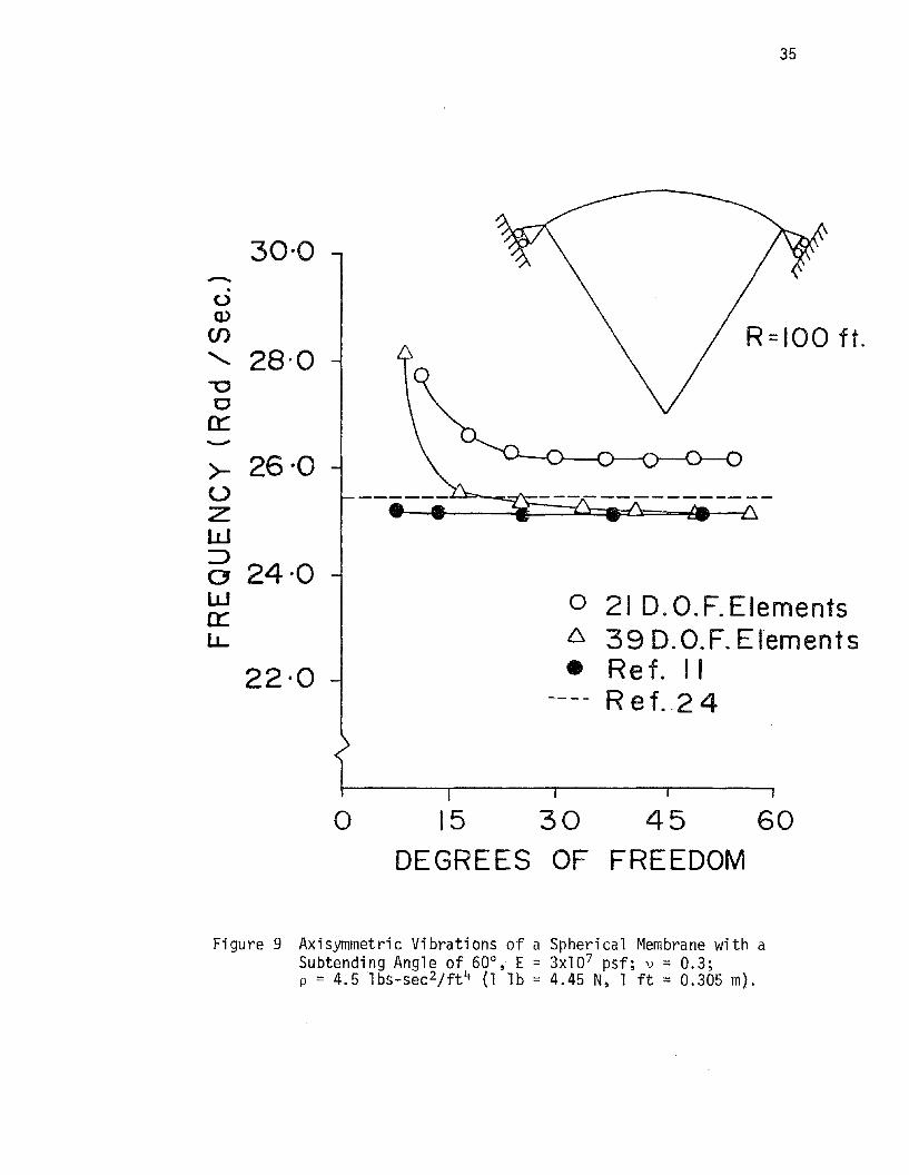
Figure 9 Axisymmetric Vibrations of a Spherical Membrane with aSubtending Angle of 60o~ E = 3xl07 psf; v = 0.3;p = 4.5 lbs-sec 2/ft 4 (1 lb = 4.45 N~ 1 ft = 0.305 m).

TABLE 3 - Natural Frequencies of Axisymmetric
Modes of a Spherical Cap
--
NATURAL FREQUENCY IN RADjSEC
Mode No Lower value Upper valueKraus (24) Present Kraus (24) Present
(1) (2) (3 ) (4) (5)
1 25.44 25.15 210.4 197.8
2 25.70 25.62 381.4 357.2
3 25.77 25.73 551.7 515.2
4 25.79 25.78 721.9 674.2
5 25.80 25.81 892.2 835.5
36

37
is very close to and approaches a limiting value of IE/p/R. Five pairs
of the natural frequency corresponding to the first five values of ~ or
the first five pair of modes are presented in Table 3. For each pair of
modes,the distribution for the normal deflection w is the same but the
distribution for the meridional displacement u is different.
When the present elements are used to solve the problem, only a small
segment of the shell with a subtending angle of 5° at the apex was analyzed
and both types of elements were used. The results for the natural frequen
cy for the lowest axisymmetric mode are plotted against the number of
d.o.f.'s using both types of elements. The converged values were obtained
as 26.15 and 25.15 rad/sec. using the 21 and 39 d.o.f. elements, respec
tively. The alternative analytical solution given by Kraus (24) yields
a value of 25.44 rad/sec. The results by using the quadrilateral membrane
elements by Gran and Yang (11) were also plotted in Fig. 9, with a converg
ed value of 25.15 rad/sec. The converged result obtained by using 39 d.o.f.
triangular element is in good agreement with that obtained in Ref. 11.
The 39 d.o.f. element was thus used to obtain the natural frequencies
corresponding to the first five pair of modes. The first five pairs of
natural frequencies obtained using 19 such triangular elements (81 d.o.f.)
are also given in Table 3. Agreement between the analytical and the pre
sent numerical results is good.
(ii) First Eccentric Frequency of a Fixed Based Cooling Tower -- The
same fixed-base cooling tower analyzed in Table 2 was examined using the
two types of triangular membrane elements. One half of the shell is
modeled by using five different meshes (lxl, 2x2, 3x3, 4x4, and 5x5) for
the 21 d.o.f. elements and four different meshes (lx2, 2x2, 2x3, and 3x3)

5.0
-;4.4, \00
N
~3. 8 ~ \6
•A
ZW::>aw3.20::lJ..
9 D.O.F. NASTRAN Membrane Elements21 D.O.F.' Triangular Elements39D.O.F.' TriangularE lements28 D.O.F.' Quadrilateral Elements ( II)/2 D.O.F NASTRAN Membrane Elements (II)
a- • ::0 * .:.it.-{
o 75 150 225
DEGREES OF FREEDOM300
Figure 10 First Eccentric Natural Frequency of a Fixed Base Hyperbolic CoolingTower Using the Two Types of Triangular r"lembrane Elements. w
co
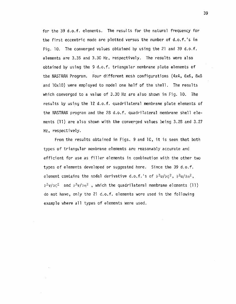
for the 39 d.o.f. elements. The results for the natural frequency for
the first eccentric mode are plotted versus the number of d.o.f. 's in
Fig. 10. The converged values obtained by using the 21 and 39 d.o.f.
elements are 3.35 and 3.30 Hz, respectively. The results were also
obtained by using the 9 d.o.f. triangular membrane plate elements of
the NASTRAN Program. Four different mesh configurations (4x4, 6x6, 8x8
and 10xlO) were employed to model one half of the shell. The results
which converged to a value of 3.30 Hz are also shown in Fig. 10. The
results by using the 12 d.o.f. quadrilateral membrane plate elements of
the NASTRAN program and the 28 d.o.f. quadrilateral membrane shell ele
ments (11) are also shown with the converged values being 3.28 and 3.27
Hz, respectively.
From the results obtained in Figs. 9 and 10, it is seen that both
types of triangular membrane elements are reasonably accurate and
efficient for use as filler elements in combination with the other two
types of elements developed or suggested here. Since the 39 d.o.f.
element contains the nodal derivative d.o.f.ls of 32U/3~2, 32u/3n2,
3 2V/3s2 and 32v/3n 2 , which the quadrilateral membrane elements (11)
do not have, only the 21 d.o.f. elements were used in the following
example where all types of elements were used.
39

40
CHAPTER 2
THREE ECCENTRIC FREQUENCIES OF A COLUMN-SUPPORTEDCOOLING TOWER USING THE WHOLE SET OF ELEMENTS
The cooling tower considered is defined by the following parameters:
radius at the base of the shell = 182.25 ft. (55.58 m); radius at the
throat = 116.5 ft. (35.5 m); radius at the top = 123 ft. (37.49 m);
height of the shell excluding the columns = 449.75 ft. (137.08 m); height
from the throat to the top of the shell 98.89 ft. (30.14 m); and thickness
= 12 in. (0.305 m); modulus of elasticity = 4xl06 psi (27.59 GN/m2 )
Poisson's ratio = 0.167; mass density = 0.225xlO- 3 lbs-sec 2/in4 (2.406
xl03 kg/m 3 ). The tower has 88 columns, each with the length of 41 ft.
(12.5 m) and cross section of 24 in (0.61 m) by 52 in. (1.32 m) in the
radial and circumferential directions, respectively. Each column inclines
with the meridional line at an angle of + 19°.
The modeling using the combination of the five types of elements is
shown in Fig. 1. Only a quadrant of the cooling tower is modeled and
the meshes for the five types of elements are shown in the figure.
The number of d.o.f.'s retained depends upon the boundary conditions
which are dictated by the mode shapes considered. In this example, the'
three fundamental eccentric modes were considered. It had been shown
that only these three modes are dominant in the earthquake response
behavior of a cooling tower (29,7,9,10). For such modes, the model shown
in Fig. 1 resulted in 412 d.D.f.'s. It is noted that if the general
shell elements were used to model the entire shell height, a total of

41
641 d.o.f.1s would have to be used. Both lumped mass and consistent mass
matrices were used. The results for the natural frequencies are given in
Table 4.
This example was analyzed previously by Gould, Sen and Suryoutomo (7)
using 14 doubly curved rotational shell elements and a column equivalent
rotational shell element. It was also analyzed by Basu and Gould (8) using
11 doubly curved rotational shell elements and a modified open-type column
equivalent rotational shell element. Both sets of results are shown in
Table 4. It is seen that the agreements between the four sets of results
are quite good except for that of the second eccentric mode using lumped
mass model.

TABLE 4.-- Three Eccentric Natural Frequencies of a Column SupportedCooling Tower.
NATURAL FREQUENCY IN. HERTZSLongitu- Circum-dinal ferential Goul d, Basu and Consistent LumpedNode ~1ode Sen & Gould ~1ass MassNumber Number Suryoutomo (Ref. 8)
m n (Ref. 7)(1) (2) (3) (4) (5) (6 )
1 2.296 2.336 2.333 2.2841 2 3.889 4.119 4.156 3.476
3 7.730 7.056 6.952 6.885
42

43
CHAPTER 3
STATIC ANALYSIS OF A FIXED BASECOOLING TOWER DUE TO WIND LOAD
Wind loading is the most significant environmental loading to which
a cooling tower is subjected to in its life span. Failure of the cooling
towers at Ferrybridge (1) and Ardeer (2) led to various research programs
towards the understanding of the nature of the wind loading (acting on
the cooling tower) itself and the resulting structural response of the
cooling towers. Billington and Abel (34) gave a reivew of the state-of
the-art of the design of the cooling towers subjected to wind loads. At
present, the wind loading is essentially assumed to be quasi-static and
is given by the following expression (35)
(30)
where
p = effective velocity pressure in psf at height Z feet
above the ground level;
KZ = an exposure factor which determines the vertical profile
of the wind due to the boundary layer effects of the
ground and depends upon the terrain roughness;
G = gust response factor to take into account the dynamic
response of the structure to turbulence;
Cp(8) = a coefficient for the circumferential distribution of
the wind pressure and is determined from the test results; and

44
2Q30 = 0.00256 Vf30
is the basic velocity pressure in psf at 30 feet (9.15 m) above ground
level obtained from the basic wind speed.
Abel and Billington (34) described these factors in great detail
along with the methods to obtain them.
Although the wind loads are assumed to be quasi-static in the design,
in reality, however, these loads are dynamic in nature. Furthermore,
they are highly random in both time as well as in space. For proper
understanding of the response of the cooling towers for the design pur
poses, the wind loads must be represented as accurately as possible and
the theory of random vibrations must be used to account for the randomness
of the wind loads.
For a given wind velocity Va' the wind load effect Pw can be expres
sed as
where W = static wind effect due to mean wind velocity V; andS
WD= dynamic wind effect due to the fluctuating component
V-V.o
(31)
Based on the pressure distributions obtained directly from experi-
mental measurements made on a full scale tower at Martinis Creek, Pa.,
a procedure to establish the level and distribution of the design
dynamic wind pressure loading over a cooling tower, was given by
Sollenberger, Scanlan and Billington (36).
Dynamic responses of the structure due to the fluctuating component
were determined from a statistical response analysis (37, 38, 39) and

45
from a deterministic time history response analysis (36, 40, 41). Such
responses have also been studied by measuring aeroelastic models in
wind tunnels (42, 43) and by measuring a full scale prototype (43).
The static response of the cooling tower due to the mean wind velo
city can be determined by analyzing the cooling tower subjected to a basic
pressure gi ven by Eq. 30 wi th G = 1. In thi s study, the static response
of a cooling tower subjected to a given pressure distribution is deter-
mined. The cooling tower under consideration is the same as that analyzed
for natural frequencies in Table 2. This tower was previously analyzed
by Albasiny and lvlartin (44) using finite difference method and by Chan
and Firmin (45) using rotational-type shell finite element of the SABA
family. Gould and Sen (46) developed and used a refined mixed method
rotational type shell element to study the static response due to the
wind loads. In all the above studies, the circumferential distribution
of the pressure coefficient was assumed to be given by the Batch and
Hopley distribution (44). This distribution, including a 0.5 internal
suction, is given by
C (8) = -1.524 cos (1.89 e)p
= 0.69 sin [3.61 (9-47.6)J
for 00 < 8 < 47.6
for 47.6 < 8 < 1000 (32)
= -0.21 for 1000 < 8 < 1800
The distribution is shown in Fig. 11. In all the above studies the pres-
sure distribution was approximately represented by a ten term Fourier
Cosine series. For the present 48 d.o.f. general shell element, such a
decomposition is not necessary.
The vertical profile of the wind velocity is assumed to be constant
throughout the shell height (KZ = 1) and the value of q(=~pV2) is assumed

46
-1.5
-1.2
-0.9
-0.6
-NN'>CL -0.3,-0.0
J. 0.0
II
a.U
0.3
0.6
0.9
Batch a Hopley Distribution( With Internal Suction)
135 1808 (DEGREES)
Figure 11 Pressure Distribution Around the Circumference.(With Internal Suction Cp = 0.5).

47
to be 1 psf corresponding to V = 19.76 MPH.
Three different mesh configurations using the present 48 d.o.f.
general shell elements (4x4~ 5x5, and 6x6) were used to model one half
of the shell. Since the wind loading was assumed to be symmetric, it
suffices to model only one half of the shell. But if the pressure distri-
bution is not symmetric, as may be the case on an actual cooling tower,
the entire shell has to be modeled. In each of the meshes employed, the
elements at the base of the tower were of a height 1.8% of that of the
cooling tower. Elements of such a small shell height were necessary to
properly capture the abrupt variation of the meridional moment at the
base. The topmost elements in all the meshes were of a height 18.2% of
the shell height. Each element subtended equal angle in the circumferen
tial direction. The pressure loads were converted into the nodal loads
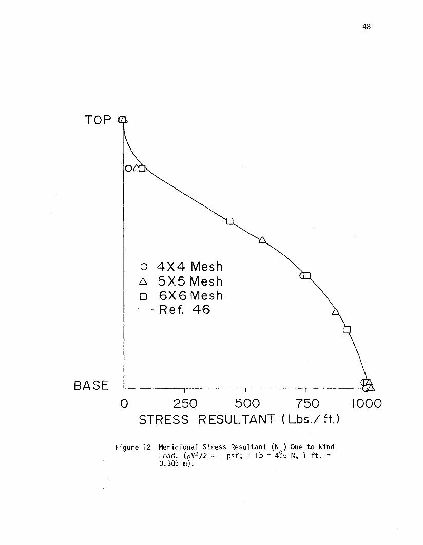
using consistent load vector. The results for the maximum meridional
stress resultant N¢ at e = 0° as obtained in the present analysis for
three meshes are given in Fig. 12. It should be mentioned that the
meridional stress resultant should be determined as accurately as possible
because the amount of steel reinforcement in the shell is dependent upon
this resultant. Fig. 13 gives the variation of the meridional bending
moment along the shell height. The bending moment is negligible through
out the shell height except for a narrow zone at the base. In both figures~
the results obtained by Gould and Sen (46) using a total of 19 rotational
type shell elements are also shown. Excellent agreement between the two
sets of results is seen.
Variation of the maximum radial displacement at e = 0° along the
shell height is given in Fig. 14. Results obtained by Chan and Firmin
(45) are also shown. These results are obtained for a shell thickness
TOP
BASE
48
o 4X4 Mesh6 5X5 Mesho 6X6Mesh- Ref. 46
a 250 500 750 1000STRESS R ESULTANT ( Lbs./ ft,)
Figure 12 Meridional Stress Resultant (N~) Due to WindLoad. (pV 2 j2 = 1 psf; 1 lb = 4.5 N, 1 ft. =0.305 m).

49
o 4 X 4 Mesh6 5X5 Mesho 6X6 Mesh-Ref. 46
r-~~~===t=~~;:::===:::;=====:;===....f=\---'-\.---,0-
-20 -10 0 10 20 30 40 50BENDING MOMENT (Lb.-ft. 1ft.)
Figure 13 Meridional Bending Moment (M~) Due to Wind Load(pV 2j2 = 1 psf; 1 lb. = 4.5N, 1 ft. = O.305m).

50
TOP
BASE
o 4X 4 Mesh6 5X5Mesho 6X6Mesh
Ref. 45
o
O. I. 2. 3. 4. 5.DE FLECTION (Ft.X 103 )
Figure 14 Radial Deflection at e = a Due to Wind Load.(pV 2/2 = 1 psf; thickness = 7 in.; 1 lb. =4.5N, 1 ft. = 0.305m.)

1000
I~- I \ -6 X 6 Mesh+-='+- 600""-u).0-I
---~ 200k V ~Nez«
~ -200J 30\~O/ 120 150 180e (DEGREES)
(f)
wn::(f)(f) -600wn::~(f)
-1000
Figure 15 Distribution of Membrane Stress Resultants N~ and Ne
atthe Shell Base Due to Wind Load (pV2/2 = 1 psf, 1 10 =4.5 N; 1 ft = 0.305 m).
tTl.......

52
of 7 in. (17.78 cm) rather than the shell thickness of 5 in. used in the deter
mination of the stresses. Once again excellent agreement is seen.
Figure 15 shows the variation of the membrane stress resultants in
the circumferential direction at the base of the shell obtained using
6x6 mesh for half of the shell. This distribution is quite similar to
the pressure distribution shown in Fig. 11. The maximum tensile stress
which occurs at the windward meridian (e = 0°) is larger than the maximum.
compressive stress occurring at about 70° from the windward meridian.
From the above results, it can be concluded that the response of
the cooling tower can be accurately predicted using the present develop
ments if the wind loads are assumed as quasi-static and known. Although
the results are obtained for a pressure distribution which is symmetric
about the direction of wind and is uniform along the shell height, the
results for non-symmetric and non-uniform pressure loads can be determined
just the same.
53
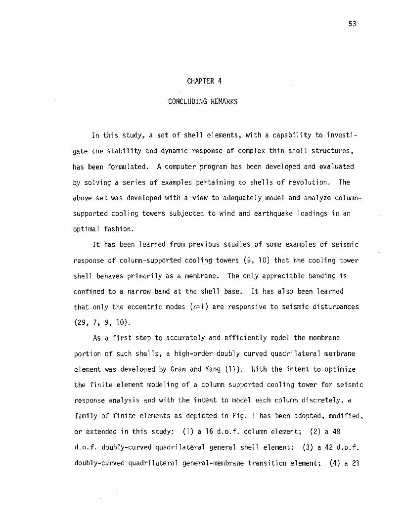
CHAPTER 4
CONCLUDING REMARKS
In this study, a set of shell elements, with a capability to investi
gate the stability and dynamic response of complex thin shell structures,
has been formulated. A computer program has been developed and evaluated
by solving a series of examples pertaining to shells of revolution. The
above set was developed with a view to adequately model and analyze column
supported cooling towers subjected to wind and earthquake loadings in an
optimal fashion.
It has been learned from previous studies of some examples of seismic
response of column-supported cooling towers (9, 10) that the cooling tower
shell behaves primarily as a membrane. The only appreciable bending is
confined to a narrow band at the shell base. It has also been learned
that only the eccentric modes (n=l) are responsive to seismic disturbances
(29, 7, 9, 10).
As a first step to accurately and efficiently model the membrane
portion of such shells, a high-order doubly curved quadrilateral membrane
element was developed by Gran and Yang (11). Hith the intent to optimize
the finite element modeling of a column supported cooling tower for seismic
response analysis and with the intent to model each column discretely, a
family of finite elements as depicted in Fig. 1 has been adopted, modified,
or extended in this study: (1) a 16 d.o.f. column element; (2) a 48
d.o.f. doubly-curved quadrilateral general shell element: (3) a 42 d.o.f.
doubly-curved quadrilateral general-membrane transition element; (4) a 21

54
d.o.f. and a 39 d.o.f. doubly-curved triangular membrane filler element;
and (5) a 28 d.o.f. doubly-curved quadrilateral membrane element.
Element (1) is a 3-D variation of that of Ref. 13. Element (2) is
the one that was developed in Ref. 12 but with some difference in formu
lative procedures and with extensive application in this study to the
cooling tower analysis of buckling and vibration with initial stresses.
Element (3) is developed here. Elements (4) are the modified version of
those in Refs. 30 and 31 to fit the present need. Element (5) is adopted
from Ref. 11. Various examples have been demonstrated to evaluate an
individual type, a few combined types, and the whole set of elements and
the results are all quite good.
During a seismic disturbance, the regions containing the joints between
the columns and the base of the shell are vulnerable and it is highly de
sirable that the state of the stress distributions in these regions at
certain critical moments be studied and understood. It is also highly
desirable that material nonlinearity be considered in such a study. For
these purposes, the modeling of the base regions by using the discrete
column elements and quadrilateral general shell elements is suggested.
Research is now being carried out to study the nonlinear stress
distribution in a cooling tower subjected to seismic disturbances. The
effect of wind loads is also being studied. As a first step,the response
of the cooling tower due to the mean wind velocity has already been
studied and the results obtained are in excellent agreement with the
alternatively available results. The cooling tower response due to the
fluctuating velocity component will be studied in collaboration with
Professor Y.K. Lin using the theory of random vibrations. For wind
disturbances, the breathing modes such as n = 6 are also important. For

55
breathing modes with circumferential wave numbers equal to 4 or 5, or
above, the shell no longer behaves primarily as a membrane. The present
general shell elements must be used through the shell structure.
In addition to the adequate representation of the structural proper
ties (mass, stiffness and damping) of the cooling tower, the characteris
tics of the wind loading (spectral characteristics of the gust, spatial
distribution and correlation of pressure over the tower surface etc.) must
be accurately known. Efforts are now underway, under the direction of
Professor Anshel L. Schiff to determine the wind loads by performing
measurements on a full scale cooling tower. The dynamic response will
also be measured to corroborate the results with those obtained theoreti
cally.

56
REFERENCES
1. "Report of the Committee of Inquiry into the Collapse of the CoolingTower at Ferrybridge, Monday, Nov. 1, 1965," Central ElectricityGenerating Board, Her Majesty·s Stationary Office, London, England,1966.
2. Miller, K.A.G. (chairman), "Report of the Committee of Inquiry intothe Collapse of the Cooling Tower at Ardeer Nylon ~Jorks, Ayrshireon Thursday, 27th September 1973," Imperical Chemical IndustriesLimited, Petrochemicals Division, available from Engineering ServicesDepartment, Imperical Chemical House, Mil1bank, London SWIP 3JF, nodate.
3. Carter, R.L., Robinson, A.R., and Schnobrich, W.C., "Free Vibrationof Hyperbo1ida1 Shells of Revolution," Journal of the EngineeringMechanics Division, ASCE, Vol. 95, No. EM5, Proc. Paper 6808, Oct.1969, pp. 1033-1052.
4. Hashish, M.G., and Abu-Sitta, S.H., "Free Vibration of HyperbolicCooling Towers," Journal of the Engineerin
At1echanics Division,
ASCE, Vol. 97, No. EM2, Proc. Paper 8037, pr., 1971, pp. 253-269.
5. Sen, S.K., and Gould, P.L., "Free Vibration of Shells of RevolutionUsing FEM," Journal of the Engineering ~1echanics Division, ASCE,Vol. 100, No. EM2, Proc. Paper 10488, April, 1974, pp. 283-303.
6. Nelson, R.L., "Free Vibration Analysis of Cooling Towers," Shockand Vibration Digest, Vol. 12, No. 12, Dec., 1980, pp. 15-24.
7. Gould, P.L., Sen, S.K., and Suryoutomo, H., "Dynamic Analysis ofColumn-Supported Hyperboloidal Shells," Earth~uake Engineering andStructural Dynamics, Vol. 2, 1974, pp. 269-27 .
8. Basu, P.K.,and Gould, P.L., IIFinite Element Discretization of OpenType Axisymmetric Elements," International Journal for NumericalMethods in Engineering, Vol. 14, No.2, 1979, pp. 159-178.
9. Gran, C.S., and Yang, T.Y., IINASTRAN AND SAP IV Applications on theSeismic Response of Column-Supported Cooling Towers," Journal ofComputers and Structures, Vol. 8, No.6, June, 1978, pp. 761-768.
10. Gran, C.S., and Yang, T.Y .., "Refined Analysis of the Seismic Responseof Column Suported Cooling Towers," Journal of Co~puters andStructures, Vol. 11, No.3, 1980, pp. 225-231.
11. Gran, C.S., and Yang, LY .., "Doubly Curved Membrane Shell FiniteElement," Journal of the Engineering MechanicsDivision, ASCE, Vol.105, No. EM4, Proc. Paper 14741, Aug., 1979, pp. 567~584.

57
12. Fonder, G.A., IIStudies in Doubly Curved Elements for Shells ofRevolution,1I Finite Elements for Thin Shells and Curved Members,D.G. Ashwell and R.H. Gallagher, ed., John Wiley and Sons, Inc.,New York, N.Y., 1976, pp. 113-129.
13. Yang, T.Y., and Sun, C.T., "Finite Elements for the Vibration ofFramed Shear Walls,1I Journal of Sound and Vibration, Vol. 27,No.3, 1973, pp. 297-311.
14. Ashwell, D.G., and Gallagher, R.H., ed., Finite Elements for ThinShells and Curved Members, John Wiley and Sons, Inc., New York,N.Y., 1976.
15. Gallagher, R.H., liThe Development and Evaluation of Matrix Methodsfor Thin Shell Struct.ural Analysis,1I Re~ortNo. 8500-902011,Bell Aerosystems, Buffalo, N.Y., June 1 66.
16. Cantin, G., and Clough, R.W., IIA Curved Cylindrical-Shell FiniteElement,1I AIAA Journal, American Institute of Aeronautics andAstronautics, Vol. 6, No.6, June 1968, pp. 1057-1062.
17. Bogner, F.K., Fox, R.L. and Schmit, L.A. ,Jr., "A Cylindrical ShellDiscrete Element," AIAA Journal, American Institute of Aeronauticsand Astronautics, Vol. 5, No.4, Apr., 1967, pp. 745-750.
18. Greene, B.L, Jones, R.E., McLay, R.~~., and Strome, D.R., IIDynamicAnalysis of Shells Using Doubly-Curved Finite Elements," Proceedingsof the 2nd Conference on Matrix Methods in Structural Mechanlcs,Air Force Flight Dynamics Laboratory, TR-68-150, Dayton, Ohio, Dec.1969, pp. 185-212.
19. Yang, T. Y., "High Order Rectangular Shallow Shell Finite Element,lIJournal of the EngineerinfiMechaniCSDivision, ASCE, Vol. 99, No.EMl, Proc. Paper 9519, Fe . 1973, pp. 157-181.
20. Novozhilov, V.V., Thin Shell Theory, 2nd ed., Wolters-NoordhoffPublishing, Groningen, The ~etherlands, 1970, pp. 22-23.
21. Gallagher, R.H., and Yang, T.Y., "Elastic Instability Predictionsfor Doubly-Curved Shells,1I Proceedings of the 2nd Conference onMatrix Methods in Structural Mechanics, TR-68-150, Dec. 1969,Air Force Flight Dynamics Lab., Dayton, Ohio, Dec., 1969,pp. 711-739.
22. Larsen, P., "Large Displacement Analysis of Shells of RevolutionIncluding Creep, Plasticity and Viscoelasticty," thesis presentedto the University of California at Berkeley, Calif., in 1972, inpartial fulfillment of the requirements for the degree of Doctorof Philosophy.
23. Fonder, G.A., and Clough, R.W., IIExplicitAddition of Rigid-BodyMotions in Curved Finite Elements,lI AIAA Journal, American Instituteof Aeronautics and Astronautics, Vol. 11, No.3, Mar., 1973,pp. 305-312.

58
24. Kraus, H., Thin Elastic Shells, John Wiley and Sons, Inc., New York,N.Y., 1967, pp. 136-140, 316-319.
25. Kalnins, A., "Effect of Bending on Vibrations of Spherical Shells,"The Journal of the Acoustical Society of America, Vol. 36, No.1,Jan., 1966, pp. 74-81.
26. Zarghamee, M.S., and Robinson, A.R., "A Numerical Method for Analysisof Free Vibration of Spherical Shells," AIAA Journal, AmericanInstitute of Aeronautics and Astronautics, Vol. 5, No.7, July 1967,pp. 1256-1261.
27. Brush, D.O., and Almroth, B.a., Buckling of Bars, Plates and Shells,McGraw-Hill Book Company, 1975, pp. 167-168.
28. Deb Nath, J.M., IIFree Vibration, Stability and Nonclassical Modesof Cooling Tower She11s," Journal of Sound and Vibration, Vol. 33,No.1, 1974, pp. 79-101.
29. Abu-Sitta, S.H. and Davenport, A.G.,.IIEarthquake Design of CoolingTowers," Journal of the Structural Division, ASCE, Vol. 96, No. ST9,Proc. Paper 7524, Sept., 1970, pp. 1889-1902.
30. Cowper, G.R., Lindberg, G.M., and Olson, M.D., "A Shallow ShellFinite Element of Triangular Shape," International Journal ofSolids and Structures, Vol. 6, 1970, pp. 1133-1156.
31. Thomas, G.R., and Gallagher, R.H., IIA Triangular Shell FiniteElement: Linear Analysis," NASA C.R. 2482, July, 1975.
32. Dawe, D.J., "High-Order Triangular Finite Element for Shell Analysis,"International Journal of Solids and Structures, Vol. 6,1975,pp. 1097-1110.
33. Strang, G., and Fix, G.J., An Analysis of the Finite Element Method,Prentice Hall, 1973, pp. 156-163.
34. Billington, D.P., and Abel, J.F., IIDesign of Cooling Towers forWind," Proceedings of the Speciality Conference on Methods ofStructural Analysis, University of Wisconsin-Madison, Aug., 22-25,1976, pp. 242-267.
35. IIReinforced Concrete Cooling Tower Shells: Practice and Commentary,"Report of the ACI-ASCE Committee 334, February, 1976.
36. Sollenberger, N.J., Scanlan, R.H., and Billington, D.P., IIWindLoading and Response of Cooling Towers,1I Journal of the StructuralDivision, ASCE, Vol. 106, No. ST3, March 1980, pp. 601-621.
37. Abu-sitta, S.H., and Hashish, M.G., "Dynamic Wind Stresses inHyperbolic Cooling Towers,1I Journal Of the Structural Division,ASCE, Vol. 99, No. ST9, Sept., 1973,pp. 1823-1835.

59
38. Hashish, M.G., and Abu-sitta, S.H., "Response of Hyperbolic CoolingTower to Turbulent Wind," Journal of the Structural Division, ASCE,Vol. 100, No. ST5, May, 1974, pp. 1037-1051.
39. Singh, M.P., and Gupta, A.K., "Gust Factors for Hyperbolic CoolingTowers," Journal of the Structural Division, ASCE, Vol. 102,No. ST2, Feb., 1976, pp. 371-386.
40. Steinmetz, R.L., Billington, D.P., and Abel, J.F., "HyperbolicCooling Tower Dynamic Response to Wind," Journal of the StructuralDivision, ASCE, Vol. 104, No. ST1, Jan., 1978, pp. 35-53.
41. Basu, P.K., and Gould, P.L., "Cooling Towers Using t~easured WindData," Journal of the Structural Division," ASCE, Vol. 106, No. ST3,March 1980, pp. 579-600.
42. Armitt, J., "Wind Loading on Cooling Towers," Journal of theStructural Division, ASCE, Vol. 106, No. ST3, March 1980,pp. 623-641.
43. Ni emann, H. - J., and Ruhwedel, J., "Full-Scale and Model Tests onWind-Induced, Static and Dynamic Stresses in Cooling Tower Shells,"Engineering Structures, Vol. 2, April 1980, pp. 81-89.
44. Albasiny, LL., and Martin, D.W., "Bending and Membrane Equilibriumin Cooling Towers," JournaloftheEngine~ring Mechanics Division,ASCE. Vol. 93, No. EM3, June 1967, pp. 1-17.
45. Chan, A.S.L., and Firmin, A., "The Analysis of Cooling Towers bythe Matrix Finite Element Method. Part I: Small Displacements,"The Aeronautical Journal of the Royal Aeronautical Society, Vol.74, No. 10, London, England, Oct. 1970, pp. 826-835.
46. Gould, P.L., and Sen, S.K., "Refined Mixed Method Finite Elementsfor Shells of Revolution"· Proceedings of the Third Conference onMatrix Methods in Structural Mechanics, Air Force Flight DynamicsLab., TR-71-l60, Dayton Ohio, Dec. 1973, pp. 397-421.