Embed Size (px)
Citation preview

1
CRITICAL UTILITY DESIGN AND MAINTENANCE
Gaston Loo Maintenance Lead MSD SINGAPORE
ASEAN Life Sciences Conference and Exhibition - 2013
2
• Type of utilities system • Regulatory requirement • Design approach
– Design principle and strategic – GEP – System boundaries
• Maintenance plan – Rouging – Filter integrity testing – Contamination / microbial control
• Industry trend - PAT
Agenda

3
Critical utilities system – Gas system – Pure steam – Water system
Non-critical utilities system – Chilled water – Plant steam – Instrument air – Potable water
Type of utilities system
4
Critical utilities system
• Direct impact system (process system) – Contact the product – Direct impact product quality – Contact materials that ultimately become part of product
• Depend on process, can be raw material, component or
process aid (excipient)
• Application example: – N2 for vessel blanketing – Pure steam SIP – WFI for compounding
Definition

5
Critical utilities system
Equipment that use critical utility:
– Blow-fill-seal (BFS) packaging machines – Compounding system – Filling line – Freeze-drying (lyophilization) – Part washer – Autoclave – SIP skid
6
Gas system
Critical utilities system
Nitrogen – Storage tank – Distribution loop
Sterile air (filtered air) – Generation (compressed air)
• Oil free type – Distribution loop
• Buffer tank • Air dryer • 0.2μ filter

7
Pure steam
Critical utilities system
Pure steam – Generation – Distribution loop
Key feature
– Feed water from PFW – Use plant steam for distillation process
- Removal of endotoxins and other impurities via
multiple separation stages - For process sterilization purpose
8
Critical Utilities System
Water For Injection (WFI) – Generation
• Feed water from PFW – Storage and distribution
Water system Purified water system (PFW) – Generation – Storage and distribution

9
Storage and Distribution System Key components
• Tanks • Pumps • Heat exchangers • Valves • Sample Valves • Instrumentation
• What’s critical? • Location
10
Schematic
PFW Generation
UNIT
MULTIMEDIA FILTER
DOSING HYPOCHLORITE
FILTER CARBON
FILTERS CARTRIDGE
TO PURIFIED WATER TANK
HEAT
HEAT EXCHANGERS
COOL
REVERSE OSMOSIS TWIN PASS
CONTINUOUS DEIONISATION
STORAGE TANK PUMP
RETURN FROM PURIFIED
WATER TANK
UNIT
SOFT WATER INLET
FINAL FILTER

11
PFW Generation
• The softened and chlorinated water is fed to a multi-media filter unit (MMF).
• Remove particulate present within the feed water supply.
• After filtration, the water flows to a break tank for storage.
Multi-media filter
12
Break tank PFW Generation
• Feeds into break tank – The MMF water – Water re-circulated back from
final filter
• The It consist of – spray ball – heated vent filter – bursting disc – level sensors

13
PFW Generation
The activated carbon filter removes – light weight organics – any residual chlorine
Daily backwash cycle (Auto or manual)
Activated carbon filter
14
Reverse Osmosis (RO) unit PFW Generation
To remove up to 90 - 98% of inorganic ions together with all large contaminants and organic molecules contained in the feed water.
A twin pass RO unit protect
the system from bacteria and pyrogens.
15
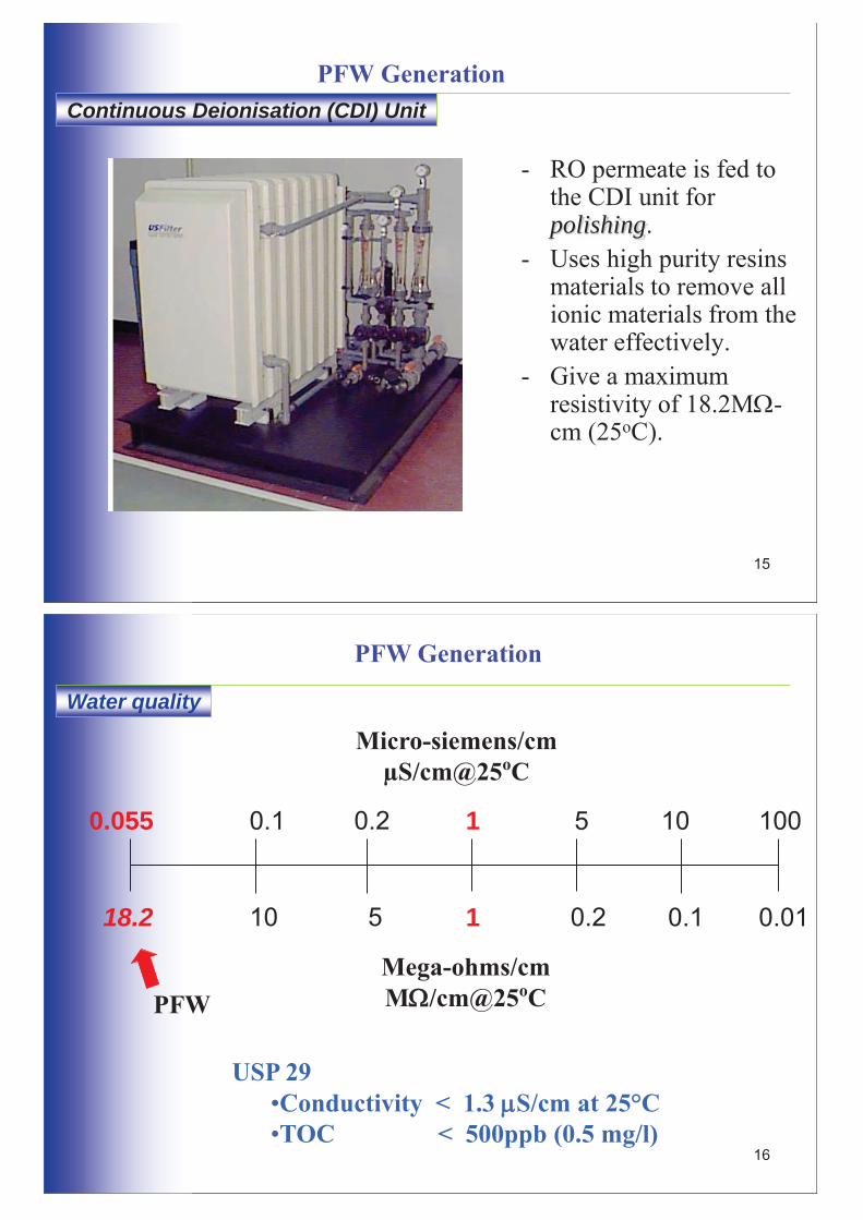
PFW Generation
- RO permeate is fed to the CDI unit for polishing.
- Uses high purity resins materials to remove all ionic materials from the water effectively.
- Give a maximum resistivity of 18.2M -cm (25oC).
Continuous Deionisation (CDI) Unit
16
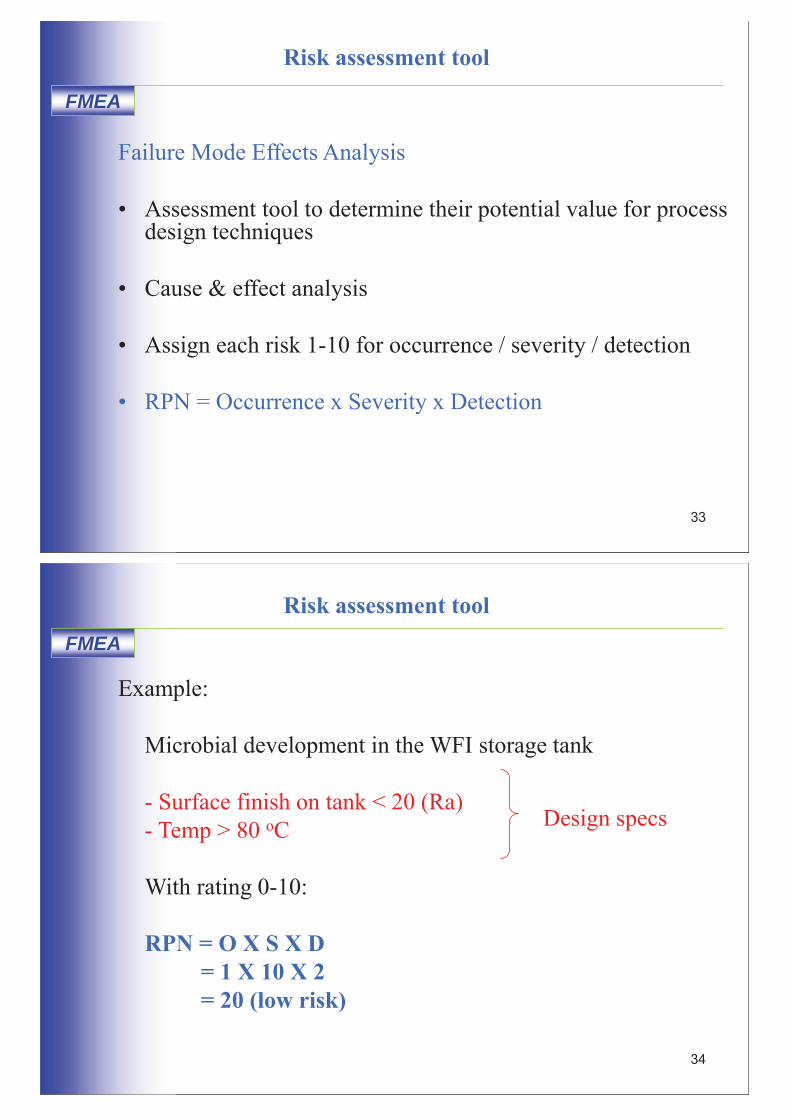
Water quality
PFW Generation
1
1 5 10 0.1 0.055 100 0.2
0.2 0.1 0.01 5 10 18.2
Micro-siemens/cm μS/cm@25oC
Mega-ohms/cm M /cm@25oC
USP 29 •Conductivity < 1.3 S/cm at 25°C •TOC < 500ppb (0.5 mg/l)
PFW

17
Conductivity of different water
PFW Generation
Pure water
Purified water
Drinking water
Brackish water
Sea water
Conductivity μS/cm 0.01 0. 1 1.0 10 100 1000 10000 100000
LOW MEDIUM HIGH
Resistivity MΩ/cm 100 10 1.0 0.1 0.02 0.001 0.0001 0.00001
18
PFW Generation
• The water is passed through 0.2 μm before entering into storage tank.
• Bioburden reduction • Removal of particulate
contamination down to 0.2 μm.
Final Filter
Microbio limits: - drinking water < 500 cfu/ml - PFW < 100 cfu/ml - WFI < 10 cfu/ml

19
• Type of utilities system • Regulatory requirement • Design approach
– Design principle and strategic – GEP – System boundaries
• Maintenance plan – Rouging – Filter integrity testing – Contamination / microbial control
• Industry trend - PAT
Agenda
20
What might a regulator want?
For people to understand the intent of regulations, and then
implement programs to meet that intent.

21
FDA
Regulatory requirement
FDA has recently focused attention on critical utilities. End users and their qualification and quality assurance personnel must demonstrate that the facility complies with 21 CFR 211.65(a) which states: “Equipment shall be constructed so that surfaces that contact components, in-process materials or drug products, shall not be reactive, additive, or absorptive so as to alter the safety, identity, strength, quality, or purity of the drug product beyond the official or other established requirements.”
22
PIC/S
Regulatory requirement
PIC/S is the abbreviation and logo used to describe both the - Pharmaceutical Inspection Convention (PIC) - Pharmaceutical Inspection Co-operation Scheme (PIC Scheme)
PIC Scheme PIC Scheme Convention An informal arrangement
A formal treaty
Has no legal status Has legal status
Between Health authorities Between countries
Exchange of information
Mutual recognition of inspections
The main differences between the PIC Scheme and PIC are :
operating together in parallel.

23
PIC/S
Regulatory requirement
• PIC/S develop guidance “The Aide-Memoire – Inspection
of Utilities” for GMP inspectors
• For training and preparation of inspection
• Checklist for critical utility on water, steam and gases
24
Standard
Regulatory requirement
Improved standard and guidelines such as - ASME Bioprocessing Equipment standard (BPE-2012) - ISPE Baseline@ Pharmaceutical Engineering Guides - International Standard ISO 8573 Compressed Air
have driven the quest of quality in pharmaceutical
industry.
• Vary of interpretation by different regulators

25
EMEA
Regulatory requirement
Reflection Paper on 5 March 2008 EP requirement for WFI be produced only by distillation Refer RO membranes as "bacterial fermenters" and production of WFI RO would not be “as safe as water prepared by distillation”
Mandatory for manufacture of all products shipped into the European Economic Area
EMEA reaffirms rejection of RO for WFI production in EEA
26
USP
Regulatory requirement
• Recognized and used in > 140 countries • Guide to produce medical products
• Specify standard for PFW and WFI
U.S. Pharmacopeia
Example: • Conductivity @ temperature (USP <645>) • TOC (USP <643>) • Bacteriological Purity Total Aerobic Count
(CFU/Ml)

27
• Type of utilities system • Regulatory requirement • Design approach
– Design principle and strategic – GEP – System boundaries
• Maintenance plan – Rouging – Filter integrity testing – Contamination / microbial control
• Industry trend - PAT
Agenda
28
GEP
Design approach
Design approach affect by following factors:
Factors
Critical Utility Design
Process
Budget
Timeline
Quality Validation
Safety & Environment
Automation
Feed Water Quality
Specification

29
Design and project workflow
Direct-impact systems only
Quality-critical requirements only
Design principle and strategic
30
GEP • Set the standard and specifies your requirements
• Document the functions you want
• Used as a live document up until the DQ is completed and
approved
• Traceability of PQ and OQ functionality testing (RTM)
• Part of procurement process e.g. tender document
URS
User requirement specification

31
Design phase
Engineering specification
FDS - Functional Design Specification HDS - Hardware Design Specification SDS - Software Design Specification
DQ - Design Qualification Owner
Vendor
32
GEP
Risk assessment
• Minimize project expenditures, streamline validation, and forgo unnecessary processes or mechanical design options
• Serve to qualify the use of certain system and component
attributes that affect cost and performance • Determine what operations of critical utilities classified as
critical and non-critical
• Determine the scope and extend of validation
Objective
33
GEP
Risk assessment tool
Failure Mode Effects Analysis • Assessment tool to determine their potential value for process
design techniques
• Cause & effect analysis
• Assign each risk 1-10 for occurrence / severity / detection
• RPN = Occurrence x Severity x Detection
FMEA
34
GEP
Risk assessment tool
Example: Microbial development in the WFI storage tank - Surface finish on tank < 20 (Ra) - Temp > 80 oC With rating 0-10: RPN = O X S X D = 1 X 10 X 2 = 20 (low risk)
FMEA
Design specs

35
FMEA form
Risk Assessment & FMEA Risk Assessment FMEA
Structured by System Quality Attributes (SQA)
Structured by process steps
Begins with identifying hazards to SQA’s
Begins with identification of potential failure modes
Controls are assessed based on design features and procedures
Controls are grouped as prevention and detection controls
Used to identify controls that must be incorporated into the user requirements
Used to identify and prioritize risks of a given process
Used to establish acceptance criteria for validation
36

37
Good Engineering Practice (GEP)
“I don’t know how to explain them, but I know them when I
see them.”
38
GEP
Apply to all critical utility from design to operation stage: • Projects
– design – construction – commissioning
• Standards & Practices – drawing control – equipment change management – documentation
• Operations – maintenance – calibration – safety and environmental
Scope
Good Engineering Practice (GEP)

39
General rule
Good Engineering Practice (GEP)
• Allow provision for future expansion • Utilities should be routed from plant room to process
area • Process utility systems are designed to satisfy the
requirement of facility • Meet regulatory requirements and expectations
pertaining to equipment • Drawing for utility systems must be approved and
updated.
40
Good Equipment Layout
Good Engineering Practice (GEP)
Keep design as simple as possible Ease of access for operation and maintenance
Follow process flow
Provide good spacing for equipment
Operators review equipment layout during design stage
Equipment and piping labeling

Good Engineering Practice (GEP)
System “Qualification Drawing” requirements: show the plant layout, with service connections and, as appropriate:
All isolating-, drain-, vent-, control-valves, and items served, complete with tag numbers where used. Any critical items, such as filters, outlets, sample points etc. The quantity, quality and direction of flow of the working fluid.
Component tagging Main components should be tagged or labelled, to ensure that there are unique references for items to use in:
Commissioning records Maintenance records SOP’s Asset registers
Good Equipment Layout
41
42
GEPs and EQ
System boundaries
URS
Engineering Specs
Design Details
EQ
SAT / Commissioning
FAT
GEP
GMP
Quality Critical Attributes

43
Design criteria
System boundaries
Utility quality
Use point criteria
System criteria
Re-evaluate system design boundaries and constraints
Detailed system design
- Product - Regulatory - Dosage form
- Pressure - Temp - Flow rate - Demand - Auto/manual
- Storage - Future capacity - Generation rate - Feed water Quality
43
44
Compressed air to sterile air
System boundaries
Sanitary sampling point
Galvanized piping
Sanitary valve
0.2 μm sterile filter
Critical
Non critical
SS piping

45
Critical utility design
Standard requirement
Basic requirement includes: – Eliminate dead legs where possible – Sanitary design for component – N2 seal storage tank or vent filter(0.2μm) – Piping material - SS316L – Orbital welding and inspection – Sampling point for distribution loop – Instruments for trending (TT / FT / PT) – Standby pump for water distribution loop – ISO/DIN type of gasket / seal e.g. PTFE, EPDM,
Viton® and Silicone
46
Why Stainless Steel 316L
L indicates low carbon – but note that the specification limits for 316 and 316 L overlap
316 C Mn Si P S Cr Mo Ni N
Min - - - 0 - 16.0 2.0 10.0 -
Max 0.08 2.0 0.75 0.045 0.03 18.0 3.0 14.0 0.10
316L
Min - - - - - 16.0 2.0 10.0 -
Max 0.03 2.0 0.75 0.045 0.03 18.0 3.0 14.0 0.10
SS 316L used when there is a danger of corrosion in the heat-affected zones of weldments

47
Why Stainless Steel 316L
Many reasons:
• Availability of tube and sheet material • Availability of valves and fittings • Corrosion resistance • Weldability
• ASTM A269 (unpolished ID and OD) and A270 (polished
ID and OD) • Tolerances are generally tighter for ASTM 270
48
Orbital Welding
• The standard approach is to use closed head orbital welding – Automated repeatable quality welds – Protection from oxidation on both sides by purge gas – Weld parameters (primary / background values of pulsed
welding current, primary / background pulse times and rpm), controlled by the power supply, which determines the surface travel speed of the tungsten electrode.
• Orbital welding provides precise control of the heat input into the weld results in better corrosion resistance than manual welding
• Ensure sample welds (coupon) are produced for all heat combinations.

49
Orbital Welding – test coupon
Test coupons that conform to the specification on the actual materials to be used before the start of the job
Others: - lines were labeled with the heat number of the tubing - date of welding - weld number on the ISO drawing - piping system number - weld log for future reference
50
Water system
Standard requirement
Air gap for drain point (min. 50mm)
Eliminate microbial contamination from common drain line
ASME 112.1.2: The minimum required air gap shall be twice the diameter of the effective opening

Dead Leg definitions
D
L
A dead leg is any area in a piping system where water can become stagnant and where water is not exchanged during flushing.
Bacteria in dead-end pipe lengths / crevices are protected from flushing and sanitization procedures and can recontaminate the piping system.
Zero deadleg valves were used to minimize deadlegs in critical areas of the piping system
Modern piping design limits the length of any dead-end pipe to 6 times the pipe’s diameter (even shorter dead legs are preferred).
This is the six diameter rule (6D).
51
Dead Leg guideline
As per ASME BPE 1997 : " For Bioprocessing systems, L/D of 2:1 is achievable with today's design technology for most valving and piping applications"
As per FDA - GUIDE TO INSPECTIONS OF HIGH PURITY WATER SYSTEMS: it defined dead-legs as not having an unused portion greater in length than six diameters of the unused pipe measured from the axis of the pipe in use.
D
L
If deadlegs exist in a system, some provision should be made for flushing them through routinely. 52

53
Case Study - Dead leg
IN
OUTLET
Dead leg section during normal
operation
Promotes microbial growth and formation
of bio-film
DRAIN
Affects performance of
carbon filter
Carbon filter manifold in operation
Carbon filter tank
54
Case Study - Dead leg
Dead leg section, collects ‘dirty’ backwash water
Drain
Carbon filter manifold during back-washing
IN
OUTLET
Carbon filter tank

55
After improvement
Outlet
Inlet
Drain
Carbon filter tank
Carbon filter manifold in operation
Case Study - Dead leg
Keep deadlegs between valves to minimum
56
After improvement
Outlet
Inlet
Drain
Keep dead legs between valves to minimum
Carbon filter tank
Case Study - Dead leg
Carbon filter manifold during back-washing

57
• Type of utilities system • Regulatory requirement • Design approach
– Design principle and strategic – GEP – System boundaries
• Maintenance plan – Rouging – Filter integrity testing – Contamination / microbial control
• Industry trend - PAT
Agenda
58
Maintenance challenge
• Maintenance always link to reliability / availability – 24hrs X 365 days
• Maintain the validated state
• Contamination / microbial control
• M

59
Rouging
• A form of surface corrosion – reddish / brownish
• Common problem in WFI / pure steam systems
• High temperatures and dissolved gases accelerate corrosion and formation of iron oxides
• Iron oxide can break away from SS surfaces and flow through the entire water system downstream
(migratory rouge)
60
Effect
Rouging
• Cr-oxide dominated passive-layer is changing to Fe-oxide enriched corrosion layer
• Influencing parameters: – Alloy quality – Surface treatment – WFI quality – Temperature – Exposition time – Gas content (type and quantity)

61
Example
Rouging
• Typically found in:
– Pump impellors and internal housing – Vessel spray balls – In-line filters and housings – Storage vessel surfaces (usually above water line) – PTFE surfaces e.g. tri-clamp gaskets and valve
diaphragms
62
Example
Rouging
Spray ball WFI storage tank
Pump impeller from WFI system
Pump volute from WFI system

63
Example
Rouging
Rouging on a PTFE tri-clamp gasket
Rouge discoloration found on a point of use
0.45 μm filter membrane
64
Example
Rouging
Rouge can be wiped off and can move throughout a system. The rouge layer consists of heavy-metal-oxides, preferably Fe-Oxides. The rouge-layer consists of particles of heavy-metal-oxides which can leave the surface based on stream conditions.
Wipe test of a production vessel Wipe test of a WFI pipe

65
Passivation
Rouging control
• Removal of rouging • Generate an oxide film that covers and protects the
surface of the SS surface by nitric acid or citric acid
• Recirculation through distribution loop (2 hrs) • Post passivation – PFW water flushing till pH 6 to 8
66
Before / After Derouging
before Derouging after Derouging

67
Monitoring
Rouging control
• Schedule inspection to check components in the loops for sign of rouge
• Establish baseline and identify possible problem area
• Establish SOP for derouging / repassivation process
• Routine sampling of water quality – Conductivity – TOC – Heavy metals – Nitrate
68
Filter integrity testing (FIT)
• Filter type: - Air / Gas filtration - Water filtration - Vent filtration for storage tank
• Purpose: - Sterile boundaries - Protect from contamination (bacteria retention) • Maintenance: - Routine schedule replacement - FIT (before and after)

69
Filter integrity testing
• What is FIT? A measure of the ability of a filter element to work as
designed through multiple cycles, is a sensitive process parameters that requires qualified testing
• Factors influencing FIT - Temperature - Upstream Volume - Wetting Agent
70
Filter integrity testing
Breaches may occur as a result of… • Factory defects • Shipping damage • Improper maintenance • Structural creep • Chemical degradation • Age
Breaches can occur in many locations… • Seals and O-rings • Membrane potting • Fibers (broken or
punctured)
Potential integrity breaches underscore the need for FIT

71
Type of FIT
- Water intrusion test (gas)
- Forward flow (water)
- Bubble point filter test
72
Water intrusion test (gas / vent)
For hydrophobic gas filters
WIT
The resistance to water flow is overcome by a specific pressure

73
• An integrity test measuring air diffusion • Measurement of diffusive (diffusional) flow of a gas
through a wetted filter. • Measured under pressure and evaluated by comparing
the results to a limit value.
Forward flow (water)
74
Contaminants in water
Dissolved inorganic Dissolved organics
Micro-organisms Particulate matter

75
Source of Contamination
Sources of Microbial Contamination
• Source supply water or feedwater • Unprotected Vents / unsealed tanks • Faulty air filters • Contaminated use points/sample points • Unsatisfactory drain air breaks • Replacement carbon/resin/sand • Contaminated chemical additions • Improper sampling
76
Contamination control
RO membrane cleaning
• Cleaning is activated by - fall in permeate - dramatic rise in permeate conductivity - rise in 1st pass differential pressure
• Acid clean - remove hardness scale and is effective in removing
iron precipitates.
• Alkaline clean - remove biological material, colloid, silica etc.

77
Contamination control
CDI cleaning
Cleaning removes debris, scale, and resin foulants from the module that can severely reduce performance It is very important to follow cleaning guidelines in the CDI O&M manual
- for cleaning to be effective - to avoid damaging the module
78
Microbial Control and Biofilms
There are a number of measures that control microbes:
1. Avoid or minimise dead legs 2. Continuous re-circulation of water 3. Avoid stagnant ambient temperature water 4. Allow for drainage of pipework 5. Use sanitary valves & suitable gaskets selection 6. Use suitable construction materials 7. Maintain system water temperature at > 70*C 8. Regular sanitation or sterilization 9. UV radiation 10. Air break for drains

79
Microbial Control
1. Continuous re-circulation of water 2. Avoid stagnant ambient temperature water 3. Allow for drainage of pipework and storage tanks 4. Use sanitary valves 5. Avoid or minimise dead legs
The above measures discourage bacteria from:
• Lingering longer and reproducing to larger numbers • Settling to establish biofilms • Good drainage of unused pipes and tanks allows
drying which prevents bacteria from multiplying, although they may remain dormant for periods of time
80
Microbial Control
1. Use suitable construction materials 2. Maintain system water temperature at > 70*C 3. Regular sanitation or sterilization 4. UV radiation
The above measures are designed to facilitate the killing of bacteria :
• Most, if not all water system bacteria are vegetative forms (do not have spores) and therefore killed at temperatures above 60*C. 70 – 80*C is recommended to allow for cooler spots in systems.
• Stainless steel is better for withstanding temperatures and providing better surface finish to prevent biofilm establishment.

81
Microbial Control
1. Regular chemical treatments can become expensive to get a system back under control
2. Chemical treatments have to be applied at correct concentrations and allow sufficient contact time for effectiveness. Handling of chemicals would require safety assessment
3. Heat at sufficient temperature is a more effective sterilizing agent
4. UV radiation is effective but • Need to be certain there is no shading of bacteria
(requires direct exposure to bacteria) • Need ensure UV intensity is maintained over time.
Can still have a blue light when UV energy is insufficient
82
Microbial control
Sanitization
Sanitization are performed periodically to control the microbial growth Weekly sanitization of the PFW - Generation - Distribution loop FDA – over 65 degrees C is considered self sanitizing EU – stored and distributed in a manner which prevents microbial growth, for example by constant circulation at a temperature above 70 degrees C

83
Microbial control
Sanitization On request when intrusive maintenance: After the distribution loop or storage tank is opened, altered or exposed for maintenance / calibration
83
After replacement of the filter element for the final filter or heated vent filter After the distribution loop or storage tank has remained out of service for > 4 hours
84
Case study – microbial contamination
Scenario: Total Viable Count (TVC) results for water which was sampled and tested on 1st Oct 12 hit action limit for PFW generation system (after 5-7 days incubation). Purified water (sampling point: SP-123 Final filter outlet): 25 cfu/100ml Alert limit – 1 cfu/100ml Action limit – 10 cfu/100ml Distribution loop is maintained at 80deg C

85
Case study – microbial contamination
Immediate Action: - Notified production to stop using water and
perform impact assessment - Lab to conduct internal investigation e.g. SOP,
personnel, human error, contamination during sampling, ID test, trending, etc.
- Informed system owner to check water system condition • PM record, daily log sheet (fact finding) • Root cause analysis • Review trending and alarm log from PLC • Recovery actions as per SOP
86
Case study – microbial contamination
CF, RO, UV & CDI system functionality
If any parts damage or choke on CF, RO, UV and CDI. Visual check functioning well. RO membranes,
Contamination of high bio film from CF and RO.
RO, UV & CDI parameters out of limit
Technician has been trained and experienced to operate PWF.
TVC hit action limit at CDI outlet SP-123: 25 cfu/100ml
Method Environment
Machine Man Material
Why? Any control failures or not monitored/tested/logged
Facility changes if any
Contamination of feed water supply
Chlorine supply
Why? Chlorine supply low?
Why? No malfunction and defects found and data logging ok.
No Maint carried out.
Why? Any cross contamination. NO-ruled out. No failures monitored & data
logging for last 4 weeks are within spec. Micro passes. Ruled out
Chlorine supply Ok and weekly sanitize CF. No Maint and breakdown works. Ruled out
Good and spec ok
Why? Any piping between CF, RO and CDI has bio growth. NO-ruled out
High microbial counts; ≥ 500cfu/1ml specification (frequently from end Sep 12)
Training provided?
Review log sheets and no abnormality found.
RO Pre-filter, RO membranes and final filter.
RO pre-filters, RO membranes and final filter visual check. No abnormality found
Free chlorine testing procedure.
Biofilm at the pipe
Performed as per SOP
Cause & effect diagram

87
Case study – microbial contamination
Typical recovery actions: - Flushing and initiate sanitisation cycle on water
generation & distribution loop - Dismantle and inspect final filter, internal parts and
O-ring before replaced - Inspect U.V Steriliser - “Chlorine shock” on inlet of MMF filter - Chemical cleaning & sanitisation of RO membrane &
CDI unit - Chemical sanitization of incoming feed water pipe - Inspect internal water pipe for any sign of biofilm
build up and leakage - Inspect chorine dosing pump for abnormality
88
• Type of utilities system • Regulatory requirement • Design approach
– Design principle and strategic – GEP – System boundaries
• Maintenance plan – Rouging – Filter integrity testing – Contamination / microbial control
• Industry trend - PAT
Agenda

89
Process Analytical Technology
FDA – Center for Drug Evaluation and Research
“a system for designing, analyzing, and controlling
manufacturing through timely measurements, (i.e., during process) of critical quality and performance attributes of raw and in-process materials and processes with the goal of ensuring final product quality.”
How: On-line release using qualified Analyzers with a
validated process
Definition
90
Guideline
FDA for PAT
PAT — A Framework for Innovative Pharmaceutical Manufacturing and Quality Assurance
FDA PAT Initiative “The goal of PAT is to enhance understanding and control the
manufacturing process, which is consistent with our current drug quality system: quality cannot be tested into products; it should be built-in or should be by design.”
These tools and principles should be used for process
understanding and to meet regulatory requirements for validating and controlling the process

91
Guideline
USP
USP Chapter <643> on TOC states … “On-line TOC measurements for bulk-produced water…have the
advantage of providing real-time measurements and opportunities for real-time process control and decisions, in addition to recording the TOC quality attribute for release of water to production…off-line measurements of bulk waters have the disadvantage of being impacted adversely by the sampling method, sample container and uncontrollable factors, such as organic vapors.”
92
Goal: 100% understanding and control • Improve Assurance • Improve Process Controls • Improve Understanding • Improve Quality
PAT drivers
WFI or PFW loop
In line sampling port
TOC analyzer SCADA system

93
Utilities / Maintenance • Equipment Owner • Execution of SOPs and protocols QA/QC • Input to SOPs and Protocols • Surveillance & inspections of equipment & components • Technical support • Release documentation
Moving to PAT – A company effort
94
Engineering • Equipment choice • Sampling conformity to design of water system (installation) • Review of as-builds • Functional testing (Commissioning, IQ,OQ) Validation • Master plan creation and owner • Documentation review • Validation testing (PQ) execution
Moving to PAT – A company effort

95
• Eliminate sampling errors • Reduced water system downtime and sanitization • Release water and product faster • Increase profits • Better control of the process • Reduce sampling cost
PAT benefit
Lab sampling On-line TOC analyzer
TOC and conductivity
96
On-line TOC vs. Laboratory TOC On-line Laboratory
Accurate measuring low ppb LOD above most water systems
No sample contamination Grab sample contamination
No sample handling Sample tracking protocols
Low cost-of-ownership
High cost-of-ownership (labor intensive)
Trending information No trending information Real-time data Delayed data
Continuous monitoring Infrequent results
Measure in own environment Data for valuable information

97
• Sample cost – Materials – Time – Labor • Laboratory analysis cost – Time – Equipment maintenance
Grab sample testing
Lab sampling
10 Points x 1 TOC x 365 days = 3,650 samples 10 Points x 1 conductivity x 365 days = 3,650 samples
TOC / Conductivity comparison
• Off-Line Testing (TOC & Conductivity): USP <643> and <645>
» Sample testing Turnaround Time = 1 to 2 Business Days
» Operator time to sample = ~30 minutes per day » Analyst time to test = ~1 hour per sample » Review Time = ~15 minutes/day » Instrument set-up (Daily & Weekly) = ~6 hours
• On-Line Testing » Sample testing Turnaround Time = Real Time » Operator time to sample = None » Analyst time to test = ~1 hour per sample » Review Time = ~15 minutes/day » Instrument set-up (Daily & Weekly) = ~2 hours
98

99
Estimate of samples taken in 24 hours • Increased process control & improved product quality • Eliminate sampling errors • Faster product / water release • Increased profits
Manual and Continuous sampling
0
50
100
150
200
250
Manual Continuous
ManualContinuous
240
10
100
Specific Goals • Most up-to-date concepts of risk management and quality systems approaches are incorporated into manufacturing • Encourage manufacturers to use latest scientific advances • FDA – submission review and inspection to improve – Risk based approach encourages innovations • Regulations and manufacturing standards rapidly applied
Industry direction – PAT for critical utility
FDA launches Pharmaceutical cGMP’s for the 21st Century: A Risk Based Approach

101
•Critical utility -Type of utility
•Regulatory - FDA / Standard / USP
•Design - Applying of GEP will ensure reliable equipment without compromise the cGMP expectation •Maintenance - Rouging / FIT / Contamination & Microbial control
•Industry trend - PAT - FDA risk based approach and PAT increase auditor confidence
Summary
102
Questions?