Embed Size (px)
Citation preview

efesotomasyon.com -Toshiba inverter,drive,servo,plc
ASD PRO SOFTWARE OPERATION MANUAL
Document Number: 59443-000
Date: October, 2008

efesotomasyon.com -Toshiba inverter,drive,servo,plc
efesotomasyon.com -Toshiba inverter,drive,servo,plc
ASD PRO SoftwareOperation Manual
Document Number: 59443-000
Date: October, 2008
efesotomasyon.com -Toshiba inverter,drive,servo,plc
IntroductionCongratulations on receiving the ASD PRO Software from Toshiba International Corporation (TIC). The software has been designed to be very easy to use and surprisingly powerful.
Because we are continuously updating our products to meet the constantly changing needs of our customers, visit our web site to ensure that your version and revision of the ASD PRO Software are of the latest release.
This product may be used for demonstration purposes as well as system setup and troubleshooting. Monitored parameter settings and motor control programmed settings of an ASD, as well as system performance variables, may be displayed and adjusted in real time or stored in a file for reference at some later time — setup configurations are transferable to other ASDs as required.
The user-friendly Control and Monitoring windows are easy to read and collapsible when not required.
Though the software is very simple to use, to maximize the abilities of your new ASD PRO Software, a working familiarity with this manual will be required.
This manual and the ASD PRO Software has been prepared for the 9-Series and the 7-Series ASD installer, operator, and maintenance personnel — the new operator as well as for the seasoned veteran. This manual may also be used as a reference guide or for training. With this in mind, use this manual to develop a system familiarity before attempting to install or operate the software.
If more information is required or if you have any ASD system related questions please feel free to contact our Customer Service Department.
Important NoticeThe instructions contained in this manual are not intended to cover all details or variations in equipment types. Nor may they provide for every possible contingency concerning the installation, operation, or maintenance of this equipment. Should additional information be required contact your Toshiba representative.
The contents of this manual shall not become a part of or modify any prior or existing agreement, commitment, or relationship. The sales contract contains the entire obligation of Toshiba International Corporation. The warranty contained in the contract between the parties is the sole warranty of Toshiba International Corporation and any statements contained herein do not create new warranties or modify the existing warranty.
Any electrical or mechanical modifications to this equipment without prior written consent of Toshiba International Corporation will void all warranties and may void the UL/CUL listing or other safety certifications. Unauthorized modifications may also result in a safety hazard or equipment damage.
Misuse of this equipment could result in injury and equipment damage. In no event will Toshiba Corporation be responsible or liable for direct, indirect, special, or consequential damage or injury that may result from the misuse of this equipment.

efesotomasyon.com -Toshiba inverter,drive,servo,plc
Toshiba International Corporation Software Licensing Agreement
USE OF THE SOFTWARE IS SUBJECT TO THE TOSHIBA INTERNATIONAL CORPORATION (TIC) SOFTWARE LICENSE TERMS SET FORTH BELOW. YOU AGREE TO BE BOUND BY THESE LICENSE TERMS BY DOWNLOADING, INSTALLING, COPYING, OR OTHERWISE USING THIS SOFTWARE. IF YOU DO NOT AGREE, DO NOT DOWNLOAD, INSTALL, COPY, OR USE THIS SOFTWARE.
Toshiba International Corporation SOFTWARE LICENSE TERMS
The following terms govern the use of the enclosed Software unless governed by the terms in a separate written agreement with TIC.
License Grant
TIC grants a non-exclusive and non-transferable license to use one copy of the Software and documentation. Use means storing, loading, installing, executing or displaying the Software for internal use only. Except as authorized by TIC, the Software may not be modified to disable any licensing or control features of the Software. If the Software is licensed for concurrent use, no more than the maximum number of authorized users may use the Software concurrently.
Ownership
The Software is owned and copyrighted by TIC. Your license confers no title or ownership of the Software and is not a sale of any rights in the Software. TIC's third party suppliers may protect their rights in the event of any violation of these License Terms.
Copies and Adaptations
One copy may be produced for archival purposes or if copying is an essential step in the authorized use of the Software. All copyright notices of the original Software must be reproduced on all copies or adaptations. The Software may not be copied onto any bulletin board or similar system.
No Disassembly or Decryption
The software may not be disassembled or decompiled without the prior written consent of TIC. Nor may the Software be decrypted unless decryption is a necessary part of the operation of the Software.
Termination
TIC reserves the right to terminate the license to use this Software upon failure to comply with any of the License Terms. Upon termination, the original Software, all copies, adaptations, and merged portions in any form must be destroyed.
Export Requirements
The Software may not be exported or re-exported. Nor may any copy or adaptation be exported or re-exported in violation of any applicable laws or regulations.

efesotomasyon.com -Toshiba inverter,drive,servo,plc
AS IS WARRANTY STATEMENT
1. To the extent allowed by local law, this TIC Software product is provided “as is” without warranties or conditions of any kind, whether oral or written, expressed or implied. TIC specifically disclaims any implied warranties or conditions of merchantability, satisfactory quality, non-infringement, or fitness for a particular purpose.
2. The limitation of liability is as follows: except to the extent prohibited by law, in no event will TIC or its subsidiaries, affiliates, or suppliers be liable for direct, special, incidental, consequential or other damages (including lost profit, lost data, or downtime costs), arising out of the use, inability to use, or the results of use of the Software, whether based in warranty, contract, tort, or other legal theory, and whether or not advised of the possibility of such damages.
3. Use of the Software is entirely at your own risk. Should the Software prove defective, the user assumes the entire cost of all service, repair, or correction. Some countries, states, and provinces do not allow the exclusion or limitation of liability for incidental or consequential damages, so the above limitation may not apply.

efesotomasyon.com -Toshiba inverter,drive,servo,plc
Manual’s Purpose and ScopeThis manual was written by the Toshiba Technical Publications Group. This group is tasked with providing technical documentation for the ASD PRO Software. Every effort has been made to provide accurate and concise information to you, our customer.
At Toshiba we’re continuously searching for better ways to meet the constantly changing needs of our customers. E-mail your comments, questions, or concerns about this publication to [email protected].
This manual provides information on how to safely download, install, and operate the ASD PRO Software. The information provided in this manual is applicable to the ASD PRO Software only.
This operation manual provides information on the various features and functions of this powerful cost-saving software, including
• Installation,
• Operation,
• Configuration instructions, and
• Menu options.
Included is a section on general safety instructions. Read the manual completely before installing or operating the software.
Because of our commitment to continuous improvement, Toshiba International Corporation reserves the right, without prior notice, to update information, make product changes, or to discontinue any product or service identified in this publication.
Toshiba International Corporation (TIC) shall not be liable for direct, indirect, special, or consequential damages resulting from the use of the information contained within this manual.
TOSHIBA is a registered trademark of the Toshiba International Corporation. All other product or trade references appearing in this manual are registered trademarks of their respective owners.
This manual is copyrighted. No part of this manual may be photocopied or reproduced in any form without the prior written consent of Toshiba International Corporation.
© Copyright 2008 Toshiba International Corporation.
All rights reserved.
Printed in the U.S.A.
efesotomasyon.com -Toshiba inverter,drive,servo,plc
Contacting Toshiba’s Customer Support CenterToshiba’s Customer Support Center can be contacted to obtain help in resolving any Adjustable Speed Drive system problem that you may experience or to provide application information.
The center is open from 8 a.m. to 5 p.m. (CST), Monday through Friday. The Support Center’s toll free number is US (800) 231-1412/Fax (713) 466-8773 — Canada (800) 527-1204.
You may also contact Toshiba by writing to:
Toshiba International Corporation
13131 West Little York Road
Houston, Texas 77041-9990
Attn: ASD Product Manager.
For further information on Toshiba’s products and services, please visit our web site at www.toshiba.com/ind.

Table of Contents
ASD PR
efesotomasyon.com -Toshiba inverter,drive,servo,plc
General Safety Information .................................................................................................... 1
Safety Alert Symbol ........................................................................................................... 1
Signal Words ...................................................................................................................... 1Special Symbols .............................................................................................................. 2
Qualified Personnel ............................................................................................................ 3
Equipment Inspection ......................................................................................................... 3
ASD PRO Software Precautions ............................................................................................ 4
Software Installation Precautions ....................................................................................... 4
Software Operation Precautions ......................................................................................... 4
ASD-to-PC Connectivity Precautions ................................................................................ 5
System Protection ............................................................................................................... 6
ASD Setup Requirements ................................................................................................... 6
ASD PRO Software and Serial Comm .................................................................................. 7
Getting Started .................................................................................................................... 7Load the ASD PRO Software .......................................................................................... 7Load the TIC_USB_RS485 Driver Software ................................................................ 10Verify Port Installation and Connection ........................................................................ 10ASD-to-PC Connections................................................................................................ 11Connect-to-Drive Requirements.................................................................................... 12
ASD PRO Software Operation ............................................................................................. 13
Using ASD PRO Software ............................................................................................... 13
ASD PRO Software Menu Navigation ................................................................................. 14
Menu Items ....................................................................................................................... 14
Windows ........................................................................................................................... 15Control Window ............................................................................................................ 15Monitor Window ........................................................................................................... 16Tree Window ................................................................................................................. 21Table Window ............................................................................................................... 23
Parameters ........................................................................................................................ 27Read All From ASD (to Table) ..................................................................................... 27Save (from Table) To File ............................................................................................. 27Load From File (to Table) ............................................................................................. 29Write All To ASD (from Table) .................................................................................... 29
Start Up ............................................................................................................................ 30Acc/Dec Settings ........................................................................................................... 31Pattern Run Settings ...................................................................................................... 33PID Settings ................................................................................................................... 35Preset Speed Setting ...................................................................................................... 36Terminal Settings........................................................................................................... 37Torque Control Settings................................................................................................. 39My Function .................................................................................................................. 41
EOI ................................................................................................................................... 44EOI FPWizard ............................................................................................................... 44EOI Reading .................................................................................................................. 45
O Software Operation Manual i

efesotomasyon.com -Toshiba inverter,drive,servo,plc
Help ...................................................................................................................................46About ASD PRO Software ............................................................................................467S ...................................................................................................................................469S ...................................................................................................................................46Manuals ..........................................................................................................................46
ii ASD PRO Software Operation Manual

efesotomasyon.com -Toshiba inverter,drive,servo,plc
General Safety InformationDO NOT attempt to install or operate the software until you have read and understood all of the product safety information and directions that are contained in this manual.
Nor should the software be used until you have read and understood the manual of the ASD with which the software is to be used.
Safety Alert SymbolThe Safety Alert Symbol indicates that a potential personal injury hazard exists. The symbol is comprised of an equilateral triangle enclosing an exclamation mark.
Signal WordsListed below are the signal words that are used throughout this manual followed by their descriptions and associated symbols. When the words DANGER, WARNING and CAUTION are used in this manual they will be followed by important safety information that must be carefully adhered to.
The word DANGER preceded by the safety alert symbol indicates that an imminently hazardous situation exists that, if not avoided, will result in death or serious injury to personnel.
The word WARNING preceded by the safety alert symbol indicates that a potentially hazardous situation exists that, if not avoided, could result in death or serious injury to personnel.
The word CAUTION preceded by the safety alert symbol indicates that a potentially hazardous situation exists which, if not avoided, may result in minor or moderate injury.
The word CAUTION without the safety alert symbol indicates a potentially hazardous situation exists which, if not avoided, may result in equipment and property damage.
WARNING
DANGER
WARNING
CAUTION
CAUTION
ASD PRO Software Operation Manual 1

efesotomasyon.com -Toshiba inverter,drive,servo,plc
Special SymbolsTo identify special hazards, other symbols may appear in conjunction with the DANGER, WARNING, and CAUTION signal words. These symbols indicate areas that require special and/or strict adherence to the procedures to prevent serious injury to personnel or death.
Electrical Hazard Symbol
A symbol that indicates a hazard of injury from electrical shock or burn. It is comprised of an equilateral triangle enclosing a lightning bolt.
Explosion Hazard Symbol
A symbol that indicates a hazard of injury from exploding parts. It is comprised of an equilateral triangle enclosing an explosion image.
2 ASD PRO Software Operation Manual

efesotomasyon.com -Toshiba inverter,drive,servo,plc
Qualified PersonnelInstallation, operation, maintenance of the equipment, and this software shall be performed by Qualified Personnel Only. A Qualified Person is one that has the skills and knowledge relating to the construction, installation, operation, and maintenance of the electrical equipment and has received safety training on the hazards involved (Refer to the latest edition of NFPA 70E for additional safety requirements).
Qualified Personnel shall:
• Have carefully read the entire software operation manual and the installation and operation manual of the ASD being controlled.
• Be familiar with the construction and function of the ASD, the equipment being driven, and the hazards involved.
• Be able to recognize and properly address hazards associated with the application of motor-driven equipment.
• Be trained and authorized to safely energize, de-energize, ground, lockout/tagout circuits and equipment, and clear faults in accordance with established safety practices.
• Be trained in the proper care and use of protective equipment such as safety shoes, rubber gloves, hard hats, safety glasses, face shields, flash clothing, etc., in accordance with established safety practices.
• Be trained in rendering first aid.
For further information on workplace safety visit www.osha.gov.
Equipment Inspection
• Before connecting the PC to the target equipment, inspect the equipment for damage and/or missing parts.
• DO NOT install or energize equipment that has been damaged. Damaged equipment may fail during operation resulting in further equipment damage or personal injury.
• Ensure that the rated capacity and the model number specified on the nameplate conforms to the parameters being downloaded to the controlling equipment.
• Modification of TIC equipment is dangerous and must not be performed except by factory-trained representatives. When modifications are required contact your Toshiba sales representative.
• Perform any system or application inspections required to avoid personnel exposure to high voltage.
Contact your Toshiba sales representative for assistance if required or if not sure about an installation or operation procedure.
DANGER
ASD PRO Software Operation Manual 3

efesotomasyon.com -Toshiba inverter,drive,servo,plc
ASD PRO Software PrecautionsSoftware Installation Precautions
• Only Qualified Personnel should install the equipment and software.
• DO NOT attempt to install this software until you have read and understood all of the user directions that are contained in this manual and the directions that are contained in the installation and operation manual of the ASD being controlled.
• The software is to be installed with the connected equipment in a secure and upright position in a well-ventilated area.
• It is the responsibility of the person(s) energizing the equipment to ensure that all of the required safety and precautionary measures are in place and that the ASD PRO Software setup will not cause an unexpected startup of the motor.
Software Operation Precautions
• The ASD PRO Software was designed and is intended to be used for the temporary diagnostics and monitoring of demonstration units or permanently-connected equipment ONLY.
• The ASD PRO Software is NOT intended for permanent field use. The intended usage and the design specifications are for system diagnostics of permanently-installed systems and for use on demonstration units where a safe connection may be made to the RS-485 port. The connecting cable must be routed away from any high voltages.
• DO NOT use the software for permanent or long-term command and control functions.
• Read and understand the section titled General Safety Information on pg. 1 before operating the ASD, loading the ASD PRO Software, or making parameter changes.Only Qualified Personnel should operate the equipment and software.
• DO NOT attempt to operate this software until you have read and understood all of the user directions that are contained in this manual and the directions that are contained in the installation and operation manual of the ASD being controlled.
• Drives produced by TIC are often installed as a part of a larger system and may present hazards to equipment or personnel if programmed improperly. ONLY Qualified Personnel should make changes to the parameters of the ASD using the ASD PRO Software.
• The software is to be operated with the connected equipment in a secure and upright position in a well-ventilated area.
• Clearly understand and document any changes being made to the connected equipment while using the ASD PRO Software.
• By using a demo ASD unit with the ASD PRO Software the motor may be connected and disconnected easily and various configurations may be tested easily and safely.
• When using serial communications to control an ASD care must be taken to ensure the safe operation of the ASD, which may include restoring the system to the starting configuration upon completion of the ASD PRO Software diagnostics.
WARNING
WARNING
4 ASD PRO Software Operation Manual

efesotomasyon.com -Toshiba inverter,drive,servo,plc
• For further information on the ASD parameters that may be monitored and controlled by the ASD PRO Software, see the installation and operation manual of the ASD being used.
• Our Customer Support Center may also be contacted for operational assistance or for application information if required.
ASD-to-PC Connectivity PrecautionsConnecting a personal computer to an ASD via a communications cable is potentially very dangerous. Ensure that the communications cable is not in contact with any energized part of the ASD.
Ensure that all personnel are in a safe location and that the equipment connected to the ASD will not cause equipment damage or cause personal injury from any sudden or unexpected starting and stopping of the motor.
ASD parameter changes made using the ASD PRO Software may cause unexpected starting or stopping of the connected motor. Always turn off ASD power and then turn it on again before the final checkout. This ensures that parameters are written to the ASD memory correctly.
Do not use a cable that is frayed or that shows any signs of damage to connect the PC to the ASD. The routing of the cable through the ASD is critical. Avoid areas of the ASD where electrical noise may be induced into the cable. The cable must be routed and secured to avoid any areas where high voltages may be present. High voltage entering the cable may result in equipment damage, injury, or death.
Do not exert any force on the RJ-45 wires or connections. Tension from pulling on RJ-45 cables may damage the connections within the connector shell. Damaged wires can result in intermittent communications or no communications.
Do not plug an EOI/keypad into an energized ASD. The ASD should always be Off prior to removal or installation of an EOI/keypad.
The ASD PRO Software enhances the programmability of Toshiba International Corporation’s (TIC) Adjustable Speed Drives (ASD). ASD’s produced by TIC are often installed as a part of a larger system and may present hazards to equipment or personnel if improperly programmed.
ONLY Qualified Personnel should make changes to the parameters of the ASD.
Read and understand the section titled General Safety Information on pg. 1 before operating the ASD or making parameter changes.
DANGER
WARNING
ASD PRO Software Operation Manual 5

efesotomasyon.com -Toshiba inverter,drive,servo,plc
System Protection• Ensure that primary protection exists for the input wiring to the equipment. This protection must be
able to interrupt the available fault current from the power line. The equipment may or may not be equipped with an (optional) input disconnect.
• Follow all warnings and precautions and do not exceed equipment ratings.
• Improper programming of the ASD PRO Software can result in loss of control. Ensure that the Emergency Off braking system of the ASD is properly set up. The function of the Emergency Off braking function is to remove output power from the drive in the event of an emergency. A supplemental braking system may also be engaged in the event of an emergency.
Note: A supplemental emergency stopping system should be used with the ASD. Emergency stopping should not be a task of the ASD alone.
• Follow all warnings and precautions and do not exceed equipment ratings.
ASD Setup Requirements
• When using the ASD PRO Software as an integral part of a larger system, it is the responsibility of the software user to ensure that there is a fail-safe in place, i.e., an arrangement designed to switch the system to a safe condition if there is a fault or failure.
• System safety features should be employed and designed into the integrated system in a manner such that system operation, even in the event of system failure or programming error, will not cause harm or result in personnel injury or system damage (i.e., E-Off, Auto-Restart settings, System Interlocks, etc.).
• The programming setup and system configurations of the ASD PRO Software may allow it to start the motor unexpectedly. A familiarity with the Auto-restart and Protection settings are a requirement to use this product.
• Improperly designed or improperly installed system interlocks, or improper system settings may render the motor unable to start or stop on command. Know and understand the parameter values and settings that are being changed.
• Use of the built-in system protective features of the ASD PRO Software is highly recommended (i.e., E-Off, Overload Protection, etc.).
• It is the responsibility of the operator to know or to become familiar with the functional outcome of changes made to the ASD parameters while using the ASD PRO Software.
• Follow all warnings and precautions and do not exceed equipment ratings.
DANGER
6 ASD PRO Software Operation Manual

efesotomasyon.com -Toshiba inverter,drive,servo,plc
ASD PRO Software and Serial Comm
Getting StartedThe ASD PRO Software (P/N 59073) enhances the programmability of the Toshiba International Corporation’s (TIC) 7- and 9-Series families of Adjustable Speed Drives (ASD) by allowing the user to control the ASD and monitor parameter settings and performance variables from a personal computer (PC) via serial communication.
The ASD PRO Software, used in conjunction with the ASD-EOI-HH-G9 assembly, may also be used to program (flash) the display module of a G9- or an H9-ASD.
Using serial communications via the ASD-CAB-USB cable, the ASD PRO Software may be used to control and monitor all of the ASD functions that are accessible via Communications.
To use serial communications to run the ASD PRO Software the TIC_USB_RS485 driver must first be installed onto the PC.
Acquire and load the ASD PRO Software and the TIC_USB_RS485 driver onto the PC as described below.
Load the ASD PRO Software
The ASD PRO Software may be acquired via 1) the www.Toshiba.com/ind web site, 2) the 7- and the 9-Series families of ASDs CD that is shipped with each 7- and the 9-Series ASD, or 3) a complimentary copy may be acquired from the Toshiba Customer Support Center.
Loading the ASD PRO Software from the Toshiba Web Site
1. From the TIC.Toshiba.com\ind web site click Drives ⇒ G9 LV Severe Duty Industrial ⇒ Setup Software (tab) ⇒ ASD PRO Software zip file.
2. At the resulting dialog box click Open or click Save.
Either click Open to unzip the downloaded file or click Save and follow the prompts to select a location to store the zipped file.
Once unzipped, the application may be run by clicking the resulting desktop icon.
Loading the ASD PRO Software from the Installation CD
1. Place the CD into the CD drive and the installation screen will appear on the PC screen.
2. If the installation screen does not appear, navigate to the file Setup.exe on the Installation CD. Double click the file Setup.exe to start the installation program.
3. If there is an existing version of the ASD PRO Software installed, the setup process will display the Modify, Repair, or Remove (the program) dialog box (see Figure 1). Click the radio button Remove and then click Next.
ASD PRO Software Operation Manual 7

efesotomasyon.com -Toshiba inverter,drive,servo,plc
Figure 1. Modify, Repair, or Remove Dialog Box.
4. When queried Do you want to completely remove the application and all of its features? click OK.
5. Upon completion of the removal, click Finish at the Maintenance Complete screen.
The older version has been successfully removed from the PC.
Install the New Version
1. Restart the Installation CD or double click the file Setup.exe of the Installation CD to start the installation program.
2. Click Next at the Welcome screen.
3. Read the License Agreement and click Yes.
4. Enter the appropriate information at the Customer Information fields and select All Users.
5. Click Next.
6. When prompted to Choose Destination Location (see Figure 2 on pg. 9) for the installation, note the default location or click Browse and select a different location; this will be a location from which the application may be launched once installed successfully. The setup file will also place a shortcut on the desktop of the PC which may also be used to launch the ASD PRO Software application.
7. Click Next at the InstallShield Wizard dialog box to open the Start Copying Files dialog box.
8. Click Next to begin the copy process.
9. Upon completion of the copy process, select No, I will restart my computer later and click Finish.
The ASD PRO Software is now loaded onto your computer.
8 ASD PRO Software Operation Manual

efesotomasyon.com -Toshiba inverter,drive,servo,plc
Figure 2. Choose a Destination Location.
ASD PRO Software Operation Manual 9

efesotomasyon.com -Toshiba inverter,drive,servo,plc
Load the TIC_USB_RS485 Driver SoftwareThe TIC_USB_RS485 software driver is required to use the ASD-CAB-USB cable for serial communications. Loading the driver is required during the initial setup and need not be repeated. The software loading procedure is described below.
1. From the site http://toshiba.com/ind/special/download.jsp, download the file TIC_USB_RS485.zip.
2. From the subsequent dialog box, click Open to download the file.
3. Unzip/Extract the downloaded file and select the location for which the files will be stored.
4. Plug in the ASD-CAB-USB cable into the serial port to be used for communication.
5. The Found New Hardware Wizard Welcome dialog box appears.
6. Click the radio button Install from a list or specific location (Advanced) and click Next.
7. The Found New Hardware Wizard Search dialog box appears.
8. From the Search box click Browse and path to the location selected in step 3 — default settings are to remain unchanged. Click Next.
9. Depending on your PC system the Hardware Installation screening dialog box may appear. If so, click Continue Anyway.
10. Depending on your PC system the search phase of the installation may take approximately one minute or longer. Allow the search to complete.
11. If queried for the location of the driver location, path to the location selected in step 3. Click Next.
12. Click Finish at the subsequent dialog box.
13. The Found New Hardware Wizard Welcome dialog box appears.
14. Click the radio button Install from a list or specific location (Advanced) and click Next.
15. The Found New Hardware Wizard Search dialog box appears.
16. From the Search box click Browse and path to the location selected in step 3. Leave default settings as they are and click Next.
17. Depending on your PC system the search phase of the installation may take approximately one minute or longer. Allow the search to complete.
18. Click Finish to complete the port installation.
Verify Port Installation and Connection1. Right-click on My Computer and select Properties.
2. At the System Properties dialog box left-click the Hardware tab.
3. Left-click Device Manager.
4. Expand the line item Ports (left-click “+” symbol) and see a listing of the configured ports.
5. The port to which the ASD-CAB-USB cable is connected will display the following text: Toshiba Inter. Corp. USB to RS485.
10 ASD PRO Software Operation Manual

efesotomasyon.com -Toshiba inverter,drive,servo,plc
ASD-to-PC Connections
Setup and Connection Requirements
The ASD-CAB-USB cable is required for communication with the 7- and 9-Series ASDs. The ASD-CAB-USB cable provides bidirectional communication of the RS485 I/O signal of the ASD and the USB I/O signal of the PC which is required for ASD-to-PC communication.
The ASD-CAB-USB cable is designed and intended for monitoring and downloading parameters ONLY!
Critical START and STOP of control applications are NOT to be attempted using the ASD-CAB-USB cable.
Note: Stop the motor and close the ASD PRO Software application before disconnecting the ASD-CAB-USB cable.
Note: Disconnecting the ASD-CAB-USB cable from the PC while the ASD PRO Software is running removes user-control of the connected motor. An Emergency Off command (double-pressing Stop at the EOI) will halt the motor at the programmed decel rate or by the rate allowed by the load inertia (whichever is greater).
R e a d a n d U n d er s t a n d t h e G e n e r a l S a f e t y I n f o r m a t i o n o n p g . 1 .
Connection Procedure
Note: The connection procedure below uses the USB setting of the ASD PRO Software — application-specific communications ports may be selected as required.
1. Remove all power sources from the ASD (lockout and tagout if required).
2. Disconnect the motor to prevent unexpected motor responses during the ASD setup or during the preliminary testing phase.
3. Open or remove any covers, doors, or guards to gain access to the ASD and the I/O connectors/terminals.
4. Using the ASD-CAB-USB cable, connect the USB end to a USB connector of the PC and connect the RJ45 end to the RJ45 connector of the ASD terminal board (S4).
5. Turn on the PC and allow the PC to complete the boot sequence. If the PC is already on, ensure that the ASD PRO Software is not running — Do Not move the ASD-CAB-USB cable connection from one ASD to another while the ASD PRO Software is running (hot swap).
6. Close all PC applications that are not required.
7. Apply power to the ASD — the motor is to remain disconnected until the final testing phase (i.e., programming has been confirmed as safe for the application).
8. Click the desktop shortcut to start the ASD PRO Software application.
WARNING
CAUTION
DANGER
ASD PRO Software Operation Manual 11

efesotomasyon.com -Toshiba inverter,drive,servo,plc
Connect-to-Drive RequirementsThe Connect to ASD dialog box (see Figure 3) appears when 1) the ASD PRO Software is run for the first time, 2) there is an ASD-to-PC connection problem, or 3) as a response to a request to connect via the Connect pull-down menu.
Subsequent startups will connect a properly configured and connected ASD automatically upon launching the ASD PRO Software.
Figure 3. Connect to ASD dialog box.
The Connect to ASD dialog box requires a user response before the program will continue.
Note: The ASD-CAB-USB cable must be connected from the PC to the ASD for the USB selection to appear as a selection item in the pull-down menu.
Select the appropriate PC Port and Drive Port (ASD/Connection type); set as indicated in Figure 3 if using the ASD-CAB-USB cable.
The Connect to ASD button may be clicked to connect the ASD to the PC or click the Work Offline button to work offline.
Work Offline
Click Work Offline to disable the ASD-to-PC communications. Select the ASD type from the subsequent dialog box. Working offline may be used to create or modify Table Window data (Table Window defaults to the Edit Table mode).
Connect to ASD
Select the appropriate PC Port and Drive Port settings and click Connect to ASD for ASD-to-PC communications. Upon a successful connection the Connect to ASD dialog box will be cleared from the screen and the Connected indicator of the Control window will be green (see Control Window on pg. 15).
The ASD PRO Software will make the determination as to which ASD type is connected to the PC.
If the Connect to ASD attempt fails, the ASD PRO Software will attempt to use different combinations of baud rate, parity, etc. until the system times out or until the connection attempt is successful.
A subsequent failure to connect results in the error message: Can Not Connect to the Drive. If this condition persists see the section titled Setup and Connection Requirements on pg. 11 and confirm that the connections requirements are as specified.
Once the ASD-to-PC communication is established, use the pull-down menus of the main screen to access the desired functions of the ASD PRO Software.
12 ASD PRO Software Operation Manual

ASD PRO Software Operation Manual 13
ASD PRO Software OperationFrom the TIC ASD PRO main screen the ASD PRO Software can be used to easily control and monitor all of the ASD functions that can be accessed via Communications.
Using ASD PRO SoftwareThe following procedure is to be performed by Qualified Personnel ONLY.
Use the following procedure to control and monitor the ASD.
1. Disconnect the motor from the ASD. Connect the motor ONLY after testing the ASD changes and confirming that the ASD program changes have been performed correctly and function as expected.
— Upon the successful completion of the ASD PRO Software setup a connected motor may turn on. —
2. From the Table Window, record the existing ASD parameter settings before making any changes (see the section titled ASD Read/Write — Edit Table Functions on page 25 for information on saving ASD parameter settings).
3. Set the EOI of the ASD to Remote (Local/Remote LED off).
4. From the Tree Window, set Fundamental\Standard Mode Selection\Command Mode Selection to 4-wire RS485 (from the Current Value field pull-down menu). Click the Write button to transfer the new setting to the ASD.
5. From the Tree Window, set the Fundamental\Standard Mode Selection\Frequency Mode 1 to 4-wire RS485 (from the Current Value field pull-down menu). Click the Write button to transfer the new setting to the ASD.
6. From the Control window, provide a frequency command in the Frequency Input field (see Figure 4 on page 15).
7. Click the Run/F or the Run/R button of the ASD PRO Software and the motor will run at the commanded frequency.
From the Control window, the output frequency may be changed while running using either of the following three methods:
1. Click and hold the slide-cursor of the Frequency Control Window,
2. Click the Up/Down Frequency Control Arrow buttons, or
3. Enter a new number into the Frequency Input field and click the Run/F or Run/R button.
Note: The frequency controls are limited to the range of the Lower Limit to Upper Limit settings of the ASD.
4. Click the Stop button of the ASD PRO Software to halt the motor.
Note: Using the E-Off function at the ASD EOI will terminate the ASD output — However, Only the Stop button of the ASD PRO Software should be used to stop the motor while using the ASD PRO Software.
DANGER
efesotomasyon.com -Toshiba inverter,drive,servo,plc

14 ASD PRO Software Operation Manual
ASD PRO Software Menu NavigationMenu Items
Table 1 lists the menu items and their paths.
Table 1.
ASD PRO Software Menu Items
Pull-down Menu Pull-Down Menu Items Description
FILESave Window Configuration
Stores the opened windows as they are displayed when the ASD PRO Software application is closed and re-opens the saved opened windows at the next session.
Exit Closes the ASD PRO Software application.
CONNECTConnect ASD Connects the ASD to the PC.
Disconnect ASD Disconnects the ASD from the PC.
WINDOWS
Control Window Opens the Control Window.
Monitor Window Opens the Monitor Window.
Tree Window Opens the Tree Window.
Table Window Opens the Table Window.
PARAMETERS
(Table Window functions)
Read All From ASD (to Table)Reads and displays the parameter settings of the ASD in the Table Window.
Save (from Table) To File Saves the Table Window parameter settings to a file.
Load From File (to Table)Loads the parameter settings from a PC file to the Table Window (Edit Table mode only).
Write All To ASD (from Table)Writes the contents of the Table Window into the ASD (Edit Table mode only).
START UP
Acc/Dec Settings Accel/Decel settings may be viewed or changed.
Pattern Run Settings The Pattern Run settings may be viewed or changed.
PID Settings PID settings may be viewed or changed.
Preset Speed Setting Preset Speed settings may be viewed or changed.
Terminal SettingsDiscrete and Analog I/O terminal settings may be viewed or changed.
Torque Control Settings Torque Control settings may be viewed or changed.
My Function My Function settings maybe viewed, or setup and run.
EOIEOI FPWizard
Used to update (flash) the EOI memory (EOI Flash Docking Station required).
EOI ReadingReads the EOI memory (EOI Flash Docking Station required).
HELP
About ASD PRO Software ASD PRO Software version and release information.
7SProvides parameter descriptions and usage assistance for the 7-series ASD.
9SProvides parameter descriptions and usage assistance for the 9-series ASD.
ManualsProvides the Installation and Operation Manuals for the 7- and 9-series families of ASDs.
efesotomasyon.com -Toshiba inverter,drive,servo,plc

efesotomasyon.com -Toshiba inverter,drive,servo,plc
Windows
Control WindowThe Control Window is accessed via the pull-down menu Windows ⇒ Control Window and provides access to the 7- and 9-Series ASD controls and monitors as shown in Figure 4.
My Function Ready-to-Run Signal — Green while My Function is enabled at F977 (Always On or via Terminal Block).
ASD-to-PC Connection Status — Green while connected to the PC — Red if disconnected.
Output Frequency — Displays the output frequency of the ASD.
Slide-Cursor — Use the left mouse button to click-and-hold the slide-cursor. Move the cursor either to the left or right to change the commanded frequency. The resulting commanded frequency is displayed in the Frequency Input Field.
Frequency Input Field — The desired frequency command may be keyed into this field and run by clicking the Run/F or the Run/R button.
Up/Down Frequency Control Arrows — Increments/decrements the commanded frequency (0.01 Hz per click).
Forward/Reverse — Click the appropriate button to execute a Forward or Reverse run command.
Stop — Click the Stop button once to terminate the ASD output. The motor will stop at the programmed decel rate or at the rate determined by the inertia of the load.
Double-click the Stop button to execute an Emergency Off command. EOFF is then displayed in the Control Window and Emergency Off is displayed on the EOI LCD of the ASD.
Click the Stop button of the ASD PRO Software Control Window once or double-click the Stop key of the ASD EOI to return the ASD to the ready-to-run condition.
Figure 4. Control Window.
ASD-to-PC Connection Status
Frequency Input Field
Up/Down Frequency Control Arrows
Forward, Reverse, and Stop Control Buttons
ASD Status
ASD Typeform/Firmware Ver. and Rev.
Active Port Connection/Communication Speed
Slide-Cursor (click-and-hold to adjust)
Output Frequency
My Function Ready-to-Run Signal
ASD PRO Software Operation Manual 15

efesotomasyon.com -Toshiba inverter,drive,servo,plc
Monitor WindowThe Monitor Window is accessed via the pull-down menu Windows ⇒ Monitor Window. The Monitor Window (see Figure 5) allows the user to display the ASD Monitor parameters and to simultaneously plot up to five user-selected ASD Monitor parameter values to the PC screen. Monitor Window data may be saved as a file and recalled as required for analysis.
The Monitor Window is comprised of five subsections: Realtime Graphing, Graph Items, Log Data Information, Trip/Alarm Record, and the Monitor Items sections.
Figure 5. Monitor Window.
Realtime Graphing
The Sample Time setting (time between each sample) is set from the Realtime Graphing section and is used to scale the real-time graphical display. The unit of measurement for the sample time may be entered as mS, seconds, or minutes — however, if the unit is mS, the entered value must be a multiple of 10. Values entered that are not a multiple of 10 will be reduced to the next lower multiple of 10 (e.g., 119mS entered becomes 110mS). The minimum time between samples is 20 mS. The unit of measure must be entered along with the numerical value with no spaces (key in ms, s, or min).
Note: Graph quality is dependent upon the speed and features of the PC being used. Turning off the Mon items while graphing (Realtime Graphing section radio button), closing all other windows, and using a shorter sample time will improve the graph resolution.
The Communication Speed is displayed as bits per second.
The Mon Items While Graphing radio On/Off buttons are used to enable or disable updates of the Monitor Items list. While off, with the exception of the output frequency value, the listed items are neither monitored nor updated.
While On, all parameters listed are updated at 2-second intervals.
Realtime Graphing
Log Data Information
Trip/Alarm Record
Monitor Items
Graph Items
Acc/Dec
Freq. Command
16 ASD PRO Software Operation Manual

efesotomasyon.com -Toshiba inverter,drive,servo,plc
Graph Items
The Graph Items section contains the on-screen controls required to graphically display and log the activity of user-selected parameters. The on-screen controls allow for up to five parameter items to be simultaneously displayed in real time. A log of the parameter items may be recorded as a file, recalled, and viewed as required.
Listed below are the on-screen controls and the read-only monitored items along with a description of each. See Figure 5 on pg. 16 for the on-screen location of each item.
Start/Stop Graphing
The Start Graphing button initiates the on-screen display of up to five user-selected parameters on the Monitor Window graph. The label of the Start Graphing button toggles to Stop Graphing once activated.
The Start Graphing function is enabled for activation by providing at least one user-selected parameter to appear on the graph. Click any of the pull-down menus of the Graph Items section to select an item from the listing to be monitored in the graph section. If None is selected for each, there will be no response when clicking the Start Graphing button.
Click Start Graphing to initiate graphing of the selected item(s). Click Stop Graphing when done. The Start Graphing function only provides a display on the Monitor Window Graph; no logging file is created.
The sample graphed image of Figure 5 on pg. 16 shows the ASD response to the Commanded Frequency of 10 Hz, 30 Hz, 50 Hz, 60 Hz, 40 Hz, 20 Hz, 5 Hz, and then to off.
The red trace (diagonal) is set to the (actual) Output Frequency — the blue trace (Acc/Dec) is set to display the Frequency Command. The slope of the red trace depicts the Acc/Dec setting response.
Start/Stop Logging and Graphing
The Start Logging and Graphing button allows the user to record and save the displayed parameter data to a log file. Activating the Start Logging and Graphing button toggles the button label to Stop Logging and toggles the Start Graphing button label to Stop Graphing (as shown in Figure 5 on pg. 16).
The Start Logging and Graphing function is enabled by providing at least one user-selected parameter to appear on the graph by selecting a parameter from the Graph Items section pull-down selections.
Click Start Logging and Graphing to initiate the logging and graphing functions. The selected Graph Item(s) will appear in the resulting Select Logging Parameters dialog box — the item(s) to be included in the log file must be selected.
Parameters that are selected at the Graph Items pull-down menu that are not selected at the Select Logging Parameters dialog box will be displayed on the Graph Items graph, but will not be included in the saved log file.
ASD PRO Software Operation Manual 17
efesotomasyon.com -Toshiba inverter,drive,servo,plc
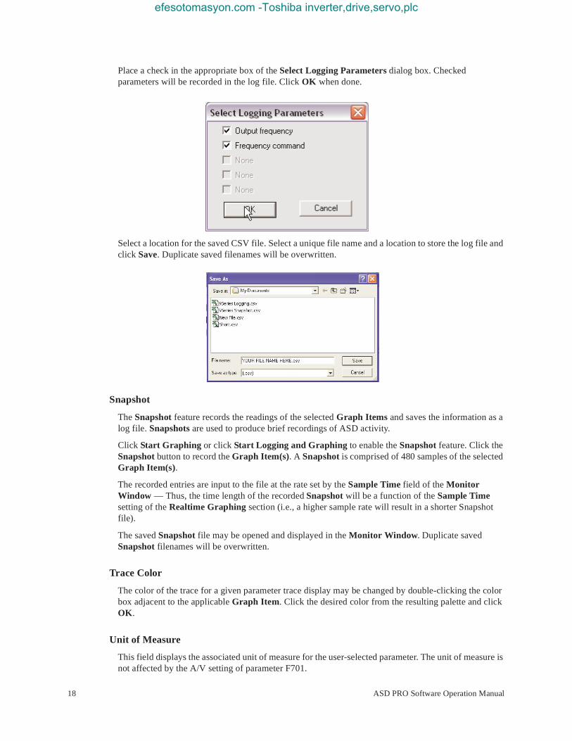
Place a check in the appropriate box of the Select Logging Parameters dialog box. Checked parameters will be recorded in the log file. Click OK when done.
Select a location for the saved CSV file. Select a unique file name and a location to store the log file and click Save. Duplicate saved filenames will be overwritten.
Snapshot
The Snapshot feature records the readings of the selected Graph Items and saves the information as a log file. Snapshots are used to produce brief recordings of ASD activity.
Click Start Graphing or click Start Logging and Graphing to enable the Snapshot feature. Click the Snapshot button to record the Graph Item(s). A Snapshot is comprised of 480 samples of the selected Graph Item(s).
The recorded entries are input to the file at the rate set by the Sample Time field of the Monitor Window — Thus, the time length of the recorded Snapshot will be a function of the Sample Time setting of the Realtime Graphing section (i.e., a higher sample rate will result in a shorter Snapshot file).
The saved Snapshot file may be opened and displayed in the Monitor Window. Duplicate saved Snapshot filenames will be overwritten.
Trace Color
The color of the trace for a given parameter trace display may be changed by double-clicking the color box adjacent to the applicable Graph Item. Click the desired color from the resulting palette and click OK.
Unit of Measure
This field displays the associated unit of measure for the user-selected parameter. The unit of measure is not affected by the A/V setting of parameter F701.
18 ASD PRO Software Operation Manual

efesotomasyon.com -Toshiba inverter,drive,servo,plc
Offset
The Offset setting is useful if the displayed parameter has a positive and a negative property. This function may be used to change the position of the measured quantity on the graph. By default, the zero reference is zero and the Offset is set to -50 when displaying bipolar values.
The Offset may be changed for a given parameter using the up/down arrows to raise or lower the display of the measured quantity. This feature is also useful when viewing two values that have the same amplitude on a given axis. The Offset of either may be changed to provide non-overlapping traces on the display.
Multiplication Factor (X)
The Multiplication Factor (X) is used to display data that would otherwise exceed the range of the graph (greater than 100 or outside of the -50 to +50 range). The Multiplication Factor is selected automatically and is not user-selectable. The Multiplication Factor scales the reading to fit the screen. A reading of 150 is displayed as 75 with a multiplication factor of 2 in the X field.
Log Data Information
The View Log Data button allows the user to select and display previously recorded log and Snapshot files (see Snapshot on pg. 18). The resulting file data is displayed in the Monitor Window graph as the Graph Items that were selected for logging or for a Snapshot when saved.
The log file name and the date that the log file was created are displayed in the Log Data Information section of the Monitor Window. The Brief and Detail radio buttons of the Log Data Information section scale the Monitor Window graph display. The Brief and Detail buttons are only used while viewing recorded log and Snapshot files.
The graph view may be set to Brief or Detail to view only a section of a saved file or to view the entire saved file, respectively. The Brief button displays the data log of 24 hours. The Detail button displays approximately 90 seconds of the data log per screen.
Note: Because the logs are created using the time clock of the PC as a time stamp, ensure that the PC clock is set to the correct time and date.
To view log data, click the View Log Data button of the Graph Items section. From the Open dialog box, path to the recorded log or Snapshot file to be viewed, and click Open. The Detail button of the Log Data View section will be used for most log views. However, to locate the start of a log that is less than a few hours long may require using the Brief view.
Trip/Alarm Record
Any trip and/or alarm events are recorded and listed in this section for the active session. To clear this information close and then restart the ASD PRO Software.
Trip Trace
Parameter F740 must be set to At Trip to use this function.
The Trip Trace function is used to set the default storage location for saved trip data. Place a check in the Trip Trace box to open the Save As dialog box. Path to the desired storage location and click Save. The selected location will be used for all subsequent trip data saves. Duplicate saved filenames will be overwritten.
The saved file will be stored as File Name.csv. CSV (Comma Separated Value) files are of the format of a text file that can be read using the Microsoft Excel® application or a similar text processing program.
To change the location when required, uncheck the Trip Trace box and then re-check the Trip Trace box.
ASD PRO Software Operation Manual 19

efesotomasyon.com -Toshiba inverter,drive,servo,plc
Monitor Items
Monitor Items
The Monitor Items list contains all of the ASD monitored parameters and is updated at 2-second intervals. The Monitor Items section is read-only and provides the status of ASD input, ASD output, and control/system variables.
The Monitor Items list may be disabled by setting the Mon Items While Graphing (see Realtime Graphing section of screen) radio button to Off. Disabling the Monitor Items list terminates Monitor Items updates and is effective in providing better throughput of ASD-to-PC read/write data for the graphing functions.
Terminal Status
The Terminal Status section shows the status of the discrete input and discrete output terminals. When configuring a discrete output terminal (from the Tree Window), NC is used as a suffix to the setting to denote Normally Closed.
The Terminal Status display is updated at 2-second intervals. The Terminal Status section is updated regardless of the Mon Items While Graphing setting.
20 ASD PRO Software Operation Manual

efesotomasyon.com -Toshiba inverter,drive,servo,plc
Tree WindowThe Tree Window (see Figure 6) is accessed via the pull-down menu Windows ⇒ Tree Window and is used to read from or to write to all of the ASD memory locations that are accessible via communications.
Clicking a parameter from the Tree Window reads the current value (or setting) for the selected parameter and displays it in the Current Value field. While the selected parameter number and parameter setting are displayed, the Current Value field may be changed to a new value. Click the Write button to load the changed value into the ASD memory.
Note: Clicking the Write button updates the Table Window and the EOI display of the connected ASD for the changed parameter.
Note: To display changes made via the EOI of the ASD at the Tree Window, click the changed parameter at the Tree Window. If the changed parameter number is displayed at the Tree Window during the EOI change, click to another parameter of the Tree Window and then back to update the changed parameter.
A known parameter number may also be keyed into the Direct Access field to view or change the setting of the parameter entered (four digits are required for the Direct Access field, i.e., 0009, 0109, etc.). Once changed, click Write to transfer the new settings to the ASD. Otherwise, the changed setting will not be written to the ASD.
To use either method to change a parameter value, the Direct Access number of the parameter must appear in the Direct Access field. The desired parameter value/setting may then be keyed in or selected from the Current Value pull-down menu. Click Write to load the new value into the ASD memory or exit the Tree Window without clicking the Write button to close the Tree Window and discard any changes.
Note: For further information on the parameters of the Tree Window, see the installation and operation manual of the connected ASD.
Figure 6. Tree Window.
Tree Window Items
Name — Selected parameter name.
Direct Access — Direct Access number of the selected parameter.
Write — Click to transfer new settings to the ASD.
Current Value — Current value/setting of the selected parameter.
ASD PRO Software Operation Manual 21

efesotomasyon.com -Toshiba inverter,drive,servo,plc
Typical — Default value.
Maximum — Maximum value to which the selected parameter may be set (if applicable).
Minimum — Minimum value to which the selected parameter may be set (if applicable).
Changeable During Run — Parameter changeability status while running.
Auto Update — This function, when enabled (box checked), allows for parameter changes made from the Table Window or from the EOI of the ASD to be conveyed to the associated Tree Window field without user intervention. The Tree Window becomes read-only and is disabled for input of parameter changes while the Auto Update feature is enabled.
The Auto Update function requires that the user click the item from the Tree Window list to display the updated parameter value/setting in the Current Value field of the Tree Window.
Changes made to a parameter via the EOI of the connected ASD will update the Table Window for that parameter without user intervention. Table Window updates in this manner require that the ASD Read/Write feature of the Table Window be enabled (radio button checked).
If the Auto Update feature is not enabled, click the Value field of a given parameter of the Table Window to display/update ASD parameter changes made via the EOI.
22 ASD PRO Software Operation Manual

efesotomasyon.com -Toshiba inverter,drive,servo,plc
Table WindowThe Table Window (see Figure 7) is accessed via the pull-down menu Windows ⇒ Table Window. The Table Window allows the user to read from or to write to all ASD memory locations that are accessible via communications.
The Table Window is a file creation/editing/transfer mechanism that may be used to create or change a transferable ASD configuration (e.g., group-transfer of one or more parameter changes or settings). All of the parameter changes or settings of the Table Window may be saved as a file, recalled, and applied to an ASD as required or transferred to multiple ASDs of the same typeform.
Click the Comm, Title, or Function field of a given parameter for Help information on the selected parameter.
Figure 7. Table Window.
Using the Table Window
The following procedure is to be performed by Qualified Personnel ONLY.
1. Save the starting ASD configuration by clicking the Read All From ASD button of the Table Window. The Value column will then be populated with the current values/settings of the connected ASD.
2. Upon completion, click the Save to File button. Select the descriptive Items To Save from the resulting dialog box — all listed parameters will be saved regardless of the dialog box selections. Selecting from the descriptive Items To Save list increases the information included in the saved file for each parameter. If no items are selected (Comm Number and Current Value selections are fixed and may not be de-selected) the resulting file will include the Communications Number and the setting for each Parameter only. Give the file to be saved a unique name. Duplicate file names will be overwritten.
ASD PRO Software Operation Manual 23
efesotomasyon.com -Toshiba inverter,drive,servo,plc
The resulting file contains the starting parameter settings of the ASD and may be re-loaded into the ASD upon completion of the ASD PRO Software diagnostics, if required.
3. Perform the ASD PRO Software diagnostic functions as required (see ASD PRO Software Menu Navigation on pg. 14 operational information). Parameter changes made to the table may be transferred to the ASD individually or as a group. Click the Write To ASD button to transfer the individual setting displayed at the Table Window Current Value field to the ASD. Or click Write All To ASD to transfer the entire table to the ASD.
4. The starting ASD parameter settings saved at Step 2 may be restored to the ASD upon completion of the diagnostics by clicking Load From File (Edit Table mode required). Path to the saved file of Step 2 and click Open.
5. Once the saved file from Step 2 is opened click Write All To ASD at the Table Window to load the original ASD configuration file into the ASD.
6. Close the ASD PRO Software application.
Note: Only after the completion of the ASD PRO Software closure should the power be removed from the ASD.
7. Remove power from the ASD.
8. Disconnect the ASD-CAB-USB cable from the ASD and the PC. Close or replace any ASD covers, doors, or guards.
Only after Qualified Personnel have confirmed that the ASD operation is as expected and as required for the application should the motor be connected and final-tested.
9. Re-apply ASD power and verify that the ASD operation is correct and as expected.
WARNING
24 ASD PRO Software Operation Manual
efesotomasyon.com -Toshiba inverter,drive,servo,plc
ASD Read/Write — Edit Table Functions
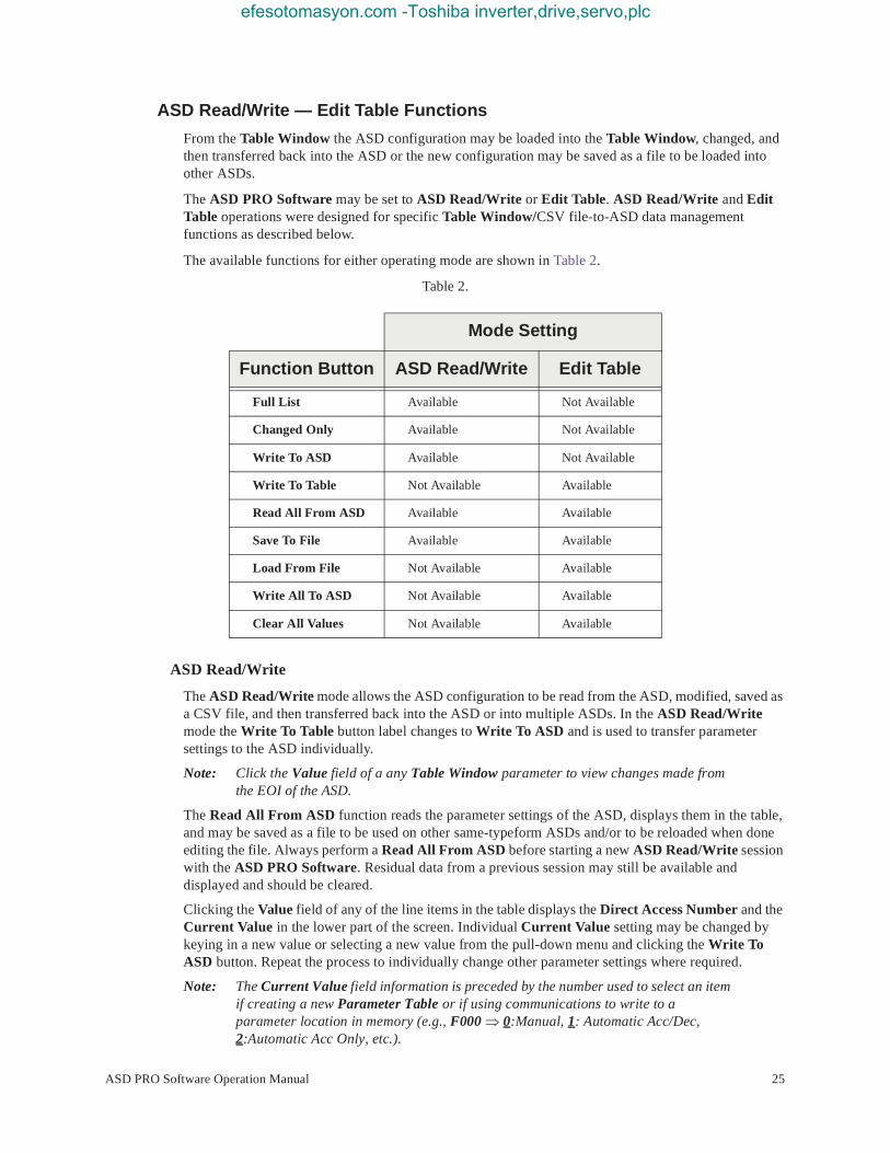
From the Table Window the ASD configuration may be loaded into the Table Window, changed, and then transferred back into the ASD or the new configuration may be saved as a file to be loaded into other ASDs.
The ASD PRO Software may be set to ASD Read/Write or Edit Table. ASD Read/Write and Edit Table operations were designed for specific Table Window/CSV file-to-ASD data management functions as described below.
The available functions for either operating mode are shown in Table 2.
Table 2.
ASD Read/Write
The ASD Read/Write mode allows the ASD configuration to be read from the ASD, modified, saved as a CSV file, and then transferred back into the ASD or into multiple ASDs. In the ASD Read/Write mode the Write To Table button label changes to Write To ASD and is used to transfer parameter settings to the ASD individually.
Note: Click the Value field of a any Table Window parameter to view changes made from the EOI of the ASD.
The Read All From ASD function reads the parameter settings of the ASD, displays them in the table, and may be saved as a file to be used on other same-typeform ASDs and/or to be reloaded when done editing the file. Always perform a Read All From ASD before starting a new ASD Read/Write session with the ASD PRO Software. Residual data from a previous session may still be available and displayed and should be cleared.
Clicking the Value field of any of the line items in the table displays the Direct Access Number and the Current Value in the lower part of the screen. Individual Current Value setting may be changed by keying in a new value or selecting a new value from the pull-down menu and clicking the Write To ASD button. Repeat the process to individually change other parameter settings where required.
Note: The Current Value field information is preceded by the number used to select an item if creating a new Parameter Table or if using communications to write to a parameter location in memory (e.g., F000 ⇒ 0:Manual, 1: Automatic Acc/Dec, 2:Automatic Acc Only, etc.).
Mode Setting
Function Button ASD Read/Write Edit Table
Full List Available Not Available
Changed Only Available Not Available
Write To ASD Available Not Available
Write To Table Not Available Available
Read All From ASD Available Available
Save To File Available Available
Load From File Not Available Available
Write All To ASD Not Available Available
Clear All Values Not Available Available
ASD PRO Software Operation Manual 25

efesotomasyon.com -Toshiba inverter,drive,servo,plc
Edit Table
The Edit Table mode is used to create a new Parameter Table or to modify an existing Parameter Table and does not require that an ASD be connected to the PC — transfers of the new settings to the ASD are optional. See the section titled Short Tables on pg. 28 for more information on creating a new table.
In the Edit Table mode the Write To ASD button label changes to Write To Table and the Clear All Values button appears. The Clear All Values button clears all of the values from the Table Window and allows for the entry of values to be used for user-selected parameter items.
To create a new Parameter Table file, click the Edit Table radio button and then click the Clear All Values button. In the Value column, click the row of the parameter to be entered into the new Parameter Table.
In the lower part of the Table Window the Default value, Minimum/Maximum value, and the Changeable During Run status appears for the selected parameter.
Input the required parameter value/setting in the Current Value field. Enter the numerical value for measured items (i.e., time, magnitude, etc.) or select a setting from the pull-down menu and then click the Write to Table button. The Selection Number may also be entered into the Value field for items of a Selection List [i.e., Command Mode Selection: 0:Terminal Block, 1:Panel Keypad, 2:RS485 (2-wire), 3:RS485 (4-wire), 4:Communication Option Board]. Click the parameter of interest in the Function column to see the listing of the Selection Numbers.
To modify an existing Parameter Table table click the Edit Table radio button, click the Load From File button, and path to the CSV file to be modified. Click Open and the values from the selected file will populate the Value column with the values of the selected CSV file.
Input the desired parameter value change(s) and click Write to Table after each change.
Click Save to File and the new CSV file is created or the modified file is saved with the changes. The new or modified file requires a unique name. Duplicate file names will be overwritten when saved.
The CSV file may also be opened using MS Excel® for further evaluation.
For a more in-depth description of the file transfer buttons of the Table Window see the section titled Parameters on pg. 27.
Compare Files
The Compare Files check box is used to compare the displayed Value column listing to a Value column listing of a saved file.
To use this feature click Read All From ASD or click Load from File to populate the Value column of the Table Window. Click the Compare Files check box and, from the resulting dialog box and path to the file that is to be compared to the Value column listing. Click Open.
The Unit column title changes to CSV File. The CSV File column lists the values/settings of the compared CSV file. Items that are different from the Value column listing are listed in red text.
26 ASD PRO Software Operation Manual

efesotomasyon.com -Toshiba inverter,drive,servo,plc
ParametersThe Parameters pull-down menu provides quick access to the read-all and the write-all data transfer functions of the Table Window to and from the ASD and the PC (via CSV file).
Read All From ASD (to Table)The Read All From ASD pull-down selection opens the Table Window and reads the parameter settings of the connected ASD and displays the results in the Table Window.
This function may be carried out in either the ASD Read/Write mode or the Edit Table mode. The Table Window information may be saved as a CSV file and loaded into another ASD or stored on the PC for future use.
The ASD PRO Software is not sensitive to versions or revisions of the different ASD software that may be loaded onto the connected ASD. The ASD PRO Software attempts to read all possible user parameters from the ASD.
Different versions of ASD firmware may have added parameters. These parameters will not read from some versions of the ASD software and will cause a Reading Error in the message box of the Table Window. A Reading Error should be investigated for assurance that the cause is not harmful. If in doubt, contact the Toshiba Customer Support Center with the firmware version and revision information of the ASD accompanied by a list of the parameters that caused the Reading Error.
Save (from Table) To FileThe Save To File function transfers the current Table Window parameter table file to the PC in the CSV format. The saved file will not contain any data until the Read All From ASD function or the Load From File function has been executed for the current session.
Selecting the Save To File function prompts the user to select additional measurement properties to be contained within the CSV file to be saved. The default selections are Communications Number and Current Value (both are fixed and cannot be deselected). The default selected properties may not provide enough information in the resulting CSV file.
Place additional check(s) in the adjacent boxes of the properties to be saved in the CSV file as required.
Click OK to save the file. Create a file name and select the storage location when prompted at the subsequent Save As
ASDTable Window
CSV File
Table Window
ASD PRO Software Operation Manual 27

efesotomasyon.com -Toshiba inverter,drive,servo,plc
dialog box. Or click the Cancel button at the Select items to save dialog box to cancel the save operation.
Note: Because no default file name is provided in the Save As file name field, using the word Params in the file name will differentiate the stored Parameter Tables from the stored Log files.
The saved file may be written to a parameter table then loaded into other ASDs and run as required.
The resulting file created from the Read All From ASD function followed by a Save To File command causes hundreds of parameters to be saved to a user specified CSV file. Some applications will not require that the entire list of parameters be saved.
The creation of a Short Table provides for this condition and is described in the next section.
Short Tables
A Long Table is comprised of the complete list of parameters read and saved via the Read All From ASD function and the Save To File function. A Short Table is a subset of a Long Table and is comprised of only those parameters specific to a given application (user-selected). Short tables may be used when only specific parameters are required to be downloaded to various ASDs of the same type.
For instance, if it is required that all of the ASDs in an installation have acceleration and deceleration times of 63 seconds, a short table can be created as a template that will change only those two parameters and no others.
Before using the newly created short table, the table should be verified to be correct and after loading into an ASD, the correct operation of the ASD should be verified. After loading the table into an ASD turn off the ASD and allow the capacitors to discharge completely. Then turn on the ASD and check the ASD for correct operation.
This assures that the parameters have been loaded into the memory of the ASD and that the new settings are correct.
Creating a Short Table File
1. From the Table Window click the radio button Edit Table radio button.
2. Click the Clear All Values button. This will clear any residual values from a previous session that may be in the Value column of the table.
3. Click the Value field of the first parameter to be used to create the short table. Enter the new parameter value in the Current Value field. Click Write To Table to enter the data into the table.
4. Repeat Step 3 for each item to be added to the Short Table File. Click Write To Table for each new value/setting entry.
5. After the last parameter value is written to the table, click Save To File. When prompted, provide a unique name and location for the saved file (i.e., yourfilename.csv). Duplicate filenames will be overwritten.
Loading a Short Table File
1. Connect the PC loaded with the ASD PRO Software application to the target ASD and establish ASD-to-PC communications (see ASD-to-PC Connections on pg. 11).
2. From the Table Window click the Edit Table radio button.
3. Click Load From File and path to the saved short table yourfilename.csv file (Step 5 at Creating a Short Table File).
28 ASD PRO Software Operation Manual

efesotomasyon.com -Toshiba inverter,drive,servo,plc
4. Click Write All To ASD to write the contents of the short table to the ASD.
Note: In the event that errors are detected during the writing process see the section titled Write All To ASD (from Table) on pg. 29.
5. Remove power from the ASD (see Charge LED go off) and then re-apply power to the ASD.
6. Verify the functionality of the ASD to ensure that the settings are correct and as expected.
Load From File (to Table)The Load From File function transfers the CSV file from the PC to the Table Window. The parameter table information may be transferred to the ASD by using the Write All To ASD function and run.
Click the Full List radio button or the Changed Only radio button to select the items that are used to populate the table listing. The Full List button allows for the display of the complete listing of all ASD parameters and the values that are loaded into the ASD. The Changed Only button allows for the display of those parameter settings of the ASD that are different from the factory default settings only.
To avoid producing unexpected results, the new parameter table should be tested thoroughly before applying to groups of ASDs or being used to run a motor.
Once a CSV file is opened and loaded into the ASD, clicking a Value column parameter of the Table Window displays the value stored in the ASD (this also updates the displayed value if the parameter was changed via the EOI). To update the entire table click the Read All From ASD button of the Table Window.
The table may be modified and, using the Save to File function, saved to the PC in the CSV format. The modified file may be loaded into the ASD and run as required.
Write All To ASD (from Table)The Write All To ASD function writes the complete Table Window listing of parameters into the connected ASD. This function may be carried out in the Edit Table mode only.
The ASD PRO Software is not sensitive to versions or revisions of the different ASD software that may be loaded onto the connected ASD. The ASD PRO Software attempts to write to a list of all possible user parameters to the ASD.
Different versions of ASD firmware may have added parameters. These added parameters will not write to some versions of ASDs and will cause a Write Error in the message box of the Table Window.
A Write Error should be investigated for assurance that the cause is not harmful. If in doubt, contact the Toshiba Customer Support Center with the firmware version and revision information of the ASD and a list of the associated parameter numbers of the Write Errors.
It is recommended that after writing a table to an ASD that the following procedure be performed:
1. Exit the ASD PRO Software and remove the PC connection to the ASD.
2. Remove power from the ASD and allow the charge capacitors to discharge completely (see Charge LED go off).
3. Restore power and reconnect the PC to the ASD.
4. From the Table Window click Read All From ASD.
Ensure that the parameter settings read from the ASD are correct and as required.
ASD PRO Software Operation Manual 29

efesotomasyon.com -Toshiba inverter,drive,servo,plc
Start Up
The Start Up pull-down menu provides quick access to the following commonly used parameters:
• Acc/Dec Settings on pg. 31,
• Pattern Run Settings on pg. 33,
• PID Settings on pg. 35,
• Preset Speed Setting on pg. 36,
• Terminal Settings on pg. 37,
• Torque Control Settings on pg. 39, and
• My Function on pg. 41.
30 ASD PRO Software Operation Manual

efesotomasyon.com -Toshiba inverter,drive,servo,plc
Acc/Dec Settings
The Accel/Decel Settings screen is comprised of two setup screens that are selectable via the top-edge Accel/Decel tabs: Accel/Decel Pattern and the Accel/Decel Switching screens.
The two screens are used to specify the time in seconds (rate) for the output of the ASD to go from 0.0 Hz to the Maximum Frequency (Acc) and from the Maximum Frequency to 0.0 Hz (Dec).
The Acc/Dec settings are also used to determine the acceleration and deceleration rates of the UP/DOWN Frequency functions.
Note: An acceleration time shorter than the load will allow may cause nuisance tripping and mechanical stress to loads. Automatic Accel/Decel, Stall, and Ridethrough settings may lengthen the acceleration and deceleration times.
Accel/Decel Pattern
The Acc/Dec Pattern may be set to the Linear, S-Pattern 1 or S-Pattern 2 profile. The default settings of either pattern may be adjusted to meet application-specific requirements.
Figure 8 shows the Acc/Dec profile of the Linear, S-Pattern 1, and S-Pattern 2 settings. See parameters F009, F010, F502, F503, F506, F507, F508, F509, F512, and F516 of the ASD installation and operation manual of the ASD being used for more information on these settings.
Available setting types are either Numerical or of a Selection List and are parameter number specific. To change the setting for either type, click the item in the Function column to enter the Edit mode.
Either key in a numerical value or select an item from the selection listing.
Click another item from the Function column to exit the Edit mode without saving the change or click the Set button to save the new setting.
Figure 8. Accel/Decel Pattern Settings.
Set Field
ASD PRO Software Operation Manual 31
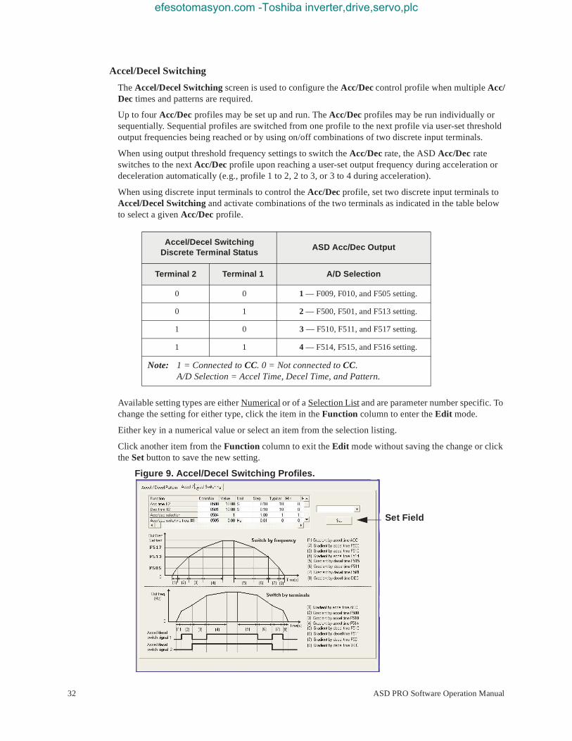
efesotomasyon.com -Toshiba inverter,drive,servo,plc
Accel/Decel Switching
The Accel/Decel Switching screen is used to configure the Acc/Dec control profile when multiple Acc/Dec times and patterns are required.
Up to four Acc/Dec profiles may be set up and run. The Acc/Dec profiles may be run individually or sequentially. Sequential profiles are switched from one profile to the next profile via user-set threshold output frequencies being reached or by using on/off combinations of two discrete input terminals.
When using output threshold frequency settings to switch the Acc/Dec rate, the ASD Acc/Dec rate switches to the next Acc/Dec profile upon reaching a user-set output frequency during acceleration or deceleration automatically (e.g., profile 1 to 2, 2 to 3, or 3 to 4 during acceleration).
When using discrete input terminals to control the Acc/Dec profile, set two discrete input terminals to Accel/Decel Switching and activate combinations of the two terminals as indicated in the table below to select a given Acc/Dec profile.
Available setting types are either Numerical or of a Selection List and are parameter number specific. To change the setting for either type, click the item in the Function column to enter the Edit mode.
Either key in a numerical value or select an item from the selection listing.
Click another item from the Function column to exit the Edit mode without saving the change or click the Set button to save the new setting.
Figure 9. Accel/Decel Switching Profiles.
Accel/Decel Switching Discrete Terminal Status
ASD Acc/Dec Output
Terminal 2 Terminal 1 A/D Selection
0 0 1 — F009, F010, and F505 setting.
0 1 2 — F500, F501, and F513 setting.
1 0 3 — F510, F511, and F517 setting.
1 1 4 — F514, F515, and F516 setting.
Note: 1 = Connected to CC. 0 = Not connected to CC. A/D Selection = Accel Time, Decel Time, and Pattern.
Set Field
32 ASD PRO Software Operation Manual
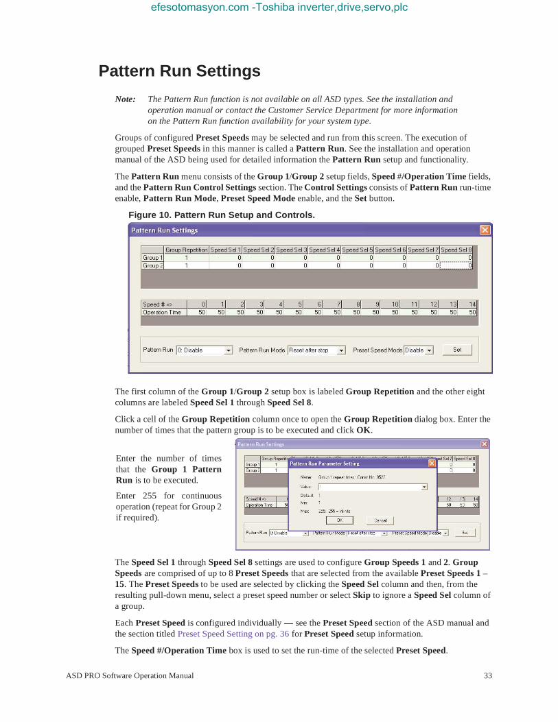
efesotomasyon.com -Toshiba inverter,drive,servo,plc
Pattern Run Settings
Note: The Pattern Run function is not available on all ASD types. See the installation and operation manual or contact the Customer Service Department for more information on the Pattern Run function availability for your system type.
Groups of configured Preset Speeds may be selected and run from this screen. The execution of grouped Preset Speeds in this manner is called a Pattern Run. See the installation and operation manual of the ASD being used for detailed information the Pattern Run setup and functionality.
The Pattern Run menu consists of the Group 1/Group 2 setup fields, Speed #/Operation Time fields, and the Pattern Run Control Settings section. The Control Settings consists of Pattern Run run-time enable, Pattern Run Mode, Preset Speed Mode enable, and the Set button.
Figure 10. Pattern Run Setup and Controls.
The first column of the Group 1/Group 2 setup box is labeled Group Repetition and the other eight columns are labeled Speed Sel 1 through Speed Sel 8.
Click a cell of the Group Repetition column once to open the Group Repetition dialog box. Enter the number of times that the pattern group is to be executed and click OK.
The Speed Sel 1 through Speed Sel 8 settings are used to configure Group Speeds 1 and 2. Group Speeds are comprised of up to 8 Preset Speeds that are selected from the available Preset Speeds 1 – 15. The Preset Speeds to be used are selected by clicking the Speed Sel column and then, from the resulting pull-down menu, select a preset speed number or select Skip to ignore a Speed Sel column of a group.
Each Preset Speed is configured individually — see the Preset Speed section of the ASD manual and the section titled Preset Speed Setting on pg. 36 for Preset Speed setup information.
The Speed #/Operation Time box is used to set the run-time of the selected Preset Speed.
Enter the number of times that the Group 1 Pattern Run is to be executed.
Enter 255 for continuous operation (repeat for Group 2 if required).
ASD PRO Software Operation Manual 33

efesotomasyon.com -Toshiba inverter,drive,servo,plc
The Pattern Run field is used to enable the Pattern Run function once the setup is complete. The Operation Time unit of measure is also set here; select minutes or seconds.
The Pattern Run Mode selection is used to set the disposition of the system at the conclusion of the Group1 and/or Group 2 Pattern Run.
The Preset Speed Mode setting is used to determine if only the speed setting of the setup is to be used for the selected Preset Speed (Disabled) or if the Direction, Acc/Dec, V/f, and the Torque Limit settings are to be used (Enabled) in the programmed Pattern Run.
34 ASD PRO Software Operation Manual

efesotomasyon.com -Toshiba inverter,drive,servo,plc
PID SettingsThe PID Settings screen allows for quick access to the PID setup parameters. Parameters F359 – F373 are used to set the ASD output deviation range, source and sensitivity settings of the control feedback, and to set limits on the degree that PID-control may affect the output of the ASD. See the installation and operation manual of the ASD being used for more information on PID settings.
Available setting types are either Numerical or of a Selection List and are parameter number specific. To change the setting for either type, click the item in the Function column to enter the Edit mode.
Either key in a numerical value or select an item from the selection listing at the lower part of the screen.
Click another item from the Function column to exit the Edit mode without saving the change or click the Set button to save the new setting.
Figure 11. PID Settings Screen.
ASD PRO Software Operation Manual 35
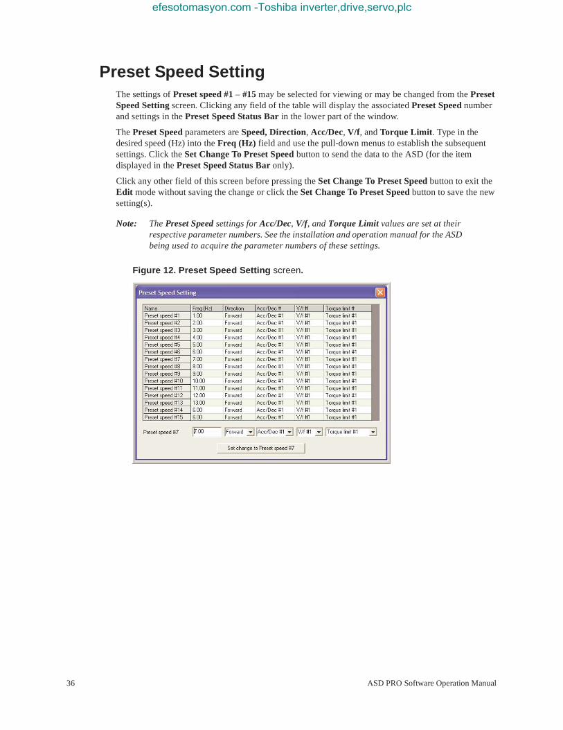
efesotomasyon.com -Toshiba inverter,drive,servo,plc
Preset Speed SettingThe settings of Preset speed #1 – #15 may be selected for viewing or may be changed from the Preset Speed Setting screen. Clicking any field of the table will display the associated Preset Speed number and settings in the Preset Speed Status Bar in the lower part of the window.
The Preset Speed parameters are Speed, Direction, Acc/Dec, V/f, and Torque Limit. Type in the desired speed (Hz) into the Freq (Hz) field and use the pull-down menus to establish the subsequent settings. Click the Set Change To Preset Speed button to send the data to the ASD (for the item displayed in the Preset Speed Status Bar only).
Click any other field of this screen before pressing the Set Change To Preset Speed button to exit the Edit mode without saving the change or click the Set Change To Preset Speed button to save the new setting(s).
Note: The Preset Speed settings for Acc/Dec, V/f, and Torque Limit values are set at their respective parameter numbers. See the installation and operation manual for the ASD being used to acquire the parameter numbers of these settings.
Figure 12. Preset Speed Setting screen.
36 ASD PRO Software Operation Manual

efesotomasyon.com -Toshiba inverter,drive,servo,plc
Terminal SettingsThe Terminal Settings window shown in Figure 13 on pg. 38 is used to assign functions to the discrete input and output terminals and to scale the analog input terminals.
Select the desired input or output terminal to be configured from one of the three tabs: Input Terminals, Output Terminals, or Analog Input Terminal.
To assign a function to an Input or Output terminal click the function field of the desired terminal and the current assignment is displayed in the field adjacent to the Set button. Click the pull-down arrow of this field and scroll up or down to select a new setting. Discrete terminal settings must also be set to Normally Open or Normally Closed (NC).
Exit the Terminal Settings window without clicking the Set button to close the Terminal Settings window and discard any changes or click the Set button to write the new terminal setting to the ASD.
Delay response times for the discrete input terminals are entered in milli-seconds and are set from the Response Time section of the Terminal Settings window. Click the Set Time button to transfer the milli-second delay time changes to the ASD.
Note: Clicking the Set button transfers the settings for the item in the edit field ONLY. Clicking the Set button will not apply the untransferred changes made to any of the other tab screens (i.e., setting the F terminal to Preset Speed 1 and clicking the Set button from the Output Terminals screen will not apply the Preset Speed 1 function to the F terminal).
The Analog Input Terminal screen is used to scale the VI/II, RR, or RX inputs. The required values may be entered into the Input Reference Point #1 and #2 fields or the values may be set using the line of the graphical display. Left-click and hold the line to drag it to the desired location. Exit the Analog Input Terminal window without clicking the Set Points button to close the window and discard any changes or click the Set Points button to write the new settings to the ASD.
See the installation and operation manual for the ASD being used for more information on configuring analog input terminals.
ASD PRO Software Operation Manual 37
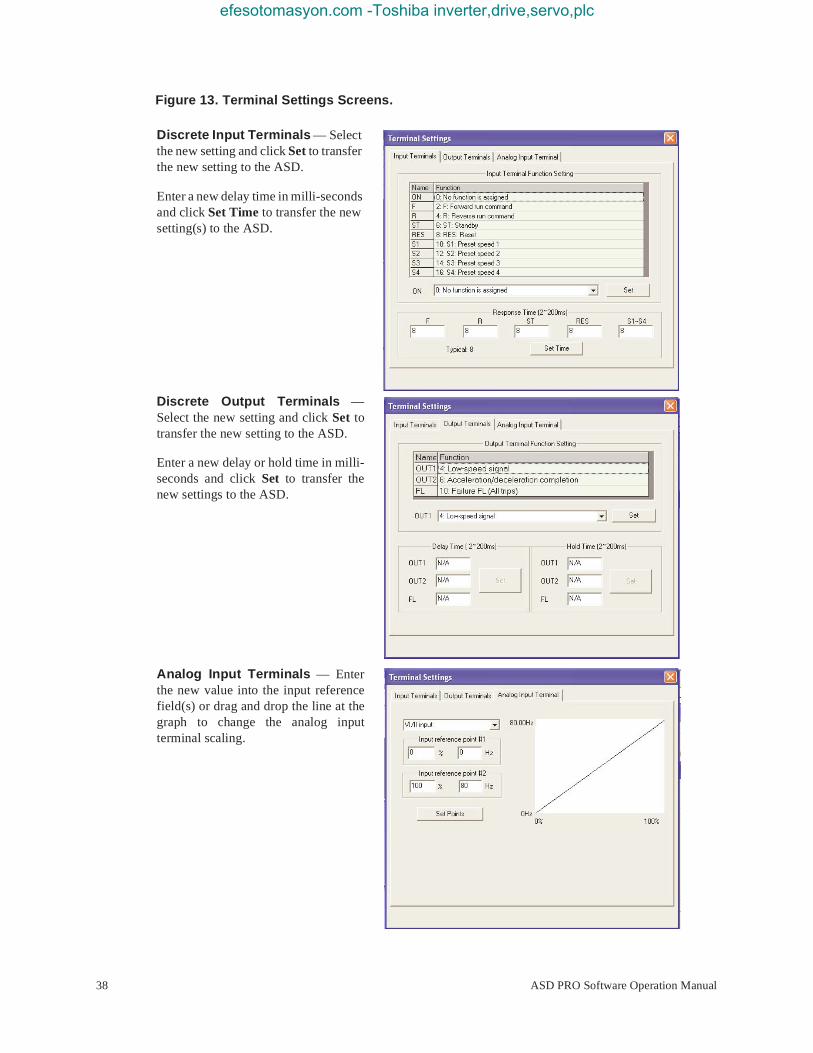
efesotomasyon.com -Toshiba inverter,drive,servo,plc
Figure 13. Terminal Settings Screens.
Discrete Input Terminals — Select the new setting and click Set to transfer the new setting to the ASD.
Enter a new delay time in milli-seconds and click Set Time to transfer the new setting(s) to the ASD.
Discrete Output Terminals — Select the new setting and click Set to transfer the new setting to the ASD.
Enter a new delay or hold time in milli-seconds and click Set to transfer the new settings to the ASD.
Analog Input Terminals — Enter the new value into the input reference field(s) or drag and drop the line at the graph to change the analog input terminal scaling.
38 ASD PRO Software Operation Manual

efesotomasyon.com -Toshiba inverter,drive,servo,plc
Torque Control SettingsThe Torque Control Settings screen allows for quick access to the Torque Reference, Speed Limit, Torque Bias, and the Torque Limit control settings via top-edge tabs.
Note: The Torque Control Settings described here are not available on all ASD types. See the installation and operation manual for the ASD being used or contact the Customer Service Department for more information on torque-control settings.
Torque Reference — Selects a torque reference input (VI/II, RR, or RX) and is used to perform the associated scaling of the selected input. The required values may be entered into the Set Torque Reference fields or the values may be set using the Point 1 and Point 2 Ref/Torque line of the graphical display.
To set using the graphical display left-click the line and drag to the desired location. Click Set All when done to transfer the final settings to the ASD.
Speed Limit — Sets a Reverse and Forward speed limit that may not be exceeded in an attempt to control the output torque.
This limit level is set using the analog inputs (VI/II, RR, or RX) or it may be fixed using the parameter F426 setting.
See parameters F425, F426, F427, and F428 of the ASD installation and operation manual for more information on this setting.
Torque Bias — Sets the Torque Bias input. Torque Bias aids in applications in which the load should not be allowed to force motor rotation while waiting for the output torque of the ASD to reach a sufficient level to maintain the load (e.g., hoists and elevators).
In a lifting application Torque Bias is used to add lifting torque to a load that is suspended when the brake is released or when the direction changes to provide a smooth lift. For heavier loads this value should be set higher for smoother operation.
ASD PRO Software Operation Manual 39

efesotomasyon.com -Toshiba inverter,drive,servo,plc
Torque Limit — Sets the Power Running Torque Limit and the Regenerative Torque Limit for profile #1 and may be controlled by an analog input or fixed in accordance with the settings of F441 and F443, respectively. Set F441 and F443 and/or select an analog input from this screen.
Torque Limit settings for profiles 2 – 4 are fixed in accordance with settings of this screen.
40 ASD PRO Software Operation Manual

efesotomasyon.com -Toshiba inverter,drive,servo,plc
My FunctionThe My Function feature is used to enhance the programmability of the G9 ASD by performing two programmable functions: 1) the Combined Terminal Function, and 2) Logic Operations (i.e., PLC functions).
Up to seven My Function operating profiles (Units) may be programmed and executed. Select the Unit (1–7) and complete the programming to use each Unit. With each Unit selection the associated parameter numbers are displayed.
Parameters F900 to F977 are used to setup the My Function feature.
The My Function dialog box is shown below along with a brief description of the fields of the dialog box. See the My Function Instruction Manual and the ASD installation and operation manual of the ASD being used for more information on the setup and operation of My Function.
The flow lines of the My Function dialog box may require that the user adjust the PC settings to allow the lines to be displayed properly (Right-click at Desktop ⇒ Properties ⇒Appearance ⇒ Color Scheme).
Function StatusAn activated terminal or an asserted function reports Onor 1.
Parameter NumbersWith each Unit selection the associated parameter numbers are displayed.
ASD PRO Software Operation Manual 41

efesotomasyon.com -Toshiba inverter,drive,servo,plc
My Function Selections and Features
Because the ALWAYS ON sett ing or an activated MY FUNCTION WITH PERMISSION SIGNAL discrete input te rminal sett ing enables the system and the motor to run upon the successful complet ion of the My Function setup, these sett ings are to be completed last when performing the My Function setup.
Disable — Click to turn off the My Function feature. While disabled the My Function dialog box will display the outcome of the programmed operations, but will not apply the outcome to the ASD or to the motor.
My Function With Permission Signal — Once the My Function feature is setup via parameters F900 to F977, click this radio button to enable My Function to be carried out as programmed via a discrete input terminal (set the terminal to My Function Run Signal).
Always On — Click this radio button for a continuous My Function enable. Always On enables the system and motor to run upon the successful completion of the My Function setup.
Next Unit — Used to select the Unit to be run using My Function. Once setup and enabled, all units are active and will produce the results of their programming. Ensure that all unused parameters of the unused units are set to NOP and Deselect. This will disable the unused unit(s) and ensure that the motor will not be activated unexpectedly via unused units.
Unit 1 – Unit 7 Function and Settings
Unit 1 is used for the following My Function dialog box descriptions. Units 2 – 7 are labeled and function identically using different parameter numbers.
The settings of the My Function parameters may be selected for viewing or may be changed from the My Function dialog box. Clicking any field of the My Function dialog box will display the associated settings in the My Function Status Bar in the lower part of the dialog box.
Select the My Function setting from the My Function Status Bar pull-down menu and press Write To ASD (for each change) to transfer the new setting to the ASD.
Input Function Target 1 — Is used as an input terminal assignment (holder) that is set to a terminal label or to a system status and is used in the My Function equation. The value assigned to Input Function Target 1 may be a user-set terminal assignment or it may be set to a systemic operating variable (e.g., output current, discrete terminal status, input voltage, etc.). In either case, the value of this terminal is used as a conditional input to be used to make the determination of the output of the My Function equation.
Input Function Target 2 — Is used as an input terminal assignment (holder) that is set to a terminal label or to a system status and is used in the My Function equation. The value assigned to Input Function Target 2 may be a user-set terminal assignment or it may be set to a systemic operating variable (e.g., output current, discrete terminal status, input voltage, etc.). In either case, the value of this terminal is used as a conditional input to be used to make the determination of the output of the My Function equation.
WARNING
42 ASD PRO Software Operation Manual

efesotomasyon.com -Toshiba inverter,drive,servo,plc
Input Function Target 3 — Is used as an input terminal assignment (holder) that is set to a terminal label or to a system status and is used in the My Function equation. The value assigned to Input Function Target 3 may be a user-set terminal assignment or it may be set to a systemic operating variable (e.g., output current, discrete terminal status, input voltage, etc.). In either case, the value of this terminal is compared with the outcome of the combined Input Function Target 1 and Input Function Target 2. The outcome of the compare function is used to make the determination of the output of the My Function equation.
Input Function Command 2 — Is used to assign a user-selected logical operator to two user-selected Input Function Target variables, enable a counter/timer function, or to perform a hold/reset function.
Output Function Assigned — Assigns the function of the Output Function Assigned data location to one of the functions listed in the Input Setting field of the Discrete Output Terminal Assignments listing. The listing for a given ASD type may be found in the ASD installation and operation manual of the ASD being used.
ASD PRO Software Operation Manual 43

efesotomasyon.com -Toshiba inverter,drive,servo,plc
EOI
EOI FPWizardThe EOI FPWizard is accessed via the pull-down menu EOI ⇒ FPWizard. The FPWizard provides access to a 7- and 9-Series ASD EOI for updating the EOI Flash from a PC.
The ASD PRO Software and the ASD-EOI-HH-G9 docking station (see Figure 14 on pg. 45) are required to flash the display module. The ASD-EOI-HH-G9 docking station may be acquired from your Toshiba Sales Representative.
Display Module Update Procedure
1. Remove power from the ASD.
2. Remove the display module to be flashed from the ASD (see the installation and operation manual of the ASD for more information on removing the module). Insert the display module into the docking station.
3. Connect the 9-pin D-type male-to-female connector from the docking station to the PC.
4. Apply +24 – +30 VDC to the docking station.
5. Start the ASD PRO Software application.
6. Once PC-to-Docking Station connectivity is established, close all sub-windows within the ASD PRO Software application (Table Window, Control Window, etc.).
7. From the EOI pull-down menu of the ASD PRO Software, select EOI FPWizard. Click Next at the subsequent Welcome screen.
8. Click the Yes or No radio button at the Choose EOI Version dialog box and then click Next.
9. At the Select Port and File dialog box, browse to the hex file to be loaded into the display module and click Next.
10. Click Start at the Loading Hex File to EOI dialog box and the hex file download will begin.
11. Upon completion of the hex file download remove the power from the docking station.
12. Remove the display module from the docking station.
13. Install the updated display module into the EOI assembly of the ASD for which it is to be used.
44 ASD PRO Software Operation Manual

efesotomasyon.com -Toshiba inverter,drive,servo,plc
Figure 14. 9-Series EOI Flash Docking Station.
EOI ReadingThis is a read-only feature that reads and displays the revision and version of the EOI flash for the 9-Series family of ASDs. This function is not available for the 7-Series ASDs.
RS232 Serial Communication30VDC
9-pin D-typemale-to-female cable
ASD PRO Software Operation Manual 45

efesotomasyon.com -Toshiba inverter,drive,servo,plc
Help
About ASD PRO SoftwareASD PRO version and release information.
7SProvides parameter descriptions and usage assistance for the 7-series ASD.
9SProvides parameter descriptions and usage assistance for the 9-series ASD.
ManualsThe Installation and Operation Manuals of the hardware systems for which the ASD PRO Software may be used can be found at the TIC web site: www.tic.toshiba.com\ind.
Additional information on the systems and services provided by Toshiba may also be found at the TIC web site.
46 ASD PRO Software Operation Manual

Index
efesotomasyon.com -Toshiba inverter,drive,servo,plc
Numerics7S, 469S, 46
AAcc/Dec Setting, 31ASD PRO Software Operation, 13ASD Read/Write, 25ASD-to-PC Connections, 11
CChanged Only radio button, 29Clear All Values, 26Compare Files, 26Concerns about this publication, 3Connect, 14Control Window, 15Create a new Parameter Table, 26Creating a Short Table File, 28Customer Support, 4
DDirect Access field, 21Disconnect, 14
EEdit Table, 26Emergency Off, 6Equipment Inspection, 3Exit, 14
FFull List radio button, 29
GGeneral Safety Information, 1Getting Started, 7Graph Items, 17
Hhelp information, 23
LLoad From File (to Table), 29Load the ASD PRO Software, 7Load the TIC_USB_RS485 Driver Software, 10Loading a Short Table File, 28Log Data Information, 19
MManual’s Purpose and Scope, 3Manuals, 46Menu Items, 14Menu Navigation, 14Modify an existing Parameter Table, 26Monitor Item, 20Monitor Window, 16Multiplication Factor, 19
OOffset, 19
PParameters, 27Pattern Run Settings, 33Preset Speed Settings, 36
QQualified Personnel, 3
RRead All From ASD (to Table), 27Realtime Graphing, 16
SSave (from Table) To File, 27Save Window Config., 14
47 ASD PRO Software Operation Manual

efesotomasyon.com -Toshiba inverter,drive,servo,plc
Serial Comm, 7Short Table File, 28Snapshot, 18Software Licensing Agreement, 1Special Symbols, 2Start Up, 30Start/Stop Graphing, 17Start/Stop Logging and Graphing, 17Stop Graphing, 17Stop Logging and Graphing, 17System Protection, 6
TTable Window, 23Terminal Settings, 37Terminal Status, 20
Trace Color, 18Tree Window, 21Tree Window Items, 21Trip Trace, 19Trip/Alarm Record, 19
UUnit of Measure, 18
WWindows, 15Write All To ASD (from Table), 29Write To ASD, 24Write To Table, 25
48 ASD PRO Software Operation Manual

efesotomasyon.com -Toshiba inverter,drive,servo,plc

TOSHIBATOSHIBA INTERNATIONAL CORPORATION
INDUSTRIAL DIVISION13131 West Little York Road, Houston, TX 77041TEL: (713) 466-0277 — FAX: (713) 937-9349
Printed in the U.S.A.
efesotomasyon.com -Toshiba inverter,drive,servo,plc