Embed Size (px)
Citation preview
MANUAL FOR ENGINEERED WOOD CONSTRUCTION
American Wood Council
AmericanForest &
PaperAssociation
2001 EDITIONSUPPLEMENTSpecial DesignProvisions forWind and Seismic
06-02 20M
American Forest & Paper AssociationAmerican Wood Council1111 19th Street, NWSuite 800Washington, DC [email protected]
America's Forest & Paper People ®
Improving Tomorrow's Environment Today ®
®
®
ASD/LRFDALLOWABLE STRESS
DESIGN
LOAD AND RESISTANCE
FACTOR DESIGN
Seismic 2001 Cover.pmd 6/9/02, 7:48 PM1
2001 EDITIONSUPPLEMENTSpecial DesignProvisions forWind and Seismic
MANUAL FOR ENGINEEREDWOOD CONSTRUCTION
ASD/LRFDALLOWABLE STRESS
DESIGN
Copyright © 2001
American Forest & Paper Association, Inc.
LOAD AND RESISTANCEFACTOR DESIGN
Seismic FM draft.pmd 5/3/02, 10:35 AM1
Table of ContentsChapter/Title Page
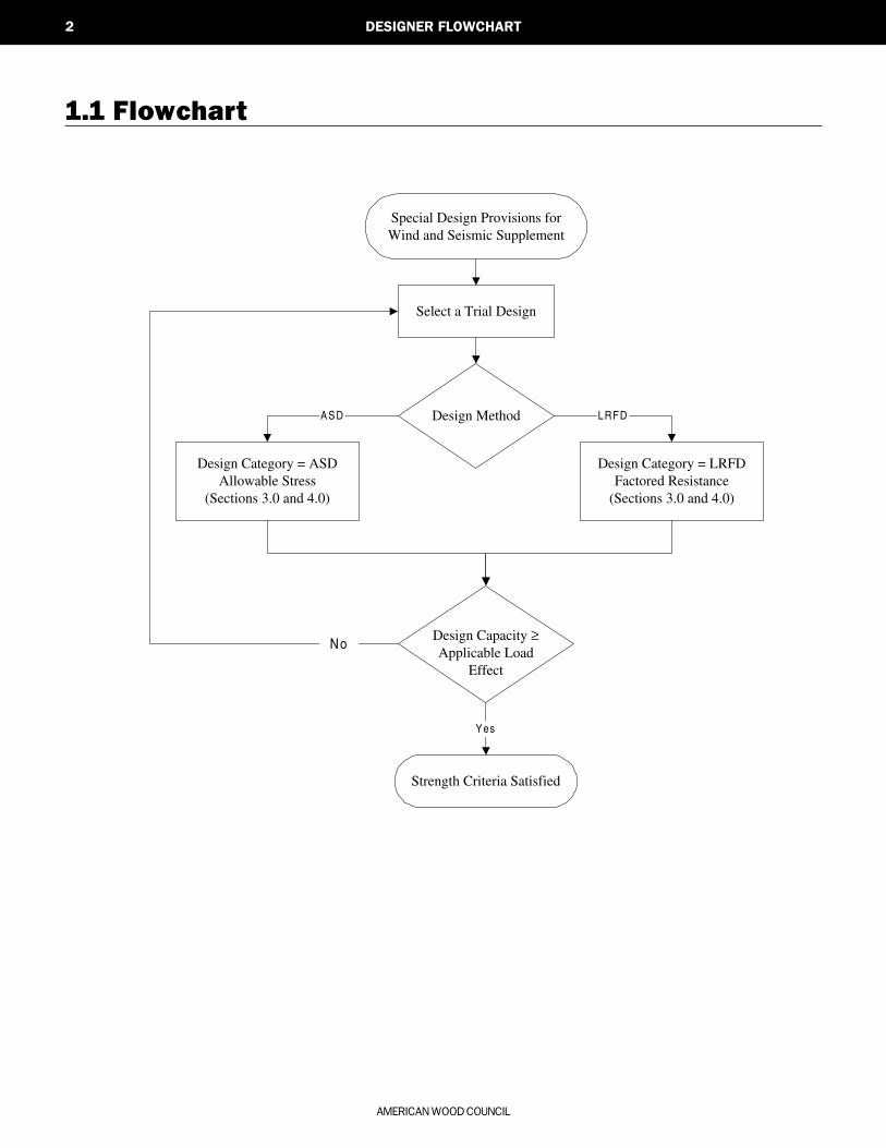
1 Designer Flowchart ..................................................11.1 Flowchart
2 General Design Requirements .. 32.1 General2.2 Terminology2.3 Notation
3 Members and Connections .................73.1 Framing3.2 Sheathing3.3 Connections
List of Tables
AMERICAN FOREST & PAPER ASSOCIATION
3.1.1.1 Wall Stud Bending Stress Increase Factors .......... 8
3.2A Nominal Uniform Load Capacities, psf,for Wall Sheathing Resisting Wind Loads ............. 9
3.2B Nominal Uniform Load Capacities, psf,for Roof Sheathing Resisting Wind Loads ........ 10
4.2.4 Maximum Diaphragm Aspect Ratios(Horizontal or Sloped Diaphragms) .......................... 13
4.2A Nominal Unit Shear Values for Wood-FrameDiaphragms (Blocked Wood Structural PanelDiaphragms) ............................................................................................ 16
4.2B Nominal Unit Shear Values for Wood-FrameDiaphragms (Unblocked Wood StructuralPanel Diaphragms) .......................................................................... 17
4.2C Nominal Unit Shear Values for Wood-FrameDiaphragms (Lumber Diaphragms) ........................... 18
4.3.3.4 Shear Capacity Adjustment Factor, Co ................... 20
4.3.4 Maximum Shear Wall Aspect Ratios ........................ 21
4.3A Nominal Unit Shear Values for Wood-FrameShear Walls (Wood-based Sheathing) ..................... 25
4.3B Nominal Unit Shear Values for Wood-FrameShear Walls (Gypsum and Cement Plaster) ..... 26
4.3C Nominal Unit Shear Values for Wood-FrameShear Walls (Lumber Shear Walls) ............................. 27
ASD/LRFD SUPPLEMENT – SPECIAL DESIGN PROVISIONS FOR WIND AND SEISMIC
Chapter/Title Page
4 Lateral Force-ResistingSystems .............................................................................................. 11
4.1 General4.2 Wood Diaphragms4.3 Wood Shear Walls
5 References .................................................................................29
Seismic FM draft.pmd 5/3/02, 10:35 AM2

AMERICAN FOREST & PAPER ASSOCIATION
1
DESIGNERFLOWCHART
1.1 Flowchart 2
1
ASD/LRFD SUPPLEMENT – SPECIAL DESIGN PROVISIONS FOR WIND AND SEISMIC
Seismic C1 Draft.pmd 1/28/02, 4:58 PM1
AMERICAN WOOD COUNCIL
2 DESIGNER FLOWCHART
Special Design Provisions forWind and Seismic Supplement
Design Category = ASDAllowable Stress
(Sections 3.0 and 4.0)
Design Capacity ≥Applicable Load
Effect
Select a Trial Design
Design Method
Design Category = LRFDFactored Resistance
(Sections 3.0 and 4.0)
LRFDASD
Strength Criteria Satisfied
Yes
No
1.1 Flowchart
Seismic C1 Draft.pmd 1/28/02, 4:58 PM2
AMERICAN FOREST & PAPER ASSOCIATION
3
GENERALDESIGNREQUIREMENTS
2.1 General 4
2.2 Terminology 4
2.3 Notation 5
ASD/LRFD SUPPLEMENT – SPECIAL DESIGN PROVISIONS FOR WIND AND SEISMIC
2
Seismic C2 Draft.pmd 5/30/02, 3:18 PM3
AMERICAN WOOD COUNCIL
4 GENERAL DESIGN REQUIREMENTS
2.1 General
2.1.1 Scope
The provisions of this Supplement cover materials,design and construction of wood members, fasteners, andassemblies to resist wind and seismic forces.
2.1.2 Design Methods
Engineered design of wood structures to resist windor seismic forces shall be by one of the methods describedin Section 2.1.2.1 and 2.1.2.2.
Exception: Wood structures shall be permittedto be constructed in accordance with prescriptive
provisions permitted by the authority having ju-risdiction.
2.1.2.1 Allowable Stress Design: Allowable stress de-sign (ASD) shall be in accordance with the NationalDesign Specification® (NDS®)for Wood Construction(ANSI/AF&PA NDS-2001), its supplements, and provi-sions of this Supplement.
2.1.2.2 Strength Design: Load and resistance factordesign (LRFD) of wood structures shall be in accordancewith the Load and Resistance Factor Standard for Engi-neered Wood Construction (AF&PA/ASCE 16-95), itssupplements, and provisions of this Supplement.
2.2 Terminology
ALLOWABLE STRESS DESIGN A method of pro-portioning structural members such that elasticallycomputed stresses produced in the members by nominalloads does not exceed specific allowable stresses (alsocalled working stress design).
BOUNDARY ELEMENT Diaphragm and shear wallboundary members to which sheathing transfers forces.Boundary elements include chords and collectors at dia-phragm and shear wall perimeters, interior openings,discontinuities and re-entrant corners.
CHORD A boundary element perpendicular to the ap-plied load that is assumed to resist axial stresses due tothe induced moment.
COLLECTOR A diaphragm or shear wall element par-allel and in line with the applied force that collects andtransfers diaphragm shear forces to the vertical elementsof the lateral force-resisting system and/or distributesforces withing the diaphragm.
DIAPHRAGM A roof, floor or other membrane bracingsystem acting to transmit lateral forces to the vertical re-sisting elements. When the term “diaphragm” is used, itincludes horizontal bracing systems.
DIAPHRAGM, BLOCKED A diaphragm in which alladjacent sheathing edges are fastened to either commonframing or common blocking.
DIAPHRAGM, FLEXIBLE A diaphragm is flexible forthe purpose of distribution of story shear when the com-puted maximum in-plane deflection of the diaphragm itself
under lateral load is greater than two times the averagedeflection of adjoining vertical elements of the lateralforce-resisting system of the associated story under equiva-lent tributary lateral load.
DIAPHRAGM, RIGID A diaphragm is rigid for the pur-pose of distribution of story shear and torsional momentwhen the computed maximum in-plane deflection of thediaphragm itself under lateral load is less than or equal totwo times the average deflection of adjoining vertical el-ements of the lateral force-resisting system of theassociated story under equivalent tributary lateral load.For analysis purposes, it can be assumed that a rigid dia-phragm distributes story shear and torsional moment intolines of shear walls by the relative lateral stiffness of theshear walls.
[For the first iteration, an arbitrary load is ap-plied to each line of shear walls to determine therelative stiffness of the lines of walls. Once therelative stiffnesses of the wall lines have been de-termined, the applied lateral load is distributedproportionally. The shear walls are redesignedand the lateral stiffness is recalculated and theapplied load is re-apportioned. This is continueduntil convergence.]
DIAPHRAGM, UNBLOCKED A diaphragm that hasedge nailing at supporting members only. Blocking be-tween supporting structural members at panel edges is not
Seismic C2 Draft.pmd 5/30/02, 3:18 PM4

AMERICAN FOREST & PAPER ASSOCIATION
GENER
AL D
ES
IGN R
EQ
UIR
EM
ENTS
5ASD/LRFD SUPPLEMENT – SPECIAL DESIGN PROVISIONS FOR WIND AND SEISMIC
2
included. Diaphragm panels are field nailed to support-ing members.
DIAPHRAGM BOUNDARY A location where shear istransferred into or out of the diaphragm sheathing. Trans-fer is either to a boundary element or to anotherforce-resisting element.
FIBERBOARD A fibrous, homogeneous panel madefrom lignocellulosic fibers (usually wood or cane) andhaving a density of less than 31 pounds per cubic foot(497 kg/m3) but more than 10 pounds per cubic foot (160kg/m3).
HARDBOARD A fibrous-felted, homogeneous panelmade from lignocellulosic fibers consolidated under heatand pressure in a hot press to a density not less than 31pounds per cubic foot.
LATERAL STIFFNESS The inverse of the deforma-tion of shear walls under an applied unit load, or the forcerequired to deform a shear wall a unit distance.
NOMINAL STRENGTH Strength of a member, crosssection, or connection before application of any strengthreduction factors.
ORIENTED STRAND BOARD A mat-formed woodstructural panel product composed of thin rectangularwood strands or wafers arranged in oriented layers andbonded with waterproof adhesive.
PARTICLEBOARD A generic term for a panel prima-rily composed of cellulosic materials (usually wood),generally in the form of discrete pieces or particles, asdistinguished from fibers. The cellulosic material is com-bined with synthetic resin or other suitable bonding systemby a process in which the interparticle bond is created bythe bonding system under heat and pressure.
PERFORATED SHEAR WALL A sheathed wall withopenings, but which has not been specifically designedand detailed for force transfer around wall openings.
PERFORATED SHEAR WALL SEGMENT A sec-tion of a perforated shear wall with full height sheathingwhich meets the requirements for maximum aspect ratioin Section 4.3.4.
PLYWOOD A wood structural panel comprised of pliesof wood veneer arranged in cross-aligned layers. Theplies are bonded with an adhesive that cures on applica-tion of heat and pressure.
REQUIRED STRENGTH Strength of a member, crosssection, or connection required to resist factored loads orrelated internal moments and forces.
RESISTANCE FACTOR A factor that accounts forunavoidable deviations of the actual strength from thenominal value and the manner and consequences of fail-ure.
SEISMIC DESIGN CATEGORY A classification as-signed to a structure based on its Seismic Use Group andthe severity of the design earthquake ground motion atthe site.
SHEAR WALL A wall designed to resist lateral forcesparallel to the plane of a wall.
SHEAR WALL LINE A series of shear walls in a line ata given story level.
SUBDIAPHRAGM A portion of a larger wood dia-phragm designed to anchor and transfer local forces toprimary diaphragm struts and the main diaphragm.
TIE-DOWN (HOLD-DOWN) A device used to resistuplift of the chords of shear walls.
WOOD STRUCTURAL PANEL A panel manufacturedfrom veneers; or wood strands or wafers; or a combina-tion of veneer and wood strands or wafers; bondedtogether with waterproof synthetic resins or other suit-able bonding systems. Examples of wood structuralpanels are plywood, oriented strand board (OSB), or com-posite panels.
2.3 Notation
A = Area of chord cross-section, in.2
A = Area of end post cross-section, in.2
C = Compression chord force, lbs.
Co
= Shear capacity adjustment factor from Table
4.3.3.4.
E = Modulus of elasticity of end posts, psi
E = Modulus of elasticity of diaphragm chords, psi
G = Specific gravity
Ga
= Apparent shear wall shear stiffness from nail
slip and panel shear deformation, kips/in. (from
Column A, Table 4.3).
Seismic C2 Draft.pmd 5/30/02, 3:18 PM5
AMERICAN WOOD COUNCIL
6 GENERAL DESIGN REQUIREMENTS
2. The maximum clear height from top of
diaphragm to bottom of diaphragm framing
above.
t = Uniform uplift force, lbs./ft.
ν = Induced unit shear, lbs./ft.
νs
= Nominal unit shear capacity for seismic design,
lbs./ft.
νmax
= Maximum induced unit shear force, lbs./ft.
νsc
= Combined nominal unit shear capacity of two-
sided shear wall for seismic design, lbs./ft.
νs1
= Nominal unit shear capacity for side 1, lbs./ft.
(from Column A, Table 4.3).
νs2
= Nominal unit shear capacity for side 2, lbs./ft.
(from Column A, Table 4.3).
νw
= Nominal unit shear capacity for wind design,
lbs./ft
νwc
= Combined nominal unit shear capacity of two-
sided shear wall for wind design, lbs./ft.
x = Distance from chord splice to nearest support,
in.
∆c
= Diaphragm chord splice slip at the induced unit
shear in diaphragm, in.
∆a
= Total vertical elongation of wall anchorage
system (including fastener slip, device
elongation, rod elongation, etc) at the induced
unit shear in the shear wall, in.
δdia
= Maximum diaphragm deflection determined by
elastic analysis, in.
δsw
= Maximum shear wall deflection determined by
elastic analysis, in.
φb
= Sheathing resistance factor for out of plane
bending
φD
= Sheathing resistance factor for in-plane shear
of shearwalls and diaphragms
Ω0
= System overstrength factor
Ga
= Apparent diaphragm shear stiffness from nail
slip and panel shear deformation, kips/in. (from
Column A, Table 4.2).
Gac
= Combined apparent shear wall shear stiffness
of two-sided shear wall, kips/in.
Ga1
= Apparent shear wall shear stiffness for side 1,
kips/in. (from Column A, Table 4.3).
Ga2
= Apparent shear wall shear stiffness for side 2,
kips/in. (from Column A, Table 4.3).
Kmin
= Minimum ratio of v1/G
a1 or v
2/G
a2
L = The dimension of a diaphragm perpendicular to
the direction of application of force. For open-
front structures, L is the length from the edge of
the diaphragm at the open front to the vertical
resisting elements parallel to the direction of
the applied force.
Lc
= The length of the cantilever for a cantilever
diaphragm, ft. (see figure 4.2.5.2)
ΣLi
= Sum of perforated shear wall segment lengths,
ft.
R = Response modification coefficient
T = Tension chord force, lbs.
V = Induced shear force in perforated shear wall,
lbs.
W = Diaphragm width, ft.
W = The width of a diaphragm in the direction of
application of force measured as the sheathed
dimension of the diaphragm.
b = The length of a shear wall or shearwall segment
measured as the sheathed dimension of the
shear wall.
bs
= Shear wall length for determining apect ratio.
For perforated shearwalls, use the minimum
shearwall segment length included in the Li , ft.
h = The height of a shear wall or shearwall segment
measured as:
1. The maximum clear height from top of
foundation to bottom of diaphragm framing
above or
Seismic C2 Draft.pmd 5/30/02, 3:18 PM6
AMERICAN FOREST & PAPER ASSOCIATION
7
MEMBERS ANDCONNECTIONS
3.1 Framing 8
3.2 Sheathing 8
3.3 Connections 10
Table 3.1.1.1 Wall Stud Bending Stress Increase Factors ..... 8
Table 3.2A Nominal Uniform Load Capacities, psf, forWall Sheathing Resisting Wind Loads .............. 9
Table 3.2B Nominal Uniform Load Capacities, psf, forRoof Sheathing Resisting Wind Loads ........... 10
ASD/LRFD SUPPLEMENT – SPECIAL DESIGN PROVISIONS FOR WIND AND SEISMIC
3
Seismic C3 Draft.pmd 5/1/02, 7:46 PM7
AMERICAN WOOD COUNCIL
8 MEMBERS AND CONNECTIONS
3.1 Framing
3.1.1 Wall Framing
In addition to gravity loads, wall framing shall bedesigned to resist induced wind and seismic forces. Theframing shall be designed using methods referenced in2.1.2.1 for allowable stress design (ASD) and 2.1.2.2 forstrength design (LRFD).
3.1.1.1 Wall Stud Bending Stress Increase: The bend-ing stress for sawn lumber wood studs resisting out ofplane wind loads shall be permitted to be increased by thefactors in Table 3.1.1.1, in lieu of the 1.15 repetitive mem-ber factor, to take into consideration the load sharing andcomposite action provided by wood structural panelsheathing. The factor applies when studs are designed forbending, spaced no more than 16 inches on center, cov-ered on the inside with a minimum of ½-inch gypsumwallboard, and sheathed on the exterior with a minimumof 3/8-inch wood structural panel sheathing that is attachedto the studs using a minimum of 8d common nails spaced amaximum of 6 inches o.c. at panel edges and 12 inches o.c.at intermediate framing members.
Table 3.1.1.1 Wall Stud BendingStress Increase Factors
Stud Size System Factor2x4 1.52x6 1.42x8 1.32x10 1.22x12 1.15
3.1.2 Floor Framing
In addition to gravity loads, floor framing shall bedesigned to resist induced wind and seismic forces. Theframing shall be designed using methods referenced in2.1.2.1 for allowable stress design (ASD) and 2.1.2.2 forstrength design (LRFD).
3.1.3 Roof Framing
In addition to gravity loads, roof framing shall be de-signed to resist induced wind and seismic forces. Theframing shall be designed using methods referenced in2.1.2.1 for allowable stress design (ASD) and 2.1.2.2 forstrength design (LRFD).
3.2 Sheathing
blies to resist lateral forces shall be designed in accor-dance with 4.3.
3.2.2 Floor Sheathing
Floor sheathing shall be capable of resisting and trans-ferring gravity loads to the floor framing. Sheathing usedin diaphragm assemblies to resist lateral forces shall bedesigned in accordance with 4.2.
3.2.1 Wall Sheathing
Exterior wall sheathing and its fasteners shall be ca-pable of resisting and transferring out of plane wind loadsto the wall framing. Maximum spans and nominal uni-form load capacities for wall sheathing materials are givenin Table 3.2A. The ASD allowable uniform load capaci-ties to be used for wind design shall be determined bydividing the nominal uniform load capacities by a safetyfactor of 1.6. The LRFD factored uniform load capacitiesto be used for wind design shall be determined by multi-plying the nominal uniform load capacities by a resistancefactor, φb, of 0.85. Sheathing used in shear wall assem-
Seismic C3 Draft.pmd 5/1/02, 7:46 PM8

AMERICAN FOREST & PAPER ASSOCIATION
MEM
BER
S A
ND
CO
NNEC
TIO
NS
9ASD/LRFD SUPPLEMENT – SPECIAL DESIGN PROVISIONS FOR WIND AND SEISMIC
3
Table 3.2A Nominal Uniform Load Capacities, psf, for Wall Sheathing ResistingWind Loads1
1. Nominal capacities shall be adjusted in accordance with Section 3.2.1 to determine ASD uniform load capacity and LRFD uniform resistances.2. Sheathing shall be OSB or plywood with 4 or more plies.3. Wood structural panels shall conform to the requirements for its type in DOC PS 1 or PS2. Particleboard sheathing shall conform to ANSI A208.1.
Hardboard panel and siding shall conform to the requirements of AHA A135.5 or AHA A135.4 as applicable. Cellulosic fiberboard sheathing shallconform to AHA A194.1 or ASTM C208.
4. Tabulated values are for maximum bending loads from wind. Loads are limited by bending or shear stress assuming a 2-span continuous condition.For more information, see the ASD Wood Structural Panels Supplement.
December 15, 2001
Sheathing Type3 Span Rating or Grade MinimumThickness
(in.)Sheathing Long Dimension Orientation:
Perpendicular to Supports Parallel to Supports
Maximum Stud Spacing
(in.)
Actual StudSpacing (in.)
Maximum Stud Spacing
(in.)
Actual StudSpacing (in.)
12 16 24 12 16 24
Nominal UniformLoads (psf)
Nominal UniformLoads (psf)
Wood Structural Panels4
(Sheathing Grades, C-C, C-D, C-C Plugged, OSB)
24/024/1632/1640/2048/24
3/87/1615/3219/3223/32
2424242424
425 540 625950
1160
240 305 355 595805
105135155265360
2424242424
90110155255380
50 6090145215
– 252
402
652
902
Particleboard Sheathing(M-S Exterior Glue)
3/81/2
1616
(contactmanufacturer)
1616
(contactmanufacturer)
Particleboard PanelSiding(M-S Exterior Glue)
5/83/4
1624
(contactmanufacturer)
1624
(contactmanufacturer)
Hardboard Siding(Direct to Studs)
Lap SidingShiplap Edge Panel SidingSquare Edge Panel Siding
7/167/167/16
162424
460460460
260260260
-115115
-2424
-460460
-260260
-115115
Cellulosic FiberboardSheathing
RegularStructuralStructural
1/21/2
25/32
---
---
---
---
161616
90135 165
50 7590
---
Seismic C3 Draft.pmd 5/1/02, 7:46 PM9
AMERICAN WOOD COUNCIL
10 MEMBERS AND CONNECTIONS
3.3 Connections
3.3.1 Connections
Connections resisting induced wind and seismic forcesshall be designed in accordance with methods referencedin 2.1.2.1 for allowable stress design (ASD) and 2.1.2.2for strength design (LRFD).
3.2.3 Roof Sheathing
Roof sheathing and its fasteners shall be capable ofresisting and transferring out of plane wind and gravityloads to the roof framing. Maximum spans and nominaluniform load capacities for roof sheathing materials aregiven in Table 3.2B. The ASD allowable uniform loadcapacities to be used for out of plane wind design shall be
determined by dividing the nominal uniform load capaci-ties by a safety factor of 1.6. The LRFD factored uniformload capacities to be used for wind design shall be deter-mined by multiplying the nominal uniform load capacitiesby a resistance factor, φb, of 0.85. Sheathing used in dia-phragm assemblies to resist lateral forces shall be designedin accordance with 4.2.
December 15, 2001
Sheathing Type Span Rating or Grade MinimumThickness
(in.)
Sheathing Long Dimension Applied Perpendicular to Supports
Rafter/Truss Spacing (in.)
12 16 19.2 24
Nominal Uniform Loads (psf)
Wood Structural Panels2,3
(Sheathing Grades, C-C, C-D, C-C Plugged, OSB)
24/024/1632/1640/2048/24
3/87/1615/3219/3223/32
425 540 625950
1160
240 305 355 595805
165210245415560
105135155265360
Wood Structural Panels2,3
(Single Floor Grades,Underlayment, C-CPlugged)
16 o.c.20 o.c.24 o.c.32 o.c.48 o.c.
19/3219/3223/327/8
1-3/32
705815
108513901790
395 455 610830
1295
275 320 425 5751060
175205270370680
Table 3.2B Nominal Uniform Load Capacities, psf, for Roof Sheathing ResistingWind Loads1
1. Nominal capacities shall be adjusted in accordance with Section 3.2.3 to determine ASD uniform load capacity andLRFD uniform resistances.
2. Wood structural panels shall conform to the requirements for its type in DOC PS 1 or PS2.3. Tabulated values are for maximum bending loads from wind. Loads are limited by bending or shear stress assuming a 2-
span continuous condition. For more information, see the ASD Wood Structural Panels Supplement.
Seismic C3 Draft.pmd 5/1/02, 7:46 PM10
AMERICAN FOREST & PAPER ASSOCIATION
11
LATERALFORCE-RESISTINGSYSTEMS
4.1 General 12
4.2 Wood Diaphragms 13
4.3 Wood Shear Walls 19
Table 4.2.4 Maximum Diaphragm Aspect Ratios(Horizontal or Sloped Diaphragms) ............ 13
Table 4.2A-C Nominal Unit Shear Values for Wood-Frame Diaphragms:
A = Blocked Diaphragms ........................... 16B = Unblocked Diaphragms ...................... 17C = Lumber Diaphragms .......................... 18
Table 4.3.3.4 Shear Capacity Adjustment Factor, Co ....... 20
Table 4.3.4 Maximum Shear Wall Aspect Ratios ........... 21
Table 4.3A-C Nominal Unit Shear Values for Wood-Frame Shear Walls:
A = Wood-based Sheathing........................ 25B = Gypsum and Cement Plaster ............. 26C = Lumber Shear Walls ........................... 27
ASD/LRFD SUPPLEMENT – SPECIAL DESIGN PROVISIONS FOR WIND AND SEISMIC
4
Seismic C4 Draft.pmd 6/11/02, 6:35 PM11
AMERICAN WOOD COUNCIL
12 LATERAL FORCE-RESISTING SYSTEMS
4.1 General
4.1.5 Wood Systems ResistingHorizontal Seismic ForcesContributed by Masonry andConcrete
Wood shear walls, diaphragms, trusses and other woodassemblies shall not be used to resist horizontal seismicforces contributed by masonry or concrete construction instructures over one story in height.
Exceptions:1. Wood floor and roof assemblies shall be per-
mitted to be used in diaphragms and horizontaltrusses to resist horizontal seismic forces (in-cluding those due to masonry veneer, fireplaces,and chimneys) provided such forces do not re-sult in torsional force distribution through thetruss or diaphragm.
2. Vertical wood structural panel sheathed shearwalls shall be permitted to be used to provideresistance to seismic forces in two-story struc-tures of masonry or concrete construction,provided the following requirements are met:a. Story-to-story wall heights shall not ex-
ceed 12 feet.b. Diaphragms shall not be considered to
transmit lateral forces by torsional force dis-tribution or cantilever past the outermostsupporting shear wall.
c. Combined deflections of diaphragms andshear walls shall not permit story drift ofsupported masonry or concrete walls to ex-ceed 0.7% of the story height.
d. Wood structural panel sheathing in dia-phragms shall have all unsupported edgesblocked. Wood structural panel sheathingfor both stories of shear walls shall haveall unsupported edges blocked and, for thelower story, shall have a minimum thick-ness of 15/32 inch.
e. There shall be no out-of-plane horizontaloffsets between the first and second sto-ries of wood structural panel shear walls.
4.1.1 Design Requirements
The proportioning, design, and detailing of engineeredwood systems, members, and connections in lateral force-resisting systems shall be in accordance with methodsreferenced in 2.1.2 and provisions in this Chapter.
A continuous load path, or paths, with adequatestrength and stiffness shall be provided to transfer all forcesfrom the point of application to the final point of resis-tance.
4.1.2 Shear Capacity
Nominal shear capacities of diaphragms and shearwalls are provided for reference assemblies in Tables 4.2and 4.3, respectively. Alternatively, shear capacity of dia-phragms and shear walls shall be permitted to be calculatedby principles of mechanics using values of fastenerstrength and sheathing shear capacity.
4.1.3 Deformation Requirements
Deformation of connections within and between struc-tural elements shall be considered in design such that thedeformation of each element and connection comprisingthe lateral force-resisting system is compatible with thedeformations of the other lateral force-resisting elementsand connections and with the overall system.
4.1.4 Boundary Elements
Shear wall and diaphragm boundary elements shallbe provided to transfer the design tension and compres-sion forces. Diaphragm and shear wall sheathing shall notbe used to splice boundary elements. Diaphragm chordsand collectors shall be placed in, or in contact with, theplane of the diaphragm framing unless it can be demon-strated that the moments, shears, and deflections,considering eccentricities resulting from other configura-tions, can be tolerated without exceeding the framingcapacity and drift limits.
4.1.6 Toenails
In seismic categories D, E, and F, toenails shall not beused to transfer lateral forces greater than 150 pounds perlineal foot from diaphragms to shearwalls, drag struts toother elements, or from shear walls to other elements.
Seismic C4 Draft.pmd 6/11/02, 6:35 PM12
AMERICAN FOREST & PAPER ASSOCIATION
LATER
AL FO
RC
E-R
ES
ISTIN
G S
YS
TEM
S
4
13ASD/LRFD SUPPLEMENT – SPECIAL DESIGN PROVISIONS FOR WIND AND SEISMIC
4.2 Wood Diaphragms
Alternatively, for wood structural panel diaphragms,deflection is permitted to be calculated using a rationalanalysis where apparent shear stiffness accounts for panelshear deformation and non-linear nail slip in the sheath-ing to framing connection.
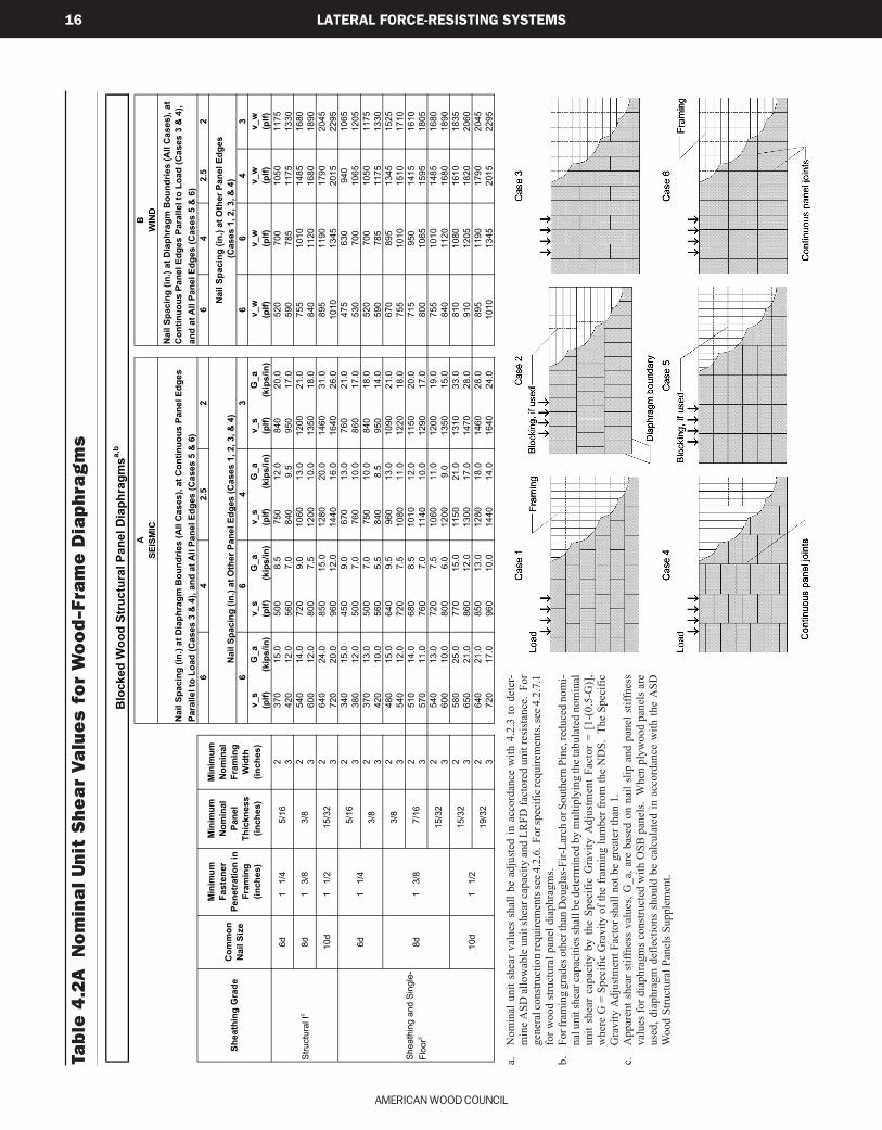
4.2.3 Shear Capacities
The nominal unit shear capacities for seismic designare provided in Column A of Tables 4.2A, B, and C andfor wind design in Column B of Tables 4.2A, B, and C.The ASD allowable unit shear capacity shall be deter-mined by dividing the nominal unit shear capacity by asafety factor of 2.0. No further increases shall be permit-ted. The LRFD factored unit resistance shall bedetermined by multiplying the nominal unit shear capac-ity by a resistance factor, φD, of 0.65.
4.2.4 Diaphragm Aspect Ratios
Size and shape of diaphragms shall be limited to theaspect ratios in Table 4.2.4.
Table 4.2.4 Maximum DiaphragmAspect Ratios(Horizontal or Sloped Diaphragms)
Diaphragm MaximumSheathing Type L/W RatioWood structural panel, unblocked 3:1Wood structural panel, blocked 4:1Single-layer straight lumber sheathing 2:1Single-layer diagonal lumber sheathing 3:1Double-layer diagonal lumber sheathing 4:1
4.2.5 Horizontal Distribution ofShear
Diaphragms shall be defined as rigid or flexible forthe purposes of distributing shear loads and designing fortorsional moments. When a diaphragm is defined as flex-ible, the diaphragm shear forces shall be distributed to thevertical resisting elements based on tributary area. Whena diaphragm is defined as rigid, the diaphragm shear forcesshall be distributed based on the relative lateral stiffnessesof the vertical resisting elements for the story below.
4.2.5.1 Torsional Irregularity: Structures with rigidwood diaphragms shall be considered as torsionally ir-
4.2.1 Application Requirements
Wood diaphragms are permitted to be used to resisthorizontal forces provided the deflection in the plane ofthe diaphragm, as determined by calculations, tests, oranalogies drawn therefrom, does not exceed the permis-sible deflection of attached load distributing or resistingelements. Connections and blocking shall extend into thediaphragm a sufficient distance to develop the force trans-ferred into the diaphragm.
4.2.2 Deflection
Permissible deflection shall be that deflection up towhich the diaphragm and any attached load distributingor resisting element will maintain its structural integrityunder design load conditions, such that the resisting ele-ment will continue to support design loads without dangerto occupants of the structure.
Calculations of diaphragm deflection shall accountfor bending and shear deflections, fastener deformation,chord splice slip, and other contributing sources of de-flection.
The midspan diaphragm deflection, δdia , is permittedto be calculated by use of the following equation:
( )35 0.25
8 1000 2c
diaa
xL L
EAW G W
∆ν νδ = + + ∑(4.2-1)
where:
E = Modulus of elasticity of diaphragm chords, psi
A = Area of chord cross-section, in.2
Ga
= Apparent diaphragm shear stiffness from nail
slip and panel shear deformation, kips/in. (from
Column A, Table 4.2)
L = Diaphragm length, ft.
ν = Induced unit shear in diaphragm, lbs./ft.
W = Diaphragm width, ft.
x = Distance from chord splice to nearest support,
in.
∆c
= Diaphragm chord splice slip at the induced unit
shear in diaphragm, in.
δdia
= Maximum diaphragm deflection determined by
elastic analysis, in.
Seismic C4 Draft.pmd 6/11/02, 6:35 PM13
AMERICAN WOOD COUNCIL
14 LATERAL FORCE-RESISTING SYSTEMS
regular when the maximum story drift, computed includ-ing accidental torsion, at one end of the structure is morethan 1.2 times the average of the story drifts at the twoends of the structure. Where torsional irregularity exists,diaphragms shall meet the following requirements:
1. The diaphragm conforms to 4.2.7.1 - 4.2.7.3.2. The L/W ratio of the diaphragm is less than
1:1 for one-story structures or 1:1½ for struc-tures over one story in height.
Exception: Where calculations show that diap-hragm deflections can be tolerated, the length, L,shall be permitted to be increased to an L/W rationot greater than 1½:1 when sheathed in conform-ance with 4.2.7.1 or to 1:1 when sheathed inconformance with 4.2.7.2 or 4.2.7.3.
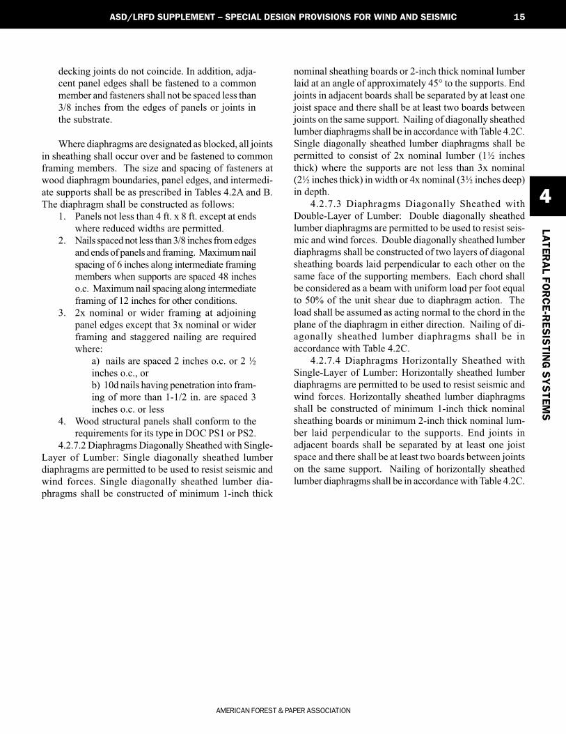
4.2.5.1.1 Open Front Structures: Open front struc-tures utilizing rigid wood diaphragms to distribute shearforces through torsion shall be permitted provided:
1. The diaphragm length, L, (normal to the openside) does not exceed 25 feet.
2. The L/W ratio (as shown in Figure 4.2.5.1)of the diaphragm is less than 1:1 for one-storystructures or 1:1½ for structures over one storyin height.
Exception: Where calculations show that diap-hragm deflections can be tolerated, the length, L,(normal to the open side) shall be permitted to beincreased to an L/W ratio not greater than 1½:1when sheathed in conformance with 4.2.7.1 or4.2.7.3 or to 1:1 when sheathed in conformancewith 4.2.7.2.
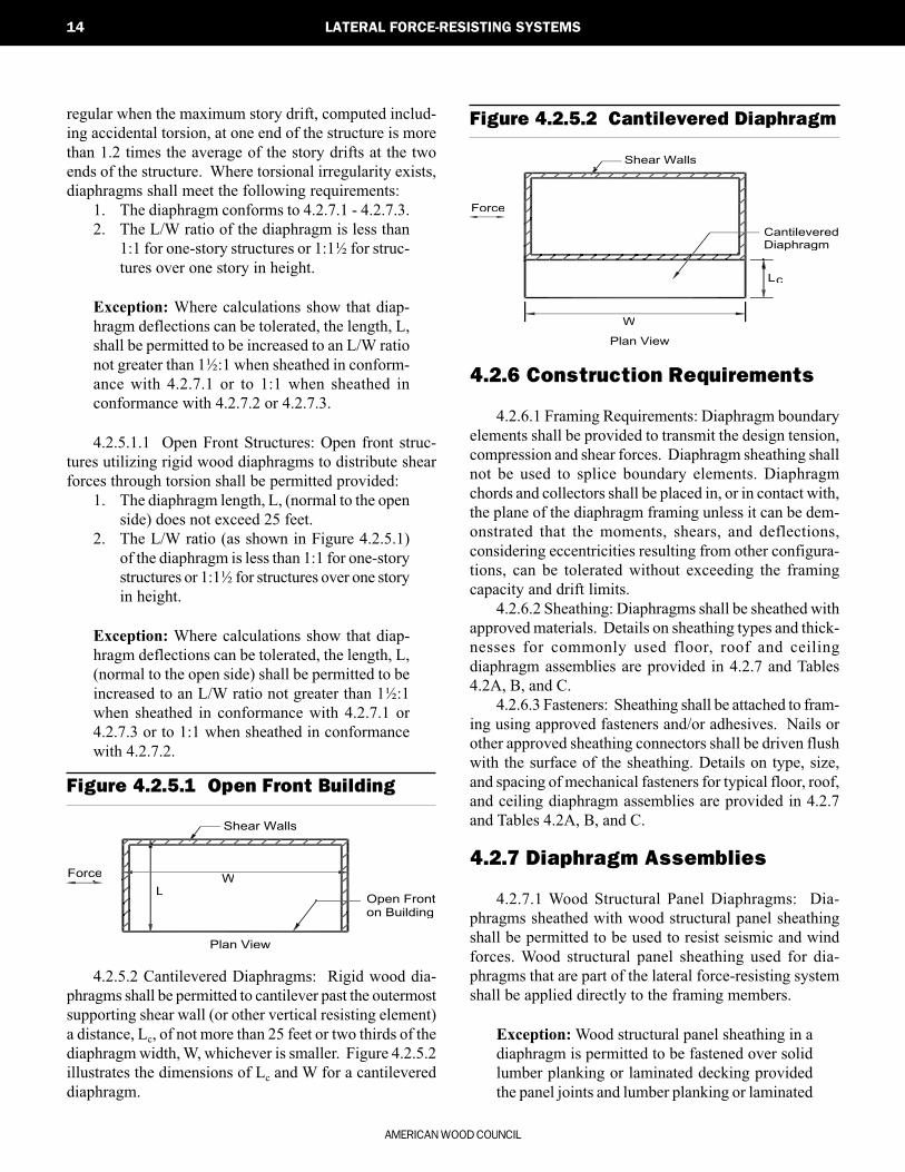
Figure 4.2.5.1 Open Front Building
Figure 4.2.5.2 Cantilevered Diaphragm
Shear Walls
WL
Force
Open Fronton Building
Plan View
Shear Walls
Force
CantileveredDiaphragm
L
W
c
Plan View
4.2.5.2 Cantilevered Diaphragms: Rigid wood dia-phragms shall be permitted to cantilever past the outermostsupporting shear wall (or other vertical resisting element)a distance, Lc, of not more than 25 feet or two thirds of thediaphragm width, W, whichever is smaller. Figure 4.2.5.2illustrates the dimensions of Lc and W for a cantilevereddiaphragm.
4.2.6 Construction Requirements
4.2.6.1 Framing Requirements: Diaphragm boundaryelements shall be provided to transmit the design tension,compression and shear forces. Diaphragm sheathing shallnot be used to splice boundary elements. Diaphragmchords and collectors shall be placed in, or in contact with,the plane of the diaphragm framing unless it can be dem-onstrated that the moments, shears, and deflections,considering eccentricities resulting from other configura-tions, can be tolerated without exceeding the framingcapacity and drift limits.
4.2.6.2 Sheathing: Diaphragms shall be sheathed withapproved materials. Details on sheathing types and thick-nesses for commonly used floor, roof and ceilingdiaphragm assemblies are provided in 4.2.7 and Tables4.2A, B, and C.
4.2.6.3 Fasteners: Sheathing shall be attached to fram-ing using approved fasteners and/or adhesives. Nails orother approved sheathing connectors shall be driven flushwith the surface of the sheathing. Details on type, size,and spacing of mechanical fasteners for typical floor, roof,and ceiling diaphragm assemblies are provided in 4.2.7and Tables 4.2A, B, and C.
4.2.7 Diaphragm Assemblies
4.2.7.1 Wood Structural Panel Diaphragms: Dia-phragms sheathed with wood structural panel sheathingshall be permitted to be used to resist seismic and windforces. Wood structural panel sheathing used for dia-phragms that are part of the lateral force-resisting systemshall be applied directly to the framing members.
Exception: Wood structural panel sheathing in adiaphragm is permitted to be fastened over solidlumber planking or laminated decking providedthe panel joints and lumber planking or laminated
Seismic C4 Draft.pmd 6/28/02, 5:12 AM14
AMERICAN FOREST & PAPER ASSOCIATION
LATER
AL FO
RC
E-R
ES
ISTIN
G S
YS
TEM
S
4
15ASD/LRFD SUPPLEMENT – SPECIAL DESIGN PROVISIONS FOR WIND AND SEISMIC
decking joints do not coincide. In addition, adja-cent panel edges shall be fastened to a commonmember and fasteners shall not be spaced less than3/8 inches from the edges of panels or joints inthe substrate.
Where diaphragms are designated as blocked, all jointsin sheathing shall occur over and be fastened to commonframing members. The size and spacing of fasteners atwood diaphragm boundaries, panel edges, and intermedi-ate supports shall be as prescribed in Tables 4.2A and B.The diaphragm shall be constructed as follows:
1. Panels not less than 4 ft. x 8 ft. except at endswhere reduced widths are permitted.
2. Nails spaced not less than 3/8 inches from edgesand ends of panels and framing. Maximum nailspacing of 6 inches along intermediate framingmembers when supports are spaced 48 incheso.c. Maximum nail spacing along intermediateframing of 12 inches for other conditions.
3. 2x nominal or wider framing at adjoiningpanel edges except that 3x nominal or widerframing and staggered nailing are requiredwhere:
a) nails are spaced 2 inches o.c. or 2 ½inches o.c., orb) 10d nails having penetration into fram-ing of more than 1-1/2 in. are spaced 3inches o.c. or less
4. Wood structural panels shall conform to therequirements for its type in DOC PS1 or PS2.
4.2.7.2 Diaphragms Diagonally Sheathed with Single-Layer of Lumber: Single diagonally sheathed lumberdiaphragms are permitted to be used to resist seismic andwind forces. Single diagonally sheathed lumber dia-phragms shall be constructed of minimum 1-inch thick
nominal sheathing boards or 2-inch thick nominal lumberlaid at an angle of approximately 45° to the supports. Endjoints in adjacent boards shall be separated by at least onejoist space and there shall be at least two boards betweenjoints on the same support. Nailing of diagonally sheathedlumber diaphragms shall be in accordance with Table 4.2C.Single diagonally sheathed lumber diaphragms shall bepermitted to consist of 2x nominal lumber (1½ inchesthick) where the supports are not less than 3x nominal(2½ inches thick) in width or 4x nominal (3½ inches deep)in depth.
4.2.7.3 Diaphragms Diagonally Sheathed withDouble-Layer of Lumber: Double diagonally sheathedlumber diaphragms are permitted to be used to resist seis-mic and wind forces. Double diagonally sheathed lumberdiaphragms shall be constructed of two layers of diagonalsheathing boards laid perpendicular to each other on thesame face of the supporting members. Each chord shallbe considered as a beam with uniform load per foot equalto 50% of the unit shear due to diaphragm action. Theload shall be assumed as acting normal to the chord in theplane of the diaphragm in either direction. Nailing of di-agonally sheathed lumber diaphragms shall be inaccordance with Table 4.2C.
4.2.7.4 Diaphragms Horizontally Sheathed withSingle-Layer of Lumber: Horizontally sheathed lumberdiaphragms are permitted to be used to resist seismic andwind forces. Horizontally sheathed lumber diaphragmsshall be constructed of minimum 1-inch thick nominalsheathing boards or minimum 2-inch thick nominal lum-ber laid perpendicular to the supports. End joints inadjacent boards shall be separated by at least one joistspace and there shall be at least two boards between jointson the same support. Nailing of horizontally sheathedlumber diaphragms shall be in accordance with Table 4.2C.
Seismic C4 Draft.pmd 6/11/02, 6:35 PM15
AMERICAN WOOD COUNCIL
16 LATERAL FORCE-RESISTING SYSTEMS
Tab
le 4
.2A
N
om
ina
l U
nit
Sh
ea
r V
alu
es
fo
r W
oo
d-F
ram
e D
iap
hra
gm
s
a.N
omin
al u
nit s
hear
val
ues
shal
l be
adju
sted
in a
ccor
danc
e w
ith 4
.2.3
to d
eter
-m
ine
ASD
allo
wab
le u
nit s
hear
cap
acity
and
LR
FD fa
ctor
ed u
nit r
esis
tanc
e. F
orge
nera
l con
stru
ctio
n re
quire
men
ts se
e 4.2
.6. F
or sp
ecifi
c req
uire
men
ts, s
ee 4
.2.7
.1fo
r woo
d st
ruct
ural
pan
el d
iaph
ragm
s.b.
For f
ram
ing
grad
es o
ther
than
Dou
glas
-Fir-
Larc
h or
Sou
ther
n Pi
ne, r
educ
ed n
omi-
nal u
nit s
hear
capa
citie
s sha
ll be
det
erm
ined
by
mul
tiply
ing
the t
abul
ated
nom
inal
unit
shea
r ca
paci
ty b
y th
e Sp
ecifi
c G
ravi
ty A
djus
tmen
t Fa
ctor
= [
1-(0
.5-G
)],
whe
re G
= S
peci
fic G
ravi
ty o
f the
fram
ing
lum
ber f
rom
the
ND
S. T
he S
peci
ficG
ravi
ty A
djus
tmen
t Fac
tor s
hall
not b
e gr
eate
r tha
n 1.
c.A
ppar
ent s
hear
stif
fnes
s va
lues
, G_a
, are
bas
ed o
n na
il sl
ip a
nd p
anel
stif
fnes
sva
lues
for d
iaph
ragm
s con
stru
cted
with
OSB
pan
els.
Whe
n pl
ywoo
d pa
nels
are
used
, dia
phra
gm d
efle
ctio
ns s
houl
d be
cal
cula
ted
in a
ccor
danc
e w
ith th
e A
SDW
ood
Stru
ctur
al P
anel
s Su
pple
men
t.
64
2.5
2
66
43
v_
sG
_a
v_
sG
_a
v_
sG
_a
v_
sG
_a
v_w
v_
wv
_w
v_
w
(plf
)(k
ips
/in
)(p
lf)
(kip
s/i
n)
(plf
)(k
ips
/in
)(p
lf)
(kip
s/i
n)
(plf
)(p
lf)
(plf
)(p
lf)
23
70
15
.05
00
8.5
75
01
2.0
84
02
0.0
52
07
00
10
50
11
75
34
20
12
.05
60
7.0
84
09
.59
50
17
.05
90
78
51
17
51
33
0
25
40
14
.07
20
9.0
10
60
13
.01
20
02
1.0
75
51
01
01
48
51
68
0
36
00
12
.08
00
7.5
12
00
10
.01
35
01
8.0
84
01
12
01
68
01
89
0
26
40
24
.08
50
15
.01
28
02
0.0
14
60
31
.08
95
11
90
17
90
20
45
37
20
20
.09
60
12
.01
44
01
6.0
16
40
26
.01
01
01
34
52
01
52
29
5
23
40
15
.04
50
9.0
67
01
3.0
76
02
1.0
47
56
30
94
01
06
5
33
80
12
.05
00
7.0
76
01
0.0
86
01
7.0
53
07
00
10
65
12
05
23
70
13
.05
00
7.0
75
01
0.0
84
01
8.0
52
07
00
10
50
11
75
34
20
10
.05
60
5.5
84
08
.59
50
14
.05
90
78
51
17
51
33
0
24
80
15
.06
40
9.5
96
01
3.0
10
90
21
.06
70
89
51
34
51
52
5
35
40
12
.07
20
7.5
10
80
11
.01
22
01
8.0
75
51
01
01
51
01
71
0
25
10
14
.06
80
8.5
10
10
12
.01
15
02
0.0
71
59
50
14
15
16
10
35
70
11
.07
60
7.0
11
40
10
.01
29
01
7.0
80
01
06
51
59
51
80
5
25
40
13
.07
20
7.5
10
60
11
.01
20
01
9.0
75
51
01
01
48
51
68
0
36
00
10
.08
00
6.0
12
00
9.0
13
50
15
.08
40
11
20
16
80
18
90
25
80
25
.07
70
15
.01
15
02
1.0
13
10
33
.08
10
10
80
16
10
18
35
36
50
21
.08
60
12
.01
30
01
7.0
14
70
28
.09
10
12
05
18
20
20
60
26
40
21
.08
50
13
.01
28
01
8.0
14
60
28
.08
95
11
90
17
90
20
45
37
20
17
.09
60
10
.01
44
01
4.0
16
40
24
.01
01
01
34
52
01
52
29
5
1
1/4
1
3/8
1
1/2
Min
imu
m
Fa
ste
ne
r
Pe
ne
tra
tio
n i
n
Fra
min
g
(in
ch
es
)
1
1/4
1
3/8
1
1/2
A
SE
ISM
IC
15
/32
7/1
6
15
/32
Sh
ea
thin
g a
nd
Sin
gle
-
Flo
orc
10
d
19
/32
8d
3/8
8d
3/8
Na
il S
pa
cin
g (
in.)
at
Oth
er
Pa
ne
l E
dg
es
(C
as
es
1,
2,
3,
& 4
)
66
B
Co
mm
on
Na
il S
ize
Sh
ea
thin
g G
rad
e4
3
Blo
ck
ed
Wo
od
Str
uc
tura
l P
an
el
Dia
ph
rag
ms
a,b
Na
il S
pa
cin
g (
in.)
at
Dia
ph
rag
m B
ou
nd
rie
s (
All
Ca
se
s),
at
Co
nti
nu
ou
s P
an
el
Ed
ge
s
Pa
rall
el
to L
oa
d (
Ca
se
s 3
& 4
), a
nd
at
All
Pa
ne
l E
dg
es
(C
as
es
5 &
6)
6
Na
il S
pa
cin
g (
in.)
at
Dia
ph
rag
m B
ou
nd
rie
s (
All
Ca
se
s),
at
Co
nti
nu
ou
s P
an
el
Ed
ge
s P
ara
lle
l to
Lo
ad
(C
as
es
3 &
4),
an
d a
t A
ll P
an
el
Ed
ge
s (
Ca
se
s 5
& 6
)
WIN
D
42
.52
Str
uctu
ral Ic
Na
il S
pa
cin
g (
in.)
at
Oth
er
Pa
ne
l E
dg
es
(Ca
se
s 1
, 2
, 3
, &
4)
6d
5/1
6
Min
imu
m
No
min
al
Pa
ne
l
Th
ick
ne
ss
(in
ch
es
)
Min
imu
m
No
min
al
Fra
min
g
Wid
th
(in
ch
es
)
15
/32
6d
5/1
6
3/8
10
d
AMERICAN FOREST & PAPER ASSOCIATION
LATER
AL FO
RC
E-R
ES
ISTIN
G S
YS
TEM
S
4
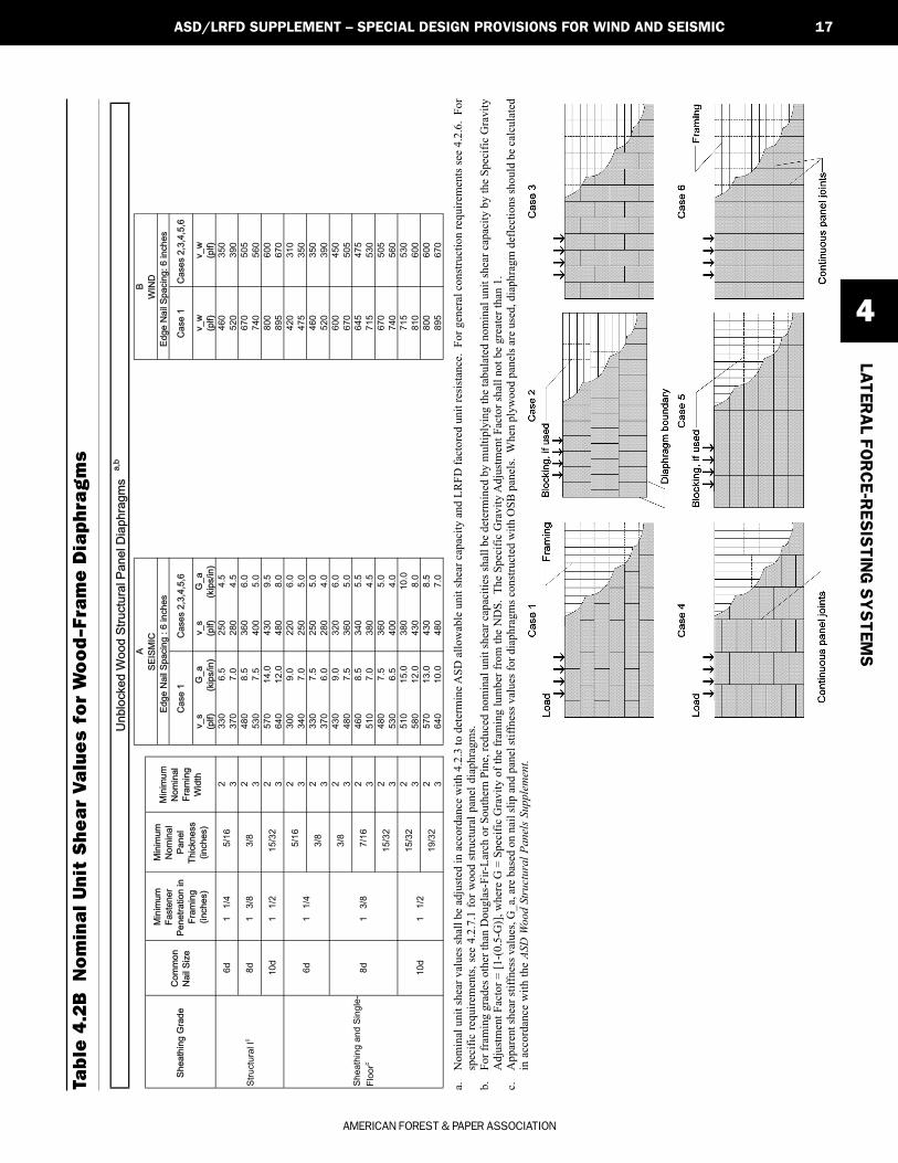
17ASD/LRFD SUPPLEMENT – SPECIAL DESIGN PROVISIONS FOR WIND AND SEISMIC
Tab
le 4
.2B
N
om
ina
l U
nit
Sh
ea
r V
alu
es
fo
r W
oo
d-F
ram
e D
iap
hra
gm
s
a.N
omin
al u
nit s
hear
val
ues s
hall
be a
djus
ted
in a
ccor
danc
e w
ith 4
.2.3
to d
eter
min
e ASD
allo
wab
le u
nit s
hear
cap
acity
and
LR
FD fa
ctor
ed u
nit r
esis
tanc
e. F
or g
ener
al c
onst
ruct
ion
requ
irem
ents
see
4.2.
6. F
orsp
ecifi
c re
quire
men
ts, s
ee 4
.2.7
.1 fo
r woo
d st
ruct
ural
pan
el d
iaph
ragm
s.b.
For f
ram
ing
grad
es o
ther
than
Dou
glas
-Fir-
Larc
h or
Sou
ther
n Pi
ne, r
educ
ed n
omin
al u
nit s
hear
cap
aciti
es sh
all b
e de
term
ined
by
mul
tiply
ing
the
tabu
late
d no
min
al u
nit s
hear
cap
acity
by
the
Spec
ific
Gra
vity
Adj
ustm
ent F
acto
r = [1
-(0.
5-G
)], w
here
G =
Spe
cific
Gra
vity
of t
he fr
amin
g lu
mbe
r fro
m th
e N
DS.
The
Spe
cific
Gra
vity
Adj
ustm
ent F
acto
r sha
ll no
t be
grea
ter t
han
1.c.
App
aren
t she
ar st
iffne
ss v
alue
s, G
_a, a
re b
ased
on
nail
slip
and
pan
el st
iffne
ss v
alue
s for
dia
phra
gms c
onst
ruct
ed w
ith O
SB p
anel
s. W
hen
plyw
ood
pane
ls a
re u
sed,
dia
phra
gm d
efle
ctio
ns sh
ould
be
calc
ulat
edin
acc
orda
nce
with
the
ASD
Woo
d St
ruct
ural
Pan
els
Supp
lem
ent.
v_
sG
_a
v_
sG
_a
v_
wv_
w
(plf)
(kip
s/in
)(p
lf)
(kip
s/in
)(p
lf)
(plf)
Ed
ge
Na
il S
pa
cin
g :
6 in
ch
es
Un
blo
cke
d W
oo
d S
tru
ctu
ral P
an
el D
iap
hra
gm
sa,b
Ed
ge
Na
il S
pa
cin
g:
6 in
ch
es
Co
mm
on
Na
il S
ize
B
WIN
D
Sh
ea
thin
g G
rad
e
A
SE
ISM
IC
Table
4.2
(continued)
Nom
inal U
nit S
hear
Valu
es for
Wood-F
ram
e D
iaphra
gm
s
Min
imu
m
No
min
al
Pa
ne
l
Th
ickn
ess
(in
ch
es)
Min
imu
m
No
min
al
Fra
min
g
Wid
th
Ca
se
s 2
,3,4
,5,6
Ca
se
1C
ase
1C
ase
s 2
,3,4
,5,6
Min
imu
m
Fa
ste
ne
r
Pe
ne
tra
tio
n in
Fra
min
g
(in
ch
es)
v_
sG
_a
v_
sG
_a
v_
wv_
w
(plf)
(kip
s/in
)(p
lf)
(kip
s/in
)(p
lf)
(plf)
23
30
6.5
25
04
.54
60
35
0
33
70
7.0
28
04
.55
20
39
0
24
80
8.5
36
06
.06
70
50
5
35
30
7.5
40
05
.07
40
56
0
25
70
14
.04
30
9.5
80
06
00
36
40
12
.04
80
8.0
89
56
70
23
00
9.0
22
06
.04
20
31
0
33
40
7.0
25
05
.04
75
35
0
23
30
7.5
25
05
.04
60
35
0
33
70
6.0
28
04
.05
20
39
0
24
30
9.0
32
06
.06
00
45
0
34
80
7.5
36
05
.06
70
50
5
24
60
8.5
34
05
.56
45
47
5
35
10
7.0
38
04
.57
15
53
0
24
80
7.5
36
05
.06
70
50
5
35
30
6.5
40
04
.07
40
56
0
25
10
15
.03
80
10
.07
15
53
0
35
80
12
.04
30
8.0
81
06
00
25
70
13
.04
30
8.5
80
06
00
36
40
10
.04
80
7.0
89
56
70
Ed
ge
Na
il S
pa
cin
g :
6 in
ch
es
Un
blo
cke
d W
oo
d S
tru
ctu
ral P
an
el D
iap
hra
gm
sa
,b
Ed
ge
Na
il S
pa
cin
g:
6 in
ch
es
Co
mm
on
Na
il S
ize
B
WIN
D
1
1/2
Sh
ea
thin
g G
rad
e
1
1/4
1
3/8
1
1/2
1
1/4
1
3/8
7/1
6
15
/32
15
/32
19
/32
3/8
Sh
ea
thin
g a
nd
Sin
gle
-
Flo
orc
6d
8d
Str
uctu
ral Ic
6d
10
d
8d
10
d
A
SE
ISM
IC
5/1
6
3/8
5/1
6
3/8
15
/32
Ta
ble
4.2
(co
ntin
ue
d)
No
min
al U
nit S
he
ar
Va
lue
s f
or
Wo
od
-Fra
me
Dia
ph
rag
ms
Min
imu
m
No
min
al
Pa
ne
l
Th
ickn
ess
(in
ch
es)
Min
imu
m
No
min
al
Fra
min
g
Wid
th
Ca
se
s 2
,3,4
,5,6
Ca
se
1C
ase
1C
ase
s 2
,3,4
,5,6
Min
imu
m
Fa
ste
ne
r
Pe
ne
tra
tio
n in
Fra
min
g
(in
ch
es)
Seismic C4 Draft.pmd 7/26/2002, 10:43 AM17
AMERICAN WOOD COUNCIL
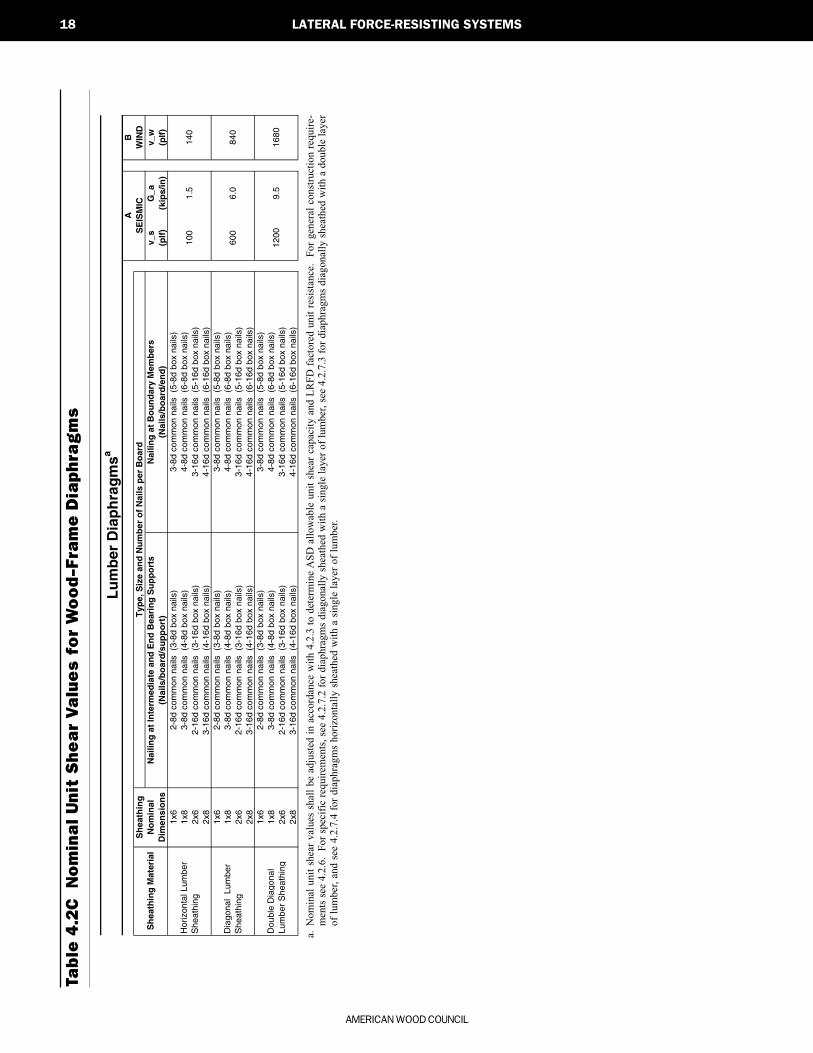
18 LATERAL FORCE-RESISTING SYSTEMS
Tab
le 4
.2C
N
om
ina
l U
nit
Sh
ea
r V
alu
es
fo
r W
oo
d-F
ram
e D
iap
hra
gm
s
a.N
omin
al u
nit
shea
r va
lues
sha
ll be
adj
uste
d in
acc
orda
nce
with
4.2
.3 t
o de
term
ine
ASD
allo
wab
le u
nit
shea
r ca
paci
ty a
nd L
RFD
fac
tore
d un
it re
sist
ance
. Fo
r ge
nera
l co
nstr
uctio
n re
quir
e-m
ents
see
4.2
.6.
For
spec
ific
req
uire
men
ts, s
ee 4
.2.7
.2 f
or d
iaph
ragm
s di
agon
ally
she
athe
d w
ith a
sin
gle
laye
r of
lum
ber,
see
4.2.
7.3
for
diap
hrag
ms
diag
onal
ly s
heat
hed
with
a d
oubl
e la
yer
of l
umbe
r, an
d se
e 4.
2.7.
4 fo
r di
aphr
agm
s ho
rizo
ntal
ly s
heat
hed
with
a s
ingl
e la
yer
of l
umbe
r.
BW
IND
v_s
G_a
v_w
(plf
)(k
ips/
in)
(plf
)1x
61x
82x
62x
81x
61x
82x
62x
81x
61x
82x
62x
8
Lu
mb
er D
iap
hra
gm
sa
AS
EIS
MIC
600
6.0
100
1.5
Sh
eath
ing
Mat
eria
lS
hea
thin
g
No
min
al
Dim
ensi
on
s
Typ
e, S
ize
and
Nu
mb
er o
f N
ails
per
Bo
ard
Nai
ling
at
Inte
rmed
iate
an
d E
nd
Bea
rin
g S
up
po
rts
Nai
ling
at
Bo
un
dar
y M
emb
ers
(Nai
ls/b
oar
d/s
up
po
rt)
(Nai
ls/b
oar
d/e
nd
)
140
840
1200
9.5
1680
3-16
d co
mm
on n
ails
(4-
16d
box
nails
)
Hor
izon
tal L
umbe
r S
heat
hin g
2-8d
com
mon
nai
ls (
3-8d
box
nai
ls)
3-8d
com
mon
nai
ls (
5-8d
box
nai
ls)
3-8d
com
mon
nai
ls (
4-8d
box
nai
ls)
4-8d
com
mon
nai
ls (
6-8d
box
nai
ls)
2-16
d co
mm
on n
ails
(3-
16d
box
nails
)3-
16d
com
mon
nai
ls (
5-16
d bo
x na
ils)
4-16
d co
mm
on n
ails
(6-
16d
box
nails
)
3-16
d co
mm
on n
ails
(4-
16d
box
nails
)4-
16d
com
mon
nai
ls (
6-16
d bo
x na
ils)
Dia
gona
l Lu
mbe
r S
heat
hin g
2-8d
com
mon
nai
ls (
3-8d
box
nai
ls)
3-8d
com
mon
nai
ls (
5-8d
box
nai
ls)
3-8d
com
mon
nai
ls (
4-8d
box
nai
ls)
4-8d
com
mon
nai
ls (
6-8d
box
nai
ls)
2-16
d co
mm
on n
ails
(3-
16d
box
nails
)3-
16d
com
mon
nai
ls (
5-16
d bo
x na
ils)
4-16
d co
mm
on n
ails
(6-
16d
box
nails
)
Dou
ble
Dia
gona
l Lu
mbe
r S
heat
hin g
2-8d
com
mon
nai
ls (
3-8d
box
nai
ls)
3-8d
com
mon
nai
ls (
5-8d
box
nai
ls)
3-8d
com
mon
nai
ls (
4-8d
box
nai
ls)
4-8d
com
mon
nai
ls (
6-8d
box
nai
ls)
2-16
d co
mm
on n
ails
(3-
16d
box
nails
)3-
16d
com
mon
nai
ls (
5-16
d bo
x na
ils)
3-16
d co
mm
on n
ails
(4-
16d
box
nails
)
Seismic C4 Draft.pmd 6/11/02, 6:35 PM18

AMERICAN FOREST & PAPER ASSOCIATION
LATER
AL FO
RC
E-R
ES
ISTIN
G S
YS
TEM
S
4
19ASD/LRFD SUPPLEMENT – SPECIAL DESIGN PROVISIONS FOR WIND AND SEISMIC
4.3 Wood Shear Walls
4.3.1 Application Requirements
Wood shear walls are permitted to resist horizontalforces provided the deflection of the shear wall, as deter-mined by calculations, tests, or analogies drawn therefrom,does not exceed the permissible deflection.
4.3.2 Deflection
Permissible deflection shall be that deflection up towhich the shear wall and any attached distributing or re-sisting element will maintain its structural integrity underdesign load conditions and continue to support design loadswithout danger to occupants of the structure.
Calculations of shear wall deflection shall account forbending and shear deflections, fastener deformation, an-chorage slip, and other contributing sources of deflection.
The shear wall deflection, δsw, is permitted to be cal-culated by use of the following equation:
38
1000a
sw
a
hh h
EAb G b
∆ν νδ = + + (4.3-1)
where:
b = Shear wall length, ft.
∆a
= Total vertical elongation of wall anchorage
system (including fastener slip, device
elongation, rod elongation, etc.), at the induced
unit shear in the shear wall, in.
E = Modulus of elasticity of end posts, psi
A = Area of end post cross-section, in.2
Ga
= Apparent shear wall shear stiffness from nail
slip and panel shear deformation, (from Column
A, Table 4.3), kips/in.
h = Shear wall height, ft.
ν = Induced unit shear, lbs./ft.
δsw
= Maximum shear wall deflection determined by
elastic analysis, in.
Alternatively, for wood structural panel shear walls,deflection is permitted to be calculated using a rationalanalysis where apparent shear stiffness accounts for panelshear deformation and non-linear nail slip in the sheath-ing to framing connection.
4.3.2.1 Deflection of Perforated Shear Walls: The de-flection of a perforated shear wall shall be calculated inaccordance with Section 4.3.2, where ν is equal to νmax inEquation 4.3-1 and b is taken as the sum of the perforatedshear wall segments ∑Li.
4.3.3 Shear Capacities
The ASD allowable unit shear capacity shall be de-termined by dividing the nominal unit shear capacity by asafety factor of 2.0. No further increases shall be permit-ted. The LRFD factored unit resistance shall be determinedby multiplying the nominal unit shear capacity by a resis-tance factor, φD, of 0.65.
4.3.3.1 Tabulated Nominal Unit Shear Capacities:Tabulated nominal unit shear capacities for seismic designare provided in Column A of Tables 4.3A, B, and C and forwind design in Column B of Tables 4.3A, B, and C.
4.3.3.2 Summing Shear Capacities: For shear wallssheathed with the same construction and materials on op-posite sides of the same wall, the combined nominal unitshear capacity, νsc or νwc, shall be permitted to be taken astwice the nominal unit shear capacity for an equivalentshear wall sheathed on one side.
For seismic design of shear walls sheathed with thesame construction and materials on opposite sides of ashear wall, the shear wall deflection shall be calculatedusing the combined apparent shear wall shear stiffness,Gac and the combined nominal unit shear capacity, νsc,shall be calculated using the following equations:
1 2ac a aG G G= + (4.3-2)
V K Gsc ac= min (4.3-3)
where:
Gac
= Combined apparent shear wall shear stiffness
of two-sided shear wall, kips/in.
Ga1
= Apparent shear wall shear stiffness for side 1,
kips/in. (from Column A, Table 4.3)
Ga2
= Apparent shear wall shear stiffness for side 2,
kips/in. (from Column A, Table 4.3)
Kmin
= Minimum ratio of νs1
/Ga1
or νs2
/Ga2
νs1
= Nominal unit shear capacity for side 1, lbs./ft.
(from Column A, Table 4.3)
Seismic C4 Draft.pmd 6/11/02, 6:35 PM19

AMERICAN WOOD COUNCIL
20 LATERAL FORCE-RESISTING SYSTEMS
νs2
= Nominal unit shear capacity for side 2, lbs./ft.
(from Column A, Table 4.3)
νsc
= Combined nominal unit shear capacity of two-
sided shear wall for seismic design, lbs./ft.
Nominal unit shear capacities for shear walls sheathedwith dissimilar materials on the same side of the wall arenot cumulative. For shear walls sheathed with dissimilarmaterials on opposite sides, the combined nominal unitshear capacity, νsc or νwc, shall be either two times thesmaller nominal unit shear capacity or the larger nominalunit shear capacity, whichever is greater.
Exception: For wind design, the combined nomi-nal unit shear capacity νwc, of shear walls sheathedwith a combination of wood structural panels andgypsum wall-board on opposite sides shall equalthe sum of the sheathing capacities of each sideseparately.
4.3.3.3 Summing Shear Wall Lines: The nominalshear capacity for shear walls in a line utilizing shear wallssheathed with the same construction and materials, shallbe permitted to be combined.
4.3.3.4 Shear Capacity of Perforated Shear Walls: Thenominal shear capacity of a perforated shear wall shall betaken as the nominal unit shear capacity multiplied by thesum of the shear wall segment lengths, ∑Li, and the ap-propriate shear capacity adjustment factor, Co, from Table4.3.3.4.
1 The maximum opening height shall be taken as the maximum opening clear height in a perforated shear wall. Where areas above and belowan opening remain unsheathed, the height of the opening shall be defined as the height of the wall.
2 The sum of the lengths of the perforated shear wall segments divided by the total length of the perforated shear wall.
o
WALL HEIGHT, h
MAXIMUM OPENING HEIGHT 1
h/3 h/2 2h/3 5h/6 h
8' Wall 2'-8" 4'-0" 5'-4" 6'-8" 8'-0"10' Wall 3'-4" 5'-0" 6'-8" 8'-4" 10'-0"
Percent Full-Height Sheathing 2 Effective Shear Capacity Ratio
10%20%30%40%50%60%70%80%90%
100%
1.001.001.001.001.001.001.001.001.001.00
0.690.710.740.770.800.830.870.910.951.00
0.530.560.590.630.670.710.770.830.911.00
0.430.450.490.530.570.630.690.770.871.00
0.360.380.420.450.500.560.630.710.831.00
Table 4.3.3.4 Shear Capacity Adjustment Factor, Co
Seismic C4 Draft.pmd 6/11/02, 6:35 PM20
AMERICAN FOREST & PAPER ASSOCIATION
LATER
AL FO
RC
E-R
ES
ISTIN
G S
YS
TEM
S
4
21ASD/LRFD SUPPLEMENT – SPECIAL DESIGN PROVISIONS FOR WIND AND SEISMIC
4.3.4 Shear Wall Aspect Ratios
Size and shape of shear walls shall be limited to theaspect ratios in Table 4.3.4.
Table 4.3.4 Maximum Shear WallAspect Ratios
Shear Wall MaximumSheathing Type h/bs RatioWood structural panels, all edges nailed 3½:11
Particleboard, all edges nailed 2:1Diagonal Sheathing, conventional 2:1Gypsum wallboard2 2:1Portland Cement Plaster2 2:1Fiberboard 1½:1
1 For design to resist seismic forces, the shear wall aspect ratio shall notexceed 2:1 unless the nominal unit shear capacity is multiplied by 2bs/h. Inno case shall the aspect ratio exceed 3½:1.
2 Walls having aspect ratios exceeding 1½:1 shall be blocked.
4.3.4.1 Aspect Ratio of Perforated Shear Wall Seg-ments: The aspect ratio limitations of 4.3.4 shall apply toperforated shear wall segments within a perforated shearwall. For design to resist seismic forces, the nominal shearcapacity of the perforated shear wall shall be multipliedby 2bs/h when the aspect ratio of any perforated shearwall segment included in the sum of shear wall segmentlengths, ∑Li, is greater than 2:1, but does not exceed 3½:1.Portions of walls with aspect ratios in excess of 3½:1 shallnot be counted in the sum of shear wall segments.
4.3.5 Shear Walls With Openings
The provisions of this section shall apply to the de-sign of shear walls with openings. Where framing andconnections around the openings are designed for forcetransfer around the openings the provisions of 4.3.5.1 shallapply. Where framing and connections around the open-ing are not designed for force transfer around the openingsthe provisions of 4.3.5.2 shall apply.
4.3.5.1 Force Transfer Around Openings: Whereshear walls with openings are designed for force transferaround the openings, the aspect ratio limitations of 4.3.4shall apply to the overall shear wall including openingsand to each wall pier at the sides of an opening. The heightof a wall pier shall be defined as the clear height of thepier at the side of an opening. The length of a wall piershall be defined as the sheathed length of the pier. Designfor force transfer shall be based on a rational analysis.The length of a wall pier shall not be less than 2 feet.
4.3.5.2 Perforated Shear Walls: Where wood struc-tural panel shear walls with openings are not designed forforce transfer around the opening, they shall be designedas perforated shear walls. The following limitations shallapply:
a. A perforated shear wall segment shall be lo-cated at each end of a perforated shear wall.Openings shall be permitted to occur beyondthe ends of the perforated shear wall, how-ever the length of such openings shall not beincluded in the length of the perforated shearwall.
b. The nominal unit shear capacity shall not ex-ceed 2,000 plf.
c. Where out of plane offsets occur, portions ofthe wall on each side of the offset shall beconsidered as separate perforated shear walls.
d. Collectors for shear transfer shall be providedthrough the full length of the perforated shearwall.
e. A perforated shear wall shall have uniformtop of wall and bottom of wall elevations.Perforated shear walls not having uniformelevations shall be designed by other meth-ods.
f. Perforated shear wall height, h, shall not ex-ceed 20 feet.
4.3.6 Construction Requirements
4.3.6.1 Framing Requirements: All framing used forshear wall construction shall be 2x nominal or larger mem-bers. Shear wall boundary elements, such as end posts,shall be provided to transmit the design tension and com-pression forces. Shear wall sheathing shall not be used tosplice boundary elements. End posts (studs or columns)shall be framed to provide full end bearing.
a. Tension and Compression Chords: Tensionforce, T, and a compression force, C, result-ing from shear wall overturning forces at eachstory level shall be calculated in accordancewith the following:
T C h= = ν (4.3-4)
where:
C = Compression chord force, lbs.
h = Shear wall height, ft.
T = Tension chord force, lbs.
ν = Induced unit shear, lbs./ft.
Seismic C4 Draft.pmd 6/11/02, 6:35 PM21
AMERICAN WOOD COUNCIL
22 LATERAL FORCE-RESISTING SYSTEMS
Each end of each perforated shear wall shall be de-signed for a tension force, T, and a compression force, C.Each end of each perforated shear wall segment shall bedesigned for a compression force, C, in each segment.For perforated shear walls, the values for T and C result-ing from shear wall overturning forces at each story levelshall be calculated in accordance with the following:
T CVh
C Lo i
= =∑ (4.3-5)
where:
Co
= Shear capacity adjustment factor from Table
4.3.3.4
V = Induced shear force in perforated shear wall, lbs.
∑Li
= Sum of perforated shear wall segment lengths,
ft.
4.3.6.2 Sheathing: Shear walls shall be sheathed withapproved materials. Sheathing nails or other approvedsheathing connectors shall be driven flush with the sur-face of the sheathing. Details on sheathing types andthicknesses for commonly used shear wall assemblies areprovided in 4.3.7 and Tables 4.3A, B, and C.
4.3.6.3 Fasteners: Sheathing shall be attached to fram-ing using approved fasteners. Details on type, size, andspacing of mechanical fasteners in commonly used shearwall assemblies are provided in 4.3.7 and Tables 4.3A, B,and C.
a. Adhesives: Adhesive attachment of shear wallsheathing is not permitted as a substitute formechanical fasteners. Approved adhesive at-tachment systems shall be permitted in SeismicDesign Categories A and B where R = 1.5 andΩ0 = 2.5 unless other values are approved. InSeismic Design Categories C-F, adhesive at-tachment of shear wall sheathing is notpermitted.
4.3.6.4 Shear Wall Anchorage and Load Path: De-sign of shear wall anchorage and load path shall conformto the requirements of this section, or shall be calculatedusing principles of mechanics.
a. Anchorage for In-plane Shear: Connectionsshall be provided to transfer the induced unitshear force, ν, into and out of each shear wall.(1) In-plane Shear Anchorage for Perforated
Shear Walls: The maximum induced unitshear force, νmax, transmitted into the topof a perforated shear wall, out of the baseof the perforated shear wall at full heightsheathing, and into collectors (drag struts)
connecting shear wall segments, shall becalculated in accordance with the follow-ing:
νmax =∑V
C Lo i(4.3-6)
b. Uplift Anchorage at Shear Wall Ends: Wherethe dead load stabilizing moment is not suffi-cient to prevent uplift due to overturningmoments on the wall (from 4.3.6.1a), an an-choring device shall be provided at the endof each shear wall.(1) Uplift Anchorage for Perforated Shear
Walls: In addition to the requirements of4.3.6.4.b, perforated shear wall bottomplates at full height sheathing shall be an-chored for a uniform uplift force, t, equalto the unit shear force, ν, determined inSection 4.3.6.4.a.(1) or calculated by ra-tional analysis.
c. Anchor Bolts: Foundation anchor bolts shallhave a steel plate washer under each nut notless than 2½" x 2½" x ¼". The plate washershall extend to within ½" of the edge of thebottom plate on the sheathed side.
d. Load Path: A load path to the foundation shallbe provided for uplift, shear, and compres-sion forces. Elements resisting shear wallforces contributed by multiple stories shallbe designed for the sum of forces contributedby each story.
4.3.7 Shear Wall Systems
4.3.7.1 Wood Structural Panel Shear Walls: Shearwalls sheathed with wood structural panel sheathing shallbe permitted to be used to resist seismic and wind forces.The size and spacing of fasteners at shear wall bound-aries, panel edges, and intermediate supports shall be asprovided in Table 4.3A. The shear wall shall be constructedas follows:
a. Panels installed either horizontally or verti-cally with panel joints occurring overcommon studs or blocking. Panels not lessthan 4 ft. x 8 ft. except that a single panelwith a minimum dimension of 1 foot is per-mitted if it is fully blocked and nailed.
b. Nails spaced not less than 3/8 inch from edgesand ends of panels, studs, blocking, and topand bottom plates. Maximum nail spacing
Seismic C4 Draft.pmd 6/11/02, 6:36 PM22

AMERICAN FOREST & PAPER ASSOCIATION
LATER
AL FO
RC
E-R
ES
ISTIN
G S
YS
TEM
S
4
23ASD/LRFD SUPPLEMENT – SPECIAL DESIGN PROVISIONS FOR WIND AND SEISMIC
of 6 inches along intermediate framing mem-bers for 3/8-inch and 7/16-inch panelsinstalled on studs spaced 24 inches o.c. Maxi-mum nail spacing along intermediate framingof 12 inches for other conditions.
c. 2x or wider framing at adjoining panel edgesexcept that 3x or wider framing and staggerednailing are required where:(1) nails are spaced 2 inches o.c., or(2) 10d nails having penetration into framing
of more than 1-1/2 inches are spaced 3inches o.c., or less, or
(3) nominal unit shear capacity exceeds 700plf in seismic Design Category D, E, or F.
d. Maximum stud spacing of 24 inches.e. Wood structural panels shall conform to the
requirements for its type in DOC PS1 or PS2.4.3.7.2 Particleboard Shear Walls: Shear walls
sheathed with particleboard sheathing shall be permittedto be used to resist wind forces and seismic forces in Seis-mic Design Categories A, B, and C. The size and spacingof fasteners at shear wall boundaries, panel edges, andintermediate supports shall be as provided in Table 4.3A.The shear wall shall be constructed as follows:
a. Panels installed either horizontally or verti-cally with panel joints occurring overcommon studs or blocking. Panels not lessthan 4 feet x 8 feet except that a single panelwith a minimum dimension of 1 foot is per-mitted if it is fully blocked and nailed.
b. Nails spaced not less than 3/8 inch from edgesand ends of panels, studs, blocking, and topand bottom plates. Maximum nail spacingof 6 inches along intermediate framing mem-bers for 3/8-inch panels installed on studsspaced 24 inches o.c. Maximum nail spac-ing along intermediate framing of 12 inchesfor other conditions.
c. 2x or wider framing at adjoining panel edges.d. Maximum stud spacing of 24 inches.e. Particleboard shall conform to ANSI A208.1.4.3.7.3 Fiberboard Shear Walls: Shear walls sheathed
with fiberboard sheathing shall be permitted to be used toresist wind forces and seismic forces in Seismic DesignCategories A, B, and C. The size and spacing of fastenersat shear wall boundaries, panel edges, and intermediatesupports shall be as provided in Table 4.3A. The shearwall shall be constructed as follows:
a. 4 feet x 8 feet fiberboard sheathing shall beapplied vertically (long dimension parallel to
studs) with panel joints occurring over com-mon studs or blocking.
b. Nails spaced not less than 3/8 inch from edgesand ends of panels, studs, blocking, and topand bottom plates. Maximum nail spacing 6inches along intermediate framing members.
c. 2x or wider framing at adjoining panel edges.d. Maximum stud spacing of 16 inches.e. Minimum length of galvanized roofing nails
is 1½" for ½ inch thick sheathing and 1¾"for 25/32 inch thick sheathing.
f. Fiberboard sheathing shall conform to eitherAHA 194.1 or ASTM C208.
4.3.7.4 Gypsum Wallboard, Gypsum Veneer Base,Water-Resistant Backing Board, Gypsum Sheathing, Gyp-sum Lath and Plaster, or Portland Cement Plaster ShearWalls: Shear walls sheathed with gypsum wallboard, gyp-sum veneer base, water-resistant backing board, gypsumsheathing, gypsum lath and plaster, or portland cementplaster shall be permitted to be used to resist wind forcesand seismic forces in Seismic Design Categories A-D. Endjoints of adjacent courses of gypsum wallboard or sheath-ing shall not occur over the same stud. The size and spacingof fasteners at shear wall boundaries, panel edges, andintermediate supports shall be as provided in Table 4.3B.Nails shall be spaced not less than 3/8 inch from edgesand ends of panels, studs, blocking, and top and bottomplates. Wood framing shall be 2x or wider.
a. Gypsum Wallboard, Gypsum Veneer Base,Water-Resistant Backing Board: Gypsumwallboard, gypsum veneer base, or water-resistant backing board shall be appliedparallel or perpendicular to studs. Gypsumwallboard shall conform to ASTM C36 andshall be installed in accordance with ASTMC 840. Gypsum veneer base shall conformto ASTM C 588 and shall be installed in ac-cordance with ASTM C 844. Water-resistantbacking board shall conform to ASTM C630and shall be installed in accordance withASTM C 840.
b. Gypsum Sheathing: Four-foot-wide pieces ofgypsum sheathing shall be applied parallel orperpendicular to studs. Two-foot-wide piecesof gypsum sheathing shall be applied perpen-dicular to the studs. Gypsum sheathing shallconform to ASTM C79 and shall be installedin accordance with ASTM C 1280.
c. Gypsum Lath and Plaster: Gypsum lath shallbe applied perpendicular to the studs. Gyp-sum lath shall conform to ASTM C37 and
Seismic C4 Draft.pmd 6/11/02, 6:36 PM23

AMERICAN WOOD COUNCIL
24 LATERAL FORCE-RESISTING SYSTEMS
shall be installed in accordance with ASTMC 841. Gypsum plaster shall conform to therequirements of ASTM C 28.
d. Expanded Metal or Woven Wire Lath andPortland Cement: Expanded metal or wovenwire lath and portland cement shall conformto ASTM C847, ASTM 1032, and ASTM C150 and shall be installed in accordance withASTM C 926 and ASTM C 1063. Metal lathand lath attachments shall be of corrosion-resistant material.
4.3.7.5 Shear Walls Diagonally Sheathed with Single-Layer of Lumber: Single diagonally sheathed lumber shearwalls are permitted to be used to resist wind forces andseismic forces in Seismic Design Catergories A, B, C, andD. Single diagonally sheathed lumber shear walls shall beconstructed of minimum 1-inch thick nominal sheathingboards laid at an angle of approximately 45° to the sup-ports. End joints in adjacent boards shall be separated byat least one stud space and there shall be at least two boardsbetween joints on the same support. Nailing of diagonallysheathed lumber shear walls shall be in accordance withTable 4.3C.
4.3.7.6 Shear Walls Diagonally Sheathed with Double-Layer of Lumber: Double diagonally sheathed lumbershear walls are permitted to be used to resist wind forcesand seismic forces in Seismic Design Categories A, B, C,and D. Double diagonally sheathed lumber shear wallsshall be constructed of two layers of 1-inch thick nominaldiagonal sheathing boards laid perpendicular to each other
on the same face of the supporting members. Nailing ofdiagonally sheathed lumber shear walls shall be in accor-dance with Table 4.3C.
4.3.7.7 Shear Walls Horizontally Sheathed withSingle-Layer of Lumber: Horizontally sheathed lumbershear walls are permitted to be used to resist wind forcesand seismic forces in Seismic Design Categories A, B,and C. Horizontally sheathed lumber shear walls shall beconstructed of minimum 1-inch thick nominal sheathingboards applied perpendicular to the supports. End jointsin adjacent boards shall be separated by at least one studspace and there shall be at least two boards between jointson the same support. Nailing of horizontally sheathedlumber shear walls shall be in accordance with Table 4.3C.
4.3.7.8 Shear Walls Sheathed with Vertical Board Sid-ing: Vertical board siding shear walls are permitted to beused to resist wind forces and seismic forces in SeismicDesign Categories A, B, and C. Vertical board siding shearwalls shall be constructed of minimum 1-inch thick nomi-nal sheathing boards applied directly to studs and blocking.Nailing of vertical board siding shear walls shall be inaccordance with Table 4.3C.
Seismic C4 Draft.pmd 6/11/02, 6:36 PM24
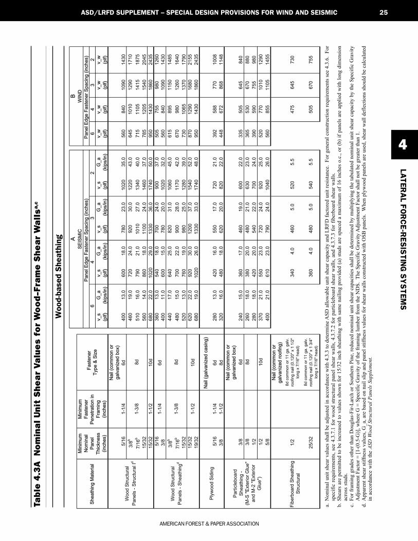
AMERICAN FOREST & PAPER ASSOCIATION
LATER
AL FO
RC
E-R
ES
ISTIN
G S
YS
TEM
S
4
25ASD/LRFD SUPPLEMENT – SPECIAL DESIGN PROVISIONS FOR WIND AND SEISMIC
Tab
le 4
.3A
N
om
ina
l U
nit
Sh
ea
r V
alu
es
fo
r W
oo
d-F
ram
e S
he
ar
Wa
lls
a,c
a.N
omin
al u
nit s
hear
val
ues
shal
l be
adju
sted
in a
ccor
danc
e w
ith 4
.3.3
to d
eter
min
e ASD
allo
wab
le u
nit s
hear
cap
acity
and
LR
FD fa
ctor
ed u
nit r
esis
tanc
e. F
or g
ener
al c
onst
ruct
ion
requ
irem
ents
see
4.3
.6.
For
spec
ific
requ
irem
ents
, see
4.3
.7.1
for w
ood
stru
ctur
al p
anel
she
ar w
alls
, 4.3
.7.2
for p
artic
lebo
ard
shea
r wal
ls, a
nd 4
.3.7
.3 fo
r fib
erbo
ard
shea
r wal
ls.
b.Sh
ears
are
per
mitt
ed to
be
incr
ease
d to
val
ues
show
n fo
r 15/
32 in
ch s
heat
hing
with
sam
e na
iling
pro
vide
d (a
) stu
ds a
re s
pace
d a
max
imum
of 1
6 in
ches
o.c
., or
(b) i
f pan
els
are
appl
ied
with
long
dim
ensi
onac
ross
stu
ds.
c.Fo
r fra
min
g gr
ades
oth
er th
an D
ougl
as-F
ir-La
rch
or S
outh
ern
Pine
, red
uced
nom
inal
uni
t she
ar c
apac
ities
sha
ll be
det
erm
ined
by
mul
tiply
ing
the
tabu
late
d no
min
al u
nit s
hear
cap
acity
by
the
Spec
ific
Gra
vity
Adj
ustm
ent F
acto
r = [1
-(0.
5-G
)], w
here
G =
Spe
cific
Gra
vity
of t
he fr
amin
g lu
mbe
r fro
m th
e N
DS.
The
Spe
cific
Gra
vity
Adj
ustm
ent F
acto
r sha
ll no
t be
grea
ter t
han
1.d.
App
aren
t she
ar st
iffne
ss v
alue
s, G
_a, a
re b
ased
on
nail
slip
and
pan
el st
iffne
ss v
alue
s for
shea
r wal
ls c
onst
ruct
ed w
ith O
SB p
anel
s. W
hen
plyw
ood
pane
ls a
re u
sed,
shea
r wal
l def
lect
ions
shou
ld b
e ca
lcul
ated
in a
ccor
danc
e w
ith th
e AS
D W
ood
Stru
ctur
al P
anel
s Su
pple
men
t.
Woo
d-ba
sed
She
athi
ng
64
32
v_s
G_a
v_s
G_a
v_s
G_a
v_s
G_a
v_w
v_w
v_w
v_w
(plf)
(kip
s/in)
(plf)
(kip
s/in)
(plf)
(kip
s/in)
(plf)
(kip
s/in)
(plf)
(plf)
(plf)
(plf)
Nail
(com
mon o
r
galv
aniz
ed b
ox)
5/1
61-1
/46d
400
13.0
600
18.0
780
23.0
1020
35.0
560
840
1090
1430
3/8
b460
19.0
720
24.0
920
30.0
1220
43.0
645
1010
1290
1710
7/1
6b
510
16.0
790
21.0
1010
27.0
1340
40.0
715
1105
1415
1875
15/3
2560
14.0
860
18.0
1100
24.0
1460
37.0
785
1205
1540
2045
15/3
21-1
/210d
680
22.0
1020
29.0
1330
36.0
1740
50.0
950
1430
1860
2435
5/1
6360
13.0
540
18.0
700
24.0
900
37.0
505
755
980
1260
3/8
400
11.0
600
15.0
780
20.0
1020
32.0
560
840
1090
1430
3/8
b440
17.0
640
25.0
820
31.0
1060
45.0
615
895
1150
1485
7/1
6b
480
15.0
700
22.0
900
28.0
1170
42.0
670
980
1260
1640
15/3
2520
13.0
760
19.0
980
25.0
1280
39.0
730
1065
1370
1790
15/3
2620
22.0
920
30.0
1200
37.0
1540
52.0
870
1290
1680
2155
19/3
2680
19.0
1020
26.0
1330
33.0
1740
48.0
950
1430
1860
2435
Nail
(galv
aniz
ed c
asin
g)
5/1
61-1
/46d
280
13.0
420
16.0
550
17.0
720
21.0
392
588
770
1008
3/8
1-1
/28d
320
16.0
480
18.0
620
20.0
820
22.0
448
672
868
1148
Nail
(com
mon o
r
galv
aniz
ed b
ox)
3/8
6d
240
15.0
360
17.0
460
19.0
600
22.0
335
505
645
840
3/8
8d
260
18.0
380
20.0
480
21.0
630
23.0
365
530
670
880
1/2
280
18.0
420
20.0
540
22.0
700
24.0
390
590
755
980
1/2
10d
370
21.0
550
23.0
720
24.0
920
25.0
520
770
1010
1290
5/8
400
21.0
610
23.0
790
24.0
1040
26.0
560
855
1105
1455
1/2
8d
co
mm
on
or
11
ga
. g
alv
.
roo
fin
g n
ail
(0.1
20
" x 1
1/2
"
lon
g x
7/1
6"
he
ad
)
340
4.0
460
5.0
520
5.5
475
645
730
25/3
28
d c
om
mo
n o
r 1
1 g
a.
ga
lv.
roo
fin
g n
ail
(0.1
20
" x 1
3/4
"
lon
g x
7/1
6"
he
ad
)
360
4.0
480
5.0
540
5.5
505
670
755
Wood S
tructu
ral
Panels
- S
heath
ing
d
Ply
wood S
idin
g
Nail
(com
mon o
r
galv
aniz
ed r
oofing)
1-1
/4
Wood S
tructu
ral
Panels
- S
tructu
ral Id
Fib
erb
oard
Sheath
ing -
Str
uctu
ral
Panel E
dge F
aste
ner
Spacin
g (
inches)
AS
EIS
MIC
64
32
Part
icle
board
Sheath
ing -
(M-S
"E
xte
rior
Glu
e"
and M
-2 "
Exte
rior
Glu
e")
WIN
D
F
aste
ner
Type &
Siz
e
Min
imum
Nom
inal
Panel
Thic
kness
(inches)
Sheath
ing M
ate
rial
B
Panel E
dge F
aste
ner
Spacin
g (
inches)
Min
imum
Faste
ner
Penetr
ation in
Fra
min
g
(inches)
1-3
/8
1-3
/8
1-1
/2
8d
10d
6d
8d
Seismic C4 Draft.pmd 7/26/2002, 11:46 AM25

AMERICAN WOOD COUNCIL
26 LATERAL FORCE-RESISTING SYSTEMS
Tab
le 4
.3B
N
om
ina
l U
nit
Sh
ea
r V
alu
es
fo
r W
oo
d-F
ram
e S
he
ar
Wa
lls
a
a.N
omin
al u
nit s
hear
val
ues
shal
l be
adju
sted
in a
ccor
danc
e w
ith 4
.3.3
to d
eter
min
e A
SD a
llow
able
uni
t she
ar c
apac
ity a
nd L
RFD
fac
tore
d un
it re
sist
ance
. Fo
r ge
nera
l con
stru
ctio
n re
quir
emen
ts s
ee 4
.3.6
. Fo
rsp
ecif
ic r
equi
rem
ents
, se
e 4.
3.7.
4.b.
Type
S o
r W
dry
wal
l scr
ews
shal
l con
form
to r
equi
rem
ents
of A
STM
C 1
002.
c.W
here
tw
o nu
mbe
rs a
re g
iven
for
max
imum
fas
tene
r ed
ge s
paci
ng, t
he f
irst
num
ber
deno
tes
fast
ener
spa
cing
at
the
edge
s an
d th
e se
cond
num
ber
deno
tes
fast
ener
spa
cing
in
the
fiel
d.
BW
IND
v_s
G_a
v_w
(plf
)(k
ips/
in)
(plf
)7"
24"
unbl
ocke
d15
04.
015
04"
24"
unbl
ocke
d22
06.
522
07"
16"
unbl
ocke
d20
05.
520
04"
16"
unbl
ocke
d25
07.
025
07"
16"
bloc
ked
250
6.5
250
4"16
"bl
ocke
d30
09.
030
08/
12"
16"
unbl
ocke
d12
03.
012
04/
16"
16"
bloc
ked
320
8.5
320
4/12
"24
"bl
ocke
d31
09.
531
08/
12"
16"
bloc
ked
140
4.0
140
6/12
"16
"bl
ocke
d18
05.
018
07"
24"
unbl
ocke
d23
06.
023
04"
24"
unbl
ocke
d29
08.
029
07"
16"
bloc
ked
290
7.5
290
4"16
"bl
ocke
d35
010
.035
08/
12"
16"
unbl
ocke
d14
04.
014
08/
12"
16"
bloc
ked
180
4.0
180
5/8"
Bas
e: 9
"
(Tw
o-P
ly)
Fac
e: 7
"
4"24
"bl
ocke
d35
010
.035
07"
16"
unbl
ocke
d20
05.
020
04/
7"
5.0
17.0
150
Gyp
sum
wal
lboa
rd,
gyps
um v
enee
r ba
se, o
r w
ater
-res
ista
nt g
ypsu
m
back
ing
boar
d
AS
EIS
MIC
500
1/2"
x 2
' x 8
'
500
150
16"
5/8"
Mat
eria
l T
hic
knes
s
No.
6 T
ype
S o
r W
dry
wal
l scr
ews
1-1/
4" lo
ng
Bas
e pl
y--6
d co
oler
(0.
092"
x 1
-7/8
" lo
ng, 1
/4"
head
) or
wal
lboa
rd n
ail (
0.09
15"
x
1-7/
8"
long
, 19/
64"
head
) or
0.1
20"n
ail x
1-3
/4"
long
, min
3/8
" he
adF
ace
ply-
-8d
cool
er (
0.11
3" x
2-3
8" lo
ng, 0
.281
" he
ad)
or
wal
lboa
rd n
ail (
0.11
3" x
2-3
/8"
long
, 3/8
" he
ad)
or 0
.120
" na
il x
2-3/
8" lo
ng, m
in 3
/8"
head
16"
0.12
0" n
ail x
1½
” lo
ng, 7
/16"
hea
d
Sh
eath
ing
Mat
eria
l
360
12.0
400
400
13.0
Exp
ande
d m
etal
or
wov
en
wire
lath
and
por
tland
ce
men
t pla
ster
16"
7/8"
6"
No.
6 T
ype
S o
r W
dry
wal
l scr
ews
1-1/
4" lo
ng
No.
6 T
ype
S o
r W
dry
wal
l scr
ews
1-1/
4" lo
ng
4"
Fas
ten
er T
ype
& S
izeb
6d c
oole
r (0
.092
" x
1-7/
8" lo
ng, 1
/4"
head
) or
wal
lboa
rd n
ail (
0.09
15"
x 1-
7/8"
long
, 19/
64"
head
) or
0.1
20"
nail
x 1-
3/4"
long
, min
3/8
" he
ad
No.
6 T
ype
S o
r W
dry
wal
l scr
ews
1-1/
4" lo
ng
Max
. Fas
ten
er
Ed
ge
Sp
acin
g c
0.1
20"
nail
x 1
3/4"
long
, 7/
16"
head
, dia
mon
d-po
int,
galv
aniz
ed
1/2"
Max
. Stu
d
Sp
acin
g
Gyp
sum
lath
, pla
in o
r pe
rfor
ated
3/8"
lath
and
1/
2" p
last
er
5/8"
x 4
'6d
gal
vani
zed
cool
er (
0.09
2" x
1-7
/8"
long
, 1/4
" he
ad)
or w
allb
oard
nai
l (0.
0915
" x
1-7/
8"
long
, 19/
64"
head
) or
0.1
20"
nail
x 1-
3/4"
long
, min
3/8
" he
ad
0.09
2"x
1-1/
8" lo
ng, 1
9/64
" he
ad, g
ypsu
m w
allb
oard
blu
ed n
ail o
r 0.
120"
nai
l x1
1/4"
long
, m
in 3
/8"
head
1/2"
x 4
'G
ypsu
m s
heat
hing
5d c
oole
r (0
.086
" x
1-5/
8" lo
ng, 1
5/64
" he
ad)
or w
allb
oard
nai
l (0.
086"
x 1
-5/8
" lo
ng, 9
/32"
he
ad)
or 0
.120
" na
il x
1-1/
2" lo
ng, m
in 3
/8"
head
200
360
unbl
ocke
d
unbl
ocke
d20
06.
5
bloc
ked
unbl
ocke
d
5"16
"
bloc
ked
16"
Gyp
sum
and
Cem
ent
Pla
ster
Seismic C4 Draft.pmd 6/11/02, 6:36 PM26

AMERICAN FOREST & PAPER ASSOCIATION
LATER
AL FO
RC
E-R
ES
ISTIN
G S
YS
TEM
S
4
27ASD/LRFD SUPPLEMENT – SPECIAL DESIGN PROVISIONS FOR WIND AND SEISMIC
Tab
le 4
.3C
N
om
ina
l U
nit
Sh
ea
r V
alu
es
fo
r W
oo
d-F
ram
e S
he
ar
Wa
lls
a
a.N
omin
al u
nit s
hear
val
ues
shal
l be
adju
sted
in a
ccor
danc
e w
ith 4
.3.3
to d
eter
min
e A
SD a
llow
able
uni
t she
ar c
apac
ity a
nd L
RFD
fac
tore
d un
it re
sist
ance
. Fo
r ge
nera
l con
stru
ctio
n re
quir
emen
ts s
ee 4
.3.6
. Fo
rsp
ecif
ic r
equi
rem
ents
, see
4.3
.7.5
- 4
.3.7
.8.
Lum
ber
She
ar W
alls
BW
IND
v_s
G_a
v_w
(plf
)(k
ips/
in)
(plf
)1x
6 &
sm
alle
r1x
8 &
larg
er1x
6 &
sm
alle
r1x
8 &
larg
er1x
6 &
sm
alle
r1x
8 &
larg
er1x
6 &
sm
alle
r1x
8 &
larg
er
Dia
gona
l Lu
mbe
r S
heat
hing
Hor
izon
tal L
umbe
r S
heat
hing
Sh
eath
ing
N
om
inal
D
imen
sio
ns
Ver
tical
Lum
ber
Sid
ing
3-8d
com
mon
nai
ls (
5-8d
box
nai
ls)
Nai
ling
at
Inte
rmed
iate
Stu
ds
Nai
ling
at
Sh
ear
Wal
l Bo
un
dar
y M
emb
ers
(nai
ls/b
oar
d/s
up
po
rt)
(nai
ls/b
oar
d/e
nd
)
Dou
ble
Dia
gona
l Lum
ber
She
athi
ng
Sh
eath
ing
Mat
eria
l
A
3-8d
com
mon
nai
ls (
4-8d
box
nai
ls)
4-8d
com
mon
nai
ls (
6-8d
box
nai
ls)
Typ
e, S
ize
and
Nu
mb
er o
f N
ails
per
Bo
ard
2-8d
com
mon
nai
ls (
3-8d
box
nai
ls)
SE
ISM
IC
1200
10.0
140
100
1.5
840
6.0
3-8d
com
mon
nai
ls (
5-8d
box
nai
ls)
2-8d
com
mon
nai
ls (
3-8d
box
nai
ls)
3-8d
com
mon
nai
ls (
5-8d
box
nai
ls)
600
3-8d
com
mon
nai
ls (
4-8d
box
nai
ls)
4-8d
com
mon
nai
ls (
6-8d
box
nai
ls)
2-8d
com
mon
nai
ls (
3-8d
box
nai
ls)
3-8d
com
mon
nai
ls (
5-8d
box
nai
ls)
3-8d
com
mon
nai
ls (
4-8d
box
nai
ls)
4-8d
com
mon
nai
ls (
6-8d
box
nai
ls)
1680
3-8d
com
mon
nai
ls (
4-8d
box
nai
ls)
4-8d
com
mon
nai
ls (
6-8d
box
nai
ls)
125
901.
02-
8d c
omm
on n
ails
(3-
8d b
ox n
ails
)
Seismic C4 Draft.pmd 6/11/02, 6:36 PM27

AMERICAN WOOD COUNCIL
LATERAL FORCE-RESISTING SYSTEMS28
Seismic C4 Draft.pmd 6/11/02, 6:36 PM28
AMERICAN FOREST & PAPER ASSOCIATION
29
REFERENCES
ASD/LRFD SUPPLEMENT – SPECIAL DESIGN PROVISIONS FOR WIND AND SEISMIC
5
Seismic C5 Draft.pmd 4/22/02, 8:25 AM29

AMERICAN WOOD COUNCIL
30 REFERENCES
References
13. ASTM C840-01, Standard Specification for Appli-cation and Finishing of Gypsum Board, ASTM, WestConshocken, PA, 2001.
14. ASTM C841-99, Standard Specification for Instal-lation of Interior Lathing and Furring, ASTM, WestConshocken, PA, 1999.
15. ASTM C844-99, Standard Specification for Appli-cation of Gypsum Base to Receive Gypsum VeneerPlaster, ASTM, West Conshocken, PA, 1999.
16. ASTM C847-95(2000), Standard Specification forMetal Lath, ASTM, West Conshocken, PA, 2000.
17. ASTM C926-98a, Standard Specification for Appli-cation of Portland Cement Based Plaster, ASTM,West Conshocken, PA, 1998.
18. ASTM C1032-96, Standard Specification for WovenWire Plaster Base, ASTM, West Conshocken, PA,1996.
19. ASTM C1063-99, Standard Specification for Instal-lation of Lathing and Furring to Receive Interior andExterior Portland Cement-Based Plaster, ASTM,West Conshocken, PA, 1999.
20. ASTM C1280-99, Standard Specification for Appli-cation of Gypsum Sheathing, ASTM, WestConshocken, PA, 1999.
21. PS1-95 Construction and Industrial Plywood, UnitedStates Department of Commerce, National Instituteof Standards and Technology, Gaithersburg, MD,1995.
22. PS2-92 Performance Standard for Wood-BasedStructural Use Panels, United States Department ofCommerce, National Institute of Standards and Tech-nology, Gaithersburg, MD, 1992.
1. AHA A194.1-85, Cellulosic Fiber Board, AmericanHardboard Association, Palatine, IL, 1985.
2. ANSI/AHA A135.4-95, Basic Hardboard, AmericanHardboard Association, Palatine, IL, 1995.
3. ANSI/AHA A135.5-95, Prefinished Hardboard Pan-eling, American Hardboard Association, Palatine, IL,1995.
4. ANSI A208.1-93, Particleboard, ANSI, New York,NY, 1993
5. ASTM C28/C28M-01, Standard Specification forGypsum Plasters, ASTM, West Conshocken, PA,2001.
6. ASTM C36/C36M-01, Standard Specification forGypsum Wallboard, ASTM, West Conshocken, PA,2001.
7. ASTM C37/C37M-01, Standard Specification forGypsum Lath, ASTM, West Conshocken, PA, 2001.
8. ASTM C79/C79M-01, Standard Specification forTreated Core and Non-treated Core Gypsum Sheath-ing Board, ASTM, West Conshocken, PA, 2001.
9. ASTM C150-00, Standard Specification for PortlandCement, ASTM, West Conshocken, PA, 2000.
10. ASTM C208-95(2001), Standard Specification forCellulosic Fiber Insulation Board, ASTM, WestConshocken, PA, 2001.
11. ASTM C588/C588M-01, Standard Specification forGypsum Base for Veneer Plasters, ASTM, WestConshocken, PA, 2001.
12. ASTM C630/C630M-01, Standard Specification forWater-Resistant Gypsum Backing Board, ASTM,West Conshocken, PA, 2001.
Seismic C5 Draft.pmd 4/22/02, 8:25 AM30