Embed Size (px)
Citation preview
Ascential DataStage TX
Design Studio TutorialVersion 8.0
Part No. 1027-05-80
June 2005

This document, and the software described or referenced in it, are confidential and proprietary to Ascential
Software Corporation ("Ascential"). They are provided under, and are subject to, the terms and conditions of a
license agreement between Ascential and the licensee, and may not be transferred, disclosed, or otherwise
provided to third parties, unless otherwise permitted by that agreement. No portion of this publication may be
reproduced, stored in a retrieval system, or transmitted, in any form or by any means, electronic, mechanical,
photocopying, recording, or otherwise, without the prior written permission of Ascential. The specifications and
other information contained in this document for some purposes may not be complete, current, or correct, and are
subject to change without notice. NO REPRESENTATION OR OTHER AFFIRMATION OF FACT CONTAINED IN THIS
DOCUMENT, INCLUDING WITHOUT LIMITATION STATEMENTS REGARDING CAPACITY, PERFORMANCE, OR
SUITABILITY FOR USE OF PRODUCTS OR SOFTWARE DESCRIBED HEREIN, SHALL BE DEEMED TO BE A
WARRANTY BY ASCENTIAL FOR ANY PURPOSE OR GIVE RISE TO ANY LIABILITY OF ASCENTIAL WHATSOEVER.
THE SOFTWARE IS PROVIDED "AS IS", WITHOUT WARRANTY OF ANY KIND, EXPRESS OR IMPLIED, INCLUDING
BUT NOT LIMITED TO THE WARRANTIES OF MERCHANTABILITY, FITNESS FOR A PARTICULAR PURPOSE AND
NONINFRINGEMENT OF THIRD PARTY RIGHTS. IN NO EVENT SHALL ASCENTIAL BE LIABLE FOR ANY CLAIM, OR
ANY SPECIAL INDIRECT OR CONSEQUENTIAL DAMAGES, OR ANY DAMAGES WHATSOEVER RESULTING FROM
LOSS OF USE, DATA OR PROFITS, WHETHER IN AN ACTION OF CONTRACT, NEGLIGENCE OR OTHER TORTIOUS
ACTION, ARISING OUT OF OR IN CONNECTION WITH THE USE OR PERFORMANCE OF THIS SOFTWARE. If you
are acquiring this software on behalf of the U.S. government, the Government shall have only "Restricted Rights" in
the software and related documentation as defined in the Federal Acquisition Regulations (FARs) in Clause
52.227.19 (c) (2). If you are acquiring the software on behalf of the Department of Defense, the software shall be
classified as "Commercial Computer Software" and the Government shall have only "Restricted Rights" as defined
in Clause 252.227-7013 (c) (1) of DFARs.
This product or the use thereof may be covered by or is licensed under one or more of the following issued
patents: US6604110, US5727158, US5909681, US5995980, US6272449, US6289474, US6311265, US6330008,
US6347310, US6415286; Australian Patent No. 704678; Canadian Patent No. 2205660; European Patent No. 799450;
Japanese Patent No. 11500247.
© 2005 Ascential Software Corporation. All rights reserved. DataStage®, EasyLogic®, EasyPath®, Enterprise Data
Quality Management®, Iterations®, Matchware®, Mercator®, MetaBroker®, Application Integration, Simplified®,
Ascential™, Ascential AuditStage™, Ascential DataStage™, Ascential ProfileStage™, Ascential QualityStage™,
Ascential Enterprise Integration Suite™, Ascential Real-time Integration Services™, Ascential MetaStage™, and
Ascential RTI™ are trademarks of Ascential Software Corporation or its affiliates and may be registered in the
United States or other jurisdictions.
The software delivered to Licensee may contain third-party software code. See Legal Notices (LegalNotices.pdf)
for more information.
How to Use This Guide
This document contains information about the Ascential DataStage™
TX Design Studio.
Related DocumentationThe Online Library, DK Online Library, and Resource Adapters Online Library buttons on the title page of this document contain
links to the documentation for all Ascential DataStage TX products.
To learn more about documentation from other Ascential products as
they relate to the Design Studio, refer to the following table.
Guide Description
Design Studio Introduction Using the Design Studio client components to define data content, define data transformation, and perform business process modeling. This is a companion book to the Design Studio Tutorial.
Type Designer Reference Guide Using the Type Designer to create and edit type trees that describe your data.
Map Designer Reference Guide Describing the Map Designer user interface and providing instruction on specifying mapping rules, configuring map sources and targets, defining map-level settings, and executing a compiled map.
Integration Flow Designer Reference Guide
Using the Integration Flow Designer as a Design Studio companion and graphical facility to manage collections of related maps. Also graphically organizing these maps, based upon your requirements, into logical collections called systems.
Functions and Expressions Reference Guide
Creating component rules in the Type Designer and map rules in the Map Designer using expressions, functions, and reserved words.
Design Studio Tutorial iii
Conventions How to Use This Guide
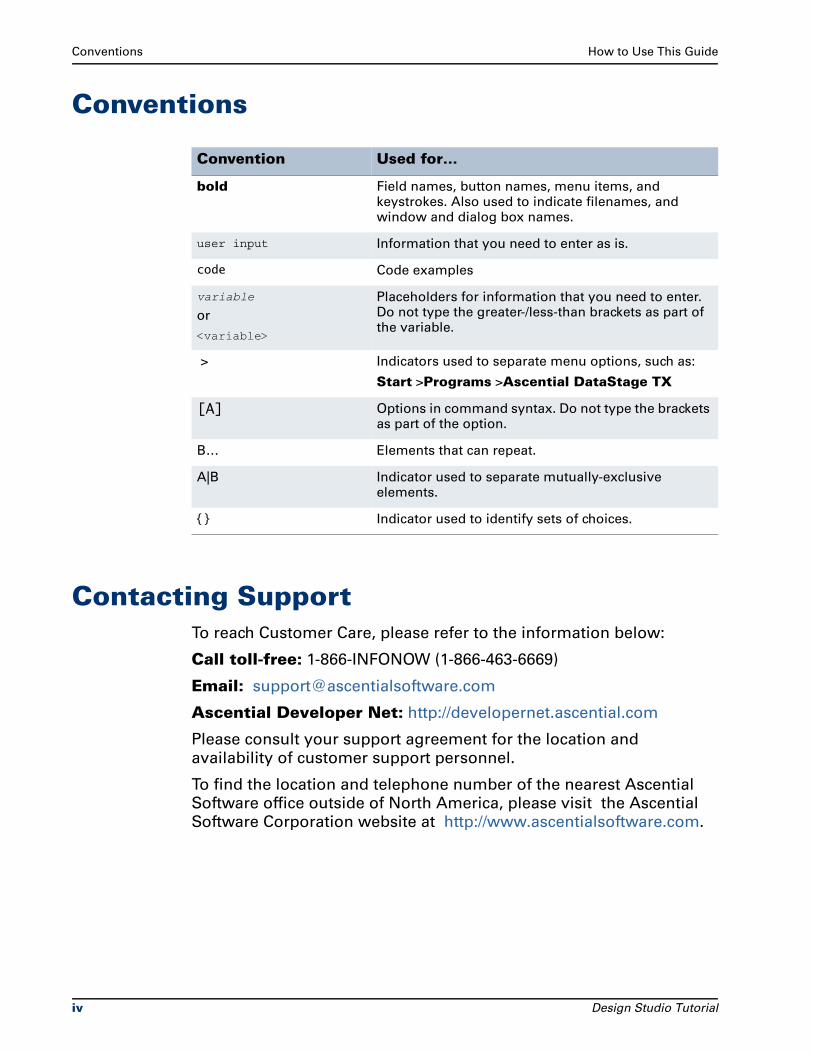
Conventions
Contacting SupportTo reach Customer Care, please refer to the information below:
Call toll-free: 1-866-INFONOW (1-866-463-6669)
Email: [email protected]
Ascential Developer Net: http://developernet.ascential.com
Please consult your support agreement for the location and
availability of customer support personnel.
To find the location and telephone number of the nearest Ascential
Software office outside of North America, please visit the Ascential
Software Corporation website at http://www.ascentialsoftware.com.
Convention Used for…
bold Field names, button names, menu items, and keystrokes. Also used to indicate filenames, and window and dialog box names.
user input Information that you need to enter as is.
code Code examples
variable
or
<variable>
Placeholders for information that you need to enter. Do not type the greater-/less-than brackets as part of the variable.
> Indicators used to separate menu options, such as:
Start >Programs >Ascential DataStage TX
[A] Options in command syntax. Do not type the brackets as part of the option.
B… Elements that can repeat.
A|B Indicator used to separate mutually-exclusive elements.
{ } Indicator used to identify sets of choices.
iv Design Studio Tutorial
Contents
How to Use This GuideRelated Documentation . . . . . . . . . . . . . . . . . . . . . . . . . . . . . . . . . . . . . . . . . . . . . iii
Conventions . . . . . . . . . . . . . . . . . . . . . . . . . . . . . . . . . . . . . . . . . . . . . . . . . . . . . . . iv
Contacting Support . . . . . . . . . . . . . . . . . . . . . . . . . . . . . . . . . . . . . . . . . . . . . . . . . iv
IntroductionDesign Studio Overview . . . . . . . . . . . . . . . . . . . . . . . . . . . . . . . . . . . . . . . . . . . xvii
Tutorial Objectives . . . . . . . . . . . . . . . . . . . . . . . . . . . . . . . . . . . . . . . . . . . . . . . xviii
Help Overview . . . . . . . . . . . . . . . . . . . . . . . . . . . . . . . . . . . . . . . . . . . . . . . . . . . . xix
Menu Commands and Tools . . . . . . . . . . . . . . . . . . . . . . . . . . . . . . . . . . . . . . . . xix
Installation . . . . . . . . . . . . . . . . . . . . . . . . . . . . . . . . . . . . . . . . . . . . . . . . . . . . . . . xx
Your Working Folders . . . . . . . . . . . . . . . . . . . . . . . . . . . . . . . . . . . . . . . . . . . . . . xx
Design Studio Tutorial Exercises . . . . . . . . . . . . . . . . . . . . . . . . . . . . . . . . . xxi
Unzipping the Ch01.exe File . . . . . . . . . . . . . . . . . . . . . . . . . . . . . . . . . . . . . xxi
Design Studio Tutorial Solutions . . . . . . . . . . . . . . . . . . . . . . . . . . . . . . . . . xxii
Chapter 1Mapping Basics
Objectives . . . . . . . . . . . . . . . . . . . . . . . . . . . . . . . . . . . . . . . . . . . . . . . . . . . . . . . 1-1
Files Used in This Chapter. . . . . . . . . . . . . . . . . . . . . . . . . . . . . . . . . . . . . . . . . . 1-2
Files Provided for Chapter 1 . . . . . . . . . . . . . . . . . . . . . . . . . . . . . . . . . . . . . 1-2
Files Created for Chapter 1 . . . . . . . . . . . . . . . . . . . . . . . . . . . . . . . . . . . . . . 1-2
Scenario . . . . . . . . . . . . . . . . . . . . . . . . . . . . . . . . . . . . . . . . . . . . . . . . . . . . . . . . 1-3
Contact Record . . . . . . . . . . . . . . . . . . . . . . . . . . . . . . . . . . . . . . . . . . . . . . . . 1-3
Label Record . . . . . . . . . . . . . . . . . . . . . . . . . . . . . . . . . . . . . . . . . . . . . . . . . . 1-6
Starting the Map Designer . . . . . . . . . . . . . . . . . . . . . . . . . . . . . . . . . . . . . . . . . 1-8
Exploring the ContactToLabel Map . . . . . . . . . . . . . . . . . . . . . . . . . . . . . . . 1-9
Design Studio Tutorial v
Contents
Link Between the Map Designer and Type Designer . . . . . . . . . . . . . . . . 1-14
Viewing Components in the ContactToLabel Map . . . . . . . . . . . . . . . . . . . . . 1-15
ContactToLabel Map Cards . . . . . . . . . . . . . . . . . . . . . . . . . . . . . . . . . . . . . 1-17
Map Rules. . . . . . . . . . . . . . . . . . . . . . . . . . . . . . . . . . . . . . . . . . . . . . . . . . . . . . 1-19
Data Object Names in Map Rules . . . . . . . . . . . . . . . . . . . . . . . . . . . . . . . . 1-20
Viewing the Map Rules on the ContactToLabel Map . . . . . . . . . . . . . . . . 1-20
Using the Navigator. . . . . . . . . . . . . . . . . . . . . . . . . . . . . . . . . . . . . . . . . . . 1-21
Building the ContactToLabel Map . . . . . . . . . . . . . . . . . . . . . . . . . . . . . . . . . . 1-22
Results. . . . . . . . . . . . . . . . . . . . . . . . . . . . . . . . . . . . . . . . . . . . . . . . . . . . . . 1-23
Running the ContactToLabel Map . . . . . . . . . . . . . . . . . . . . . . . . . . . . . . . . . . 1-24
Results. . . . . . . . . . . . . . . . . . . . . . . . . . . . . . . . . . . . . . . . . . . . . . . . . . . . . . 1-24
Viewing the ContactToLabel Map Run Results . . . . . . . . . . . . . . . . . . . . . 1-25
Closing Multiple Run Results Windows . . . . . . . . . . . . . . . . . . . . . . . . . . . 1-26
Summary . . . . . . . . . . . . . . . . . . . . . . . . . . . . . . . . . . . . . . . . . . . . . . . . . . . . . . 1-27
ContactToLabel Map Source. . . . . . . . . . . . . . . . . . . . . . . . . . . . . . . . . . . . 1-27
ContactToLabel Map Target . . . . . . . . . . . . . . . . . . . . . . . . . . . . . . . . . . . . 1-28
Chapter 2Modifying the Contact Type Tree
Objectives. . . . . . . . . . . . . . . . . . . . . . . . . . . . . . . . . . . . . . . . . . . . . . . . . . . . . . . 2-1
Files Used in This Chapter . . . . . . . . . . . . . . . . . . . . . . . . . . . . . . . . . . . . . . . . . 2-2
Files Provided for Chapter 2 . . . . . . . . . . . . . . . . . . . . . . . . . . . . . . . . . . . . . 2-2
Files You Create or Modify for Chapter 2. . . . . . . . . . . . . . . . . . . . . . . . . . . 2-2
Scenario . . . . . . . . . . . . . . . . . . . . . . . . . . . . . . . . . . . . . . . . . . . . . . . . . . . . . . . . 2-3
FullContact Record. . . . . . . . . . . . . . . . . . . . . . . . . . . . . . . . . . . . . . . . . . . . . 2-3
Label Output . . . . . . . . . . . . . . . . . . . . . . . . . . . . . . . . . . . . . . . . . . . . . . . . . . 2-4
Starting the Type Designer . . . . . . . . . . . . . . . . . . . . . . . . . . . . . . . . . . . . . . . . . 2-4
Exploring the Contact Type Tree . . . . . . . . . . . . . . . . . . . . . . . . . . . . . . . . . 2-5
Type Properties . . . . . . . . . . . . . . . . . . . . . . . . . . . . . . . . . . . . . . . . . . . . . . . . . . 2-7
Viewing Type Properties . . . . . . . . . . . . . . . . . . . . . . . . . . . . . . . . . . . . . . . . . . . 2-7
Properties of the Contact Group Type . . . . . . . . . . . . . . . . . . . . . . . . . . . . . . . . 2-8
Components of Contact. . . . . . . . . . . . . . . . . . . . . . . . . . . . . . . . . . . . . . . . . . . . 2-9
Classification Hierarchy. . . . . . . . . . . . . . . . . . . . . . . . . . . . . . . . . . . . . . . . . . . 2-10
Adding a New Type . . . . . . . . . . . . . . . . . . . . . . . . . . . . . . . . . . . . . . . . . . . 2-10
Adding Components to Group Types . . . . . . . . . . . . . . . . . . . . . . . . . . . . . . . 2-14
Component Ranges . . . . . . . . . . . . . . . . . . . . . . . . . . . . . . . . . . . . . . . . . . . 2-16
Saving the Contact.mtt Type Tree . . . . . . . . . . . . . . . . . . . . . . . . . . . . . . . 2-17
Summary . . . . . . . . . . . . . . . . . . . . . . . . . . . . . . . . . . . . . . . . . . . . . . . . . . . . . . 2-18
vi Design Studio Tutorial
Contents
Chapter 3Modifying the Mail.mss Map Source File
Objectives . . . . . . . . . . . . . . . . . . . . . . . . . . . . . . . . . . . . . . . . . . . . . . . . . . . . . . . 3-1
Files Used in This Chapter. . . . . . . . . . . . . . . . . . . . . . . . . . . . . . . . . . . . . . . . . . 3-2
Files Provided for Chapter 3 . . . . . . . . . . . . . . . . . . . . . . . . . . . . . . . . . . . . . 3-2
Files You Create or Modify for Chapter 3 . . . . . . . . . . . . . . . . . . . . . . . . . . . 3-2
Scenario . . . . . . . . . . . . . . . . . . . . . . . . . . . . . . . . . . . . . . . . . . . . . . . . . . . . . . . . 3-3
Copying an Input Card. . . . . . . . . . . . . . . . . . . . . . . . . . . . . . . . . . . . . . . . . . . . . 3-4
Modifying the ContactToFullLabel Map. . . . . . . . . . . . . . . . . . . . . . . . . . . . . . . 3-5
Creating the Label Output Card. . . . . . . . . . . . . . . . . . . . . . . . . . . . . . . . . . . 3-6
Editing the ContactFile Input Card . . . . . . . . . . . . . . . . . . . . . . . . . . . . . . . 3-10
Creating the Map Rule for Label(s) . . . . . . . . . . . . . . . . . . . . . . . . . . . . . . . 3-11
Executable and Functional Maps . . . . . . . . . . . . . . . . . . . . . . . . . . . . . . . . . . . 3-11
Functional Maps . . . . . . . . . . . . . . . . . . . . . . . . . . . . . . . . . . . . . . . . . . . . . . 3-12
General Functional Map Guidelines . . . . . . . . . . . . . . . . . . . . . . . . . . . . . . 3-13
Label Map Rule . . . . . . . . . . . . . . . . . . . . . . . . . . . . . . . . . . . . . . . . . . . . 3-16
Functional Map Wizard . . . . . . . . . . . . . . . . . . . . . . . . . . . . . . . . . . . . . . . . 3-16
Entering Map Rules . . . . . . . . . . . . . . . . . . . . . . . . . . . . . . . . . . . . . . . . . . . . . . 3-20
Mapping to the Company Field. . . . . . . . . . . . . . . . . . . . . . . . . . . . . . . . . . 3-20
Data Object Name Reminder. . . . . . . . . . . . . . . . . . . . . . . . . . . . . . . . . . . . 3-22
Viewing Map Rules. . . . . . . . . . . . . . . . . . . . . . . . . . . . . . . . . . . . . . . . . . . . 3-22
Sizing the Rule Column and Output Column . . . . . . . . . . . . . . . . . . . . . . . 3-22
Mapping to the Street Field . . . . . . . . . . . . . . . . . . . . . . . . . . . . . . . . . . . . . 3-23
Mapping to CityStateZip Field. . . . . . . . . . . . . . . . . . . . . . . . . . . . . . . . . . . 3-23
Mapping to the FullName Field. . . . . . . . . . . . . . . . . . . . . . . . . . . . . . . . . . 3-25
Functions Used in Map Rule . . . . . . . . . . . . . . . . . . . . . . . . . . . . . . . . . 3-25
PRESENT Function . . . . . . . . . . . . . . . . . . . . . . . . . . . . . . . . . . . . . . . . . 3-25
IF Function . . . . . . . . . . . . . . . . . . . . . . . . . . . . . . . . . . . . . . . . . . . . . . . . 3-25
Mapping the FullName Field . . . . . . . . . . . . . . . . . . . . . . . . . . . . . . . . . . . . 3-26
Mapping the Second Argument of the IF function . . . . . . . . . . . . . . . 3-28
Mapping the Third Argument of the IF function . . . . . . . . . . . . . . . . . 3-29
Saving the Mail.mms Map Source File . . . . . . . . . . . . . . . . . . . . . . . . . . . . . . 3-30
Building the ContactToFullLabel Map . . . . . . . . . . . . . . . . . . . . . . . . . . . . . . . 3-31
Running the ContactToFullLabel Map . . . . . . . . . . . . . . . . . . . . . . . . . . . . . . . 3-31
Results . . . . . . . . . . . . . . . . . . . . . . . . . . . . . . . . . . . . . . . . . . . . . . . . . . . . . . 3-32
Viewing the ContactToFullLabel Map Run Results . . . . . . . . . . . . . . . . . . 3-32
Summary . . . . . . . . . . . . . . . . . . . . . . . . . . . . . . . . . . . . . . . . . . . . . . . . . . . . . . 3-34
Design Studio Tutorial vii
Contents
Chapter 4Using the UNIQUE Function
Objectives. . . . . . . . . . . . . . . . . . . . . . . . . . . . . . . . . . . . . . . . . . . . . . . . . . . . . . . 4-1
Files Used in This Chapter . . . . . . . . . . . . . . . . . . . . . . . . . . . . . . . . . . . . . . . . . 4-1
Files Provided for Chapter 4 . . . . . . . . . . . . . . . . . . . . . . . . . . . . . . . . . . . . . 4-2
Files You Create or Modify for Chapter 4. . . . . . . . . . . . . . . . . . . . . . . . . . . 4-2
Scenario . . . . . . . . . . . . . . . . . . . . . . . . . . . . . . . . . . . . . . . . . . . . . . . . . . . . . . . . 4-3
Copying an Input Card to a New Map . . . . . . . . . . . . . . . . . . . . . . . . . . . . . . . . 4-3
Copying an Input Card to an Output Card . . . . . . . . . . . . . . . . . . . . . . . . . . . . . 4-4
Editing a Card. . . . . . . . . . . . . . . . . . . . . . . . . . . . . . . . . . . . . . . . . . . . . . . . . . . . 4-6
Summary . . . . . . . . . . . . . . . . . . . . . . . . . . . . . . . . . . . . . . . . . . . . . . . . . . . . . . . 4-9
Chapter 5Using the EXTRACT Function
Objectives. . . . . . . . . . . . . . . . . . . . . . . . . . . . . . . . . . . . . . . . . . . . . . . . . . . . . . . 5-1
Files Used in This Chapter . . . . . . . . . . . . . . . . . . . . . . . . . . . . . . . . . . . . . . . . . 5-1
Files Provided for Chapter 5 . . . . . . . . . . . . . . . . . . . . . . . . . . . . . . . . . . . . . 5-2
Files You Create or Modify for Chapter 5. . . . . . . . . . . . . . . . . . . . . . . . . . . 5-2
Scenario . . . . . . . . . . . . . . . . . . . . . . . . . . . . . . . . . . . . . . . . . . . . . . . . . . . . . . . . 5-3
Extracting Contacts for a Specific State. . . . . . . . . . . . . . . . . . . . . . . . . . . . . . . 5-3
Copying the ContactToFullLabel Map . . . . . . . . . . . . . . . . . . . . . . . . . . . . . . . . 5-3
Defining a New Input File . . . . . . . . . . . . . . . . . . . . . . . . . . . . . . . . . . . . . . . 5-4
Defining a New Output File . . . . . . . . . . . . . . . . . . . . . . . . . . . . . . . . . . . . . . 5-5
Entering a Map Rule to Extract Specific Records . . . . . . . . . . . . . . . . . . . . . . . 5-6
Card Naming Conventions . . . . . . . . . . . . . . . . . . . . . . . . . . . . . . . . . . . . . . 5-6
Summary . . . . . . . . . . . . . . . . . . . . . . . . . . . . . . . . . . . . . . . . . . . . . . . . . . . . . . . 5-9
Chapter 6Using the OR Function With a Lookup File
Objectives. . . . . . . . . . . . . . . . . . . . . . . . . . . . . . . . . . . . . . . . . . . . . . . . . . . . . . . 6-1
Files Used in This Chapter . . . . . . . . . . . . . . . . . . . . . . . . . . . . . . . . . . . . . . . . . 6-2
Files Provided for Chapter 6 . . . . . . . . . . . . . . . . . . . . . . . . . . . . . . . . . . . . . 6-2
Files You Create or Modify for Chapter 6. . . . . . . . . . . . . . . . . . . . . . . . . . . 6-2
Scenario . . . . . . . . . . . . . . . . . . . . . . . . . . . . . . . . . . . . . . . . . . . . . . . . . . . . . . . . 6-3
Type Designer and Map Designer Tasks . . . . . . . . . . . . . . . . . . . . . . . . . . . 6-3
Using the Type Designer. . . . . . . . . . . . . . . . . . . . . . . . . . . . . . . . . . . . . . . . . . . 6-4
Using Type Inheritance . . . . . . . . . . . . . . . . . . . . . . . . . . . . . . . . . . . . . . . . . 6-4
Creating the Preferred Type Tree . . . . . . . . . . . . . . . . . . . . . . . . . . . . . . . . . . . . 6-5
viii Design Studio Tutorial
Contents
Naming the Preferred Type Tree. . . . . . . . . . . . . . . . . . . . . . . . . . . . . . . . . . 6-6
Creating the PreferredFile Group Type. . . . . . . . . . . . . . . . . . . . . . . . . . . . . 6-8
Creating the Field Item Types . . . . . . . . . . . . . . . . . . . . . . . . . . . . . . . . . . . . 6-8
Defining the PurchaseDate Item Properties . . . . . . . . . . . . . . . . . . . . . . . . . 6-9
Defining the Customer Group Type . . . . . . . . . . . . . . . . . . . . . . . . . . . . . . 6-10
Defining the PreferredFile Group Type. . . . . . . . . . . . . . . . . . . . . . . . . . . . 6-13
Saving and Analyzing the Preferred Type Tree . . . . . . . . . . . . . . . . . . . . . 6-16
MakePreferredData Map . . . . . . . . . . . . . . . . . . . . . . . . . . . . . . . . . . . . . . . . . . 6-16
Creating the PreferredFile Output Card . . . . . . . . . . . . . . . . . . . . . . . . . . . 6-17
Creating Multiple Occurrences of Customer . . . . . . . . . . . . . . . . . . . . . . . 6-17
Creating the Map Rules . . . . . . . . . . . . . . . . . . . . . . . . . . . . . . . . . . . . . . . . 6-18
Using the TODATETIME Function. . . . . . . . . . . . . . . . . . . . . . . . . . . . . . . . 6-19
Generating Customer[2] and Customer[3] Output . . . . . . . . . . . . . . . . . . 6-20
Building and Running the MakePreferredData Map . . . . . . . . . . . . . . . . . 6-20
Extracting Contacts that are Preferred . . . . . . . . . . . . . . . . . . . . . . . . . . . . . . . 6-21
Summary . . . . . . . . . . . . . . . . . . . . . . . . . . . . . . . . . . . . . . . . . . . . . . . . . . . . . . 6-22
Chapter 7Using Cross-Referenced Data
Objectives . . . . . . . . . . . . . . . . . . . . . . . . . . . . . . . . . . . . . . . . . . . . . . . . . . . . . . . 7-1
Files Used in This Chapter. . . . . . . . . . . . . . . . . . . . . . . . . . . . . . . . . . . . . . . . . . 7-2
Files Provided for Chapter 7 . . . . . . . . . . . . . . . . . . . . . . . . . . . . . . . . . . . . . 7-2
Files You Create or Modify for Chapter 7 . . . . . . . . . . . . . . . . . . . . . . . . . . . 7-2
Scenario . . . . . . . . . . . . . . . . . . . . . . . . . . . . . . . . . . . . . . . . . . . . . . . . . . . . . . . . 7-4
Modifying the Customer.mtt Type Tree. . . . . . . . . . . . . . . . . . . . . . . . . . . . . . . 7-4
Field Item Types . . . . . . . . . . . . . . . . . . . . . . . . . . . . . . . . . . . . . . . . . . . . 7-5
Region Data. . . . . . . . . . . . . . . . . . . . . . . . . . . . . . . . . . . . . . . . . . . . . . . . . . . 7-5
Record Group Type Represents Region Records . . . . . . . . . . . . . . . . . . . . 7-6
Properties of Record . . . . . . . . . . . . . . . . . . . . . . . . . . . . . . . . . . . . . . . . . 7-6
Components of Record. . . . . . . . . . . . . . . . . . . . . . . . . . . . . . . . . . . . . . . 7-7
RegionRecordsFile Group Type Represents the File . . . . . . . . . . . . . . . . . . 7-8
Properties of RegionRecordsFile . . . . . . . . . . . . . . . . . . . . . . . . . . . . . . . 7-8
Component of RegionRecordsFile. . . . . . . . . . . . . . . . . . . . . . . . . . . . . . 7-8
Save the Customer.mtt Type Tree . . . . . . . . . . . . . . . . . . . . . . . . . . . . . . . . 7-9
Output Types . . . . . . . . . . . . . . . . . . . . . . . . . . . . . . . . . . . . . . . . . . . . . . . . . . . . 7-9
Using the Map Designer to Generate Region Reports . . . . . . . . . . . . . . . . . . 7-10
Creating the CreateRegionFile Map . . . . . . . . . . . . . . . . . . . . . . . . . . . . . . 7-10
Creating the RegionReport Map . . . . . . . . . . . . . . . . . . . . . . . . . . . . . . . . . . . . 7-12
Design Studio Tutorial ix
Contents
Creating the F_MakeSalesRecord Functional Map . . . . . . . . . . . . . . . . . . . . . 7-12
Using the LOOKUP Function. . . . . . . . . . . . . . . . . . . . . . . . . . . . . . . . . . . . 7-12
Using the Functional Map Wizard . . . . . . . . . . . . . . . . . . . . . . . . . . . . . . . 7-13
Modify the F_MakeSalesRecord Functional Map . . . . . . . . . . . . . . . . . . . 7-14
Generating the Output of SalesRecord . . . . . . . . . . . . . . . . . . . . . . . . . . . . . . 7-15
Using the SORTDOWN Function . . . . . . . . . . . . . . . . . . . . . . . . . . . . . . . . . . . 7-15
Creating the SortRegion_Descending Map . . . . . . . . . . . . . . . . . . . . . . . . . . . 7-15
Optional Exercise. . . . . . . . . . . . . . . . . . . . . . . . . . . . . . . . . . . . . . . . . . . . . . . . 7-17
Using the SEARCHUP Function . . . . . . . . . . . . . . . . . . . . . . . . . . . . . . . . . . . . 7-17
Creating the RegionReport_SEARCHUP Map . . . . . . . . . . . . . . . . . . . . . . . . . 7-18
Optional Exercise . . . . . . . . . . . . . . . . . . . . . . . . . . . . . . . . . . . . . . . . . . . . . 7-19
Chapter 8Using the CHOOSE Function
Objectives. . . . . . . . . . . . . . . . . . . . . . . . . . . . . . . . . . . . . . . . . . . . . . . . . . . . . . . 8-1
Files Used in This Chapter . . . . . . . . . . . . . . . . . . . . . . . . . . . . . . . . . . . . . . . . . 8-1
Files Provided for Chapter 8 . . . . . . . . . . . . . . . . . . . . . . . . . . . . . . . . . . . . . 8-1
Files You Create or Modify for Chapter 8. . . . . . . . . . . . . . . . . . . . . . . . . . . 8-2
Scenario . . . . . . . . . . . . . . . . . . . . . . . . . . . . . . . . . . . . . . . . . . . . . . . . . . . . . . . . 8-3
Generating the Congratulations Message File . . . . . . . . . . . . . . . . . . . . . . . . . 8-3
Raffle.mtt Type Tree . . . . . . . . . . . . . . . . . . . . . . . . . . . . . . . . . . . . . . . . . . . . . . 8-4
PrizeRecord Group Type . . . . . . . . . . . . . . . . . . . . . . . . . . . . . . . . . . . . . . . . 8-4
PrizeFile Group Type . . . . . . . . . . . . . . . . . . . . . . . . . . . . . . . . . . . . . . . . . . . 8-5
WinnerFile Group Type . . . . . . . . . . . . . . . . . . . . . . . . . . . . . . . . . . . . . . . . . 8-5
CongratulationsRecord Group Type. . . . . . . . . . . . . . . . . . . . . . . . . . . . . . . 8-6
CongratulationsFile Group Type. . . . . . . . . . . . . . . . . . . . . . . . . . . . . . . . . . 8-7
Raffle Map . . . . . . . . . . . . . . . . . . . . . . . . . . . . . . . . . . . . . . . . . . . . . . . . . . . . . . 8-7
Summary . . . . . . . . . . . . . . . . . . . . . . . . . . . . . . . . . . . . . . . . . . . . . . . . . . . . . . . 8-9
Chapter 9Data Breaks By Object Count
Objectives. . . . . . . . . . . . . . . . . . . . . . . . . . . . . . . . . . . . . . . . . . . . . . . . . . . . . . . 9-1
Files Used in This Chapter . . . . . . . . . . . . . . . . . . . . . . . . . . . . . . . . . . . . . . . . . 9-2
Files Provided for Chapter 9 . . . . . . . . . . . . . . . . . . . . . . . . . . . . . . . . . . . . . 9-2
Files You Create or Modify for Chapter 9. . . . . . . . . . . . . . . . . . . . . . . . . . . 9-2
Scenario – Counting Objects. . . . . . . . . . . . . . . . . . . . . . . . . . . . . . . . . . . . . . . . 9-3
Merging the Contact Group Type. . . . . . . . . . . . . . . . . . . . . . . . . . . . . . . . . . . . 9-4
Adding a Component Rule . . . . . . . . . . . . . . . . . . . . . . . . . . . . . . . . . . . . . . 9-8
x Design Studio Tutorial
Contents
Using the Map Designer . . . . . . . . . . . . . . . . . . . . . . . . . . . . . . . . . . . . . . . . . . 9-12
Summary . . . . . . . . . . . . . . . . . . . . . . . . . . . . . . . . . . . . . . . . . . . . . . . . . . . . . . 9-15
Chapter 10Data Breaks By Value
Objectives . . . . . . . . . . . . . . . . . . . . . . . . . . . . . . . . . . . . . . . . . . . . . . . . . . . . . . 10-1
Files Used in This Chapter. . . . . . . . . . . . . . . . . . . . . . . . . . . . . . . . . . . . . . . . . 10-2
Files Provided for Chapter 10 . . . . . . . . . . . . . . . . . . . . . . . . . . . . . . . . . . . 10-2
Files You Create or Modify for Chapter 10 . . . . . . . . . . . . . . . . . . . . . . . . . 10-2
Scenario - Data Value Changes. . . . . . . . . . . . . . . . . . . . . . . . . . . . . . . . . . . . . 10-3
Control.mtt Type Tree . . . . . . . . . . . . . . . . . . . . . . . . . . . . . . . . . . . . . . . . . . . . 10-3
Adding a Component Rule for Distinguishability . . . . . . . . . . . . . . . . . . . 10-4
Using Shorthand Notation in a Component Rule . . . . . . . . . . . . . . . . . . . 10-6
Data Handling . . . . . . . . . . . . . . . . . . . . . . . . . . . . . . . . . . . . . . . . . . . . . . . . 10-6
Creating the MakeCountFile Map . . . . . . . . . . . . . . . . . . . . . . . . . . . . . . . . . . . 10-7
Summary . . . . . . . . . . . . . . . . . . . . . . . . . . . . . . . . . . . . . . . . . . . . . . . . . . . . . . 10-8
Chapter 11Partitioning Types To Simplify Map Rules
Objectives . . . . . . . . . . . . . . . . . . . . . . . . . . . . . . . . . . . . . . . . . . . . . . . . . . . . . . 11-1
Files Used in This Chapter. . . . . . . . . . . . . . . . . . . . . . . . . . . . . . . . . . . . . . . . . 11-2
Files Provided for Chapter 11 . . . . . . . . . . . . . . . . . . . . . . . . . . . . . . . . . . . 11-2
Files You Create or Modify for Chapter 11 . . . . . . . . . . . . . . . . . . . . . . . . . 11-2
Scenario . . . . . . . . . . . . . . . . . . . . . . . . . . . . . . . . . . . . . . . . . . . . . . . . . . . . . . . 11-3
Partitioned Type Names . . . . . . . . . . . . . . . . . . . . . . . . . . . . . . . . . . . . . . . 11-4
Deliver.mtt Type tree . . . . . . . . . . . . . . . . . . . . . . . . . . . . . . . . . . . . . . . . . . . . . 11-5
Assigning the Identifier Attribute . . . . . . . . . . . . . . . . . . . . . . . . . . . . . . . . 11-6
Entering Component Rules . . . . . . . . . . . . . . . . . . . . . . . . . . . . . . . . . . . . . 11-7
Viewing Component Numbers . . . . . . . . . . . . . . . . . . . . . . . . . . . . . . . . . . . . . 11-9
Deliver Map Source File . . . . . . . . . . . . . . . . . . . . . . . . . . . . . . . . . . . . . . . . . 11-11
OrdersByDept Executable Map . . . . . . . . . . . . . . . . . . . . . . . . . . . . . . . . . 11-12
Generating the Acct.txt File . . . . . . . . . . . . . . . . . . . . . . . . . . . . . . . . . 11-12
Generating the Order.txt File . . . . . . . . . . . . . . . . . . . . . . . . . . . . . . . . 11-13
ActivityReport Executable Map . . . . . . . . . . . . . . . . . . . . . . . . . . . . . . . . . 11-14
Generating the Report.txt File . . . . . . . . . . . . . . . . . . . . . . . . . . . . . . . 11-15
Summary . . . . . . . . . . . . . . . . . . . . . . . . . . . . . . . . . . . . . . . . . . . . . . . . . . . . . 11-17
Design Studio Tutorial xi
Contents
Chapter 12Mapping Optional Inputs
Objectives. . . . . . . . . . . . . . . . . . . . . . . . . . . . . . . . . . . . . . . . . . . . . . . . . . . . . . 12-1
Files Used in This Chapter . . . . . . . . . . . . . . . . . . . . . . . . . . . . . . . . . . . . . . . . 12-1
Files Provided for Chapter 12 . . . . . . . . . . . . . . . . . . . . . . . . . . . . . . . . . . . 12-1
Files You Create or Modify for Chapter 12. . . . . . . . . . . . . . . . . . . . . . . . . 12-2
Scenario . . . . . . . . . . . . . . . . . . . . . . . . . . . . . . . . . . . . . . . . . . . . . . . . . . . . . . . 12-2
Input Data . . . . . . . . . . . . . . . . . . . . . . . . . . . . . . . . . . . . . . . . . . . . . . . . . . . . . . 12-3
States.mtt Type Tree . . . . . . . . . . . . . . . . . . . . . . . . . . . . . . . . . . . . . . . . . . . . . 12-3
Component Ranges . . . . . . . . . . . . . . . . . . . . . . . . . . . . . . . . . . . . . . . . . . . . . . 12-4
Using the Map Designer . . . . . . . . . . . . . . . . . . . . . . . . . . . . . . . . . . . . . . . . . . 12-8
Summary . . . . . . . . . . . . . . . . . . . . . . . . . . . . . . . . . . . . . . . . . . . . . . . . . . . . . 12-10
Chapter 13Mapping Multiple Files to One File
Objectives. . . . . . . . . . . . . . . . . . . . . . . . . . . . . . . . . . . . . . . . . . . . . . . . . . . . . . 13-1
Files Used in This Chapter . . . . . . . . . . . . . . . . . . . . . . . . . . . . . . . . . . . . . . . . 13-1
Files Provided for Chapter 13 . . . . . . . . . . . . . . . . . . . . . . . . . . . . . . . . . . . 13-1
Files You Create or Modify for Chapter 13. . . . . . . . . . . . . . . . . . . . . . . . . 13-2
Scenario . . . . . . . . . . . . . . . . . . . . . . . . . . . . . . . . . . . . . . . . . . . . . . . . . . . . . . . 13-3
Using Ellipses. . . . . . . . . . . . . . . . . . . . . . . . . . . . . . . . . . . . . . . . . . . . . . . . . . . 13-3
TwoFiles.mtt Type Tree. . . . . . . . . . . . . . . . . . . . . . . . . . . . . . . . . . . . . . . . . . . 13-5
Input Detail Records. . . . . . . . . . . . . . . . . . . . . . . . . . . . . . . . . . . . . . . . . . . 13-5
Input Header Records . . . . . . . . . . . . . . . . . . . . . . . . . . . . . . . . . . . . . . . . . 13-6
Output PO . . . . . . . . . . . . . . . . . . . . . . . . . . . . . . . . . . . . . . . . . . . . . . . . . . . 13-7
Using the Map Designer . . . . . . . . . . . . . . . . . . . . . . . . . . . . . . . . . . . . . . . . . . 13-7
CreatePO Input . . . . . . . . . . . . . . . . . . . . . . . . . . . . . . . . . . . . . . . . . . . . . . . 13-7
Generating the CreatePO Output . . . . . . . . . . . . . . . . . . . . . . . . . . . . . . . . 13-8
F_MakePO Functional Map . . . . . . . . . . . . . . . . . . . . . . . . . . . . . . . . . . . . . 13-9
F_MakeDetail Functional Map. . . . . . . . . . . . . . . . . . . . . . . . . . . . . . . . . . 13-10
CreatePO Executable Map. . . . . . . . . . . . . . . . . . . . . . . . . . . . . . . . . . . . . . . . 13-10
Generating the PO.txt Output File . . . . . . . . . . . . . . . . . . . . . . . . . . . . . . . . . 13-11
Summary . . . . . . . . . . . . . . . . . . . . . . . . . . . . . . . . . . . . . . . . . . . . . . . . . . . . . 13-11
Chapter 14Detail Records Not Sorted by PO
Objectives. . . . . . . . . . . . . . . . . . . . . . . . . . . . . . . . . . . . . . . . . . . . . . . . . . . . . . 14-1
Files Used in This Chapter . . . . . . . . . . . . . . . . . . . . . . . . . . . . . . . . . . . . . . . . 14-1
xii Design Studio Tutorial
Contents
Files Provided for Chapter 14 . . . . . . . . . . . . . . . . . . . . . . . . . . . . . . . . . . . 14-1
Files You Create or Modify for Chapter 14 . . . . . . . . . . . . . . . . . . . . . . . . . 14-2
Scenario . . . . . . . . . . . . . . . . . . . . . . . . . . . . . . . . . . . . . . . . . . . . . . . . . . . . . . . 14-3
RandomDetails.mtt Type Tree . . . . . . . . . . . . . . . . . . . . . . . . . . . . . . . . . . . . . 14-4
Using the Map Designer . . . . . . . . . . . . . . . . . . . . . . . . . . . . . . . . . . . . . . . . . . 14-4
RandomDetails Input . . . . . . . . . . . . . . . . . . . . . . . . . . . . . . . . . . . . . . . . . . 14-4
Generating the RandomDetails Output . . . . . . . . . . . . . . . . . . . . . . . . . . . 14-5
F_MakePO2 Functional Map . . . . . . . . . . . . . . . . . . . . . . . . . . . . . . . . . . . . 14-5
F_MakeDetail2 Functional Map . . . . . . . . . . . . . . . . . . . . . . . . . . . . . . . . . . 14-6
RandomDetails Executable Map. . . . . . . . . . . . . . . . . . . . . . . . . . . . . . . . . . . . 14-6
Generating the PO2.txt Output File . . . . . . . . . . . . . . . . . . . . . . . . . . . . . . . . . 14-7
Viewing Run Results . . . . . . . . . . . . . . . . . . . . . . . . . . . . . . . . . . . . . . . . . . . . . 14-7
Summary . . . . . . . . . . . . . . . . . . . . . . . . . . . . . . . . . . . . . . . . . . . . . . . . . . . . . . 14-8
Chapter 15Creating a Trace File
Objectives . . . . . . . . . . . . . . . . . . . . . . . . . . . . . . . . . . . . . . . . . . . . . . . . . . . . . . 15-1
Files Used in This Chapter. . . . . . . . . . . . . . . . . . . . . . . . . . . . . . . . . . . . . . . . . 15-1
Files Provided for Chapter 15 . . . . . . . . . . . . . . . . . . . . . . . . . . . . . . . . . . . 15-2
Files You Create or Modify for Chapter 15 . . . . . . . . . . . . . . . . . . . . . . . . . 15-2
Scenario . . . . . . . . . . . . . . . . . . . . . . . . . . . . . . . . . . . . . . . . . . . . . . . . . . . . . . . 15-3
Trace File. . . . . . . . . . . . . . . . . . . . . . . . . . . . . . . . . . . . . . . . . . . . . . . . . . . . . . . 15-3
Creating a Trace File. . . . . . . . . . . . . . . . . . . . . . . . . . . . . . . . . . . . . . . . . . . 15-4
Changing MapTrace Settings . . . . . . . . . . . . . . . . . . . . . . . . . . . . . . . . . . . 15-4
Viewing the Trace File . . . . . . . . . . . . . . . . . . . . . . . . . . . . . . . . . . . . . . . . . . . . 15-5
Customer# Type Properties . . . . . . . . . . . . . . . . . . . . . . . . . . . . . . . . . . . . . 15-5
Floating the Trace File in the Main Window . . . . . . . . . . . . . . . . . . . . . . . . . . 15-6
Data Validation . . . . . . . . . . . . . . . . . . . . . . . . . . . . . . . . . . . . . . . . . . . . . . . . . . 15-6
Item Type Validation . . . . . . . . . . . . . . . . . . . . . . . . . . . . . . . . . . . . . . . . . . 15-6
Group Validation . . . . . . . . . . . . . . . . . . . . . . . . . . . . . . . . . . . . . . . . . . . . . 15-8
Card Object Validation . . . . . . . . . . . . . . . . . . . . . . . . . . . . . . . . . . . . . . . . . 15-8
Final Trace Message. . . . . . . . . . . . . . . . . . . . . . . . . . . . . . . . . . . . . . . . . . . 15-9
Invalid Data. . . . . . . . . . . . . . . . . . . . . . . . . . . . . . . . . . . . . . . . . . . . . . . . . . . . . 15-9
Summary . . . . . . . . . . . . . . . . . . . . . . . . . . . . . . . . . . . . . . . . . . . . . . . . . . . . . . 15-9
Chapter 16Exporting a Map
Objectives . . . . . . . . . . . . . . . . . . . . . . . . . . . . . . . . . . . . . . . . . . . . . . . . . . . . . . 16-1
Design Studio Tutorial xiii
Contents
Files Used in This Chapter . . . . . . . . . . . . . . . . . . . . . . . . . . . . . . . . . . . . . . . . 16-1
Files Provided for Chapter 16 . . . . . . . . . . . . . . . . . . . . . . . . . . . . . . . . . . . 16-1
Files You Create or Modify for Chapter 16. . . . . . . . . . . . . . . . . . . . . . . . . 16-2
XML Format for Maps and Map Rules . . . . . . . . . . . . . . . . . . . . . . . . . . . . . . . 16-2
Exporting the New_PO . . . . . . . . . . . . . . . . . . . . . . . . . . . . . . . . . . . . . . . . . . . 16-3
XML DTD. . . . . . . . . . . . . . . . . . . . . . . . . . . . . . . . . . . . . . . . . . . . . . . . . . . . 16-3
Viewing the Exported XML File . . . . . . . . . . . . . . . . . . . . . . . . . . . . . . . . . 16-4
Exported Map Rules. . . . . . . . . . . . . . . . . . . . . . . . . . . . . . . . . . . . . . . . . . . 16-4
Exported Map Settings . . . . . . . . . . . . . . . . . . . . . . . . . . . . . . . . . . . . . . . . 16-5
Exported Card Settings . . . . . . . . . . . . . . . . . . . . . . . . . . . . . . . . . . . . . . . . 16-5
Summary . . . . . . . . . . . . . . . . . . . . . . . . . . . . . . . . . . . . . . . . . . . . . . . . . . . . . . 16-6
Chapter 17Importing a Map
Objectives. . . . . . . . . . . . . . . . . . . . . . . . . . . . . . . . . . . . . . . . . . . . . . . . . . . . . . 17-1
Files Used in This Chapter . . . . . . . . . . . . . . . . . . . . . . . . . . . . . . . . . . . . . . . . 17-1
Files Provided for Chapter 17 . . . . . . . . . . . . . . . . . . . . . . . . . . . . . . . . . . . 17-1
Files You Create or Modify for Chapter 17. . . . . . . . . . . . . . . . . . . . . . . . . 17-2
Importing a Map . . . . . . . . . . . . . . . . . . . . . . . . . . . . . . . . . . . . . . . . . . . . . . . . 17-2
Summary . . . . . . . . . . . . . . . . . . . . . . . . . . . . . . . . . . . . . . . . . . . . . . . . . . . . . . 17-3
Chapter 18Mapping Invalid Data
Objectives. . . . . . . . . . . . . . . . . . . . . . . . . . . . . . . . . . . . . . . . . . . . . . . . . . . . . . 18-1
Files Used in This Chapter . . . . . . . . . . . . . . . . . . . . . . . . . . . . . . . . . . . . . . . . 18-1
Files Provided for Chapter 18 . . . . . . . . . . . . . . . . . . . . . . . . . . . . . . . . . . . 18-2
Files You Create or Modify for Chapter 18. . . . . . . . . . . . . . . . . . . . . . . . . 18-2
CustomerErrors.mtt Type Tree. . . . . . . . . . . . . . . . . . . . . . . . . . . . . . . . . . . . . 18-3
Restart Attribute. . . . . . . . . . . . . . . . . . . . . . . . . . . . . . . . . . . . . . . . . . . . . . . . . 18-4
Mapping Invalid Data . . . . . . . . . . . . . . . . . . . . . . . . . . . . . . . . . . . . . . . . . . . . 18-5
MyCustomers Executable Map. . . . . . . . . . . . . . . . . . . . . . . . . . . . . . . . . . . . . 18-6
Generating the Error File. . . . . . . . . . . . . . . . . . . . . . . . . . . . . . . . . . . . . . . . . . 18-6
Summary . . . . . . . . . . . . . . . . . . . . . . . . . . . . . . . . . . . . . . . . . . . . . . . . . . . . . . 18-7
Chapter 19Incrementing Output Data
Objectives. . . . . . . . . . . . . . . . . . . . . . . . . . . . . . . . . . . . . . . . . . . . . . . . . . . . . . 19-1
Files Used in This Chapter . . . . . . . . . . . . . . . . . . . . . . . . . . . . . . . . . . . . . . . . 19-1
xiv Design Studio Tutorial
Contents
Files Provided for Chapter 19 . . . . . . . . . . . . . . . . . . . . . . . . . . . . . . . . . . . 19-2
Files You Create or Modify for Chapter 19 . . . . . . . . . . . . . . . . . . . . . . . . . 19-2
Scenario . . . . . . . . . . . . . . . . . . . . . . . . . . . . . . . . . . . . . . . . . . . . . . . . . . . . . . . 19-3
Increment.mtt Type Tree . . . . . . . . . . . . . . . . . . . . . . . . . . . . . . . . . . . . . . . . . . 19-3
Using the INDEX Function. . . . . . . . . . . . . . . . . . . . . . . . . . . . . . . . . . . . . . . . . 19-5
MakePO Functional Map . . . . . . . . . . . . . . . . . . . . . . . . . . . . . . . . . . . . . . . 19-5
Using the COUNT Function. . . . . . . . . . . . . . . . . . . . . . . . . . . . . . . . . . . . . . . . 19-6
Using the Index Value [LAST] . . . . . . . . . . . . . . . . . . . . . . . . . . . . . . . . . . . . . . 19-7
Summary . . . . . . . . . . . . . . . . . . . . . . . . . . . . . . . . . . . . . . . . . . . . . . . . . . . . . . 19-7
Chapter 20Creating a Validation Map
Objectives . . . . . . . . . . . . . . . . . . . . . . . . . . . . . . . . . . . . . . . . . . . . . . . . . . . . . . 20-1
Files Used in This Chapter. . . . . . . . . . . . . . . . . . . . . . . . . . . . . . . . . . . . . . . . . 20-1
Files Provided for Chapter 20 . . . . . . . . . . . . . . . . . . . . . . . . . . . . . . . . . . . 20-1
Files You Create or Modify for Chapter 20 . . . . . . . . . . . . . . . . . . . . . . . . . 20-2
Scenario . . . . . . . . . . . . . . . . . . . . . . . . . . . . . . . . . . . . . . . . . . . . . . . . . . . . . . . 20-3
Creating a Validation Map. . . . . . . . . . . . . . . . . . . . . . . . . . . . . . . . . . . . . . . . . 20-3
Summary . . . . . . . . . . . . . . . . . . . . . . . . . . . . . . . . . . . . . . . . . . . . . . . . . . . . . . 20-4
Index
Design Studio Tutorial xv

Contents
xvi Design Studio Tutorial

Introduction
The Ascential DataStage TX Design Studio Tutorial provides a
practical hands-on learning experience for the components of the
Design Studio. The Introduction to the Design Studio book is a
prerequisite for using this tutorial and is a part of the Online Library,
which is delivered on the product CD.
The concepts of using the Design Studio and terms such as mapping,
type trees, and other Design Studio terminology are presented in the
Introduction to the Design Studio.
The exercises in this tutorial provide experience with performing
basic and advanced functions using the client components of the
Design Studio.
Design Studio OverviewUse the Design Studio to develop and test type trees, maps, systems,
and database/query files in the Microsoft Windows environment. The
client components of the Design Studio include:
Type Designer
Map Designer
Integration Flow Designer
Database Interface Designer
These applications perform the design-time functions of Ascential
DataStage TX. The design-time functions of Ascential DataStage TX
define how your data will be transformed. Design-time tasks include:
Defining data definitions
Defining data transformation rules
Defining business process models
Defining other specifications
The run-time functions are the execution of maps and systems of
maps in a production environment. For example, the Integration Flow
Designer manages collections of maps at design time, while a
Design Studio Tutorial xvii
Tutorial Objectives Introduction
Command or Event Server manages the execution of maps at run
time. Run-time functions are not discussed in this tutorial.
This tutorial focuses on the design-time functions performed in three
of these applications: the Map Designer, the Type Designer, and the
Integration Flow Designer. Due to the database-dependent nature of
the Database Interface Designer, no tutorial exercises using that
designer are included in this tutorial.
Tutorial ObjectivesCompleting this tutorial will enable you to use the Design Studio
applications.
You will be able to:
Create and modify type trees and maps.
Use functions in map rules.
Include cross-referenced data in your maps.
Define breaks in data.
Create functional maps to process specific data transformation.
Create nested functional maps.
Use functions in map rules.
Use functions in component rules.
Associated related data.
Build business rules in your data transformation.
Create trace files.
Export a map.
Build a validation map.
xviii Design Studio Tutorial
Introduction Help Overview
Help OverviewThe Design Studio’s extensive and versatile Help system provides you
with immediate assistance and reference information. There are
several ways to access Help while using the Design Studio.
To access Help
Choose one of the following access methods:
From the Help menu, choose Contents.
The complete Ascential DataStage TX Help system appears.
– Locate a topic in the contents.
– Click the Index tab to search by keyword.
– Click the Search tab to perform a text search.
– Click to browse related Help topics.
To access context-sensitive Help
Choose one of the following access methods:
Press F1.
Right-click any window, dialog, or field and choose Help from the context menu.
From the Help menu, choose What’s This Help.
Click any open window, tool on the toolbar, or command on a
menu.
or
Click What’s This? on the toolbar ( ) or in a dialog ( ) and click any menu commands, controls, tools, and toolbars.
Menu Commands and ToolsThe Design Studio client components include the Map Designer, Type
Designer, Integration Flow Designer, and Database Interface Designer.
In any of these application interfaces, actions can be performed using
menu commands, tools, and shortcut keys.
There are several ways you can activate commands:
Select menus and commands from the menu bar.
Click tools on the toolbar.
Design Studio Tutorial xix

Installation Introduction
Right-click icons in any Navigator to display their context menu.
Double-click icons in any Navigator.
Right-click any data object to display context menus.
Right-click the light blue title bar of the input and output cards in the Map Designer to display context menus.
Right-click the map rule in the Map Designer rule cell on the output card (or Rule Bar) to display its context menu.
Note Commands are available as listed above; however, most
procedural information in this tutorial uses the menu access
as a default method. Use the activation method most
convenient for you.
InstallationThis tutorial requires that the Design Studio applications be installed
on your system. Ascential DataStage TX products include a simple
installation program. The Design Studio applications are installed as
one of the components of the installation program. Refer to the
release notes for installation instructions.
The files required to use the exercises in this Design Studio Tutorial
are provided in the default Ascential DataStage TX installation
tutorial folder.
For the purposes of this document, it is assumed that the Design
Studio is installed in the default installation directory on drive C. The
tutorial files are provided as self-extracting zip files under the
exercises and solutions folders in the install_dir\tutorial folder.
Note <install_dir> refers to the directory where your product is
installed.
A single, self-extracting zip file (*.exe) is provided for each chapter.
Your Working FoldersTo provide a unique work area for use with the exercises used in this
tutorial, unzip these exercise and solutions self-extracting zip files into
specific chapter folders.
The default location, into which each self-extracting zip file unzips, is
install_dir\tutorial\my_exercises\chnn for the exercises files and
install_dir\tutorial\my_solutions\chnn for the solutions files
xx Design Studio Tutorial
Introduction Your Working Folders
(where nn is the chapter number). install_dir used in this context not
italicized, is the literal value, not the variable value, which would be
italicized and represent the product installation location.
For example, install_dir\tutorial\my_exercises\ch01 would be
your unzipped working folder location for Chapter 1 exercises and
install_dir\tutorial\my_solutions\ch01 would be your unzipped
working folder location for Chapter 1 solutions.
Design Studio Tutorial ExercisesFiles used in the exercises and referenced in this document are
located in the install_dir\tutorial\exercises folder. They are
provided as self-extracting zip files for each chapter: Ch01.exe,
Ch02.exe, and so on.
You can unzip all the exercise files, using a third-party unzip
application, into the default location and either use that default
location path name as your exercise work area or rename the folders.
One example is to rename the install_dir folder my_tutorial.
You can also specify, through your unzip application, a location into
which the self-extracting zip files unzip instead of accepting the
default location by entering in or browsing to the location, for each
self-extracting zip file you unzip.
After all the files are unzipped, the result is a directory structure
containing folders that correspond to the chapters of this document
(one folder for each chapter). Each chapter folder contains the files
required for the exercises presented in each chapter of this document
(one exercise for each chapter).
The default install_dir\tutorial\my_exercises\chnn folder structure
into where the exercise files are unzipped will be referenced
throughout this document.
Unzipping the Ch01.exe FileTo access the files required for the exercises in Chapter 1, extract the
contents of the Ch01.exe file. The unzip instructions below describe
how to extract the contents to the default folder location using the
WinZip® application. Optionally, you can specify the folder structure
into which you prefer to unzip the files.
Design Studio Tutorial xxi
Your Working Folders Introduction
To unzip the Ch01.exe file
1 Use the Windows Explorer to navigate to the install_dir\tutorial\exercises folder and locate the Ch01.exe file.
2 Double-click the Ch01.exe file.
The WinZip Self-Extractor dialog appears with the
install_dir\tutorial\my_exercises\ch01 default path in the
Unzip to folder: box.
You can use the default path and also specify a different path by
navigating to it after clicking the Browse… button or by entering
the path directly in the Unzip to folder: box.
3 Click Unzip and then when the window appears confirming the success of the unzip operation, click OK.
4 Click Close in the WinZip Self-Extractor dialog to exit the WinZip application.
The lesson files for Chapter 1 are extracted to your
install_dir\tutorial\my_exercises\ch01 working folder.
Repeat these steps to extract the contents of all the exercise chapter
files.
Design Studio Tutorial SolutionsMaps and type trees created by doing the exercises and referenced in
this document are provided to you as exercise solutions and are
located in the install_dir\tutorial\solutions folder. The solutions for
the exercises are provided as self-extracting zip files for each chapter:
SolutionsCh01.exe, SolutionsCh02.exe, and so on. Use the
solutions to compare your results after you complete each exercise.
As with the exercise files, you can unzip all the solutions files into the
default location and either use that default location path name as your
solutions work area or rename the folders.
You can also specify, through your unzip application, a location into
which the self-extracting zip files unzip instead of accepting the
default location.
Refer to "Design Studio Tutorial Exercises" on page xxi to see how to
specify a different location for the unzipped files. You can also refer to
that section for a description of the file structure resulting from the
unzip process. The default install_dir\tutorial\my_solutions\chnn
folder structure into where the solutions files are unzipped will be
referenced throughout this document.
xxii Design Studio Tutorial

Introduction Your Working Folders
Note References to the folder structure into where the exercise
and solutions files are unzipped will be referenced as
..\tutorial in subsequent chapters.
Design Studio Tutorial xxiii

Your Working Folders Introduction
xxiv Design Studio Tutorial
1Mapping Basics
In this exercise, you will open, build, and run a map in the Map
Designer. You will also examine the data structure of the input and
output files.
ObjectivesThis exercise introduces basic mapping skills used in the Map
Designer.
By completing the exercises for Chapter 1, you will learn how to:
Identify map file types and map file name extensions.
Open a map source file.
Select a map in the Navigator.
Expand and collapse maps in the Navigator.
Expand and collapse input and output cards in the Navigator.
Expand and collapse nested data objects on input and output cards.
Identify map rules.
Resize, dock, and float the Rule Bar.
Build a map.
Run a map.
View the run results of a map.
Identify the link between the Type Designer and the Map Designer.
Design Studio Tutorial 1-1
Files Used in This Chapter Mapping Basics
Note When using Type Designer and *.OMT file is generated as a
result of updating or modifying a *.MTT file generated from
a previous release of Ascential DataStage TX.
Note If a window appears in the Design Studio with only the title
bar displayed, place the cursor on the bottom of the bar.
Left-click and pull the window open for its optimum usage.
Files Used in This ChapterYou will be working in the ..\tutorial\my_exercises\ch01 folder.
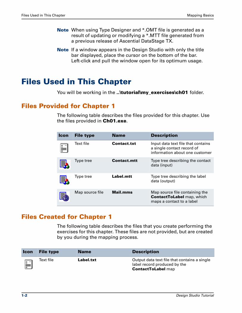
Files Provided for Chapter 1The following table describes the files provided for this chapter. Use
the files provided in Ch01.exe.
Files Created for Chapter 1The following table describes the files that you create performing the
exercises for this chapter. These files are not provided, but are created
by you during the mapping process.
Icon File type Name Description
Text file Contact.txt Input data text file that contains a single contact record of information about one customer
Type tree Contact.mtt Type tree describing the contact data (input)
Type tree Label.mtt Type tree describing the label data (output)
Map source file Mail.mms Map source file containing the ContactToLabel map, which maps a contact to a label
Icon File type Name Description
Text file Label.txt Output data text file that contains a single label record produced by the ContactToLabel map
1-2 Design Studio Tutorial
Mapping Basics Scenario
The default behavior is to create backup files with the .bak filename
extension when each type tree file or map source file is saved.
Copies of the files created during the exercises are provided for all
chapters in the install_dir\tutorial\solutions folder. The structure
and use of these files is described in "Design Studio Tutorial
Solutions" on page xxii in the Introduction section of this document.
ScenarioYou have a simple Contact.txt text file consisting of one record that
contains information about a customer. Using the file as input, you
need to generate a mailing label for this customer.
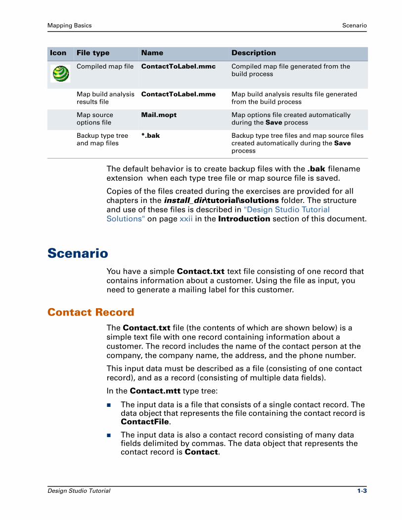
Contact RecordThe Contact.txt file (the contents of which are shown below) is a
simple text file with one record containing information about a
customer. The record includes the name of the contact person at the
company, the company name, the address, and the phone number.
This input data must be described as a file (consisting of one contact
record), and as a record (consisting of multiple data fields).
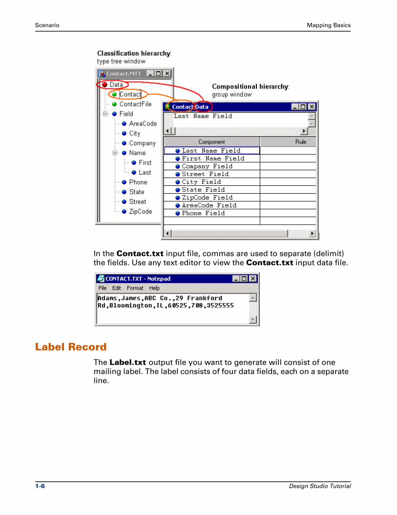
In the Contact.mtt type tree:
The input data is a file that consists of a single contact record. The data object that represents the file containing the contact record is ContactFile.
The input data is also a contact record consisting of many data fields delimited by commas. The data object that represents the contact record is Contact.
Compiled map file ContactToLabel.mmc Compiled map file generated from the build process
Map build analysis results file
ContactToLabel.mme Map build analysis results file generated from the build process
Map source options file
Mail.mopt Map options file created automatically during the Save process
Backup type tree and map files
*.bak Backup type tree files and map source files created automatically during the Save process
Icon File type Name Description
Design Studio Tutorial 1-3
Scenario Mapping Basics
The Type Designer is the design component used to specify, define,
and manage type definitions. Type trees are maintained and created
in the Type Designer, although type trees can also be created using
the Type Tree Maker, the Importer Wizard in the Type Designer, and
the Database Interface Designer.
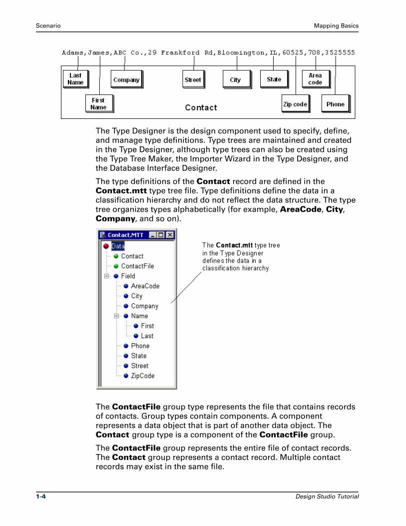
The type definitions of the Contact record are defined in the
Contact.mtt type tree file. Type definitions define the data in a
classification hierarchy and do not reflect the data structure. The type
tree organizes types alphabetically (for example, AreaCode, City,
Company, and so on).
The ContactFile group type represents the file that contains records
of contacts. Group types contain components. A component
represents a data object that is part of another data object. The
Contact group type is a component of the ContactFile group.
The ContactFile group represents the entire file of contact records.
The Contact group represents a contact record. Multiple contact
records may exist in the same file.
1-4 Design Studio Tutorial
Mapping Basics Scenario
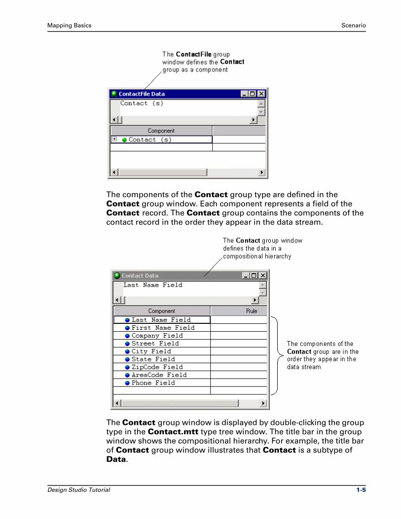
The components of the Contact group type are defined in the
Contact group window. Each component represents a field of the
Contact record. The Contact group contains the components of the
contact record in the order they appear in the data stream.
The Contact group window is displayed by double-clicking the group
type in the Contact.mtt type tree window. The title bar in the group
window shows the compositional hierarchy. For example, the title bar
of Contact group window illustrates that Contact is a subtype of
Data.
Design Studio Tutorial 1-5
Scenario Mapping Basics
In the Contact.txt input file, commas are used to separate (delimit)
the fields. Use any text editor to view the Contact.txt input data file.
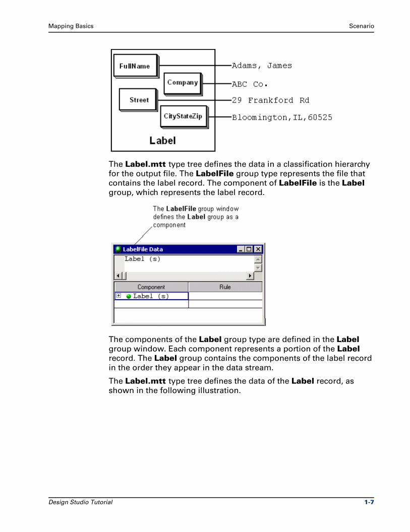
Label RecordThe Label.txt output file you want to generate will consist of one
mailing label. The label consists of four data fields, each on a separate
line.
1-6 Design Studio Tutorial
Mapping Basics Scenario
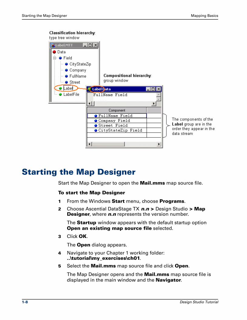
The Label.mtt type tree defines the data in a classification hierarchy
for the output file. The LabelFile group type represents the file that
contains the label record. The component of LabelFile is the Label group, which represents the label record.
The components of the Label group type are defined in the Label group window. Each component represents a portion of the Label record. The Label group contains the components of the label record
in the order they appear in the data stream.
The Label.mtt type tree defines the data of the Label record, as
shown in the following illustration.
Design Studio Tutorial 1-7
Starting the Map Designer Mapping Basics
Starting the Map DesignerStart the Map Designer to open the Mail.mms map source file.
To start the Map Designer
1 From the Windows Start menu, choose Programs.
2 Choose Ascential DataStage TX n.n > Design Studio > Map Designer, where n.n represents the version number.
The Startup window appears with the default startup option
Open an existing map source file selected.
3 Click OK.
The Open dialog appears.
4 Navigate to your Chapter 1 working folder: ..\tutorial\my_exercises\ch01.
5 Select the Mail.mms map source file and click Open.
The Map Designer opens and the Mail.mms map source file is
displayed in the main window and the Navigator.
1-8 Design Studio Tutorial
Mapping Basics Starting the Map Designer
Note The installation program adds an entry for the Map
Designer to the Ascential DataStage TX program folder. If
you do not see the Ascential DataStage TX program on the
Start menu, contact your system administrator.
Exploring the ContactToLabel MapThe ContactToLabel map is contained in the Mail.mms map source
file. The ContactToLabel map contains input and output cards that
transform data content from the Contact record source format to the
Label target format according to the map rules contained in the map.
The Mail.mms map source file is a file that is created and saved using
the commands on the File menu in the Map Designer and has a file
name extension of .mms. The full path of the Mail.mms map source
file appears on the title bar of the Map Designer. The name of the
ContactToLabel map (the current map) also appears on the title bar.
The map icon ( ) and name of the ContactToLabel map appear
under the Mail map source file in the Navigator.
Design Studio Tutorial 1-9
Starting the Map Designer Mapping Basics
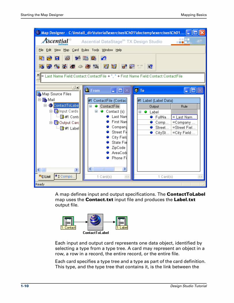
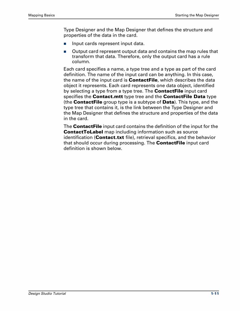
A map defines input and output specifications. The ContactToLabel map uses the Contact.txt input file and produces the Label.txt
output file.
Each input and output card represents one data object, identified by
selecting a type from a type tree. A card may represent an object in a
row, a row in a record, the entire record, or the entire file.
Each card specifies a type tree and a type as part of the card definition.
This type, and the type tree that contains it, is the link between the
1-10 Design Studio Tutorial
Mapping Basics Starting the Map Designer
Type Designer and the Map Designer that defines the structure and
properties of the data in the card.
Input cards represent input data.
Output card represent output data and contains the map rules that transform that data. Therefore, only the output card has a rule column.
Each card specifies a name, a type tree and a type as part of the card
definition. The name of the input card can be anything. In this case,
the name of the input card is ContactFile, which describes the data
object it represents. Each card represents one data object, identified
by selecting a type from a type tree. The ContactFile input card
specifies the Contact.mtt type tree and the ContactFile Data type
(the ContactFile group type is a subtype of Data). This type, and the
type tree that contains it, is the link between the Type Designer and
the Map Designer that defines the structure and properties of the data
in the card.
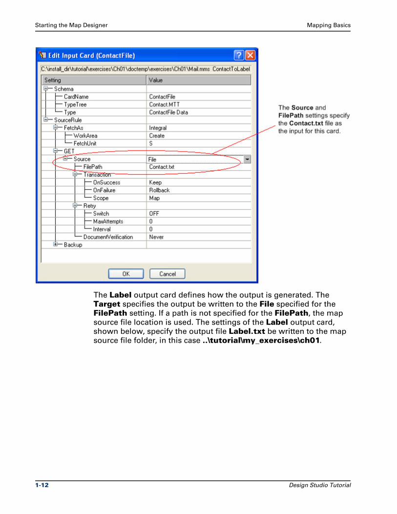
The ContactFile input card contains the definition of the input for the
ContactToLabel map including information such as source
identification (Contact.txt file), retrieval specifics, and the behavior
that should occur during processing. The ContactFile input card
definition is shown below.
Design Studio Tutorial 1-11
Starting the Map Designer Mapping Basics
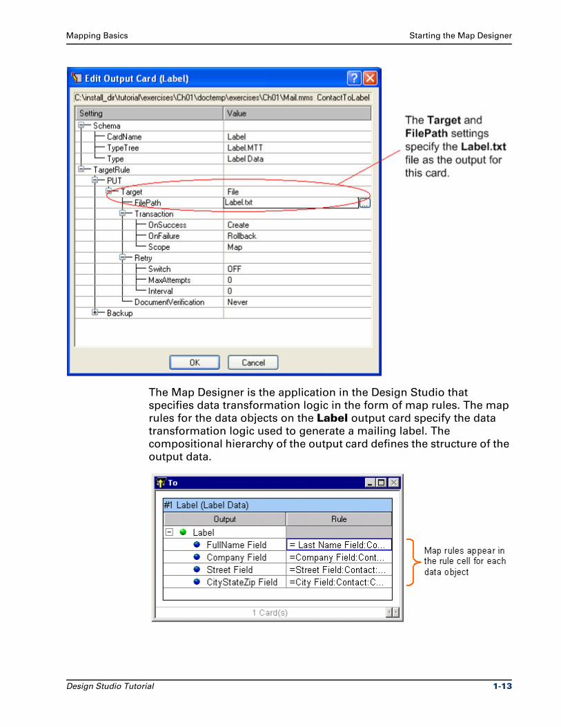
The Label output card defines how the output is generated. The
Target specifies the output be written to the File specified for the
FilePath setting. If a path is not specified for the FilePath, the map
source file location is used. The settings of the Label output card,
shown below, specify the output file Label.txt be written to the map
source file folder, in this case ..\tutorial\my_exercises\ch01.
1-12 Design Studio Tutorial
Mapping Basics Starting the Map Designer
The Map Designer is the application in the Design Studio that
specifies data transformation logic in the form of map rules. The map
rules for the data objects on the Label output card specify the data
transformation logic used to generate a mailing label. The
compositional hierarchy of the output card defines the structure of the
output data.
Design Studio Tutorial 1-13
Starting the Map Designer Mapping Basics
The Label output card represents the Label group type. The Label group contains the components that define the fields of the Label record (such as Full Name, Company, and so on). Components are
listed from top to bottom in the order they appear in the data stream.
The structure of the output card defines the data in a compositional
hierarchy.
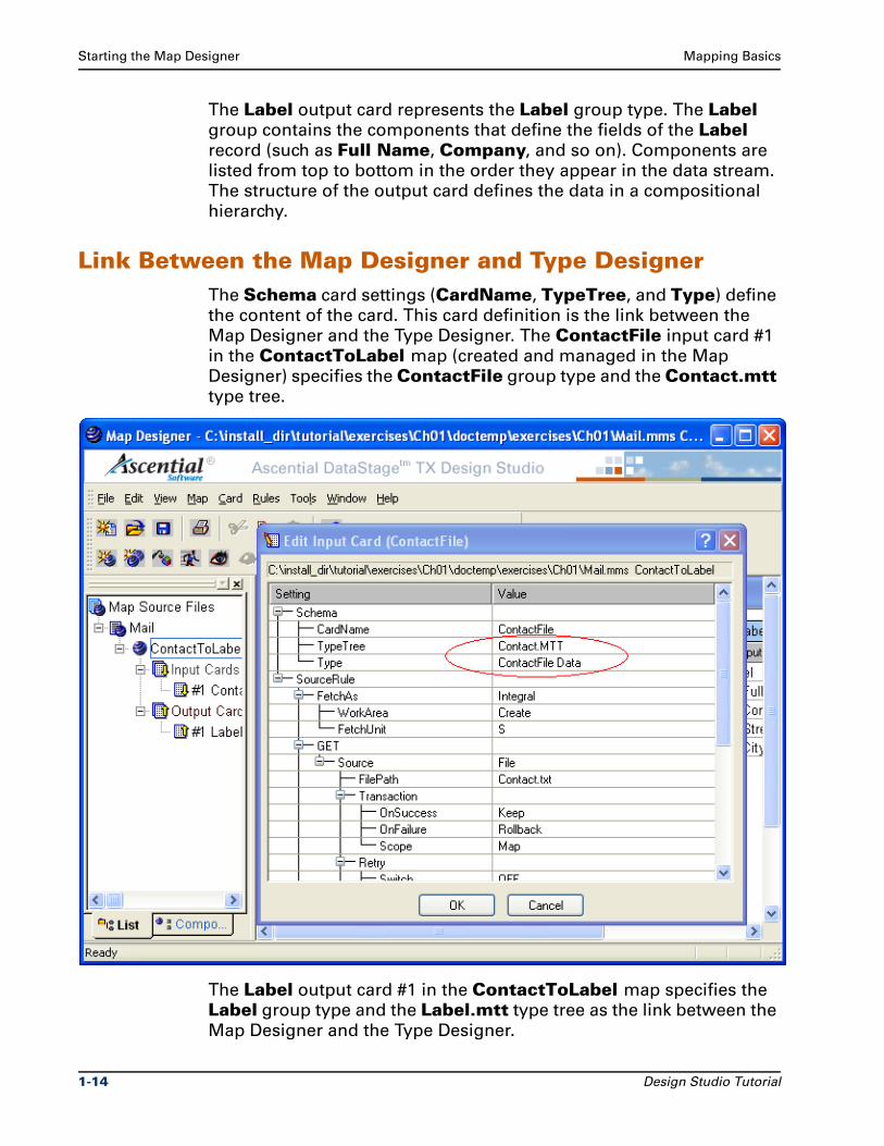
Link Between the Map Designer and Type DesignerThe Schema card settings (CardName, TypeTree, and Type) define
the content of the card. This card definition is the link between the
Map Designer and the Type Designer. The ContactFile input card #1
in the ContactToLabel map (created and managed in the Map
Designer) specifies the ContactFile group type and the Contact.mtt
type tree.
The Label output card #1 in the ContactToLabel map specifies the
Label group type and the Label.mtt type tree as the link between the
Map Designer and the Type Designer.
1-14 Design Studio Tutorial
Mapping Basics Viewing Components in the ContactToLabel Map
Viewing Components in the ContactToLabel Map
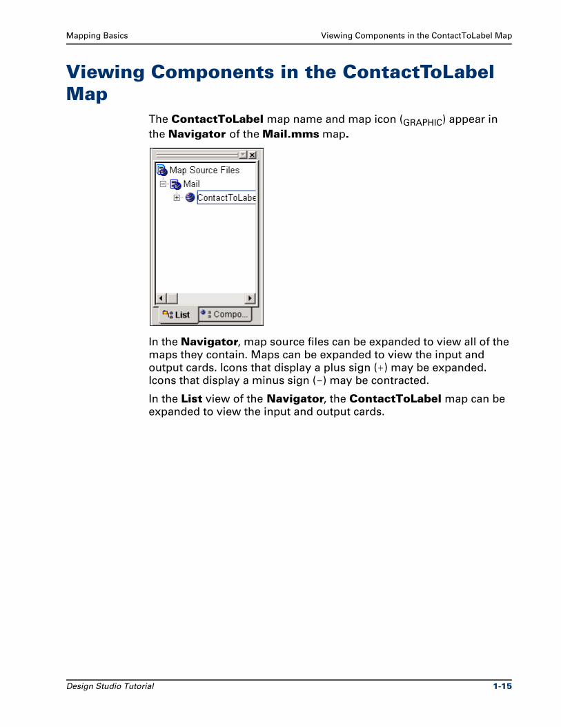
The ContactToLabel map name and map icon (GRAPHIC) appear in
the Navigator of the Mail.mms map.
In the Navigator, map source files can be expanded to view all of the
maps they contain. Maps can be expanded to view the input and
output cards. Icons that display a plus sign (+) may be expanded.
Icons that display a minus sign (-) may be contracted.
In the List view of the Navigator, the ContactToLabel map can be
expanded to view the input and output cards.
Design Studio Tutorial 1-15
Viewing Components in the ContactToLabel Map Mapping Basics
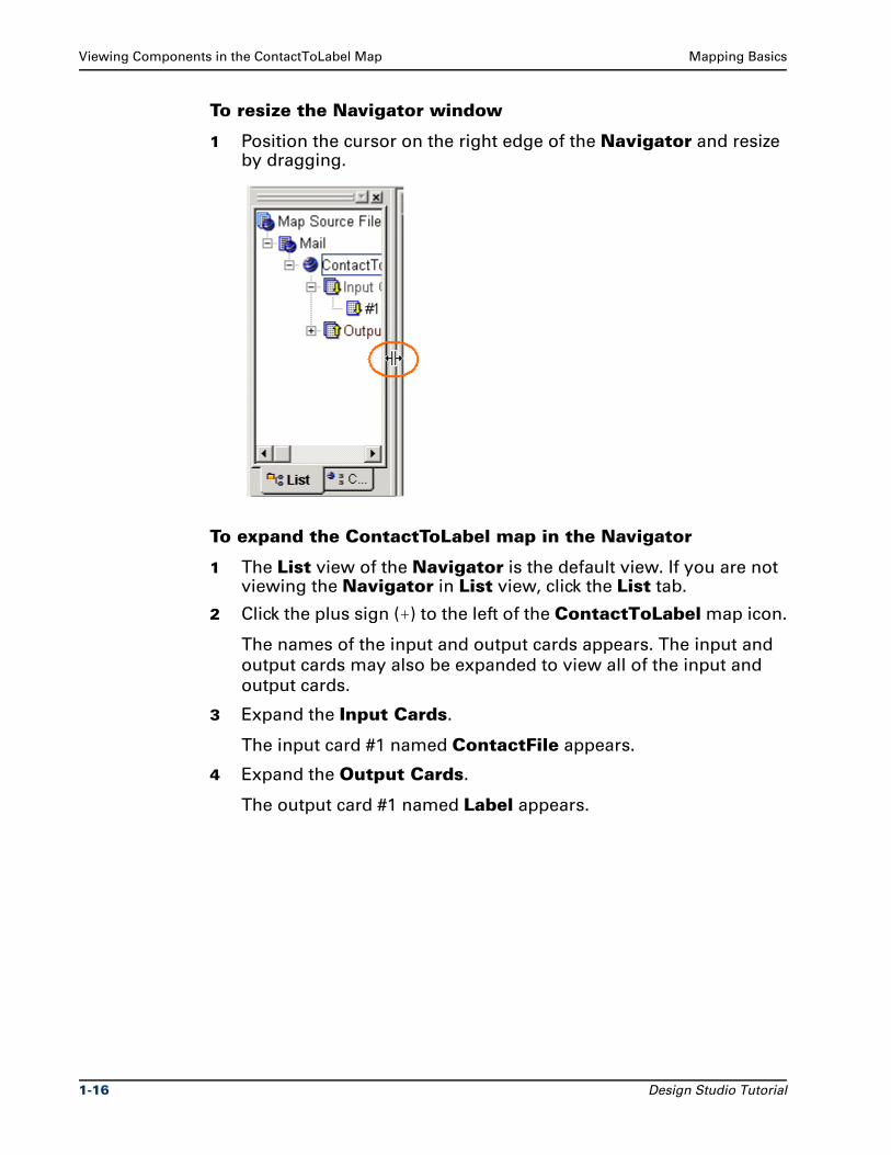
To resize the Navigator window
1 Position the cursor on the right edge of the Navigator and resize by dragging.
To expand the ContactToLabel map in the Navigator
1 The List view of the Navigator is the default view. If you are not viewing the Navigator in List view, click the List tab.
2 Click the plus sign (+) to the left of the ContactToLabel map icon.
The names of the input and output cards appears. The input and
output cards may also be expanded to view all of the input and
output cards.
3 Expand the Input Cards.
The input card #1 named ContactFile appears.
4 Expand the Output Cards.
The output card #1 named Label appears.
1-16 Design Studio Tutorial
Mapping Basics Viewing Components in the ContactToLabel Map
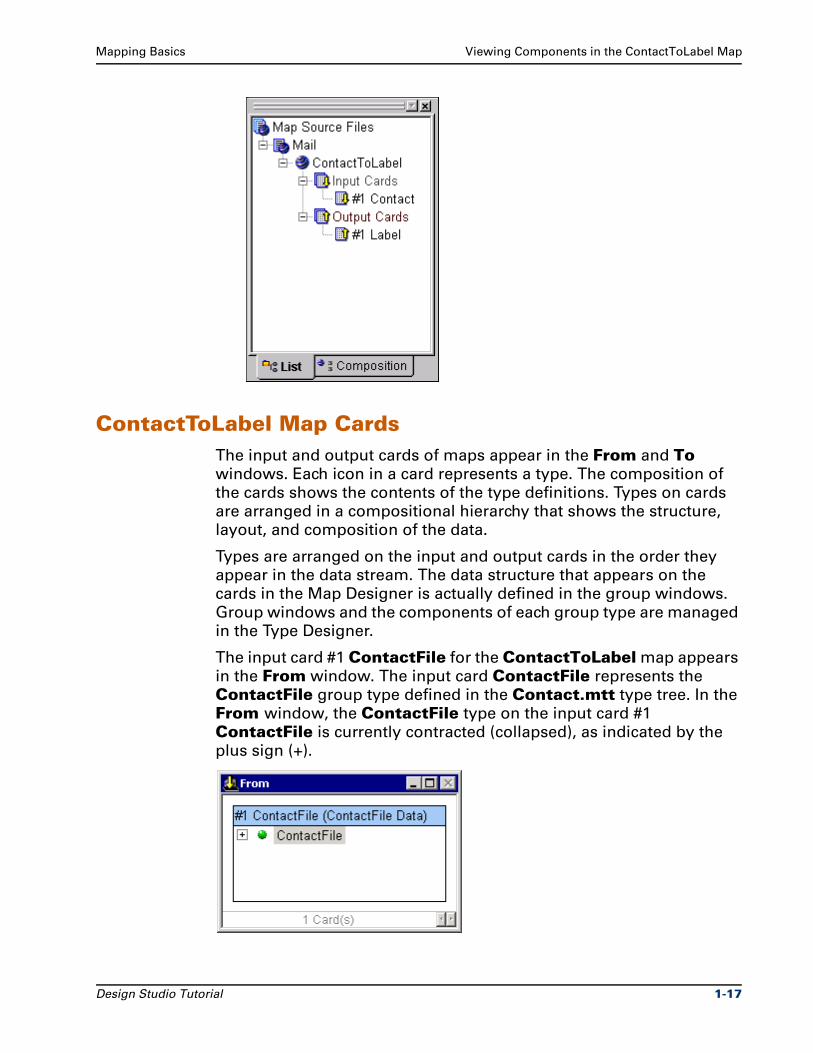
ContactToLabel Map CardsThe input and output cards of maps appear in the From and To
windows. Each icon in a card represents a type. The composition of
the cards shows the contents of the type definitions. Types on cards
are arranged in a compositional hierarchy that shows the structure,
layout, and composition of the data.
Types are arranged on the input and output cards in the order they
appear in the data stream. The data structure that appears on the
cards in the Map Designer is actually defined in the group windows.
Group windows and the components of each group type are managed
in the Type Designer.
The input card #1 ContactFile for the ContactToLabel map appears
in the From window. The input card ContactFile represents the
ContactFile group type defined in the Contact.mtt type tree. In the
From window, the ContactFile type on the input card #1
ContactFile is currently contracted (collapsed), as indicated by the
plus sign (+).
Design Studio Tutorial 1-17
Viewing Components in the ContactToLabel Map Mapping Basics
The output card #1 Label appears in the To window. The To window
represents the output data to which you are mapping. The output card
#1 Label is displayed in the To window. The output card Label represents the Label group type defined in the Label.mtt type tree.
In the To window, the Label type on the output card #1 Label is
currently expanded to display the map rules on the data objects
contained in the Label card.
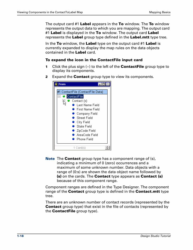
To expand the icon in the ContactFile input card
1 Click the plus sign (+) to the left of the ContactFile group type to display its components.
2 Expand the Contact group type to view its components.
Note The Contact group type has a component range of (s),
indicating a minimum of 0 (zero) occurrences and a
maximum of some unknown number. Data objects with a
range of (0:s) are shown the data object name followed by
(s) on the cards. The Contact type appears as Contact (s) because of this component range.
Component ranges are defined in the Type Designer. The component
range of the Contact group type is defined in the Contact.mtt type
tree.
There are an unknown number of contact records (represented by the
Contact group type) that exist in the file of contacts (represented by
the ContactFile group type).
1-18 Design Studio Tutorial
Mapping Basics Map Rules
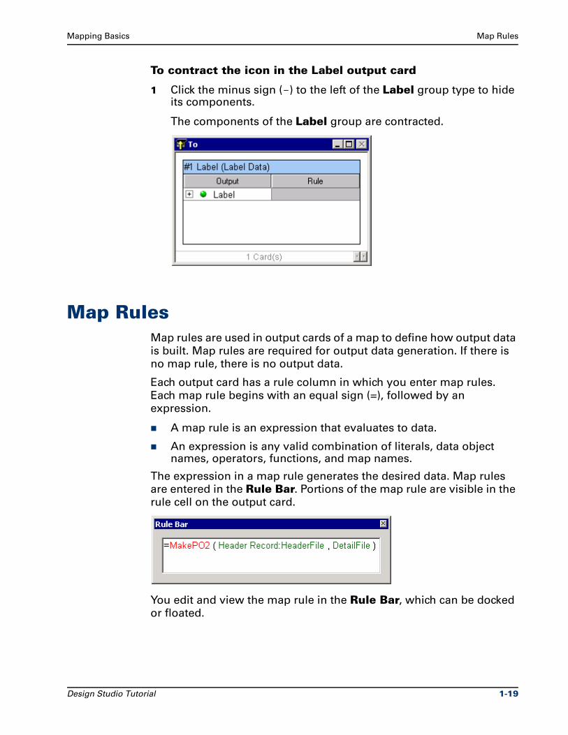
To contract the icon in the Label output card
1 Click the minus sign (-) to the left of the Label group type to hide its components.
The components of the Label group are contracted.
Map RulesMap rules are used in output cards of a map to define how output data
is built. Map rules are required for output data generation. If there is
no map rule, there is no output data.
Each output card has a rule column in which you enter map rules.
Each map rule begins with an equal sign (=), followed by an
expression.
A map rule is an expression that evaluates to data.
An expression is any valid combination of literals, data object names, operators, functions, and map names.
The expression in a map rule generates the desired data. Map rules
are entered in the Rule Bar. Portions of the map rule are visible in the
rule cell on the output card.
You edit and view the map rule in the Rule Bar, which can be docked
or floated.
Design Studio Tutorial 1-19
Map Rules Mapping Basics
Data Object Names in Map RulesIn map rules, type names separated by a colon indicate a component
relationship. Type names separated by a space indicate a subtype
relationship.
For example, City Field:Contact indicates that City is a subtype of
Field. City Field is a component of Contact.
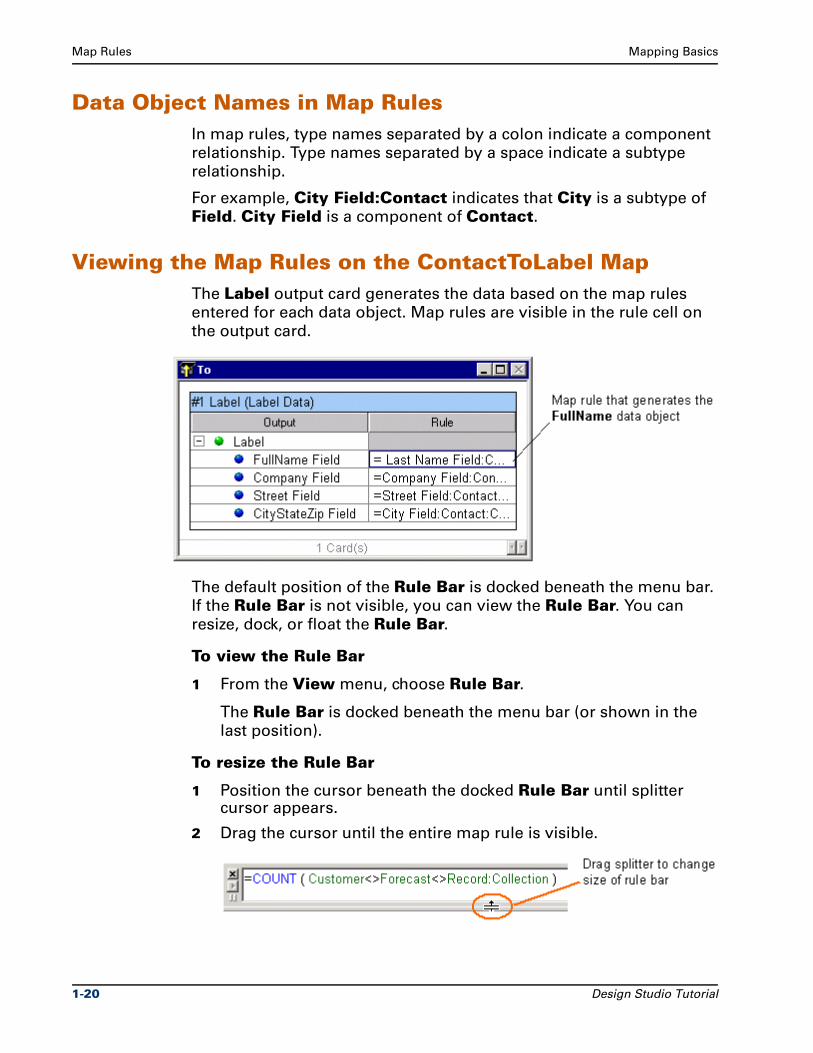
Viewing the Map Rules on the ContactToLabel MapThe Label output card generates the data based on the map rules
entered for each data object. Map rules are visible in the rule cell on
the output card.
The default position of the Rule Bar is docked beneath the menu bar.
If the Rule Bar is not visible, you can view the Rule Bar. You can
resize, dock, or float the Rule Bar.
To view the Rule Bar
1 From the View menu, choose Rule Bar.
The Rule Bar is docked beneath the menu bar (or shown in the
last position).
To resize the Rule Bar
1 Position the cursor beneath the docked Rule Bar until splitter cursor appears.
2 Drag the cursor until the entire map rule is visible.
1-20 Design Studio Tutorial
Mapping Basics Map Rules
Using the NavigatorThe Navigator window and icons graphically represent all of your
opened map source files and the maps that they contain. It also
provides a graphical representation of the input and output cards in
the maps.
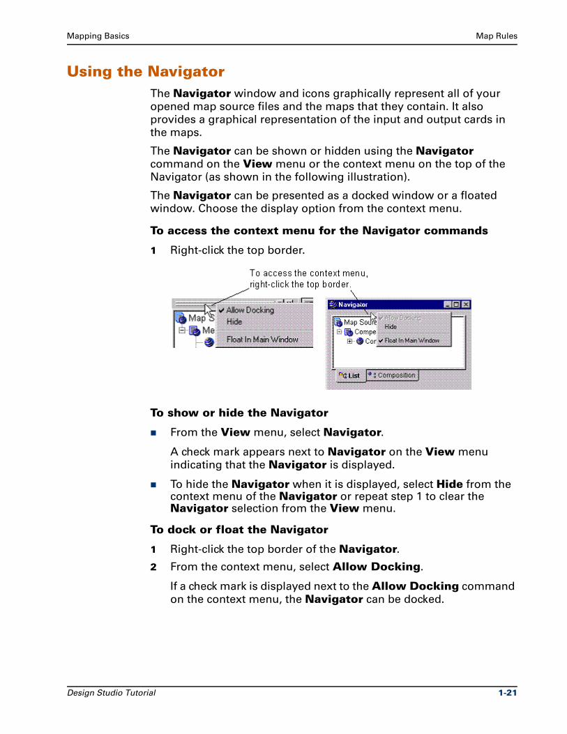
The Navigator can be shown or hidden using the Navigator
command on the View menu or the context menu on the top of the
Navigator (as shown in the following illustration).
The Navigator can be presented as a docked window or a floated
window. Choose the display option from the context menu.
To access the context menu for the Navigator commands
1 Right-click the top border.
To show or hide the Navigator
From the View menu, select Navigator.
A check mark appears next to Navigator on the View menu
indicating that the Navigator is displayed.
To hide the Navigator when it is displayed, select Hide from the context menu of the Navigator or repeat step 1 to clear the Navigator selection from the View menu.
To dock or float the Navigator
1 Right-click the top border of the Navigator.
2 From the context menu, select Allow Docking.
If a check mark is displayed next to the Allow Docking command
on the context menu, the Navigator can be docked.
Design Studio Tutorial 1-21
Building the ContactToLabel Map Mapping Basics
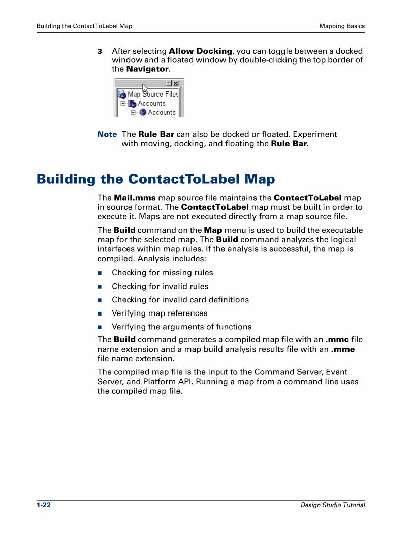
3 After selecting Allow Docking, you can toggle between a docked window and a floated window by double-clicking the top border of the Navigator.
Note The Rule Bar can also be docked or floated. Experiment
with moving, docking, and floating the Rule Bar.
Building the ContactToLabel MapThe Mail.mms map source file maintains the ContactToLabel map
in source format. The ContactToLabel map must be built in order to
execute it. Maps are not executed directly from a map source file.
The Build command on the Map menu is used to build the executable
map for the selected map. The Build command analyzes the logical
interfaces within map rules. If the analysis is successful, the map is
compiled. Analysis includes:
Checking for missing rules
Checking for invalid rules
Checking for invalid card definitions
Verifying map references
Verifying the arguments of functions
The Build command generates a compiled map file with an .mmc file
name extension and a map build analysis results file with an .mme
file name extension.
The compiled map file is the input to the Command Server, Event
Server, and Platform API. Running a map from a command line uses
the compiled map file.
1-22 Design Studio Tutorial
Mapping Basics Building the ContactToLabel Map
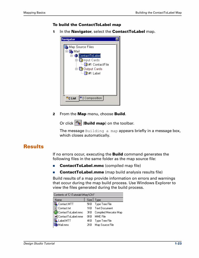
To build the ContactToLabel map
1 In the Navigator, select the ContactToLabel map.
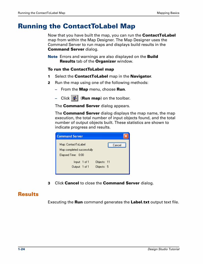
2 From the Map menu, choose Build.
Or click (Build map) on the toolbar.
The message Building a map appears briefly in a message box,
which closes automatically.
ResultsIf no errors occur, executing the Build command generates the
following files in the same folder as the map source file:
ContactToLabel.mmc (compiled map file)
ContactToLabel.mme (map build analysis results file)
Build results of a map provide information on errors and warnings
that occur during the map build process. Use Windows Explorer to
view the files generated during the build process.
Design Studio Tutorial 1-23
Running the ContactToLabel Map Mapping Basics
Running the ContactToLabel MapNow that you have built the map, you can run the ContactToLabel map from within the Map Designer. The Map Designer uses the
Command Server to run maps and displays build results in the
Command Server dialog.
Note Errors and warnings are also displayed on the Build Results tab of the Organizer window.
To run the ContactToLabel map
1 Select the ContactToLabel map in the Navigator.
2 Run the map using one of the following methods:
– From the Map menu, choose Run.
– Click (Run map) on the toolbar.
The Command Server dialog appears.
The Command Server dialog displays the map name, the map
execution, the total number of input objects found, and the total
number of output objects built. These statistics are shown to
indicate progress and results.
3 Click Cancel to close the Command Server dialog.
ResultsExecuting the Run command generates the Label.txt output text file.
1-24 Design Studio Tutorial
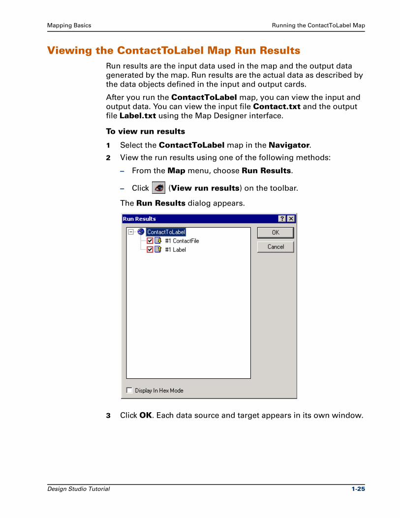
Mapping Basics Running the ContactToLabel Map
Viewing the ContactToLabel Map Run ResultsRun results are the input data used in the map and the output data
generated by the map. Run results are the actual data as described by
the data objects defined in the input and output cards.
After you run the ContactToLabel map, you can view the input and
output data. You can view the input file Contact.txt and the output
file Label.txt using the Map Designer interface.
To view run results
1 Select the ContactToLabel map in the Navigator.
2 View the run results using one of the following methods:
– From the Map menu, choose Run Results.
– Click (View run results) on the toolbar.
The Run Results dialog appears.
3 Click OK. Each data source and target appears in its own window.
Design Studio Tutorial 1-25
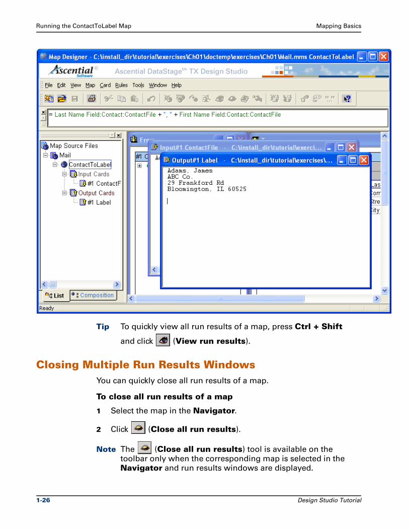
Running the ContactToLabel Map Mapping Basics
Tip To quickly view all run results of a map, press Ctrl + Shift
and click (View run results).
Closing Multiple Run Results WindowsYou can quickly close all run results of a map.
To close all run results of a map
1 Select the map in the Navigator.
2 Click (Close all run results).
Note The (Close all run results) tool is available on the
toolbar only when the corresponding map is selected in the
Navigator and run results windows are displayed.
1-26 Design Studio Tutorial
Mapping Basics Summary
The position of the run results windows is retained for each map. The
next time the run results are viewed, the run results windows appear
in the same position. The mapname.mopt file contains map-specific
options. The .mopt file is created in the map folder when the map is
saved.
You can close multiple data windows at once.
To close all data windows
1 From the Window menu, choose Close All.
SummaryThe Mail.mms map source file contains the ContactToLabel map.
Input cards define the source of the map. Output cards define the
target of the map.
ContactToLabel Map SourceThe contact.txt file containing a simple contact record is the input for the ContactToLabel map.
The structure of this Contact record is defined in the Contact.mtt type tree.
The ContactFile group type defines the Contact group type as a component. The file of contacts contains contact records.
The Contact group type defines the components of the Contact record.
The components of the Contact group type are arranged in the order they appear in the data stream.
Design Studio Tutorial 1-27
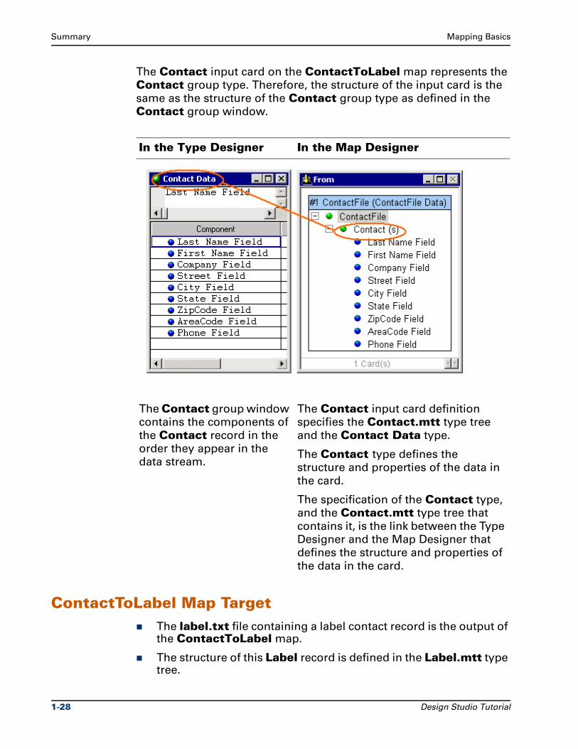
Summary Mapping Basics
The Contact input card on the ContactToLabel map represents the
Contact group type. Therefore, the structure of the input card is the
same as the structure of the Contact group type as defined in the
Contact group window.
ContactToLabel Map TargetThe label.txt file containing a label contact record is the output of the ContactToLabel map.
The structure of this Label record is defined in the Label.mtt type tree.
In the Type Designer In the Map Designer
The Contact group window
contains the components of
the Contact record in the
order they appear in the
data stream.
The Contact input card definition
specifies the Contact.mtt type tree
and the Contact Data type.
The Contact type defines the
structure and properties of the data in
the card.
The specification of the Contact type,
and the Contact.mtt type tree that
contains it, is the link between the Type
Designer and the Map Designer that
defines the structure and properties of
the data in the card.
1-28 Design Studio Tutorial
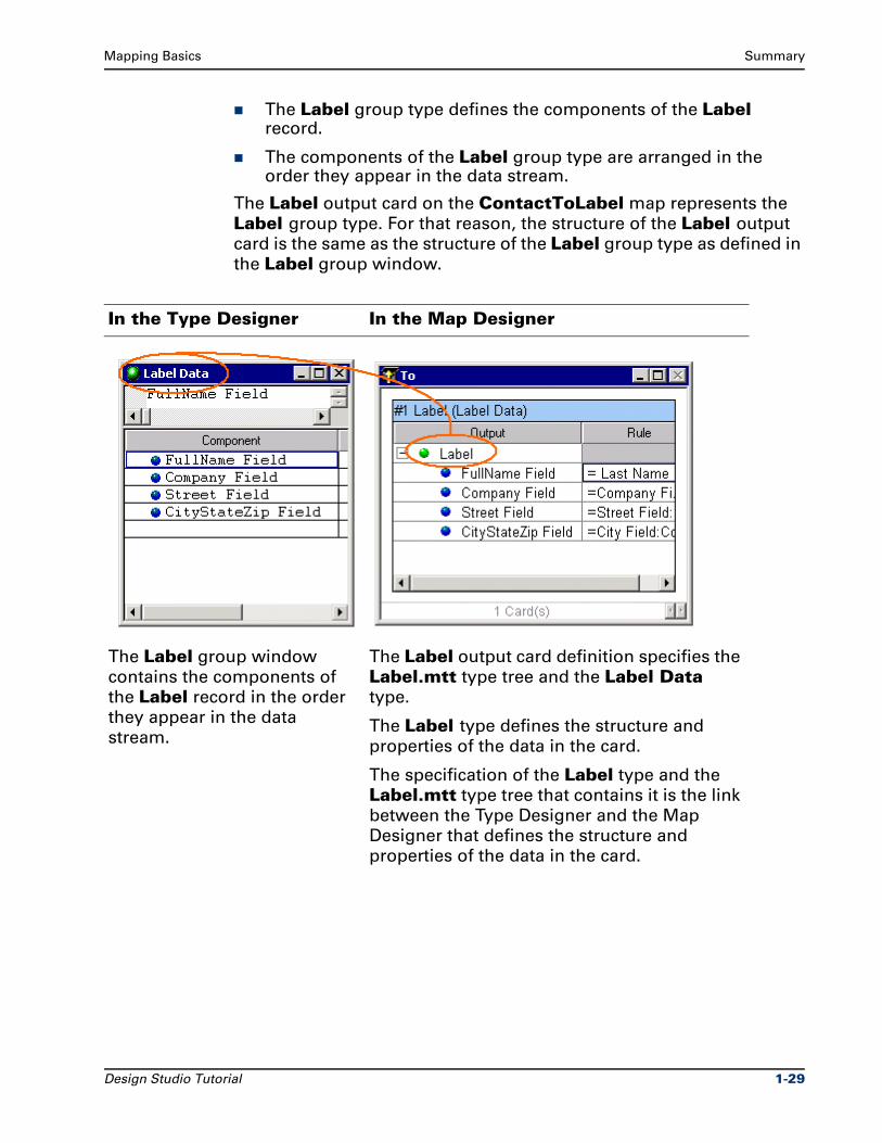
Mapping Basics Summary
The Label group type defines the components of the Label record.
The components of the Label group type are arranged in the order they appear in the data stream.
The Label output card on the ContactToLabel map represents the
Label group type. For that reason, the structure of the Label output
card is the same as the structure of the Label group type as defined in
the Label group window.
In the Type Designer In the Map Designer
The Label group window
contains the components of
the Label record in the order
they appear in the data
stream.
The Label output card definition specifies the
Label.mtt type tree and the Label Data type.
The Label type defines the structure and
properties of the data in the card.
The specification of the Label type and the
Label.mtt type tree that contains it is the link
between the Type Designer and the Map
Designer that defines the structure and
properties of the data in the card.
Design Studio Tutorial 1-29

Summary Mapping Basics
1-30 Design Studio Tutorial
2Modifying the Contact Type Tree
The ContactToLabel map introduced in Chapter 1 uses a single
Customer record to generate a single mailing label. The
Contact.mtt type tree represents the input data. The Customer
record in Chapter 1 did not have a middle name or initial.
In this exercise, you modify the input Contact.mtt type tree to add a
definition for the middle name field.
ObjectivesThis exercise modifies an existing type tree and introduces
component ranges.
By completing the exercises for Chapter 2, you will learn how to use
the Type Designer to:
View and understand type properties.
View associated input data file.
Open and close group windows components.
Modify a type tree to create a new data field.
Add a component to a group type.
Add a component range to an optional component.
Access Help for a field in a dialog.
Analyze and save a type tree.
Design Studio Tutorial 2-1
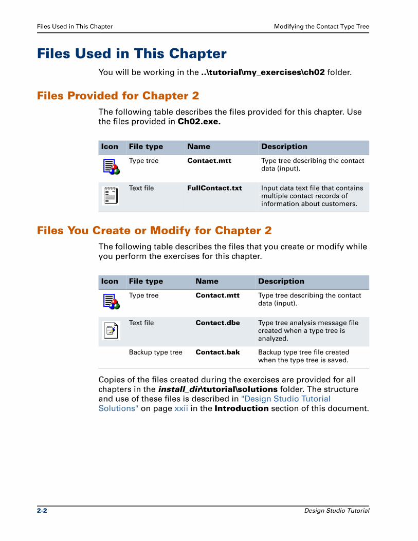
Files Used in This Chapter Modifying the Contact Type Tree
Files Used in This ChapterYou will be working in the ..\tutorial\my_exercises\ch02 folder.
Files Provided for Chapter 2The following table describes the files provided for this chapter. Use
the files provided in Ch02.exe.
Files You Create or Modify for Chapter 2The following table describes the files that you create or modify while
you perform the exercises for this chapter.
Copies of the files created during the exercises are provided for all
chapters in the install_dir\tutorial\solutions folder. The structure
and use of these files is described in "Design Studio Tutorial
Solutions" on page xxii in the Introduction section of this document.
Icon File type Name Description
Type tree Contact.mtt Type tree describing the contact data (input).
Text file FullContact.txt Input data text file that contains multiple contact records of information about customers.
Icon File type Name Description
Type tree Contact.mtt Type tree describing the contact data (input).
Text file Contact.dbe Type tree analysis message file created when a type tree is analyzed.
Backup type tree Contact.bak Backup type tree file created when the type tree is saved.
2-2 Design Studio Tutorial
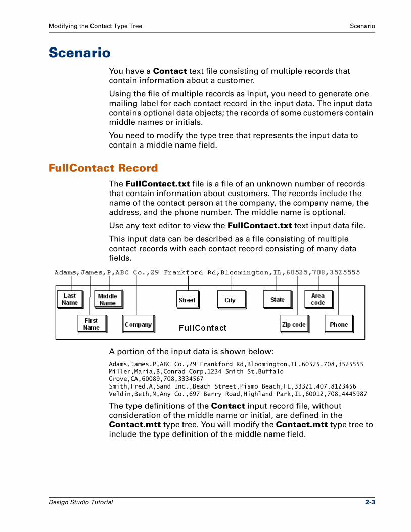
Modifying the Contact Type Tree Scenario
ScenarioYou have a Contact text file consisting of multiple records that
contain information about a customer.
Using the file of multiple records as input, you need to generate one
mailing label for each contact record in the input data. The input data
contains optional data objects; the records of some customers contain
middle names or initials.
You need to modify the type tree that represents the input data to
contain a middle name field.
FullContact RecordThe FullContact.txt file is a file of an unknown number of records
that contain information about customers. The records include the
name of the contact person at the company, the company name, the
address, and the phone number. The middle name is optional.
Use any text editor to view the FullContact.txt text input data file.
This input data can be described as a file consisting of multiple
contact records with each contact record consisting of many data
fields.
A portion of the input data is shown below:
Adams,James,P,ABC Co.,29 Frankford Rd,Bloomington,IL,60525,708,3525555Miller,Maria,B,Conrad Corp,1234 Smith St,Buffalo Grove,CA,60089,708,3334567Smith,Fred,A,Sand Inc.,Beach Street,Pismo Beach,FL,33321,407,8123456Veldin,Beth,M,Any Co.,697 Berry Road,Highland Park,IL,60012,708,4445987
The type definitions of the Contact input record file, without
consideration of the middle name or initial, are defined in the
Contact.mtt type tree. You will modify the Contact.mtt type tree to
include the type definition of the middle name field.
Design Studio Tutorial 2-3
Starting the Type Designer Modifying the Contact Type Tree
Label OutputThe output data is a file of mailing labels. We want to generate one
label for every contact record in the input. The labels will consist of
four data fields, each on a separate line.
The labels should look like the following:
James P. AdamsABC Co.29 Frankford RdBloomington, IL 60525
Maria B. MillerConrad Corp1234 Smith StBuffalo Grove, CA 60089
Fred A. SmithSand Inc.Beach StreetPismo Beach, FL 33321
Starting the Type DesignerThe installation program adds an entry for the Type Designer to the
Ascential DataStage TX program folder.
To start the Type Designer
1 From the Windows Start menu, choose Programs.
2 Choose Ascential DataStage TX n.n > Design Studio > Type Designer, where n.n represents the version number.
The Startup dialog appears with the default startup option Open an existing type tree file selected.
3 Click OK.
The Open dialog appears.
4 Navigate to your Chapter 2 working folder: ..\tutorial\my_exercises\ch02.
5 Select the Contact.mtt type tree file and click Open.
The Type Designer opens and the Contact.mtt type tree file is
displayed in the type tree window.
2-4 Design Studio Tutorial
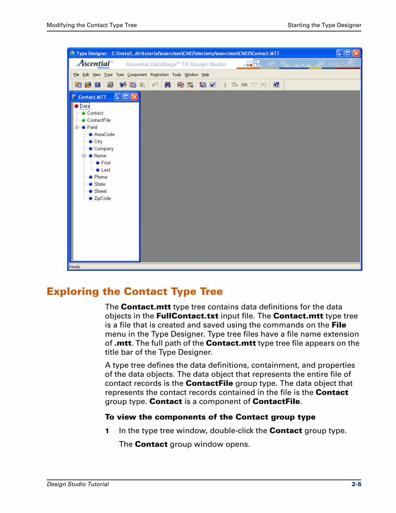
Modifying the Contact Type Tree Starting the Type Designer
Exploring the Contact Type TreeThe Contact.mtt type tree contains data definitions for the data
objects in the FullContact.txt input file. The Contact.mtt type tree
is a file that is created and saved using the commands on the File
menu in the Type Designer. Type tree files have a file name extension
of .mtt. The full path of the Contact.mtt type tree file appears on the
title bar of the Type Designer.
A type tree defines the data definitions, containment, and properties
of the data objects. The data object that represents the entire file of
contact records is the ContactFile group type. The data object that
represents the contact records contained in the file is the Contact
group type. Contact is a component of ContactFile.
To view the components of the Contact group type
1 In the type tree window, double-click the Contact group type.
The Contact group window opens.
Design Studio Tutorial 2-5
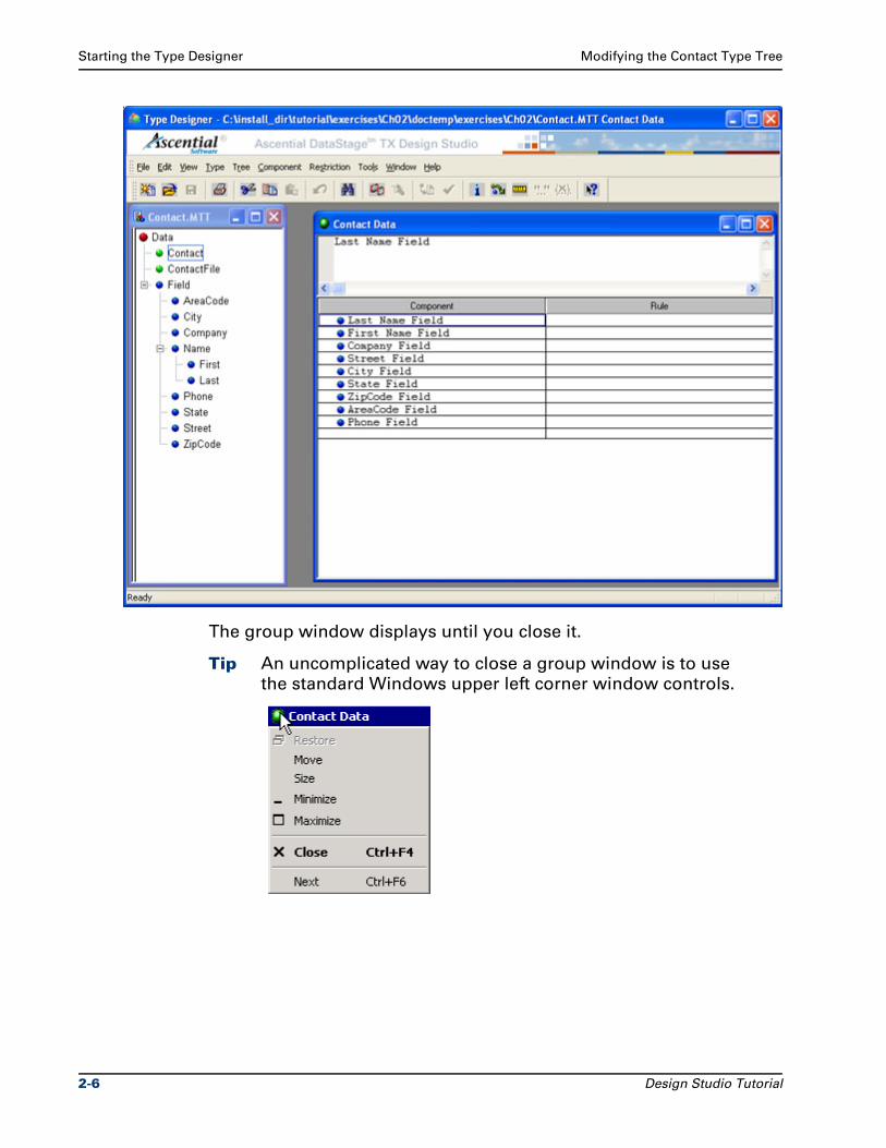
Starting the Type Designer Modifying the Contact Type Tree
The group window displays until you close it.
Tip An uncomplicated way to close a group window is to use
the standard Windows upper left corner window controls.
2-6 Design Studio Tutorial
Modifying the Contact Type Tree Type Properties
To close the Contact group window
1 Double-click the green icon in the left side of the group window title bar.
Type PropertiesThe properties and definitions of all data objects are defined in the
type tree. The properties and definition of each data object in the input
data, and each data object in the output data, must be defined in a
type tree to achieve the desired data transformation. In the type tree
window, the color of the icon in the type tree provides a visual
indication for the Class of the data object.
Category icons are red.
Group icons are green.
Item icons are blue.
Viewing Type PropertiesEach type has properties that define the characteristics of that data
object. You can view or modify any type properties in the Properties window.
Properties that display a plus sign (+) contain related properties that are currently hidden. Click the plus sign (+) to expand and view the related properties.
Properties that display a minus sign (-) contain related properties that are currently shown. Click the minus sign (-) to collapse the properties.
To view the properties of the Contact group type
1 In the type tree window, select the Contact group type.
2 Click (Properties) on the toolbar.
The Properties for Contact Data window appears.
The Properties window may be sized, docked, or floated as needed.
The default position of the Properties window for new type trees is
docked. The title bar for docked windows is not displayed. To view the
title bar, undock the window.
Design Studio Tutorial 2-7
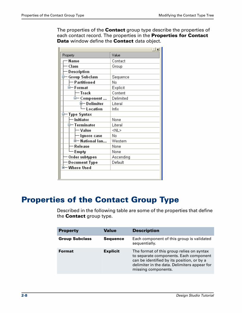
Properties of the Contact Group Type Modifying the Contact Type Tree
The properties of the Contact group type describe the properties of
each contact record. The properties in the Properties for Contact Data window define the Contact data object.
Properties of the Contact Group TypeDescribed in the following table are some of the properties that define
the Contact group type.
Property Value Description
Group Subclass Sequence Each component of this group is validated sequentially.
Format Explicit The format of this group relies on syntax to separate components. Each component can be identified by its position, or by a delimiter in the data. Delimiters appear for missing components.
2-8 Design Studio Tutorial

Modifying the Contact Type Tree Components of Contact
Components of ContactThe Contact group window defines the components of the Contact
input data. The components of the Contact group type define the
data objects for the contact records in the order they appear in the
data stream.
In the Contact group window composition hierarchy shown below,
there is not a data definition for the Middle Name Field.
Component Syntax Delimited The syntax of the Contact group is delimited, where a delimiter in the data separates each component.
Delimiter Literal The literal comma (,) delimiter separates (delimits) the components of each contact record.
Terminator Literal A terminator is a syntax object that appears at the end of a data object. Defining the terminator as literal identifies the terminator as a known constant value.
Value <NL> The value of the literal terminator of the Contact group is <NL> (new line character). This non-platform specific terminator specifies a new line.
For example, for the Contact record on Windows, the <NL> new line character represents a carriage return character followed by a line feed character. For the Contact record on a UNIX system, the <NL> new line character represents a line feed character.
Property Value Description
Design Studio Tutorial 2-9
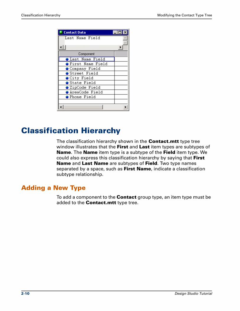
Classification Hierarchy Modifying the Contact Type Tree
Classification HierarchyThe classification hierarchy shown in the Contact.mtt type tree
window illustrates that the First and Last item types are subtypes of
Name. The Name item type is a subtype of the Field item type. We
could also express this classification hierarchy by saying that First Name and Last Name are subtypes of Field. Two type names
separated by a space, such as First Name, indicate a classification
subtype relationship.
Adding a New TypeTo add a component to the Contact group type, an item type must be
added to the Contact.mtt type tree.
2-10 Design Studio Tutorial
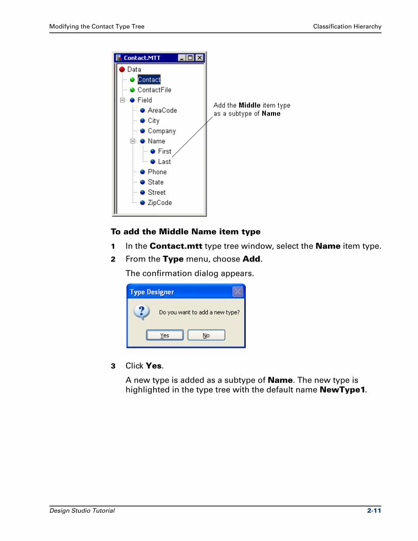
Modifying the Contact Type Tree Classification Hierarchy
To add the Middle Name item type
1 In the Contact.mtt type tree window, select the Name item type.
2 From the Type menu, choose Add.
The confirmation dialog appears.
3 Click Yes.
A new type is added as a subtype of Name. The new type is
highlighted in the type tree with the default name NewType1.
Design Studio Tutorial 2-11
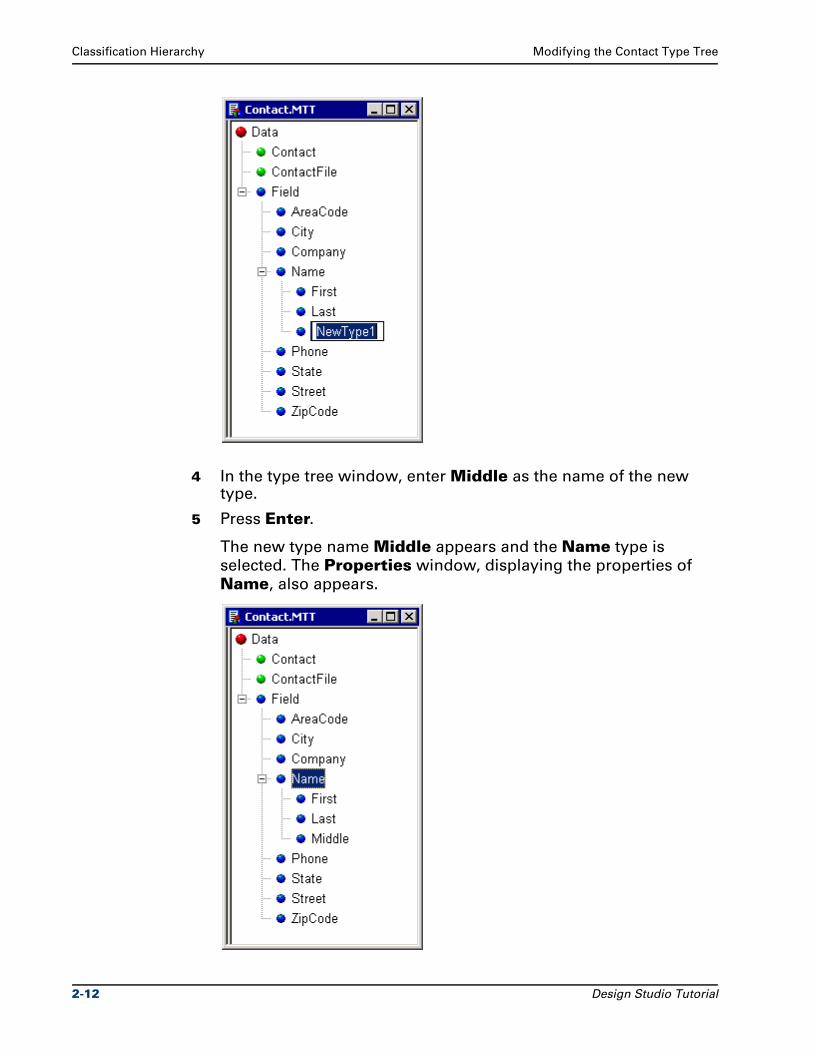
Classification Hierarchy Modifying the Contact Type Tree
4 In the type tree window, enter Middle as the name of the new type.
5 Press Enter.
The new type name Middle appears and the Name type is
selected. The Properties window, displaying the properties of
Name, also appears.
2-12 Design Studio Tutorial
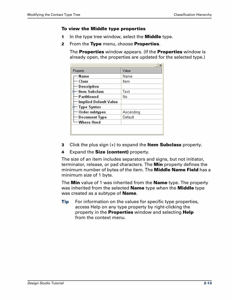
Modifying the Contact Type Tree Classification Hierarchy
To view the Middle type properties
1 In the type tree window, select the Middle type.
2 From the Type menu, choose Properties.
The Properties window appears. (If the Properties window is
already open, the properties are updated for the selected type.)
3 Click the plus sign (+) to expand the Item Subclass property.
4 Expand the Size (content) property.
The size of an item includes separators and signs, but not initiator,
terminator, release, or pad characters. The Min property defines the
minimum number of bytes of the item. The Middle Name Field has a
minimum size of 1 byte.
The Min value of 1 was inherited from the Name type. The property
was inherited from the selected Name type when the Middle type
was created as a subtype of Name.
Tip For information on the values for specific type properties,
access Help on any type property by right-clicking the
property in the Properties window and selecting Help
from the context menu.
Design Studio Tutorial 2-13
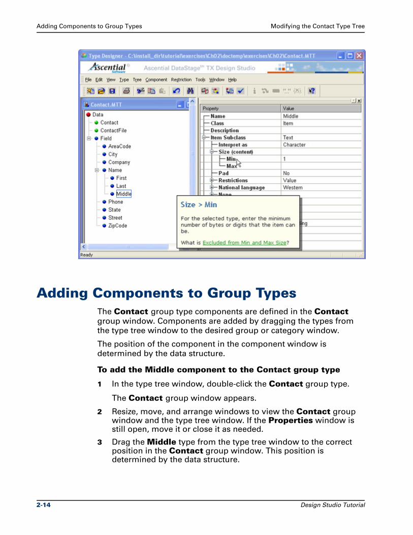
Adding Components to Group Types Modifying the Contact Type Tree
Adding Components to Group TypesThe Contact group type components are defined in the Contact
group window. Components are added by dragging the types from
the type tree window to the desired group or category window.
The position of the component in the component window is
determined by the data structure.
To add the Middle component to the Contact group type
1 In the type tree window, double-click the Contact group type.
The Contact group window appears.
2 Resize, move, and arrange windows to view the Contact group window and the type tree window. If the Properties window is still open, move it or close it as needed.
3 Drag the Middle type from the type tree window to the correct position in the Contact group window. This position is determined by the data structure.
2-14 Design Studio Tutorial
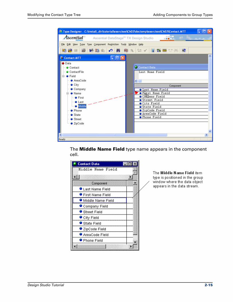
Modifying the Contact Type Tree Adding Components to Group Types
The Middle Name Field type name appears in the component
cell.
Design Studio Tutorial 2-15
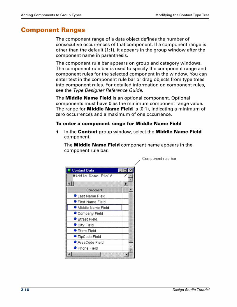
Adding Components to Group Types Modifying the Contact Type Tree
Component RangesThe component range of a data object defines the number of
consecutive occurrences of that component. If a component range is
other than the default (1:1), it appears in the group window after the
component name in parenthesis.
The component rule bar appears on group and category windows.
The component rule bar is used to specify the component range and
component rules for the selected component in the window. You can
enter text in the component rule bar or drag objects from type trees
into component rules. For detailed information on component rules,
see the Type Designer Reference Guide.
The Middle Name Field is an optional component. Optional
components must have 0 as the minimum component range value.
The range for Middle Name Field is (0:1), indicating a minimum of
zero occurrences and a maximum of one occurrence.
To enter a component range for Middle Name Field
1 In the Contact group window, select the Middle Name Field component.
The Middle Name Field component name appears in the
component rule bar.
2-16 Design Studio Tutorial
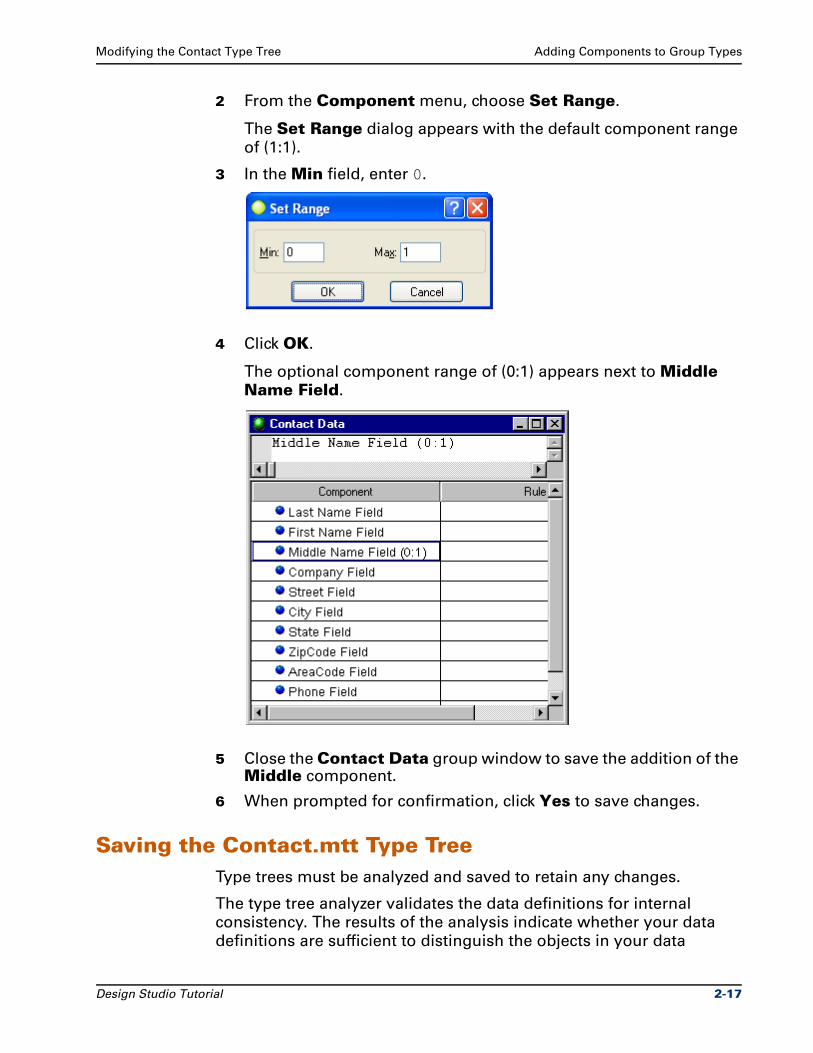
Modifying the Contact Type Tree Adding Components to Group Types
2 From the Component menu, choose Set Range.
The Set Range dialog appears with the default component range
of (1:1).
3 In the Min field, enter 0.
4 Click OK.
The optional component range of (0:1) appears next to Middle Name Field.
5 Close the Contact Data group window to save the addition of the Middle component.
6 When prompted for confirmation, click Yes to save changes.
Saving the Contact.mtt Type TreeType trees must be analyzed and saved to retain any changes.
The type tree analyzer validates the data definitions for internal
consistency. The results of the analysis indicate whether your data
definitions are sufficient to distinguish the objects in your data
Design Studio Tutorial 2-17
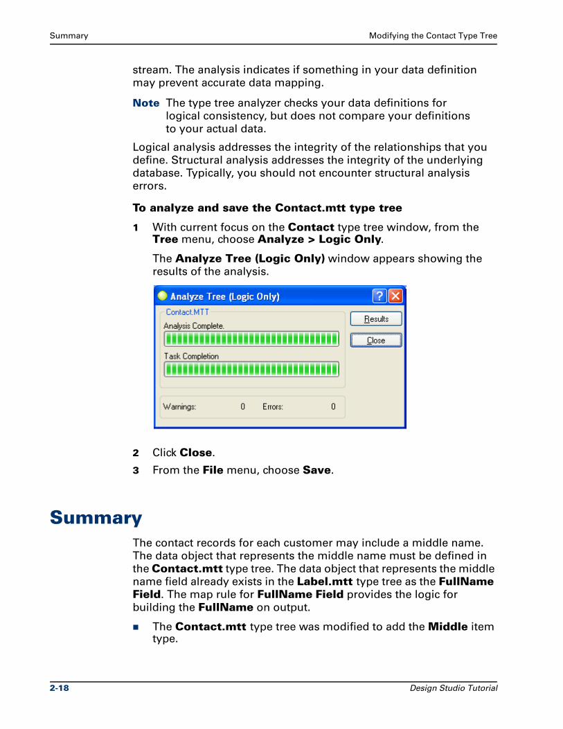
Summary Modifying the Contact Type Tree
stream. The analysis indicates if something in your data definition
may prevent accurate data mapping.
Note The type tree analyzer checks your data definitions for
logical consistency, but does not compare your definitions
to your actual data.
Logical analysis addresses the integrity of the relationships that you
define. Structural analysis addresses the integrity of the underlying
database. Typically, you should not encounter structural analysis
errors.
To analyze and save the Contact.mtt type tree
1 With current focus on the Contact type tree window, from the Tree menu, choose Analyze > Logic Only.
The Analyze Tree (Logic Only) window appears showing the
results of the analysis.
2 Click Close.
3 From the File menu, choose Save.
SummaryThe contact records for each customer may include a middle name.
The data object that represents the middle name must be defined in
the Contact.mtt type tree. The data object that represents the middle
name field already exists in the Label.mtt type tree as the FullName Field. The map rule for FullName Field provides the logic for
building the FullName on output.
The Contact.mtt type tree was modified to add the Middle item type.
2-18 Design Studio Tutorial
Modifying the Contact Type Tree Summary
The Middle item type was added as a component to the Contact group type.
Spaces in type name indicate a subtype relationship in a classification hierarchy. The type name Middle Name Field indicates that Middle is a subtype of Name, and Name is a subtype of Field.
The optional component range of (0:1) was added to the Middle Name Field item type.
The Contact.mtt type tree was analyzed and saved.
Design Studio Tutorial 2-19

Summary Modifying the Contact Type Tree
2-20 Design Studio Tutorial
3Modifying the Mail.mss Map Source
File
The ContactToLabel map introduced in Chapter 1 used a single
customer record to generate a single mailing label. In this exercise,
you copy the ContactToLabel map to a new name in the same
Mail.mms map source file. You map multiple records that may
contain the optional middle names to multiple labels.
After you complete the exercises in this chapter, the Mail.mms map
source file will contain the original ContactToLabel map and the
new ContactToFullLabel map. The ContactToFullLabel map uses
the FullContact.txt as the data source, and generates the Label.txt
output file.
ObjectivesThis exercise copies an input card to create a new map, and
introduces map rules and functions.
By completing the exercises for Chapter 3, you will learn how to use
the Map Designer to:
Copy an existing card to a new map.
Create an output card.
Use the What's This Help.
Create a functional map using the Functional Map Wizard.
Enter and edit map rules.
Use the IF function to evaluate a conditional expression.
Design Studio Tutorial 3-1
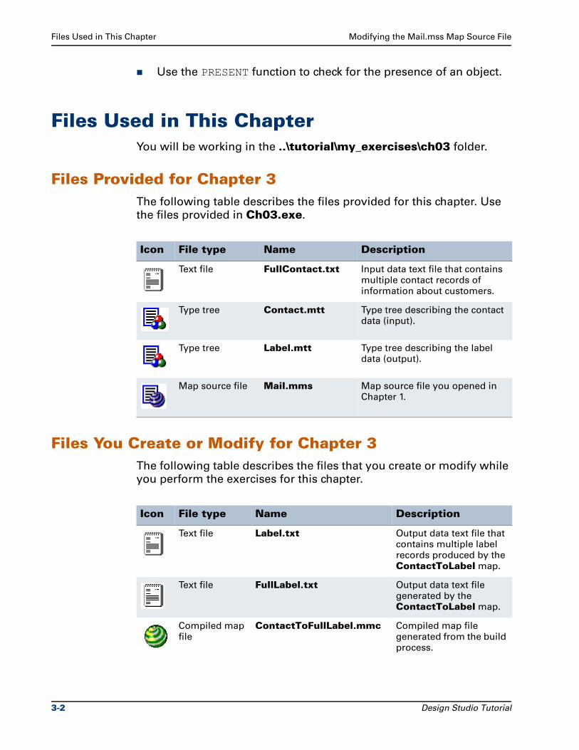
Files Used in This Chapter Modifying the Mail.mss Map Source File
Use the PRESENT function to check for the presence of an object.
Files Used in This ChapterYou will be working in the ..\tutorial\my_exercises\ch03 folder.
Files Provided for Chapter 3The following table describes the files provided for this chapter. Use
the files provided in Ch03.exe.
Files You Create or Modify for Chapter 3The following table describes the files that you create or modify while
you perform the exercises for this chapter.
Icon File type Name Description
Text file FullContact.txt Input data text file that contains multiple contact records of information about customers.
Type tree Contact.mtt Type tree describing the contact data (input).
Type tree Label.mtt Type tree describing the label data (output).
Map source file Mail.mms Map source file you opened in Chapter 1.
Icon File type Name Description
Text file Label.txt Output data text file that contains multiple label records produced by the ContactToLabel map.
Text file FullLabel.txt Output data text file generated by the ContactToLabel map.
Compiled map file
ContactToFullLabel.mmc Compiled map file generated from the build process.
3-2 Design Studio Tutorial
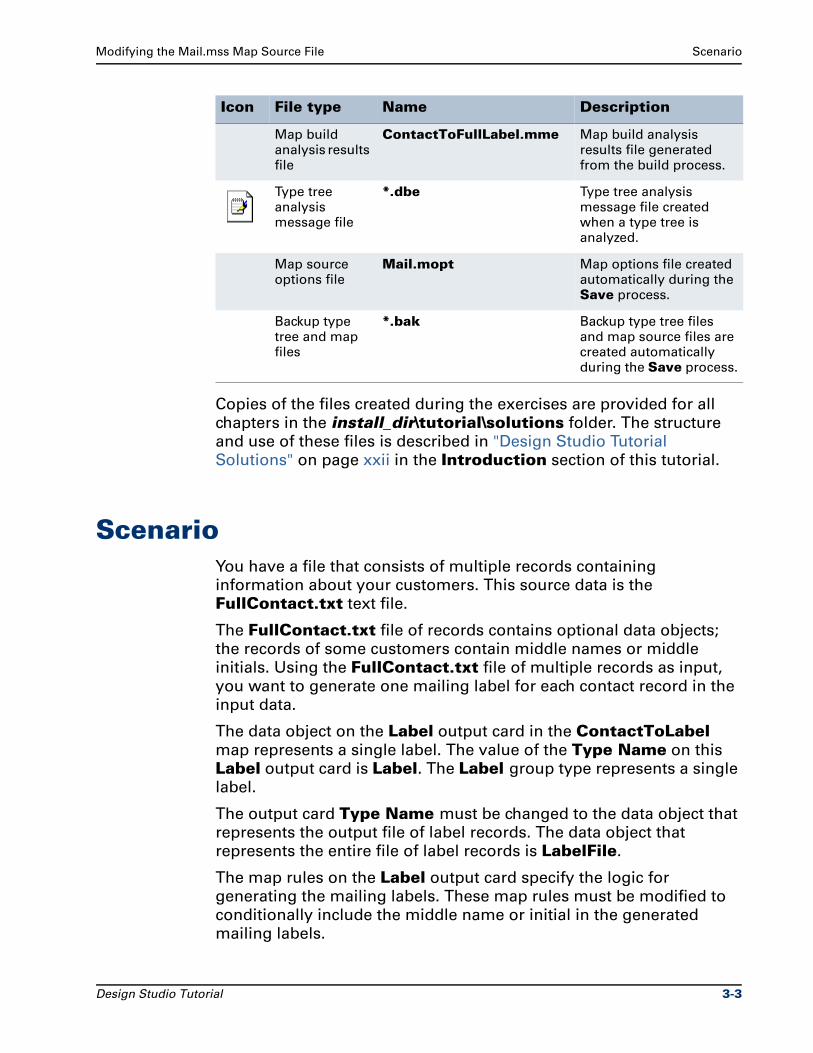
Modifying the Mail.mss Map Source File Scenario
Copies of the files created during the exercises are provided for all
chapters in the install_dir\tutorial\solutions folder. The structure
and use of these files is described in "Design Studio Tutorial
Solutions" on page xxii in the Introduction section of this tutorial.
ScenarioYou have a file that consists of multiple records containing
information about your customers. This source data is the
FullContact.txt text file.
The FullContact.txt file of records contains optional data objects;
the records of some customers contain middle names or middle
initials. Using the FullContact.txt file of multiple records as input,
you want to generate one mailing label for each contact record in the
input data.
The data object on the Label output card in the ContactToLabel map represents a single label. The value of the Type Name on this
Label output card is Label. The Label group type represents a single
label.
The output card Type Name must be changed to the data object that
represents the output file of label records. The data object that
represents the entire file of label records is LabelFile.
The map rules on the Label output card specify the logic for
generating the mailing labels. These map rules must be modified to
conditionally include the middle name or initial in the generated
mailing labels.
Map build analysis results file
ContactToFullLabel.mme Map build analysis results file generated from the build process.
Type tree analysis message file
*.dbe Type tree analysis message file created when a type tree is analyzed.
Map source options file
Mail.mopt Map options file created automatically during the Save process.
Backup type tree and map files
*.bak Backup type tree files and map source files are created automatically during the Save process.
Icon File type Name Description
Design Studio Tutorial 3-3
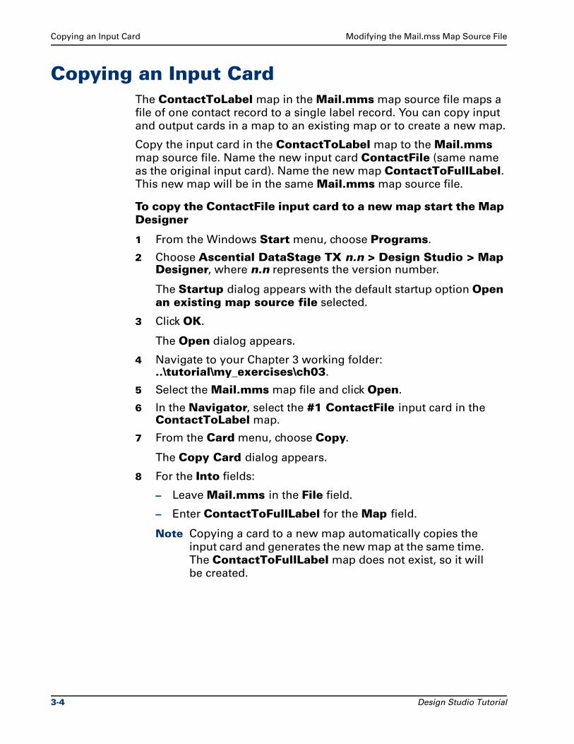
Copying an Input Card Modifying the Mail.mss Map Source File
Copying an Input CardThe ContactToLabel map in the Mail.mms map source file maps a
file of one contact record to a single label record. You can copy input
and output cards in a map to an existing map or to create a new map.
Copy the input card in the ContactToLabel map to the Mail.mms
map source file. Name the new input card ContactFile (same name
as the original input card). Name the new map ContactToFullLabel. This new map will be in the same Mail.mms map source file.
To copy the ContactFile input card to a new map start the Map Designer
1 From the Windows Start menu, choose Programs.
2 Choose Ascential DataStage TX n.n > Design Studio > Map Designer, where n.n represents the version number.
The Startup dialog appears with the default startup option Open an existing map source file selected.
3 Click OK.
The Open dialog appears.
4 Navigate to your Chapter 3 working folder: ..\tutorial\my_exercises\ch03.
5 Select the Mail.mms map file and click Open.
6 In the Navigator, select the #1 ContactFile input card in the ContactToLabel map.
7 From the Card menu, choose Copy.
The Copy Card dialog appears.
8 For the Into fields:
– Leave Mail.mms in the File field.
– Enter ContactToFullLabel for the Map field.
Note Copying a card to a new map automatically copies the
input card and generates the new map at the same time.
The ContactToFullLabel map does not exist, so it will
be created.
3-4 Design Studio Tutorial
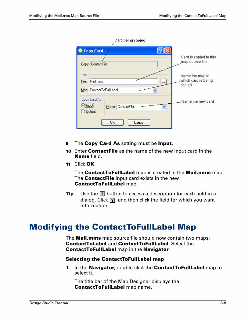
Modifying the Mail.mss Map Source File Modifying the ContactToFullLabel Map
9 The Copy Card As setting must be Input.
10 Enter ContactFile as the name of the new input card in the Name field.
11 Click OK.
The ContactToFullLabel map is created in the Mail.mms map.
The ContactFile input card exists in the new
ContactToFullLabel map.
Tip Use the button to access a description for each field in a
dialog. Click , and then click the field for which you want
information.
Modifying the ContactToFullLabel MapThe Mail.mms map source file should now contain two maps:
ContactToLabel and ContactToFullLabel. Select the
ContactToFullLabel map in the Navigator.
Selecting the ContactToFullLabel map
1 In the Navigator, double-click the ContactToFullLabel map to select it.
The title bar of the Map Designer displays the
ContactToFullLabel map name.
Design Studio Tutorial 3-5
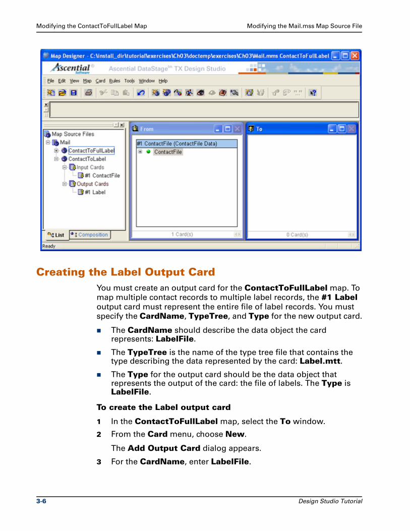
Modifying the ContactToFullLabel Map Modifying the Mail.mss Map Source File
Creating the Label Output CardYou must create an output card for the ContactToFullLabel map. To
map multiple contact records to multiple label records, the #1 Label output card must represent the entire file of label records. You must
specify the CardName, TypeTree, and Type for the new output card.
The CardName should describe the data object the card represents: LabelFile.
The TypeTree is the name of the type tree file that contains the type describing the data represented by the card: Label.mtt.
The Type for the output card should be the data object that represents the output of the card: the file of labels. The Type is LabelFile.
To create the Label output card
1 In the ContactToFullLabel map, select the To window.
2 From the Card menu, choose New.
The Add Output Card dialog appears.
3 For the CardName, enter LabelFile.
3-6 Design Studio Tutorial
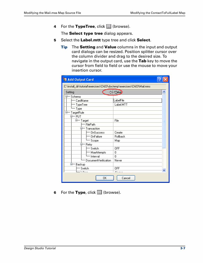
Modifying the Mail.mss Map Source File Modifying the ContactToFullLabel Map
4 For the TypeTree, click (browse).
The Select type tree dialog appears.
5 Select the Label.mtt type tree and click Select.
Tip The Setting and Value columns in the input and output
card dialogs can be resized. Position splitter cursor over
the column divider and drag to the desired size. To
navigate in the output card, use the Tab key to move the
cursor from field to field or use the mouse to move your
insertion cursor.
6 For the Type, click (browse).
Design Studio Tutorial 3-7
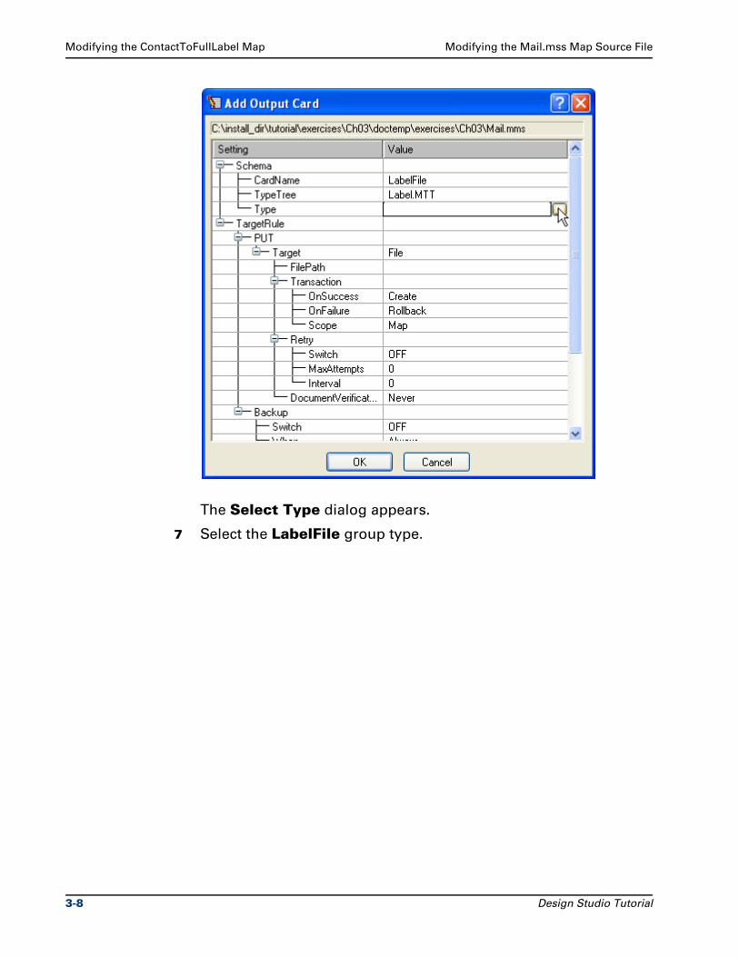
Modifying the ContactToFullLabel Map Modifying the Mail.mss Map Source File
The Select Type dialog appears.
7 Select the LabelFile group type.
3-8 Design Studio Tutorial
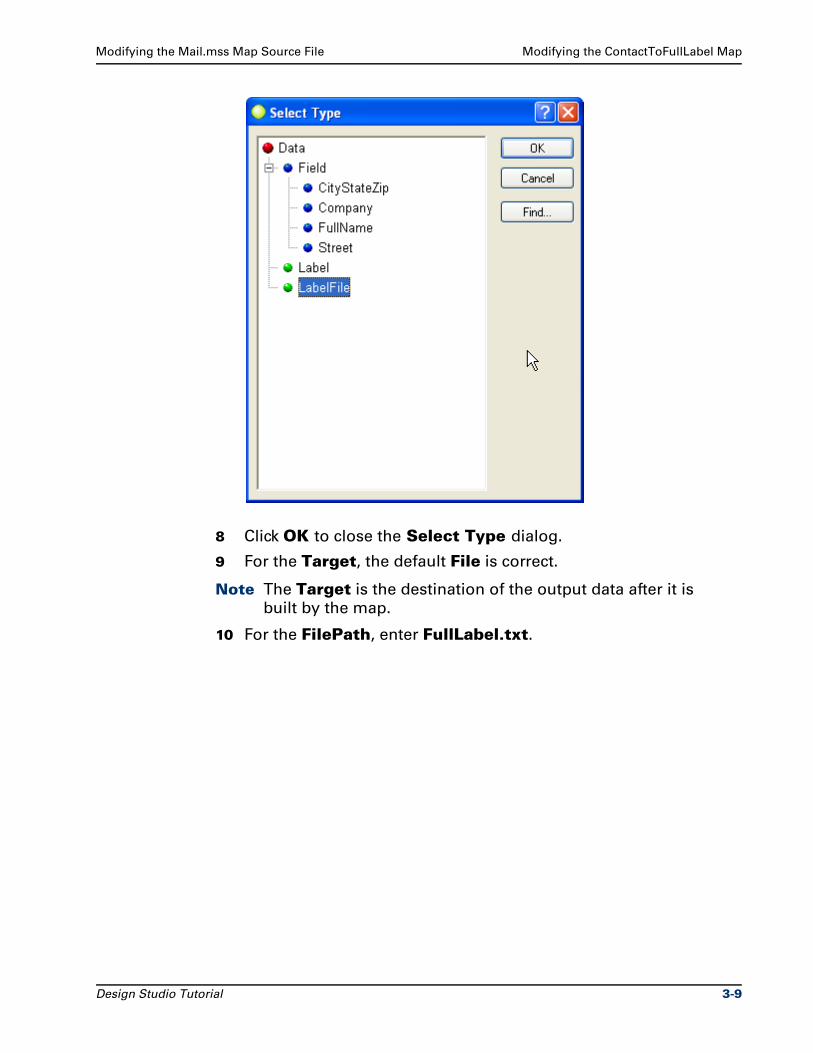
Modifying the Mail.mss Map Source File Modifying the ContactToFullLabel Map
8 Click OK to close the Select Type dialog.
9 For the Target, the default File is correct.
Note The Target is the destination of the output data after it is
built by the map.
10 For the FilePath, enter FullLabel.txt.
Design Studio Tutorial 3-9
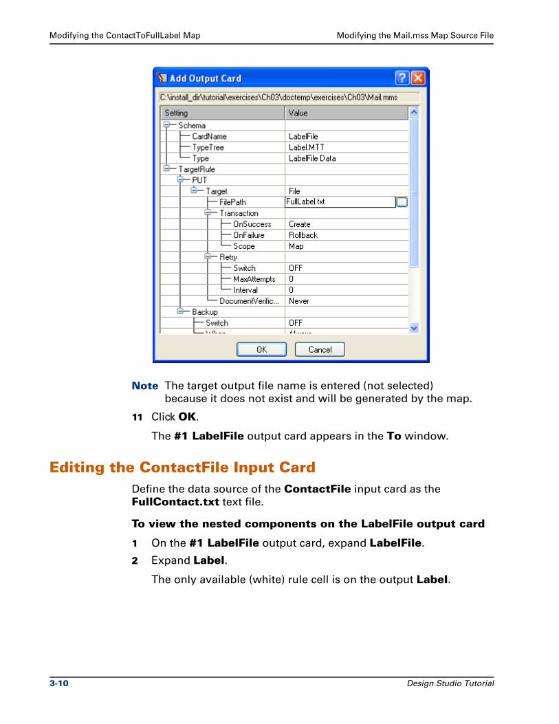
Modifying the ContactToFullLabel Map Modifying the Mail.mss Map Source File
Note The target output file name is entered (not selected)
because it does not exist and will be generated by the map.
11 Click OK.
The #1 LabelFile output card appears in the To window.
Editing the ContactFile Input CardDefine the data source of the ContactFile input card as the
FullContact.txt text file.
To view the nested components on the LabelFile output card
1 On the #1 LabelFile output card, expand LabelFile.
2 Expand Label.
The only available (white) rule cell is on the output Label.
3-10 Design Studio Tutorial
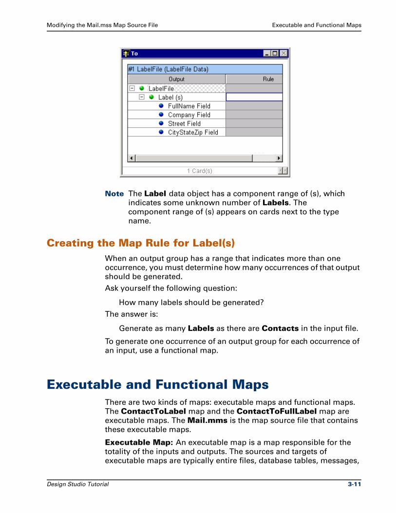
Modifying the Mail.mss Map Source File Executable and Functional Maps
Note The Label data object has a component range of (s), which
indicates some unknown number of Labels. The
component range of (s) appears on cards next to the type
name.
Creating the Map Rule for Label(s)When an output group has a range that indicates more than one
occurrence, you must determine how many occurrences of that output
should be generated.
Ask yourself the following question:
How many labels should be generated?
The answer is:
Generate as many Labels as there are Contacts in the input file.
To generate one occurrence of an output group for each occurrence of
an input, use a functional map.
Executable and Functional MapsThere are two kinds of maps: executable maps and functional maps.
The ContactToLabel map and the ContactToFullLabel map are
executable maps. The Mail.mms is the map source file that contains
these executable maps.
Executable Map: An executable map is a map responsible for the
totality of the inputs and outputs. The sources and targets of
executable maps are typically entire files, database tables, messages,
Design Studio Tutorial 3-11
Executable and Functional Maps Modifying the Mail.mss Map Source File
applications, and so on. Think of an executable map as the main map,
the top-level map. Executable maps are compiled and run.
In the Navigator, the icon for an executable map is blue .
Functional Map: A functional map is referenced by another map
through a map rule. A functional map maps just a portion of the entire
data. Data sources and targets are not specified in the input and
output cards of functional maps. Functional maps are not compiled
and run.
In the Navigator, the icon for a functional map (or an incomplete
executable map) is gray .
Functional MapsA functional map is like a sub-routine; it maps a portion of data at a
time. A functional map takes one or more input objects and generates
one output object.
The use of functional maps is very common. Almost every executable
map created will use at least one functional map. A functional map
and the executable map that calls it must be in the same map source
file (.mms).
To map a group in the input to a different group in the output, use a
functional map. The presence of an output component with a range of
more than one is one determining factor of when to use a functional
map.
Note The Label data object component range of (s) indicates the
number of Label(s) to be created is based on the number of
Contact(s).
Another important factor in determining when to use a functional map
is when you want to transform the data: mapping from one or more
types to a different type.
For the ContactToFullLabel map, we want to map from the First Name Field, Middle Name Field, and Last Name Field to the
FullName Field.
We know we need to use a functional map because:
The number of a certain output group, Label, that we want to create is based on the occurrences of some input data, Contact.
The types are different types (First Name Field, Middle Name Field, and Last Name Field to FullName Field).
3-12 Design Studio Tutorial
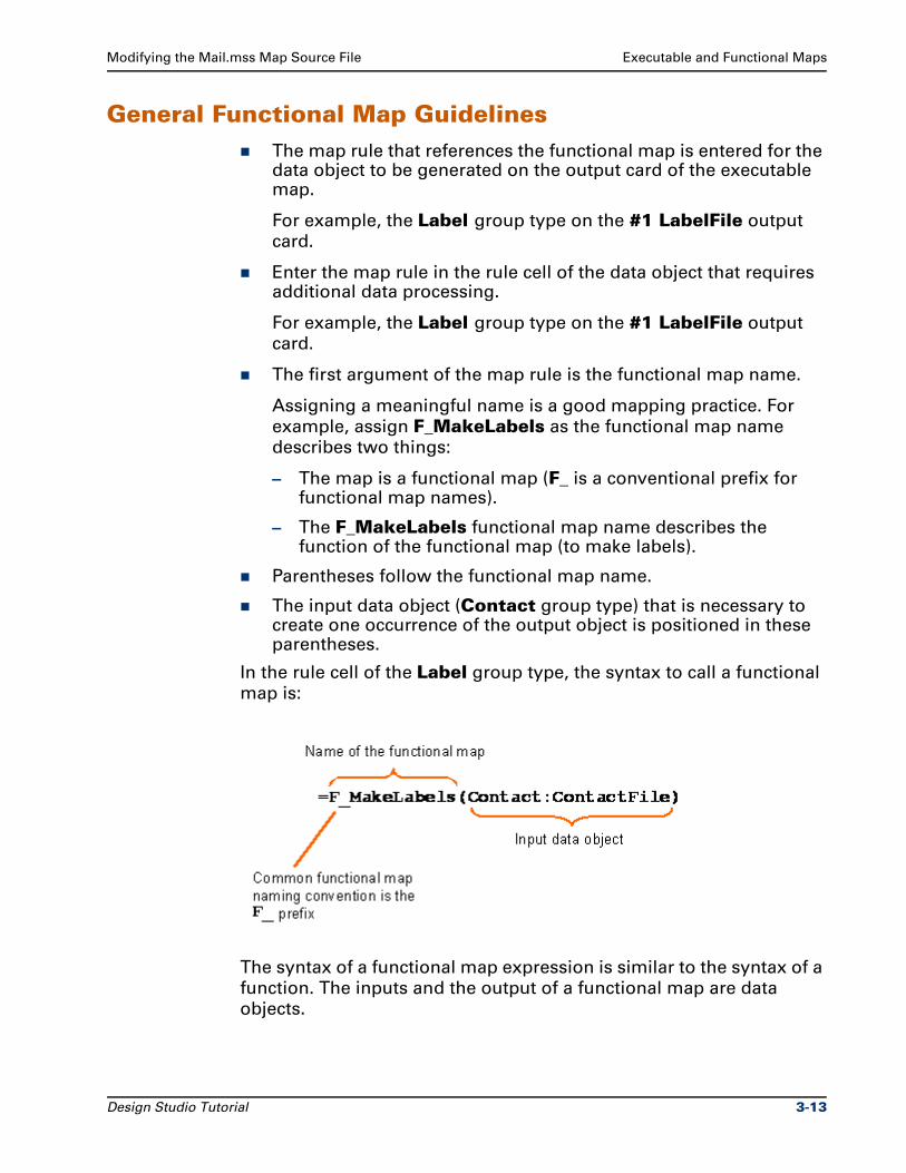
Modifying the Mail.mss Map Source File Executable and Functional Maps
General Functional Map GuidelinesThe map rule that references the functional map is entered for the data object to be generated on the output card of the executable map.
For example, the Label group type on the #1 LabelFile output
card.
Enter the map rule in the rule cell of the data object that requires additional data processing.
For example, the Label group type on the #1 LabelFile output
card.
The first argument of the map rule is the functional map name.
Assigning a meaningful name is a good mapping practice. For
example, assign F_MakeLabels as the functional map name
describes two things:
– The map is a functional map (F_ is a conventional prefix for functional map names).
– The F_MakeLabels functional map name describes the function of the functional map (to make labels).
Parentheses follow the functional map name.
The input data object (Contact group type) that is necessary to create one occurrence of the output object is positioned in these parentheses.
In the rule cell of the Label group type, the syntax to call a functional
map is:
The syntax of a functional map expression is similar to the syntax of a
function. The inputs and the output of a functional map are data
objects.
Design Studio Tutorial 3-13
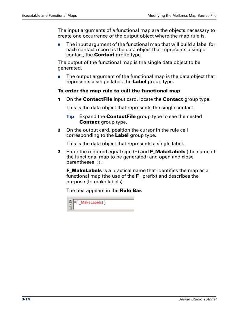
Executable and Functional Maps Modifying the Mail.mss Map Source File
The input arguments of a functional map are the objects necessary to
create one occurrence of the output object where the map rule is.
The input argument of the functional map that will build a label for each contact record is the data object that represents a single contact, the Contact group type.
The output of the functional map is the single data object to be
generated.
The output argument of the functional map is the data object that represents a single label, the Label group type.
To enter the map rule to call the functional map
1 On the ContactFile input card, locate the Contact group type.
This is the data object that represents the single contact.
Tip Expand the ContactFile group type to see the nested
Contact group type.
2 On the output card, position the cursor in the rule cell corresponding to the Label group type.
This is the data object that represents a single label.
3 Enter the required equal sign (=) and F_MakeLabels (the name of the functional map to be generated) and open and close parentheses ().
F_MakeLabels is a practical name that identifies the map as a
functional map (the use of the F_ prefix) and describes the
purpose (to make labels).
The text appears in the Rule Bar.
3-14 Design Studio Tutorial
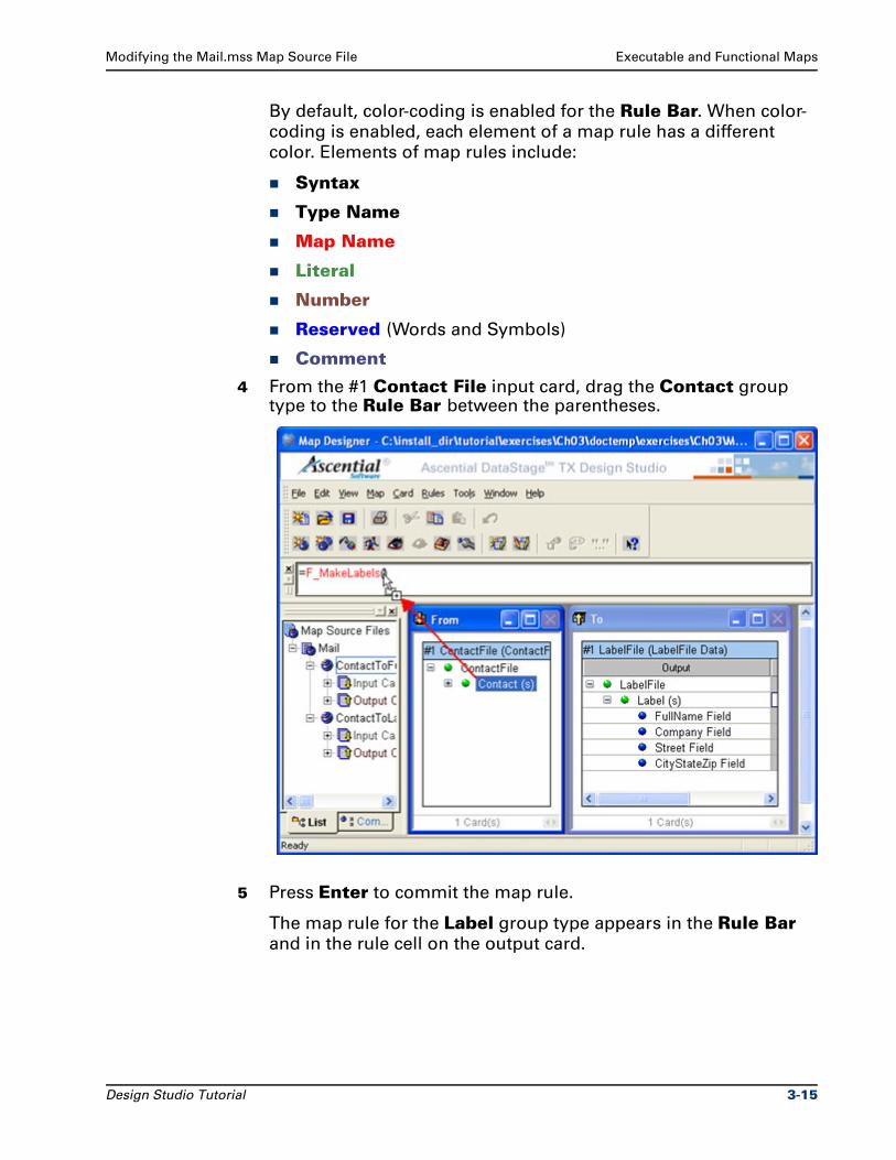
Modifying the Mail.mss Map Source File Executable and Functional Maps
By default, color-coding is enabled for the Rule Bar. When color-
coding is enabled, each element of a map rule has a different
color. Elements of map rules include:
Syntax
Type Name
Map Name
Literal
Number
Reserved (Words and Symbols)
Comment
4 From the #1 Contact File input card, drag the Contact group type to the Rule Bar between the parentheses.
5 Press Enter to commit the map rule.
The map rule for the Label group type appears in the Rule Bar
and in the rule cell on the output card.
Design Studio Tutorial 3-15
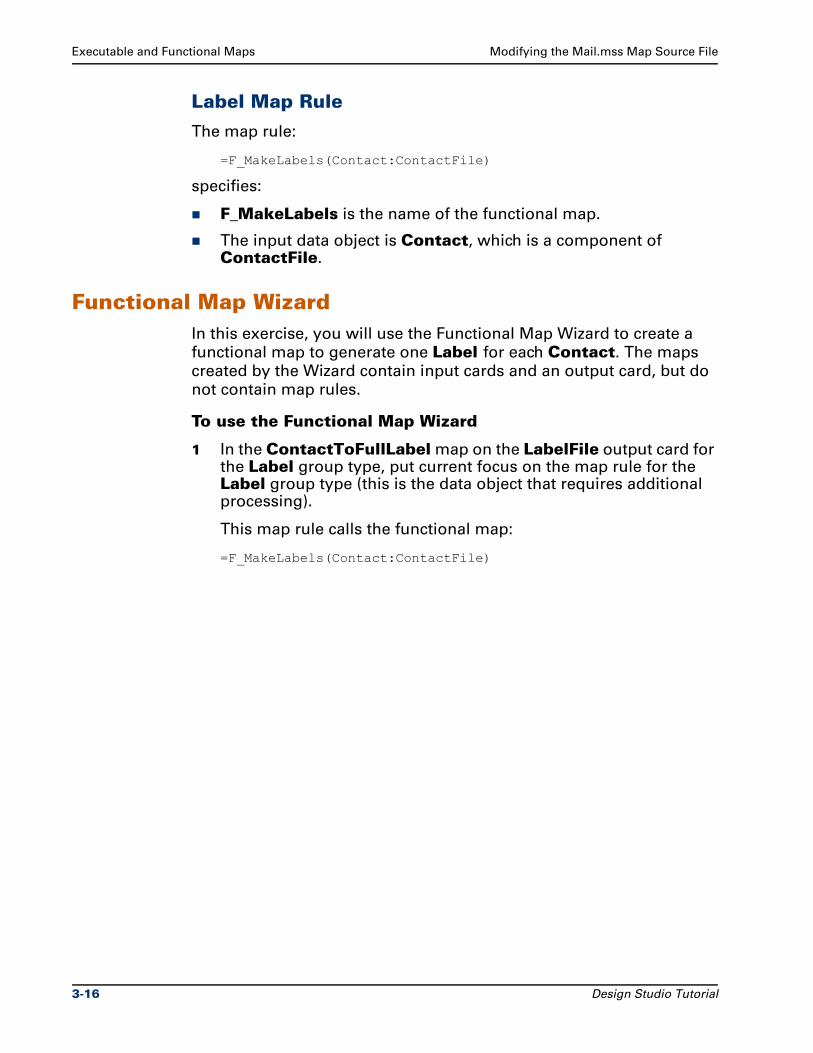
Executable and Functional Maps Modifying the Mail.mss Map Source File
Label Map Rule
The map rule:
=F_MakeLabels(Contact:ContactFile)
specifies:
F_MakeLabels is the name of the functional map.
The input data object is Contact, which is a component of ContactFile.
Functional Map WizardIn this exercise, you will use the Functional Map Wizard to create a
functional map to generate one Label for each Contact. The maps
created by the Wizard contain input cards and an output card, but do
not contain map rules.
To use the Functional Map Wizard
1 In the ContactToFullLabel map on the LabelFile output card for the Label group type, put current focus on the map rule for the Label group type (this is the data object that requires additional processing).
This map rule calls the functional map:
=F_MakeLabels(Contact:ContactFile)
3-16 Design Studio Tutorial
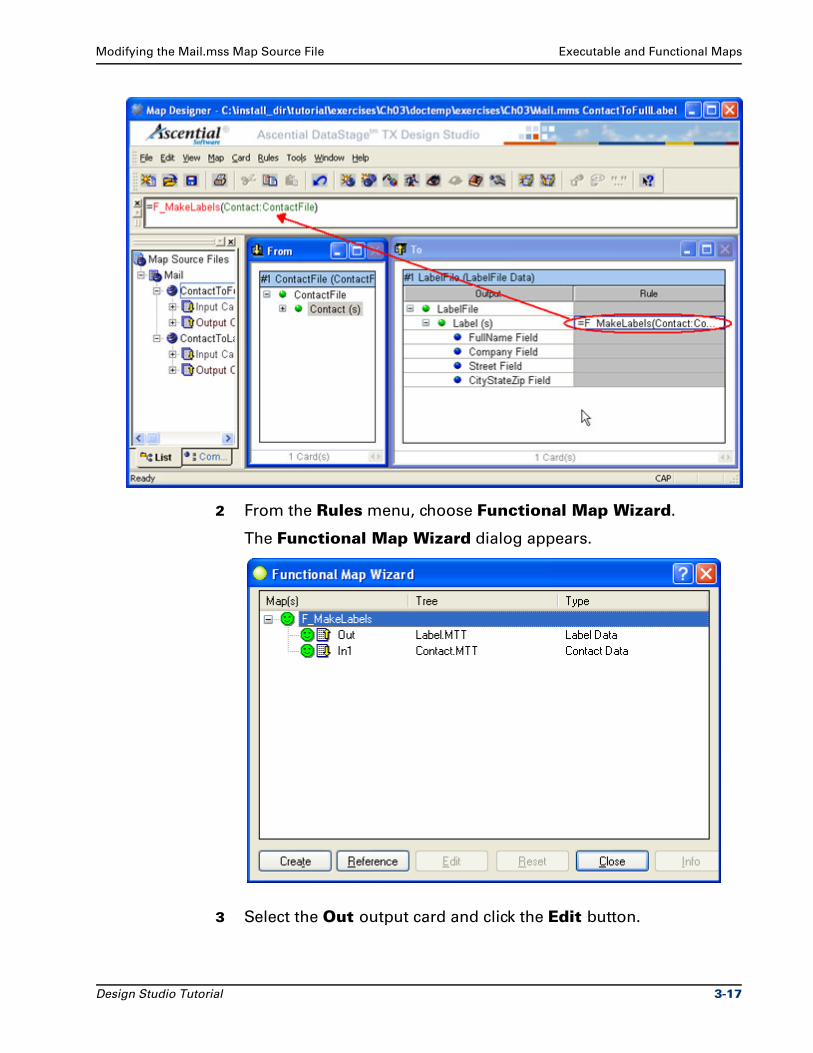
Modifying the Mail.mss Map Source File Executable and Functional Maps
2 From the Rules menu, choose Functional Map Wizard.
The Functional Map Wizard dialog appears.
3 Select the Out output card and click the Edit button.
Design Studio Tutorial 3-17
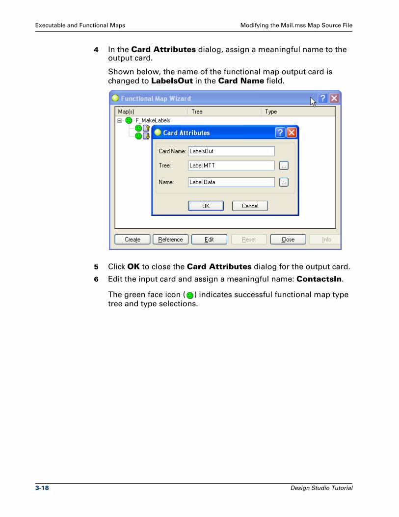
Executable and Functional Maps Modifying the Mail.mss Map Source File
4 In the Card Attributes dialog, assign a meaningful name to the output card.
Shown below, the name of the functional map output card is
changed to LabelsOut in the Card Name field.
5 Click OK to close the Card Attributes dialog for the output card.
6 Edit the input card and assign a meaningful name: ContactsIn.
The green face icon ( ) indicates successful functional map type
tree and type selections.
3-18 Design Studio Tutorial
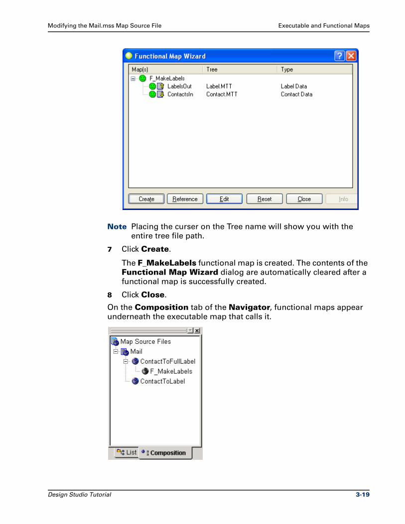
Modifying the Mail.mss Map Source File Executable and Functional Maps
Note Placing the curser on the Tree name will show you with the
entire tree file path.
7 Click Create.
The F_MakeLabels functional map is created. The contents of the
Functional Map Wizard dialog are automatically cleared after a
functional map is successfully created.
8 Click Close.
On the Composition tab of the Navigator, functional maps appear
underneath the executable map that calls it.
Design Studio Tutorial 3-19
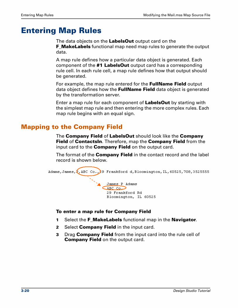
Entering Map Rules Modifying the Mail.mss Map Source File
Entering Map RulesThe data objects on the LabelsOut output card on the
F_MakeLabels functional map need map rules to generate the output
data.
A map rule defines how a particular data object is generated. Each
component of the #1 LabelsOut output card has a corresponding
rule cell. In each rule cell, a map rule defines how that output should
be generated.
For example, the map rule entered for the FullName Field output
data object defines how the FullName Field data object is generated
by the transformation server.
Enter a map rule for each component of LabelsOut by starting with
the simplest map rule and then entering the more complex rules. Each
map rule begins with an equal sign.
Mapping to the Company FieldThe Company Field of LabelsOut should look like the Company Field of ContactsIn. Therefore, map the Company Field from the
input card to the Company Field on the output card.
The format of the Company Field in the contact record and the label
record is shown below.
To enter a map rule for Company Field
1 Select the F_MakeLabels functional map in the Navigator.
2 Select Company Field in the input card.
3 Drag Company Field from the input card into the rule cell of Company Field on the output card.
3-20 Design Studio Tutorial
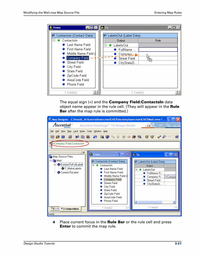
Modifying the Mail.mss Map Source File Entering Map Rules
The equal sign (=) and the Company Field:ContactsIn data
object name appear in the rule cell. (They will appear in the Rule Bar after the map rule is committed.)
4 Place current focus in the Rule Bar or the rule cell and press Enter to commit the map rule.
Design Studio Tutorial 3-21
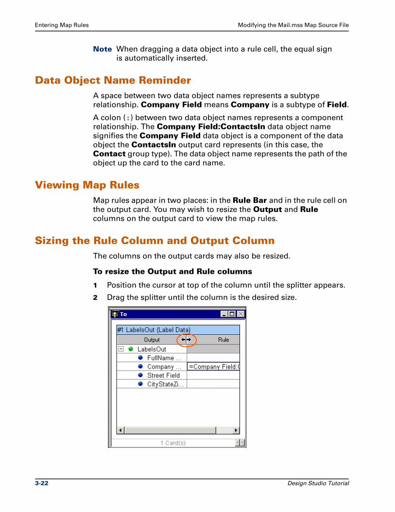
Entering Map Rules Modifying the Mail.mss Map Source File
Note When dragging a data object into a rule cell, the equal sign
is automatically inserted.
Data Object Name ReminderA space between two data object names represents a subtype
relationship. Company Field means Company is a subtype of Field.
A colon (:) between two data object names represents a component
relationship. The Company Field:ContactsIn data object name
signifies the Company Field data object is a component of the data
object the ContactsIn output card represents (in this case, the
Contact group type). The data object name represents the path of the
object up the card to the card name.
Viewing Map RulesMap rules appear in two places: in the Rule Bar and in the rule cell on
the output card. You may wish to resize the Output and Rule
columns on the output card to view the map rules.
Sizing the Rule Column and Output ColumnThe columns on the output cards may also be resized.
To resize the Output and Rule columns
1 Position the cursor at top of the column until the splitter appears.
2 Drag the splitter until the column is the desired size.
3-22 Design Studio Tutorial
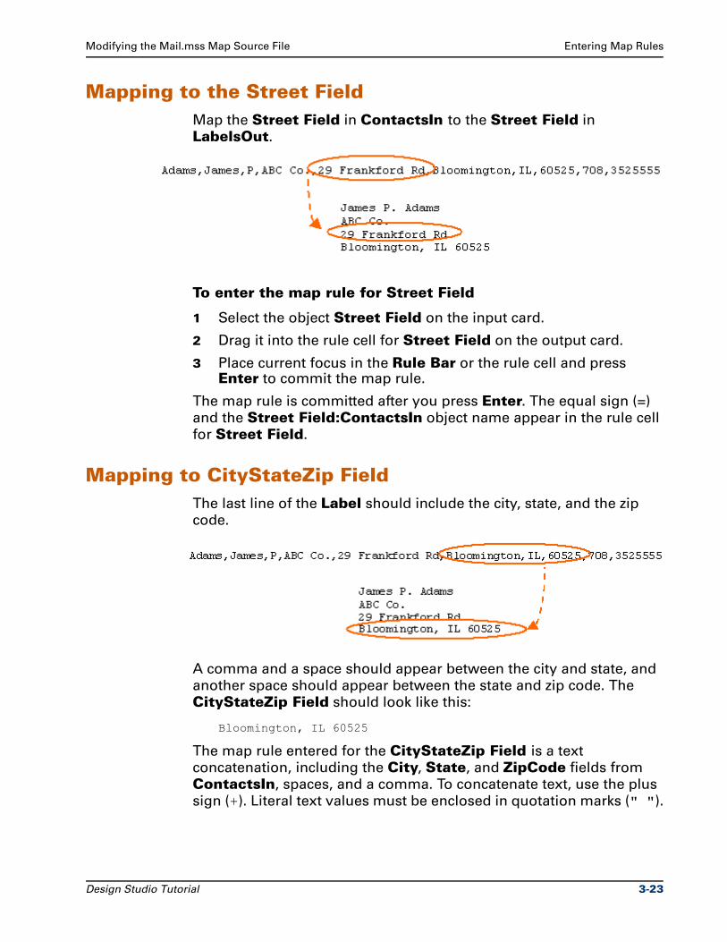
Modifying the Mail.mss Map Source File Entering Map Rules
Mapping to the Street FieldMap the Street Field in ContactsIn to the Street Field in
LabelsOut.
To enter the map rule for Street Field
1 Select the object Street Field on the input card.
2 Drag it into the rule cell for Street Field on the output card.
3 Place current focus in the Rule Bar or the rule cell and press Enter to commit the map rule.
The map rule is committed after you press Enter. The equal sign (=)
and the Street Field:ContactsIn object name appear in the rule cell
for Street Field.
Mapping to CityStateZip FieldThe last line of the Label should include the city, state, and the zip
code.
A comma and a space should appear between the city and state, and
another space should appear between the state and zip code. The
CityStateZip Field should look like this:
Bloomington, IL 60525
The map rule entered for the CityStateZip Field is a text
concatenation, including the City, State, and ZipCode fields from
ContactsIn, spaces, and a comma. To concatenate text, use the plus
sign (+). Literal text values must be enclosed in quotation marks (" ").
Design Studio Tutorial 3-23
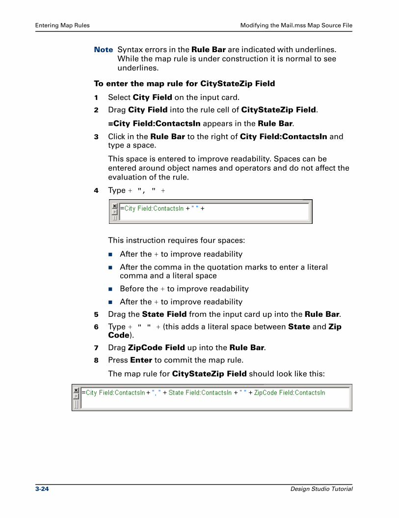
Entering Map Rules Modifying the Mail.mss Map Source File
Note Syntax errors in the Rule Bar are indicated with underlines.
While the map rule is under construction it is normal to see
underlines.
To enter the map rule for CityStateZip Field
1 Select City Field on the input card.
2 Drag City Field into the rule cell of CityStateZip Field.
=City Field:ContactsIn appears in the Rule Bar.
3 Click in the Rule Bar to the right of City Field:ContactsIn and type a space.
This space is entered to improve readability. Spaces can be
entered around object names and operators and do not affect the
evaluation of the rule.
4 Type + ", " +
This instruction requires four spaces:
After the + to improve readability
After the comma in the quotation marks to enter a literal comma and a literal space
Before the + to improve readability
After the + to improve readability
5 Drag the State Field from the input card up into the Rule Bar.
6 Type + " " + (this adds a literal space between State and Zip Code).
7 Drag ZipCode Field up into the Rule Bar.
8 Press Enter to commit the map rule.
The map rule for CityStateZip Field should look like this:
3-24 Design Studio Tutorial
Modifying the Mail.mss Map Source File Entering Map Rules
Mapping to the FullName FieldMap the First, Middle, and Last Name Fields from the ContactsIn
input card to the FullName Field in the LabelsOut output card.
Remember that the Middle Name Field is optional and does not
have to appear in the data. If the contact record does not have a
middle name, the Middle Name Field should not be mapped.
Use a map rule that verifies that Middle Name Field is present. If
Middle Name Field is present, map it to the Full Name Field. If
Middle Name Field is not present, do not map it.
Functions Used in Map Rule
This map rule uses two functions:
PRESENT
IF
All functions are documented in detail in the Ascential DataStage TX
Help and the Functions and Expressions Reference Guide. The
functions must be used with the proper command syntax notation, as
described in "Conventions" on page iv.
PRESENT Function
The PRESENT function checks for the presence of an object. If the
object is present, the function returns TRUE. If the object is not
present, the function returns FALSE. The syntax of the PRESENT
function is:
PRESENT (object_to_look_for)
IF Function
This function evaluates a conditional expression, returning one value
if true, another if false.
There are three arguments in the IF function. The first argument is a
condition. If it is TRUE, the second argument is performed. If it is
FALSE, the third argument is performed. The syntax of the IF function
is:
IF (test_this, result_if_true [, result_if_false])
Another way to express the IF function syntax would be:
IF (condition, do this if the condition is met [, optionallydo this if the condition is not met])
Design Studio Tutorial 3-25
Entering Map Rules Modifying the Mail.mss Map Source File
The braces that surround the third argument [, result_if_false]
indicate that the comma and the third argument are optional.
Mapping the FullName FieldA description of the map rule is: "If the Middle Name Field is
present, map the First, Middle, and Last Name Fields. If the Middle Name Field is not present, map only the First and Last Name Fields."
The outer function in the map rule is the IF function.
The first argument of the IF function is the PRESENT function. The PRESENT function performs the test of a condition.
The second argument of the IF function is the text concatenation of the first, middle and last name: what to map if the condition is true.
The third argument for the IF function is a text concatenation of the first and last name (excluding the middle name) what to map if the condition is false.
The rule entered looks like this:
=IF (PRESENT (Middle Name Field:ContactsIn),
First Name Field:ContactsIn + " " + Middle Name Field:ContactsIn+ " " + Last Name Field:ContactsIn,
First Name Field:ContactsIn + " " + Last Name Field:ContactsIn)
To enter the map rule for Full Name Field
1 Select the rule cell next to FullName Field.
2 From the Rules menu, choose Insert Function.
The Insert Function dialog appears.
3 Select the IF function in the Functions list.
3-26 Design Studio Tutorial
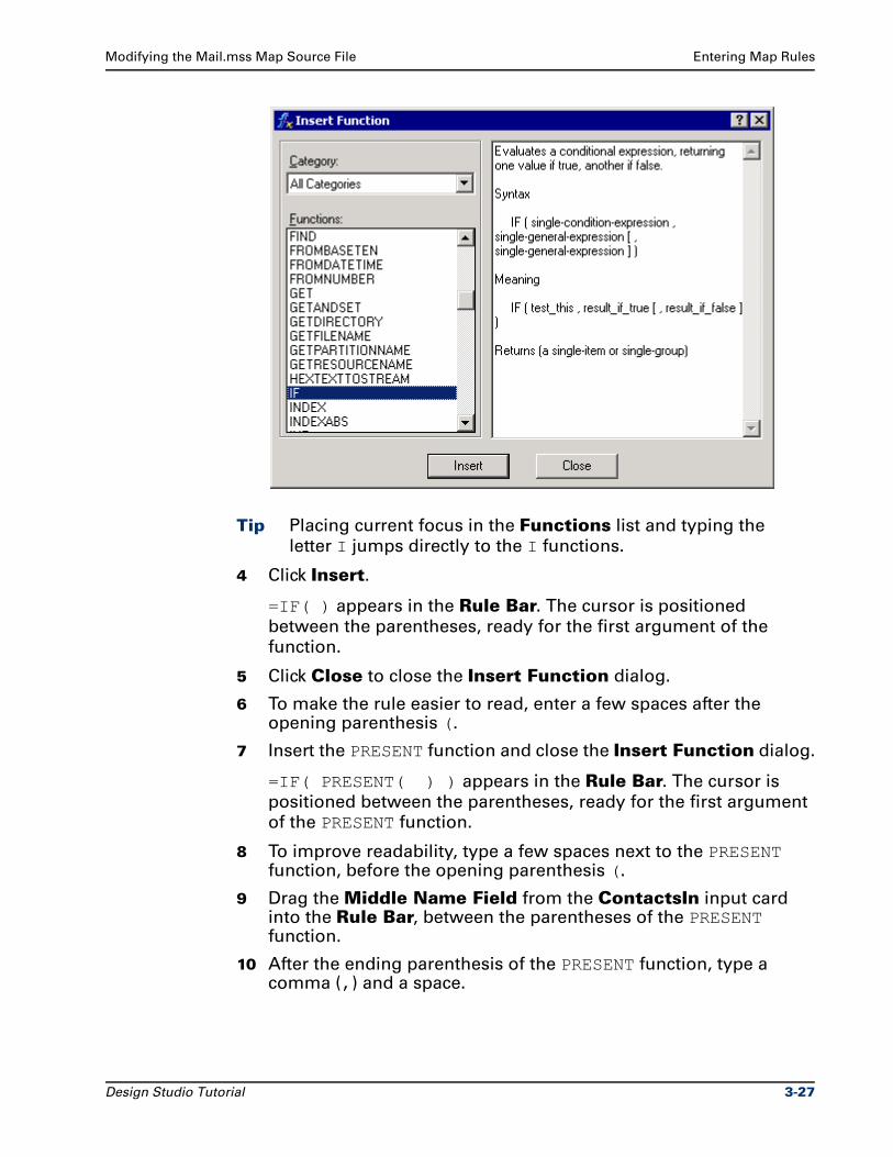
Modifying the Mail.mss Map Source File Entering Map Rules
Tip Placing current focus in the Functions list and typing the
letter I jumps directly to the I functions.
4 Click Insert.
=IF( ) appears in the Rule Bar. The cursor is positioned
between the parentheses, ready for the first argument of the
function.
5 Click Close to close the Insert Function dialog.
6 To make the rule easier to read, enter a few spaces after the opening parenthesis (.
7 Insert the PRESENT function and close the Insert Function dialog.
=IF( PRESENT( ) ) appears in the Rule Bar. The cursor is
positioned between the parentheses, ready for the first argument
of the PRESENT function.
8 To improve readability, type a few spaces next to the PRESENT function, before the opening parenthesis (.
9 Drag the Middle Name Field from the ContactsIn input card into the Rule Bar, between the parentheses of the PRESENT function.
10 After the ending parenthesis of the PRESENT function, type a comma (,) and a space.
Design Studio Tutorial 3-27
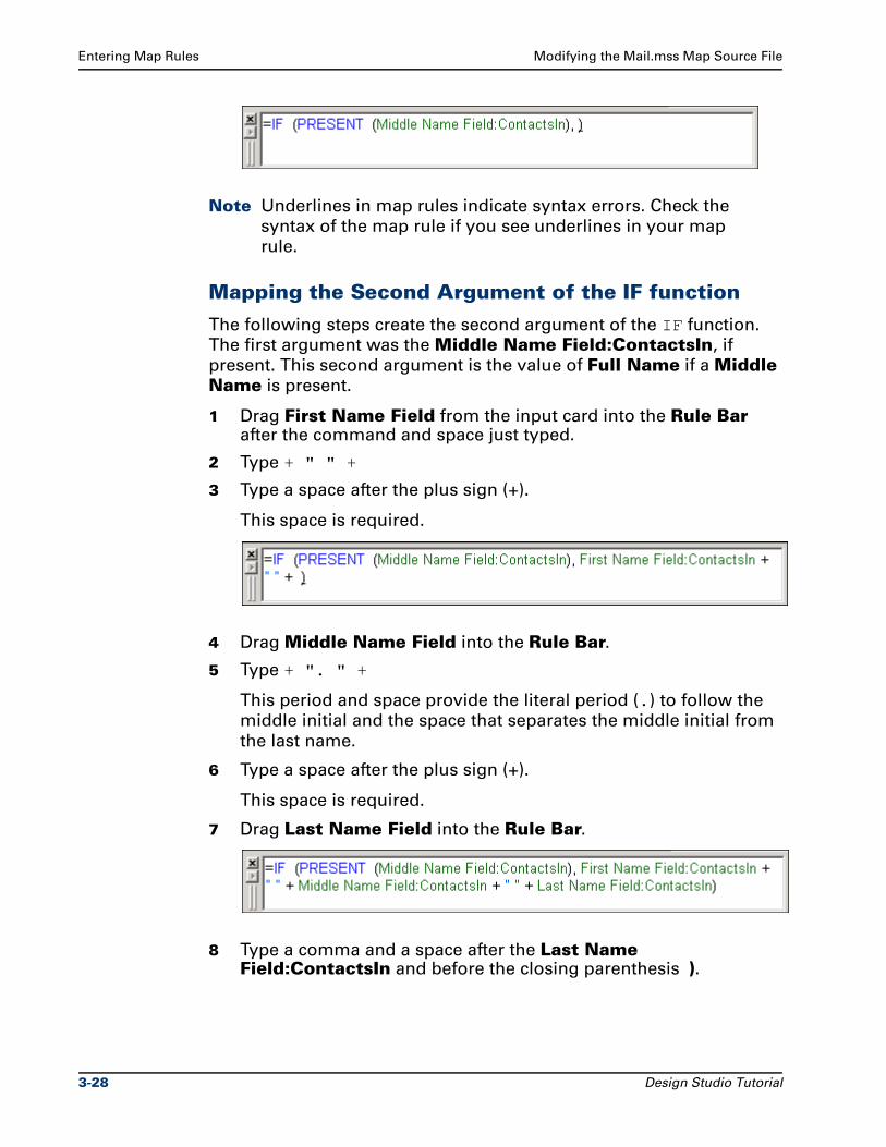
Entering Map Rules Modifying the Mail.mss Map Source File
Note Underlines in map rules indicate syntax errors. Check the
syntax of the map rule if you see underlines in your map
rule.
Mapping the Second Argument of the IF function
The following steps create the second argument of the IF function.
The first argument was the Middle Name Field:ContactsIn, if
present. This second argument is the value of Full Name if a Middle Name is present.
1 Drag First Name Field from the input card into the Rule Bar after the command and space just typed.
2 Type + " " +
3 Type a space after the plus sign (+).
This space is required.
4 Drag Middle Name Field into the Rule Bar.
5 Type + ". " +
This period and space provide the literal period (.) to follow the
middle initial and the space that separates the middle initial from
the last name.
6 Type a space after the plus sign (+).
This space is required.
7 Drag Last Name Field into the Rule Bar.
8 Type a comma and a space after the Last Name Field:ContactsIn and before the closing parenthesis ).
3-28 Design Studio Tutorial
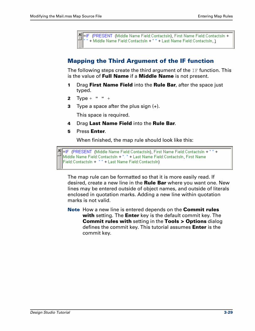
Modifying the Mail.mss Map Source File Entering Map Rules
Mapping the Third Argument of the IF function
The following steps create the third argument of the IF function. This
is the value of Full Name if a Middle Name is not present.
1 Drag First Name Field into the Rule Bar, after the space just typed.
2 Type + " " +
3 Type a space after the plus sign (+).
This space is required.
4 Drag Last Name Field into the Rule Bar.
5 Press Enter.
When finished, the map rule should look like this:
The map rule can be formatted so that it is more easily read. If
desired, create a new line in the Rule Bar where you want one. New
lines may be entered outside of object names, and outside of literals
enclosed in quotation marks. Adding a new line within quotation
marks is not valid.
Note How a new line is entered depends on the Commit rules with setting. The Enter key is the default commit key. The
Commit rules with setting in the Tools > Options dialog
defines the commit key. This tutorial assumes Enter is the
commit key.
Design Studio Tutorial 3-29
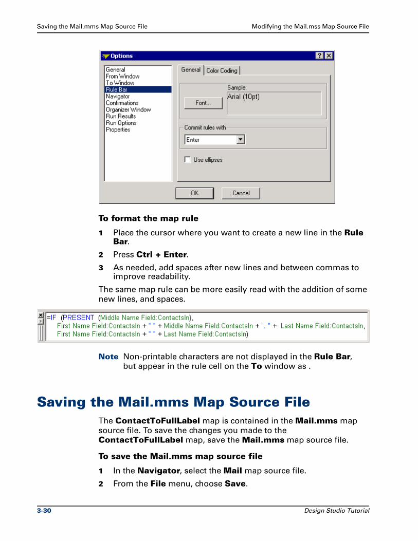
Saving the Mail.mms Map Source File Modifying the Mail.mss Map Source File
To format the map rule
1 Place the cursor where you want to create a new line in the Rule Bar.
2 Press Ctrl + Enter.
3 As needed, add spaces after new lines and between commas to improve readability.
The same map rule can be more easily read with the addition of some
new lines, and spaces.
Note Non-printable characters are not displayed in the Rule Bar, but appear in the rule cell on the To window as .
Saving the Mail.mms Map Source FileThe ContactToFullLabel map is contained in the Mail.mms map
source file. To save the changes you made to the
ContactToFullLabel map, save the Mail.mms map source file.
To save the Mail.mms map source file
1 In the Navigator, select the Mail map source file.
2 From the File menu, choose Save.
3-30 Design Studio Tutorial
Modifying the Mail.mss Map Source File Building the ContactToFullLabel Map
Building the ContactToFullLabel MapAfter the map rules are entered, the map can be built. During the map
build process, map rules are analyzed. If no errors occur, the map is
compiled and the .mmc compiled map file is created in the directory
where the map source file is located.
To build the ContactToFullLabel map
1 In the Navigator, select the ContactToFullLabel map.
2 From the Map menu, choose Build.
The message Building a map appears briefly in a message box,
which closes automatically.
If build errors occur the Organizer window appears automatically.
For help in resolving errors, see the Map Designer Reference Guide.
To view map build errors
1 In the Organizer window, click the Build Results tab.
2 Fix the errors, if any.
3 Build the map again.
Running the ContactToFullLabel MapAfter the map is built, the map can be run.
To run the ContactToFullLabel map
1 In the Navigator, select the ContactToFullLabel map.
2 From the Map menu, choose Run.
The Command Server window appears.
The Command Server window shows the map execution
progress, the total number of input objects found (3841 contact
record fields), and the total number of output objects built (1801
labels).
Design Studio Tutorial 3-31
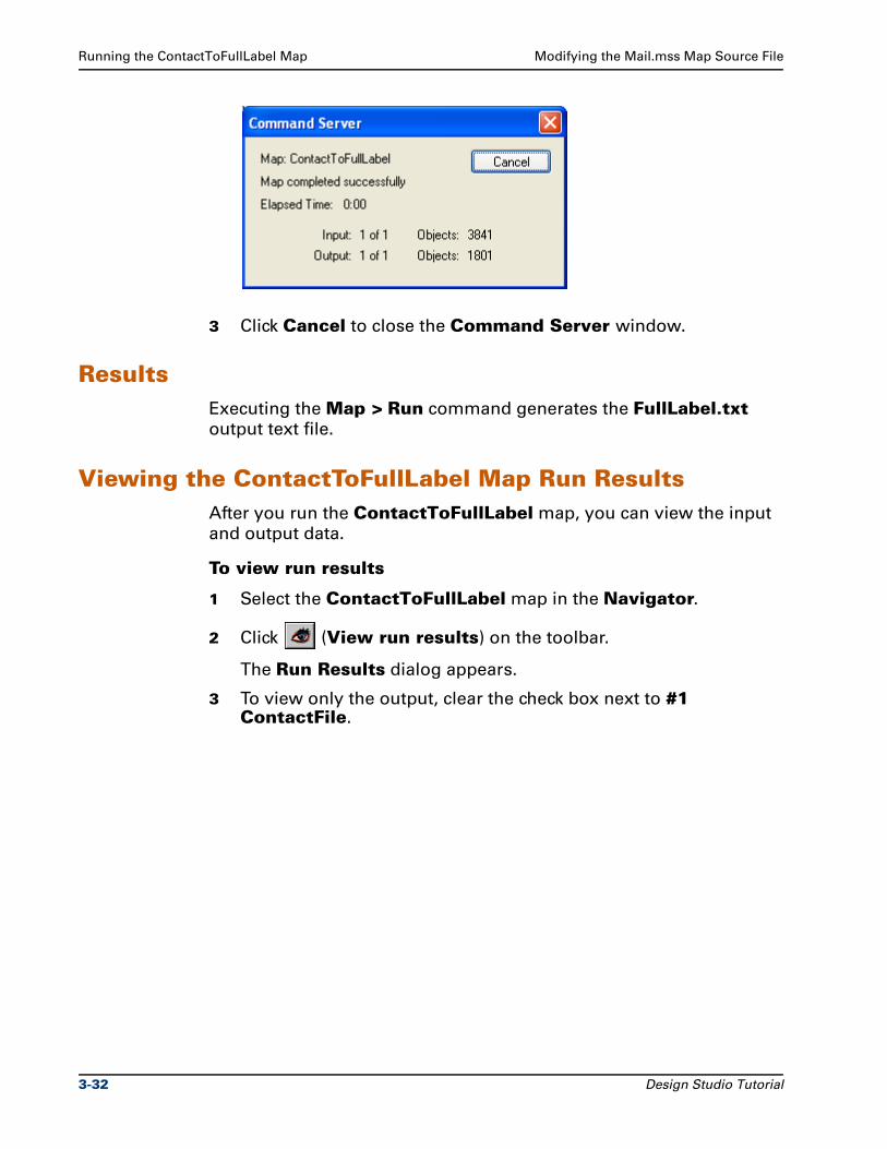
Running the ContactToFullLabel Map Modifying the Mail.mss Map Source File
3 Click Cancel to close the Command Server window.
ResultsExecuting the Map > Run command generates the FullLabel.txt
output text file.
Viewing the ContactToFullLabel Map Run ResultsAfter you run the ContactToFullLabel map, you can view the input
and output data.
To view run results
1 Select the ContactToFullLabel map in the Navigator.
2 Click (View run results) on the toolbar.
The Run Results dialog appears.
3 To view only the output, clear the check box next to #1 ContactFile.
3-32 Design Studio Tutorial
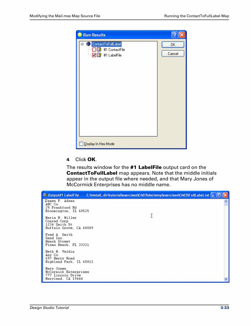
Modifying the Mail.mss Map Source File Running the ContactToFullLabel Map
4 Click OK.
The results window for the #1 LabelFile output card on the
ContactToFullLabel map appears. Note that the middle initials
appear in the output file where needed, and that Mary Jones of
McCormick Enterprises has no middle name.
Design Studio Tutorial 3-33
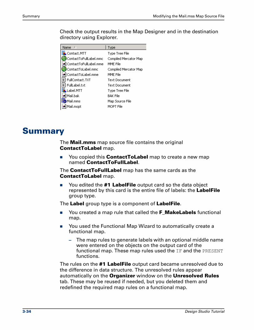
Summary Modifying the Mail.mss Map Source File
Check the output results in the Map Designer and in the destination
directory using Explorer.
SummaryThe Mail.mms map source file contains the original
ContactToLabel map.
You copied this ContactToLabel map to create a new map named ContactToFullLabel.
The ContactToFullLabel map has the same cards as the
ContactToLabel map.
You edited the #1 LabelFile output card so the data object represented by this card is the entire file of labels: the LabelFile group type.
The Label group type is a component of LabelFile.
You created a map rule that called the F_MakeLabels functional map.
You used the Functional Map Wizard to automatically create a functional map.
– The map rules to generate labels with an optional middle name were entered on the objects on the output card of the functional map. These map rules used the IF and the PRESENT functions.
The rules on the #1 LabelFile output card became unresolved due to
the difference in data structure. The unresolved rules appear
automatically on the Organizer window on the Unresolved Rules
tab. These may be reused if needed, but you deleted them and
redefined the required map rules on a functional map.
3-34 Design Studio Tutorial
Modifying the Mail.mss Map Source File Summary
The ContactToFullLabel specifies FullContact.txt as the data
source, and generates the Label.txt output file. Optionally, the
ContactToFullLabel output card was edited to generate the
FullLabel.txt output file.
The ContactToFullLabel map was saved, built, and run.
The results of the map were viewed.
Design Studio Tutorial 3-35

Summary Modifying the Mail.mss Map Source File
3-36 Design Studio Tutorial
4Using the UNIQUE Function
The ContactToFullLabel map created in Chapter 3 maps a file of
multiple contact records to a file of multiple labels. After analyzing the
output, it is clear that some of the contact records in the address file
occur multiple times.
ObjectivesThis exercise copies and modifies an existing map, and introduces the
UNIQUE function.
By completing the exercises for Chapter 4, you will learn how to:
Modify an existing map.
Copy an input card to create a new map.
Copy an input card to an output card.
Edit card settings.
Use the UNIQUE function to avoid creating duplicate records.
Files Used in This ChapterYou will be working in the ..\tutorial\my_exercises\ch04 folder.
Design Studio Tutorial 4-1
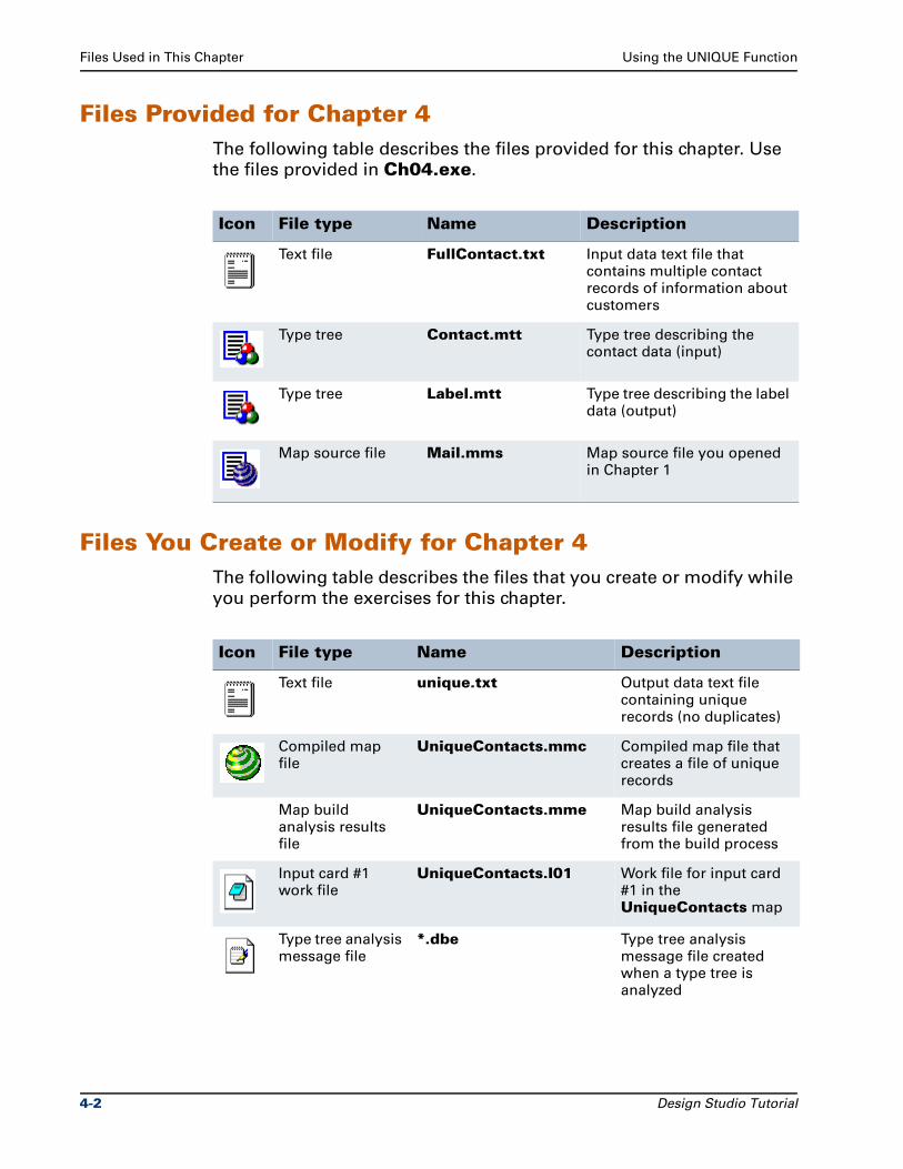
Files Used in This Chapter Using the UNIQUE Function
Files Provided for Chapter 4The following table describes the files provided for this chapter. Use
the files provided in Ch04.exe.
Files You Create or Modify for Chapter 4The following table describes the files that you create or modify while
you perform the exercises for this chapter.
Icon File type Name Description
Text file FullContact.txt Input data text file that contains multiple contact records of information about customers
Type tree Contact.mtt Type tree describing the contact data (input)
Type tree Label.mtt Type tree describing the label data (output)
Map source file Mail.mms Map source file you opened in Chapter 1
Icon File type Name Description
Text file unique.txt Output data text file containing unique records (no duplicates)
Compiled map file
UniqueContacts.mmc Compiled map file that creates a file of unique records
Map build analysis results file
UniqueContacts.mme Map build analysis results file generated from the build process
Input card #1 work file
UniqueContacts.I01 Work file for input card #1 in the UniqueContacts map
Type tree analysis message file
*.dbe Type tree analysis message file created when a type tree is analyzed
4-2 Design Studio Tutorial
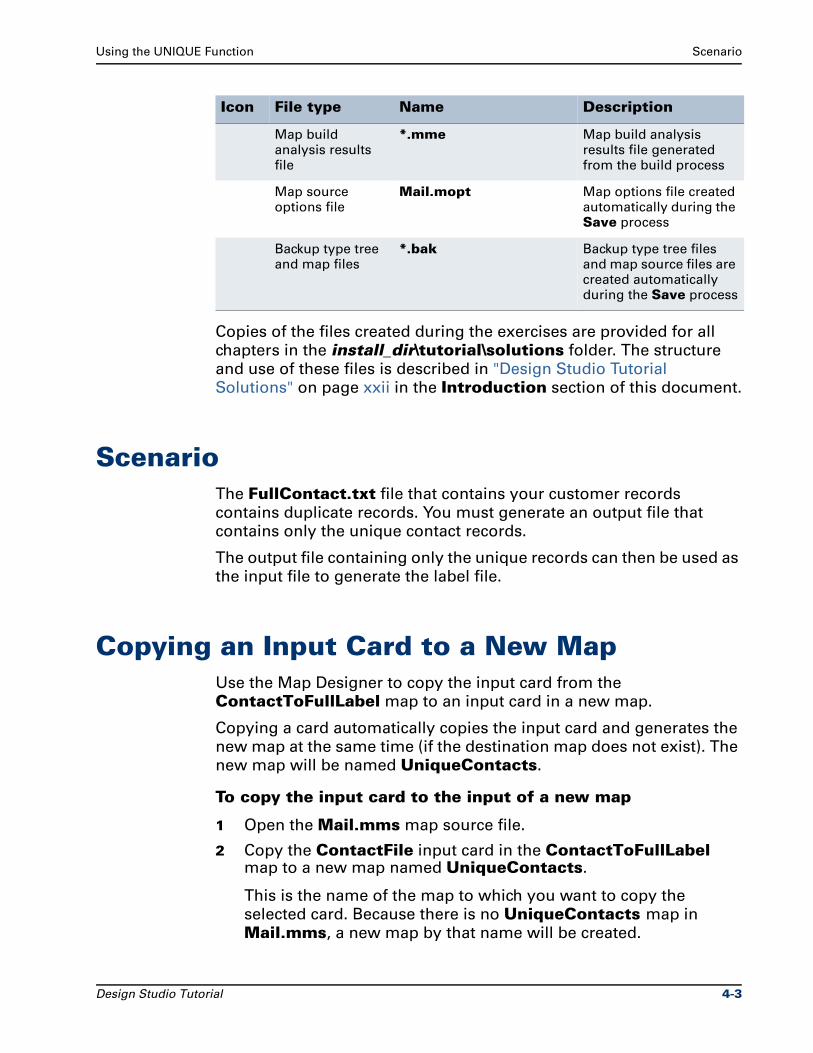
Using the UNIQUE Function Scenario
Copies of the files created during the exercises are provided for all
chapters in the install_dir\tutorial\solutions folder. The structure
and use of these files is described in "Design Studio Tutorial
Solutions" on page xxii in the Introduction section of this document.
ScenarioThe FullContact.txt file that contains your customer records
contains duplicate records. You must generate an output file that
contains only the unique contact records.
The output file containing only the unique records can then be used as
the input file to generate the label file.
Copying an Input Card to a New MapUse the Map Designer to copy the input card from the
ContactToFullLabel map to an input card in a new map.
Copying a card automatically copies the input card and generates the
new map at the same time (if the destination map does not exist). The
new map will be named UniqueContacts.
To copy the input card to the input of a new map
1 Open the Mail.mms map source file.
2 Copy the ContactFile input card in the ContactToFullLabel map to a new map named UniqueContacts.
This is the name of the map to which you want to copy the
selected card. Because there is no UniqueContacts map in
Mail.mms, a new map by that name will be created.
Map build analysis results file
*.mme Map build analysis results file generated from the build process
Map source options file
Mail.mopt Map options file created automatically during the Save process
Backup type tree and map files
*.bak Backup type tree files and map source files are created automatically during the Save process
Icon File type Name Description
Design Studio Tutorial 4-3
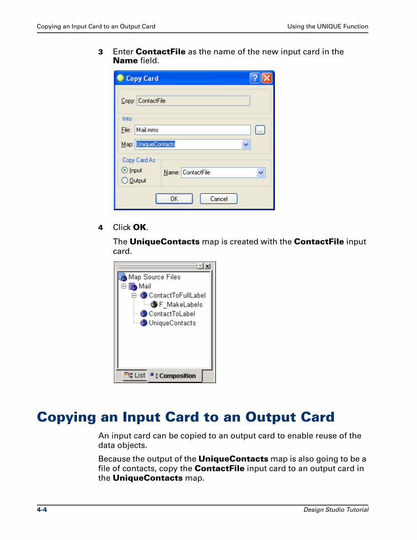
Copying an Input Card to an Output Card Using the UNIQUE Function
3 Enter ContactFile as the name of the new input card in the Name field.
4 Click OK.
The UniqueContacts map is created with the ContactFile input
card.
Copying an Input Card to an Output CardAn input card can be copied to an output card to enable reuse of the
data objects.
Because the output of the UniqueContacts map is also going to be a
file of contacts, copy the ContactFile input card to an output card in
the UniqueContacts map.
4-4 Design Studio Tutorial
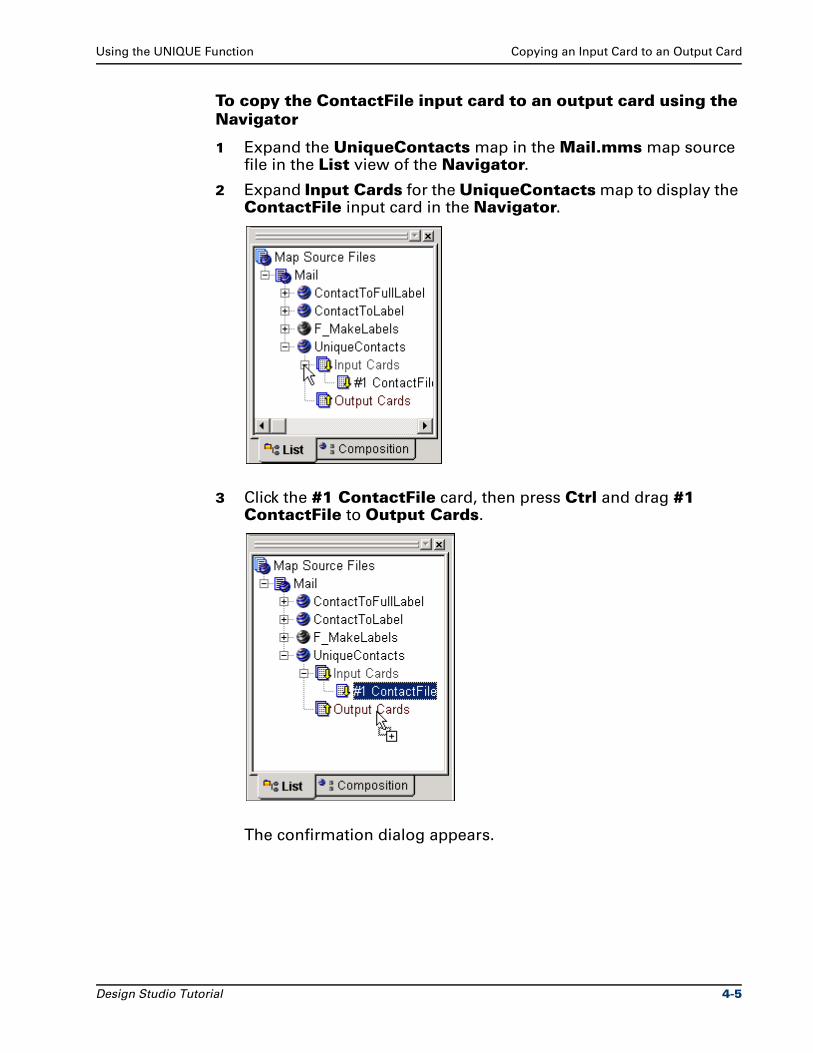
Using the UNIQUE Function Copying an Input Card to an Output Card
To copy the ContactFile input card to an output card using the Navigator
1 Expand the UniqueContacts map in the Mail.mms map source file in the List view of the Navigator.
2 Expand Input Cards for the UniqueContacts map to display the ContactFile input card in the Navigator.
3 Click the #1 ContactFile card, then press Ctrl and drag #1 ContactFile to Output Cards.
The confirmation dialog appears.
Design Studio Tutorial 4-5
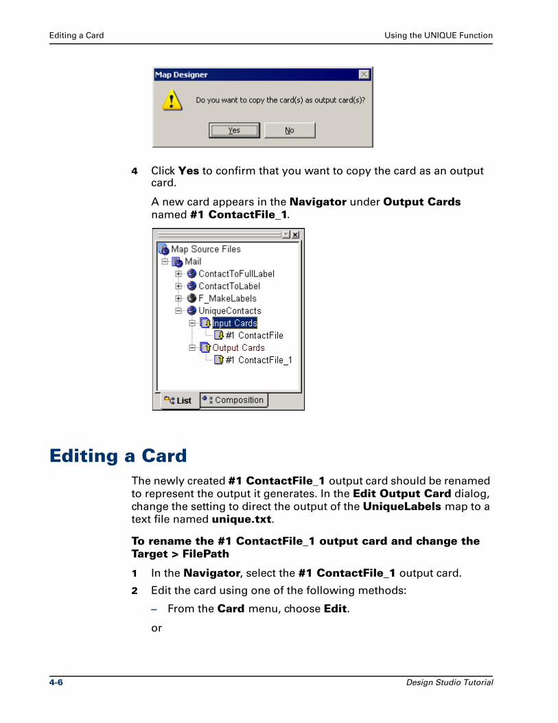
Editing a Card Using the UNIQUE Function
4 Click Yes to confirm that you want to copy the card as an output card.
A new card appears in the Navigator under Output Cards
named #1 ContactFile_1.
Editing a CardThe newly created #1 ContactFile_1 output card should be renamed
to represent the output it generates. In the Edit Output Card dialog,
change the setting to direct the output of the UniqueLabels map to a
text file named unique.txt.
To rename the #1 ContactFile_1 output card and change the Target > FilePath
1 In the Navigator, select the #1 ContactFile_1 output card.
2 Edit the card using one of the following methods:
– From the Card menu, choose Edit.
or
4-6 Design Studio Tutorial
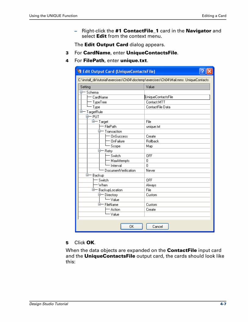
Using the UNIQUE Function Editing a Card
– Right-click the #1 ContactFile_1 card in the Navigator and select Edit from the context menu.
The Edit Output Card dialog appears.
3 For CardName, enter UniqueContactsFile.
4 For FilePath, enter unique.txt.
5 Click OK.
When the data objects are expanded on the ContactFile input card
and the UniqueContactsFile output card, the cards should look like
this:
Design Studio Tutorial 4-7
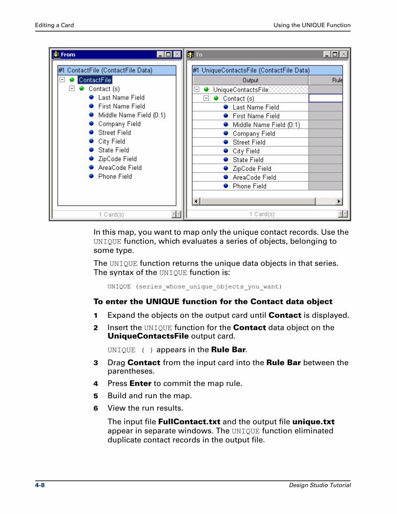
Editing a Card Using the UNIQUE Function
In this map, you want to map only the unique contact records. Use the
UNIQUE function, which evaluates a series of objects, belonging to
some type.
The UNIQUE function returns the unique data objects in that series.
The syntax of the UNIQUE function is:
UNIQUE (series_whose_unique_objects_you_want)
To enter the UNIQUE function for the Contact data object
1 Expand the objects on the output card until Contact is displayed.
2 Insert the UNIQUE function for the Contact data object on the UniqueContactsFile output card.
UNIQUE ( ) appears in the Rule Bar.
3 Drag Contact from the input card into the Rule Bar between the parentheses.
4 Press Enter to commit the map rule.
5 Build and run the map.
6 View the run results.
The input file FullContact.txt and the output file unique.txt
appear in separate windows. The UNIQUE function eliminated
duplicate contact records in the output file.
4-8 Design Studio Tutorial
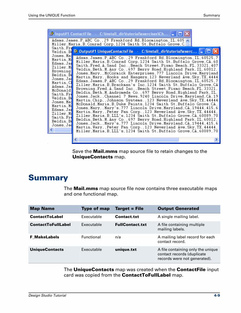
Using the UNIQUE Function Summary
Save the Mail.mms map source file to retain changes to the
UniqueContacts map.
SummaryThe Mail.mms map source file now contains three executable maps
and one functional map.
The UniqueContacts map was created when the ContactFile input
card was copied from the ContactToFullLabel map.
Map Name Type of map Target = File Output Generated
ContactToLabel Executable Contact.txt A single mailing label.
ContactToFullLabel Executable FullContact.txt A file containing multiple mailing labels.
F_MakeLabels Functional n/a A mailing label record for each contact record.
UniqueContacts Executable unique.txt A file containing only the unique contact records (duplicate records were not generated).
Design Studio Tutorial 4-9
Summary Using the UNIQUE Function
When created, the UniqueContacts map contained only the
ContactFile input card that was copied from the
ContactToFullLabel map.
The ContactFile input card was copied to the output card. Copying
the input card to an output card enabled the input data to be mapped.
The UNIQUE function was added to the map rule for the Contact data
object. The output of the map was the unique.txt file, which
contained only the unique records (no duplicate records).
4-10 Design Studio Tutorial
5Using the EXTRACT Function
The ContactToFullLabel map in the Mail.mms map source file can
be modified to extract only the Florida addresses.
ObjectivesThis exercise modifies an existing map and introduces the EXTRACT
function.
By completing the exercises for Chapter 5, you will learn how to:
Modify an existing map.
Use the right-click context menu to edit a card.
Use the EXTRACT function to extract data for which a specified condition is true.
Copy a map.
Files Used in This ChapterYou will be working in the ..\tutorial\my_exercises\ch05 folder.
Design Studio Tutorial 5-1
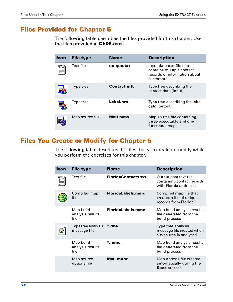
Files Used in This Chapter Using the EXTRACT Function
Files Provided for Chapter 5The following table describes the files provided for this chapter. Use
the files provided in Ch05.exe.
Files You Create or Modify for Chapter 5The following table describes the files that you create or modify while
you perform the exercises for this chapter.
Icon File type Name Description
Text file unique.txt Input data text file that contains multiple contact records of information about customers
Type tree Contact.mtt Type tree describing the contact data (input)
Type tree Label.mtt Type tree describing the label data (output)
Map source file Mail.mms Map source file containing three executable and one functional map
Icon File type Name Description
Text file FloridaContacts.txt Output data text file containing contact records with Florida addresses
Compiled map file
FloridaLabels.mmc Compiled map file that creates a file of unique records from Florida
Map build analysis results file
FloridaLabels.mme Map build analysis results file generated from the build process
Type tree analysis message file
*.dbe Type tree analysis message file created when a type tree is analyzed
Map build analysis results file
*.mme Map build analysis results file generated from the build process
Map source options file
Mail.mopt Map options file created automatically during the Save process
5-2 Design Studio Tutorial
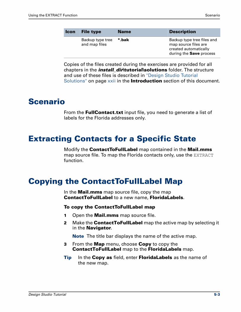
Using the EXTRACT Function Scenario
Copies of the files created during the exercises are provided for all
chapters in the install_dir\tutorial\solutions folder. The structure
and use of these files is described in "Design Studio Tutorial
Solutions" on page xxii in the Introduction section of this document.
ScenarioFrom the FullContact.txt input file, you need to generate a list of
labels for the Florida addresses only.
Extracting Contacts for a Specific StateModify the ContactToFullLabel map contained in the Mail.mms
map source file. To map the Florida contacts only, use the EXTRACT
function.
Copying the ContactToFullLabel MapIn the Mail.mms map source file, copy the map
ContactToFullLabel to a new name, FloridaLabels.
To copy the ContactToFullLabel map
1 Open the Mail.mms map source file.
2 Make the ContactToFullLabel map the active map by selecting it in the Navigator.
Note The title bar displays the name of the active map.
3 From the Map menu, choose Copy to copy the ContactToFullLabel map to the FloridaLabels map.
Tip In the Copy as field, enter FloridaLabels as the name of
the new map.
Backup type tree and map files
*.bak Backup type tree files and map source files are created automatically during the Save process
Icon File type Name Description
Design Studio Tutorial 5-3
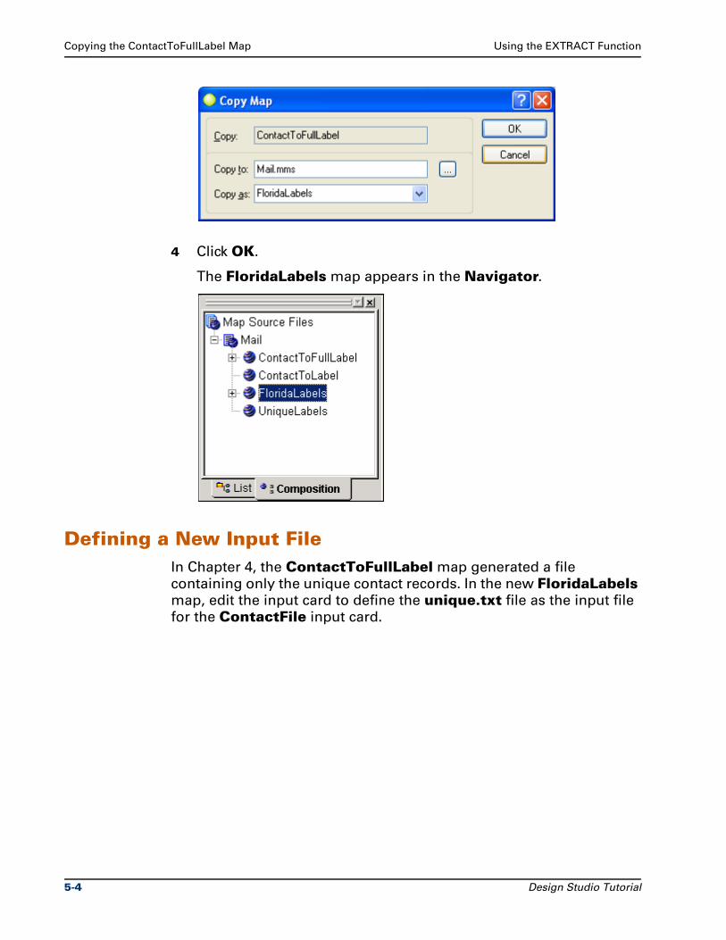
Copying the ContactToFullLabel Map Using the EXTRACT Function
4 Click OK.
The FloridaLabels map appears in the Navigator.
Defining a New Input FileIn Chapter 4, the ContactToFullLabel map generated a file
containing only the unique contact records. In the new FloridaLabels
map, edit the input card to define the unique.txt file as the input file
for the ContactFile input card.
5-4 Design Studio Tutorial
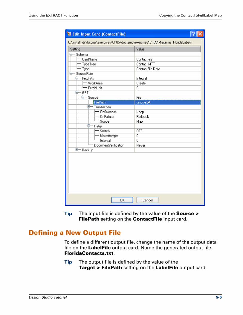
Using the EXTRACT Function Copying the ContactToFullLabel Map
Tip The input file is defined by the value of the Source > FilePath setting on the ContactFile input card.
Defining a New Output FileTo define a different output file, change the name of the output data
file on the LabelFile output card. Name the generated output file
FloridaContacts.txt.
Tip The output file is defined by the value of the
Target > FilePath setting on the LabelFile output card.
Design Studio Tutorial 5-5
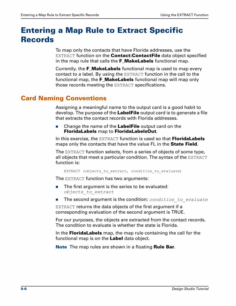
Entering a Map Rule to Extract Specific Records Using the EXTRACT Function
Entering a Map Rule to Extract Specific Records
To map only the contacts that have Florida addresses, use the
EXTRACT function on the Contact:ContactFile data object specified
in the map rule that calls the F_MakeLabels functional map.
Currently, the F_MakeLabels functional map is used to map every
contact to a label. By using the EXTRACT function in the call to the
functional map, the F_MakeLabels functional map will map only
those records meeting the EXTRACT specifications.
Card Naming ConventionsAssigning a meaningful name to the output card is a good habit to
develop. The purpose of the LabelFile output card is to generate a file
that extracts the contact records with Florida addresses.
Change the name of the LabelFile output card on the FloridaLabels map to FloridaLabelsOut.
In this exercise, the EXTRACT function is used so that FloridaLabels
maps only the contacts that have the value FL in the State Field.
The EXTRACT function selects, from a series of objects of some type,
all objects that meet a particular condition. The syntax of the EXTRACT
function is:
EXTRACT (objects_to_extract, condition_to_evaluate)
The EXTRACT function has two arguments:
The first argument is the series to be evaluated: objects_to_extract
The second argument is the condition: condition_to_evaluate
EXTRACT returns the data objects of the first argument if a
corresponding evaluation of the second argument is TRUE.
For our purposes, the objects are extracted from the contact records.
The condition to evaluate is whether the state is Florida.
In the FloridaLabels map, the map rule containing the call for the
functional map is on the Label data object.
Note The map rules are shown in a floating Rule Bar.
5-6 Design Studio Tutorial
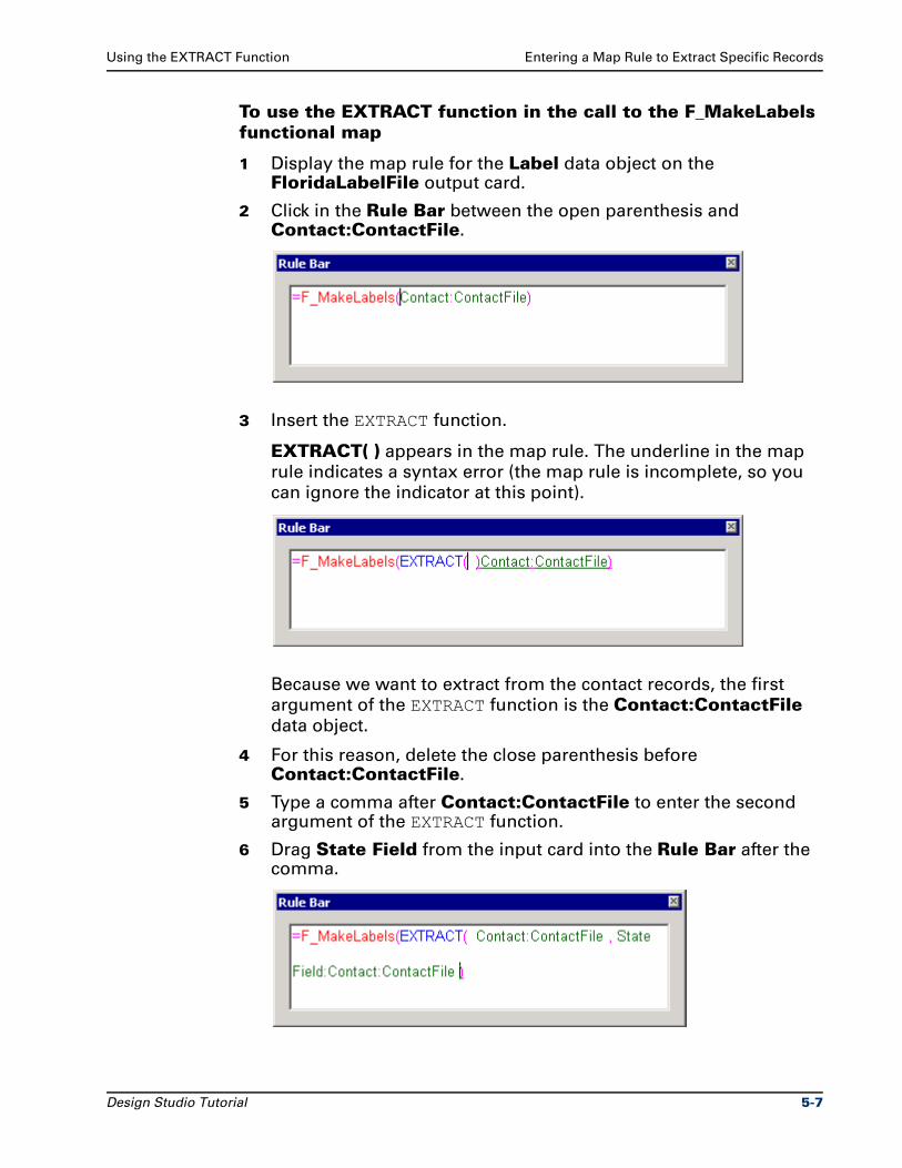
Using the EXTRACT Function Entering a Map Rule to Extract Specific Records
To use the EXTRACT function in the call to the F_MakeLabels functional map
1 Display the map rule for the Label data object on the FloridaLabelFile output card.
2 Click in the Rule Bar between the open parenthesis and Contact:ContactFile.
3 Insert the EXTRACT function.
EXTRACT( ) appears in the map rule. The underline in the map
rule indicates a syntax error (the map rule is incomplete, so you
can ignore the indicator at this point).
Because we want to extract from the contact records, the first
argument of the EXTRACT function is the Contact:ContactFile
data object.
4 For this reason, delete the close parenthesis before Contact:ContactFile.
5 Type a comma after Contact:ContactFile to enter the second argument of the EXTRACT function.
6 Drag State Field from the input card into the Rule Bar after the comma.
Design Studio Tutorial 5-7
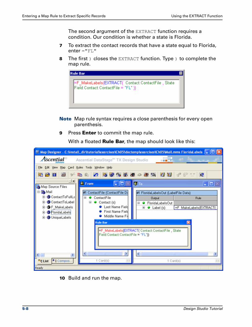
Entering a Map Rule to Extract Specific Records Using the EXTRACT Function
The second argument of the EXTRACT function requires a
condition. Our condition is whether a state is Florida.
7 To extract the contact records that have a state equal to Florida, enter ="FL"
8 The first ) closes the EXTRACT function. Type ) to complete the map rule.
Note Map rule syntax requires a close parenthesis for every open
parenthesis.
9 Press Enter to commit the map rule.
With a floated Rule Bar, the map should look like this:
10 Build and run the map.
5-8 Design Studio Tutorial
Using the EXTRACT Function Summary
11 View the run results.
The unique.txt input file and the FloridaContacts.txt output
file are displayed in separate windows.
Each label that was generated has the value FL for the State Field. Two records contain Florida addresses.
12 Save the Mail.mms map source file.
Optionally, copy the FloridaLabels map to a different name. Modify
the EXTRACT map rule to extract a different state.
Note Close all maps, type trees, and text files.
SummaryThe Mail.mms map source file now contains the FloridaLabels
executable map.
The FloridaLabels executable map was created as a copy of the
ContactToFullLabel map.
You changed the source of the input card. You defined a new target for
the output card. You defined a map rule to extract the contact records
for Florida addresses.
The FloridaLabels.txt file was generated with two Florida addresses.
Note Close all maps, type trees, and text files.
Design Studio Tutorial 5-9

Summary Using the EXTRACT Function
5-10 Design Studio Tutorial
6Using the OR Function With a Lookup
File
You need to generate labels for only the preferred customers in the
address file.
ObjectivesThis exercise introduces creating type trees and the concept of
creating a lookup file.
By completing the exercises for Chapter 6, you will learn how to:
Create a type tree that represents preferred customers.
Change type properties in the Properties window.
Use type inheritance for creating subtypes.
Define group types as Explicit or Implicit.
Define terminators and delimiters.
Index the output object to generate a specific number of occurrences.
Use the TODATETIME function to convert a text literal to a date format.
Generate a lookup file of preferred customers as output of a map.
Design Studio Tutorial 6-1
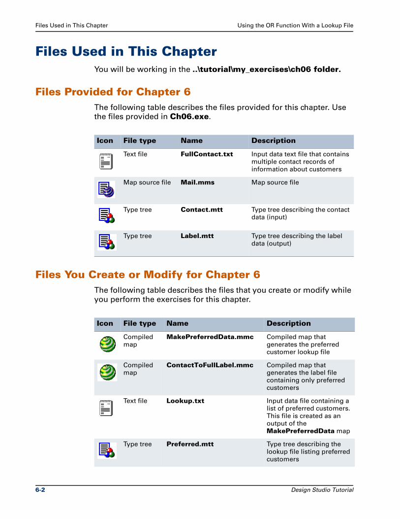
Files Used in This Chapter Using the OR Function With a Lookup File
Files Used in This ChapterYou will be working in the ..\tutorial\my_exercises\ch06 folder.
Files Provided for Chapter 6The following table describes the files provided for this chapter. Use
the files provided in Ch06.exe.
Files You Create or Modify for Chapter 6The following table describes the files that you create or modify while
you perform the exercises for this chapter.
Icon File type Name Description
Text file FullContact.txt Input data text file that contains multiple contact records of information about customers
Map source file Mail.mms Map source file
Type tree Contact.mtt Type tree describing the contact data (input)
Type tree Label.mtt Type tree describing the label data (output)
Icon File type Name Description
Compiled map
MakePreferredData.mmc Compiled map that generates the preferred customer lookup file
Compiled map
ContactToFullLabel.mmc Compiled map that generates the label file containing only preferred customers
Text file Lookup.txt Input data file containing a list of preferred customers. This file is created as an output of the MakePreferredData map
Type tree Preferred.mtt Type tree describing the lookup file listing preferred customers
6-2 Design Studio Tutorial
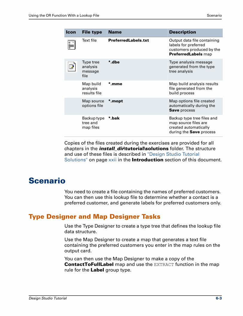
Using the OR Function With a Lookup File Scenario
Copies of the files created during the exercises are provided for all
chapters in the install_dir\tutorial\solutions folder. The structure
and use of these files is described in "Design Studio Tutorial
Solutions" on page xxii in the Introduction section of this document.
ScenarioYou need to create a file containing the names of preferred customers.
You can then use this lookup file to determine whether a contact is a
preferred customer, and generate labels for preferred customers only.
Type Designer and Map Designer TasksUse the Type Designer to create a type tree that defines the lookup file
data structure.
Use the Map Designer to create a map that generates a text file
containing the preferred customers you enter in the map rules on the
output card.
You can then use the Map Designer to make a copy of the
ContactToFullLabel map and use the EXTRACT function in the map
rule for the Label group type.
Text file PreferredLabels.txt Output data file containing labels for preferred customers produced by the PreferredLabels map
Type tree analysis message file
*.dbe Type analysis message generated from the type tree analysis
Map build analysis results file
*.mme Map build analysis results file generated from the build process
Map source options file
*.mopt Map options file created automatically during the Save process
Backup type tree and map files
*.bak Backup type tree files and map source files are created automatically during the Save process
Icon File type Name Description
Design Studio Tutorial 6-3
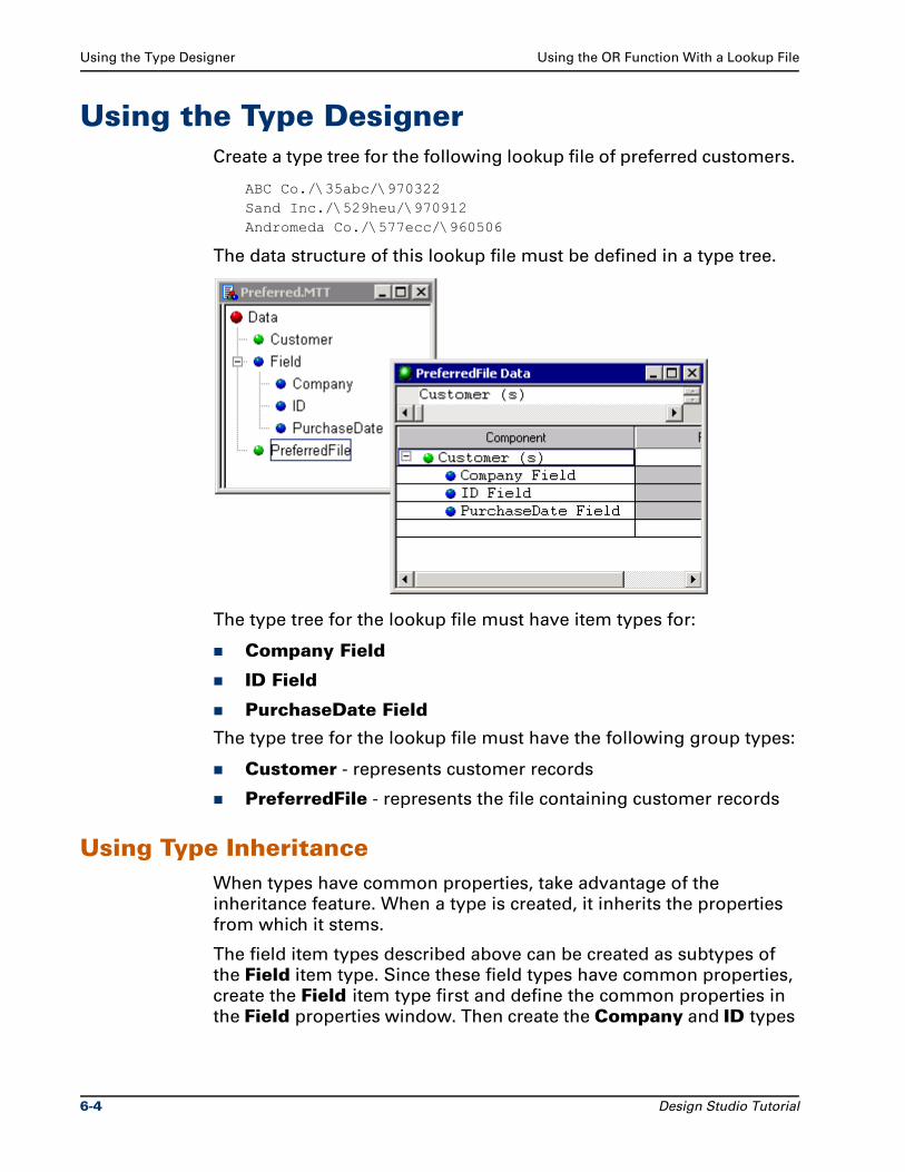
Using the Type Designer Using the OR Function With a Lookup File
Using the Type DesignerCreate a type tree for the following lookup file of preferred customers.
ABC Co./\35abc/\970322Sand Inc./\529heu/\970912Andromeda Co./\577ecc/\960506
The data structure of this lookup file must be defined in a type tree.
The type tree for the lookup file must have item types for:
Company Field
ID Field
PurchaseDate Field
The type tree for the lookup file must have the following group types:
Customer - represents customer records
PreferredFile - represents the file containing customer records
Using Type InheritanceWhen types have common properties, take advantage of the
inheritance feature. When a type is created, it inherits the properties
from which it stems.
The field item types described above can be created as subtypes of
the Field item type. Since these field types have common properties,
create the Field item type first and define the common properties in
the Field properties window. Then create the Company and ID types
6-4 Design Studio Tutorial
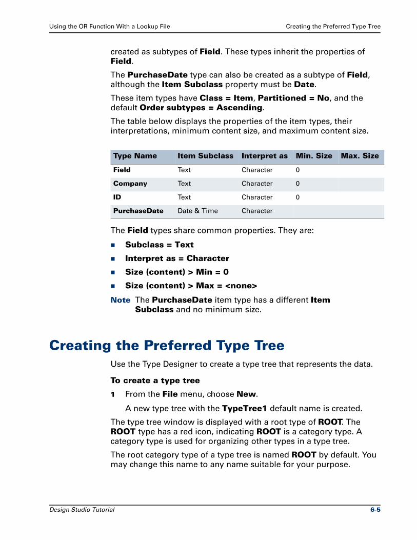
Using the OR Function With a Lookup File Creating the Preferred Type Tree
created as subtypes of Field. These types inherit the properties of
Field.
The PurchaseDate type can also be created as a subtype of Field,
although the Item Subclass property must be Date.
These item types have Class = Item, Partitioned = No, and the
default Order subtypes = Ascending.
The table below displays the properties of the item types, their
interpretations, minimum content size, and maximum content size.
The Field types share common properties. They are:
Subclass = Text
Interpret as = Character
Size (content) > Min = 0
Size (content) > Max = <none>
Note The PurchaseDate item type has a different Item Subclass and no minimum size.
Creating the Preferred Type TreeUse the Type Designer to create a type tree that represents the data.
To create a type tree
1 From the File menu, choose New.
A new type tree with the TypeTree1 default name is created.
The type tree window is displayed with a root type of ROOT. The
ROOT type has a red icon, indicating ROOT is a category type. A
category type is used for organizing other types in a type tree.
The root category type of a type tree is named ROOT by default. You
may change this name to any name suitable for your purpose.
Type Name Item Subclass Interpret as Min. Size Max. Size
Field Text Character 0
Company Text Character 0
ID Text Character 0
PurchaseDate Date & Time Character
Design Studio Tutorial 6-5
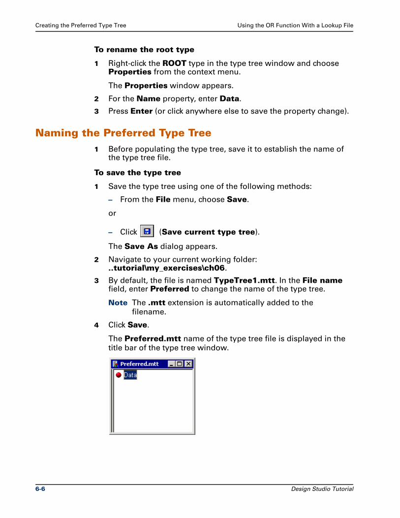
Creating the Preferred Type Tree Using the OR Function With a Lookup File
To rename the root type
1 Right-click the ROOT type in the type tree window and choose Properties from the context menu.
The Properties window appears.
2 For the Name property, enter Data.
3 Press Enter (or click anywhere else to save the property change).
Naming the Preferred Type Tree1 Before populating the type tree, save it to establish the name of
the type tree file.
To save the type tree
1 Save the type tree using one of the following methods:
– From the File menu, choose Save.
or
– Click (Save current type tree).
The Save As dialog appears.
2 Navigate to your current working folder: ..tutorial\my_exercises\ch06.
3 By default, the file is named TypeTree1.mtt. In the File name field, enter Preferred to change the name of the type tree.
Note The .mtt extension is automatically added to the
filename.
4 Click Save.
The Preferred.mtt name of the type tree file is displayed in the
title bar of the type tree window.
6-6 Design Studio Tutorial
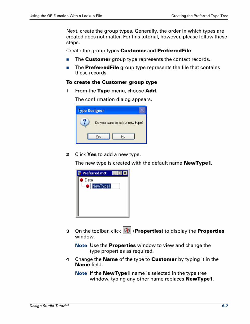
Using the OR Function With a Lookup File Creating the Preferred Type Tree
Next, create the group types. Generally, the order in which types are
created does not matter. For this tutorial, however, please follow these
steps.
Create the group types Customer and PreferredFile.
The Customer group type represents the contact records.
The PreferredFile group type represents the file that contains these records.
To create the Customer group type
1 From the Type menu, choose Add.
The confirmation dialog appears.
2 Click Yes to add a new type.
The new type is created with the default name NewType1.
3 On the toolbar, click (Properties) to display the Properties
window.
Note Use the Properties window to view and change the
type properties as required.
4 Change the Name of the type to Customer by typing it in the Name field.
Note If the NewType1 name is selected in the type tree
window, typing any other name replaces NewType1.
Design Studio Tutorial 6-7

Creating the Preferred Type Tree Using the OR Function With a Lookup File
5 Change the Class to Group by selecting the Group class from the Class drop-down list.
The confirmation dialog appears.
6 Click Yes to change the class of the Customer type from Category to Group.
The green color of the icon in the type tree window indicates the
Customer type is a group type.
Creating the PreferredFile Group TypeCreate the PreferredFile group type.
A new type appears as a subtype of the type that is highlighted.
Tip Select the Data root type before creating the PreferredFile
group type.
The default Group Subclass > Format property of Implicit is correct for the PreferredFile group type.
Creating the Field Item TypesCreate the Field item type and assign to it the properties that are
common to all the field types. The other field types created as
subtypes of Field automatically inherit these properties.
6-8 Design Studio Tutorial
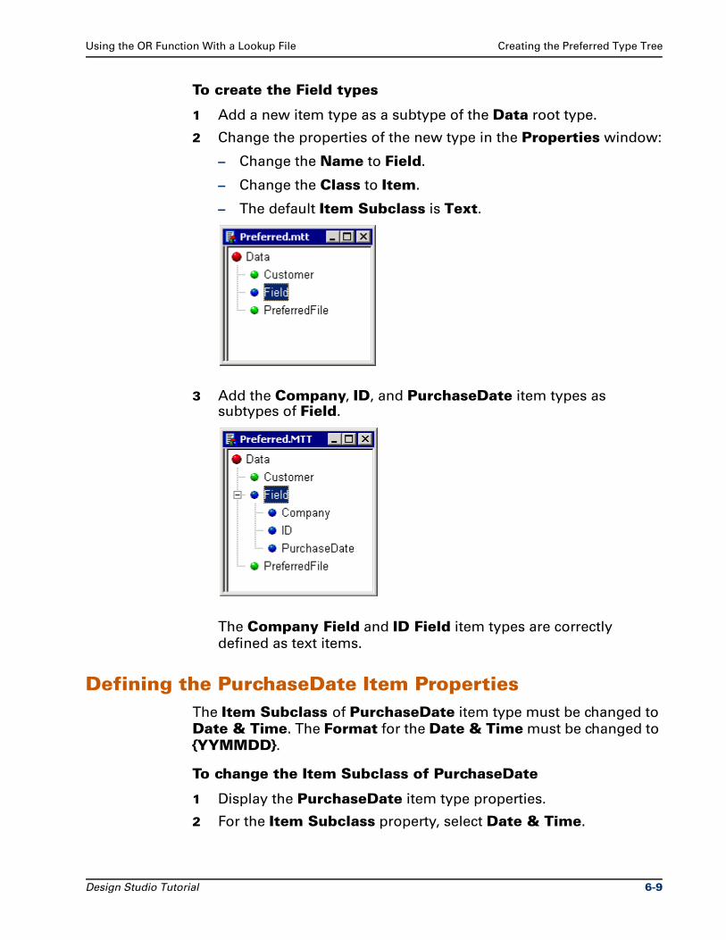
Using the OR Function With a Lookup File Creating the Preferred Type Tree
To create the Field types
1 Add a new item type as a subtype of the Data root type.
2 Change the properties of the new type in the Properties window:
– Change the Name to Field.
– Change the Class to Item.
– The default Item Subclass is Text.
3 Add the Company, ID, and PurchaseDate item types as subtypes of Field.
The Company Field and ID Field item types are correctly
defined as text items.
Defining the PurchaseDate Item PropertiesThe Item Subclass of PurchaseDate item type must be changed to
Date & Time. The Format for the Date & Time must be changed to
{YYMMDD}.
To change the Item Subclass of PurchaseDate
1 Display the PurchaseDate item type properties.
2 For the Item Subclass property, select Date & Time.
Design Studio Tutorial 6-9
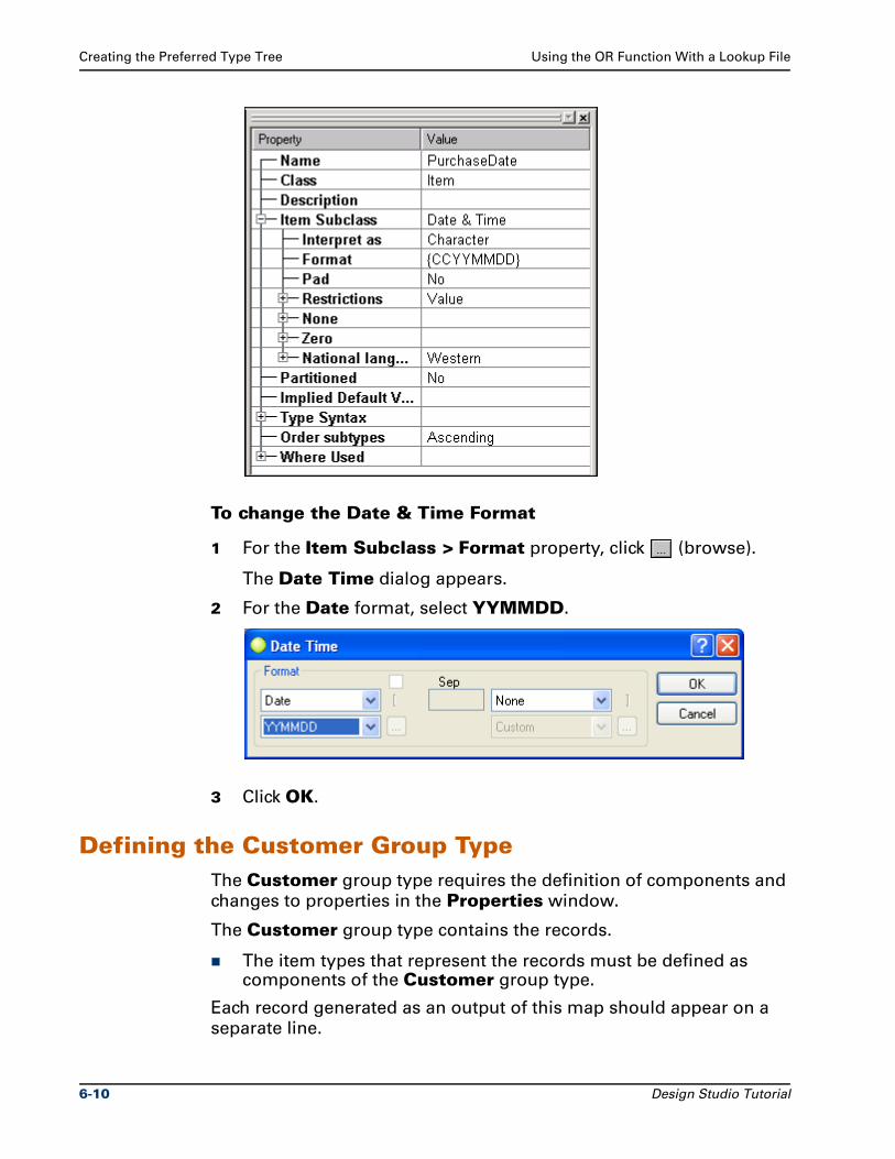
Creating the Preferred Type Tree Using the OR Function With a Lookup File
To change the Date & Time Format
1 For the Item Subclass > Format property, click (browse).
The Date Time dialog appears.
2 For the Date format, select YYMMDD.
3 Click OK.
Defining the Customer Group TypeThe Customer group type requires the definition of components and
changes to properties in the Properties window.
The Customer group type contains the records.
The item types that represent the records must be defined as components of the Customer group type.
Each record generated as an output of this map should appear on a
separate line.
6-10 Design Studio Tutorial

Using the OR Function With a Lookup File Creating the Preferred Type Tree
To generate one record per line, records must be terminated with a <NL>.
Each field in the record is delimited with forward and backward
slashes /\.
The Component Syntax must be Delimited.
The Delimiter > Value must be defined with the literal delimiters.
The explicit format relies on syntax to separate components. Each
component of the record can be identified by the /\ delimiter in the
data.
The Customer group type must be defined with Format = Explicit.
Note To access help on any type property, put focus on that
property in the Properties window and press F1.
To define the components of the Customer type
1 Double-click the Customer type in the type tree window.
The Customer group window appears.
2 Drag the components from the type tree window to the Customer group window.
3 Arrange the components of Customer Data in the order they appear in the data: Company Field, ID Field, and then PurchaseDate Field.
4 Close and save the Customer group window.
Design Studio Tutorial 6-11
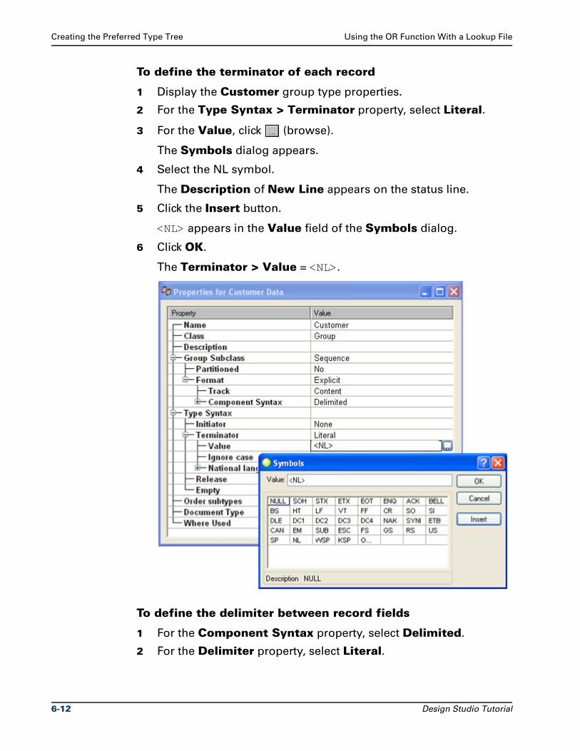
Creating the Preferred Type Tree Using the OR Function With a Lookup File
To define the terminator of each record
1 Display the Customer group type properties.
2 For the Type Syntax > Terminator property, select Literal.
3 For the Value, click (browse).
The Symbols dialog appears.
4 Select the NL symbol.
The Description of New Line appears on the status line.
5 Click the Insert button.
<NL> appears in the Value field of the Symbols dialog.
6 Click OK.
The Terminator > Value = <NL>.
To define the delimiter between record fields
1 For the Component Syntax property, select Delimited.
2 For the Delimiter property, select Literal.
6-12 Design Studio Tutorial
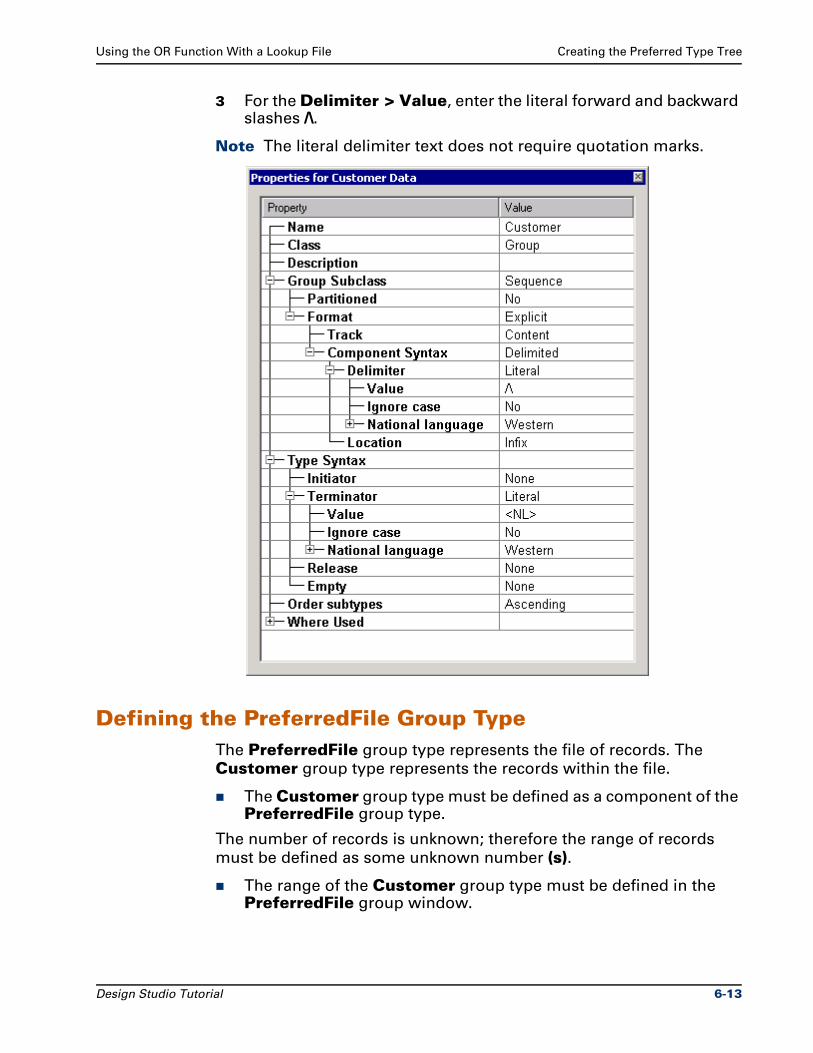
Using the OR Function With a Lookup File Creating the Preferred Type Tree
3 For the Delimiter > Value, enter the literal forward and backward slashes /\.
Note The literal delimiter text does not require quotation marks.
Defining the PreferredFile Group TypeThe PreferredFile group type represents the file of records. The
Customer group type represents the records within the file.
The Customer group type must be defined as a component of the PreferredFile group type.
The number of records is unknown; therefore the range of records
must be defined as some unknown number (s).
The range of the Customer group type must be defined in the PreferredFile group window.
Design Studio Tutorial 6-13
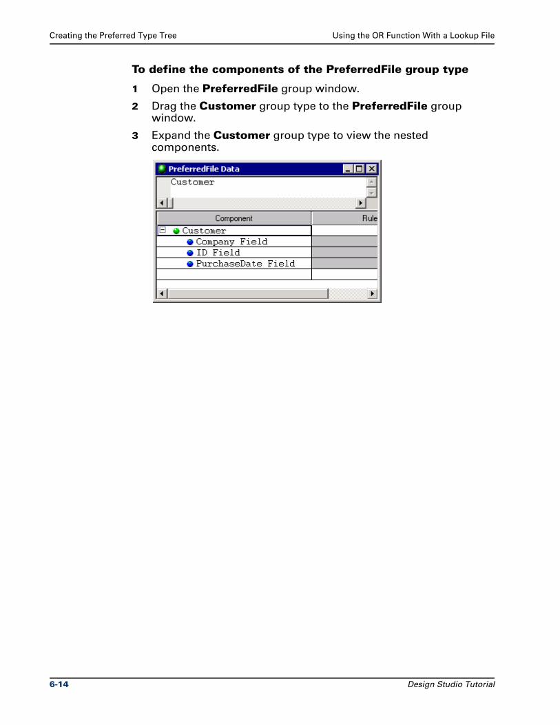
Creating the Preferred Type Tree Using the OR Function With a Lookup File
To define the components of the PreferredFile group type
1 Open the PreferredFile group window.
2 Drag the Customer group type to the PreferredFile group window.
3 Expand the Customer group type to view the nested components.
6-14 Design Studio Tutorial
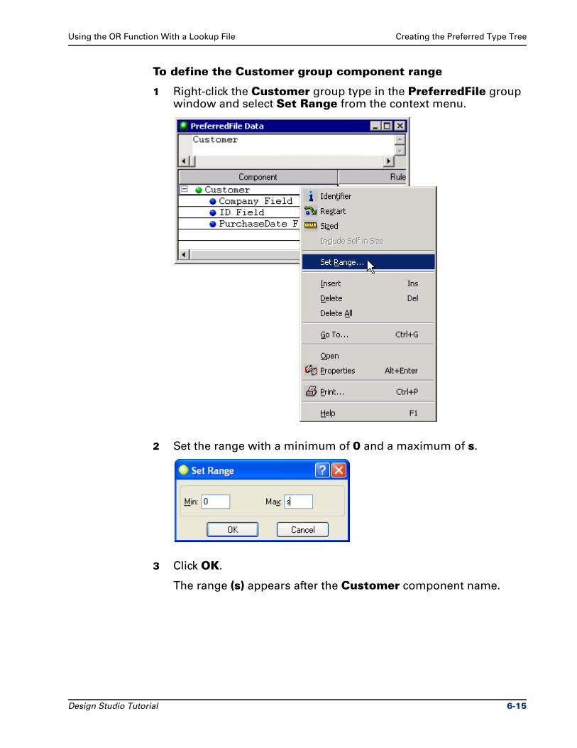
Using the OR Function With a Lookup File Creating the Preferred Type Tree
To define the Customer group component range
1 Right-click the Customer group type in the PreferredFile group window and select Set Range from the context menu.
2 Set the range with a minimum of 0 and a maximum of s.
3 Click OK.
The range (s) appears after the Customer component name.
Design Studio Tutorial 6-15
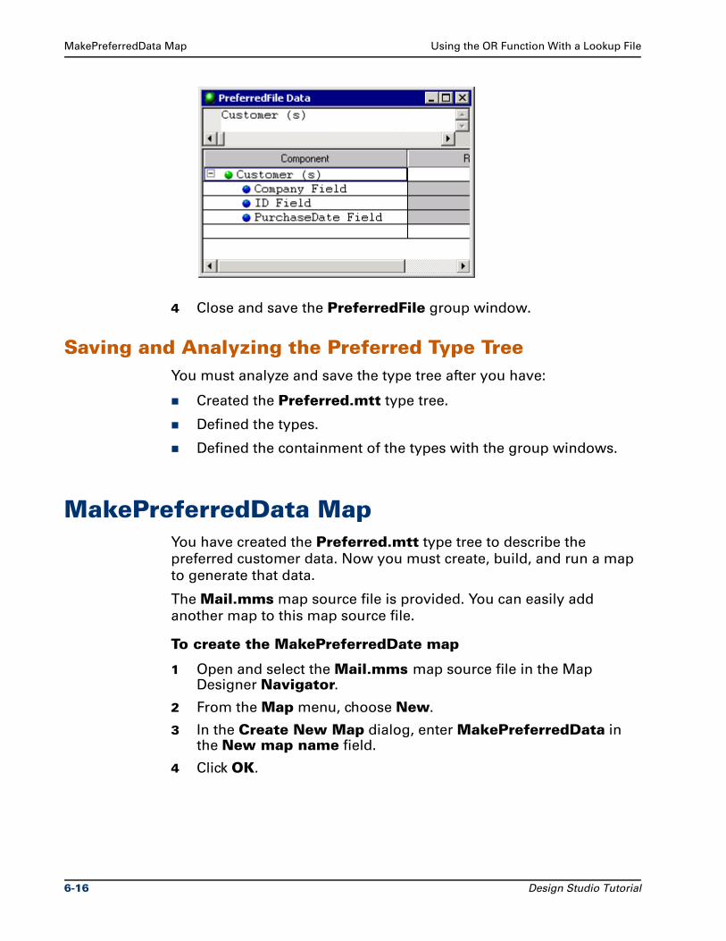
MakePreferredData Map Using the OR Function With a Lookup File
4 Close and save the PreferredFile group window.
Saving and Analyzing the Preferred Type TreeYou must analyze and save the type tree after you have:
Created the Preferred.mtt type tree.
Defined the types.
Defined the containment of the types with the group windows.
MakePreferredData MapYou have created the Preferred.mtt type tree to describe the
preferred customer data. Now you must create, build, and run a map
to generate that data.
The Mail.mms map source file is provided. You can easily add
another map to this map source file.
To create the MakePreferredDate map
1 Open and select the Mail.mms map source file in the Map Designer Navigator.
2 From the Map menu, choose New.
3 In the Create New Map dialog, enter MakePreferredData in the New map name field.
4 Click OK.
6-16 Design Studio Tutorial
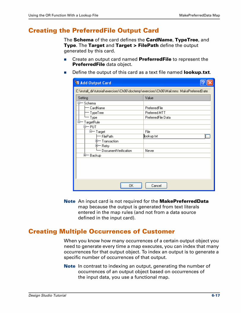
Using the OR Function With a Lookup File MakePreferredData Map
Creating the PreferredFile Output CardThe Schema of the card defines the CardName, TypeTree, and
Type. The Target and Target > FilePath define the output
generated by this card.
Create an output card named PreferredFile to represent the PreferredFile data object.
Define the output of this card as a text file named lookup.txt.
Note An input card is not required for the MakePreferredData
map because the output is generated from text literals
entered in the map rules (and not from a data source
defined in the input card).
Creating Multiple Occurrences of CustomerWhen you know how many occurrences of a certain output object you
need to generate every time a map executes, you can index that many
occurrences for that output object. To index an output is to generate a
specific number of occurrences of that output.
Note In contrast to indexing an output, generating the number of
occurrences of an output object based on occurrences of
the input data, you use a functional map.
Design Studio Tutorial 6-17
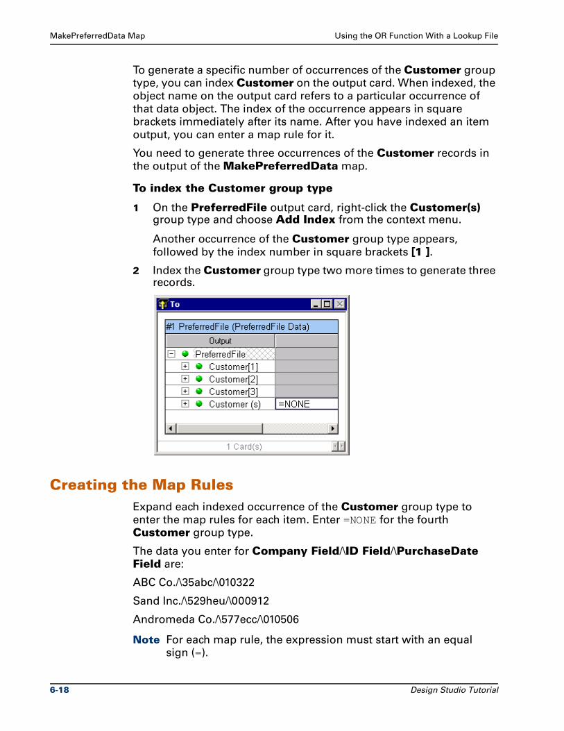
MakePreferredData Map Using the OR Function With a Lookup File
To generate a specific number of occurrences of the Customer group
type, you can index Customer on the output card. When indexed, the
object name on the output card refers to a particular occurrence of
that data object. The index of the occurrence appears in square
brackets immediately after its name. After you have indexed an item
output, you can enter a map rule for it.
You need to generate three occurrences of the Customer records in
the output of the MakePreferredData map.
To index the Customer group type
1 On the PreferredFile output card, right-click the Customer(s) group type and choose Add Index from the context menu.
Another occurrence of the Customer group type appears,
followed by the index number in square brackets [1 ].
2 Index the Customer group type two more times to generate three records.
Creating the Map RulesExpand each indexed occurrence of the Customer group type to
enter the map rules for each item. Enter =NONE for the fourth
Customer group type.
The data you enter for Company Field/\ID Field/\PurchaseDate Field are:
ABC Co./\35abc/\010322
Sand Inc./\529heu/\000912
Andromeda Co./\577ecc/\010506
Note For each map rule, the expression must start with an equal
sign (=).
6-18 Design Studio Tutorial
Using the OR Function With a Lookup File MakePreferredData Map
To enter the literal map rules
1 For the Company Field component of Customer, enter the literal company names enclosed in quotation marks.
2 For the ID Field component, enter the literal text enclosed in quotation marks.
3 For the PurchaseDate Field, you must enter the literal text for the date and convert this to a date time format using the TODATETIME function. (For detailed instructions about this, refer to "Using the TODATETIME Function" .)
4 To enter =NONE for the Customer(s) group type, from the Rules menu, choose Insert NONE if Empty.
Using the TODATETIME FunctionThe TODATETIME function converts a text string of a specified format
to a date/time. The text string for the PurchaseDate Field on the
PreferredFile output card #1 is a 6-character numeric date text literal.
For example, for Customer[1] the text literal is "010322".
The syntax of the TODATETIME function is
TODATETIME (text_to_convert [ , {date_time_format_string} ] )
The text_to_convert is the text literal date you enter in the map rule.
The date_time_format_string specifies the date time format.
– The default format for the date_time_format_string is CCYYMMDDHH24MMSS.
– The text literal of "010322" does not match the default date time format. Therefore, you must specify the format of YYMMDD.
To convert the text literal to a date
1 In the PreferredFile output card #1 map rule for the PurchaseDate Field, insert the TODATETIME function.
=TODATETIME () appears in the Rule Bar
2 In the parentheses, enter:
– The text_to_convert
– A comma (,)
– The date_time_format_string enclosed in quotation marks " "
Design Studio Tutorial 6-19
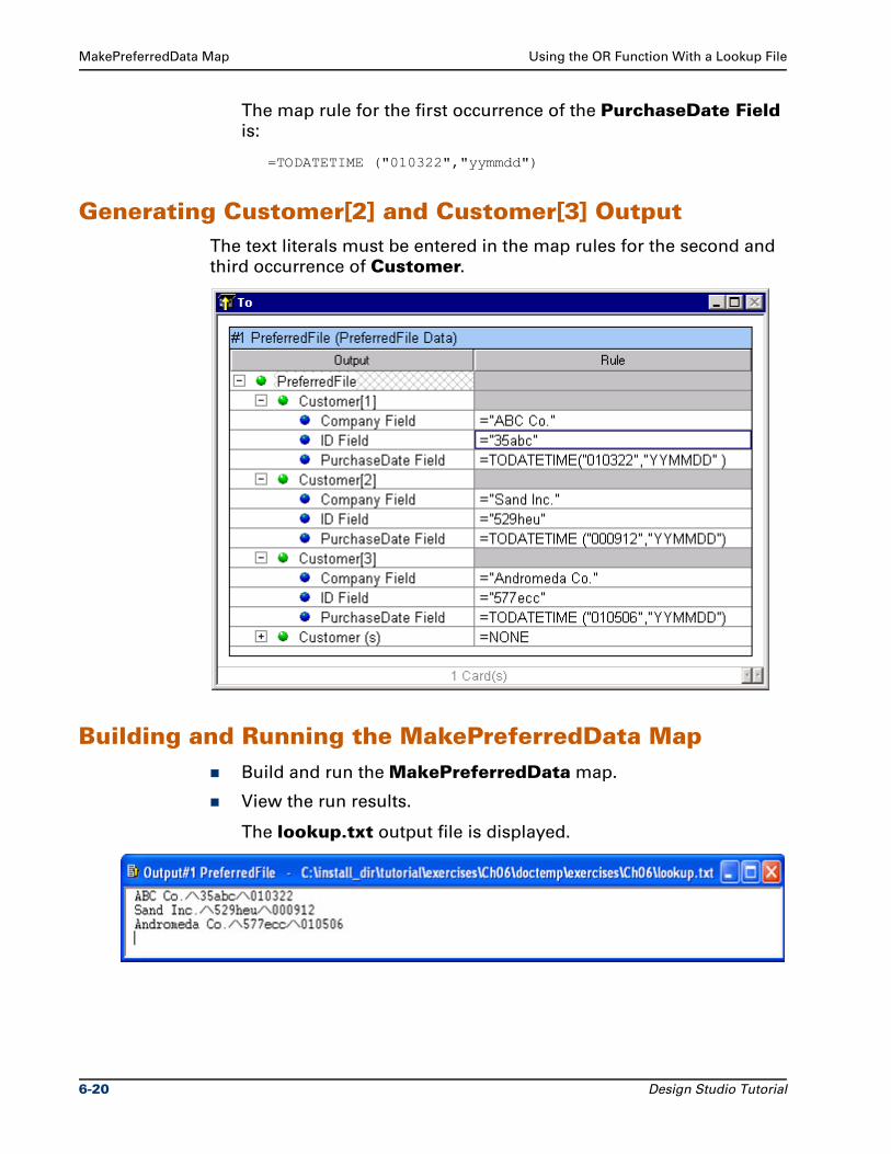
MakePreferredData Map Using the OR Function With a Lookup File
The map rule for the first occurrence of the PurchaseDate Field
is:
=TODATETIME ("010322","yymmdd")
Generating Customer[2] and Customer[3] OutputThe text literals must be entered in the map rules for the second and
third occurrence of Customer.
Building and Running the MakePreferredData MapBuild and run the MakePreferredData map.
View the run results.
The lookup.txt output file is displayed.
6-20 Design Studio Tutorial
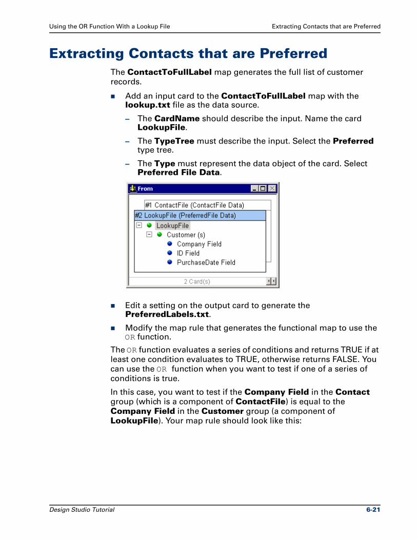
Using the OR Function With a Lookup File Extracting Contacts that are Preferred
Extracting Contacts that are PreferredThe ContactToFullLabel map generates the full list of customer
records.
Add an input card to the ContactToFullLabel map with the lookup.txt file as the data source.
– The CardName should describe the input. Name the card LookupFile.
– The TypeTree must describe the input. Select the Preferred type tree.
– The Type must represent the data object of the card. Select Preferred File Data.
Edit a setting on the output card to generate the PreferredLabels.txt.
Modify the map rule that generates the functional map to use the OR function.
The OR function evaluates a series of conditions and returns TRUE if at
least one condition evaluates to TRUE, otherwise returns FALSE. You
can use the OR function when you want to test if one of a series of
conditions is true.
In this case, you want to test if the Company Field in the Contact
group (which is a component of ContactFile) is equal to the
Company Field in the Customer group (a component of
LookupFile). Your map rule should look like this:
Design Studio Tutorial 6-21
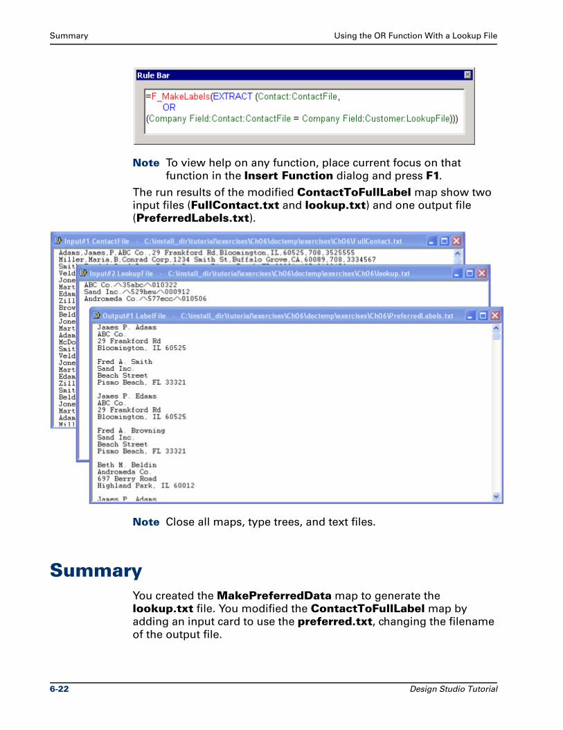
Summary Using the OR Function With a Lookup File
Note To view help on any function, place current focus on that
function in the Insert Function dialog and press F1.
The run results of the modified ContactToFullLabel map show two
input files (FullContact.txt and lookup.txt) and one output file
(PreferredLabels.txt).
Note Close all maps, type trees, and text files.
SummaryYou created the MakePreferredData map to generate the
lookup.txt file. You modified the ContactToFullLabel map by
adding an input card to use the preferred.txt, changing the filename
of the output file.
6-22 Design Studio Tutorial
Using the OR Function With a Lookup File Summary
The call for the functional map uses the OR function and the EXTRACT
function to generate a list of labels for preferred customers only.
Design Studio Tutorial 6-23

Summary Using the OR Function With a Lookup File
6-24 Design Studio Tutorial
7Using Cross-Referenced Data
This chapter explains how to decide which function to use when
cross-referencing data, and how to use that function. A map example
using each of these functions is provided.
ObjectivesThis chapter defines how to cross-reference data from another source
and incorporate it into the output.
By completing the exercises for Chapter 7, you will learn how to:
Create group types to represent records.
Create group types to represent files of records.
Add components to group types.
Define component ranges.
Use the LOOKUP function to locate an object in a list that is not organized in any particular order.
Use the SORTDOWN function to locate an object in a list that is in descending order.
Use the SEARCHUP function to locate an object in a list that is in ascending order.
[Optional] Use the SORTUP function to locate an object in a list that is in ascending order.
[Optional] Use the SEARCHDOWN function to locate an object in a list that is in descending order.
Design Studio Tutorial 7-1
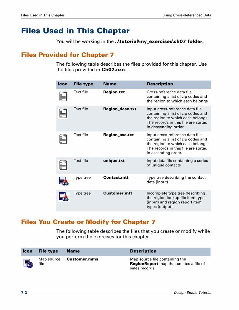
Files Used in This Chapter Using Cross-Referenced Data
Files Used in This ChapterYou will be working in the ..\tutorial\my_exercises\ch07 folder.
Files Provided for Chapter 7The following table describes the files provided for this chapter. Use
the files provided in Ch07.exe.
Files You Create or Modify for Chapter 7The following table describes the files that you create or modify while
you perform the exercises for this chapter.
Icon File type Name Description
Text file Region.txt Cross-reference data file containing a list of zip codes and the region to which each belongs
Text file Region_desc.txt Input cross-reference data file containing a list of zip codes and the region to which each belongs. The records in this file are sorted in descending order.
Text file Region_asc.txt Input cross-reference data file containing a list of zip codes and the region to which each belongs. The records in this file are sorted in ascending order.
Text file unique.txt Input data file containing a series of unique contacts
Type tree Contact.mtt Type tree describing the contact data (input)
Type tree Customer.mtt Incomplete type tree describing the region lookup file item types (input) and region report item types (output)
Icon File type Name Description
Map source file
Customer.mms Map source file containing the RegionReport map that creates a file of sales records
7-2 Design Studio Tutorial
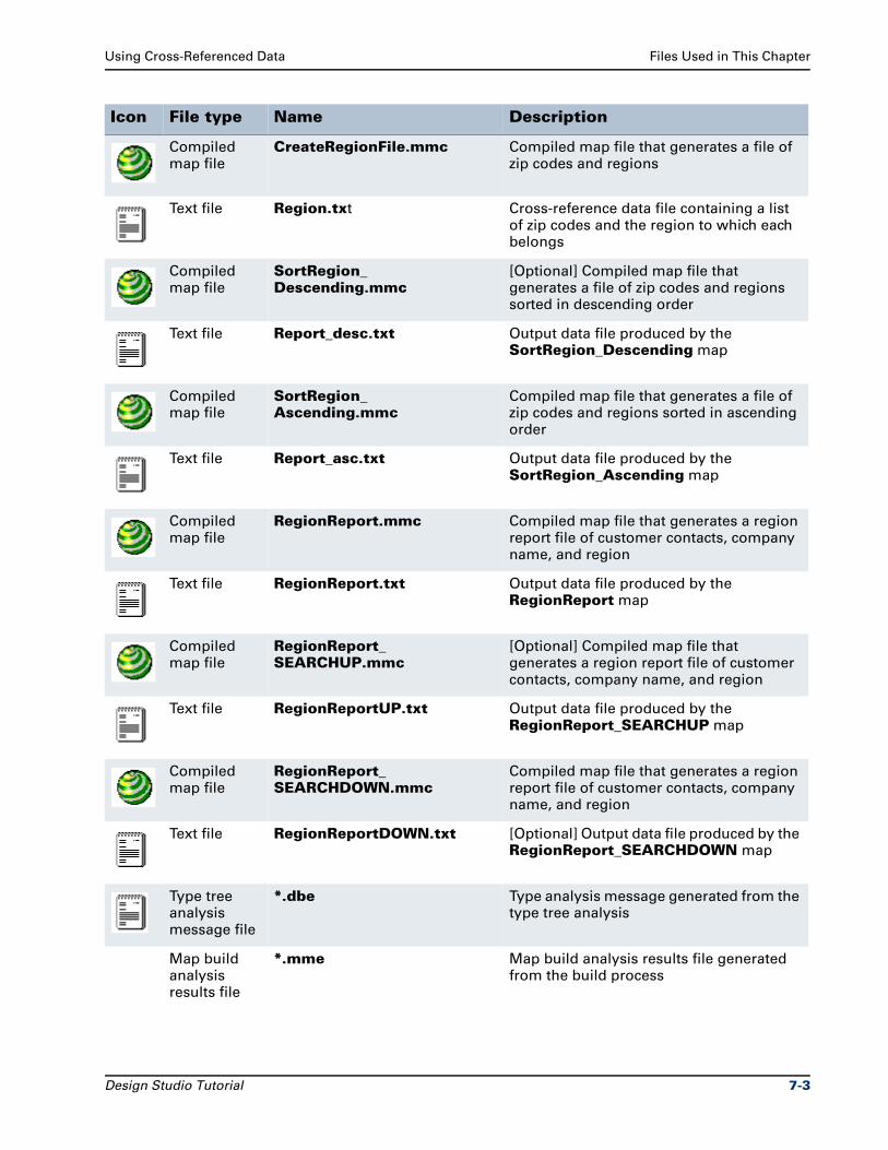
Using Cross-Referenced Data Files Used in This Chapter
Compiled map file
CreateRegionFile.mmc Compiled map file that generates a file of zip codes and regions
Text file Region.txt Cross-reference data file containing a list of zip codes and the region to which each belongs
Compiled map file
SortRegion_Descending.mmc
[Optional] Compiled map file that generates a file of zip codes and regions sorted in descending order
Text file Report_desc.txt Output data file produced by the SortRegion_Descending map
Compiled map file
SortRegion_Ascending.mmc
Compiled map file that generates a file of zip codes and regions sorted in ascending order
Text file Report_asc.txt Output data file produced by the SortRegion_Ascending map
Compiled map file
RegionReport.mmc Compiled map file that generates a region report file of customer contacts, company name, and region
Text file RegionReport.txt Output data file produced by the RegionReport map
Compiled map file
RegionReport_SEARCHUP.mmc
[Optional] Compiled map file that generates a region report file of customer contacts, company name, and region
Text file RegionReportUP.txt Output data file produced by the RegionReport_SEARCHUP map
Compiled map file
RegionReport_SEARCHDOWN.mmc
Compiled map file that generates a region report file of customer contacts, company name, and region
Text file RegionReportDOWN.txt [Optional] Output data file produced by the RegionReport_SEARCHDOWN map
Type tree analysis message file
*.dbe Type analysis message generated from the type tree analysis
Map build analysis results file
*.mme Map build analysis results file generated from the build process
Icon File type Name Description
Design Studio Tutorial 7-3
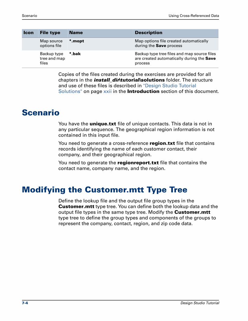
Scenario Using Cross-Referenced Data
Copies of the files created during the exercises are provided for all
chapters in the install_dir\tutorial\solutions folder. The structure
and use of these files is described in "Design Studio Tutorial
Solutions" on page xxii in the Introduction section of this document.
ScenarioYou have the unique.txt file of unique contacts. This data is not in
any particular sequence. The geographical region information is not
contained in this input file.
You need to generate a cross-reference region.txt file that contains
records identifying the name of each customer contact, their
company, and their geographical region.
You need to generate the regionreport.txt file that contains the
contact name, company name, and the region.
Modifying the Customer.mtt Type TreeDefine the lookup file and the output file group types in the
Customer.mtt type tree. You can define both the lookup data and the
output file types in the same type tree. Modify the Customer.mtt
type tree to define the group types and components of the groups to
represent the company, contact, region, and zip code data.
Map source options file
*.mopt Map options file created automatically during the Save process
Backup type tree and map files
*.bak Backup type tree files and map source files are created automatically during the Save process
Icon File type Name Description
7-4 Design Studio Tutorial
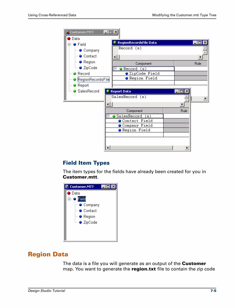
Using Cross-Referenced Data Modifying the Customer.mtt Type Tree
Field Item Types
The item types for the fields have already been created for you in
Customer.mtt.
Region DataThe data is a file you will generate as an output of the Customer
map. You want to generate the region.txt file to contain the zip code
Design Studio Tutorial 7-5
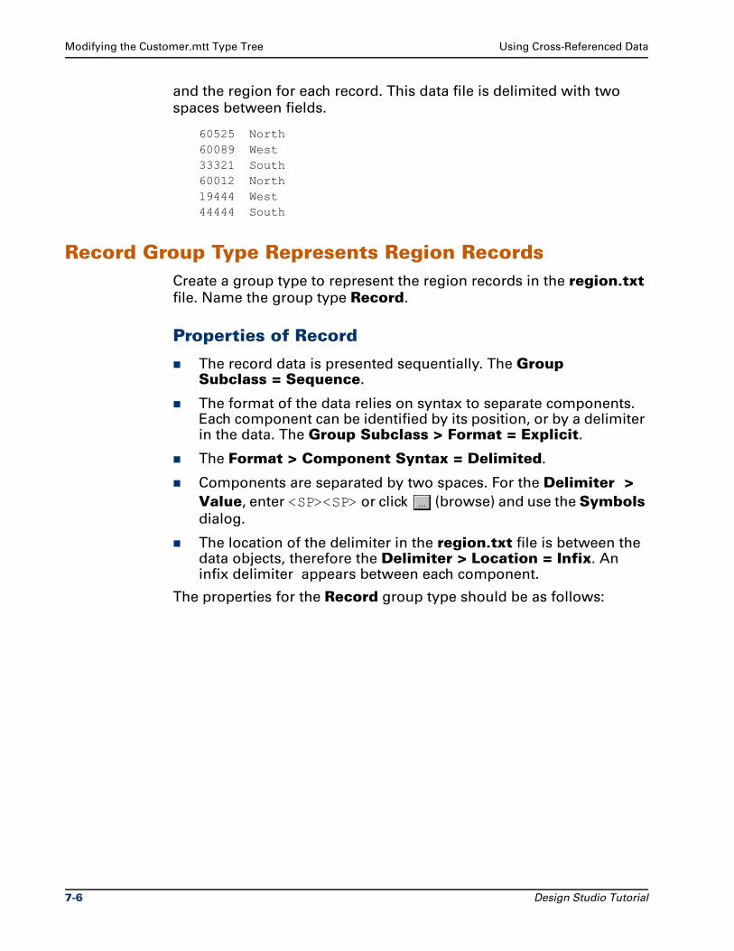
Modifying the Customer.mtt Type Tree Using Cross-Referenced Data
and the region for each record. This data file is delimited with two
spaces between fields.
60525 North60089 West33321 South60012 North19444 West44444 South
Record Group Type Represents Region RecordsCreate a group type to represent the region records in the region.txt
file. Name the group type Record.
Properties of Record
The record data is presented sequentially. The Group Subclass = Sequence.
The format of the data relies on syntax to separate components. Each component can be identified by its position, or by a delimiter in the data. The Group Subclass > Format = Explicit.
The Format > Component Syntax = Delimited.
Components are separated by two spaces. For the Delimiter > Value, enter <SP><SP> or click (browse) and use the Symbols
dialog.
The location of the delimiter in the region.txt file is between the data objects, therefore the Delimiter > Location = Infix. An infix delimiter appears between each component.
The properties for the Record group type should be as follows:
7-6 Design Studio Tutorial
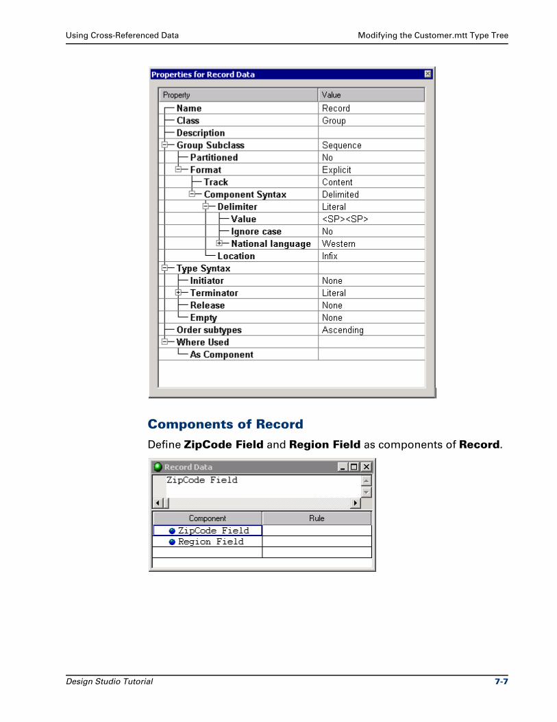
Using Cross-Referenced Data Modifying the Customer.mtt Type Tree
Components of Record
Define ZipCode Field and Region Field as components of Record.
Design Studio Tutorial 7-7
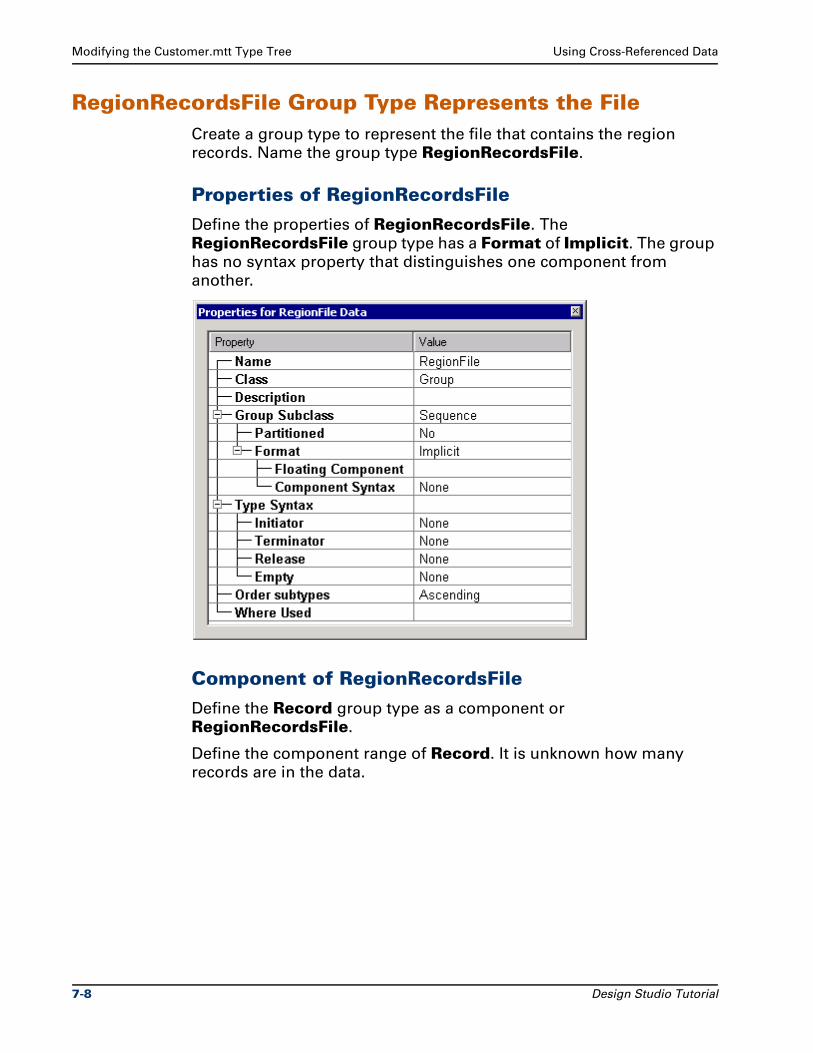
Modifying the Customer.mtt Type Tree Using Cross-Referenced Data
RegionRecordsFile Group Type Represents the FileCreate a group type to represent the file that contains the region
records. Name the group type RegionRecordsFile.
Properties of RegionRecordsFile
Define the properties of RegionRecordsFile. The
RegionRecordsFile group type has a Format of Implicit. The group
has no syntax property that distinguishes one component from
another.
Component of RegionRecordsFile
Define the Record group type as a component or
RegionRecordsFile.
Define the component range of Record. It is unknown how many
records are in the data.
7-8 Design Studio Tutorial
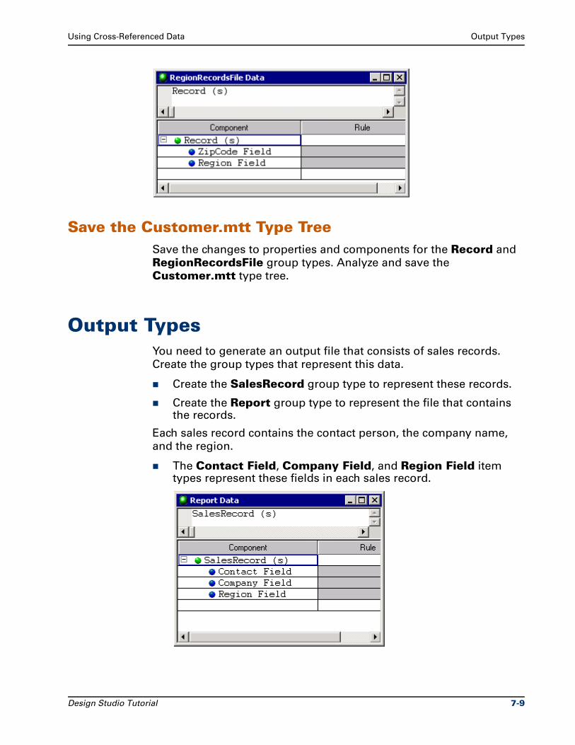
Using Cross-Referenced Data Output Types
Save the Customer.mtt Type TreeSave the changes to properties and components for the Record and
RegionRecordsFile group types. Analyze and save the
Customer.mtt type tree.
Output TypesYou need to generate an output file that consists of sales records.
Create the group types that represent this data.
Create the SalesRecord group type to represent these records.
Create the Report group type to represent the file that contains the records.
Each sales record contains the contact person, the company name,
and the region.
The Contact Field, Company Field, and Region Field item types represent these fields in each sales record.
Design Studio Tutorial 7-9
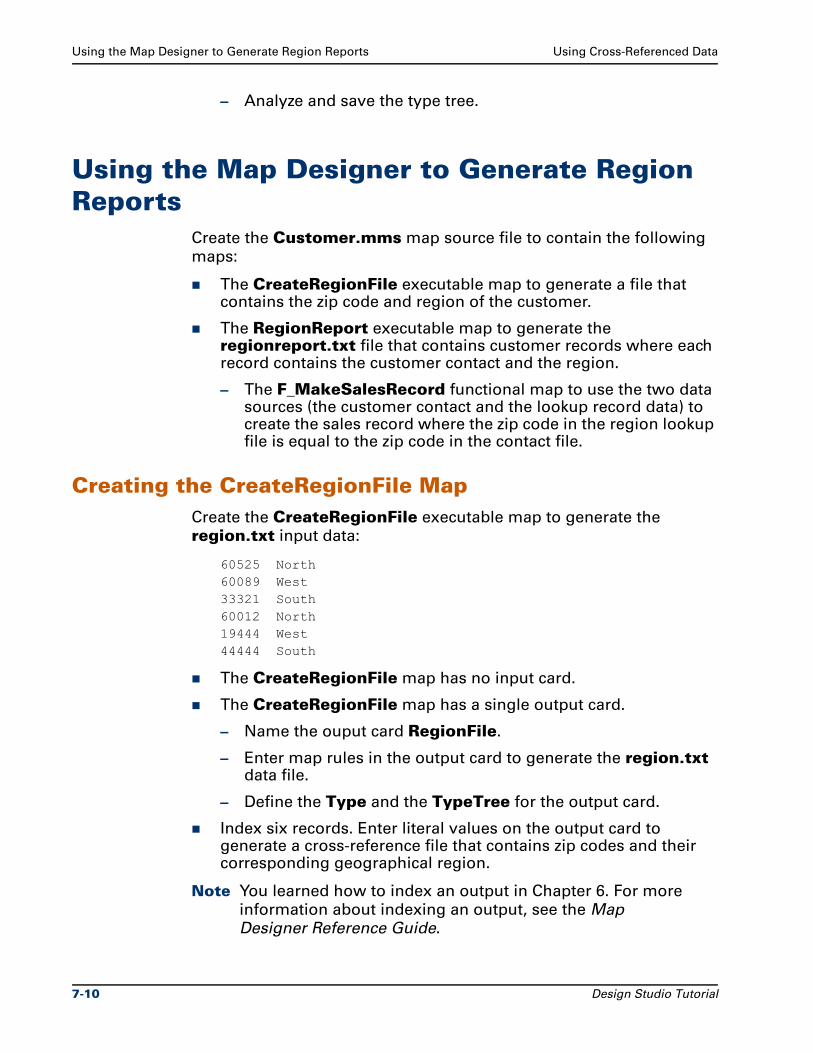
Using the Map Designer to Generate Region Reports Using Cross-Referenced Data
– Analyze and save the type tree.
Using the Map Designer to Generate Region Reports
Create the Customer.mms map source file to contain the following
maps:
The CreateRegionFile executable map to generate a file that contains the zip code and region of the customer.
The RegionReport executable map to generate the regionreport.txt file that contains customer records where each record contains the customer contact and the region.
– The F_MakeSalesRecord functional map to use the two data sources (the customer contact and the lookup record data) to create the sales record where the zip code in the region lookup file is equal to the zip code in the contact file.
Creating the CreateRegionFile MapCreate the CreateRegionFile executable map to generate the
region.txt input data:
60525 North60089 West33321 South60012 North19444 West44444 South
The CreateRegionFile map has no input card.
The CreateRegionFile map has a single output card.
– Name the ouput card RegionFile.
– Enter map rules in the output card to generate the region.txt data file.
– Define the Type and the TypeTree for the output card.
Index six records. Enter literal values on the output card to generate a cross-reference file that contains zip codes and their corresponding geographical region.
Note You learned how to index an output in Chapter 6. For more
information about indexing an output, see the Map
Designer Reference Guide.
7-10 Design Studio Tutorial

Using Cross-Referenced Data Using the Map Designer to Generate Region Reports
Generate no output for the last object on the card.
Build and run this map to generate the region.txt output file.
Save the CreateRegionFile map.
Design Studio Tutorial 7-11
Creating the RegionReport Map Using Cross-Referenced Data
Creating the RegionReport MapCreate an executable map called RegionReport to generate the regionreport.txt output file. The regionreport.txt file will contain
customer records where each record contains the customer contact
and the region.
Define the unique.txt contact file as the data source for input card #1.
Define the region.txt lookup file as the data source for input card #2.
In the map rule for the RegionReport data object on the output card:
Specify the generation of the F_MakeSalesRecord functional map.
Use the LOOKUP function because the lookup file is not ordered in any specific way.
Define the regionreport.txt as the data target.
Creating the F_MakeSalesRecord Functional Map
The two input objects for the F_MakeSalesRecord functional map
are the Contact group type from input card #1 and the Record group
type from input card #2.
Using the LOOKUP FunctionSpecify the LOOKUP function to sequentially search the series of
contacts, and return the first member of the series that meets a
specified condition.
The LOOKUP function has two arguments.
The first argument is the series of objects to search: series_to_search
The series to search is the customer contacts, as represented by
the Contact group type on input card #1.
The second argument is the condition on which to base the search: condition_to_evaluate
The condition to evaluate is whether the zip code of the record in
the region.txt lookup file is equal to the zip code of the contact in
the unique.txt file.
7-12 Design Studio Tutorial
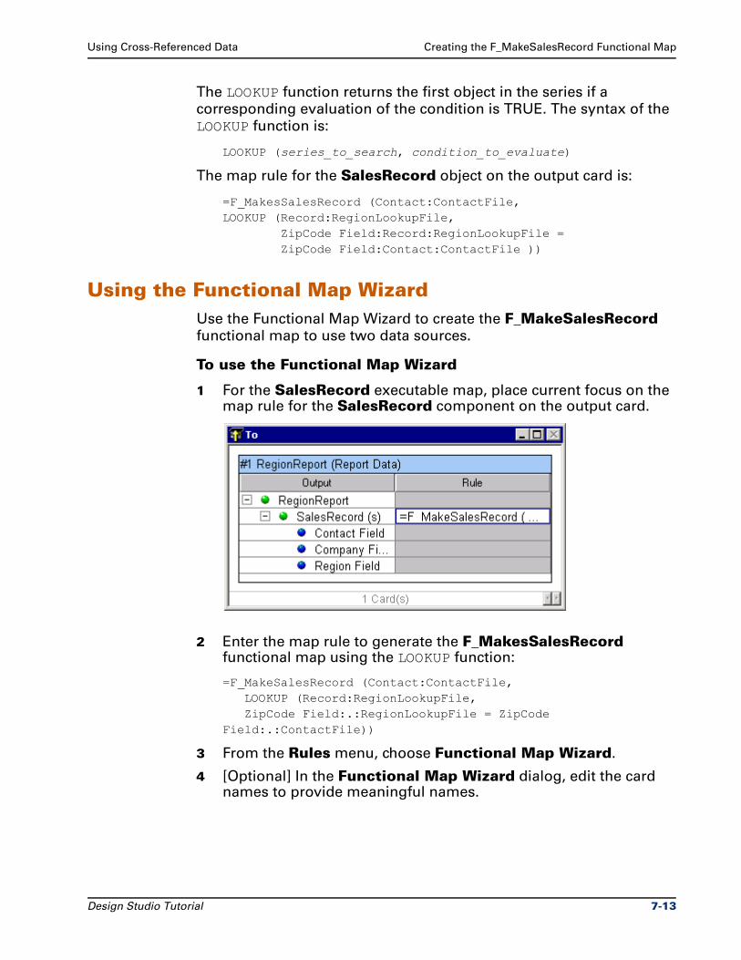
Using Cross-Referenced Data Creating the F_MakeSalesRecord Functional Map
The LOOKUP function returns the first object in the series if a
corresponding evaluation of the condition is TRUE. The syntax of the
LOOKUP function is:
LOOKUP (series_to_search, condition_to_evaluate)
The map rule for the SalesRecord object on the output card is:
=F_MakesSalesRecord (Contact:ContactFile,LOOKUP (Record:RegionLookupFile, ZipCode Field:Record:RegionLookupFile = ZipCode Field:Contact:ContactFile ))
Using the Functional Map WizardUse the Functional Map Wizard to create the F_MakeSalesRecord
functional map to use two data sources.
To use the Functional Map Wizard
1 For the SalesRecord executable map, place current focus on the map rule for the SalesRecord component on the output card.
2 Enter the map rule to generate the F_MakesSalesRecord functional map using the LOOKUP function:
=F_MakeSalesRecord (Contact:ContactFile,LOOKUP (Record:RegionLookupFile,ZipCode Field:.:RegionLookupFile = ZipCode
Field:.:ContactFile))
3 From the Rules menu, choose Functional Map Wizard.
4 [Optional] In the Functional Map Wizard dialog, edit the card names to provide meaningful names.
Design Studio Tutorial 7-13
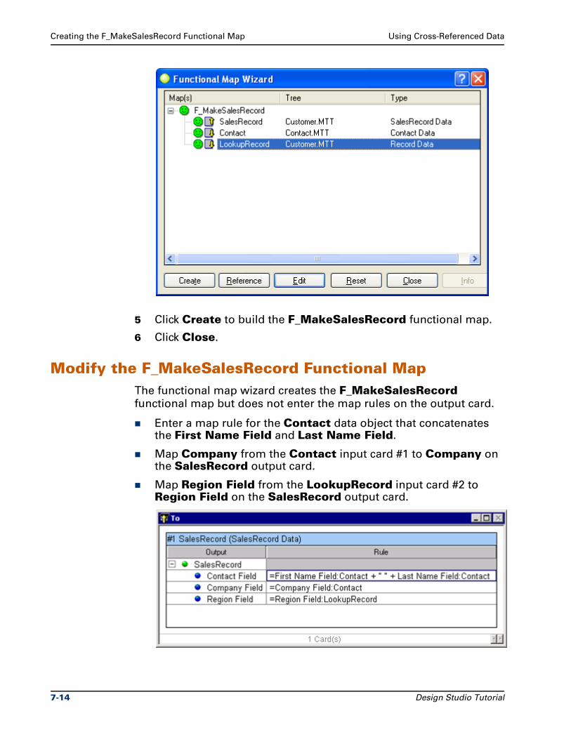
Creating the F_MakeSalesRecord Functional Map Using Cross-Referenced Data
5 Click Create to build the F_MakeSalesRecord functional map.
6 Click Close.
Modify the F_MakeSalesRecord Functional MapThe functional map wizard creates the F_MakeSalesRecord
functional map but does not enter the map rules on the output card.
Enter a map rule for the Contact data object that concatenates the First Name Field and Last Name Field.
Map Company from the Contact input card #1 to Company on the SalesRecord output card.
Map Region Field from the LookupRecord input card #2 to Region Field on the SalesRecord output card.
7-14 Design Studio Tutorial
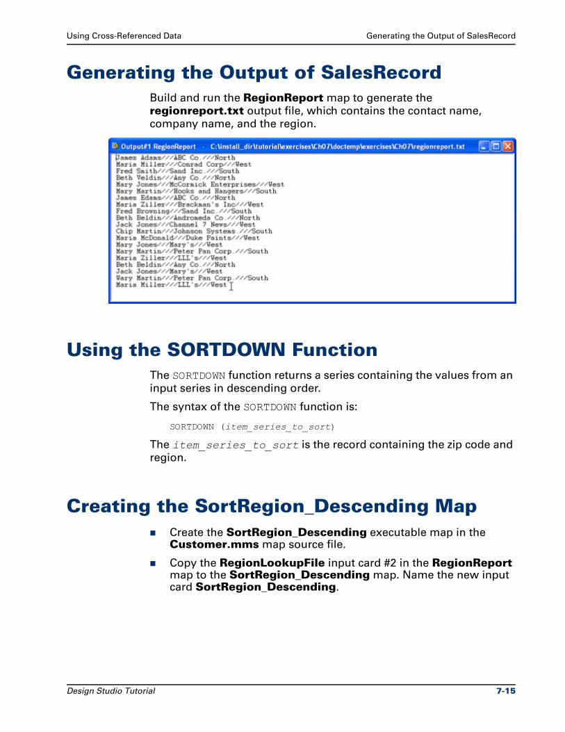
Using Cross-Referenced Data Generating the Output of SalesRecord
Generating the Output of SalesRecordBuild and run the RegionReport map to generate the
regionreport.txt output file, which contains the contact name,
company name, and the region.
Using the SORTDOWN FunctionThe SORTDOWN function returns a series containing the values from an
input series in descending order.
The syntax of the SORTDOWN function is:
SORTDOWN (item_series_to_sort)
The item_series_to_sort is the record containing the zip code and
region.
Creating the SortRegion_Descending MapCreate the SortRegion_Descending executable map in the Customer.mms map source file.
Copy the RegionLookupFile input card #2 in the RegionReport map to the SortRegion_Descending map. Name the new input card SortRegion_Descending.
Design Studio Tutorial 7-15
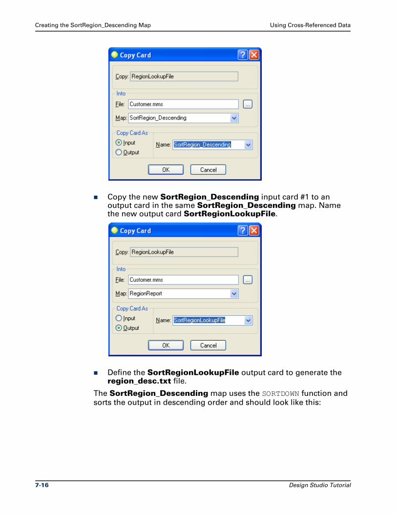
Creating the SortRegion_Descending Map Using Cross-Referenced Data
Copy the new SortRegion_Descending input card #1 to an output card in the same SortRegion_Descending map. Name the new output card SortRegionLookupFile.
Define the SortRegionLookupFile output card to generate the region_desc.txt file.
The SortRegion_Descending map uses the SORTDOWN function and
sorts the output in descending order and should look like this:
7-16 Design Studio Tutorial
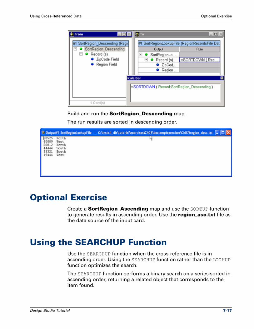
Using Cross-Referenced Data Optional Exercise
Build and run the SortRegion_Descending map.
The run results are sorted in descending order.
Optional ExerciseCreate a SortRegion_Ascending map and use the SORTUP function
to generate results in ascending order. Use the region_asc.txt file as
the data source of the input card.
Using the SEARCHUP FunctionUse the SEARCHUP function when the cross-reference file is in
ascending order. Using the SEARCHUP function rather than the LOOKUP
function optimizes the search.
The SEARCHUP function performs a binary search on a series sorted in
ascending order, returning a related object that corresponds to the
item found.
Design Studio Tutorial 7-17
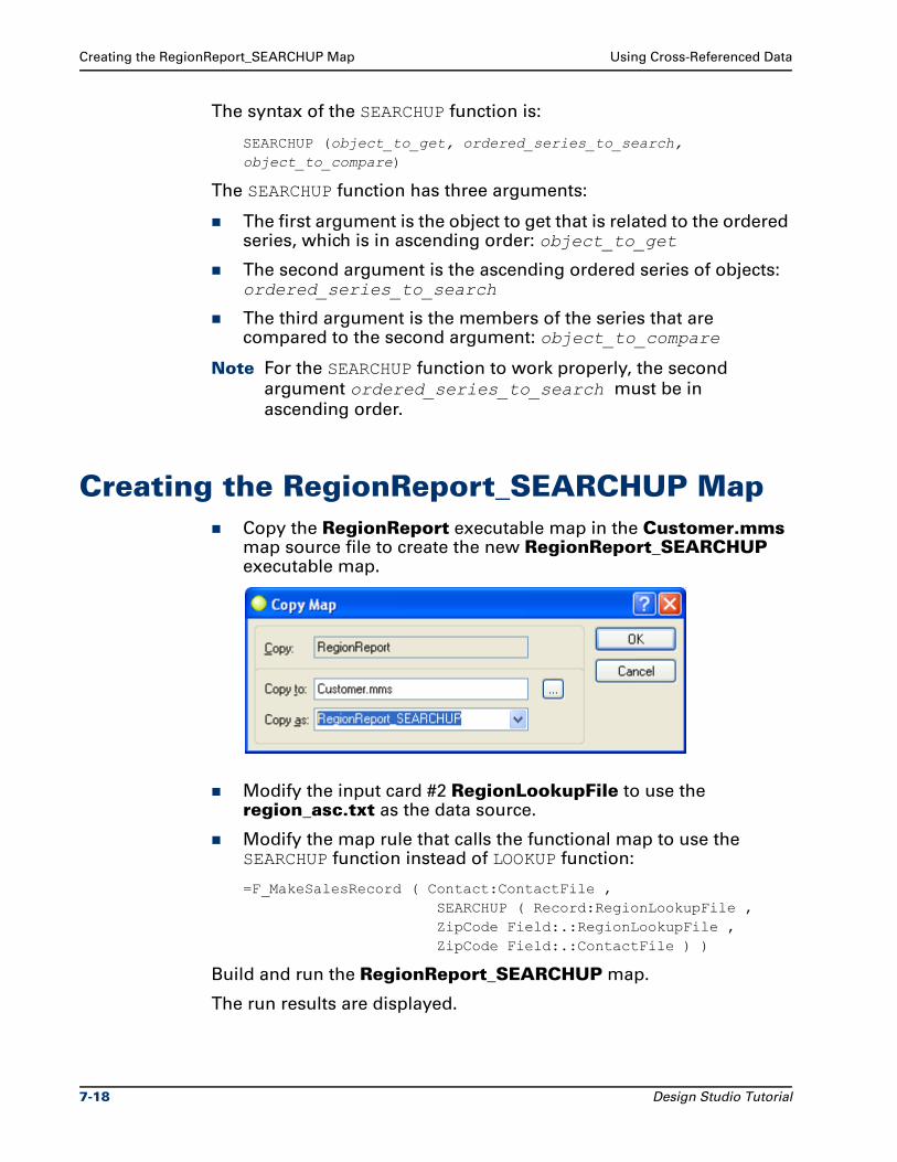
Creating the RegionReport_SEARCHUP Map Using Cross-Referenced Data
The syntax of the SEARCHUP function is:
SEARCHUP (object_to_get, ordered_series_to_search, object_to_compare)
The SEARCHUP function has three arguments:
The first argument is the object to get that is related to the ordered series, which is in ascending order: object_to_get
The second argument is the ascending ordered series of objects: ordered_series_to_search
The third argument is the members of the series that are compared to the second argument: object_to_compare
Note For the SEARCHUP function to work properly, the second
argument ordered_series_to_search must be in
ascending order.
Creating the RegionReport_SEARCHUP MapCopy the RegionReport executable map in the Customer.mms map source file to create the new RegionReport_SEARCHUP executable map.
Modify the input card #2 RegionLookupFile to use the region_asc.txt as the data source.
Modify the map rule that calls the functional map to use the SEARCHUP function instead of LOOKUP function:
=F_MakeSalesRecord ( Contact:ContactFile , SEARCHUP ( Record:RegionLookupFile , ZipCode Field:.:RegionLookupFile , ZipCode Field:.:ContactFile ) )
Build and run the RegionReport_SEARCHUP map.
The run results are displayed.
7-18 Design Studio Tutorial
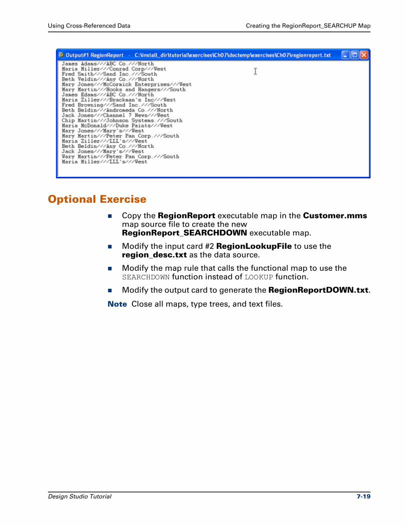
Using Cross-Referenced Data Creating the RegionReport_SEARCHUP Map
Optional ExerciseCopy the RegionReport executable map in the Customer.mms map source file to create the new RegionReport_SEARCHDOWN executable map.
Modify the input card #2 RegionLookupFile to use the region_desc.txt as the data source.
Modify the map rule that calls the functional map to use the SEARCHDOWN function instead of LOOKUP function.
Modify the output card to generate the RegionReportDOWN.txt.
Note Close all maps, type trees, and text files.
Design Studio Tutorial 7-19

Creating the RegionReport_SEARCHUP Map Using Cross-Referenced Data
7-20 Design Studio Tutorial
8Using the CHOOSE Function
This chapter explains how to decide which function to use when
cross-referencing data, and how to use that function. A map example
using each of these functions is provided.
ObjectivesThis chapter defines how to locate an object in a certain position in a
series.
By completing the exercises for Chapter 8, you will learn how to:
Use the CHOOSE function to locate an object in a certain position in a series.
Files Used in This ChapterYou will be working in the ..\tutorial\my_exercises\ch08 folder.
Files Provided for Chapter 8The following table describes the files provided for this chapter. Use
the files provided in Ch08.exe.
Icon File type Name Description
Text file prizes.txt Input data file containing a list of the prizes for each place
Design Studio Tutorial 8-1
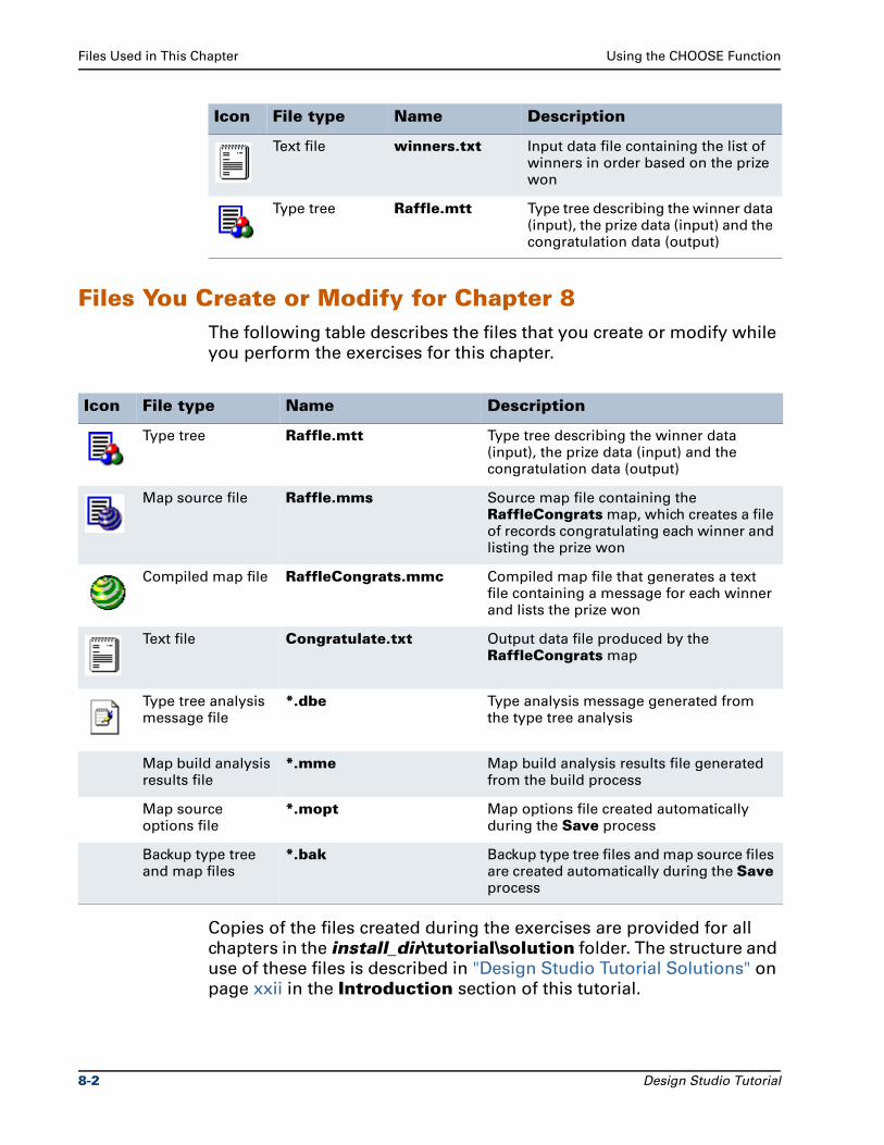
Files Used in This Chapter Using the CHOOSE Function
Files You Create or Modify for Chapter 8The following table describes the files that you create or modify while
you perform the exercises for this chapter.
Copies of the files created during the exercises are provided for all
chapters in the install_dir\tutorial\solution folder. The structure and
use of these files is described in "Design Studio Tutorial Solutions" on
page xxii in the Introduction section of this tutorial.
Text file winners.txt Input data file containing the list of winners in order based on the prize won
Type tree Raffle.mtt Type tree describing the winner data (input), the prize data (input) and the congratulation data (output)
Icon File type Name Description
Icon File type Name Description
Type tree Raffle.mtt Type tree describing the winner data (input), the prize data (input) and the congratulation data (output)
Map source file Raffle.mms Source map file containing the RaffleCongrats map, which creates a file of records congratulating each winner and listing the prize won
Compiled map file RaffleCongrats.mmc Compiled map file that generates a text file containing a message for each winner and lists the prize won
Text file Congratulate.txt Output data file produced by the RaffleCongrats map
Type tree analysis message file
*.dbe Type analysis message generated from the type tree analysis
Map build analysis results file
*.mme Map build analysis results file generated from the build process
Map source options file
*.mopt Map options file created automatically during the Save process
Backup type tree and map files
*.bak Backup type tree files and map source files are created automatically during the Save process
8-2 Design Studio Tutorial
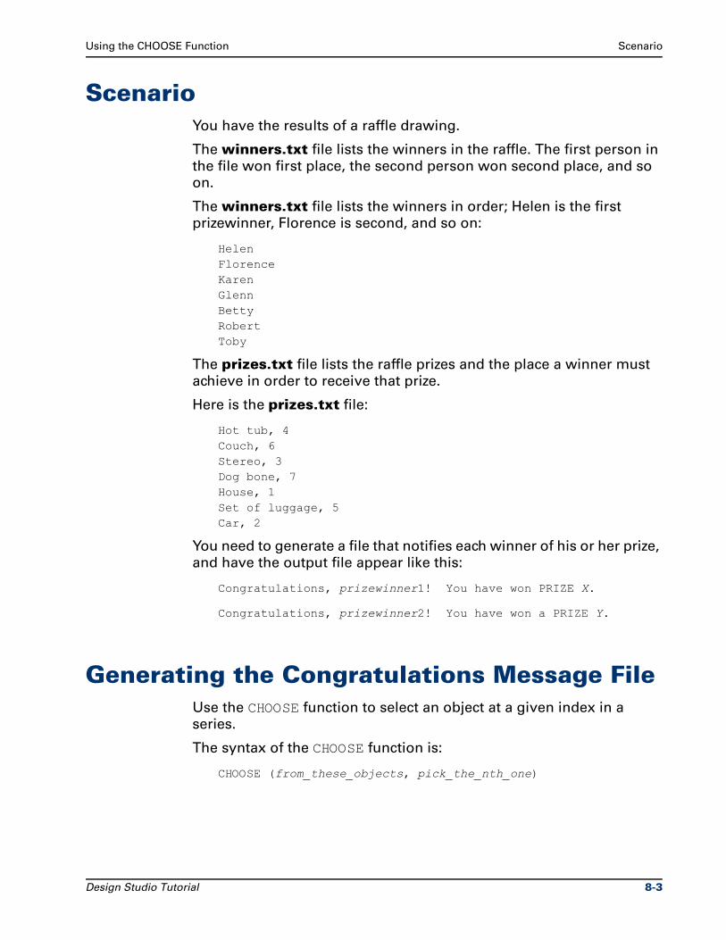
Using the CHOOSE Function Scenario
ScenarioYou have the results of a raffle drawing.
The winners.txt file lists the winners in the raffle. The first person in
the file won first place, the second person won second place, and so
on.
The winners.txt file lists the winners in order; Helen is the first
prizewinner, Florence is second, and so on:
HelenFlorenceKarenGlennBettyRobertToby
The prizes.txt file lists the raffle prizes and the place a winner must
achieve in order to receive that prize.
Here is the prizes.txt file:
Hot tub, 4Couch, 6Stereo, 3Dog bone, 7House, 1Set of luggage, 5Car, 2
You need to generate a file that notifies each winner of his or her prize,
and have the output file appear like this:
Congratulations, prizewinner1! You have won PRIZE X.
Congratulations, prizewinner2! You have won a PRIZE Y.
Generating the Congratulations Message FileUse the CHOOSE function to select an object at a given index in a
series.
The syntax of the CHOOSE function is:
CHOOSE (from_these_objects, pick_the_nth_one)
Design Studio Tutorial 8-3
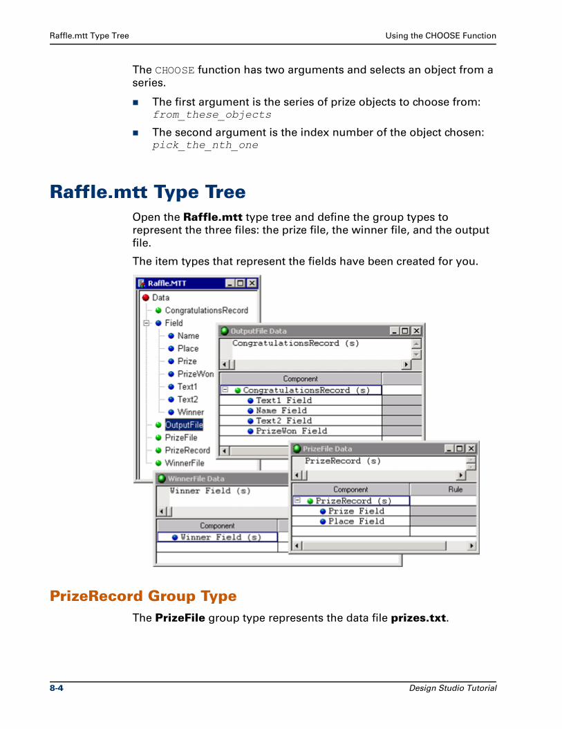
Raffle.mtt Type Tree Using the CHOOSE Function
The CHOOSE function has two arguments and selects an object from a
series.
The first argument is the series of prize objects to choose from: from_these_objects
The second argument is the index number of the object chosen: pick_the_nth_one
Raffle.mtt Type TreeOpen the Raffle.mtt type tree and define the group types to
represent the three files: the prize file, the winner file, and the output
file.
The item types that represent the fields have been created for you.
PrizeRecord Group TypeThe PrizeFile group type represents the data file prizes.txt.
8-4 Design Studio Tutorial
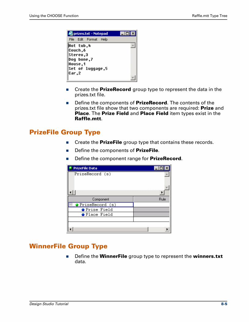
Using the CHOOSE Function Raffle.mtt Type Tree
Create the PrizeRecord group type to represent the data in the prizes.txt file.
Define the components of PrizeRecord. The contents of the prizes.txt file show that two components are required: Prize and Place. The Prize Field and Place Field item types exist in the Raffle.mtt.
PrizeFile Group TypeCreate the PrizeFile group type that contains these records.
Define the components of PrizeFile.
Define the component range for PrizeRecord.
WinnerFile Group TypeDefine the WinnerFile group type to represent the winners.txt data.
Design Studio Tutorial 8-5
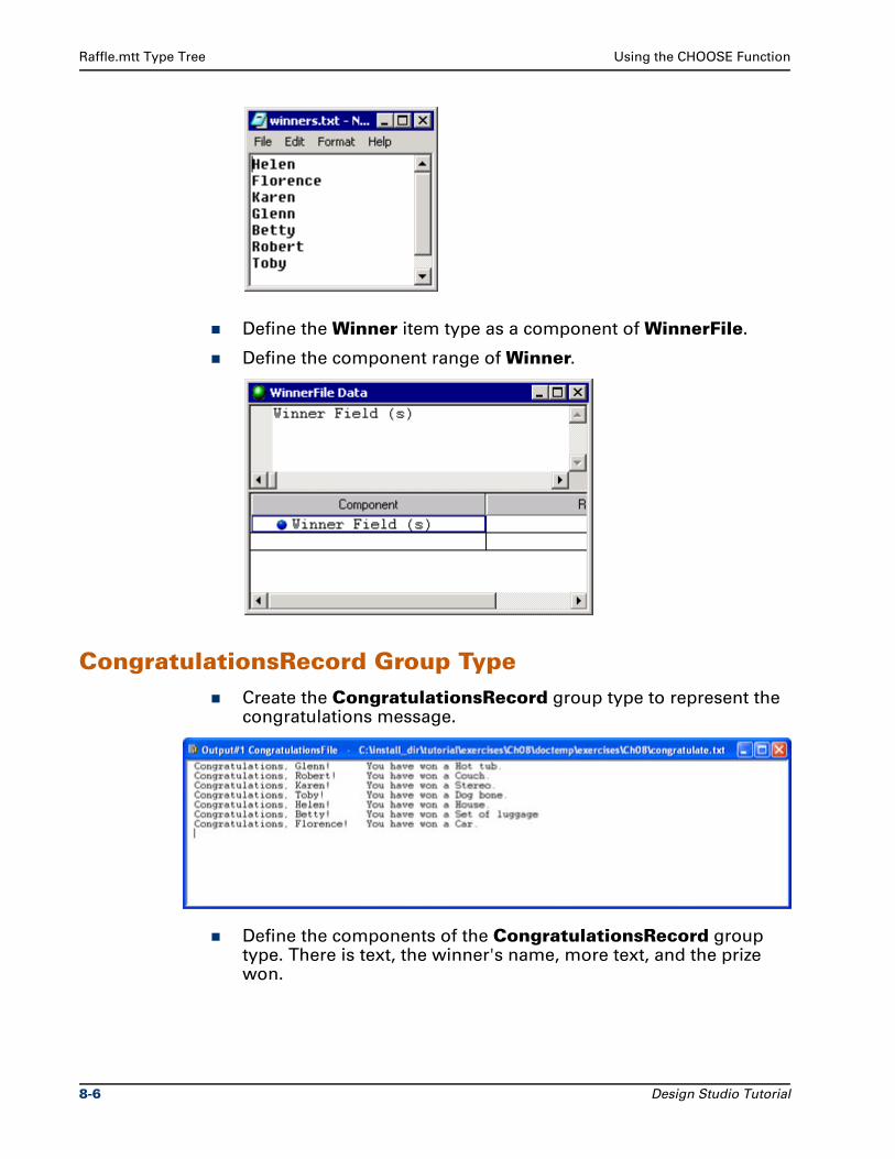
Raffle.mtt Type Tree Using the CHOOSE Function
Define the Winner item type as a component of WinnerFile.
Define the component range of Winner.
CongratulationsRecord Group TypeCreate the CongratulationsRecord group type to represent the congratulations message.
Define the components of the CongratulationsRecord group type. There is text, the winner's name, more text, and the prize won.
8-6 Design Studio Tutorial
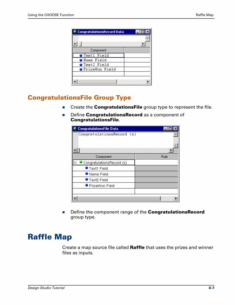
Using the CHOOSE Function Raffle Map
CongratulationsFile Group TypeCreate the CongratulationsFile group type to represent the file.
Define CongratulationsRecord as a component of CongratulationsFile.
Define the component range of the CongratulationsRecord group type.
Raffle Map Create a map source file called Raffle that uses the prizes and winner
files as inputs.
Design Studio Tutorial 8-7
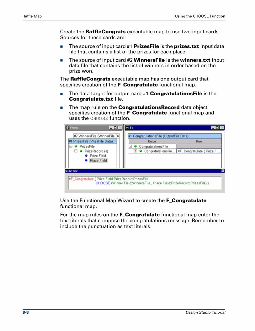
Raffle Map Using the CHOOSE Function
Create the RaffleCongrats executable map to use two input cards.
Sources for these cards are:
The source of input card #1 PrizesFile is the prizes.txt input data file that contains a list of the prizes for each place.
The source of input card #2 WinnersFile is the winners.txt input data file that contains the list of winners in order based on the prize won.
The RaffleCongrats executable map has one output card that
specifies creation of the F_Congratulate functional map.
The data target for output card #1 CongratulationsFile is the Congratulate.txt file.
The map rule on the CongratulationsRecord data object specifies creation of the F_Congratulate functional map and uses the CHOOSE function.
Use the Functional Map Wizard to create the F_Congratulate
functional map.
For the map rules on the F_Congratulate functional map enter the
text literals that compose the congratulations message. Remember to
include the punctuation as text literals.
8-8 Design Studio Tutorial
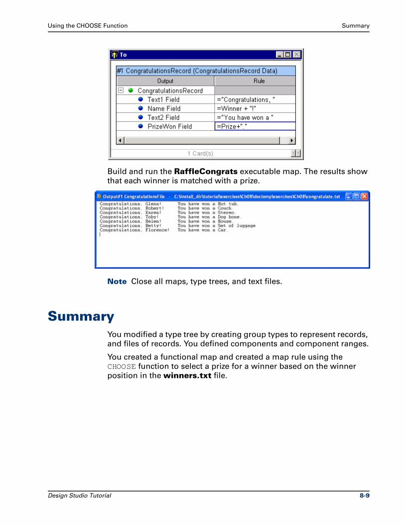
Using the CHOOSE Function Summary
Build and run the RaffleCongrats executable map. The results show
that each winner is matched with a prize.
Note Close all maps, type trees, and text files.
SummaryYou modified a type tree by creating group types to represent records,
and files of records. You defined components and component ranges.
You created a functional map and created a map rule using the
CHOOSE function to select a prize for a winner based on the winner
position in the winners.txt file.
Design Studio Tutorial 8-9

Summary Using the CHOOSE Function
8-10 Design Studio Tutorial

9Data Breaks By Object Count
Physical characteristics of data include delimiters and established
values of fixed length objects. These physical characteristics are used
to determine where data objects begin and end. If the data has
delimiters or is of a fixed length, these characteristics can be defined
in the type properties in the Type Designer. If data is not of fixed
length or it does not contain delimiters, other methods are required to
define a break in the data.
Breaks in data can be also determined when:
The count of a certain object reaches a specific value.
or
When the value of a certain item changes.
ObjectivesThis exercise uses the first method to define logical breaks in the data.
By completing the exercises for Chapter 9, you will learn how to:
Count objects to determine breaks in the data.
Dock or float the Rule Bar and Navigator window.
Create a new type tree using the Merge Type command.
Design Studio Tutorial 9-1
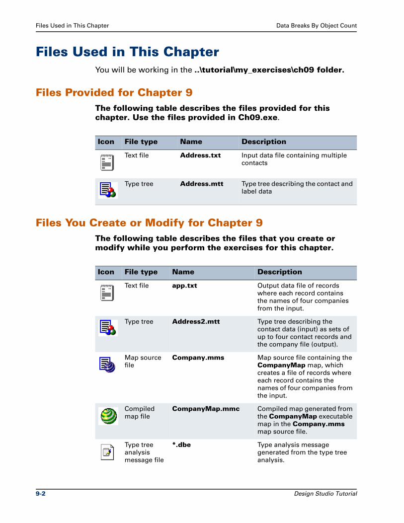
Files Used in This Chapter Data Breaks By Object Count
Files Used in This ChapterYou will be working in the ..\tutorial\my_exercises\ch09 folder.
Files Provided for Chapter 9The following table describes the files provided for this chapter. Use the files provided in Ch09.exe.
Files You Create or Modify for Chapter 9The following table describes the files that you create or modify while you perform the exercises for this chapter.
Icon File type Name Description
Text file Address.txt Input data file containing multiple contacts
Type tree Address.mtt Type tree describing the contact and label data
Icon File type Name Description
Text file app.txt Output data file of records where each record contains the names of four companies from the input.
Type tree Address2.mtt Type tree describing the contact data (input) as sets of up to four contact records and the company file (output).
Map source file
Company.mms Map source file containing the CompanyMap map, which creates a file of records where each record contains the names of four companies from the input.
Compiled map file
CompanyMap.mmc Compiled map generated from the CompanyMap executable map in the Company.mms map source file.
Type tree analysis message file
*.dbe Type analysis message generated from the type tree analysis.
9-2 Design Studio Tutorial
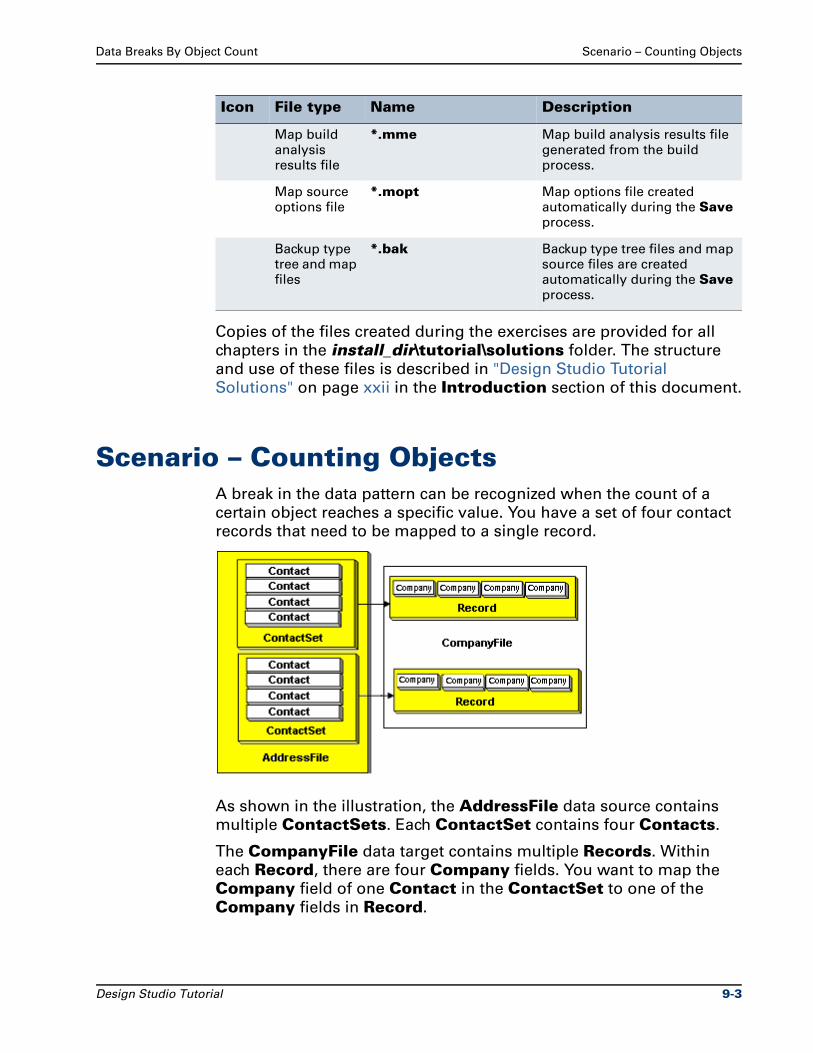
Data Breaks By Object Count Scenario – Counting Objects
Copies of the files created during the exercises are provided for all
chapters in the install_dir\tutorial\solutions folder. The structure
and use of these files is described in "Design Studio Tutorial
Solutions" on page xxii in the Introduction section of this document.
Scenario – Counting ObjectsA break in the data pattern can be recognized when the count of a
certain object reaches a specific value. You have a set of four contact
records that need to be mapped to a single record.
As shown in the illustration, the AddressFile data source contains
multiple ContactSets. Each ContactSet contains four Contacts.
The CompanyFile data target contains multiple Records. Within
each Record, there are four Company fields. You want to map the
Company field of one Contact in the ContactSet to one of the
Company fields in Record.
Map build analysis results file
*.mme Map build analysis results file generated from the build process.
Map source options file
*.mopt Map options file created automatically during the Save process.
Backup type tree and map files
*.bak Backup type tree files and map source files are created automatically during the Save process.
Icon File type Name Description
Design Studio Tutorial 9-3
Merging the Contact Group Type Data Breaks By Object Count
Define a specific number of data objects as a single data object. Use
the Type Designer to define the address file in terms of ContactSets,
and use a component rule on the Contact component of
ContactSet. Define the company file of records.
Use the Map Designer to create a map that maps the AddressFile to
the CompanyFile. Create a functional map to map a single
ContactSet to a single Record.
Defining a specific number of data objects as a single data object
enables each set of four contacts to be recognized as a single data
object. This allows you to map each set of four contacts to a single
record in the output.
Merging the Contact Group TypeIn the address.mtt type tree, merge the Contact group type to
create a new type tree. The components of the Contact group type
are copied as a function of the merge command.
Using the Merge Type command instead of the Copy Type
command excludes types that are not needed. This includes types
such as Label, LabelFile, and so on.
To merge the Contact group type to a new tree
1 Open the address.mtt type tree.
2 Create a new type tree called Address2.mtt and name the root Data.
3 Arrange the type tree windows so that both windows can be viewed.
9-4 Design Studio Tutorial
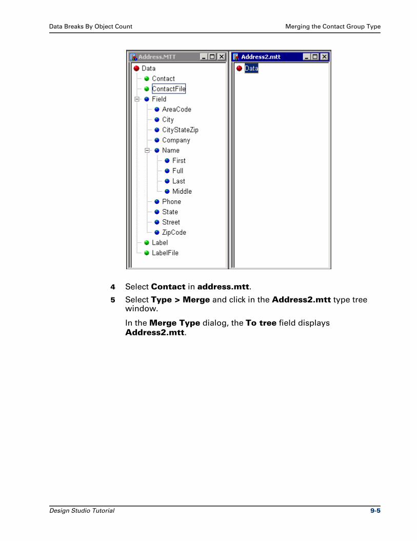
Data Breaks By Object Count Merging the Contact Group Type
4 Select Contact in address.mtt.
5 Select Type > Merge and click in the Address2.mtt type tree window.
In the Merge Type dialog, the To tree field displays
Address2.mtt.
Design Studio Tutorial 9-5
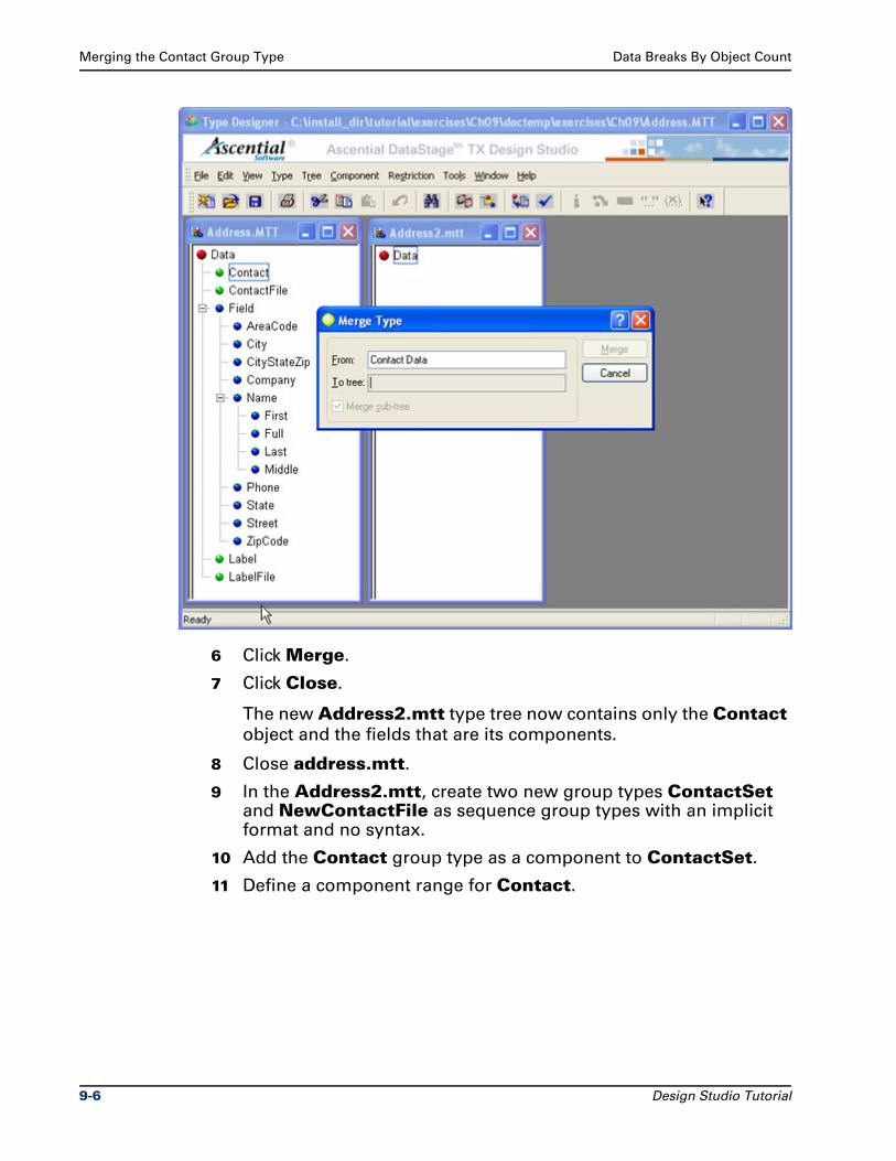
Merging the Contact Group Type Data Breaks By Object Count
6 Click Merge.
7 Click Close.
The new Address2.mtt type tree now contains only the Contact
object and the fields that are its components.
8 Close address.mtt.
9 In the Address2.mtt, create two new group types ContactSet and NewContactFile as sequence group types with an implicit format and no syntax.
10 Add the Contact group type as a component to ContactSet.
11 Define a component range for Contact.
9-6 Design Studio Tutorial
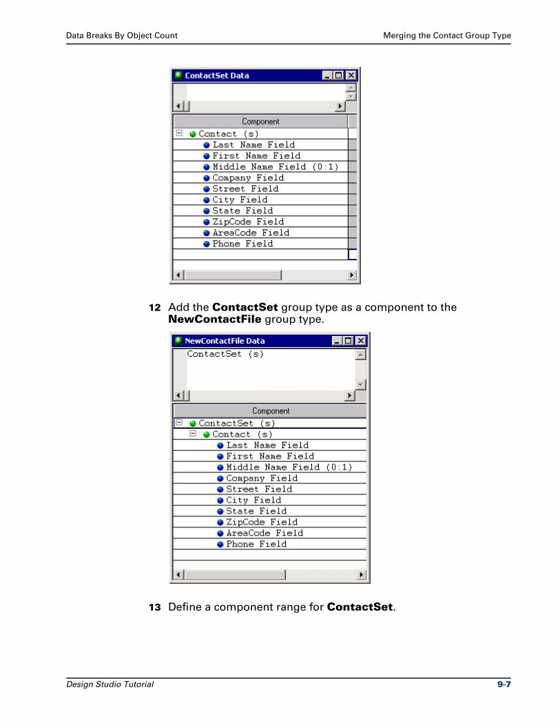
Data Breaks By Object Count Merging the Contact Group Type
12 Add the ContactSet group type as a component to the NewContactFile group type.
13 Define a component range for ContactSet.
Design Studio Tutorial 9-7
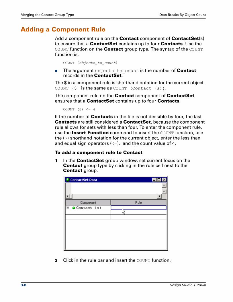
Merging the Contact Group Type Data Breaks By Object Count
Adding a Component RuleAdd a component rule on the Contact component of ContactSet(s)
to ensure that a ContactSet contains up to four Contacts. Use the
COUNT function on the Contact group type. The syntax of the COUNT
function is:
COUNT (objects_to_count)
The argument objects_to_count is the number of Contact records in the ContactSet.
The $ in a component rule is shorthand notation for the current object.
COUNT ($) is the same as COUNT (Contact (s)).
The component rule on the Contact component of ContactSet
ensures that a ContactSet contains up to four Contacts:
COUNT ($) <= 4
If the number of Contacts in the file is not divisible by four, the last
Contacts are still considered a ContactSet, because the component
rule allows for sets with less than four. To enter the component rule,
use the Insert Function command to insert the COUNT function, use
the ($) shorthand notation for the current object, enter the less than
and equal sign operators (<=), and the count value of 4.
To add a component rule to Contact
1 In the ContactSet group window, set current focus on the Contact group type by clicking in the rule cell next to the Contact group.
2 Click in the rule bar and insert the COUNT function.
9-8 Design Studio Tutorial
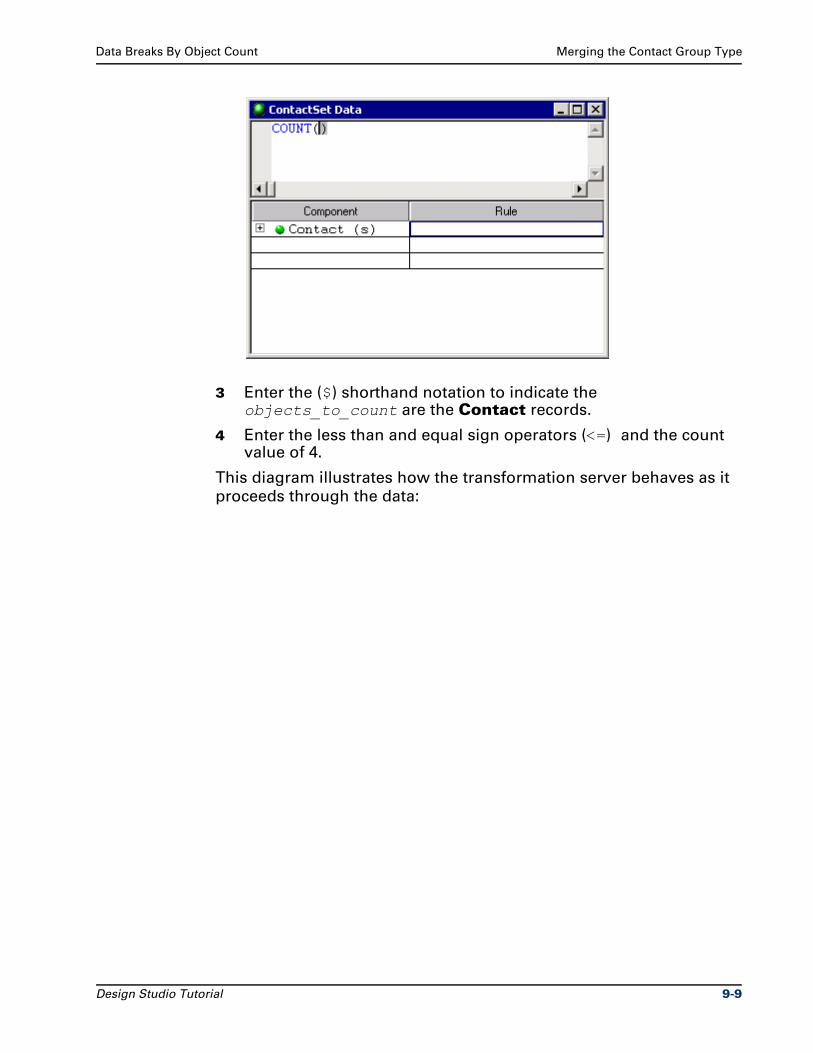
Data Breaks By Object Count Merging the Contact Group Type
3 Enter the ($) shorthand notation to indicate the objects_to_count are the Contact records.
4 Enter the less than and equal sign operators (<=) and the count value of 4.
This diagram illustrates how the transformation server behaves as it
proceeds through the data:
Design Studio Tutorial 9-9
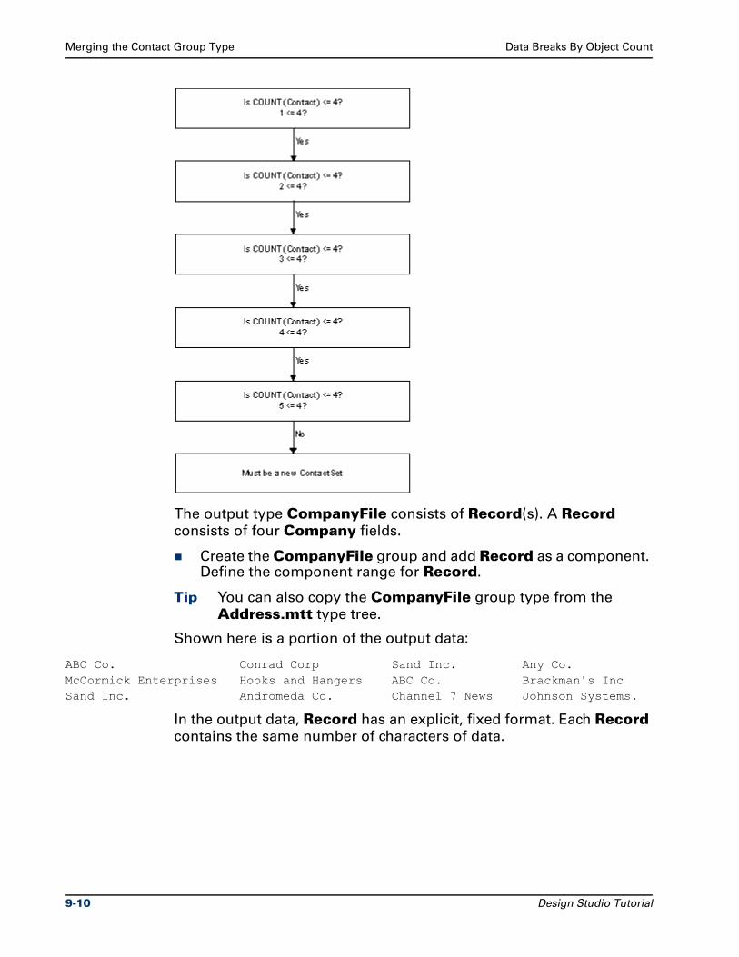
Merging the Contact Group Type Data Breaks By Object Count
The output type CompanyFile consists of Record(s). A Record
consists of four Company fields.
Create the CompanyFile group and add Record as a component. Define the component range for Record.
Tip You can also copy the CompanyFile group type from the
Address.mtt type tree.
Shown here is a portion of the output data:
ABC Co. Conrad Corp Sand Inc. Any Co.McCormick Enterprises Hooks and Hangers ABC Co. Brackman's IncSand Inc. Andromeda Co. Channel 7 News Johnson Systems.
In the output data, Record has an explicit, fixed format. Each Record
contains the same number of characters of data.
9-10 Design Studio Tutorial
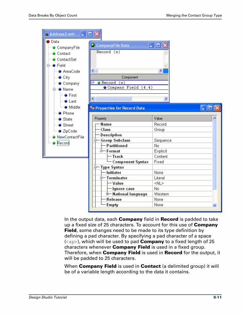
Data Breaks By Object Count Merging the Contact Group Type
In the output data, each Company field in Record is padded to take
up a fixed size of 25 characters. To account for this use of Company
Field, some changes need to be made to its type definition by
defining a pad character. By specifying a pad character of a space
(<sp>), which will be used to pad Company to a fixed length of 25
characters whenever Company Field is used in a fixed group.
Therefore, when Company Field is used in Record for the output, it
will be padded to 25 characters.
When Company Field is used in Contact (a delimited group) it will
be of a variable length according to the data it contains.
Design Studio Tutorial 9-11
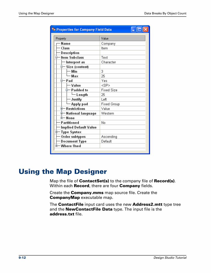
Using the Map Designer Data Breaks By Object Count
Using the Map DesignerMap the file of ContactSet(s) to the company file of Record(s). Within each Record, there are four Company fields.
Create the Company.mms map source file. Create the
CompanyMap executable map.
The ContactFile input card uses the new Address2.mtt type tree
and the NewContactFile Data type. The input file is the
address.txt file.
9-12 Design Studio Tutorial
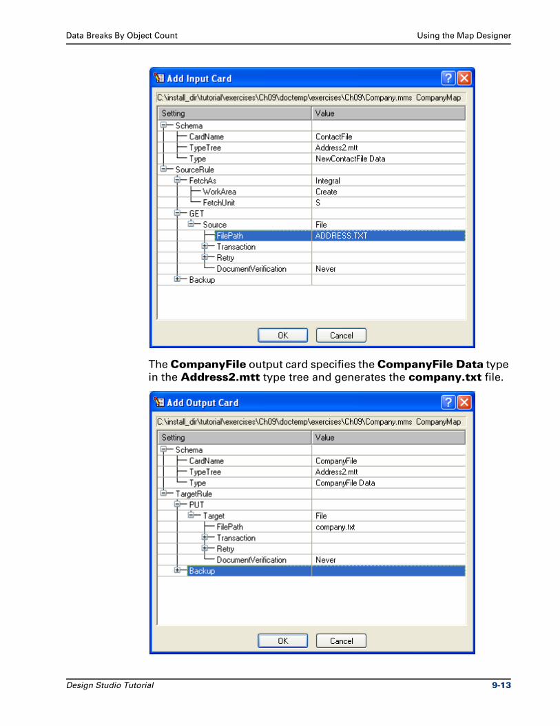
Data Breaks By Object Count Using the Map Designer
The CompanyFile output card specifies the CompanyFile Data type
in the Address2.mtt type tree and generates the company.txt file.
Design Studio Tutorial 9-13
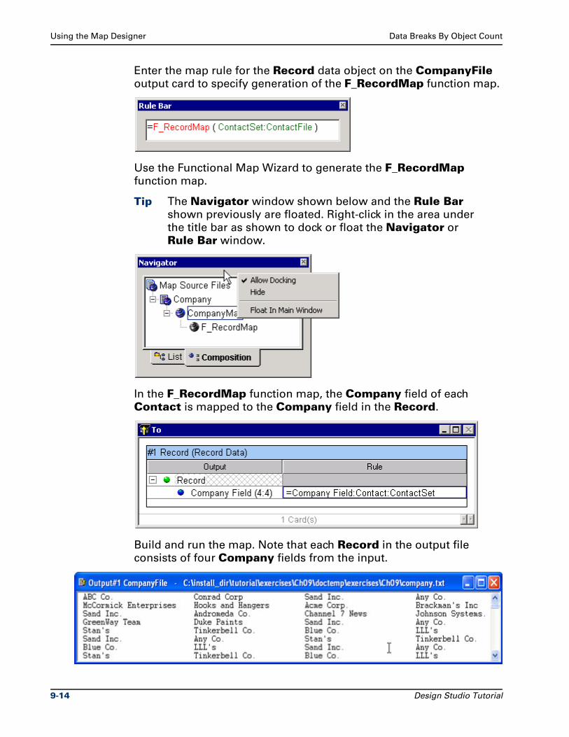
Using the Map Designer Data Breaks By Object Count
Enter the map rule for the Record data object on the CompanyFile
output card to specify generation of the F_RecordMap function map.
Use the Functional Map Wizard to generate the F_RecordMap
function map.
Tip The Navigator window shown below and the Rule Bar shown previously are floated. Right-click in the area under
the title bar as shown to dock or float the Navigator or
Rule Bar window.
In the F_RecordMap function map, the Company field of each
Contact is mapped to the Company field in the Record.
Build and run the map. Note that each Record in the output file
consists of four Company fields from the input.
9-14 Design Studio Tutorial

Data Breaks By Object Count Summary
Note Close all maps, type trees, and text files.
SummaryYou learned how to count objects to determine breaks in the data.
Design Studio Tutorial 9-15

Summary Data Breaks By Object Count
9-16 Design Studio Tutorial

10Data Breaks By Value
Breaks in data can be determined when the value of a certain item
changes.
A break in the data pattern can be recognized when the value of a
certain item type changes. This change in the value of a certain field
determines the end of one object and the beginning of the next object.
ObjectivesThe input file contains a specific number of purchase orders. You want
to generate a file that contains a field that gives the count of the
purchase orders in the input file.
By completing the exercises for Chapter 10, you will learn how to:
Determine if the value of a certain item changes to determine breaks in the data.
Identify and eliminate a type tree analysis error message about distinguishability by using a component rule to find the last record.
Use the COUNT function in a map rule to count the number of items in an input file.
Use the index value [LAST] in a component rule to refer to the last occurrence of that object.
Use $ shorthand notation in a component rule.
Design Studio Tutorial 10-1
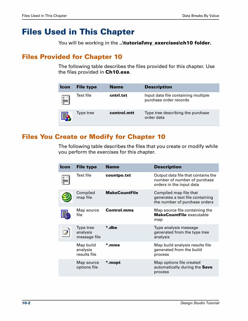
Files Used in This Chapter Data Breaks By Value
Files Used in This ChapterYou will be working in the ..\tutorial\my_exercises\ch10 folder.
Files Provided for Chapter 10The following table describes the files provided for this chapter. Use
the files provided in Ch10.exe.
Files You Create or Modify for Chapter 10The following table describes the files that you create or modify while
you perform the exercises for this chapter.
Icon File type Name Description
Text file cntrl.txt Input data file containing multiple purchase order records
Type tree control.mtt Type tree describing the purchase order data
Icon File type Name Description
Text file countpo.txt Output data file that contains the number of number of purchase orders in the input data
Compiled map file
MakeCountFile Compiled map file that generates a text file containing the number of purchase orders
Map source file
Control.mms Map source file containing the MakeCountFile executable map
Type tree analysis message file
*.dbe Type analysis message generated from the type tree analysis
Map build analysis results file
*.mme Map build analysis results file generated from the build process
Map source options file
*.mopt Map options file created automatically during the Save process
10-2 Design Studio Tutorial

Data Breaks By Value Scenario - Data Value Changes
Copies of the files created during the exercises are provided for all
chapters in the install_dir\tutorial\solutions folder. The structure
and use of these files is described in "Design Studio Tutorial
Solutions" on page xxii in the Introduction section of this document.
Scenario - Data Value ChangesIn a file of purchase orders, each purchase order (group type PO)
consists of line item records: one record per item. The PO number
appears at the beginning of each record. Therefore, the PO is a set of
consecutive line item records that have the same PO number.
In the data, each line item record contains a PO number (item type
PO#), a quantity (item type Quantity), item description (item type
Item), and price (item type Price) field:
12345 500 dress 065.99PO #1 12345 1000 pants 032.50
12345 300 suit 200.70PO #2 14478 275 pants 032.50
14478 500 suit 200.70
Control.mtt Type TreeThe Control.mtt type tree is not defined to recognize the
distinguishability of the PO data object.
Backup type tree and map files
*.bak Backup type tree files and map source files are created automatically during the Save process
Icon File type Name Description
Design Studio Tutorial 10-3
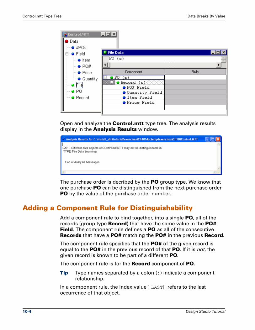
Control.mtt Type Tree Data Breaks By Value
Open and analyze the Control.mtt type tree. The analysis results
display in the Analysis Results window.
The purchase order is decribed by the PO group type. We know that
one purchase PO can be distinguished from the next purchase order
PO by the value of the purchase order number.
Adding a Component Rule for DistinguishabilityAdd a component rule to bind together, into a single PO, all of the
records (group type Record) that have the same value in the PO# Field. The component rule defines a PO as all of the consecutive
Records that have a PO# matching the PO# in the previous Record.
The component rule specifies that the PO# of the given record is
equal to the PO# in the previous record of that PO. If it is not, the
given record is known to be part of a different PO.
The component rule is for the Record component of PO.
Tip Type names separated by a colon (:) indicate a component
relationship.
In a component rule, the index value [LAST] refers to the last
occurrence of that object.
10-4 Design Studio Tutorial
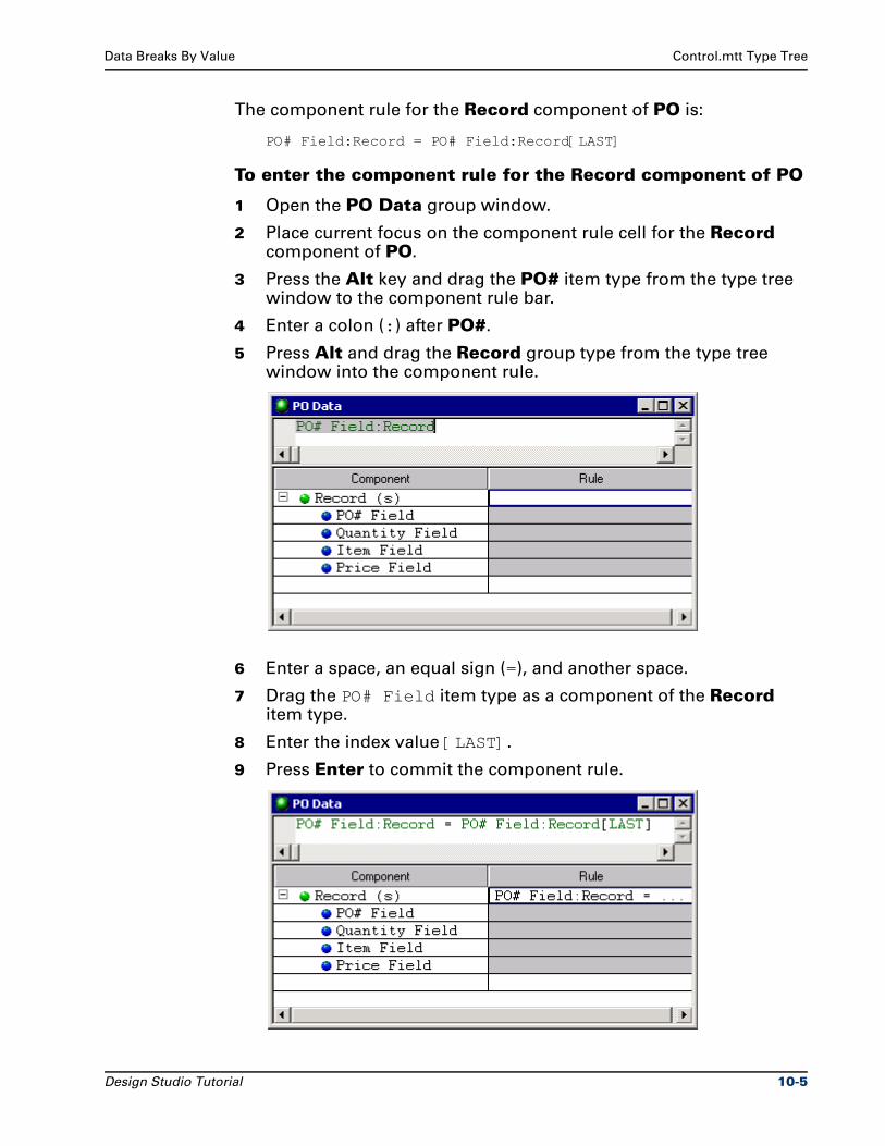
Data Breaks By Value Control.mtt Type Tree
The component rule for the Record component of PO is:
PO# Field:Record = PO# Field:Record[LAST]
To enter the component rule for the Record component of PO
1 Open the PO Data group window.
2 Place current focus on the component rule cell for the Record component of PO.
3 Press the Alt key and drag the PO# item type from the type tree window to the component rule bar.
4 Enter a colon (:) after PO#.
5 Press Alt and drag the Record group type from the type tree window into the component rule.
6 Enter a space, an equal sign (=), and another space.
7 Drag the PO# Field item type as a component of the Record item type.
8 Enter the index value [LAST].
9 Press Enter to commit the component rule.
Design Studio Tutorial 10-5
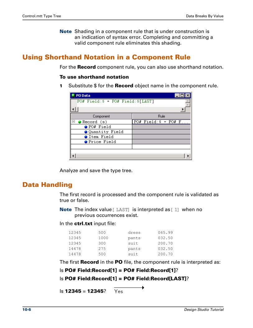
Control.mtt Type Tree Data Breaks By Value
Note Shading in a component rule that is under construction is
an indication of syntax error. Completing and committing a
valid component rule eliminates this shading.
Using Shorthand Notation in a Component RuleFor the Record component rule, you can also use shorthand notation.
To use shorthand notation
1 Substitute $ for the Record object name in the component rule.
Analyze and save the type tree.
Data HandlingThe first record is processed and the component rule is validated as
true or false.
Note The index value [LAST] is interpreted as [1] when no
previous occurrences exist.
In the ctrl.txt input file:
12345 500 dress 065.9912345 1000 pants 032.5012345 300 suit 200.7014478 275 pants 032.5014478 500 suit 200.70
The first Record in the PO file, the component rule is interpreted as:
Is PO# Field:Record[1] = PO# Field:Record[1]?
Is PO# Field:Record[1] = PO# Field:Record[LAST]?
Is 12345 = 12345?
10-6 Design Studio Tutorial
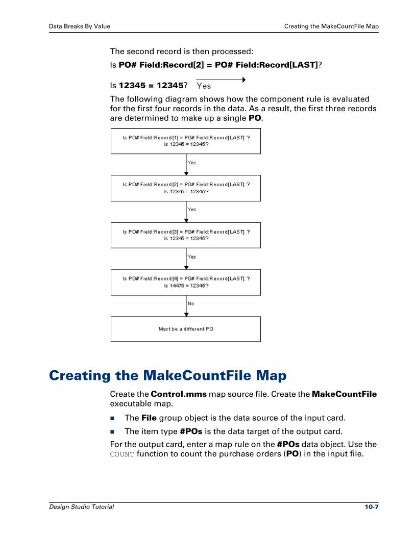
Data Breaks By Value Creating the MakeCountFile Map
The second record is then processed:
Is PO# Field:Record[2] = PO# Field:Record[LAST]?
Is 12345 = 12345?
The following diagram shows how the component rule is evaluated
for the first four records in the data. As a result, the first three records
are determined to make up a single PO.
Creating the MakeCountFile MapCreate the Control.mms map source file. Create the MakeCountFile
executable map.
The File group object is the data source of the input card.
The item type #POs is the data target of the output card.
For the output card, enter a map rule on the #POs data object. Use the
COUNT function to count the purchase orders (PO) in the input file.
Design Studio Tutorial 10-7
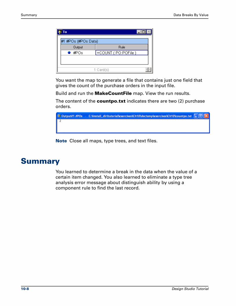
Summary Data Breaks By Value
You want the map to generate a file that contains just one field that
gives the count of the purchase orders in the input file.
Build and run the MakeCountFile map. View the run results.
The content of the countpo.txt indicates there are two (2) purchase
orders.
Note Close all maps, type trees, and text files.
SummaryYou learned to determine a break in the data when the value of a
certain item changed. You also learned to eliminate a type tree
analysis error message about distinguish ability by using a
component rule to find the last record.
10-8 Design Studio Tutorial
11Partitioning Types To Simplify Map
Rules
This chapter defines how to partition types to simplify map rules.
Partitioning is a method of subdividing data objects into mutually
exclusive subtypes. Data that can be divided into mutually exclusive
subtypes can be partitioned.
Partitioning is required when components are randomly or partially
ordered.
You may decide to use partitioning in a type tree to build additional
logic into the definition of the data. You may also use partitioning to
simplify the rules needed in your map.
ObjectivesThis exercise uses a single input file to generate multiple output files
using partitions and attributes.
By completing the exercises for Chapter 11, you will learn how to:
Partition to simplify map rules.
Identify partitions in map rules and component rules.
Use the identifier attribute to distinguish record types.
Generate multiple output files from a single input file.
Use the CURRENTDATE function.
View type properties in the Map Designer.
View component numbers in the group window.
Design Studio Tutorial 11-1
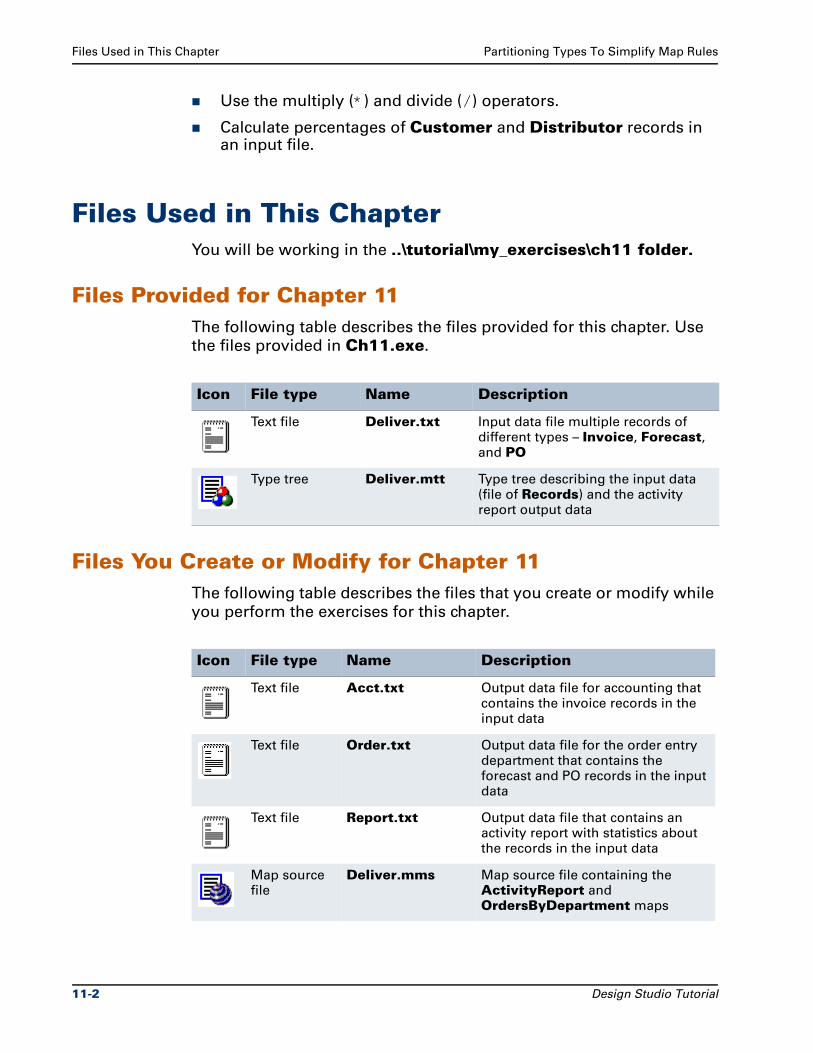
Files Used in This Chapter Partitioning Types To Simplify Map Rules
Use the multiply (*) and divide (/) operators.
Calculate percentages of Customer and Distributor records in an input file.
Files Used in This ChapterYou will be working in the ..\tutorial\my_exercises\ch11 folder.
Files Provided for Chapter 11The following table describes the files provided for this chapter. Use
the files provided in Ch11.exe.
Files You Create or Modify for Chapter 11The following table describes the files that you create or modify while
you perform the exercises for this chapter.
Icon File type Name Description
Text file Deliver.txt Input data file multiple records of different types – Invoice, Forecast, and PO
Type tree Deliver.mtt Type tree describing the input data (file of Records) and the activity report output data
Icon File type Name Description
Text file Acct.txt Output data file for accounting that contains the invoice records in the input data
Text file Order.txt Output data file for the order entry department that contains the forecast and PO records in the input data
Text file Report.txt Output data file that contains an activity report with statistics about the records in the input data
Map source file
Deliver.mms Map source file containing the ActivityReport and OrdersByDepartment maps
11-2 Design Studio Tutorial
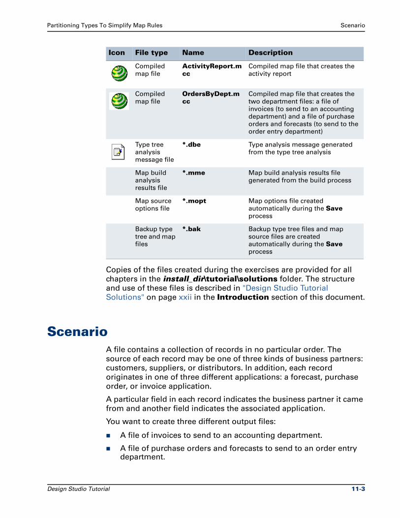
Partitioning Types To Simplify Map Rules Scenario
Copies of the files created during the exercises are provided for all
chapters in the install_dir\tutorial\solutions folder. The structure
and use of these files is described in "Design Studio Tutorial
Solutions" on page xxii in the Introduction section of this document.
ScenarioA file contains a collection of records in no particular order. The
source of each record may be one of three kinds of business partners:
customers, suppliers, or distributors. In addition, each record
originates in one of three different applications: a forecast, purchase
order, or invoice application.
A particular field in each record indicates the business partner it came
from and another field indicates the associated application.
You want to create three different output files:
A file of invoices to send to an accounting department.
A file of purchase orders and forecasts to send to an order entry department.
Compiled map file
ActivityReport.mcc
Compiled map file that creates the activity report
Compiled map file
OrdersByDept.mcc
Compiled map file that creates the two department files: a file of invoices (to send to an accounting department) and a file of purchase orders and forecasts (to send to the order entry department)
Type tree analysis message file
*.dbe Type analysis message generated from the type tree analysis
Map build analysis results file
*.mme Map build analysis results file generated from the build process
Map source options file
*.mopt Map options file created automatically during the Save process
Backup type tree and map files
*.bak Backup type tree files and map source files are created automatically during the Save process
Icon File type Name Description
Design Studio Tutorial 11-3
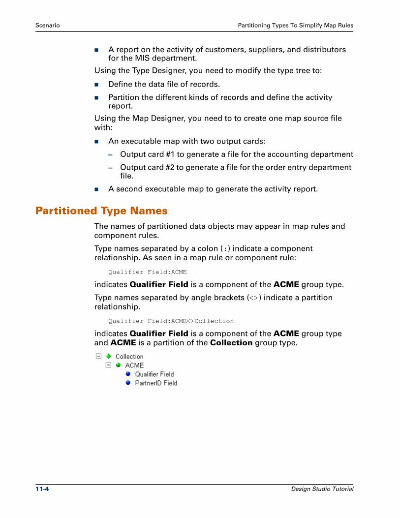
Scenario Partitioning Types To Simplify Map Rules
A report on the activity of customers, suppliers, and distributors for the MIS department.
Using the Type Designer, you need to modify the type tree to:
Define the data file of records.
Partition the different kinds of records and define the activity report.
Using the Map Designer, you need to to create one map source file
with:
An executable map with two output cards:
– Output card #1 to generate a file for the accounting department
– Output card #2 to generate a file for the order entry department file.
A second executable map to generate the activity report.
Partitioned Type NamesThe names of partitioned data objects may appear in map rules and
component rules.
Type names separated by a colon (:) indicate a component
relationship. As seen in a map rule or component rule:
Qualifier Field:ACME
indicates Qualifier Field is a component of the ACME group type.
Type names separated by angle brackets (<>) indicate a partition
relationship.
Qualifier Field:ACME<>Collection
indicates Qualifier Field is a component of the ACME group type
and ACME is a partition of the Collection group type.
11-4 Design Studio Tutorial
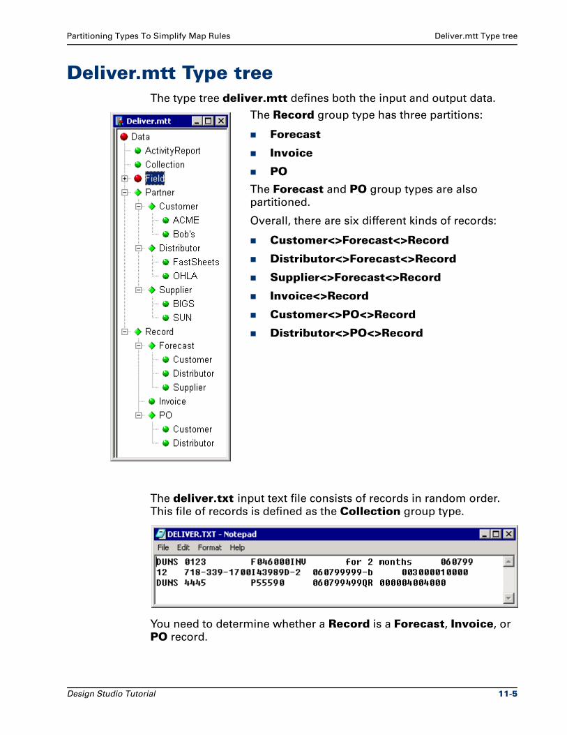
Partitioning Types To Simplify Map Rules Deliver.mtt Type tree
Deliver.mtt Type treeThe type tree deliver.mtt defines both the input and output data.
The deliver.txt input text file consists of records in random order.
This file of records is defined as the Collection group type.
You need to determine whether a Record is a Forecast, Invoice, or
PO record.
The Record group type has three partitions:
Forecast
Invoice
PO
The Forecast and PO group types are also
partitioned.
Overall, there are six different kinds of records:
Customer<>Forecast<>Record
Distributor<>Forecast<>Record
Supplier<>Forecast<>Record
Invoice<>Record
Customer<>PO<>Record
Distributor<>PO<>Record
Design Studio Tutorial 11-5
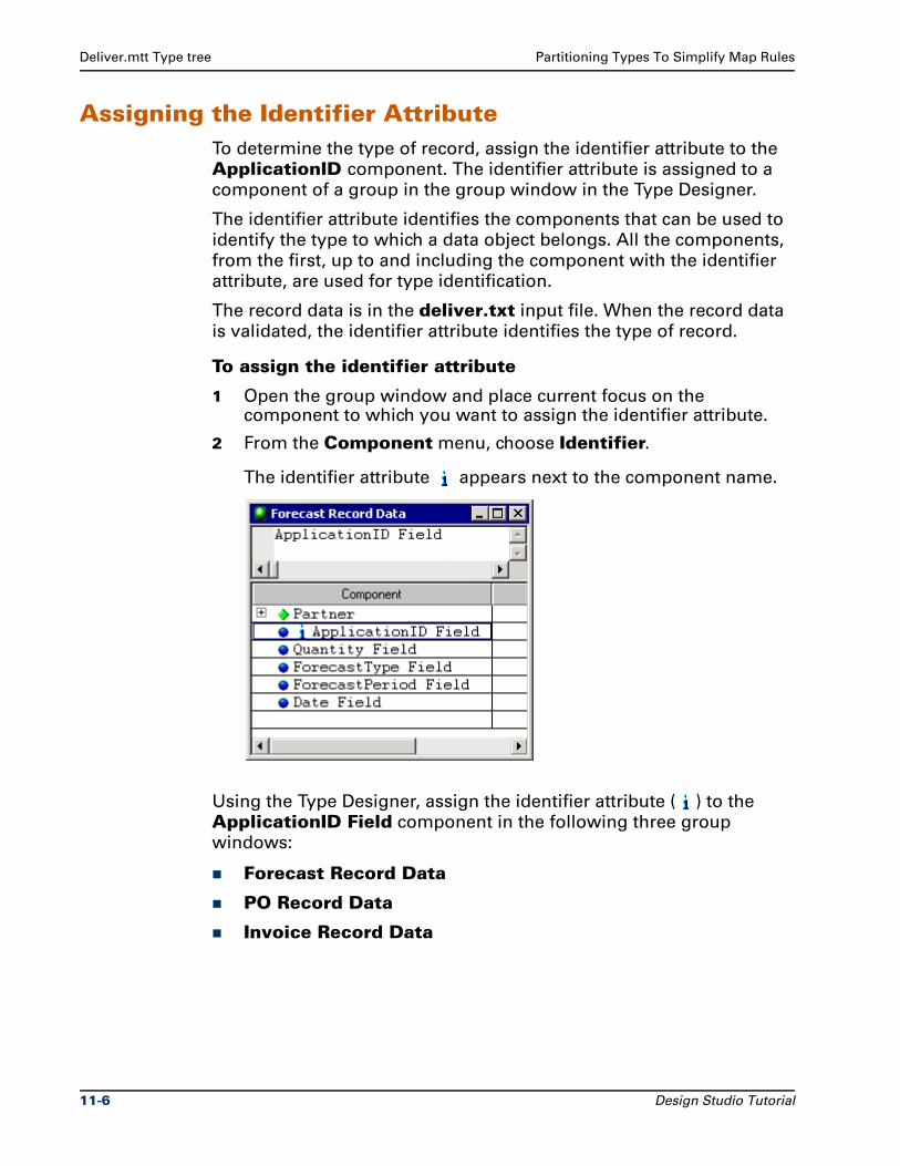
Deliver.mtt Type tree Partitioning Types To Simplify Map Rules
Assigning the Identifier AttributeTo determine the type of record, assign the identifier attribute to the
ApplicationID component. The identifier attribute is assigned to a
component of a group in the group window in the Type Designer.
The identifier attribute identifies the components that can be used to
identify the type to which a data object belongs. All the components,
from the first, up to and including the component with the identifier
attribute, are used for type identification.
The record data is in the deliver.txt input file. When the record data
is validated, the identifier attribute identifies the type of record.
To assign the identifier attribute
1 Open the group window and place current focus on the component to which you want to assign the identifier attribute.
2 From the Component menu, choose Identifier.
The identifier attribute appears next to the component name.
Using the Type Designer, assign the identifier attribute ( ) to the
ApplicationID Field component in the following three group
windows:
Forecast Record Data
PO Record Data
Invoice Record Data
11-6 Design Studio Tutorial
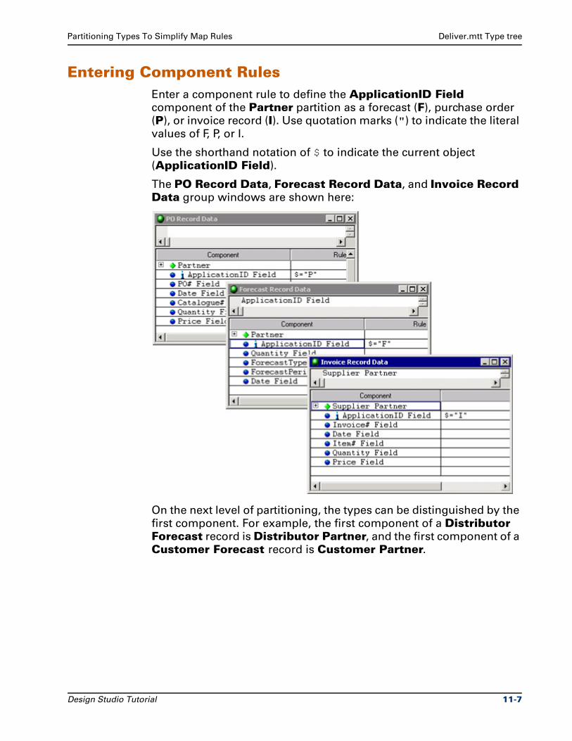
Partitioning Types To Simplify Map Rules Deliver.mtt Type tree
Entering Component RulesEnter a component rule to define the ApplicationID Field
component of the Partner partition as a forecast (F), purchase order
(P), or invoice record (I). Use quotation marks (") to indicate the literal
values of F, P, or I.
Use the shorthand notation of $ to indicate the current object
(ApplicationID Field).
The PO Record Data, Forecast Record Data, and Invoice Record Data group windows are shown here:
On the next level of partitioning, the types can be distinguished by the
first component. For example, the first component of a Distributor Forecast record is Distributor Partner, and the first component of a
Customer Forecast record is Customer Partner.
Design Studio Tutorial 11-7
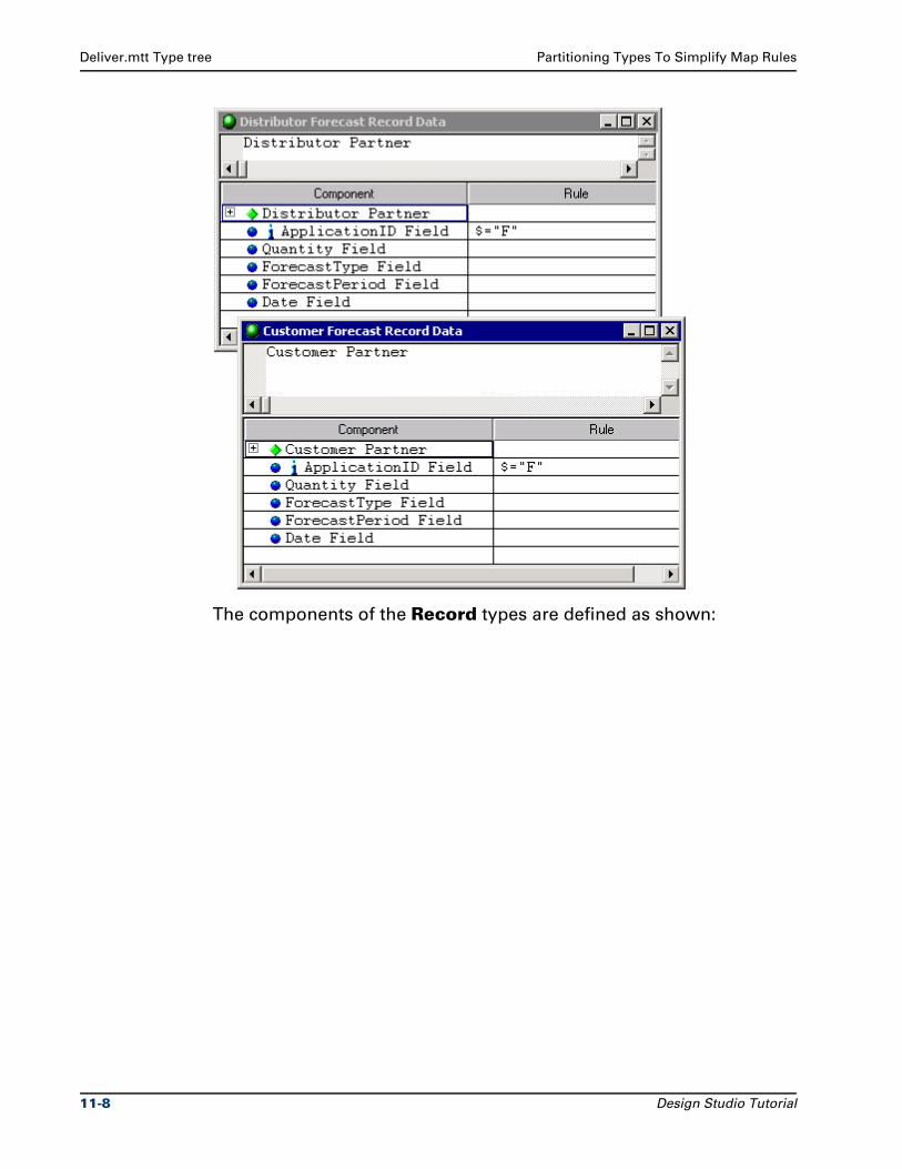
Deliver.mtt Type tree Partitioning Types To Simplify Map Rules
The components of the Record types are defined as shown:
11-8 Design Studio Tutorial
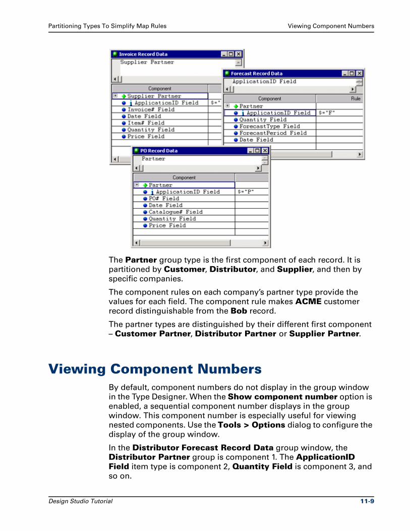
Partitioning Types To Simplify Map Rules Viewing Component Numbers
The Partner group type is the first component of each record. It is
partitioned by Customer, Distributor, and Supplier, and then by
specific companies.
The component rules on each company’s partner type provide the
values for each field. The component rule makes ACME customer
record distinguishable from the Bob record.
The partner types are distinguished by their different first component
– Customer Partner, Distributor Partner or Supplier Partner.
Viewing Component NumbersBy default, component numbers do not display in the group window
in the Type Designer. When the Show component number option is
enabled, a sequential component number displays in the group
window. This component number is especially useful for viewing
nested components. Use the Tools > Options dialog to configure the
display of the group window.
In the Distributor Forecast Record Data group window, the
Distributor Partner group is component 1. The ApplicationID Field item type is component 2, Quantity Field is component 3, and
so on.
Design Studio Tutorial 11-9
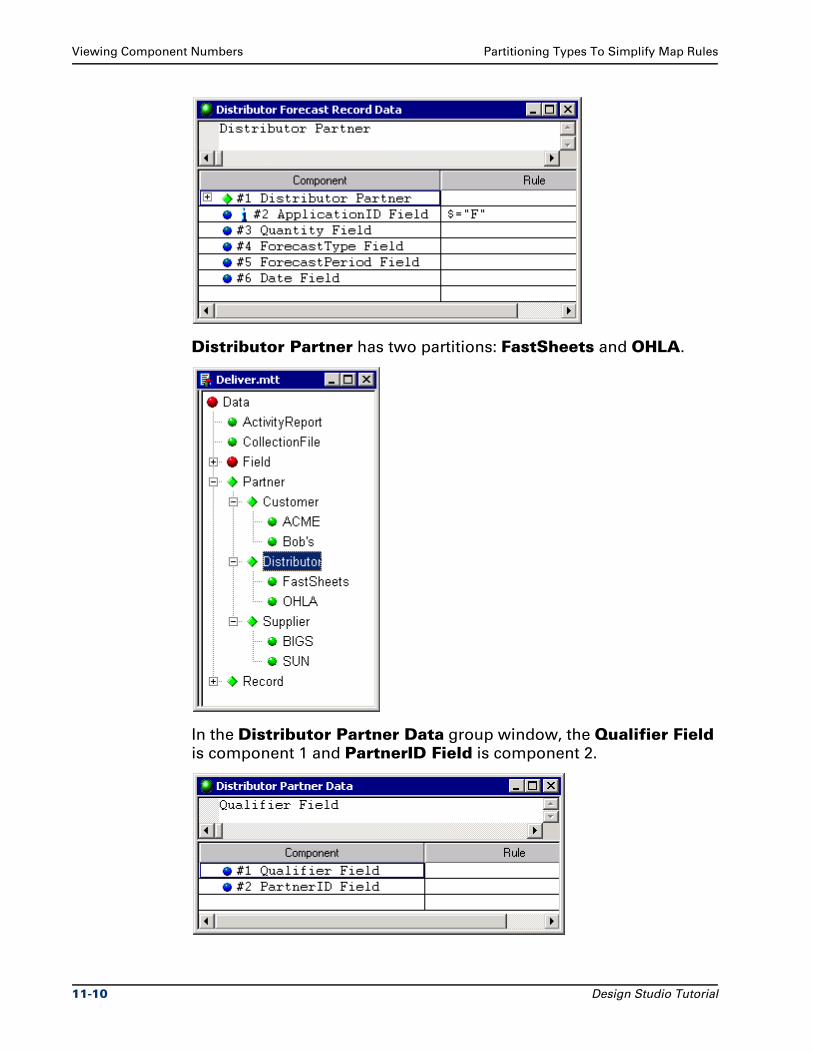
Viewing Component Numbers Partitioning Types To Simplify Map Rules
Distributor Partner has two partitions: FastSheets and OHLA.
In the Distributor Partner Data group window, the Qualifier Field
is component 1 and PartnerID Field is component 2.
11-10 Design Studio Tutorial
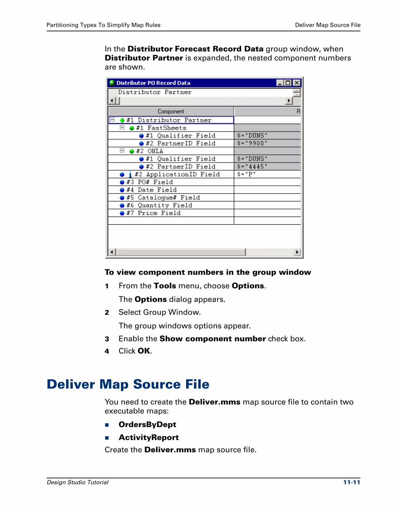
Partitioning Types To Simplify Map Rules Deliver Map Source File
In the Distributor Forecast Record Data group window, when
Distributor Partner is expanded, the nested component numbers
are shown.
To view component numbers in the group window
1 From the Tools menu, choose Options.
The Options dialog appears.
2 Select Group Window.
The group windows options appear.
3 Enable the Show component number check box.
4 Click OK.
Deliver Map Source FileYou need to create the Deliver.mms map source file to contain two
executable maps:
OrdersByDept
ActivityReport
Create the Deliver.mms map source file.
Design Studio Tutorial 11-11
Deliver Map Source File Partitioning Types To Simplify Map Rules
OrdersByDept Executable MapThe OrdersByDept map uses one data source (deliver.txt) and
generates two output files (acct.txt and order.txt).
Create the OrdersByDept map in the Deliver.mss map source file.
Use the Deliver.mtt type tree.
The input data source is the deliver.txt file. The data object that
represents this file is the CollectionFile group type.
You need two output cards to generate two output files:
The acct.txt text file for the accounting department.
The order.txt text for the order entry department.
Note Each input and output file is defined by the same
CollectionFile type in the Deliver.mtt type tree.
Generating the Acct.txt File
Name the first output card Accounting.
To generate the records in the Accounting output, map the Invoice
records from the input. The input Record is the same as the output
Record, which is partitioned.
Drag the Invoice type from the input card to the rule cell for Record on the output card.
11-12 Design Studio Tutorial
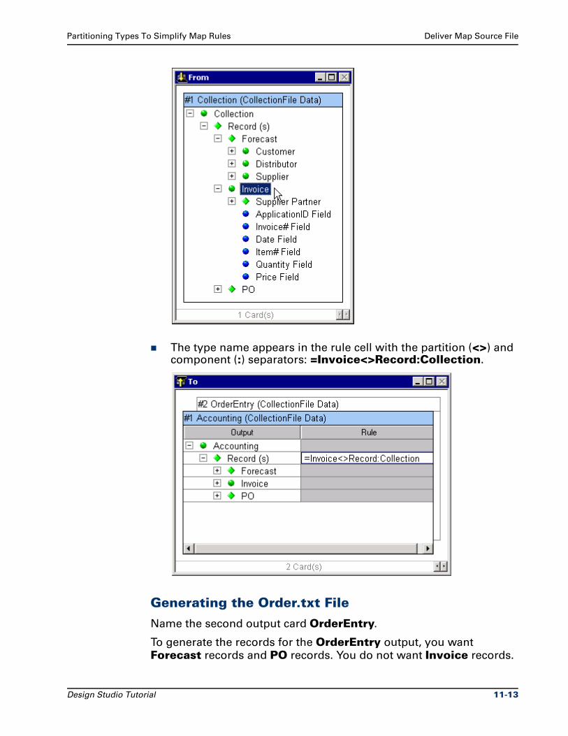
Partitioning Types To Simplify Map Rules Deliver Map Source File
The type name appears in the rule cell with the partition (<>) and component (:) separators: =Invoice<>Record:Collection.
Generating the Order.txt File
Name the second output card OrderEntry.
To generate the records for the OrderEntry output, you want
Forecast records and PO records. You do not want Invoice records.
Design Studio Tutorial 11-13
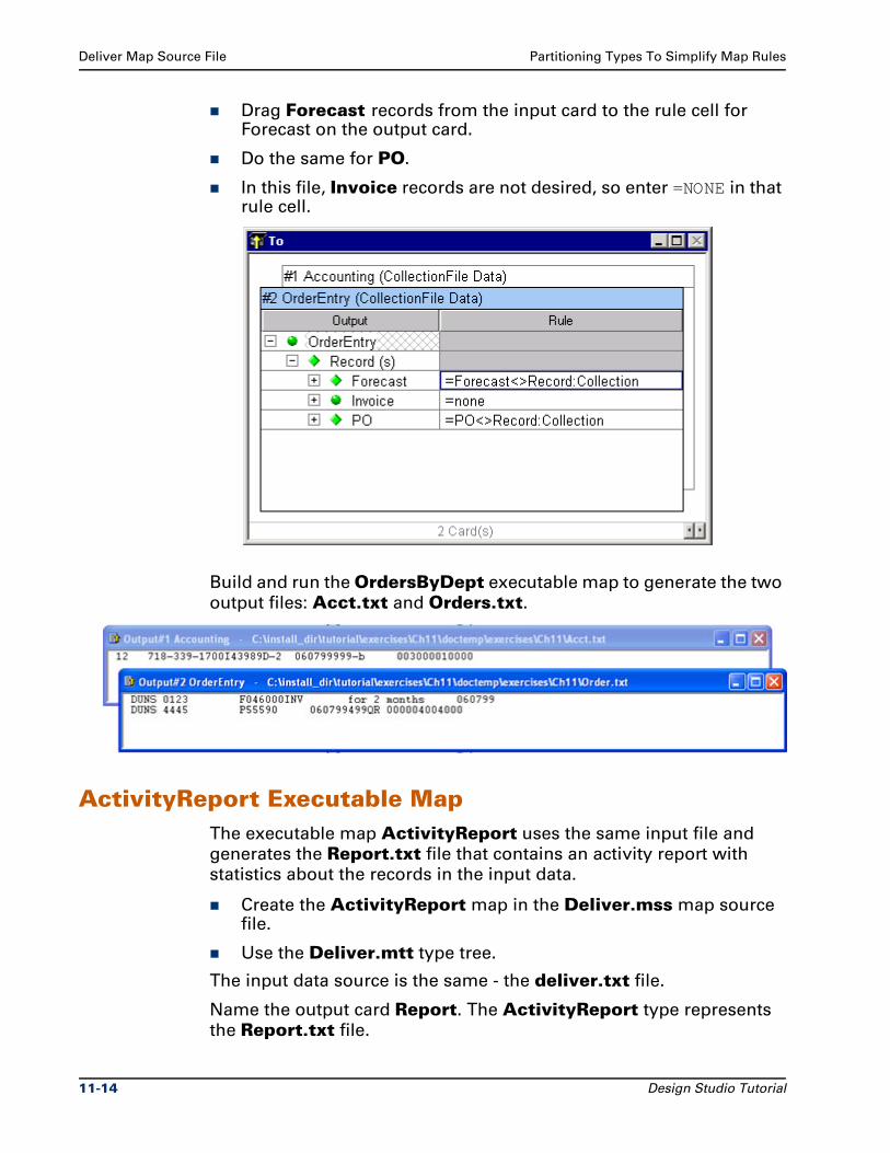
Deliver Map Source File Partitioning Types To Simplify Map Rules
Drag Forecast records from the input card to the rule cell for Forecast on the output card.
Do the same for PO.
In this file, Invoice records are not desired, so enter =NONE in that rule cell.
Build and run the OrdersByDept executable map to generate the two
output files: Acct.txt and Orders.txt.
ActivityReport Executable MapThe executable map ActivityReport uses the same input file and
generates the Report.txt file that contains an activity report with
statistics about the records in the input data.
Create the ActivityReport map in the Deliver.mss map source file.
Use the Deliver.mtt type tree.
The input data source is the same - the deliver.txt file.
Name the output card Report. The ActivityReport type represents
the Report.txt file.
11-14 Design Studio Tutorial
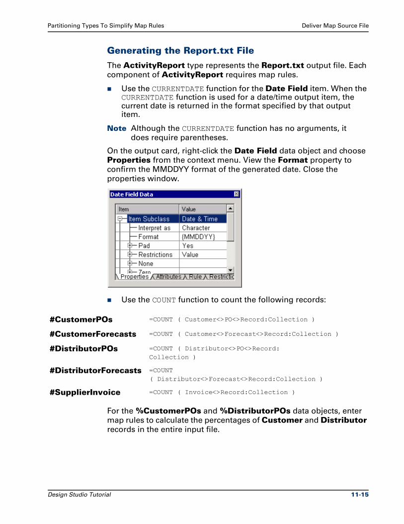
Partitioning Types To Simplify Map Rules Deliver Map Source File
Generating the Report.txt File
The ActivityReport type represents the Report.txt output file. Each
component of ActivityReport requires map rules.
Use the CURRENTDATE function for the Date Field item. When the CURRENTDATE function is used for a date/time output item, the current date is returned in the format specified by that output item.
Note Although the CURRENTDATE function has no arguments, it
does require parentheses.
On the output card, right-click the Date Field data object and choose
Properties from the context menu. View the Format property to
confirm the MMDDYY format of the generated date. Close the
properties window.
Use the COUNT function to count the following records:
For the %CustomerPOs and %DistributorPOs data objects, enter
map rules to calculate the percentages of Customer and Distributor
records in the entire input file.
#CustomerPOs =COUNT ( Customer<>PO<>Record:Collection )
#CustomerForecasts =COUNT ( Customer<>Forecast<>Record:Collection )
#DistributorPOs =COUNT ( Distributor<>PO<>Record:Collection )
#DistributorForecasts =COUNT( Distributor<>Forecast<>Record:Collection )
#SupplierInvoice =COUNT ( Invoice<>Record:Collection )
Design Studio Tutorial 11-15
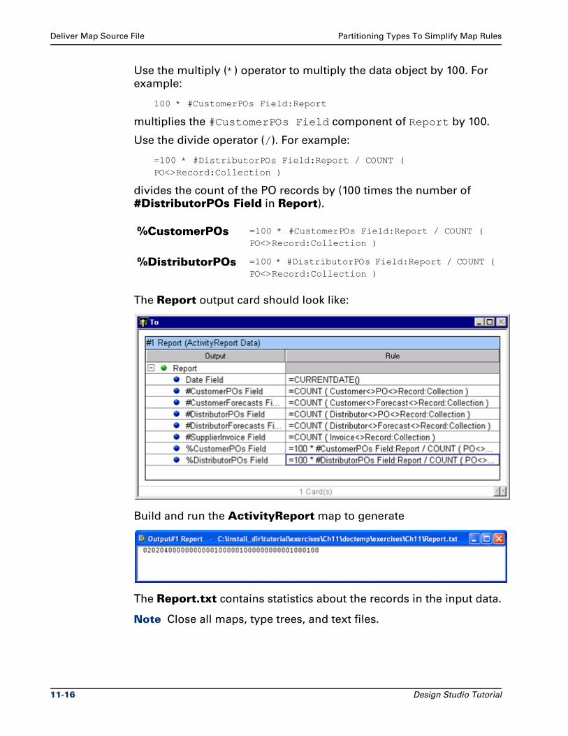
Deliver Map Source File Partitioning Types To Simplify Map Rules
Use the multiply (*) operator to multiply the data object by 100. For
example:
100 * #CustomerPOs Field:Report
multiplies the #CustomerPOs Field component of Report by 100.
Use the divide operator (/). For example:
=100 * #DistributorPOs Field:Report / COUNT ( PO<>Record:Collection )
divides the count of the PO records by (100 times the number of
#DistributorPOs Field in Report).
The Report output card should look like:
Build and run the ActivityReport map to generate
The Report.txt contains statistics about the records in the input data.
Note Close all maps, type trees, and text files.
%CustomerPOs =100 * #CustomerPOs Field:Report / COUNT ( PO<>Record:Collection )
%DistributorPOs =100 * #DistributorPOs Field:Report / COUNT ( PO<>Record:Collection )
11-16 Design Studio Tutorial
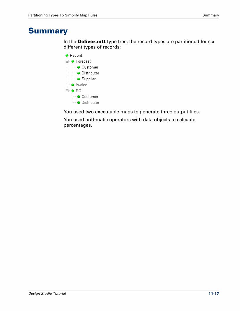
Partitioning Types To Simplify Map Rules Summary
SummaryIn the Deliver.mtt type tree, the record types are partitioned for six
different types of records:
You used two executable maps to generate three output files.
You used arithmatic operators with data objects to calcuate
percentages.
Design Studio Tutorial 11-17

Summary Partitioning Types To Simplify Map Rules
11-18 Design Studio Tutorial
12Mapping Optional Inputs
Some data objects are not always present in the input file.
ObjectivesThis exercise maps optional input data objects.
By completing the exercises for Chapter 12, you will learn how to:
Map optional inputs.
Use category types to organize related types.
Files Used in This ChapterYou will be working in the ..\tutorial\my_exercises\ch12 folder.
Files Provided for Chapter 12The following table describes the files provided for this chapter. Use
the files provided in Ch12.exe.
Icon File type Name Description
Text file Sts.txt Input data file containing weather and human statistics on states in the United States
Type tree States.mtt Type tree describing the input data (file of statistics by state) and the output data (file of state populations)
Design Studio Tutorial 12-1
Scenario Mapping Optional Inputs
Files You Create or Modify for Chapter 12The following table describes the files that you create or modify while
you perform the exercises for this chapter.
Copies of the files created during the exercises are provided for all
chapters in the install_dir\tutorial\solutions folder. The structure
and use of these files is described in "Design Studio Tutorial
Solutions" on page xxii in the Introduction section of this document.
ScenarioA data file of statistics on states in the United States may include
population density, median household income, average summer
temperature, average winter temperature, and average yearly rainfall.
You need to generate a file that contains only the population statistics.
Icon File type Name Description
Text file Output.txt Output data file that holds records for each state containing the state ID and the population for that state
Map source file
States.mms Map source file containing the Master map, which creates the state population file from the state statistics file
Compiled map file
States.mmc Compiled map file that generates the Output.txt file
Type tree analysis message file
*.dbe Type analysis message generated from the type tree analysis
Map build analysis results file
*.mme Map build analysis results file generated from the build process
Map source options file
*.mopt Map options file created automatically during the Save process
Backup type tree and map files
*.bak Backup type tree files and map source files are created automatically during the Save process
12-2 Design Studio Tutorial
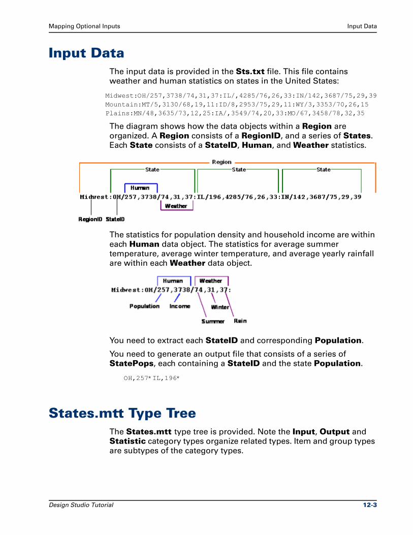
Mapping Optional Inputs Input Data
Input DataThe input data is provided in the Sts.txt file. This file contains
weather and human statistics on states in the United States:
Midwest:OH/257,3738/74,31,37:IL/,4285/76,26,33:IN/142,3687/75,29,39 Mountain:MT/5,3130/68,19,11:ID/8,2953/75,29,11:WY/3,3353/70,26,15 Plains:MN/48,3635/73,12,25:IA/,3549/74,20,33:MO/67,3458/78,32,35
The diagram shows how the data objects within a Region are
organized. A Region consists of a RegionID, and a series of States.
Each State consists of a StateID, Human, and Weather statistics.
The statistics for population density and household income are within
each Human data object. The statistics for average summer
temperature, average winter temperature, and average yearly rainfall
are within each Weather data object.
You need to extract each StateID and corresponding Population.
You need to generate an output file that consists of a series of
StatePops, each containing a StateID and the state Population.
OH,257*IL,196*
States.mtt Type TreeThe States.mtt type tree is provided. Note the Input, Output and
Statistic category types organize related types. Item and group types
are subtypes of the category types.
Design Studio Tutorial 12-3
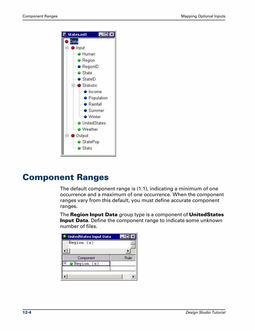
Component Ranges Mapping Optional Inputs
Component RangesThe default component range is (1:1), indicating a minimum of one
occurrence and a maximum of one occurrence. When the component
ranges vary from this default, you must define accurate component
ranges.
The Region Input Data group type is a component of UnitedStates Input Data. Define the component range to indicate some unknown
number of files.
12-4 Design Studio Tutorial
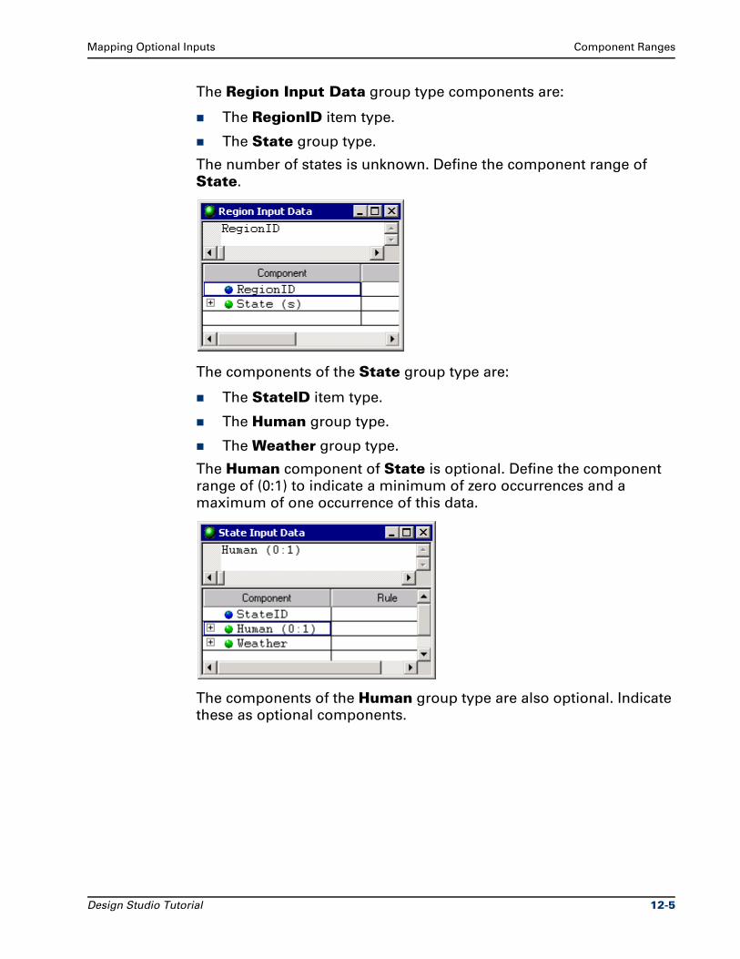
Mapping Optional Inputs Component Ranges
The Region Input Data group type components are:
The RegionID item type.
The State group type.
The number of states is unknown. Define the component range of
State.
The components of the State group type are:
The StateID item type.
The Human group type.
The Weather group type.
The Human component of State is optional. Define the component
range of (0:1) to indicate a minimum of zero occurrences and a
maximum of one occurrence of this data.
The components of the Human group type are also optional. Indicate
these as optional components.
Design Studio Tutorial 12-5
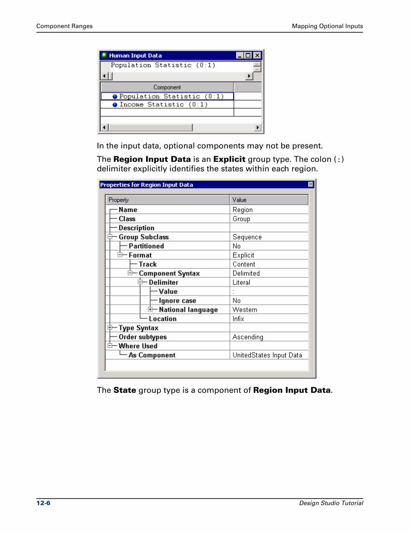
Component Ranges Mapping Optional Inputs
In the input data, optional components may not be present.
The Region Input Data is an Explicit group type. The colon (:)
delimiter explicitly identifies the states within each region.
The State group type is a component of Region Input Data.
12-6 Design Studio Tutorial
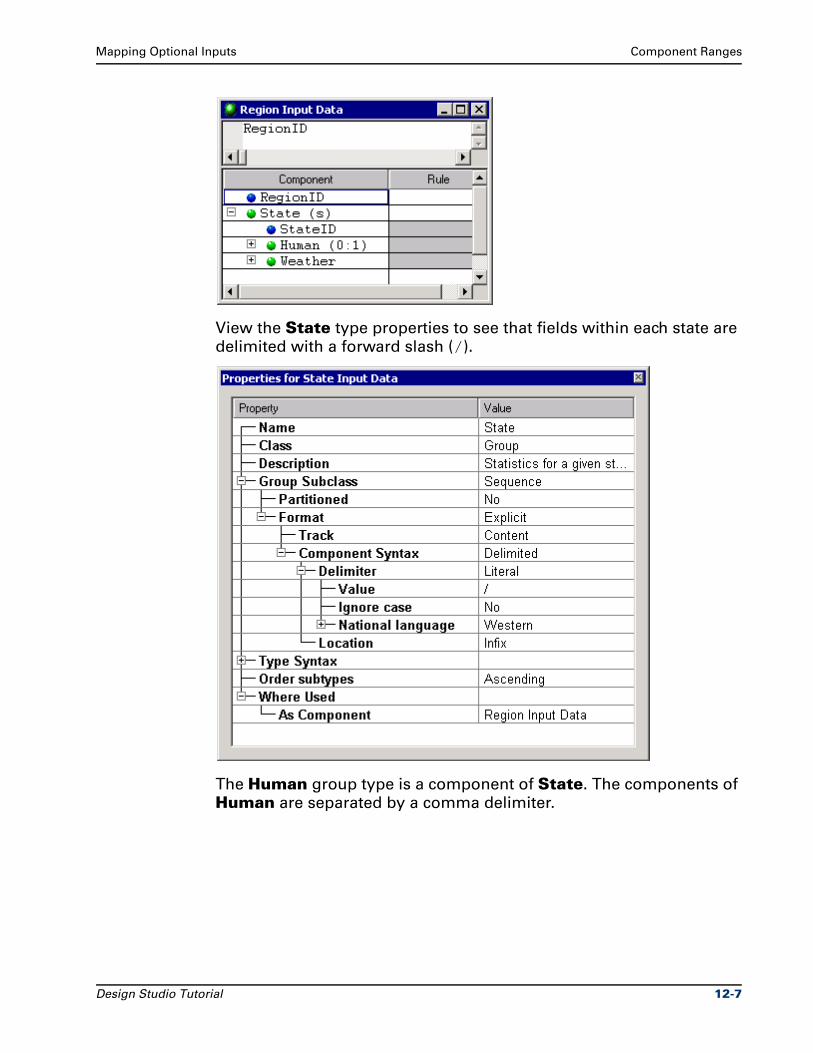
Mapping Optional Inputs Component Ranges
View the State type properties to see that fields within each state are
delimited with a forward slash (/).
The Human group type is a component of State. The components of
Human are separated by a comma delimiter.
Design Studio Tutorial 12-7
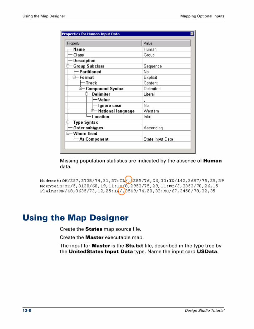
Using the Map Designer Mapping Optional Inputs
Missing population statistics are indicated by the absence of Human
data.
Using the Map DesignerCreate the States map source file.
Create the Master executable map.
The input for Master is the Sts.txt file, described in the type tree by
the UnitedStates Input Data type. Name the input card USData.
12-8 Design Studio Tutorial
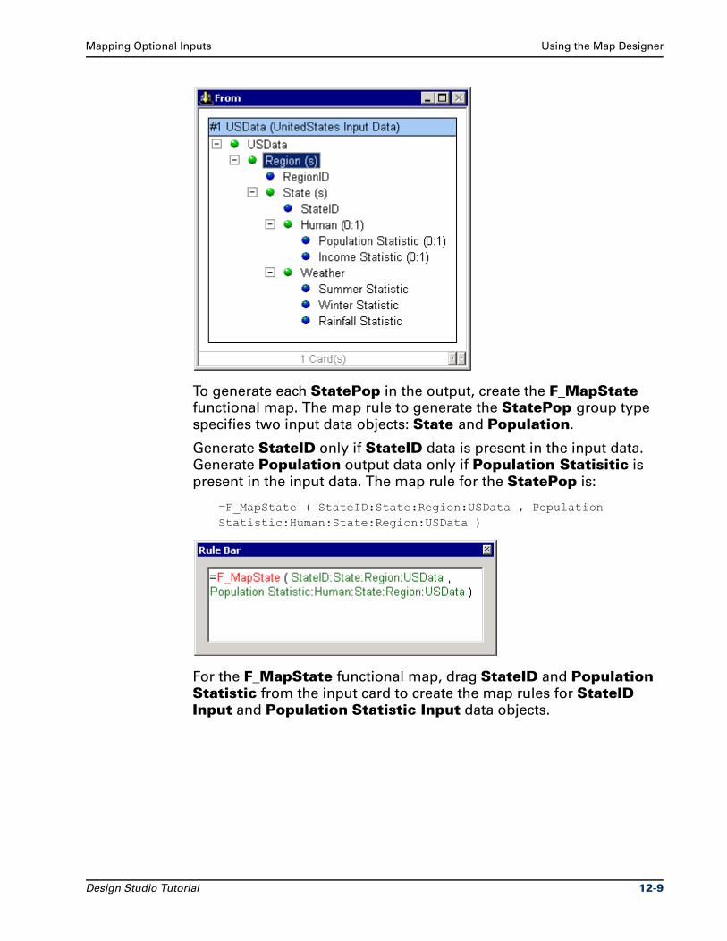
Mapping Optional Inputs Using the Map Designer
To generate each StatePop in the output, create the F_MapState
functional map. The map rule to generate the StatePop group type
specifies two input data objects: State and Population.
Generate StateID only if StateID data is present in the input data.
Generate Population output data only if Population Statisitic is
present in the input data. The map rule for the StatePop is:
=F_MapState ( StateID:State:Region:USData , Population Statistic:Human:State:Region:USData )
For the F_MapState functional map, drag StateID and Population Statistic from the input card to create the map rules for StateID Input and Population Statistic Input data objects.
Design Studio Tutorial 12-9
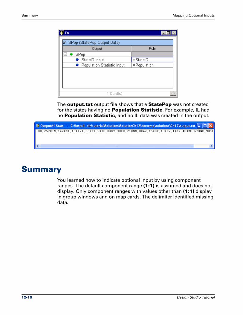
Summary Mapping Optional Inputs
The output.txt output file shows that a StatePop was not created
for the states having no Population Statistic. For example, IL had
no Population Statistic, and no IL data was created in the output.
SummaryYou learned how to indicate optional input by using component
ranges. The default component range (1:1) is assumed and does not
display. Only component ranges with values other than (1:1) display
in group windows and on map cards. The delimiter identified missing
data.
12-10 Design Studio Tutorial
13Mapping Multiple Files to One File
This chapter defines how to map two input files into one output file.
ObjectivesThis chapter uses two input files to create one output file.
By completing the exercises for Chapter 13, you will learn how to:
Map two input files (one header and one detail file) into one output file.
Use ellipses to shorten object names in component rules.
Use nested functional maps.
Files Used in This ChapterYou will be working in the ..\tutorial\my_exercises\ch13 folder.
Files Provided for Chapter 13The following table describes the files provided for this chapter. Use
the files provided in Ch12.exe.
Icon File type Name Description
Text file Header.txt Input data file containing header records
Design Studio Tutorial 13-1
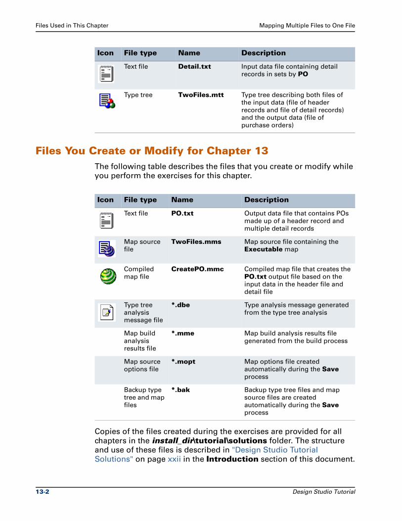
Files Used in This Chapter Mapping Multiple Files to One File
Files You Create or Modify for Chapter 13The following table describes the files that you create or modify while
you perform the exercises for this chapter.
Copies of the files created during the exercises are provided for all
chapters in the install_dir\tutorial\solutions folder. The structure
and use of these files is described in "Design Studio Tutorial
Solutions" on page xxii in the Introduction section of this document.
Text file Detail.txt Input data file containing detail records in sets by PO
Type tree TwoFiles.mtt Type tree describing both files of the input data (file of header records and file of detail records) and the output data (file of purchase orders)
Icon File type Name Description
Icon File type Name Description
Text file PO.txt Output data file that contains POs made up of a header record and multiple detail records
Map source file
TwoFiles.mms Map source file containing the Executable map
Compiled map file
CreatePO.mmc Compiled map file that creates the PO.txt output file based on the input data in the header file and detail file
Type tree analysis message file
*.dbe Type analysis message generated from the type tree analysis
Map build analysis results file
*.mme Map build analysis results file generated from the build process
Map source options file
*.mopt Map options file created automatically during the Save process
Backup type tree and map files
*.bak Backup type tree files and map source files are created automatically during the Save process
13-2 Design Studio Tutorial
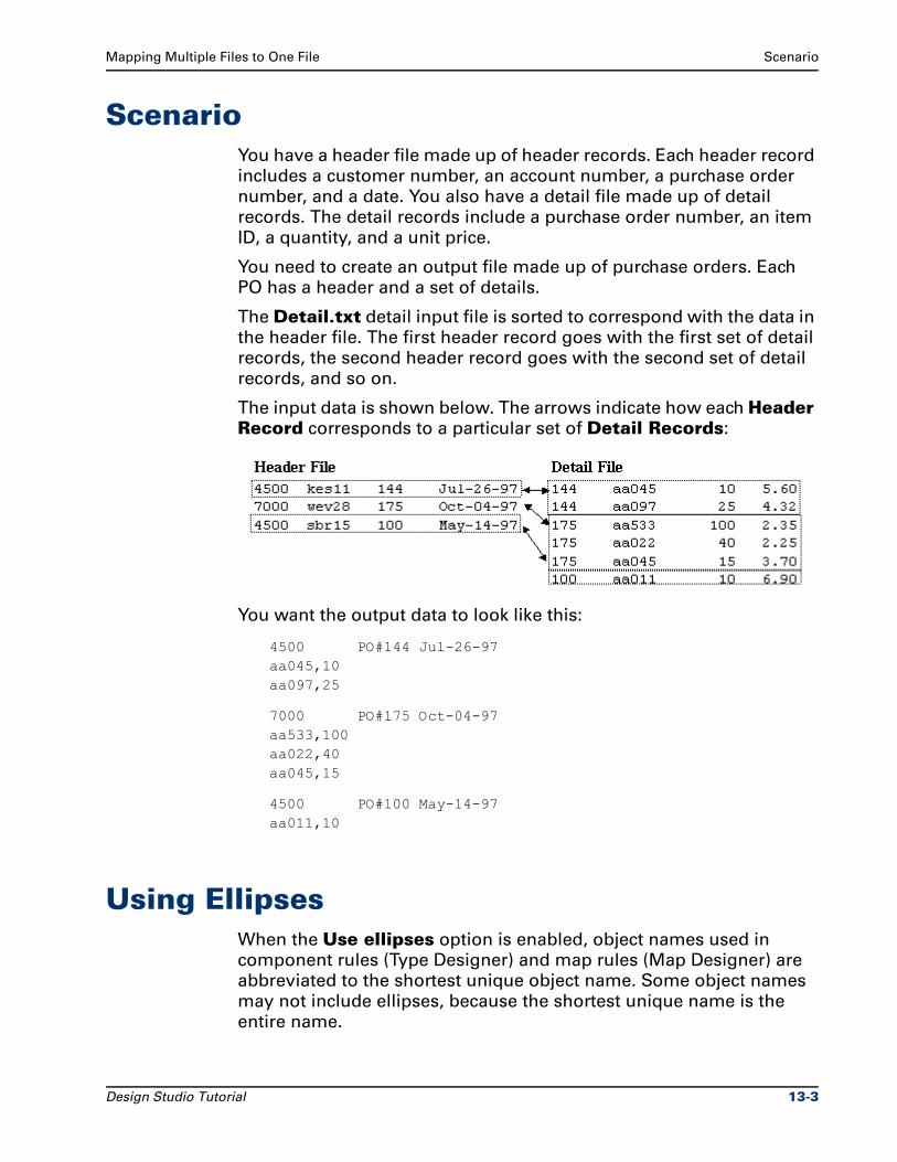
Mapping Multiple Files to One File Scenario
ScenarioYou have a header file made up of header records. Each header record
includes a customer number, an account number, a purchase order
number, and a date. You also have a detail file made up of detail
records. The detail records include a purchase order number, an item
ID, a quantity, and a unit price.
You need to create an output file made up of purchase orders. Each
PO has a header and a set of details.
The Detail.txt detail input file is sorted to correspond with the data in
the header file. The first header record goes with the first set of detail
records, the second header record goes with the second set of detail
records, and so on.
The input data is shown below. The arrows indicate how each Header Record corresponds to a particular set of Detail Records:
You want the output data to look like this:
4500 PO#144 Jul-26-97aa045,10aa097,25
7000 PO#175 Oct-04-97aa533,100aa022,40aa045,15
4500 PO#100 May-14-97aa011,10
Using EllipsesWhen the Use ellipses option is enabled, object names used in
component rules (Type Designer) and map rules (Map Designer) are
abbreviated to the shortest unique object name. Some object names
may not include ellipses, because the shortest unique name is the
entire name.
Design Studio Tutorial 13-3
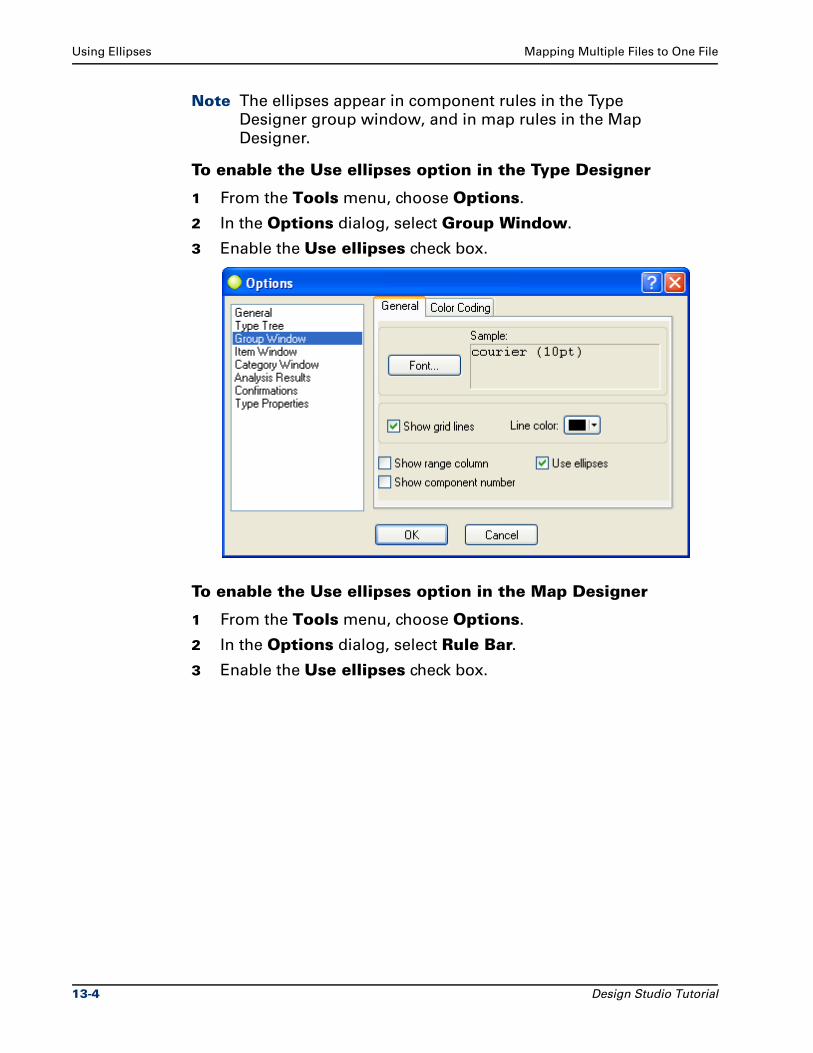
Using Ellipses Mapping Multiple Files to One File
Note The ellipses appear in component rules in the Type
Designer group window, and in map rules in the Map
Designer.
To enable the Use ellipses option in the Type Designer
1 From the Tools menu, choose Options.
2 In the Options dialog, select Group Window.
3 Enable the Use ellipses check box.
To enable the Use ellipses option in the Map Designer
1 From the Tools menu, choose Options.
2 In the Options dialog, select Rule Bar.
3 Enable the Use ellipses check box.
13-4 Design Studio Tutorial
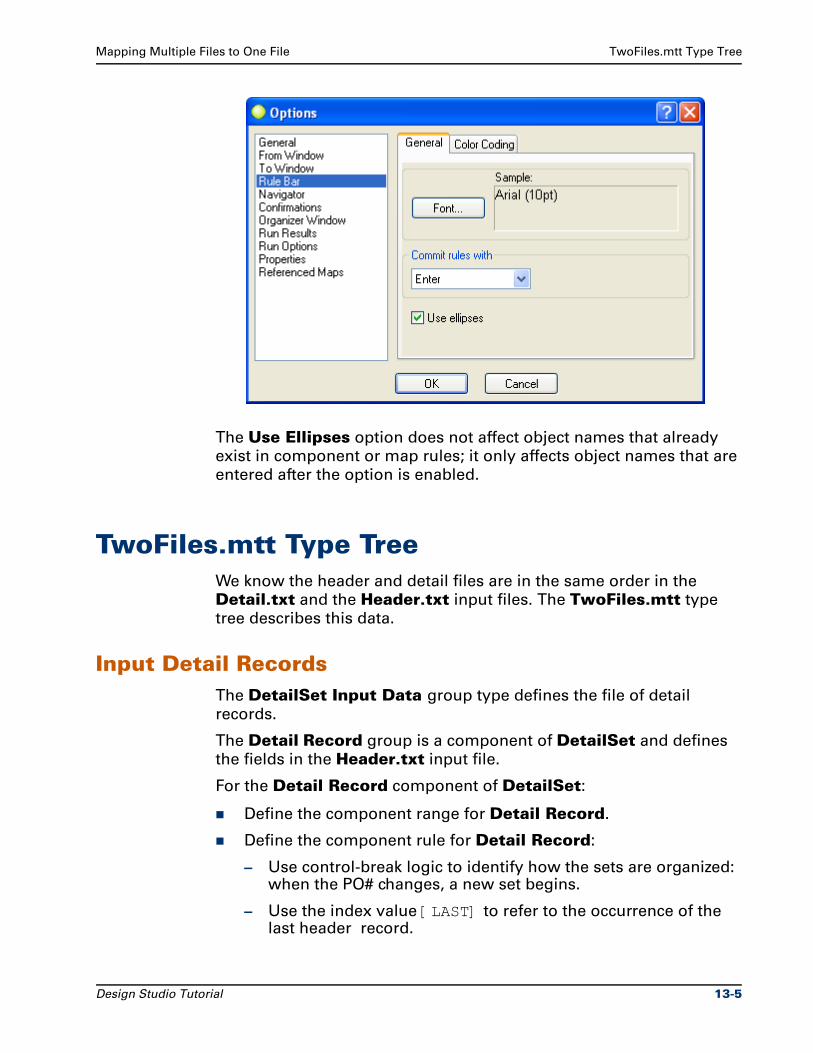
Mapping Multiple Files to One File TwoFiles.mtt Type Tree
The Use Ellipses option does not affect object names that already
exist in component or map rules; it only affects object names that are
entered after the option is enabled.
TwoFiles.mtt Type TreeWe know the header and detail files are in the same order in the
Detail.txt and the Header.txt input files. The TwoFiles.mtt type
tree describes this data.
Input Detail RecordsThe DetailSet Input Data group type defines the file of detail
records.
The Detail Record group is a component of DetailSet and defines
the fields in the Header.txt input file.
For the Detail Record component of DetailSet:
Define the component range for Detail Record.
Define the component rule for Detail Record:
– Use control-break logic to identify how the sets are organized: when the PO# changes, a new set begins.
– Use the index value [LAST] to refer to the occurrence of the last header record.
Design Studio Tutorial 13-5
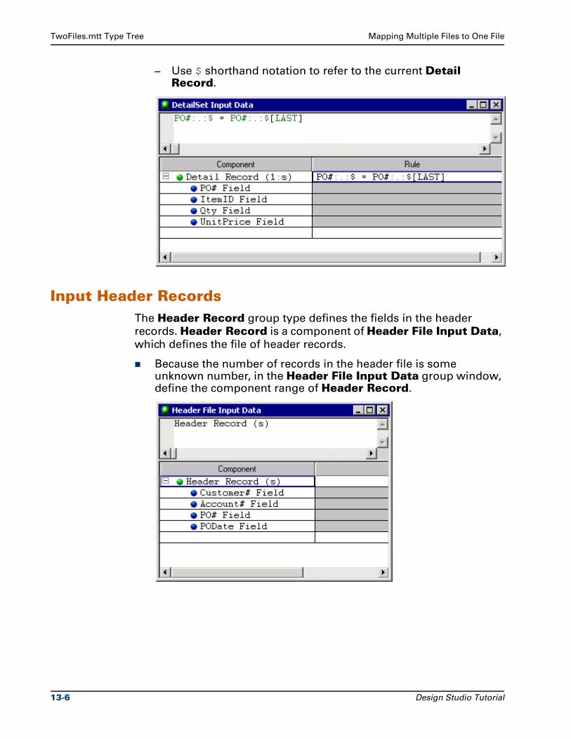
TwoFiles.mtt Type Tree Mapping Multiple Files to One File
– Use $ shorthand notation to refer to the current Detail Record.
Input Header RecordsThe Header Record group type defines the fields in the header
records. Header Record is a component of Header File Input Data,
which defines the file of header records.
Because the number of records in the header file is some unknown number, in the Header File Input Data group window, define the component range of Header Record.
13-6 Design Studio Tutorial
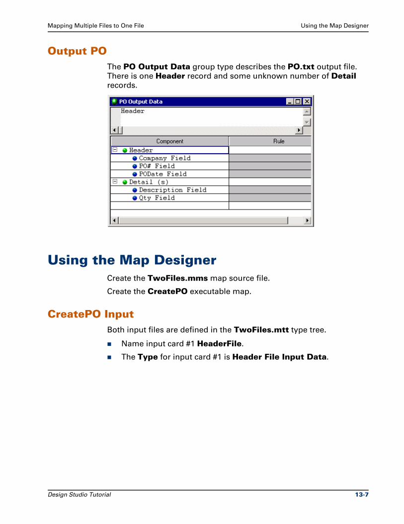
Mapping Multiple Files to One File Using the Map Designer
Output POThe PO Output Data group type describes the PO.txt output file.
There is one Header record and some unknown number of Detail records.
Using the Map DesignerCreate the TwoFiles.mms map source file.
Create the CreatePO executable map.
CreatePO InputBoth input files are defined in the TwoFiles.mtt type tree.
Name input card #1 HeaderFile.
The Type for input card #1 is Header File Input Data.
Design Studio Tutorial 13-7
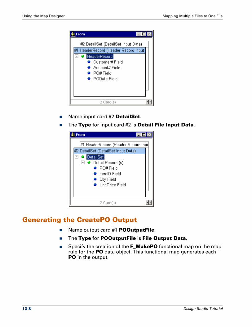
Using the Map Designer Mapping Multiple Files to One File
Name input card #2 DetailSet.
The Type for input card #2 is Detail File Input Data.
Generating the CreatePO OutputName output card #1 POOutputFile.
The Type for POOutputFile is File Output Data.
Specify the creation of the F_MakePO functional map on the map rule for the PO data object. This functional map generates each PO in the output.
13-8 Design Studio Tutorial
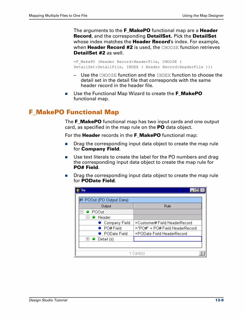
Mapping Multiple Files to One File Using the Map Designer
The arguments to the F_MakePO functional map are a Header Record, and the corresponding DetailSet. Pick the DetailSet
whose index matches the Header Record’s index. For example,
when Header Record #2 is used, the CHOOSE function retrieves
DetailSet #2 as well.
=F_MakePO (Header Record:HeaderFile, CHOOSE ( DetailSet:DetailFile, INDEX ( Header Record:HeaderFile )))
– Use the CHOOSE function and the INDEX function to choose the detail set in the detail file that corresponds with the same header record in the header file.
Use the Functional Map Wizard to create the F_MakePO functional map.
F_MakePO Functional MapThe F_MakePO functional map has two input cards and one output
card, as specified in the map rule on the PO data object.
For the Header records in the F_MakePO functional map:
Drag the corresponding input data object to create the map rule for Company Field.
Use text literals to create the label for the PO numbers and drag the corresponding input data object to create the map rule for PO# Field.
Drag the corresponding input data object to create the map rule for PODate Field.
Design Studio Tutorial 13-9
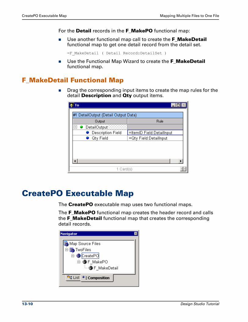
CreatePO Executable Map Mapping Multiple Files to One File
For the Detail records in the F_MakePO functional map:
Use another functional map call to create the F_MakeDetail functional map to get one detail record from the detail set.
=F_MakeDetail ( Detail Record:DetailSet )
Use the Functional Map Wizard to create the F_MakeDetail functional map.
F_MakeDetail Functional MapDrag the corresponding input items to create the map rules for the detail Description and Qty output items.
CreatePO Executable MapThe CreatePO executable map uses two functional maps.
The F_MakePO functional map creates the header record and calls
the F_MakeDetail functional map that creates the corresponding
detail records.
13-10 Design Studio Tutorial
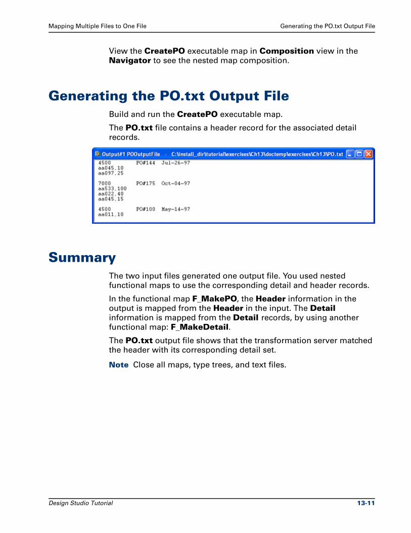
Mapping Multiple Files to One File Generating the PO.txt Output File
View the CreatePO executable map in Composition view in the
Navigator to see the nested map composition.
Generating the PO.txt Output FileBuild and run the CreatePO executable map.
The PO.txt file contains a header record for the associated detail
records.
SummaryThe two input files generated one output file. You used nested
functional maps to use the corresponding detail and header records.
In the functional map F_MakePO, the Header information in the
output is mapped from the Header in the input. The Detail information is mapped from the Detail records, by using another
functional map: F_MakeDetail.
The PO.txt output file shows that the transformation server matched
the header with its corresponding detail set.
Note Close all maps, type trees, and text files.
Design Studio Tutorial 13-11

Summary Mapping Multiple Files to One File
13-12 Design Studio Tutorial

14Detail Records Not Sorted by PO
In Chapter 13, the detail records in the Detail.txt file were in the same
order as the corresponding header records in the Header.txt file.
Your data may be in random order and not be sorted or organized into
sets.
ObjectivesThis exercise associates randomly ordered detail records with the
correct header record.
By completing the exercises for Chapter 14, you will learn how to:
Associate randomly sorted detail records with header records.
Use the EXTRACT function to extract a detail record from the detail file when the PO# of the detail record is equal to the PO# of the header record.
Close all run results windows at the same time.
Files Used in This ChapterYou will be working in the ..\tutorial\my_exercises\ch14 folder.
Files Provided for Chapter 14The following table describes the files provided for this chapter. Use
the files provided in Ch14.exe.
Design Studio Tutorial 14-1
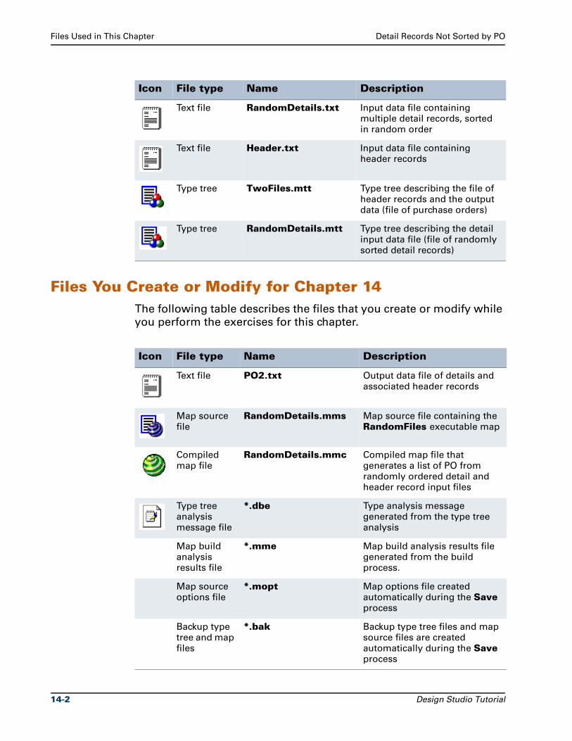
Files Used in This Chapter Detail Records Not Sorted by PO
Files You Create or Modify for Chapter 14The following table describes the files that you create or modify while
you perform the exercises for this chapter.
Icon File type Name Description
Text file RandomDetails.txt Input data file containing multiple detail records, sorted in random order
Text file Header.txt Input data file containing header records
Type tree TwoFiles.mtt Type tree describing the file of header records and the output data (file of purchase orders)
Type tree RandomDetails.mtt Type tree describing the detail input data file (file of randomly sorted detail records)
Icon File type Name Description
Text file PO2.txt Output data file of details and associated header records
Map source file
RandomDetails.mms Map source file containing the RandomFiles executable map
Compiled map file
RandomDetails.mmc Compiled map file that generates a list of PO from randomly ordered detail and header record input files
Type tree analysis message file
*.dbe Type analysis message generated from the type tree analysis
Map build analysis results file
*.mme Map build analysis results file generated from the build process.
Map source options file
*.mopt Map options file created automatically during the Save process
Backup type tree and map files
*.bak Backup type tree files and map source files are created automatically during the Save process
14-2 Design Studio Tutorial
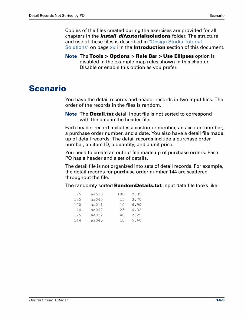
Detail Records Not Sorted by PO Scenario
Copies of the files created during the exercises are provided for all
chapters in the install_dir\tutorial\solutions folder. The structure
and use of these files is described in "Design Studio Tutorial
Solutions" on page xxii in the Introduction section of this document.
Note The Tools > Options > Rule Bar > Use Ellipses option is
disabled in the example map rules shown in this chapter.
Disable or enable this option as you prefer.
ScenarioYou have the detail records and header records in two input files. The
order of the records in the files is random.
Note The Detail.txt detail input file is not sorted to correspond
with the data in the header file.
Each header record includes a customer number, an account number,
a purchase order number, and a date. You also have a detail file made
up of detail records. The detail records include a purchase order
number, an item ID, a quantity, and a unit price.
You need to create an output file made up of purchase orders. Each
PO has a header and a set of details.
The detail file is not organized into sets of detail records. For example,
the detail records for purchase order number 144 are scattered
throughout the file.
The randomly sorted RandomDetails.txt input data file looks like:
175 aa533 100 2.35175 aa045 15 3.70100 aa011 10 6.90144 aa097 25 4.32175 aa022 40 2.25144 aa045 10 5.60
Design Studio Tutorial 14-3
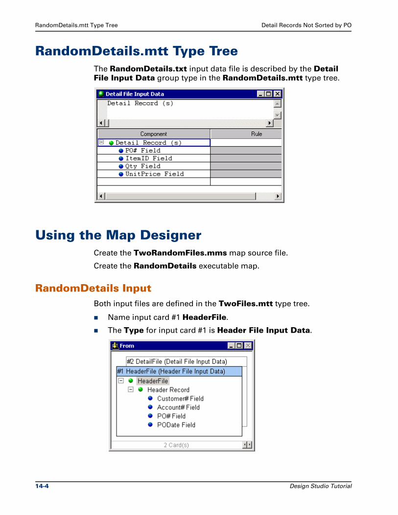
RandomDetails.mtt Type Tree Detail Records Not Sorted by PO
RandomDetails.mtt Type TreeThe RandomDetails.txt input data file is described by the Detail File Input Data group type in the RandomDetails.mtt type tree.
Using the Map DesignerCreate the TwoRandomFiles.mms map source file.
Create the RandomDetails executable map.
RandomDetails InputBoth input files are defined in the TwoFiles.mtt type tree.
Name input card #1 HeaderFile.
The Type for input card #1 is Header File Input Data.
14-4 Design Studio Tutorial
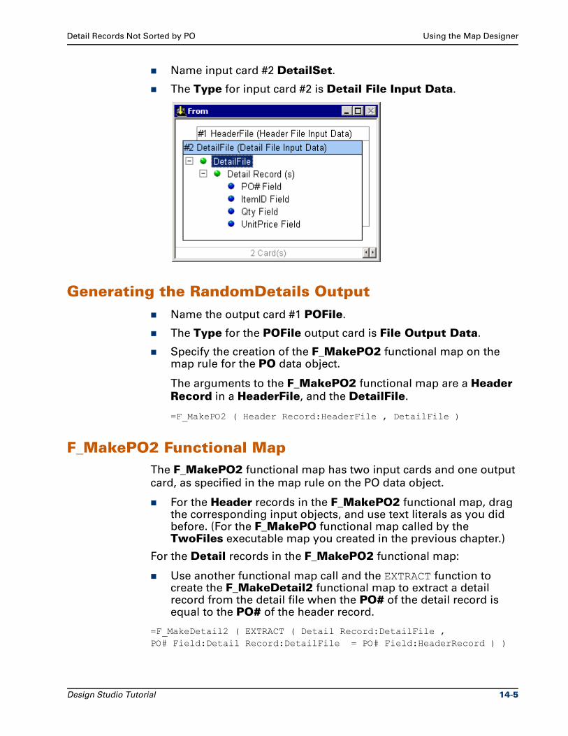
Detail Records Not Sorted by PO Using the Map Designer
Name input card #2 DetailSet.
The Type for input card #2 is Detail File Input Data.
Generating the RandomDetails OutputName the output card #1 POFile.
The Type for the POFile output card is File Output Data.
Specify the creation of the F_MakePO2 functional map on the map rule for the PO data object.
The arguments to the F_MakePO2 functional map are a Header Record in a HeaderFile, and the DetailFile.
=F_MakePO2 ( Header Record:HeaderFile , DetailFile )
F_MakePO2 Functional MapThe F_MakePO2 functional map has two input cards and one output
card, as specified in the map rule on the PO data object.
For the Header records in the F_MakePO2 functional map, drag the corresponding input objects, and use text literals as you did before. (For the F_MakePO functional map called by the TwoFiles executable map you created in the previous chapter.)
For the Detail records in the F_MakePO2 functional map:
Use another functional map call and the EXTRACT function to create the F_MakeDetail2 functional map to extract a detail record from the detail file when the PO# of the detail record is equal to the PO# of the header record.
=F_MakeDetail2 ( EXTRACT ( Detail Record:DetailFile , PO# Field:Detail Record:DetailFile = PO# Field:HeaderRecord ) )
Design Studio Tutorial 14-5
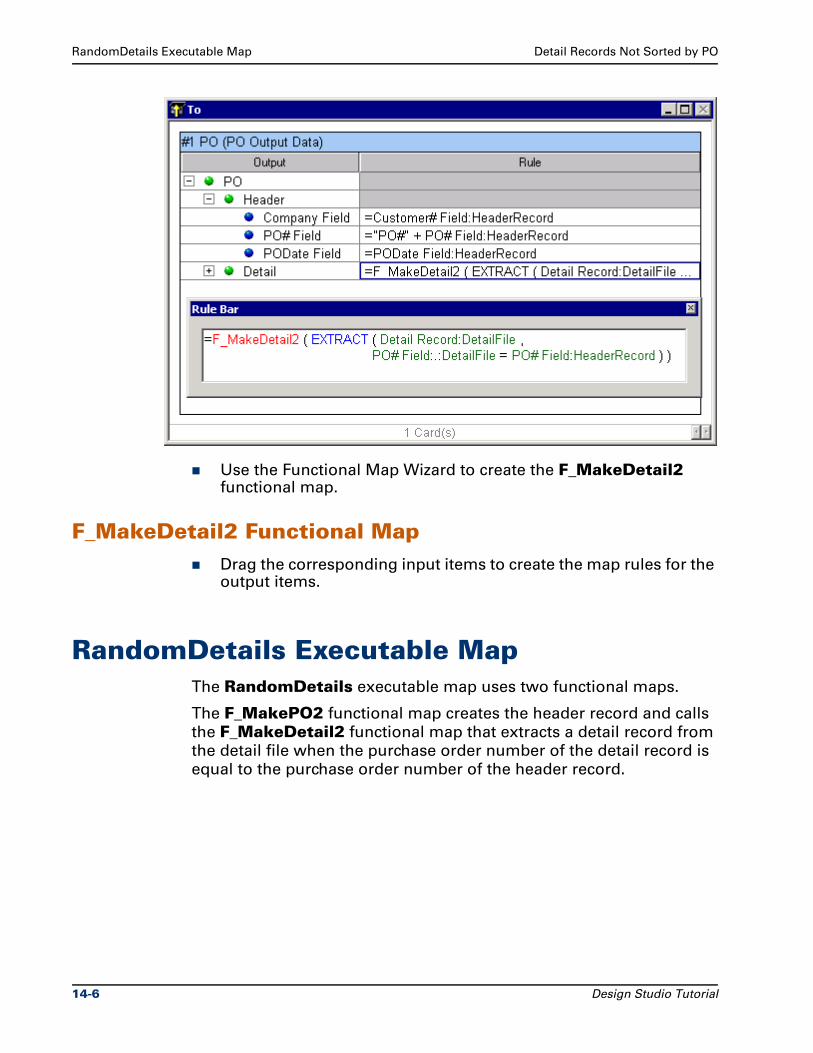
RandomDetails Executable Map Detail Records Not Sorted by PO
Use the Functional Map Wizard to create the F_MakeDetail2 functional map.
F_MakeDetail2 Functional MapDrag the corresponding input items to create the map rules for the output items.
RandomDetails Executable MapThe RandomDetails executable map uses two functional maps.
The F_MakePO2 functional map creates the header record and calls
the F_MakeDetail2 functional map that extracts a detail record from
the detail file when the purchase order number of the detail record is
equal to the purchase order number of the header record.
14-6 Design Studio Tutorial
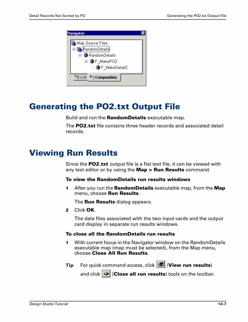
Detail Records Not Sorted by PO Generating the PO2.txt Output File
Generating the PO2.txt Output FileBuild and run the RandomDetails executable map.
The PO2.txt file contains three header records and associated detail
records.
Viewing Run ResultsSince the PO2.txt output file is a flat text file, it can be viewed with
any text editor or by using the Map > Run Results command.
To view the RandomDetails run results windows
1 After you run the RandomDetails executable map, from the Map menu, choose Run Results.
The Run Results dialog appears.
2 Click OK.
The data files associated with the two input cards and the output
card display in separate run results windows.
To close all the RandomDetails run results
1 With current focus in the Navigator window on the RandomDetails executable map (map must be selected), from the Map menu, choose Close All Run Results.
Tip For quick command access, click (View run results)
and click (Close all run results) tools on the toolbar.
Design Studio Tutorial 14-7
Summary Detail Records Not Sorted by PO
The position of the windows associated with map source files is
stored in a mmsname.mopt file. The RandomDetails.mopt file
stores the position and run results window information.
SummaryRandomly ordered detail records were associated with header records
by identifying matching purchase order numbers. The F_MakePO2
functional map processed the header records in the header file and
the detail file.
On the output card of the F_MakePO2 functional map, the map rule
for the Detail called the F_MakeDetail2 functional map.
This nested functional map used the EXTRACT function to extract
records where the purchase order number in the detail file equaled
the purchase order number in the header record.
Note Close all maps, type trees, and text files.
14-8 Design Studio Tutorial
15Creating a Trace File
The trace file is a text file that records the progress during the
execution of a map. You can choose to trace the input data, the output
data or both. The trace file is a debugging aid used to diagnose invalid
data or incorrect type definitions.
ObjectivesThis exercise creates a trace file that can be used for debugging
purposes.
By completing the exercises for Chapter 15, you will learn how to:
Create a trace file.
View the trace file on the Trace tab on the Organizer window.
View the trace file in a separate window.
Understand the contents of a trace file.
Change the trace file settings.
Files Used in This ChapterYou will be working in the ..\tutorial\my_exercises\ch15 folder.
Design Studio Tutorial 15-1
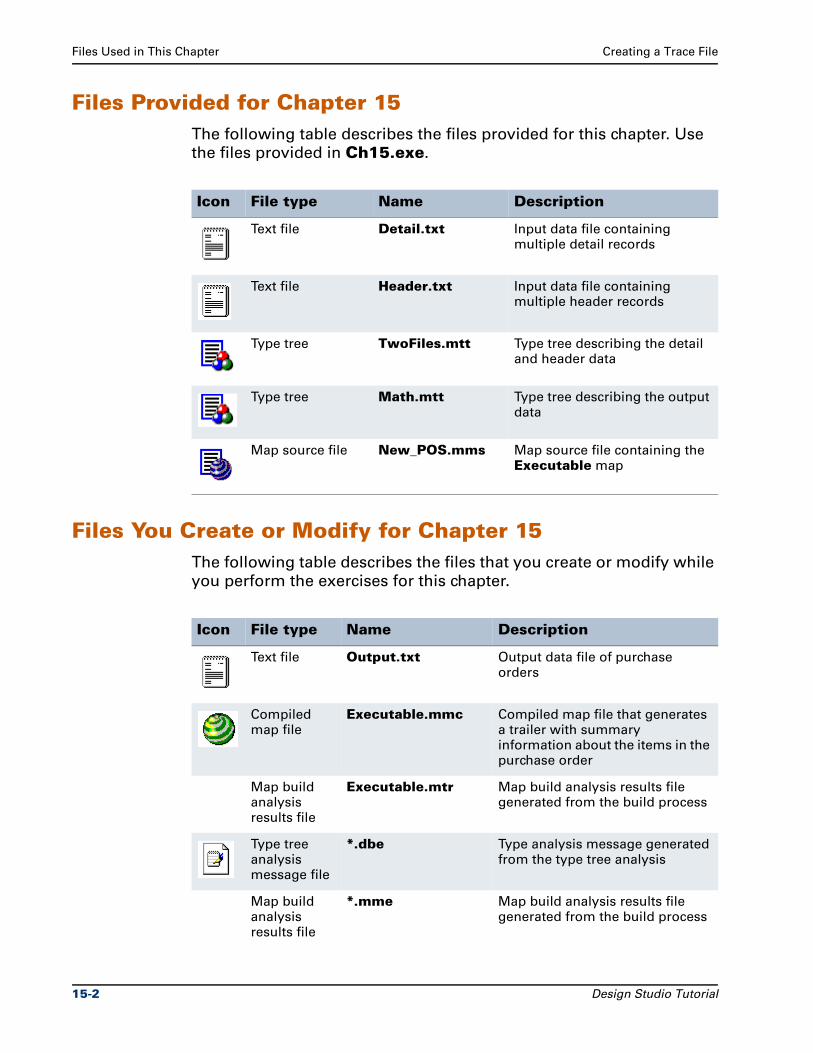
Files Used in This Chapter Creating a Trace File
Files Provided for Chapter 15The following table describes the files provided for this chapter. Use
the files provided in Ch15.exe.
Files You Create or Modify for Chapter 15The following table describes the files that you create or modify while
you perform the exercises for this chapter.
Icon File type Name Description
Text file Detail.txt Input data file containing multiple detail records
Text file Header.txt Input data file containing multiple header records
Type tree TwoFiles.mtt Type tree describing the detail and header data
Type tree Math.mtt Type tree describing the output data
Map source file New_POS.mms Map source file containing the Executable map
Icon File type Name Description
Text file Output.txt Output data file of purchase orders
Compiled map file
Executable.mmc Compiled map file that generates a trailer with summary information about the items in the purchase order
Map build analysis results file
Executable.mtr Map build analysis results file generated from the build process
Type tree analysis message file
*.dbe Type analysis message generated from the type tree analysis
Map build analysis results file
*.mme Map build analysis results file generated from the build process
15-2 Design Studio Tutorial
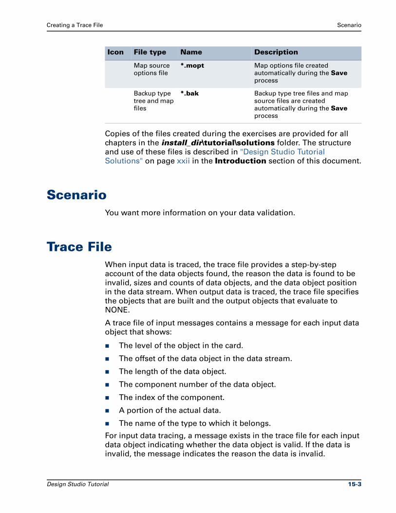
Creating a Trace File Scenario
Copies of the files created during the exercises are provided for all
chapters in the install_dir\tutorial\solutions folder. The structure
and use of these files is described in "Design Studio Tutorial
Solutions" on page xxii in the Introduction section of this document.
ScenarioYou want more information on your data validation.
Trace FileWhen input data is traced, the trace file provides a step-by-step
account of the data objects found, the reason the data is found to be
invalid, sizes and counts of data objects, and the data object position
in the data stream. When output data is traced, the trace file specifies
the objects that are built and the output objects that evaluate to
NONE.
A trace file of input messages contains a message for each input data
object that shows:
The level of the object in the card.
The offset of the data object in the data stream.
The length of the data object.
The component number of the data object.
The index of the component.
A portion of the actual data.
The name of the type to which it belongs.
For input data tracing, a message exists in the trace file for each input
data object indicating whether the data object is valid. If the data is
invalid, the message indicates the reason the data is invalid.
Map source options file
*.mopt Map options file created automatically during the Save process
Backup type tree and map files
*.bak Backup type tree files and map source files are created automatically during the Save process
Icon File type Name Description
Design Studio Tutorial 15-3
Trace File Creating a Trace File
The trace file is created as specified after the map is compiled and
executed.
The default name of the trace file is the executable map name, plus
the file name extension .mtr. The default location of the trace file is
the map execution directory. A specific name and location of the trace
file can be defined in the Map Settings dialog.
For example, if your executable map name is RegionReport, the
trace file is RegionReport.mtr.
After you run a map, the trace file can be viewed on the Trace tab in
the organizer window or with any text editor.
Creating a Trace FileTurn on the trace file only for debugging purposes. The trace file can
slow down execution.
To create a trace file for the Executable map
1 Open the New_POS map source file.
2 Select the Executable map in the Navigator.
3 From the Map menu, choose Settings.
4 Right-click MapTrace and choose Expand All to view the map trace settings.
5 For the ContentTrace > Switch setting, choose ON.
6 Click OK.
7 Build and run the Executable map.
The trace file is created.
If you ran a map and got a message that an input was invalid, turn on
the input trace only. If you got a message that an output was invalid,
turn on the output trace only.
Changing MapTrace SettingsUse the MapTrace settings in the Map Settings dialog to change the
location, name, and contents of the trace file.
Note Read the Help for any field to determine the value and
options for that setting.
15-4 Design Studio Tutorial
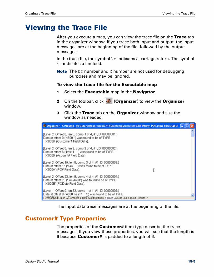
Creating a Trace File Viewing the Trace File
Viewing the Trace FileAfter you execute a map, you can view the trace file on the Trace tab
in the organizer window. If you trace both input and output, the input
messages are at the beginning of the file, followed by the output
messages.
In the trace file, the symbol \r indicates a carriage return. The symbol
\n indicates a linefeed.
Note The DI number and X number are not used for debugging
purposes and may be ignored.
To view the trace file for the Executable map
1 Select the Executable map in the Navigator.
2 On the toolbar, click (Organizer) to view the Organizer
window.
3 Click the Trace tab on the Organizer window and size the window as needed.
The input data trace messages are at the beginning of the file.
Customer# Type PropertiesThe properties of the Customer# item type describe the trace
messages. If you view these properties, you will see that the length is
6 because Customer# is padded to a length of 6.
Design Studio Tutorial 15-5
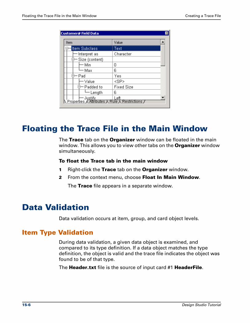
Floating the Trace File in the Main Window Creating a Trace File
Floating the Trace File in the Main WindowThe Trace tab on the Organizer window can be floated in the main
window. This allows you to view other tabs on the Organizer window
simultaneously.
To float the Trace tab in the main window
1 Right-click the Trace tab on the Organizer window.
2 From the context menu, choose Float In Main Window.
The Trace file appears in a separate window.
Data ValidationData validation occurs at item, group, and card object levels.
Item Type ValidationDuring data validation, a given data object is examined, and
compared to its type definition. If a data object matches the type
definition, the object is valid and the trace file indicates the object was
found to be of that type.
The Header.txt file is the source of input card #1 HeaderFile.
15-6 Design Studio Tutorial
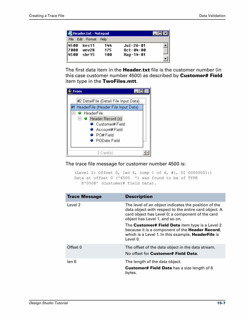
Creating a Trace File Data Validation
The first data item in the Header.txt file is the customer number (in
this case customer number 4500) as described by Customer# Field
item type in the TwoFiles.mtt.
The trace file message for customer number 4500 is:
(Level 2: Offset 0, len 6, comp 1 of 4, #1, DI 00000001:)Data at offset 0 ('4500 ') was found to be of TYPE X'0008' (Customer# Field Data).
Trace Message Description
Level 2 The level of an object indicates the position of the data object with respect to the entire card object. A card object has Level 0; a component of the card object has Level 1, and so on.
The Customer# Field Data item type is a Level 2 because it is a component of the Header Record, which is a Level 1. In this example, HeaderFile is Level 0.
Offset 0 The offset of the data object in the data stream.
No offset for Customer# Field Data.
len 6 The length of the data object.
Customer# Field Data has a size length of 6 bytes.
Design Studio Tutorial 15-7
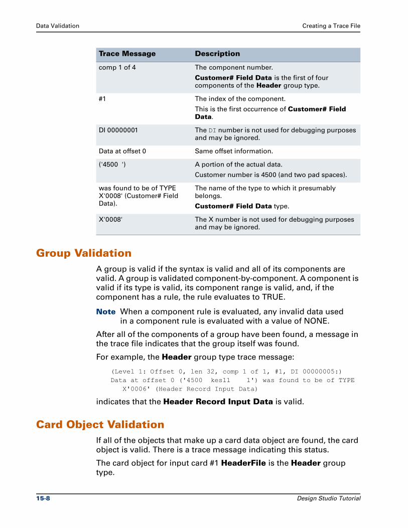
Data Validation Creating a Trace File
Group ValidationA group is valid if the syntax is valid and all of its components are
valid. A group is validated component-by-component. A component is
valid if its type is valid, its component range is valid, and, if the
component has a rule, the rule evaluates to TRUE.
Note When a component rule is evaluated, any invalid data used
in a component rule is evaluated with a value of NONE.
After all of the components of a group have been found, a message in
the trace file indicates that the group itself was found.
For example, the Header group type trace message:
(Level 1: Offset 0, len 32, comp 1 of 1, #1, DI 00000005:)Data at offset 0 ('4500 kes11 1') was found to be of TYPE X'0006' (Header Record Input Data)
indicates that the Header Record Input Data is valid.
Card Object ValidationIf all of the objects that make up a card data object are found, the card
object is valid. There is a trace message indicating this status.
The card object for input card #1 HeaderFile is the Header group
type.
comp 1 of 4 The component number.
Customer# Field Data is the first of four components of the Header group type.
#1 The index of the component.
This is the first occurrence of Customer# Field Data.
DI 00000001 The DI number is not used for debugging purposes and may be ignored.
Data at offset 0 Same offset information.
('4500 ') A portion of the actual data.
Customer number is 4500 (and two pad spaces).
was found to be of TYPE X'0008' (Customer# Field Data).
The name of the type to which it presumably belongs.
Customer# Field Data type.
X'0008' The X number is not used for debugging purposes and may be ignored.
Trace Message Description
15-8 Design Studio Tutorial
Creating a Trace File Invalid Data
The trace message for Header File Input Data (the Type defined for
input card #1) is:
(Level 0: Offset 0, len 102, comp 1 of 0, #1, DI 00000010:)Data at offset 0 ('4500 kes11 1') was found to be of TYPE X'0004' (Header File Input Data).
The message following this card object appears after all of the
messages for the objects within that card:
INPUT 1 was valid.
End of Validation messages for INPUT CARD 1.
Final Trace MessageThis message appears at the end of the trace file.
End of Execution messages.
Invalid DataWhen a data object does not match the definition of the type to which
it presumably belongs, it could be invalid.
Following are possible reasons for an invalid data object:
Item value is not in restriction list
Item failed the presentation test
Item is the wrong size
Data object has the wrong delimiter
Data object has the wrong terminator
Data object failed the component rule
Group is missing a required component
Group contains one or more invalid component(s)
See the Map Designer Reference Guide for details on invalid data.
SummaryTrace files should be used only for debugging purposes because the
trace process impacts performance. Information in trace files can help
you debug input data, output data, and type property definitions.
Design Studio Tutorial 15-9

Summary Creating a Trace File
Note Close all maps, type trees, and text files.
15-10 Design Studio Tutorial
16Exporting a Map
Exporting a map source file enables you to store map definitions in
xml format in a repository directory. The resulting xml file contains
information on map settings, card settings, and map rules.
ObjectivesThis chapter exports the New_POS map source file.
By completing the exercises for Chapter 16, you will learn how to:
Export a map source file.
Files Used in This ChapterYou will be working in the ..\tutorial\my_exercises\ch16 folder.
Files Provided for Chapter 16The following table describes the files provided for this chapter. Use
the files provided in Ch16.exe.
Icon File type Name Description
Text file Detail.txt Input data file containing multiple detail records
Design Studio Tutorial 16-1
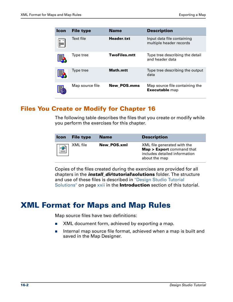
XML Format for Maps and Map Rules Exporting a Map
Files You Create or Modify for Chapter 16The following table describes the files that you create or modify while
you perform the exercises for this chapter.
Copies of the files created during the exercises are provided for all
chapters in the install_dir\tutorial\solutions folder. The structure
and use of these files is described in "Design Studio Tutorial
Solutions" on page xxii in the Introduction section of this tutorial.
XML Format for Maps and Map RulesMap source files have two definitions:
XML document form, achieved by exporting a map.
Internal map source file format, achieved when a map is built and saved in the Map Designer.
Text file Header.txt Input data file containing multiple header records
Type tree TwoFiles.mtt Type tree describing the detail and header data
Type tree Math.mtt Type tree describing the output data
Map source file New_POS.mms Map source file containing the Executable map
Icon File type Name Description
Icon File type Name Description
XML file New_POS.xml XML file generated with the Map > Export command that includes detailed information about the map
16-2 Design Studio Tutorial
Exporting a Map Exporting the New_PO
Exporting the New_POThe Map > Export command converts a map source file definition
from the internal map format to the xml document form.
To export the New_POS map
1 Open the New_POS map source file.
2 In the Navigator, select the Executable map.
The active map name displays on the title bar.
3 From the Map menu, choose Export.
The Export Map(s) to an XML file dialog appears with the
active map name in the File name field.
4 To export to the current folder, click Select.
The Maps exported successfully confirmation message
appears.
5 Click OK.
The resulting New_POS.xml file can be opened with a text editor.
Note To view the exported xml file in a browser, you must use the
mapsettings.dtd and the mms.dtd files provided in the
install_dir\mapimportexport\dtd folder.
XML DTDThe mapsettings.dtd and the mms.dtd files are required to view
the exported xml file in a browser. These *.dtd files are provided in
the install_dir\mapimportexport\dtd folder.
Export maps to this install_dir\mapimportexport\dtd location or
copy these dtd files to the export map location.
To export the New_POS map to be opened in a browser
1 Open the New_POS map source file.
2 In the Navigator, select the Executable map.
The active map name displays on the title bar.
3 From the Map menu, choose Export.
The Export Map(s) to an XML file dialog appears with the
active map name in the File name field.
4 For the Save in field, navigate your file system to specify the Design Studio install_dir\mapimportexport\dtd folder.
Design Studio Tutorial 16-3
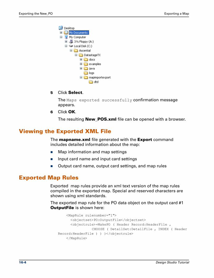
Exporting the New_PO Exporting a Map
5 Click Select.
The Maps exported successfully confirmation message
appears.
6 Click OK.
The resulting New_POS.xml file can be opened with a browser.
Viewing the Exported XML FileThe mapname.xml file generated with the Export command
includes detailed information about the map:
Map information and map settings
Input card name and input card settings
Output card name, output card settings, and map rules
Exported Map RulesExported map rules provide an xml text version of the map rules
compiled in the exported map. Special and reserved characters are
shown using xml standards.
The exported map rule for the PO data object on the output card #1
OutputFile is shown here:
<MapRule rulenumber="1"> <objectset>PO:OutputFile</objectset> <objectrule>=MakePO ( Header Record:HeaderFile , CHOOSE ( DetailSet:DetailFile , INDEX ( Header Record:HeaderFile ) ) )</objectrule> </MapRule>
16-4 Design Studio Tutorial
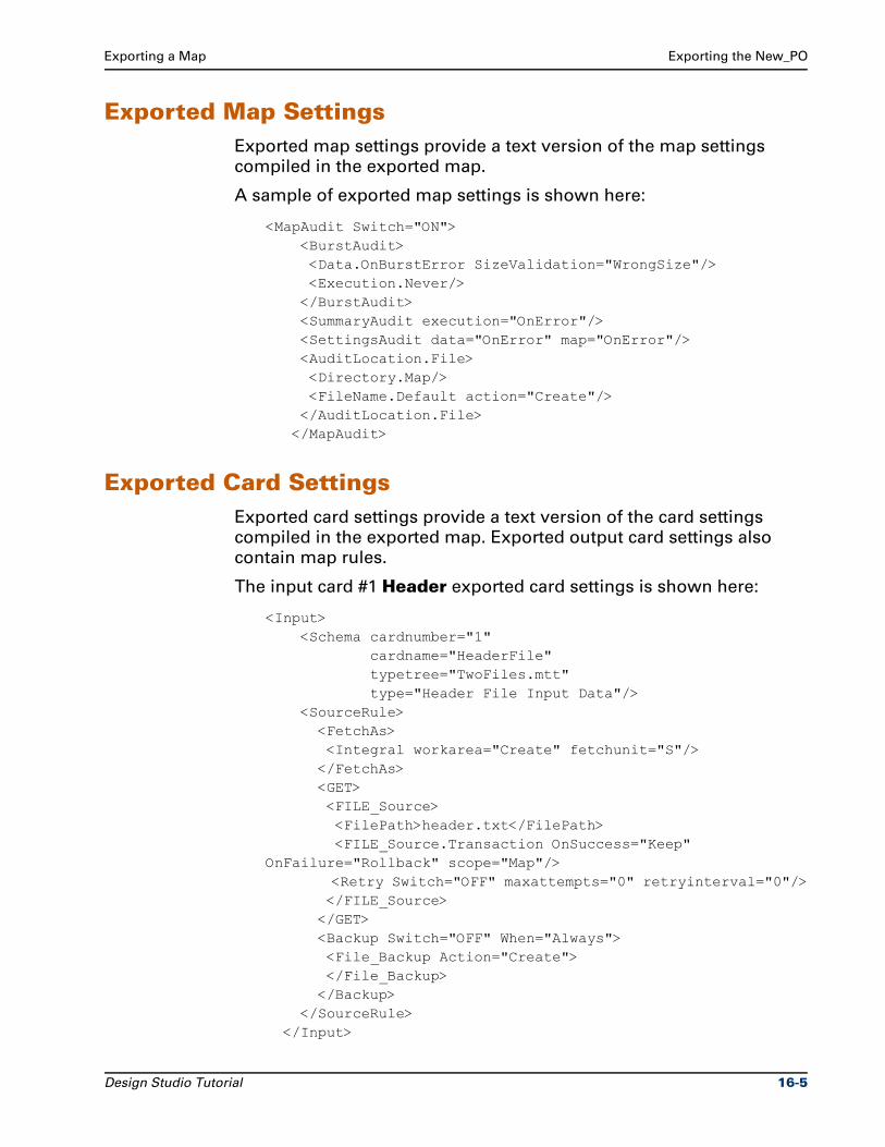
Exporting a Map Exporting the New_PO
Exported Map SettingsExported map settings provide a text version of the map settings
compiled in the exported map.
A sample of exported map settings is shown here:
<MapAudit Switch="ON"> <BurstAudit> <Data.OnBurstError SizeValidation="WrongSize"/> <Execution.Never/> </BurstAudit> <SummaryAudit execution="OnError"/> <SettingsAudit data="OnError" map="OnError"/> <AuditLocation.File> <Directory.Map/> <FileName.Default action="Create"/> </AuditLocation.File> </MapAudit>
Exported Card SettingsExported card settings provide a text version of the card settings
compiled in the exported map. Exported output card settings also
contain map rules.
The input card #1 Header exported card settings is shown here:
<Input> <Schema cardnumber="1" cardname="HeaderFile" typetree="TwoFiles.mtt" type="Header File Input Data"/> <SourceRule> <FetchAs> <Integral workarea="Create" fetchunit="S"/> </FetchAs> <GET> <FILE_Source> <FilePath>header.txt</FilePath> <FILE_Source.Transaction OnSuccess="Keep" OnFailure="Rollback" scope="Map"/> <Retry Switch="OFF" maxattempts="0" retryinterval="0"/> </FILE_Source> </GET> <Backup Switch="OFF" When="Always"> <File_Backup Action="Create"> </File_Backup> </Backup> </SourceRule> </Input>
Design Studio Tutorial 16-5
Summary Exporting a Map
SummaryThe exported xml open document interface is useful for:
Storing and retrieving map definitions in a repository.
Printing map definitions.
Global impact analysis.
Converting business rules from other sources to map rules.
Documentation.
Exported maps also provide an alternate format for storing map
definitions in XML format in version control systems. The
mapsettings.dtd and the mms.dtd files are required to view the
exported XML file in a browser.
Note Close all maps, type trees, and text files.
16-6 Design Studio Tutorial
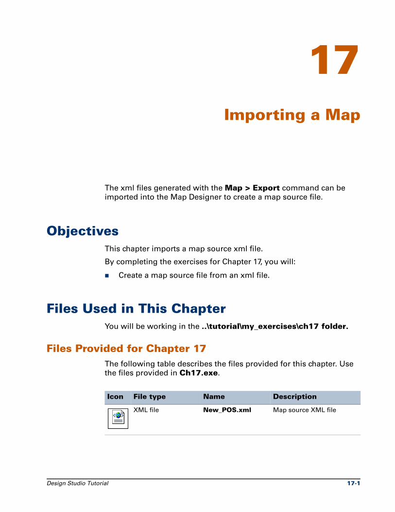
17Importing a Map
The xml files generated with the Map > Export command can be
imported into the Map Designer to create a map source file.
ObjectivesThis chapter imports a map source xml file.
By completing the exercises for Chapter 17, you will:
Create a map source file from an xml file.
Files Used in This ChapterYou will be working in the ..\tutorial\my_exercises\ch17 folder.
Files Provided for Chapter 17The following table describes the files provided for this chapter. Use
the files provided in Ch17.exe.
Icon File type Name Description
XML file New_POS.xml Map source XML file
Design Studio Tutorial 17-1
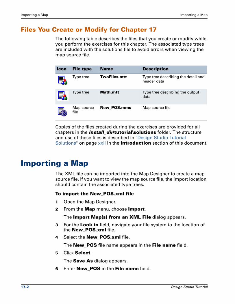
Importing a Map Importing a Map
Files You Create or Modify for Chapter 17The following table describes the files that you create or modify while
you perform the exercises for this chapter. The associated type trees
are included with the solutions file to avoid errors when viewing the
map source file.
Copies of the files created during the exercises are provided for all
chapters in the install_dir\tutorial\solutions folder. The structure
and use of these files is described in "Design Studio Tutorial
Solutions" on page xxii in the Introduction section of this document.
Importing a MapThe XML file can be imported into the Map Designer to create a map
source file. If you want to view the map source file, the import location
should contain the associated type trees.
To import the New_POS.xml file
1 Open the Map Designer.
2 From the Map menu, choose Import.
The Import Map(s) from an XML File dialog appears.
3 For the Look in field, navigate your file system to the location of the New_POS.xml file.
4 Select the New_POS.xml file.
The New_POS file name appears in the File name field.
5 Click Select.
The Save As dialog appears.
6 Enter New_POS in the File name field.
Icon File type Name Description
Type tree TwoFiles.mtt Type tree describing the detail and header data
Type tree Math.mtt Type tree describing the output data
Map source file
New_POS.mms Map source file
17-2 Design Studio Tutorial
Importing a Map Summary
7 Click Select.
The Ascential DataStage TX Map Designer view confirmation
dialog appears.
8 Click No when prompted to view the map source file.
The map is imported.
Note To view the map source file, the associated type trees must
be present where specified in the map cards.
If the type trees are not in the directory specified in the map cards,
errors occur. In this example, the type trees are defined to be in the
same directory. The type trees are provided in the solutions file.
SummaryThe xml file containing map source file details can be imported into
the Map Designer to create a map source file. Associated type trees
must be located in the import directory to avoid errors.
Design Studio Tutorial 17-3

Summary Importing a Map
17-4 Design Studio Tutorial
18Mapping Invalid Data
Invalid data can be rejected from the input data file by using the
REJECT function. This rejected data can be then mapped to an error
file to provide useful information that identifies errors in the input
data.
ObjectivesThis chapter maps invalid data using the REJECT function.
By completing the exercises for Chapter 18, you will view a working
map that:
Maps invalid data.
Uses the restart attribute.
Uses the REJECT function to create an error output file.
Files Used in This ChapterYou will be working in the ..\tutorial\my_exercises\ch18 folder.
Design Studio Tutorial 18-1
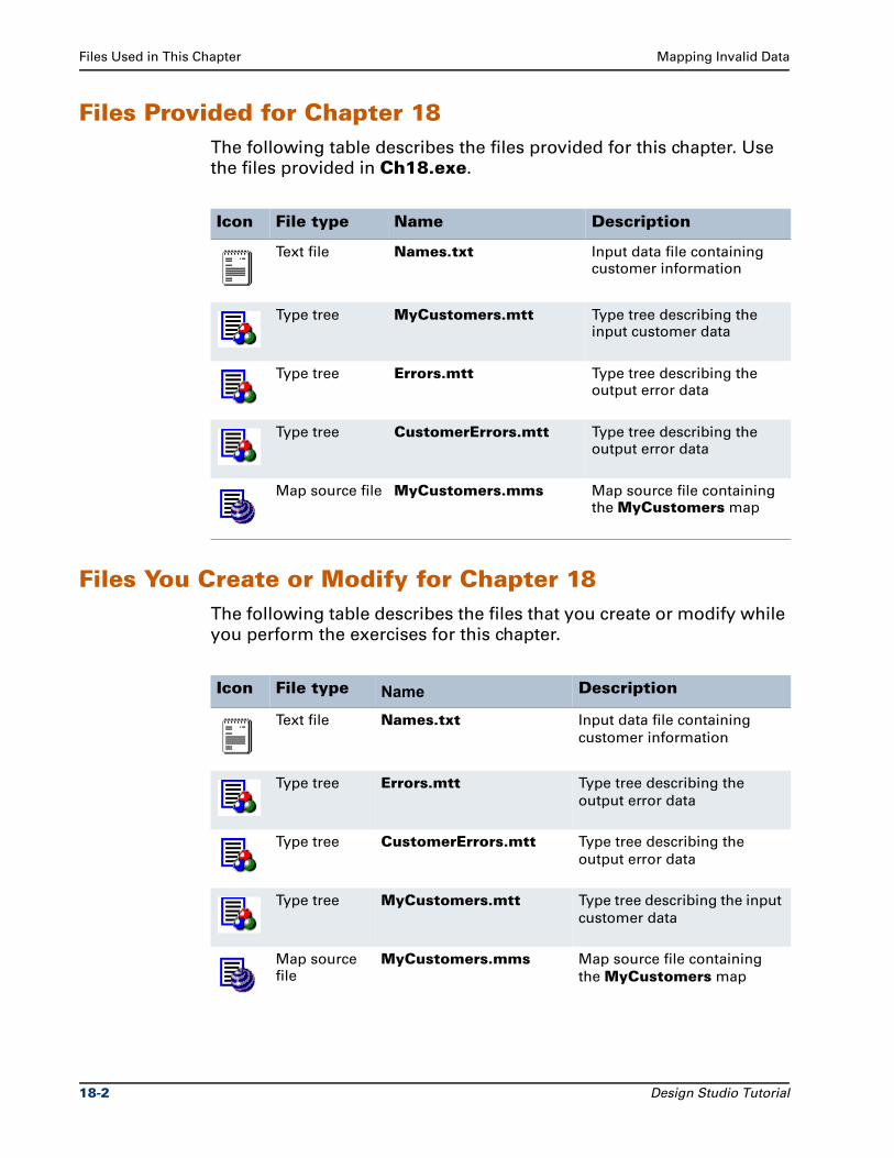
Files Used in This Chapter Mapping Invalid Data
Files Provided for Chapter 18The following table describes the files provided for this chapter. Use
the files provided in Ch18.exe.
Files You Create or Modify for Chapter 18The following table describes the files that you create or modify while
you perform the exercises for this chapter.
Icon File type Name Description
Text file Names.txt Input data file containing customer information
Type tree MyCustomers.mtt Type tree describing the input customer data
Type tree Errors.mtt Type tree describing the output error data
Type tree CustomerErrors.mtt Type tree describing the output error data
Map source file MyCustomers.mms Map source file containing the MyCustomers map
Icon File type Name Description
Text file Names.txt Input data file containing
customer information
Type tree Errors.mtt Type tree describing the
output error data
Type tree CustomerErrors.mtt Type tree describing the
output error data
Type tree MyCustomers.mtt Type tree describing the input
customer data
Map source file
MyCustomers.mms Map source file containing
the MyCustomers map
18-2 Design Studio Tutorial
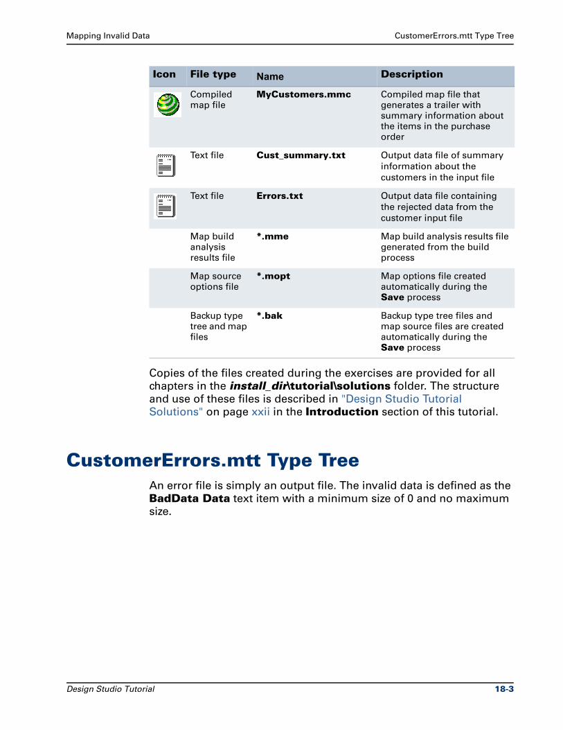
Mapping Invalid Data CustomerErrors.mtt Type Tree
Copies of the files created during the exercises are provided for all
chapters in the install_dir\tutorial\solutions folder. The structure
and use of these files is described in "Design Studio Tutorial
Solutions" on page xxii in the Introduction section of this tutorial.
CustomerErrors.mtt Type TreeAn error file is simply an output file. The invalid data is defined as the
BadData Data text item with a minimum size of 0 and no maximum
size.
Compiled map file
MyCustomers.mmc Compiled map file that generates a trailer with summary information about the items in the purchase order
Text file Cust_summary.txt Output data file of summary
information about the
customers in the input file
Text file Errors.txt Output data file containing
the rejected data from the
customer input file
Map build analysis results file
*.mme Map build analysis results file generated from the build process
Map source options file
*.mopt Map options file created automatically during the Save process
Backup type tree and map files
*.bak Backup type tree files and map source files are created automatically during the Save process
Icon File type Name Description
Design Studio Tutorial 18-3

Restart Attribute Mapping Invalid Data
This BadData item type is used to map an invalid customer.
The ErrorReport group type contains a Header and some unknown
number of BadData items as components.
Restart AttributeThe restart attribute is used to identify valid data objects that contain
objects in error.
18-4 Design Studio Tutorial
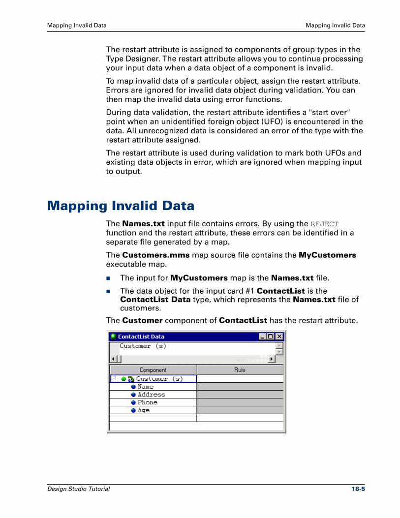
Mapping Invalid Data Mapping Invalid Data
The restart attribute is assigned to components of group types in the
Type Designer. The restart attribute allows you to continue processing
your input data when a data object of a component is invalid.
To map invalid data of a particular object, assign the restart attribute.
Errors are ignored for invalid data object during validation. You can
then map the invalid data using error functions.
During data validation, the restart attribute identifies a "start over"
point when an unidentified foreign object (UFO) is encountered in the
data. All unrecognized data is considered an error of the type with the
restart attribute assigned.
The restart attribute is used during validation to mark both UFOs and
existing data objects in error, which are ignored when mapping input
to output.
Mapping Invalid DataThe Names.txt input file contains errors. By using the REJECT
function and the restart attribute, these errors can be identified in a
separate file generated by a map.
The Customers.mms map source file contains the MyCustomers
executable map.
The input for MyCustomers map is the Names.txt file.
The data object for the input card #1 ContactList is the ContactList Data type, which represents the Names.txt file of customers.
The Customer component of ContactList has the restart attribute.
Design Studio Tutorial 18-5
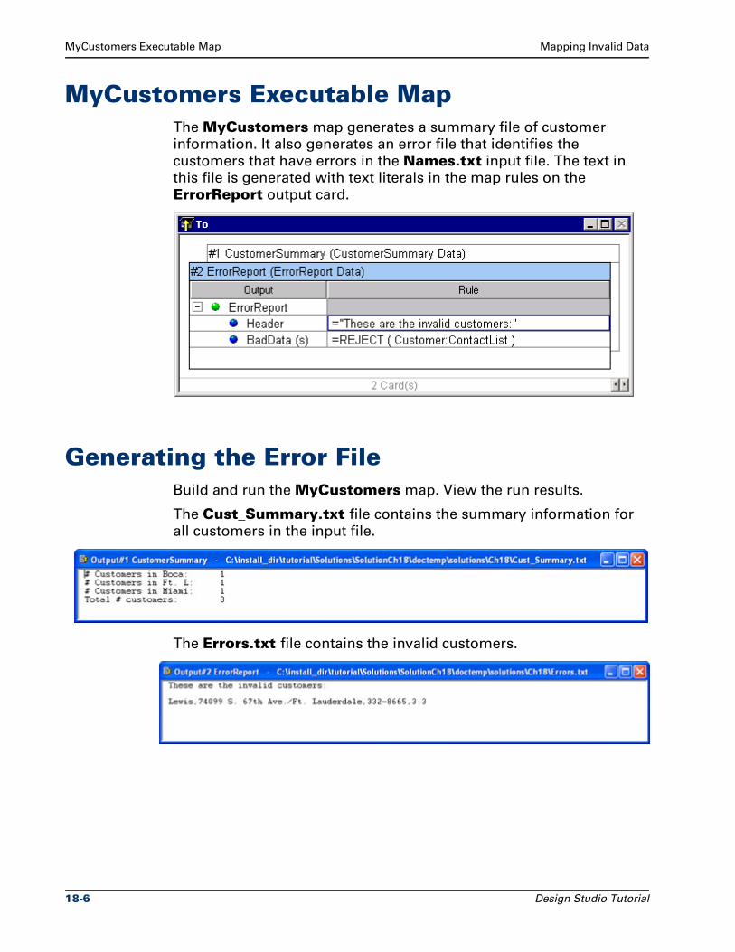
MyCustomers Executable Map Mapping Invalid Data
MyCustomers Executable MapThe MyCustomers map generates a summary file of customer
information. It also generates an error file that identifies the
customers that have errors in the Names.txt input file. The text in
this file is generated with text literals in the map rules on the
ErrorReport output card.
Generating the Error FileBuild and run the MyCustomers map. View the run results.
The Cust_Summary.txt file contains the summary information for
all customers in the input file.
The Errors.txt file contains the invalid customers.
18-6 Design Studio Tutorial
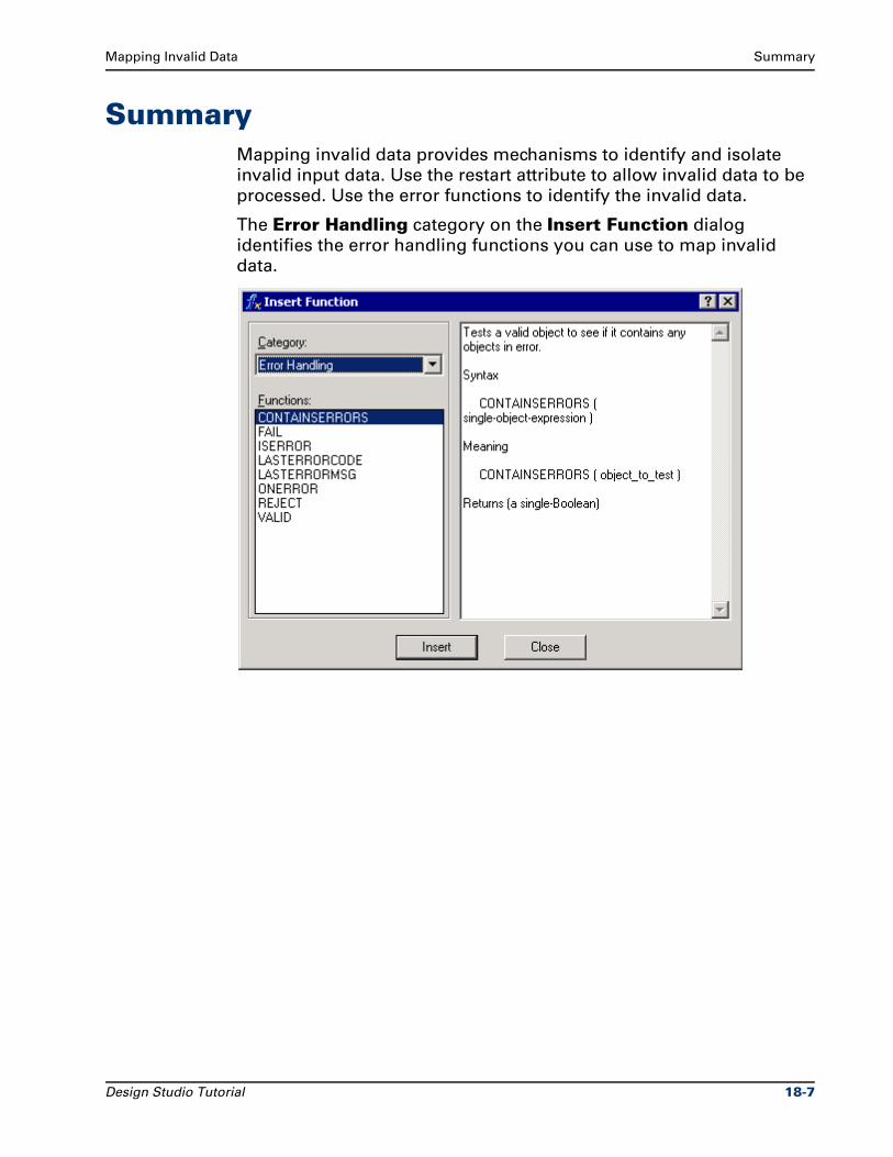
Mapping Invalid Data Summary
SummaryMapping invalid data provides mechanisms to identify and isolate
invalid input data. Use the restart attribute to allow invalid data to be
processed. Use the error functions to identify the invalid data.
The Error Handling category on the Insert Function dialog
identifies the error handling functions you can use to map invalid
data.
Design Studio Tutorial 18-7

Summary Mapping Invalid Data
18-8 Design Studio Tutorial

19Incrementing Output Data
Output objects can be incremented. There are three methods of
incrementing the position of an output object.
ObjectivesThis chapter provides an overview of the three methods of
incrementing the position of an output object.
By completing the exercises for Chapter 19, you run maps that:
Increment output objects using the INDEX function.
Increment output objects using the COUNT function.
Increment output objects using the index value [LAST].
Files Used in This ChapterYou will be working in the ..\tutorial\my_exercises\ch 19 folder.
Design Studio Tutorial 19-1
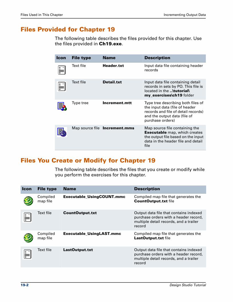
Files Used in This Chapter Incrementing Output Data
Files Provided for Chapter 19The following table describes the files provided for this chapter. Use
the files provided in Ch19.exe.
Files You Create or Modify for Chapter 19The following table describes the files that you create or modify while
you perform the exercises for this chapter.
Icon File type Name Description
Text file Header.txt Input data file containing header records
Text file Detail.txt Input data file containing detail records in sets by PO. This file is located in the ..\tutorial\ my_exercises\ch19 folder
Type tree Increment.mtt Type tree describing both files of the input data (file of header records and file of detail records) and the output data (file of purchase orders)
Map source file Increment.mms Map source file containing the Executable map, which creates the output file based on the input data in the header file and detail file
Icon File type Name Description
Compiled map file
Executable_UsingCOUNT.mmc Compiled map file that generates the CountOutput.txt file
Text file CountOutput.txt Output data file that contains indexed purchase orders with a header record, multiple detail records, and a trailer record
Compiled map file
Executable_UsingLAST.mmc Compiled map file that generates the LastOutput.txt file
Text file LastOutput.txt Output data file that contains indexed purchase orders with a header record, multiple detail records, and a trailer record
19-2 Design Studio Tutorial
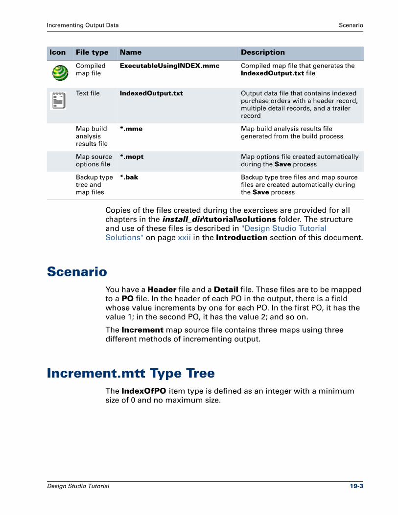
Incrementing Output Data Scenario
Copies of the files created during the exercises are provided for all
chapters in the install_dir\tutorial\solutions folder. The structure
and use of these files is described in "Design Studio Tutorial
Solutions" on page xxii in the Introduction section of this document.
ScenarioYou have a Header file and a Detail file. These files are to be mapped
to a PO file. In the header of each PO in the output, there is a field
whose value increments by one for each PO. In the first PO, it has the
value 1; in the second PO, it has the value 2; and so on.
The Increment map source file contains three maps using three
different methods of incrementing output.
Increment.mtt Type TreeThe IndexOfPO item type is defined as an integer with a minimum
size of 0 and no maximum size.
Compiled map file
ExecutableUsingINDEX.mmc Compiled map file that generates the IndexedOutput.txt file
Text file IndexedOutput.txt Output data file that contains indexed purchase orders with a header record, multiple detail records, and a trailer record
Map build analysis results file
*.mme Map build analysis results file generated from the build process
Map source options file
*.mopt Map options file created automatically during the Save process
Backup type tree and map files
*.bak Backup type tree files and map source files are created automatically during the Save process
Icon File type Name Description
Design Studio Tutorial 19-3
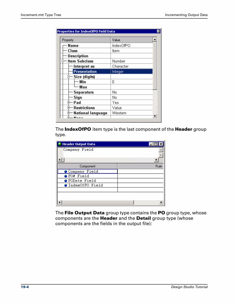
Increment.mtt Type Tree Incrementing Output Data
The IndexOfPO item type is the last component of the Header group
type.
The File Output Data group type contains the PO group type, whose
components are the Header and the Detail group type (whose
components are the fields in the output file):
19-4 Design Studio Tutorial
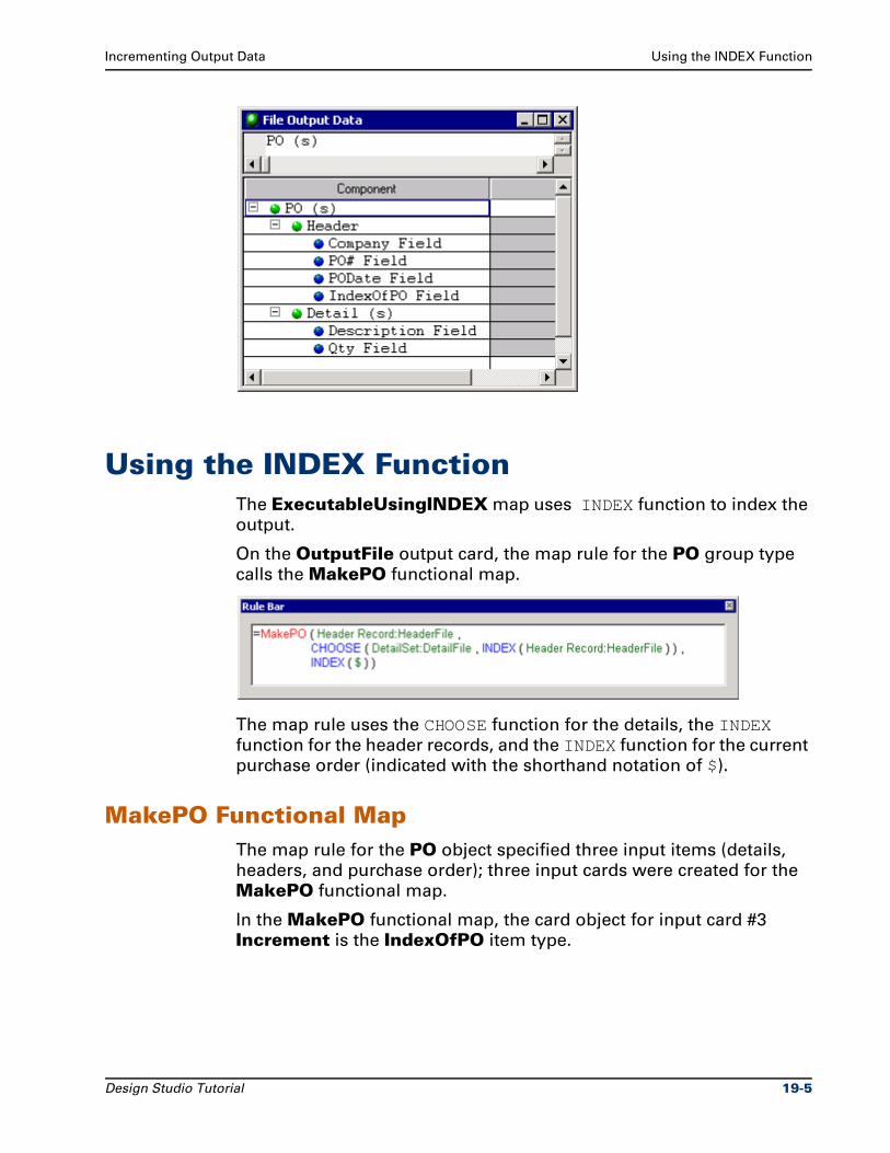
Incrementing Output Data Using the INDEX Function
Using the INDEX FunctionThe ExecutableUsingINDEX map uses INDEX function to index the
output.
On the OutputFile output card, the map rule for the PO group type
calls the MakePO functional map.
The map rule uses the CHOOSE function for the details, the INDEX
function for the header records, and the INDEX function for the current
purchase order (indicated with the shorthand notation of $).
MakePO Functional MapThe map rule for the PO object specified three input items (details,
headers, and purchase order); three input cards were created for the
MakePO functional map.
In the MakePO functional map, the card object for input card #3
Increment is the IndexOfPO item type.
Design Studio Tutorial 19-5
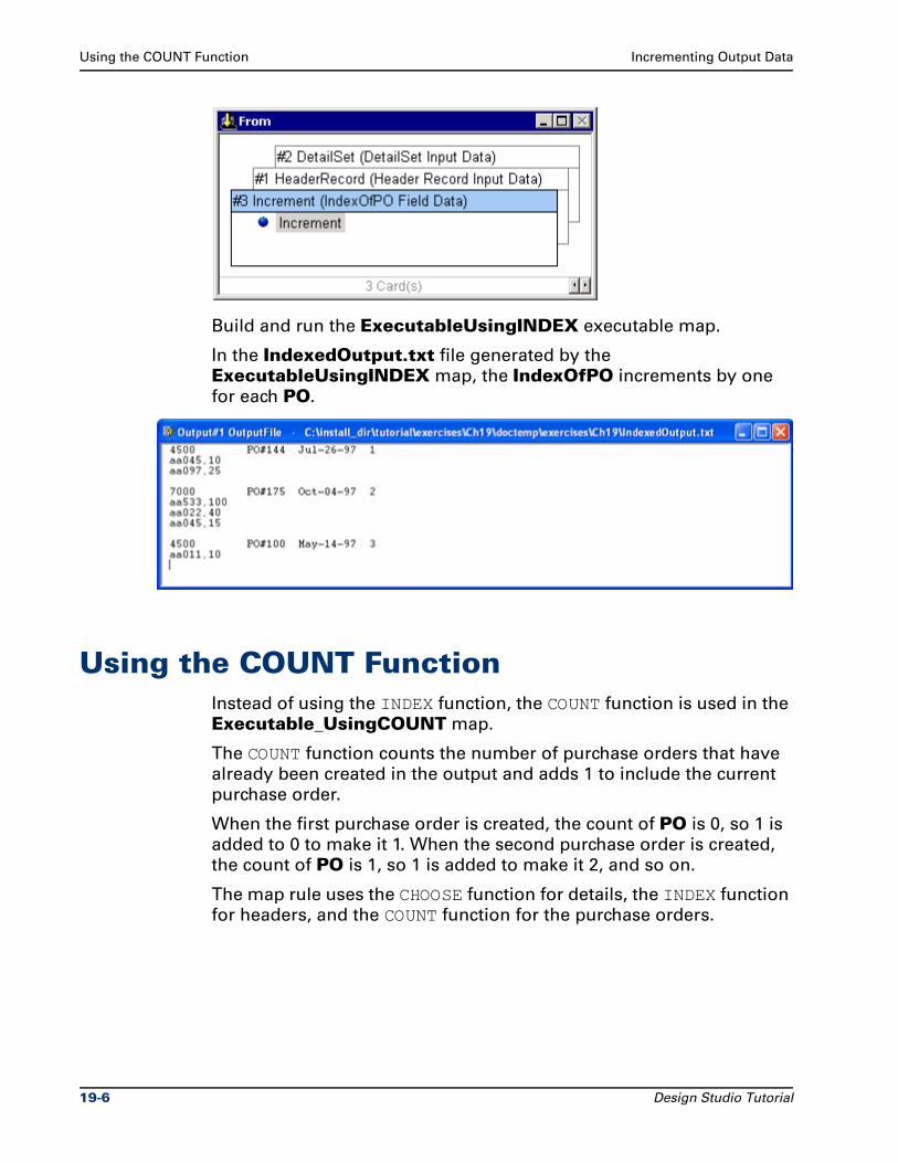
Using the COUNT Function Incrementing Output Data
Build and run the ExecutableUsingINDEX executable map.
In the IndexedOutput.txt file generated by the
ExecutableUsingINDEX map, the IndexOfPO increments by one
for each PO.
Using the COUNT FunctionInstead of using the INDEX function, the COUNT function is used in the
Executable_UsingCOUNT map.
The COUNT function counts the number of purchase orders that have
already been created in the output and adds 1 to include the current
purchase order.
When the first purchase order is created, the count of PO is 0, so 1 is
added to 0 to make it 1. When the second purchase order is created,
the count of PO is 1, so 1 is added to make it 2, and so on.
The map rule uses the CHOOSE function for details, the INDEX function
for headers, and the COUNT function for the purchase orders.
19-6 Design Studio Tutorial
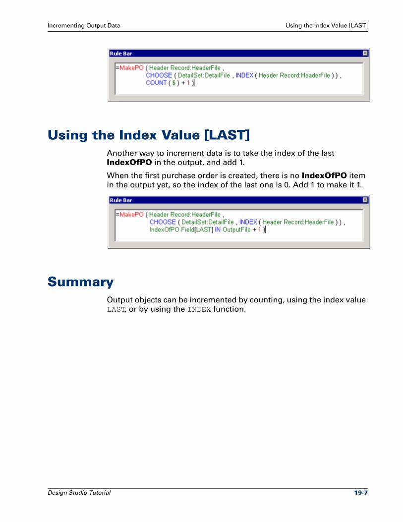
Incrementing Output Data Using the Index Value [LAST]
Using the Index Value [LAST]Another way to increment data is to take the index of the last
IndexOfPO in the output, and add 1.
When the first purchase order is created, there is no IndexOfPO item
in the output yet, so the index of the last one is 0. Add 1 to make it 1.
SummaryOutput objects can be incremented by counting, using the index value
LAST, or by using the INDEX function.
Design Studio Tutorial 19-7

Summary Incrementing Output Data
19-8 Design Studio Tutorial
20Creating a Validation Map
Validation maps provide a method of confirming your input type
definitions are accurate. Validation maps are used when you are
developing type trees.
ObjectivesThis chapter provides an overview of creating a validation map.
By completing the exercises for Chapter 20, you will learn to:
Create a map to validate your type definitions.
Files Used in This ChapterYou will be working in the ..\tutorial\my_exercises\ch20 folder.
Files Provided for Chapter 20The following table describes the files provided for this chapter. Use
the files provided in Ch20.exe.
Icon File type Name Description
Text file Contact.txt Input data text file that contains a single contact record of information about one customer
Design Studio Tutorial 20-1
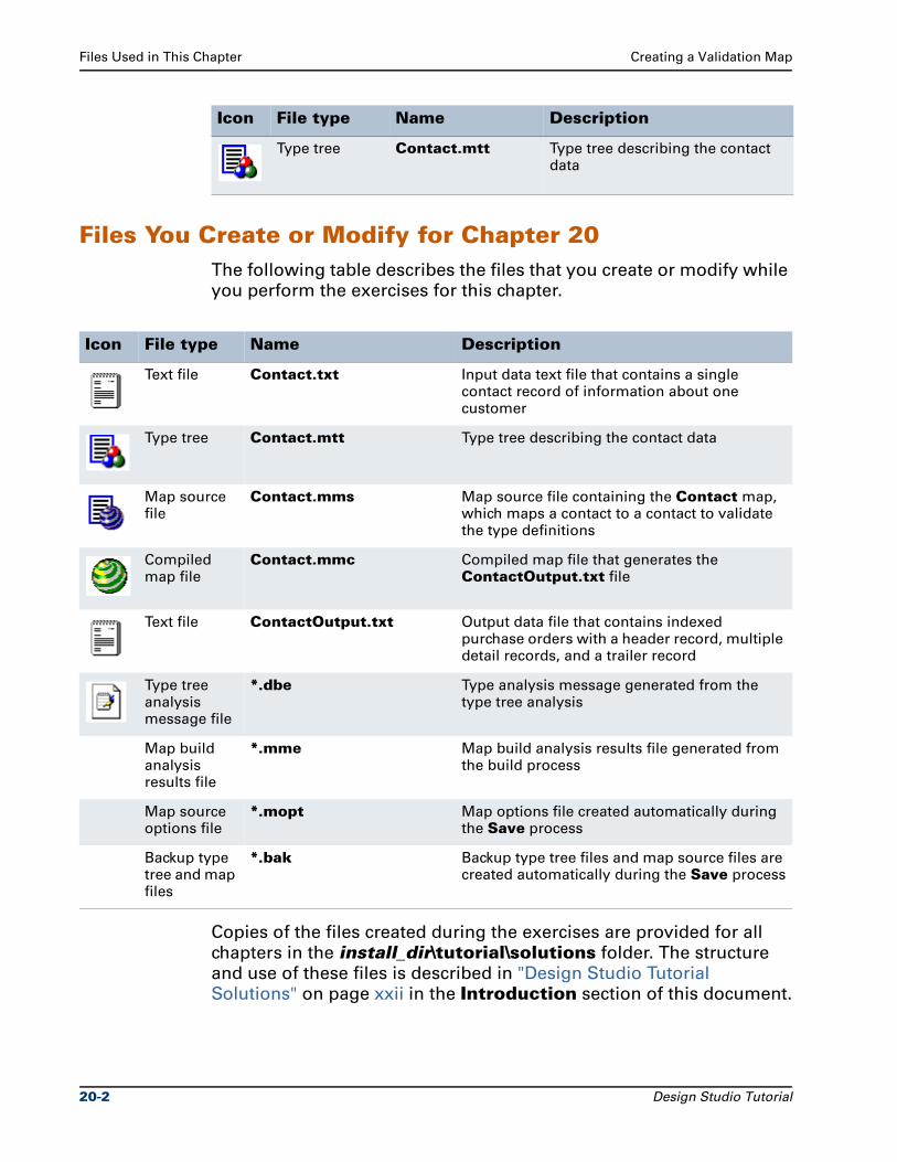
Files Used in This Chapter Creating a Validation Map
Files You Create or Modify for Chapter 20The following table describes the files that you create or modify while
you perform the exercises for this chapter.
Copies of the files created during the exercises are provided for all
chapters in the install_dir\tutorial\solutions folder. The structure
and use of these files is described in "Design Studio Tutorial
Solutions" on page xxii in the Introduction section of this document.
Type tree Contact.mtt Type tree describing the contact data
Icon File type Name Description
Icon File type Name Description
Text file Contact.txt Input data text file that contains a single contact record of information about one customer
Type tree Contact.mtt Type tree describing the contact data
Map source file
Contact.mms Map source file containing the Contact map, which maps a contact to a contact to validate the type definitions
Compiled map file
Contact.mmc Compiled map file that generates the ContactOutput.txt file
Text file ContactOutput.txt Output data file that contains indexed purchase orders with a header record, multiple detail records, and a trailer record
Type tree analysis message file
*.dbe Type analysis message generated from the type tree analysis
Map build analysis results file
*.mme Map build analysis results file generated from the build process
Map source options file
*.mopt Map options file created automatically during the Save process
Backup type tree and map files
*.bak Backup type tree files and map source files are created automatically during the Save process
20-2 Design Studio Tutorial
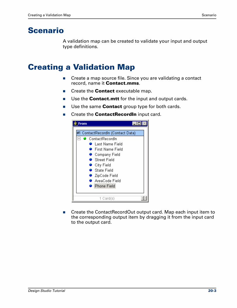
Creating a Validation Map Scenario
ScenarioA validation map can be created to validate your input and output
type definitions.
Creating a Validation MapCreate a map source file. Since you are validating a contact record, name it Contact.mms.
Create the Contact executable map.
Use the Contact.mtt for the input and output cards.
Use the same Contact group type for both cards.
Create the ContactRecordIn input card.
Create the ContactRecordOut output card. Map each input item to the corresponding output item by dragging it from the input card to the output card.
Design Studio Tutorial 20-3
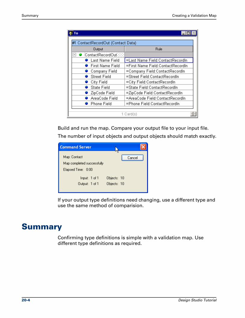
Summary Creating a Validation Map
Build and run the map. Compare your output file to your input file.
The number of input objects and output objects should match exactly.
If your output type definitions need changing, use a different type and
use the same method of comparision.
SummaryConfirming type definitions is simple with a validation map. Use
different type definitions as required.
20-4 Design Studio Tutorial
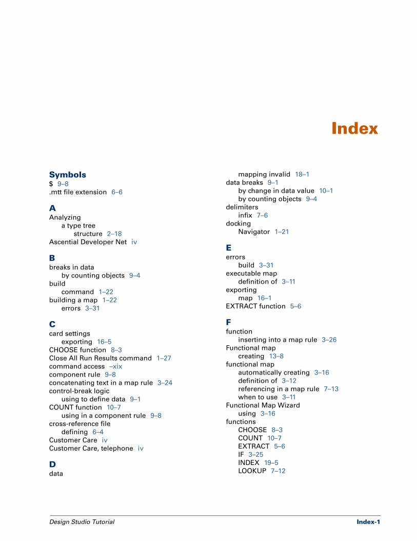
Index
Symbols$ 9–8
.mtt file extension 6–6
AAnalyzing
a type tree
structure 2–18
Ascential Developer Net iv
Bbreaks in data
by counting objects 9–4
build
command 1–22
building a map 1–22
errors 3–31
Ccard settings
exporting 16–5
CHOOSE function 8–3
Close All Run Results command 1–27
command access –xix
component rule 9–8
concatenating text in a map rule 3–24
control-break logic
using to define data 9–1
COUNT function 10–7
using in a component rule 9–8
cross-reference file
defining 6–4
Customer Care iv
Customer Care, telephone iv
Ddata
Design Studio Tutorial
mapping invalid 18–1
data breaks 9–1
by change in data value 10–1
by counting objects 9–4
delimiters
infix 7–6
docking
Navigator 1–21
Eerrors
build 3–31
executable map
definition of 3–11
exporting
map 16–1
EXTRACT function 5–6
Ffunction
inserting into a map rule 3–26
Functional map
creating 13–8
functional map
automatically creating 3–16
definition of 3–12
referencing in a map rule 7–13
when to use 3–11
Functional Map Wizard
using 3–16
functions
CHOOSE 8–3
COUNT 10–7
EXTRACT 5–6
IF 3–25
INDEX 19–5
LOOKUP 7–12
Index-1
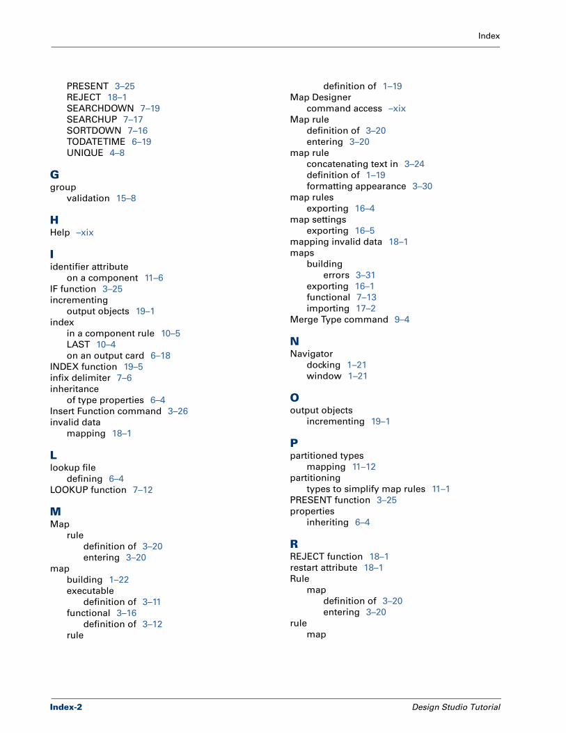
Index
PRESENT 3–25
REJECT 18–1
SEARCHDOWN 7–19
SEARCHUP 7–17
SORTDOWN 7–16
TODATETIME 6–19
UNIQUE 4–8
Ggroup
validation 15–8
HHelp –xix
Iidentifier attribute
on a component 11–6
IF function 3–25
incrementing
output objects 19–1
index
in a component rule 10–5
LAST 10–4
on an output card 6–18
INDEX function 19–5
infix delimiter 7–6
inheritance
of type properties 6–4
Insert Function command 3–26
invalid data
mapping 18–1
Llookup file
defining 6–4
LOOKUP function 7–12
MMap
rule
definition of 3–20
entering 3–20
map
building 1–22
executable
definition of 3–11
functional 3–16
definition of 3–12
rule
Index-2
definition of 1–19
Map Designer
command access –xix
Map rule
definition of 3–20
entering 3–20
map rule
concatenating text in 3–24
definition of 1–19
formatting appearance 3–30
map rules
exporting 16–4
map settings
exporting 16–5
mapping invalid data 18–1
maps
building
errors 3–31
exporting 16–1
functional 7–13
importing 17–2
Merge Type command 9–4
NNavigator
docking 1–21
window 1–21
Ooutput objects
incrementing 19–1
Ppartitioned types
mapping 11–12
partitioning
types to simplify map rules 11–1
PRESENT function 3–25
properties
inheriting 6–4
RREJECT function 18–1
restart attribute 18–1
Rule
map
definition of 3–20
entering 3–20
rule
map
Design Studio Tutorial
Index
definition of 1–19
rule bar
creating new line in 3–30
run results 1–25
command 3–32
viewing 3–32
SSEARCHDOWN function 7–19
SEARCHUP function 7–17
shorthand notation in a component rule
$ 9–8
SORTDOWN function 7–16
Structure
analyzing in type definitions 2–18
Ttext
concatenating in a map rule 3–24
entering in a map rule 3–24
TODATETIME function 6–19
trace file 15–1, 15–3
viewing 15–5
Type
creating groups 6–7
definitions
analyzing 2–18
type
inheritance 6–4
partitioned
mapping 11–12
UUNIQUE function 4–8
Vviewing
run results 1–25, 3–32
trace file 15–5
Wwizard
using the Functional Map Wizard 3–16
XXML
format for maps and map rules 16–2
Design Studio Tutorial
Index-3
Index
Index-4
Design Studio Tutorial