Embed Size (px)
Citation preview

ASC Z223 NFPA 54
COMMITTEE ON NATIONAL FUEL GAS CODE
AGENDA
ASC Z223 / NFPA 54 Second Draft
National Fuel Gas Code Committee
Embassy Suites by Hilton Phoenix Biltmore
Phoenix, AZ
June 21-22, 2016
Tuesday, June 21, 2016
8:00 a.m. ............................ Continental Breakfast
8:30 a.m. – 5:00 p.m. ........ Committee Discussions
1. Call to Order, Self-Introductions, Registration List
2. Adoption of Agenda – Changes / Additions
3. Announcements: Antitrust Guidelines and Fire Exits and Alarm
4. Membership Review
a. ASC Z223 Committee Updates - Roster Review
b. NFPA 54 Committee Updates – Roster Review
5. Approval of October 2015 Committee Meeting Minutes
6. Future Meeting Schedule
7. Results of ANSI Audit on ASC Z223
8. Consideration of Public Comments
12:00 p.m. ........................ Lunch hosted by NFPA
1:00 p.m. – 1:30 p.m. ........ Presentation - Odorization Refresher
6:00 p.m. – 7:00 p.m. ........ Reception Hosted by the American Gas Association
Wednesday, June 22, 2016 8:00 a.m... .......................... Continental Breakfast
8:30 a.m. – 5:00 p.m. ........ Committee Discussions
9. Continued – Consideration of Public Comments
10. New Business
11. Adjourn

ASC Z223 NFPA 54 COMMITTEE ON NATIONAL FUEL GAS CODE
DRAFT COMMITTEE MINUTES October 13-15, 2015
APPROVAL PENDING
.

ASC Z223 NFPA 54 COMMITTEE ON NATIONAL FUEL GAS CODE
Draft 11/23/15
Minutes ASC Z223 / NFPA 54
National Fuel Gas Code Committee Hyatt Regency San Francisco Airport
San Francisco, CA October 13-15, 2015
1. Call to Order, Self-Introductions & Attendance: Chair, Tom Crane, called the meeting to order
and members and guests introduced themselves. (Attachment A).
2. Adoption of Agenda: The agenda was approved as distributed.
3. Announcements: Participants were made aware of the fire alarms/exists and the AGA and NFPA antitrust guidelines.
4. Membership Review: a. ASC Z223 Committee Updates – The membership roster and interest category balance was
reviewed. The committee is in balance in accordance with its operating procedures. The Secretary will be asking NFPA 54 members, not currently on the ASC Z223, to consider joining the committee and will conduct a letter ballot for those members. Membership on both committees help coordinate the two committee activities and help ensure that AGA and NFPA publish consistent code versions.
b. NFPA 54 Committee Updates – The membership roster was reviewed. The NFPA Standards Council is responsible for maintaining committee balance and was noted that it is in balance.
5. Approval of Committee Meeting Minutes: The November 2014 full committee and September 2015 Advisory Panel minutes were approved as distributed.
6. Future Meeting Schedule: The proposed 2016 - 2017 meeting schedule was reviewed without changes (Attachment B).
7. NFPA Revised Process and NFPA Research Foundation Presentation: Laura Montville provided an overview of the revised NFPA process and the NFPA Research Foundation.
8. Consideration of Public Input and Committee Input: The committee reviewed and took action on the public input considering the advisory panel recommendations. The committee actions will be the standing action (Summary - Attachment C) on the letter ballot scheduled to be conducted early January 2016. Approved actions will form the first revision draft and will be placed out for public review.
9. Task Group Report: The Biogas Task Group’s charge is to determine if the scope of the NFGC could be expanded to include piping systems and equipment designed for use with biogases. The NFGC Task Group members are Swiecicki (Chair), Caudle, Gress, and Holmes. The Task Group submitted a research project request (Attachment D) to the NFPA Research Foundation seeking funding. The request is to determine the current “sate of the art” with respect to biogas quality standards used around the world. The Foundation ranks all such requests from NFPA project committees and that ranking determines if a project gets funding. The Biogas request did not receive a high enough ranking to receive funding. The Biogas Task Group will remain active for future activities.

ASC Z223 NFPA 54 COMMITTEE ON NATIONAL FUEL GAS CODE
Draft 11/23/15
10. Other Actions:
a. A Pressure Definition Task Group was created to address the various “pressure” definitions and determine how the NFGC can best define the pressures defined within the NFGC. Members are: Mike Gorham (Chair), David Berning, Ted Lemoff, and Franklin Switzer. The task group is requested to consider public inputs No. 189, 188, 190, and 191 as part of their task.
b. Staff is requested to provide the reissued GTI CSST report (Oct 12, 2015, rev-A) to the committee. This report replaces the September 2013 version, which was posted on the NFPA 54 website. The reissued report corrects typographical errors within two data tables and does not alter the report’s findings. Secretary Note: The reissued report is available on the NFPA 54 website.
c. The Equipment Panel’s recommendation to revise their panel name to the Appliance Panel was approved.
d. One new agenda item is added to the Appliance Panel agenda. A review of the term “permanent” in regards “opening” in chapter 9’s combustion opening coverage to determine if a clarification is needed for openings equipped with adjustable and fixed louvers.
11. Adjourn: With business completed, the committee adjourned on October 18th at 12:07 p.m.
ATTACHMENT A - Attendance List1
National Fuel Gas Code Committee Hyatt Regency San Francisco Airport
San Francisco, CA October 13-15, 2015
Members2
Name, Representing Hugo Aguilar, IAPMO Stephen Abernathy, American Gas Association David Berning, Intertek Testing Services James Brewer, National Chimney Sweep Guild Paul Cabot, American Gas Association Shannon Corcoran, CSA Group Thomas Crane, Crane Engineering Kody Daniel, Property Casualty Insurers Association Gerald Davis, American Gas Association Glen Edgar, VenTech Consulting Alberto Fossa, NFPA Latin American Section Pennie Feehan, Copper Development Association Mike Gorham, National Propane Gas Assoc. Gregg Gress, International Code Council Steen Hagensen, ENERVEX
Peter Holmes, Maine Fuel Board Marek Kulik, Tech. Standards & Safety Authority Theodore Lemoff, Consultant James Osterhaus, Railroad Commission of Texas Andrea Papageorge, American Gas Association Phillip Ribbs, CA State Pipe Trades Council John Scanlon, AHRI Peter Swim, Whirlpool Corporation Thomas Stroud, HPBA Franklin Switzer, S-afe Inc. John Scanlon, AHRI Eric Smith, International Fire Marshals Assocation Bruce Swiecicki, National Propane Gas Assocation Matthew Wilber, Crane Engineering
NFPA Staff - Laura Montville
Guests Name, Organization
Gaetano Altomare, IPEX, Inc. Johnathan Brania, Underwriters Laboratories Guy Colonna, National Fire Protection Assoc. Curtis Dady, Viega, LLC David Edler, Ward Manufacturing Mark Fasel, Viega, LLC Larry Gill, IPEX USA LLC Bandar Hamada, A.O. Smith
Mark Harris, Titeflex Corporation James Molloy, Centrotherm James Ranfone, American Gas Association Joseph Rose, Southern California Gas Co. Frank Stanonik, AHRI Michael Stringfellow, PowerCET Corp. Robert Torbin, Omega Flex Art Weirauch, Omega Flex
1 Attended all or part of the committee meeting, sign in sheet can be obtained from the Secretary. 2 Voting and alternate members of NFPA 54 and ASC Z223


DATE: September 25, 2015
SUBJECT: 2015-2017 Meetings: ASC Z223/NFPA 54 Committee
The ASC Z223 and NFPA 54 committees meet jointly to maintain and develop the National Fuel Gas Code. For your planning purposes the National Fuel Gas Code Committee’s 2015-2017 preliminary meeting schedule is proposed as follows:
2018 EDITION: PUBLIC INPUT DUE BY JULY 6, 2015
Date: ...................September 14-17, 2015 (Monday-Thursday) Meeting Type: ....Advisory Panel Meetings Purpose:..............Review and make recommendations on Public Input and complete
assigned committee proposals Location .............To Be Determined Host: ...................National Fire Protection Association
Date: ...................October 13-15, 2015 (Tuesday-Thursday) Meeting Type: ....Full Committee Purpose:..............Take action on Public Input and Committee Proposals Location .............San Francisco, CA Host: ...................American Gas Association
2018 EDITION: PUBLIC COMMENTS DUE BY MAY 16, 2016
Date: ...................June 21-23, 2016 (Tuesday-Thursday) Meeting Type: ....Full Committee Purpose:..............Take action on Public Comments Location .............To Be Determined Host: ...................National Fire Protection Association
2018 EDITION: PUBLISHED OCTOBER 2017
Date: ...................November 14-15, 2017 (Tuesday-Wednesday) Meeting Type: ....Full Committee Purpose:..............Complete Unfinished Business &Planning on 2021 Edition Location .............To Be Determined Host: ...................American Gas Association
Timely meeting notices will be sent to you as each meeting date approaches. Meeting information will also be available on the AGA and NFPA websites. Please contact Paul Cabot with any questions or comments you may have at 202.824.7312 or [email protected].
Attachment B


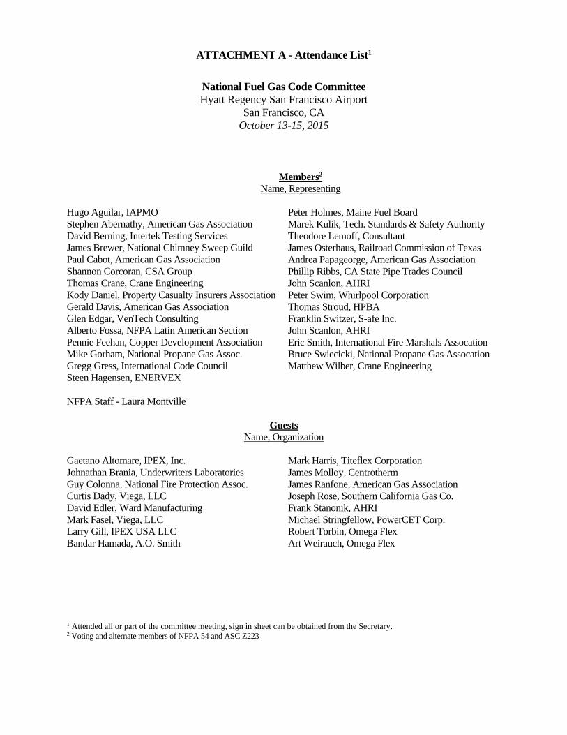
ATTACHMENT C SUMMARY LIST OF COMMITTEE ACTIONS ON PUBLIC INPUT, COMMITTEE
GENERATED FRIST REVISIONS, AND COMMITTEE INPUT (PENDING LETTER BALLOT APPROVAL)
11/19/15
1 CI = Committee Input; CFR = Committee Generated First Revision; PI = Public Input; PFR = Draft Panel Frist Revision 2 Action as determine at meeting. Final action is subject to committee letter ballot. FR = First Revision based on PI or CI; Resolve = No first revision created; NA = Panel proposal not accepted by the committee.
Item1 Section Action2 Notes
Global:
CI Global CI 78
The committee is requesting comments on the appropriate use of the terms “listed and labeled,” “listed in accordance with,” “in compliance with,” and “listed to” as used throughout the code. The boiler plate definition for “listed” and “labeled” should examined to determine if it is appropriate to the usage within this code.
CI Global CI 87 Extracts from NFPA documents will be updated at the second draft stage when the new editions have been issued.
Chapter 1:
PI 2 [Global] Resolve
PI 53 [1.1.1.1(B)] Resolve
PI 54 [1.1.1.1(B)] FR 61
CFR [1.1.1.2] FR 54
Chapter 2:
PI 3 [2.3] Resolve
CFR [2.3] FR 92-95
Staff is requested to update the standard edition years and do not include addendum editions.
PI 161 [2.3.5] FR 25
PI 45 [2.3.5] FR 25
Chapter 3:
PI 43 [3.3.25] Resolve
PI 187 [3.3.28] Resolve
PI 91 [3.3.48] FR 3
PI 95 [3.3.63] Resolve
PI 97 [3.3.66] FR 62
PI 134 [3.3.72 New] Resolve
PI 74 [3.3.75] Resolve
CFR [3.3.75] FR 4

ATTACHMENT C SUMMARY LIST OF COMMITTEE ACTIONS ON PUBLIC INPUT, COMMITTEE
GENERATED FRIST REVISIONS, AND COMMITTEE INPUT (PENDING LETTER BALLOT APPROVAL)
11/19/15
1 CI = Committee Input; CFR = Committee Generated First Revision; PI = Public Input; PFR = Draft Panel Frist Revision 2 Action as determine at meeting. Final action is subject to committee letter ballot. FR = First Revision based on PI or CI; Resolve = No first revision created; NA = Panel proposal not accepted by the committee.
Item1 Section Action2 Notes
PI 75 [3.3.77] FR 40
PI 190 [3.3.78] Resolve
PI 188 [3.3.78.3] Resolve
PI 189 [3.3.78.4] Resolve
PI 14 [3.3.84.4] FR 81
PI 98 [3.3.86] FR 41
Chapter 4:
PI 101 [4.4] Resolve
Chapter 5:
PI 119 [5.1.1] Resolve
PI 102 [5.1.2.2] FR 6
PI 103 [5.4.3] FR 7
PI 104 [5.4.4] Resolve
PI 191 [5.5.1] Resolve
PI 55 [5.5.1] FR 12
CFR [5.5.2] FR 90 This changed the title to “Low Temperature LP-Gas Systems” (also, 5.5.2 is now 5.5.5 due to changes in FR 12)
CI [5.6.2.2, 5.6.8.1] CI 91 Request public comment to add coverage for Schedule 10 steel pipe and press-connect fittings. Also see CI 63 [5.6.8.1]
PI 133 [5.6.4.1.2 New] Resolve
CI [5.6.4.1.2] CI 88 Request public comment on if and when the ASTM D2145 Standard covering polyamide plastic piping will be approved for code adoption.
CFR [5.6.6] FR 65 Also see FR to section 7.2.2.
PI 13 [5.6.8.1] FR 20
PI 5 [5.6.8.1] FR 20
ATTACHMENT C SUMMARY LIST OF COMMITTEE ACTIONS ON PUBLIC INPUT, COMMITTEE
GENERATED FRIST REVISIONS, AND COMMITTEE INPUT (PENDING LETTER BALLOT APPROVAL)
11/19/15
1 CI = Committee Input; CFR = Committee Generated First Revision; PI = Public Input; PFR = Draft Panel Frist Revision 2 Action as determine at meeting. Final action is subject to committee letter ballot. FR = First Revision based on PI or CI; Resolve = No first revision created; NA = Panel proposal not accepted by the committee.
Item1 Section Action2 Notes
CI [5.6.8.1] CI 63 Request public comment to add coverage for Schedule 10 steel pipe and press-connect fittings. Also see CI 91 [5.6.2.2]
PI 192 [5.6.8.4] Resolve
PI 44 [5.6.8.4] FR 17
PI 193 [5.8.1] FR 21
PI 194 [5.9] Resolve
PI 195 [5.9.2.5] Resolve
PI 196 [5.9.3, 5.9.3.1, 5.9.4] FR 22
PI 22 [5.9.6] FR 23
Stainless Steel Schedule 40 and Tubing Related:
PI 112 [5.6.2.2] FR 13
CFR [5.6.3] FR 97
PI 113 [5.6.3.1] FR 14
PI 115 [5.6.8.2] FR 16
PI 114 [5.6.8.2] FR 15
PI 116 [5.6.8.4] FR 17
PI 131 [6.2] FR 18 Sizing tables will be renumbered.
PI 132 [6.3] FR 19 Sizing tables will be renumbered.
Chapter 6:
PI 51 [6.4.3 New] Resolve
Chapter 7:
PI 23 [7.1.6.2] FR 24
CFR [7.1.8 New] FR 83
CFR [7.2] FR 82
CFR [7.2.2] FR 65 Also see FR for section 5.6.6.
PI 105 [7.2.2.2] Resolve

ATTACHMENT C SUMMARY LIST OF COMMITTEE ACTIONS ON PUBLIC INPUT, COMMITTEE
GENERATED FRIST REVISIONS, AND COMMITTEE INPUT (PENDING LETTER BALLOT APPROVAL)
11/19/15
1 CI = Committee Input; CFR = Committee Generated First Revision; PI = Public Input; PFR = Draft Panel Frist Revision 2 Action as determine at meeting. Final action is subject to committee letter ballot. FR = First Revision based on PI or CI; Resolve = No first revision created; NA = Panel proposal not accepted by the committee.
Item1 Section Action2 Notes
PI 52 [7.3.5.1] Resolve
PI 24 [7.3.5.2] Resolve
PI 26 [7.3.5.2] Resolve
PI 12 [7.6] Resolve
PI 27 [7.8] FR 66
PI 80 [7.9.2 New] FR 67
PI 28 [7.10] FR 68
CSST Related:
PI 69 [5.6.3.4] Resolve
PFR [7.13.1] NA The committee did not approve the draft panel first revision (FR 9)
PI 62 [7.13.2] Resolve
PI 100 [7.13.2.5] FR 8
PI 144 [7.13.2] 211 Resolve
PI 70 [7.13.5 New] Resolve
PI 72 [7.13.6 New] Resolve
PI 66 [7.2.4] Resolve
PI 110 [7.13.3] Resolve
PI 146 [7.13.3 New] Resolve
PI 147 [7.13.3] Resolve
PI 59 [7.13.3 New] Resolve
PI 121 [7.13.2] FR 10
PI 145 [7.13.2.1] Resolve
PI 152 [7.13.2.1] Resolve
PI 159 [7.13.2.1] Resolve
PI 155 [7.13.2.3] Resolve
PI 157 [7.13.2.3] Resolve
PI 162 [7.13.2.3] Resolve
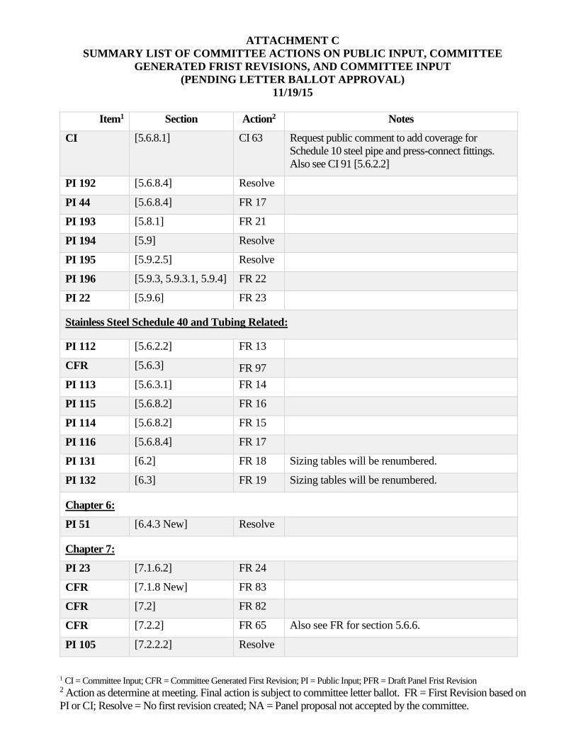
ATTACHMENT C SUMMARY LIST OF COMMITTEE ACTIONS ON PUBLIC INPUT, COMMITTEE
GENERATED FRIST REVISIONS, AND COMMITTEE INPUT (PENDING LETTER BALLOT APPROVAL)
11/19/15
1 CI = Committee Input; CFR = Committee Generated First Revision; PI = Public Input; PFR = Draft Panel Frist Revision 2 Action as determine at meeting. Final action is subject to committee letter ballot. FR = First Revision based on PI or CI; Resolve = No first revision created; NA = Panel proposal not accepted by the committee.
Item1 Section Action2 Notes
PI 19 [7.13.2.3] FR 11
PI 64 [7.13.2.4] Resolve
CFR [7.13.4] FR 69 The FR is for the NFPA published version.
PI 149 [A.7.13.2.1 New] Resolve
PI 153 [A.7.13.2.1 New] Resolve
PI 165 [A.7.13.2.1 New] Resolve
PI 150 [A.7.13.2.2 New] Resolve
PI 154 [A.7.13.2.2 New] Resolve
PI 164 [A.7.13.2.2 New] Resolve
PI 156 [A.7.13.2.3 New] Resolve PI 158 [A.7.13.2.3 New] Resolve PI 163 [A.7.13.2.3 New] Resolve
PI 111 [A.7.13.3 New] Resolve
PI 148 [A.7.13.3 New] Resolve
PI 151 [A.7.13.3 New] Resolve
PI 46 [Tables 6.2(o) - 6.2(q)] Resolve
PI 48 [Tables 6.3(h) - 6.2(j)] Resolve
Chapter 8:
PI 20 [8.1.1.1] Resolve
PI 21 [8.1.1.2] Resolve
PI 29 [8.1.2] FR 71
PI 73 [8.1.4.1, 8.1.4.2] Resolve
Chapter 9:
PI 106 [9.1.1.3] Resolve
PI 107 [9.1.8.2] Resolve
PI 122 [9.1.23] FR 58

ATTACHMENT C SUMMARY LIST OF COMMITTEE ACTIONS ON PUBLIC INPUT, COMMITTEE
GENERATED FRIST REVISIONS, AND COMMITTEE INPUT (PENDING LETTER BALLOT APPROVAL)
11/19/15
1 CI = Committee Input; CFR = Committee Generated First Revision; PI = Public Input; PFR = Draft Panel Frist Revision 2 Action as determine at meeting. Final action is subject to committee letter ballot. FR = First Revision based on PI or CI; Resolve = No first revision created; NA = Panel proposal not accepted by the committee.
Item1 Section Action2 Notes
PI 123 [9.1.24] Resolve
PI 58 [9.2.3] Resolve
PI 143 [9.3.1.1] Resolve
PI 126 [9.3.1.5] Resolve
PI 31 [9.3.1.5] Resolve
PI 30 [9.3.2] Resolve
PI 32 [9.3.2] Resolve
CI [9.3.2] CI 72 Staff is requested to contact ASHRAE to have the appropriate persons or committee provide a recommendation
PI 128 [9.3.2.3] FR 73
PI 142 [9.3.3.2] Resolve
CFR [9.6.1 (5)] FR 55
PI 33 [9.6.5.1] FR 43
CFR [9.6.5.3] FR 44
PFR [9.6.8] NA The committee did not approve the draft panel first revision (FR 47)
PI 34 [9.6.8] Resolve
Chapter 10:
PI 108 [10.1.1] Resolve
PI 76 [10.3.7.1] Resolve
PI 160 [10.4.4.3] FR 48
PI 35 [10.8.3.2] Resolve
CFR [10.8.3.2] FR 75
PI 36 [10.9.3] FR 76
PI 38 [10.22.1.1 New] FR 49
PI 37 [10.22.1] Resolve The committee did not accept the panel recommendation to create a first revision (FR 50) based on the public input
CFR [10.25.2.2] FR 56

ATTACHMENT C SUMMARY LIST OF COMMITTEE ACTIONS ON PUBLIC INPUT, COMMITTEE
GENERATED FRIST REVISIONS, AND COMMITTEE INPUT (PENDING LETTER BALLOT APPROVAL)
11/19/15
1 CI = Committee Input; CFR = Committee Generated First Revision; PI = Public Input; PFR = Draft Panel Frist Revision 2 Action as determine at meeting. Final action is subject to committee letter ballot. FR = First Revision based on PI or CI; Resolve = No first revision created; NA = Panel proposal not accepted by the committee.
Item1 Section Action2 Notes
PI 42 [10.27.2 New] FR 51
PI 129 [10.28] FR 52
Chapter 11:
PI 109 [11.1.1.1] Resolve
CFR [11.1.1.2] FR 57
Chapter 12:
CFR [12.3.2] FR 77 The committee did not accept the draft panel first revision text (FR 37), created a new first draft (FR 77)
PI 40 [12.3.3] FR 26
PI 39 [12.3.4] FR 27
PI 96 [12.4.3.1] FR 28
PI 57 [12.4.4.1] FR 29
PI 81 [12.4.5.2] Resolve The committee did not accept the panel recommendation to create a first revision (FR 30)
PI 135 [12.5.2] FR 70
PI 139 [12.5.3] Resolve
PI 82 [12.5.4] FR 70 The committee did not accept the panel recommended first revision text (FR 30), created a new first draft (FR 70)
PI 83 [12.6.1.1] FR 31
PI 85 [12.6.1.3] Resolve
PI 136 [12.6.2.5 New] FR 32
PI 84 [12.6.2.4] Resolve
PI 41 [12.6.4.3] FR 33
PI 50 [12.6.5.2] Resolve
PI 49 [12.6.5.4] FR 34
PI 89 [12.7.1] FR 35
PI 90 [12.7.2] Resolve

ATTACHMENT C SUMMARY LIST OF COMMITTEE ACTIONS ON PUBLIC INPUT, COMMITTEE
GENERATED FRIST REVISIONS, AND COMMITTEE INPUT (PENDING LETTER BALLOT APPROVAL)
11/19/15
1 CI = Committee Input; CFR = Committee Generated First Revision; PI = Public Input; PFR = Draft Panel Frist Revision 2 Action as determine at meeting. Final action is subject to committee letter ballot. FR = First Revision based on PI or CI; Resolve = No first revision created; NA = Panel proposal not accepted by the committee.
Item1 Section Action2 Notes
PI 56 [12.7.3] FR 36
PI 10 [12.9.3] Resolve
CFR [12.9.3] FR 84
PI 93 [12.13.2.1] Resolve
PI 11 [12.17 New] Resolve
Chapter 13:
CFR [13.1] FR 38
PI 86 [13.1.7] Resolve
CFR [13.2] FR 39
PI 92 [13.2.16] Resolve
PI 87 [13.2.20] Resolve
PI 88 [13.2.22] Resolve
PI 94 [13.2.23] Resolve
Annex A:
CFR [A.3.2.1] FR 86
CFR [A.3.3.84.4] FR 81
PI 120 [A.5.1.1 New] Resolve
PI 99 [A.5.6.7.4] Resolve
PI 124 [A.9.1.24 New] FR 46
PI 125 [A.9.1.24] FR 46
PI 77 [A.10.2.6] Resolve
PI 78 [A.10.3.7.3] Resolve
Annex C:
CFR [C.3 (1)] FR 79
CFR [C.4] FR 80
Annex G:
PI 140 [G.3.1] Resolve

ATTACHMENT C SUMMARY LIST OF COMMITTEE ACTIONS ON PUBLIC INPUT, COMMITTEE
GENERATED FRIST REVISIONS, AND COMMITTEE INPUT (PENDING LETTER BALLOT APPROVAL)
11/19/15
1 CI = Committee Input; CFR = Committee Generated First Revision; PI = Public Input; PFR = Draft Panel Frist Revision 2 Action as determine at meeting. Final action is subject to committee letter ballot. FR = First Revision based on PI or CI; Resolve = No first revision created; NA = Panel proposal not accepted by the committee.
Item1 Section Action2 Notes
PI 141 [G.3.2, G.3.3, G.3.4] Resolve
PI 1 [Table G.6] FR 53
PI 130 [Table G.6] FR 53
Annex F:
CFR [Figure F.2.4] FR 89
Annex K:
PI 4 [K.1.2] FR 85
PI 8 [K.1.2.6] FR 85
CFR [Annex K] FR Staff requested to review and update the Standards editions to the current year.
PI 79 [K.2.5] Resolve


Form Updated: 20 August 2014
Project Statement Form Return to Derek Deskins ([email protected])
Fire Protection Research Foundation, One Batterymarch Park, Quincy, MA 02169-7471
1) Proposed Project Title:
Investigating the Suitability of Biogas for Use in Fuel Gas Distribution Systems
2) Problem Statement (One or two sentences addressing “What is the research or data need?”):
Biogas includes landfill gas, digester gas and other “renewable” sources that can produce flammable gas, potentially for use in fuel gas distribution systems that serve buildings and provide energy for other uses. However, there currently are concerns about burning biogas in appliances because of its varying energy content and a lack of knowledge of its properties, such as corrosiveness and density that would need to be identified prior to writing a code or standard to address its use.
3) Research Objective (One or two sentences addressing “What is needed to solve the problem?”Examples include: Develop guidance for a specific issue, Determine effectiveness of currentcode/standard requirement):
We need to determine the current “state of the art” with respect to biogas quality standards currently used in the world. This information will help the National Fuel Gas Code Committee determine whether or not to pursue writing code text to address the use of biogas in the National Fuel Gas Code.
4) Project Description (One or two paragraphs on study design & expected tasks. Project tasks caninclude literature reviews, data collection, loss summaries, field usage surveys, code comparisons,statistical analysis, computer modeling, hazard analysis, risk assessments, fire testing,recommendation development, and gap identification.):
This project would begin by conducting a literature review to identify the current state of the art with respect to biogas. It would include identifying all the known standards related to biogas specifications and handling and assessing the success of efforts to implement biogas around the world. After that, it would be necessary to determine the feasibility of including requirements for biogas in the National Fuel Gas Code.
5) Data Collection (If data collection is part of the project scope, does data exist? If data exists, is itavailable to be used in the study? Please identify potential data sources.)
There are various standards on biogas that are used in different countries of the world. For example, Canada has standard B149.6. There are also ISO standards and other organizations and publications that are dedicated to the use of biogas.
6) Relevant NFPA Document(s), Technical Groups, or Foundation strategic research agenda item &How Project Will Impact:
The following NFPA standards and their associated technical groups were identified at a meeting of the National Fuel Gas Code Committee as potentially having an impact or being impacted by this project: NFPA 54, NFPA 85, NFPA 86 and NFPA 87.
1548
10/15 COMMITTEE MINUTES - ATTACHMENT D

Form Updated: 20 August 2014
7) Organizations That Could Possibly Fund (Examples: government grants, industry consortia, stakeholders):
The American Gas Association is a potential partner for funding because biogas would most likely be used as a substitute or even be mixed with natural gas in fuel distribution piping systems. 8) When Do You Need Project Deliverables (when is information needed to coordinate with document
revision cycles, sense of urgency): Regarding NFPA 54, the next cycle begins with the proposal closing date of July 6, 2015. 9) Submitted By (Staff Liaison/TC Chair/etc) and Date Submitted: Bruce Swiecicki NPGA Alternate member on National Fuel Gas Code Committee Appointed by Chairman Tom Crane to serve as chairman of Biogas Task Force 12/29/2014

Public Comment No. 31-NFPA 54-2016 [ Sections 3.3.78.3, 3.3.78.4 ]
Sections 3.3.78.3, 3.3.78.4
3.3.78.3 Design Pressure.
The maximum operating pressure of a gas piping system permitted by this code, as determined by thedesign procedures applicable to the materials involved.
3.3.78.4 Maximum Working Pressure.
The maximum pressure at which a piping system can be operated in accordance with the provisions of thiscode of a pressure vessel as determined by the design procedures applicable to the materials involved .
Statement of Problem and Substantiation for Public Comment
It is not clear what the difference is between design pressure and maximum working pressure. The ASME B31.3 makes a clean distinction. See ASME B31.1 (2012) para. 322.6.3 "Pressure Relieving Devices" . It would be very helpful if NPFA 54 followed this same distinction.
Per ASME B31.1, design pressure is essentially the highest stresses possible a gas piping system can see when considering the most severe conditions that can occur (extreme temperature, flows, pressure, etc.). What makes a gas piping system uniquely different than a pressure vessel is that a gas piping system is handling significantly higher flows. Significant changes of large flow rates result in difference stresses and conditions that pressure vessels don't see.
NPFA 58 defines 1) Maximum Alllowable Working Pressure as "the maximum pressure at which a pressure vessel is to operate as described by the ASME code". 2) Design pressure as "The maximum pressure at which the equipment or system is designed to operated".
Related Item
Public Input No. 189-NFPA 54-2015 [Section No. 3.3.78.4]
Public Input No. 188-NFPA 54-2015 [Section No. 3.3.78.3]
Submitter Information Verification
Submitter Full Name: Kevin Carlisle
Organization: Karl Dungs, Inc.
Street Address:
City:
State:
Zip:
Submittal Date: Wed Mar 16 12:12:33 EDT 2016
National Fire Protection Association Report http://submittals.nfpa.org/TerraViewWeb/ContentFetcher?commentPara...
1 of 100 5/19/2016 9:49 AM
Public Comment No. 32-NFPA 54-2016 [ Sections 3.3.78.3, 3.3.78.4 ]
Sections 3.3.78.3, 3.3.78.4
3.3.78.3 Design Pressure.
The maximum operating pressure of a gas piping system permitted by this code, as determined by thedesign procedures applicable to the materials involved.
3.3.78.4 Maximum Working Pressure.
The maximum pressure at which a piping system can be operated in accordance with the provisions of thiscode of a pressure vessel permitted by this code, as determined by the design procedures applicable to thematerials involved .
Statement of Problem and Substantiation for Public Comment
The proposal keeps NFPA 54 in line with ASME B31.3 and it clear differentiates between the two terms
Related Item
Public Input No. 188-NFPA 54-2015 [Section No. 3.3.78.3]
Public Input No. 189-NFPA 54-2015 [Section No. 3.3.78.4]
Submitter Information Verification
Submitter Full Name: Kevin Carlisle
Organization: Karl Dungs, Inc.
Street Address:
City:
State:
Zip:
Submittal Date: Wed Mar 16 12:21:07 EDT 2016
National Fire Protection Association Report http://submittals.nfpa.org/TerraViewWeb/ContentFetcher?commentPara...
2 of 100 5/19/2016 9:49 AM

Public Comment No. 42-NFPA 54-2016 [ Section No. 3.3.84.4 ]
3.3.84.4* Monitor Regulator.
A regulator installed in series with a pressure regulator and regulator that senses the same downstreampressure as the other pressure regulator for the purpose of preventing an overpressure in the downstreampiping system when the pressure regulator fails to control the downstream pressure.
Statement of Problem and Substantiation for Public Comment
Grammar correction.
Related Item
First Revision No. 81-NFPA 54-2015 [Section No. 3.3.84.4]
Submitter Information Verification
Submitter Full Name: Theodore Lemoff
Organization: TLemoff Engineering
Street Address:
City:
State:
Zip:
Submittal Date: Wed Apr 13 11:08:23 EDT 2016
National Fire Protection Association Report http://submittals.nfpa.org/TerraViewWeb/ContentFetcher?commentPara...
3 of 100 5/19/2016 9:49 AM

Public Comment No. 68-NFPA 54-2016 [ Section No. 5.4.4 ]
5.4.4 Allowable Pressure Drop.
The design pressure loss in any piping system Minimum pressure required by all appliances shall bemaintained under maximum probable flow conditions, from the point of delivery to the inlet connection ofthe appliance, shall be such that the supply pressure at the appliance is greater than or equal to theminimum pressure required by the appliance .
Statement of Problem and Substantiation for Public Comment
This comment is submitted to address the Technical Committee statement regarding the term "Allowable Pressure Drop" in PI 104. The title “allowable pressure drop” is kept for familiarity and use with the tables, but the text of the provision is simplified.
Related Item
Public Input No. 104-NFPA 54-2015 [Section No. 5.4.4]
Submitter Information Verification
Submitter Full Name: Jim Muir
Organization: Building Safety Division, Clark County, Washington
Affilliation: NFPA's Building Code Development Committee (BCDC)
Street Address:
City:
State:
Zip:
Submittal Date: Tue May 10 13:09:52 EDT 2016
National Fire Protection Association Report http://submittals.nfpa.org/TerraViewWeb/ContentFetcher?commentPara...
4 of 100 5/19/2016 9:49 AM

Public Comment No. 34-NFPA 54-2016 [ Section No. 5.5.1 ]
5.5.1 Gas Piping System Operating Pressure Limitations.
The maximum design maximum operating pressure for any gas piping system shall not exceed 125 psi(862 kPa).
Statement of Problem and Substantiation for Public Comment
1) I would recommend adding "gas" to piping system for consistent use of the phrase "gas piping system".2) I would recommend deleting “design”. Current language implies operating pressure and “design” operating pressure could be different. Also, the design of the gas piping system may be greater than 125 PSI, but it should never operate above 125 PSI.
Related Item
First Revision No. 12-NFPA 54-2015 [Section No. 5.5.1]
Submitter Information Verification
Submitter Full Name: Kevin Carlisle
Organization: Karl Dungs, Inc.
Street Address:
City:
State:
Zip:
Submittal Date: Wed Mar 16 12:31:36 EDT 2016
National Fire Protection Association Report http://submittals.nfpa.org/TerraViewWeb/ContentFetcher?commentPara...
5 of 100 5/19/2016 9:49 AM

Public Comment No. 33-NFPA 54-2016 [ Section No. 5.5.4 ]
5.5.4 Maximum Design Maximum Operating Pressure in Buildings.
The maximum design operating pressure for any piping systems located inside buildings shall not exceed 5psi (34 kPa) unless one or more of the following conditions are met:
(1)
(2) The piping joints are flanged and all pipe-to-flange connections are made by welding or brazing.
(3) The gas piping system is located in a ventilated chase or otherwise enclosed for protection againstaccidental gas accumulation
(4) The gas piping system is located inside buildings or separate areas of buildings used exclusively forone of the following:
(5) Industrial processing or heating
(6) Research
(7) Warehousing
(8) Boiler or mechanical rooms
(9) The gas piping system is a temporary installation for buildings under construction.
(10) The gas piping system serves appliances or equipment used for agricultural purposes.
(11) The gas piping system is an LP-Gas piping system with a design an operating pressure greaterthan 20 psi (138 kPa) and complies with NFPA 58.
Statement of Problem and Substantiation for Public Comment
1) I would recommend using the phrase “gas piping system” for consistency and that 's what the section covers. One might think a piping or a piping system is different than a gas piping system. 2) I would recommend deleting “design”. Current language implies operating pressure and “design” operating pressure could be different. Design operation pressure makes it appear that I can’t design a piping system to operate at pressures greater than 125 PSI rather than having a gas piping system operating at pressures greater than 125 PSI. Alternative would be to use the defined term "Design Pressure" rather than "design operating pressure" if that is the original intent.
Related Item
Public Input No. 191-NFPA 54-2015 [Section No. 5.5.1]
Submitter Information Verification
Submitter Full Name: Kevin Carlisle
Organization: Karl Dungs, Inc.
Street Address:
City:
State:
Zip:
Submittal Date: Wed Mar 16 12:25:38 EDT 2016
* The piping joints are welded or brazed.
National Fire Protection Association Report http://submittals.nfpa.org/TerraViewWeb/ContentFetcher?commentPara...
6 of 100 5/19/2016 9:49 AM

Public Comment No. 41-NFPA 54-2016 [ Section No. 5.5.5 ]
5.5.5 Low Temperature LP-Gas Systems Operating at below -5 F (-12 C) .
LP-Gas systems designed to operate below −5°F (−21°C) or with butane or a propane-butane mix shall bedesigned to either accommodate liquid LP-Gas or to prevent LP-Gas vapor from condensing back into aliquid.
Statement of Problem and Substantiation for Public Comment
The term "low temperature" is subjective and it will be clearer if it is changed to be specific.
Related Item
First Revision No. 12-NFPA 54-2015 [Section No. 5.5.1]
Submitter Information Verification
Submitter Full Name: Theodore Lemoff
Organization: TLemoff Engineering
Street Address:
City:
State:
Zip:
Submittal Date: Wed Apr 13 10:42:28 EDT 2016
National Fire Protection Association Report http://submittals.nfpa.org/TerraViewWeb/ContentFetcher?commentPara...
7 of 100 5/19/2016 9:49 AM

Public Comment No. 57-NFPA 54-2016 [ Section No. 5.6.2.2 ]
5.6.2.2 Steel, Stainless Steel, and Wrought Iron.
Steel
, stainless steel,
and wrought-iron pipe shall be at least
Schedule 40 and shall comply with one of the following standards:
of Schedule 10 and shall h ave standardized dimensions specified in ANSI/ASME B36.10M, Welded andSeamless Wrought-Steel Pipe
, and be m anufactured in accordance with ASTM A53, Standard Specification for Pipe, Steel, Blackand Hot-Dipped, Zinc-Coated Welded and Seamless
or ASTM A106, Standard Specification for Seamless Carbon Steel Pipe for High-Temperature Service
ASTM
. Stainless steel pipe shall be at least of Schedule 10 and shall comply with AS TM A312, StandardSpecification for Seamless, Welded, and Heavily Cold Worked Austenitic Stainless Steel Pipes .
Statement of Problem and Substantiation for Public Comment
AGA is in favor of allowing Schedule 10 carbon steel pipe where a press fit connector is required as proposed in CI No. 63. However, the way the Code refences to the product stanards in Section 5.6.2.2 is not completely accurate. The ASME standard is a dimenational standard (that has schedule 10 designations) while the two ASTM standards are material composistion standards (and do not have shedule 10 designations). Therefore the ASME standard and one of the ASTM standards need to be required together to ensure that carbon steel pipe is correctly specified (especially for schedule 10) . ASME B36.10M states that “The dimensional standards for pipe described here are for products covered in ASTM specificaitons.” Note, B36.10M does not state which ASTM standards. ASTM A53 is the most commonly used “black” steel pipe.
Related Item
Committee Input No. 91-NFPA 54-2015 [Section No. 5.6.2.2]
Submitter Information Verification
Submitter Full Name: James Ranfone
Organization: American Gas Assn
Street Address:
City:
State:
Zip:
Submittal Date: Thu May 05 12:06:59 EDT 2016
National Fire Protection Association Report http://submittals.nfpa.org/TerraViewWeb/ContentFetcher?commentPara...
8 of 100 5/19/2016 9:49 AM

Public Comment No. 35-NFPA 54-2016 [ Sections 5.8.1, 5.8.2 ]
Sections 5.8.1, 5.8.2
5.8.1 Where Required.
A line An appliance shall have a gas appliance pressure regulator or gas appliance pressure regulator,as applicable, where the supply pressure is greater than or varies beyond what the burner manifoldpressure requirements are for the appliance. A line pressure regulator shall be installed where the gassupply pressure exceeds the maximum allowable inlet pressure of the appliance served.
5.8.2 Listing.
Line pressure regulators shall be listed in accordance with ANSI Z21.80/CSA 6.22, Line PressureRegulators when the outlet pressure is set to 2 PSI or less .
Statement of Problem and Substantiation for Public Comment
PI #193 still does not clearly define when a line regulator or gas appliance regulator is required. Current language permits two options:
1) To install a gas appliance pressure regulator, which is not required to be listed, to be used to drop the inlet pressure to ½ PSI or less for an appliance that is rated for ½ PSI max, or
2) To install a line pressure regulator, which is required to be listed (see 5.8.2), to be used to drop the inlet pressure to ½ PSI or less for an appliance that is rated for ½ PSI max.
I assume the committee had a different intent.
Additionally, the current language in 5.8.1 in combination with 5.8.2, which requires line pressure regulators to be listed, has an unintended consequence. A line pressure regulator listed in accordance with ANSI Z21.80/CSA 6.22 is only permitted to have a maximum outlet pressure of 2 PSI and may be rated for maximum 10 PSI inlet. For industrial and commercial applications this can create conflicts. Having to knock down a 10 PSI point of delivery pressure to 2 PSI does not make sense if the burner needs 5 PSI pressure. Or if the point of delivery pressure is 60 PSI, there is no line pressure regulator listed in accordance with ANSI Z21.80/CSA 6.22 with a 60 PSI pressure rating.
In my view, the intent of a line pressure regulator listed in accordance with ANSI Z21.80/CSA 6.22 has to do with an installation where the appliance is rated for 0.5 PSI (typically this is an appliance listed to any one of the ANSI Z21/83 series standards) and the supply pressure is greater than 0.5 PSI. Listing to ANSI Z21.80/CSA 6.22 should be required only when its outlet pressure is 2 PSI or less. Such an approach would permit the pressure to be staged from a pressure higher than 2 PSI (e.g. 60 PSI) down to 10 PSI using a non-listed line regulator upstream, and then the final stage from a pressure higher than 2 PSI (e.g. 10 PSI) down to 0.5 PSI using a listed line regulator.
Related Item
First Revision No. 21-NFPA 54-2015 [Section No. 5.8.1]
Public Input No. 193-NFPA 54-2015 [Section No. 5.8.1]
Submitter Information Verification
Submitter Full Name: Kevin Carlisle
Organization: Karl Dungs, Inc.
Street Address:
City:
State:
National Fire Protection Association Report http://submittals.nfpa.org/TerraViewWeb/ContentFetcher?commentPara...
9 of 100 5/19/2016 9:49 AM

Zip:
Submittal Date: Wed Mar 16 15:45:34 EDT 2016
National Fire Protection Association Report http://submittals.nfpa.org/TerraViewWeb/ContentFetcher?commentPara...
10 of 100 5/19/2016 9:49 AM

Public Comment No. 53-NFPA 54-2016 [ Section No. 5.9.2.2 ]
5.9.2.2
Where piping systems serving appliances designed to operate with a gas supply pressure greater than 14in. w.c. are required to be equipped with overpressure protection by 5.9.1, each overpressure protectiondevice shall be adjusted to limit the gas pressure to each connected appliance as required by theapplicable appliance standard or where no applicable appliance standard applies, as required by theappliance manufacturer’s installation instructions.
Statement of Problem and Substantiation for Public Comment
NFPA 86 and NFPA 37 are updating the overpressure protection requirements to reflect the changes that took place due to the 2015 edition of NFPA 54. Thus, I recommend that NFPA 54 first require that the overpressure protection detailed in the applicable appliance standard be followed (e.g NFPA 86 or NFPA 37, etc) as the primary requirement, and as secondary where there is no applicable appliance standard, then the manufacturer's instructions are to be followed.
Related Item
Public Input No. 194-NFPA 54-2015 [Section No. 5.9]
Submitter Information Verification
Submitter Full Name: Kevin Carlisle
Organization: Karl Dungs, Inc.
Street Address:
City:
State:
Zip:
Submittal Date: Fri Apr 29 16:36:24 EDT 2016
National Fire Protection Association Report http://submittals.nfpa.org/TerraViewWeb/ContentFetcher?commentPara...
11 of 100 5/19/2016 9:49 AM

Public Comment No. 66-NFPA 54-2016 [ Section No. 6.2.1 ]
National Fire Protection Association Report http://submittals.nfpa.org/TerraViewWeb/ContentFetcher?commentPara...
12 of 100 5/19/2016 9:49 AM

6.2.1
National Fire Protection Association Report http://submittals.nfpa.org/TerraViewWeb/ContentFetcher?commentPara...
13 of 100 5/19/2016 9:49 AM

Table 6.2.1(a) through Table 6.2.1(x) shall be used in conjunction with one of the methods described in6.1.1 through 6.1.3 for piping materials other than non-corrugated stainless steel tubing.
Table 6.2.1(a) Schedule 40 Metallic Pipe
Gas: Natural
InletPressure:
Less thanpsi
PressureDrop: 0.3 in. w.c
SpecificGravity: 0.60
Pipe Size (in.)
Nominal: 1⁄2 3⁄4 1 11⁄4 11⁄2 2 21⁄2 3 4 5 6 8 10
ActualID: 0.622 0.824 1.049 1.380 1.610 2.067 2.469 3.068 4.026 5.047 6.065 7.981 10.020 1
Length(ft) Capacity in Cubic Feet of Gas per Hour
10 131 273 514 1,060 1,580 3,050 4,860 8,580 17,500 31,700 51,300 105,000 191,000 30
20 90 188 353 726 1,090 2,090 3,340 5,900 12,000 21,800 35,300 72,400 132,000 20
30 72 151 284 583 873 1,680 2,680 4,740 9,660 17,500 28,300 58,200 106,000 16
40 62 129 243 499 747 1,440 2,290 4,050 8,270 15,000 24,200 49,800 90,400 14
50 55 114 215 442 662 1,280 2,030 3,590 7,330 13,300 21,500 44,100 80,100 12
60 50 104 195 400 600 1,160 1,840 3,260 6,640 12,000 19,500 40,000 72,600 11
70 46 95 179 368 552 1,060 1,690 3,000 6,110 11,100 17,900 36,800 66,800 10
80 42 89 167 343 514 989 1,580 2,790 5,680 10,300 16,700 34,200 62,100 98
90 40 83 157 322 482 928 1,480 2,610 5,330 9,650 15,600 32,100 58,300 92
100 38 79 148 304 455 877 1,400 2,470 5,040 9,110 14,800 30,300 55,100 87
125 33 70 131 269 403 777 1,240 2,190 4,460 8,080 13,100 26,900 48,800 77
150 30 63 119 244 366 704 1,120 1,980 4,050 7,320 11,900 24,300 44,200 70
175 28 58 109 224 336 648 1,030 1,820 3,720 6,730 10,900 22,400 40,700 64
200 26 54 102 209 313 602 960 1,700 3,460 6,260 10,100 20,800 37,900 59
250 23 48 90 185 277 534 851 1,500 3,070 5,550 8,990 18,500 33,500 53
300 21 43 82 168 251 484 771 1,360 2,780 5,030 8,150 16,700 30,400 48
350 19 40 75 154 231 445 709 1,250 2,560 4,630 7,490 15,400 28,000 44
400 18 37 70 143 215 414 660 1,170 2,380 4,310 6,970 14,300 26,000 41
450 17 35 66 135 202 389 619 1,090 2,230 4,040 6,540 13,400 24,400 38
500 16 33 62 127 191 367 585 1,030 2,110 3,820 6,180 12,700 23,100 36
550 15 31 59 121 181 349 556 982 2,000 3,620 5,870 12,100 21,900 34
600 14 30 56 115 173 333 530 937 1,910 3,460 5,600 11,500 20,900 33
650 14 29 54 110 165 318 508 897 1,830 3,310 5,360 11,000 20,000 31
700 13 27 52 106 159 306 488 862 1,760 3,180 5,150 10,600 19,200 30
750 13 26 50 102 153 295 470 830 1,690 3,060 4,960 10,200 18,500 29
800 12 26 48 99 148 285 454 802 1,640 2,960 4,790 9,840 17,900 28
850 12 25 46 95 143 275 439 776 1,580 2,860 4,640 9,530 17,300 27
900 11 24 45 93 139 267 426 752 1,530 2,780 4,500 9,240 16,800 26
950 11 23 44 90 135 259 413 731 1,490 2,700 4,370 8,970 16,300 25
National Fire Protection Association Report http://submittals.nfpa.org/TerraViewWeb/ContentFetcher?commentPara...
14 of 100 5/19/2016 9:49 AM

1,000 11 23 43 87 131 252 402 711 1,450 2,620 4,250 8,720 15,800 25
1,100 10 21 40 83 124 240 382 675 1,380 2,490 4,030 8,290 15,100 23
1,200 NA 20 39 79 119 229 364 644 1,310 2,380 3,850 7,910 14,400 22
1,300 NA 20 37 76 114 219 349 617 1,260 2,280 3,680 7,570 13,700 21
1,400 NA 19 35 73 109 210 335 592 1,210 2,190 3,540 7,270 13,200 20
1,500 NA 18 34 70 105 203 323 571 1,160 2,110 3,410 7,010 12,700 20
1,600 NA 18 33 68 102 196 312 551 1,120 2,030 3,290 6,770 12,300 19
1,700 NA 17 32 66 98 189 302 533 1,090 1,970 3,190 6,550 11,900 18
1,800 NA 16 31 64 95 184 293 517 1,050 1,910 3,090 6,350 11,500 18
1,900 NA 16 30 62 93 178 284 502 1,020 1,850 3,000 6,170 11,200 17
2,000 NA 16 29 60 90 173 276 488 1,000 1,800 2,920 6,000 10,900 17
NA: A flow of less than 10 cfh.
Note: All table entries are rounded to 3 significant digits.
Table 6.2.1(b) Schedule 40 Metallic Pipe
Gas: Natural
InletPressure:
Less thanpsi
PressureDrop: 0.5 in. w.c
SpecificGravity: 0.60
Pipe Size (in.)
Nominal: 1⁄2 3⁄4 1 11⁄4 11⁄2 2 21⁄2 3 4 5 6 8 10
ActualID: 0.622 0.824 1.049 1.380 1.610 2.067 2.469 3.068 4.026 5.047 6.065 7.981 10.020 1
Length(ft) Capacity in Cubic Feet of Gas per Hour
10 172 360 678 1,390 2,090 4,020 6,400 11,300 23,100 41,800 67,600 139,000 252,000 39
20 118 247 466 957 1,430 2,760 4,400 7,780 15,900 28,700 46,500 95,500 173,000 27
30 95 199 374 768 1,150 2,220 3,530 6,250 12,700 23,000 37,300 76,700 139,000 22
40 81 170 320 657 985 1,900 3,020 5,350 10,900 19,700 31,900 65,600 119,000 18
50 72 151 284 583 873 1,680 2,680 4,740 9,660 17,500 28,300 58,200 106,000 16
60 65 137 257 528 791 1,520 2,430 4,290 8,760 15,800 25,600 52,700 95,700 15
70 60 126 237 486 728 1,400 2,230 3,950 8,050 14,600 23,600 48,500 88,100 13
80 56 117 220 452 677 1,300 2,080 3,670 7,490 13,600 22,000 45,100 81,900 13
90 52 110 207 424 635 1,220 1,950 3,450 7,030 12,700 20,600 42,300 76,900 12
100 50 104 195 400 600 1,160 1,840 3,260 6,640 12,000 19,500 40,000 72,600 11
125 44 92 173 355 532 1,020 1,630 2,890 5,890 10,600 17,200 35,400 64,300 10
150 40 83 157 322 482 928 1,480 2,610 5,330 9,650 15,600 32,100 58,300 92
175 37 77 144 296 443 854 1,360 2,410 4,910 8,880 14,400 29,500 53,600 84
200 34 71 134 275 412 794 1,270 2,240 4,560 8,260 13,400 27,500 49,900 7
250 30 63 119 244 366 704 1,120 1,980 4,050 7,320 11,900 24,300 44,200 7
300 27 57 108 221 331 638 1,020 1,800 3,670 6,630 10,700 22,100 40,100 6
350 25 53 99 203 305 587 935 1,650 3,370 6,100 9,880 20,300 36,900 5
400 23 49 92 189 283 546 870 1,540 3,140 5,680 9,190 18,900 34,300 54
National Fire Protection Association Report http://submittals.nfpa.org/TerraViewWeb/ContentFetcher?commentPara...
15 of 100 5/19/2016 9:49 AM

450 22 46 86 177 266 512 816 1,440 2,940 5,330 8,620 17,700 32,200 5
500 21 43 82 168 251 484 771 1,360 2,780 5,030 8,150 16,700 30,400 4
550 20 41 78 159 239 459 732 1,290 2,640 4,780 7,740 15,900 28,900 4
600 19 39 74 152 228 438 699 1,240 2,520 4,560 7,380 15,200 27,500 4
650 18 38 71 145 218 420 669 1,180 2,410 4,360 7,070 14,500 26,400 4
700 17 36 68 140 209 403 643 1,140 2,320 4,190 6,790 14,000 25,300 4
750 17 35 66 135 202 389 619 1,090 2,230 4,040 6,540 13,400 24,400 3
800 16 34 63 130 195 375 598 1,060 2,160 3,900 6,320 13,000 23,600 3
850 16 33 61 126 189 363 579 1,020 2,090 3,780 6,110 12,600 22,800 36
900 15 32 59 122 183 352 561 992 2,020 3,660 5,930 12,200 22,100 3
950 15 31 58 118 178 342 545 963 1,960 3,550 5,760 11,800 21,500 34
1,000 14 30 56 115 173 333 530 937 1,910 3,460 5,600 11,500 20,900 3
1,100 14 28 53 109 164 316 503 890 1,810 3,280 5,320 10,900 19,800 3
1,200 13 27 51 104 156 301 480 849 1,730 3,130 5,070 10,400 18,900 3
1,300 12 26 49 100 150 289 460 813 1,660 3,000 4,860 9,980 18,100 2
1,400 12 25 47 96 144 277 442 781 1,590 2,880 4,670 9,590 17,400 2
1,500 11 24 45 93 139 267 426 752 1,530 2,780 4,500 9,240 16,800 26
1,600 11 23 44 89 134 258 411 727 1,480 2,680 4,340 8,920 16,200 2
1,700 11 22 42 86 130 250 398 703 1,430 2,590 4,200 8,630 15,700 24
1,800 10 22 41 84 126 242 386 682 1,390 2,520 4,070 8,370 15,200 24
1,900 10 21 40 81 122 235 375 662 1,350 2,440 3,960 8,130 14,800 2
2,000 NA 20 39 79 119 229 364 644 1,310 2,380 3,850 7,910 14,400 22
NA: A flow of less than 10 cfh.
Note: All table entries are rounded to 3 significant digits.
Table 6.2.1(c) Schedule 40 Metallic Pipe
Gas: Natural
Inlet Pressure: Less than 2 psi
Pressure Drop: 3.0 in. w.c.
Specific Gravity: 0.60
INTENDED USE: Initial supply pressure of 8.0 in. w.c. or greater
Pipe Size (in.)
Nominal: 1⁄2 3⁄4 1 11⁄4 11⁄2 2 2 1⁄2 3 4
Actual ID: 0.622 0.824 1.049 1.380 1.610 2.067 2.469 3.068 4.026
Length (ft) Capacity in Thousands of Btu per Hour
10 454 949 1,790 3,670 5,500 10,600 16,900 29,800 60,800
20 312 652 1,230 2,520 3,780 7,280 11,600 20,500 41,800
30 250 524 986 2,030 3,030 5,840 9,310 16,500 33,600
40 214 448 844 1,730 2,600 5,000 7,970 14,100 28,700
50 190 397 748 1,540 2,300 4,430 7,060 12,500 25,500
60 172 360 678 1,390 2,090 4,020 6,400 11,300 23,100
70 158 331 624 1,280 1,920 3,690 5,890 10,400 21,200
80 147 308 580 1,190 1,790 3,440 5,480 9,690 19,800
90 138 289 544 1,120 1,670 3,230 5,140 9,090 18,500
100 131 273 514 1,060 1,580 3,050 4,860 8,580 17,500
National Fire Protection Association Report http://submittals.nfpa.org/TerraViewWeb/ContentFetcher?commentPara...
16 of 100 5/19/2016 9:49 AM

Gas: Natural
Inlet Pressure: Less than 2 psi
Pressure Drop: 3.0 in. w.c.
Specific Gravity: 0.60
INTENDED USE: Initial supply pressure of 8.0 in. w.c. or greater
Pipe Size (in.)
Nominal: 1⁄2 3⁄4 1 11⁄4 11⁄2 2 2 1⁄2 3 4
Actual ID: 0.622 0.824 1.049 1.380 1.610 2.067 2.469 3.068 4.026
Length (ft) Capacity in Thousands of Btu per Hour
125 116 242 456 936 1,400 2,700 4,300 7,610 15,500
150 105 219 413 848 1,270 2,450 3,900 6,890 14,100
175 96 202 380 780 1,170 2,250 3,590 6,340 12,900
200 90 188 353 726 1,090 2,090 3,340 5,900 12,000
250 80 166 313 643 964 1,860 2,960 5,230 10,700
300 72 151 284 583 873 1,680 2,680 4,740 9,660
350 66 139 261 536 803 1,550 2,470 4,360 8,890
400 62 129 243 499 747 1,440 2,290 4,050 8,270
450 58 121 228 468 701 1,350 2,150 3,800 7,760
500 55 114 215 442 662 1,280 2,030 3,590 7,330
550 52 109 204 420 629 1,210 1,930 3,410 6,960
600 50 104 195 400 600 1,160 1,840 3,260 6,640
650 47 99 187 384 575 1,110 1,760 3,120 6,360
700 46 95 179 368 552 1,060 1,690 3,000 6,110
750 44 92 173 355 532 1,020 1,630 2,890 5,890
800 42 89 167 343 514 989 1,580 2,790 5,680
850 41 86 162 332 497 957 1,530 2,700 5,500
900 40 83 157 322 482 928 1,480 2,610 5,330
950 39 81 152 312 468 901 1,440 2,540 5,180
1000 38 79 148 304 455 877 1,400 2,470 5,040
1100 36 75 141 289 432 833 1,330 2,350 4,780
1200 34 71 134 275 412 794 1,270 2,240 4,560
1300 33 68 128 264 395 761 1,210 2,140 4,370
1400 31 65 123 253 379 731 1,160 2,060 4,200
1500 30 63 119 244 366 704 1,120 1,980 4,050
1600 29 61 115 236 353 680 1,080 1,920 3,910
1700 28 59 111 228 342 658 1,050 1,850 3,780
1800 27 57 108 221 331 638 1,020 1,800 3,670
1900 27 56 105 215 322 619 987 1,750 3,560
2000 26 54 102 209 313 602 960 1,700 3,460
Note: All table entries are rounded to 3 significant digits.
Table 6.2.1(d) Schedule 40 Metallic Pipe
Gas: Natural
Inlet Pressure: Less than 2 psi
Pressure Drop: 6.0 in. w.c.
National Fire Protection Association Report http://submittals.nfpa.org/TerraViewWeb/ContentFetcher?commentPara...
17 of 100 5/19/2016 9:49 AM

Gas: Natural
Specific Gravity: 0.6
INTENDED USE: Initial supply pressure of 11.0 in. w.c. or greater’
Pipe Size (in.)
Nominal: ½ ¾ 1 1¼ 1½ 2 2½ 3 4
Actual ID: 0.622 0.824 1.049 1.38 1.61 2.067 2.469 3.068 4.026
Length (ft) Capacity in Cubic Feet of Gas per Hour
10 660 1,380 2,600 5,340 8,000 15,400 24,600 43,400 88,500
20 454 949 1,790 3,670 5,500 10,600 16,900 29,800 60,800
30 364 762 1,440 2,950 4,410 8,500 13,600 24,000 48,900
40 312 652 1,230 2,520 3,780 7,280 11,600 20,500 41,800
50 276 578 1,090 2,240 3,350 6,450 10,300 18,200 37,100
60 250 524 986 2,030 3,030 5,840 9,310 16,500 33,600
70 230 482 907 1,860 2,790 5,380 8,570 15,100 30,900
80 214 448 844 1,730 2,600 5,000 7,970 14,100 28,700
90 201 420 792 1,630 2,440 4,690 7,480 13,200 27,000
100 190 397 748 1,540 2,300 4,430 7,060 12,500 25,500
125 168 352 663 1,360 2,040 3,930 6,260 11,100 22,600
150 153 319 601 1,230 1,850 3,560 5,670 10,000 20,500
175 140 293 553 1,140 1,700 3,270 5,220 9,230 18,800
200 131 273 514 1,056 1,580 3,050 4,860 8,580 17,500
250 116 242 456 936 1,400 2,700 4,300 7,610 15,500
300 105 219 413 848 1,270 2,450 3,900 6,890 14,100
350 96 202 380 780 1,170 2,250 3,590 6,340 12,900
400 90 188 353 726 1,090 2,090 3,340 5,900 12,000
450 84 176 332 681 1,020 1,960 3,130 5,540 11,300
500 80 166 313 643 964 1,860 2,960 5,230 10,700
550 76 158 297 611 915 1,760 2,810 4,970 10,100
600 72 151 284 583 873 1,680 2,680 4,740 9,660
650 69 144 272 558 836 1,610 2,570 4,540 9,250
700 66 139 261 536 803 1,550 2,470 4,360 8,890
750 64 134 252 516 774 1,490 2,380 4,200 8,560
800 62 129 243 499 747 1,440 2,290 4,050 8,270
850 60 125 235 483 723 1,390 2,220 3,920 8,000
900 58 121 228 468 701 1,350 2,150 3,800 7,760
950 56 118 221 454 681 1,310 2,090 3,690 7,540
1,000 55 114 215 442 662 1,280 2,030 3,590 7,330
1,100 52 109 204 420 629 1,210 1,930 3,410 6,960
1,200 50 104 195 400 600 1,160 1,840 3,260 6,640
1,300 47 99 187 384 575 1,110 1,760 3,120 6,360
1,400 46 95 179 368 552 1,060 1,690 3,000 6,110
1,500 44 92 173 355 532 1,020 1,630 2,890 5,890
1,600 42 89 167 343 514 989 1,580 2,790 5,680
1,700 41 86 162 332 497 957 1,530 2,700 5,500
National Fire Protection Association Report http://submittals.nfpa.org/TerraViewWeb/ContentFetcher?commentPara...
18 of 100 5/19/2016 9:49 AM

Gas: Natural
1,800 40 83 157 322 482 928 1,480 2,610 5,330
1,900 39 81 152 312 468 901 1,440 2,540 5,180
2,000 38 79 148 304 455 877 1,400 2,470 5,040
Note: All table entries are rounded to 3 significant digits.
Table 6.2.1(e) Schedule 40 Metallic Pipe
Gas: Natural
Inlet Pressure: 2.0 psi
Pressure Drop: 1.0 psi
Specific Gravity: 0.60
Pipe Size (in.)
Nominal: 1⁄2 3⁄4 1 11⁄4 11⁄2 2 21⁄2 3 4
Actual ID: 0.622 0.824 1.049 1.380 1.610 2.067 2.469 3.068 4.026
Length (ft) Capacity in Cubic Feet of Gas per Hour
10 1,510 3,040 5,560 11,400 17,100 32,900 52,500 92,800 189,000
20 1,070 2,150 3,930 8,070 12,100 23,300 37,100 65,600 134,000
30 869 1,760 3,210 6,590 9,880 19,000 30,300 53,600 109,000
40 753 1,520 2,780 5,710 8,550 16,500 26,300 46,400 94,700
50 673 1,360 2,490 5,110 7,650 14,700 23,500 41,500 84,700
60 615 1,240 2,270 4,660 6,980 13,500 21,400 37,900 77,300
70 569 1,150 2,100 4,320 6,470 12,500 19,900 35,100 71,600
80 532 1,080 1,970 4,040 6,050 11,700 18,600 32,800 67,000
90 502 1,010 1,850 3,810 5,700 11,000 17,500 30,900 63,100
100 462 934 1,710 3,510 5,260 10,100 16,100 28,500 58,200
125 414 836 1,530 3,140 4,700 9,060 14,400 25,500 52,100
150 372 751 1,370 2,820 4,220 8,130 13,000 22,900 46,700
175 344 695 1,270 2,601 3,910 7,530 12,000 21,200 43,300
200 318 642 1,170 2,410 3,610 6,960 11,100 19,600 40,000
250 279 583 1,040 2,140 3,210 6,180 9,850 17,400 35,500
300 253 528 945 1,940 2,910 5,600 8,920 15,800 32,200
350 232 486 869 1,790 2,670 5,150 8,210 14,500 29,600
400 216 452 809 1,660 2,490 4,790 7,640 13,500 27,500
450 203 424 759 1,560 2,330 4,500 7,170 12,700 25,800
500 192 401 717 1,470 2,210 4,250 6,770 12,000 24,400
550 182 381 681 1,400 2,090 4,030 6,430 11,400 23,200
600 174 363 650 1,330 2,000 3,850 6,130 10,800 22,100
650 166 348 622 1,280 1,910 3,680 5,870 10,400 21,200
700 160 334 598 1,230 1,840 3,540 5,640 9,970 20,300
750 154 322 576 1,180 1,770 3,410 5,440 9,610 19,600
800 149 311 556 1,140 1,710 3,290 5,250 9,280 18,900
850 144 301 538 1,100 1,650 3,190 5,080 8,980 18,300
900 139 292 522 1,070 1,600 3,090 4,930 8,710 17,800
950 135 283 507 1,040 1,560 3,000 4,780 8,460 17,200
1,000 132 275 493 1,010 1,520 2,920 4,650 8,220 16,800
National Fire Protection Association Report http://submittals.nfpa.org/TerraViewWeb/ContentFetcher?commentPara...
19 of 100 5/19/2016 9:49 AM

Gas: Natural
Inlet Pressure: 2.0 psi
Pressure Drop: 1.0 psi
Specific Gravity: 0.60
Pipe Size (in.)
Nominal: 1⁄2 3⁄4 1 11⁄4 11⁄2 2 21⁄2 3 4
Actual ID: 0.622 0.824 1.049 1.380 1.610 2.067 2.469 3.068 4.026
Length (ft) Capacity in Cubic Feet of Gas per Hour
1,100 125 262 468 960 1,440 2,770 4,420 7,810 15,900
1,200 119 250 446 917 1,370 2,640 4,220 7,450 15,200
1,300 114 239 427 878 1,320 2,530 4,040 7,140 14,600
1,400 110 230 411 843 1,260 2,430 3,880 6,860 14,000
1,500 106 221 396 812 1,220 2,340 3,740 6,600 13,500
1,600 102 214 382 784 1,180 2,260 3,610 6,380 13,000
1,700 99 207 370 759 1,140 2,190 3,490 6,170 12,600
1,800 96 200 358 736 1,100 2,120 3,390 5,980 12,200
1,900 93 195 348 715 1,070 2,060 3,290 5,810 11,900
2,000 91 189 339 695 1,040 2,010 3,200 5,650 11,500
Note: All table entries are rounded to 3 significant digits.
Table 6.2.1(f) Schedule 40 Metallic Pipe
Gas: Natural
Inlet Pressure: 3.0 psi
Pressure Drop: 2.0 psi
Specific Gravity: 0.60
Pipe Size (in.)
Nominal: 1⁄2 3⁄4 1 11⁄4 11⁄2 2 21⁄2 3 4
Actual ID: 0.622 0.824 1.049 1.380 1.610 2.067 2.469 3.068 4.026
Length (ft) Capacity in Cubic Feet of Gas per Hour
10 2,350 4,920 9,270 19,000 28,500 54,900 87,500 155,000 316,000
20 1,620 3,380 6,370 13,100 19,600 37,700 60,100 106,000 217,000
30 1,300 2,720 5,110 10,500 15,700 30,300 48,300 85,400 174,000
40 1,110 2,320 4,380 8,990 13,500 25,900 41,300 73,100 149,000
50 985 2,060 3,880 7,970 11,900 23,000 36,600 64,800 132,000
60 892 1,870 3,520 7,220 10,800 20,800 33,200 58,700 120,000
70 821 1,720 3,230 6,640 9,950 19,200 30,500 54,000 110,000
80 764 1,600 3,010 6,180 9,260 17,800 28,400 50,200 102,000
90 717 1,500 2,820 5,800 8,680 16,700 26,700 47,100 96,100
100 677 1,420 2,670 5,470 8,200 15,800 25,200 44,500 90,800
125 600 1,250 2,360 4,850 7,270 14,000 22,300 39,500 80,500
150 544 1,140 2,140 4,400 6,590 12,700 20,200 35,700 72,900
175 500 1,050 1,970 4,040 6,060 11,700 18,600 32,900 67,100
200 465 973 1,830 3,760 5,640 10,900 17,300 30,600 62,400
250 412 862 1,620 3,330 5,000 9,620 15,300 27,100 55,300
National Fire Protection Association Report http://submittals.nfpa.org/TerraViewWeb/ContentFetcher?commentPara...
20 of 100 5/19/2016 9:49 AM

Gas: Natural
Inlet Pressure: 3.0 psi
Pressure Drop: 2.0 psi
Specific Gravity: 0.60
Pipe Size (in.)
Nominal: 1⁄2 3⁄4 1 11⁄4 11⁄2 2 21⁄2 3 4
Actual ID: 0.622 0.824 1.049 1.380 1.610 2.067 2.469 3.068 4.026
Length (ft) Capacity in Cubic Feet of Gas per Hour
300 374 781 1,470 3,020 4,530 8,720 13,900 24,600 50,100
350 344 719 1,350 2,780 4,170 8,020 12,800 22,600 46,100
400 320 669 1,260 2,590 3,870 7,460 11,900 21,000 42,900
450 300 627 1,180 2,430 3,640 7,000 11,200 19,700 40,200
500 283 593 1,120 2,290 3,430 6,610 10,500 18,600 38,000
550 269 563 1,060 2,180 3,260 6,280 10,000 17,700 36,100
600 257 537 1,010 2,080 3,110 5,990 9,550 16,900 34,400
650 246 514 969 1,990 2,980 5,740 9,150 16,200 33,000
700 236 494 931 1,910 2,860 5,510 8,790 15,500 31,700
750 228 476 897 1,840 2,760 5,310 8,470 15,000 30,500
800 220 460 866 1,780 2,660 5,130 8,180 14,500 29,500
850 213 445 838 1,720 2,580 4,960 7,910 14,000 28,500
900 206 431 812 1,670 2,500 4,810 7,670 13,600 27,700
950 200 419 789 1,620 2,430 4,670 7,450 13,200 26,900
1,000 195 407 767 1,580 2,360 4,550 7,240 12,800 26,100
1,100 185 387 729 1,500 2,240 4,320 6,890 12,200 24,800
1,200 177 369 695 1,430 2,140 4,120 6,570 11,600 23,700
1,300 169 353 666 1,370 2,050 3,940 6,290 11,100 22,700
1,400 162 340 640 1,310 1,970 3,790 6,040 10,700 21,800
1,500 156 327 616 1,270 1,900 3,650 5,820 10,300 21,000
1,600 151 316 595 1,220 1,830 3,530 5,620 10,000 20,300
1,700 146 306 576 1,180 1,770 3,410 5,440 9,610 19,600
1,800 142 296 558 1,150 1,720 3,310 5,270 9,320 19,000
1,900 138 288 542 1,110 1,670 3,210 5,120 9,050 18,400
2,000 134 280 527 1,080 1,620 3,120 4,980 8,800 18,000
Note: All table entries are rounded to 3 significant digits.
Table 6.2.1(g) Schedule 40 Metallic Pipe
Gas: Natural
Inlet Pressure: 5.0 psi
Pressure Drop: 3.5 psi
Specific Gravity: 0.60
Pipe Size (in.)
Nominal: 1⁄2 3⁄4 1 11⁄4 11⁄2 2 21⁄2 3 4
Actual ID: 0.622 0.824 1.049 1.380 1.610 2.067 2.469 3.068 4.026
Length (ft) Capacity in Cubic Feet of Gas per Hour
National Fire Protection Association Report http://submittals.nfpa.org/TerraViewWeb/ContentFetcher?commentPara...
21 of 100 5/19/2016 9:49 AM

Gas: Natural
Inlet Pressure: 5.0 psi
Pressure Drop: 3.5 psi
Specific Gravity: 0.60
Pipe Size (in.)
Nominal: 1⁄2 3⁄4 1 11⁄4 11⁄2 2 21⁄2 3 4
Actual ID: 0.622 0.824 1.049 1.380 1.610 2.067 2.469 3.068 4.026
Length (ft) Capacity in Cubic Feet of Gas per Hour
10 3,190 6,430 11,800 24,200 36,200 69,700 111,000 196,000 401,000
20 2,250 4,550 8,320 17,100 25,600 49,300 78,600 139,000 283,000
30 1,840 3,720 6,790 14,000 20,900 40,300 64,200 113,000 231,000
40 1,590 3,220 5,880 12,100 18,100 34,900 55,600 98,200 200,000
50 1,430 2,880 5,260 10,800 16,200 31,200 49,700 87,900 179,000
60 1,300 2,630 4,800 9,860 14,800 28,500 45,400 80,200 164,000
70 1,200 2,430 4,450 9,130 13,700 26,400 42,000 74,300 151,000
80 1,150 2,330 4,260 8,540 12,800 24,700 39,300 69,500 142,000
90 1,060 2,150 3,920 8,050 12,100 23,200 37,000 65,500 134,000
100 979 1,980 3,620 7,430 11,100 21,400 34,200 60,400 123,000
125 876 1,770 3,240 6,640 9,950 19,200 30,600 54,000 110,000
150 786 1,590 2,910 5,960 8,940 17,200 27,400 48,500 98,900
175 728 1,470 2,690 5,520 8,270 15,900 25,400 44,900 91,600
200 673 1,360 2,490 5,100 7,650 14,700 23,500 41,500 84,700
250 558 1,170 2,200 4,510 6,760 13,000 20,800 36,700 74,900
300 506 1,060 1,990 4,090 6,130 11,800 18,800 33,300 67,800
350 465 973 1,830 3,760 5,640 10,900 17,300 30,600 62,400
400 433 905 1,710 3,500 5,250 10,100 16,100 28,500 58,100
450 406 849 1,600 3,290 4,920 9,480 15,100 26,700 54,500
500 384 802 1,510 3,100 4,650 8,950 14,300 25,200 51,500
550 364 762 1,440 2,950 4,420 8,500 13,600 24,000 48,900
600 348 727 1,370 2,810 4,210 8,110 12,900 22,900 46,600
650 333 696 1,310 2,690 4,030 7,770 12,400 21,900 44,600
700 320 669 1,260 2,590 3,880 7,460 11,900 21,000 42,900
750 308 644 1,210 2,490 3,730 7,190 11,500 20,300 41,300
800 298 622 1,170 2,410 3,610 6,940 11,100 19,600 39,900
850 288 602 1,130 2,330 3,490 6,720 10,700 18,900 38,600
900 279 584 1,100 2,260 3,380 6,520 10,400 18,400 37,400
950 271 567 1,070 2,190 3,290 6,330 10,100 17,800 36,400
1,000 264 551 1,040 2,130 3,200 6,150 9,810 17,300 35,400
1,100 250 524 987 2,030 3,030 5,840 9,320 16,500 33,600
1,200 239 500 941 1,930 2,900 5,580 8,890 15,700 32,000
1,300 229 478 901 1,850 2,770 5,340 8,510 15,000 30,700
1,400 220 460 866 1,780 2,660 5,130 8,180 14,500 29,500
1,500 212 443 834 1,710 2,570 4,940 7,880 13,900 28,400
1,600 205 428 806 1,650 2,480 4,770 7,610 13,400 27,400
1,700 198 414 780 1,600 2,400 4,620 7,360 13,000 26,500
National Fire Protection Association Report http://submittals.nfpa.org/TerraViewWeb/ContentFetcher?commentPara...
22 of 100 5/19/2016 9:49 AM

Gas: Natural
Inlet Pressure: 5.0 psi
Pressure Drop: 3.5 psi
Specific Gravity: 0.60
Pipe Size (in.)
Nominal: 1⁄2 3⁄4 1 11⁄4 11⁄2 2 21⁄2 3 4
Actual ID: 0.622 0.824 1.049 1.380 1.610 2.067 2.469 3.068 4.026
Length (ft) Capacity in Cubic Feet of Gas per Hour
1,800 192 401 756 1,550 2,330 4,480 7,140 12,600 25,700
1,900 186 390 734 1,510 2,260 4,350 6,930 12,300 25,000
2,000 181 379 714 1,470 2,200 4,230 6,740 11,900 24,300
Note: All table entries are rounded to 3 significant digits.
Table 6.2.1(h) Semirigid Copper Tubing
Gas: Natural
Inlet Pressure: Less than 2 psi
Pressure Drop: 0.3 in. w.c.
Specific Gravity: 0.60
Tube Size (in.)
Nominal:K & L: 1⁄4 3⁄8 1⁄2 5⁄8 3⁄4 1 11⁄4 11⁄2 2
ACR: 3⁄8 1⁄2 5⁄8 3⁄4 7⁄8 11⁄8 13⁄8 — —
Outside: 0.375 0.500 0.625 0.750 0.875 1.125 1.375 1.625 2.125
Inside:* 0.305 0.402 0.527 0.652 0.745 0.995 1.245 1.481 1.959
Length (ft) Capacity in Cubic Feet of Gas per Hour
10 20 42 85 148 210 448 806 1,270 2,650
20 14 29 58 102 144 308 554 873 1,820
30 11 23 47 82 116 247 445 701 1,460
40 10 20 40 70 99 211 381 600 1,250
50 NA 17 35 62 88 187 337 532 1,110
60 NA 16 32 56 79 170 306 482 1,000
70 NA 14 29 52 73 156 281 443 924
80 NA 13 27 48 68 145 262 413 859
90 NA 13 26 45 64 136 245 387 806
100 NA 12 24 43 60 129 232 366 761
125 NA 11 22 38 53 114 206 324 675
150 NA 10 20 34 48 103 186 294 612
175 NA NA 18 31 45 95 171 270 563
200 NA NA 17 29 41 89 159 251 523
250 NA NA 15 26 37 78 141 223 464
300 NA NA 13 23 33 71 128 202 420
350 NA NA 12 22 31 65 118 186 387
400 NA NA 11 20 28 61 110 173 360
450 NA NA 11 19 27 57 103 162 338
500 NA NA 10 18 25 54 97 153 319
National Fire Protection Association Report http://submittals.nfpa.org/TerraViewWeb/ContentFetcher?commentPara...
23 of 100 5/19/2016 9:49 AM

Gas: Natural
Inlet Pressure: Less than 2 psi
Pressure Drop: 0.3 in. w.c.
Specific Gravity: 0.60
Tube Size (in.)
Nominal:K & L: 1⁄4 3⁄8 1⁄2 5⁄8 3⁄4 1 11⁄4 11⁄2 2
ACR: 3⁄8 1⁄2 5⁄8 3⁄4 7⁄8 11⁄8 13⁄8 — —
Outside: 0.375 0.500 0.625 0.750 0.875 1.125 1.375 1.625 2.125
Inside:* 0.305 0.402 0.527 0.652 0.745 0.995 1.245 1.481 1.959
Length (ft) Capacity in Cubic Feet of Gas per Hour
550 NA NA NA 17 24 51 92 145 303
600 NA NA NA 16 23 49 88 139 289
650 NA NA NA 15 22 47 84 133 277
700 NA NA NA 15 21 45 81 128 266
750 NA NA NA 14 20 43 78 123 256
800 NA NA NA 14 20 42 75 119 247
850 NA NA NA 13 19 40 73 115 239
900 NA NA NA 13 18 39 71 111 232
950 NA NA NA 13 18 38 69 108 225
1,000 NA NA NA 12 17 37 67 105 219
1,100 NA NA NA 12 16 35 63 100 208
1,200 NA NA NA 11 16 34 60 95 199
1,300 NA NA NA 11 15 32 58 91 190
1,400 NA NA NA 10 14 31 56 88 183
1,500 NA NA NA NA 14 30 54 84 176
1,600 NA NA NA NA 13 29 52 82 170
1,700 NA NA NA NA 13 28 50 79 164
1,800 NA NA NA NA 13 27 49 77 159
1,900 NA NA NA NA 12 26 47 74 155
2,000 NA NA NA NA 12 25 46 72 151
NA: A flow of less than 10 cfh.
Note: All table entries are rounded to 3 significant digits.
*Table capacities are based on Type K copper tubing inside diameter (shown), which has the smallestinside diameter of the copper tubing products.
Table 6.2.1(i) Semirigid Copper Tubing
Gas: Natural
Inlet Pressure: Less than 2 psi
Pressure Drop: 0.5 in. w.c.
Specific Gravity: 0.60
Tube Size (in.)
Nominal:K & L: 1⁄4 3⁄8 1⁄2 5⁄8 3⁄4 1 11⁄4 11⁄2 2
ACR: 3⁄8 1⁄2 5⁄8 3⁄4 7⁄8 11⁄8 13⁄8 — —
Outside: 0.375 0.500 0.625 0.750 0.875 1.125 1.375 1.625 2.125
National Fire Protection Association Report http://submittals.nfpa.org/TerraViewWeb/ContentFetcher?commentPara...
24 of 100 5/19/2016 9:49 AM

Inside:* 0.305 0.402 0.527 0.652 0.745 0.995 1.245 1.481 1.959
Length (ft) Capacity in Cubic Feet of Gas per Hour
10 27 55 111 195 276 590 1,060 1,680 3,490
20 18 38 77 134 190 406 730 1,150 2,400
30 15 30 61 107 152 326 586 925 1,930
40 13 26 53 92 131 279 502 791 1,650
50 11 23 47 82 116 247 445 701 1,460
60 10 21 42 74 105 224 403 635 1,320
70 NA 19 39 68 96 206 371 585 1,220
80 NA 18 36 63 90 192 345 544 1,130
90 NA 17 34 59 84 180 324 510 1,060
100 NA 16 32 56 79 170 306 482 1,000
125 NA 14 28 50 70 151 271 427 890
150 NA 13 26 45 64 136 245 387 806
175 NA 12 24 41 59 125 226 356 742
200 NA 11 22 39 55 117 210 331 690
250 NA NA 20 34 48 103 186 294 612
300 NA NA 18 31 44 94 169 266 554
350 NA NA 16 28 40 86 155 245 510
400 NA NA 15 26 38 80 144 228 474
450 NA NA 14 25 35 75 135 214 445
500 NA NA 13 23 33 71 128 202 420
550 NA NA 13 22 32 68 122 192 399
600 NA NA 12 21 30 64 116 183 381
650 NA NA 12 20 29 62 111 175 365
700 NA NA 11 20 28 59 107 168 350
750 NA NA 11 19 27 57 103 162 338
800 NA NA 10 18 26 55 99 156 326
850 NA NA 10 18 25 53 96 151 315
900 NA NA NA 17 24 52 93 147 306
950 NA NA NA 17 24 50 90 143 297
1,000 NA NA NA 16 23 49 88 139 289
1,100 NA NA NA 15 22 46 84 132 274
1,200 NA NA NA 15 21 44 80 126 262
1,300 NA NA NA 14 20 42 76 120 251
1,400 NA NA NA 13 19 41 73 116 241
1,500 NA NA NA 13 18 39 71 111 232
1,600 NA NA NA 13 18 38 68 108 224
1,700 NA NA NA 12 17 37 66 104 217
1,800 NA NA NA 12 17 36 64 101 210
1,900 NA NA NA 11 16 35 62 98 204
2,000 NA NA NA 11 16 34 60 95 199
NA: A flow of less than 10 cfh.
Note: All table entries are rounded to 3 significant digits.
*Table capacities are based on Type K copper tubing inside diameter (shown), which has the smallest
National Fire Protection Association Report http://submittals.nfpa.org/TerraViewWeb/ContentFetcher?commentPara...
25 of 100 5/19/2016 9:49 AM

inside diameter of the copper tubing products.
Table 6.2.1(j) Semirigid Copper Tubing
Gas: Natural
Inlet Pressure: Less than 2 psi
Pressure Drop: 1.0 in. w.c.
Specific Gravity: 0.60
INTENDED USE: Tube Sizing Between House Line Regulator and the Appliance.
Tube Size (in.)
Nominal:K & L: 1⁄4 3⁄8 1⁄2 5⁄8 3⁄4 1 11⁄4 11⁄2 2
ACR: 3⁄8 1⁄2 5⁄8 3⁄4 7⁄8 11⁄8 13⁄8 — —
Outside: 0.375 0.500 0.625 0.750 0.875 1.125 1.375 1.625 2.125
Inside:* 0.305 0.402 0.527 0.652 0.745 0.995 1.245 1.481 1.959
Length (ft) Capacity in Cubic Feet of Gas per Hour
10 39 80 162 283 402 859 1,550 2,440 5,080
20 27 55 111 195 276 590 1,060 1,680 3,490
30 21 44 89 156 222 474 853 1,350 2,800
40 18 38 77 134 190 406 730 1,150 2,400
50 16 33 68 119 168 359 647 1,020 2,130
60 15 30 61 107 152 326 586 925 1,930
70 13 28 57 99 140 300 539 851 1,770
80 13 26 53 92 131 279 502 791 1,650
90 12 24 49 86 122 262 471 742 1,550
100 11 23 47 82 116 247 445 701 1,460
125 NA 20 41 72 103 219 394 622 1,290
150 NA 18 37 65 93 198 357 563 1,170
175 NA 17 34 60 85 183 329 518 1,080
200 NA 16 32 56 79 170 306 482 1,000
250 NA 14 28 50 70 151 271 427 890
300 NA 13 26 45 64 136 245 387 806
350 NA 12 24 41 59 125 226 356 742
400 NA 11 22 39 55 117 210 331 690
450 NA 10 21 36 51 110 197 311 647
500 NA NA 20 34 48 103 186 294 612
550 NA NA 19 32 46 98 177 279 581
600 NA NA 18 31 44 94 169 266 554
650 NA NA 17 30 42 90 162 255 531
700 NA NA 16 28 40 86 155 245 510
750 NA NA 16 27 39 83 150 236 491
800 NA NA 15 26 38 80 144 228 474
850 NA NA 15 26 36 78 140 220 459
900 NA NA 14 25 35 75 135 214 445
950 NA NA 14 24 34 73 132 207 432
1,000 NA NA 13 23 33 71 128 202 420
1,100 NA NA 13 22 32 68 122 192 399
National Fire Protection Association Report http://submittals.nfpa.org/TerraViewWeb/ContentFetcher?commentPara...
26 of 100 5/19/2016 9:49 AM

1,200 NA NA 12 21 30 64 116 183 381
1,300 NA NA 12 20 29 62 111 175 365
1,400 NA NA 11 20 28 59 107 168 350
1,500 NA NA 11 19 27 57 103 162 338
1,600 NA NA 10 18 26 55 99 156 326
1,700 NA NA 10 18 25 53 96 151 315
1,800 NA NA NA 17 24 52 93 147 306
1,900 NA NA NA 17 24 50 90 143 297
2,000 NA NA NA 16 23 49 88 139 289
NA: A flow of less than 10 cfh.
Note: All table entries are rounded to 3 significant digits.
*Table capacities are based on Type K copper tubing inside diameter (shown), which has the smallestinside diameter of the copper tubing products.
Table 6.2.1(k) Semirigid Copper Tubing
Gas: Natural
Inlet Pressure: Less than 2.0 psi
Pressure Drop: 17.0 in. w.c.
Specific Gravity: 0.60
Tube Size (in.)
Nominal:K & L: 1⁄4 3⁄8 1⁄2 5⁄8 3⁄4 1 11⁄4 11⁄2 2
ACR: 3⁄8 1⁄2 5⁄8 3⁄4 7⁄8 11⁄8 13⁄8 — —
Outside: 0.375 0.500 0.625 0.750 0.875 1.125 1.375 1.625 2.125
Inside:* 0.305 0.402 0.527 0.652 0.745 0.995 1.245 1.481 1.959
Length (ft) Capacity in Cubic Feet of Gas per Hour
10 190 391 796 1,390 1,970 4,220 7,590 12,000 24,900
20 130 269 547 956 1,360 2,900 5,220 8,230 17,100
30 105 216 439 768 1,090 2,330 4,190 6,610 13,800
40 90 185 376 657 932 1,990 3,590 5,650 11,800
50 79 164 333 582 826 1,770 3,180 5,010 10,400
60 72 148 302 528 749 1,600 2,880 4,540 9,460
70 66 137 278 486 689 1,470 2,650 4,180 8,700
80 62 127 258 452 641 1,370 2,460 3,890 8,090
90 58 119 243 424 601 1,280 2,310 3,650 7,590
100 55 113 229 400 568 1,210 2,180 3,440 7,170
125 48 100 203 355 503 1,080 1,940 3,050 6,360
150 44 90 184 321 456 974 1,750 2,770 5,760
175 40 83 169 296 420 896 1,610 2,540 5,300
200 38 77 157 275 390 834 1,500 2,370 4,930
250 33 69 140 244 346 739 1,330 2,100 4,370
300 30 62 126 221 313 670 1,210 1,900 3,960
350 28 57 116 203 288 616 1,110 1,750 3,640
400 26 53 108 189 268 573 1,030 1,630 3,390
450 24 50 102 177 252 538 968 1,530 3,180
National Fire Protection Association Report http://submittals.nfpa.org/TerraViewWeb/ContentFetcher?commentPara...
27 of 100 5/19/2016 9:49 AM

Gas: Natural
Inlet Pressure: Less than 2.0 psi
Pressure Drop: 17.0 in. w.c.
Specific Gravity: 0.60
Tube Size (in.)
Nominal:K & L: 1⁄4 3⁄8 1⁄2 5⁄8 3⁄4 1 11⁄4 11⁄2 2
ACR: 3⁄8 1⁄2 5⁄8 3⁄4 7⁄8 11⁄8 13⁄8 — —
Outside: 0.375 0.500 0.625 0.750 0.875 1.125 1.375 1.625 2.125
Inside:* 0.305 0.402 0.527 0.652 0.745 0.995 1.245 1.481 1.959
Length (ft) Capacity in Cubic Feet of Gas per Hour
500 23 47 96 168 238 508 914 1,440 3,000
550 22 45 91 159 226 482 868 1,370 2,850
600 21 43 87 152 215 460 829 1,310 2,720
650 20 41 83 145 206 441 793 1,250 2,610
700 19 39 80 140 198 423 762 1,200 2,500
750 18 38 77 135 191 408 734 1,160 2,410
800 18 37 74 130 184 394 709 1,120 2,330
850 17 35 72 126 178 381 686 1,080 2,250
900 17 34 70 122 173 370 665 1,050 2,180
950 16 33 68 118 168 359 646 1,020 2,120
1,000 16 32 66 115 163 349 628 991 2,060
1,100 15 31 63 109 155 332 597 941 1,960
1,200 14 29 60 104 148 316 569 898 1,870
1,300 14 28 57 100 142 303 545 860 1,790
1,400 13 27 55 96 136 291 524 826 1,720
1,500 13 26 53 93 131 280 505 796 1,660
1,600 12 25 51 89 127 271 487 768 1,600
1,700 12 24 49 86 123 262 472 744 1,550
1,800 11 24 48 84 119 254 457 721 1,500
1,900 11 23 47 81 115 247 444 700 1,460
2,000 11 22 45 79 112 240 432 681 1,420
Note: All table entries are rounded to 3 significant digits.
*Table capacities are based on Type K copper tubing inside diameter (shown), which has the smallestinside diameter of the copper tubing products.
Table 6.2.1(l) Semirigid Copper Tubing
Gas: Natural
Inlet Pressure: 2.0 psi
Pressure Drop: 1.0 psi
Specific Gravity: 0.60
Tube Size (in.)
Nominal:K & L: 1⁄4 3⁄8 1⁄2 5⁄8 3⁄4 1 11⁄4 11⁄2 2
ACR: 3⁄8 1⁄2 5⁄8 3⁄4 7⁄8 11⁄8 13⁄8 — —
Outside: 0.375 0.500 0.625 0.750 0.875 1.125 1.375 1.625 2.125
National Fire Protection Association Report http://submittals.nfpa.org/TerraViewWeb/ContentFetcher?commentPara...
28 of 100 5/19/2016 9:49 AM

Inside:* 0.305 0.402 0.527 0.652 0.745 0.995 1.245 1.481 1.959
Length (ft) Capacity in Cubic Feet of Gas per Hour
10 245 506 1,030 1,800 2,550 5,450 9,820 15,500 32,200
20 169 348 708 1,240 1,760 3,750 6,750 10,600 22,200
30 135 279 568 993 1,410 3,010 5,420 8,550 17,800
40 116 239 486 850 1,210 2,580 4,640 7,310 15,200
50 103 212 431 754 1,070 2,280 4,110 6,480 13,500
60 93 192 391 683 969 2,070 3,730 5,870 12,200
70 86 177 359 628 891 1,900 3,430 5,400 11,300
80 80 164 334 584 829 1,770 3,190 5,030 10,500
90 75 154 314 548 778 1,660 2,990 4,720 9,820
100 71 146 296 518 735 1,570 2,830 4,450 9,280
125 63 129 263 459 651 1,390 2,500 3,950 8,220
150 57 117 238 416 590 1,260 2,270 3,580 7,450
175 52 108 219 383 543 1,160 2,090 3,290 6,850
200 49 100 204 356 505 1,080 1,940 3,060 6,380
250 43 89 181 315 448 956 1,720 2,710 5,650
300 39 80 164 286 406 866 1,560 2,460 5,120
350 36 74 150 263 373 797 1,430 2,260 4,710
400 33 69 140 245 347 741 1,330 2,100 4,380
450 31 65 131 230 326 696 1,250 1,970 4,110
500 30 61 124 217 308 657 1,180 1,870 3,880
550 28 58 118 206 292 624 1,120 1,770 3,690
600 27 55 112 196 279 595 1,070 1,690 3,520
650 26 53 108 188 267 570 1,030 1,620 3,370
700 25 51 103 181 256 548 986 1,550 3,240
750 24 49 100 174 247 528 950 1,500 3,120
800 23 47 96 168 239 510 917 1,450 3,010
850 22 46 93 163 231 493 888 1,400 2,920
900 22 44 90 158 224 478 861 1,360 2,830
950 21 43 88 153 217 464 836 1,320 2,740
1,000 20 42 85 149 211 452 813 1,280 2,670
1,100 19 40 81 142 201 429 772 1,220 2,540
1,200 18 38 77 135 192 409 737 1,160 2,420
1,300 18 36 74 129 183 392 705 1,110 2,320
1,400 17 35 71 124 176 376 678 1,070 2,230
1,500 16 34 68 120 170 363 653 1,030 2,140
1,600 16 33 66 116 164 350 630 994 2,070
1,700 15 31 64 112 159 339 610 962 2,000
1,800 15 30 62 108 154 329 592 933 1,940
1,900 14 30 60 105 149 319 575 906 1,890
2,000 14 29 59 102 145 310 559 881 1,830
Note: All table entries are rounded to 3 significant digits.
*Table capacities are based on Type K copper tubing inside diameter (shown), which has the smallestinside diameter of the copper tubing products.
National Fire Protection Association Report http://submittals.nfpa.org/TerraViewWeb/ContentFetcher?commentPara...
29 of 100 5/19/2016 9:49 AM

Table 6.2.1(m) Semirigid Copper Tubing
Gas: Natural
Inlet Pressure: 2.0 psi
Pressure Drop: 1.5 psi
Specific Gravity: 0.60
INTENDED USE: Pipe Sizing Between Point of Delivery and the House Line Regulator. Total LoadSupplied by a
Single House Line Regulator Not Exceeding 150 Cubic Feet per Hour.*
Tube Size (in.)
Nominal:K & L: 1⁄4 3⁄8 1⁄2 5⁄8 3⁄4 1 11⁄4 11⁄2 2
ACR: 3⁄8 1⁄2 5⁄8 3⁄4 7⁄8 11⁄8 13⁄8 — —
Outside: 0.375 0.500 0.625 0.750 0.875 1.125 1.375 1.625 2.125
Inside:† 0.305 0.402 0.527 0.652 0.745 0.995 1.245 1.481 1.959
Length (ft) Capacity in Cubic Feet of Gas per Hour
10 303 625 1,270 2,220 3,150 6,740 12,100 19,100 39,800
20 208 430 874 1,530 2,170 4,630 8,330 13,100 27,400
30 167 345 702 1,230 1,740 3,720 6,690 10,600 22,000
40 143 295 601 1,050 1,490 3,180 5,730 9,030 18,800
50 127 262 532 931 1,320 2,820 5,080 8,000 16,700
60 115 237 482 843 1,200 2,560 4,600 7,250 15,100
70 106 218 444 776 1,100 2,350 4,230 6,670 13,900
80 98 203 413 722 1,020 2,190 3,940 6,210 12,900
90 92 190 387 677 961 2,050 3,690 5,820 12,100
100 87 180 366 640 907 1,940 3,490 5,500 11,500
125 77 159 324 567 804 1,720 3,090 4,880 10,200
150 70 144 294 514 729 1,560 2,800 4,420 9,200
175 64 133 270 472 670 1,430 2,580 4,060 8,460
200 60 124 252 440 624 1,330 2,400 3,780 7,870
250 53 110 223 390 553 1,180 2,130 3,350 6,980
300 48 99 202 353 501 1,070 1,930 3,040 6,320
350 44 91 186 325 461 984 1,770 2,790 5,820
400 41 85 173 302 429 916 1,650 2,600 5,410
450 39 80 162 283 402 859 1,550 2,440 5,080
500 36 75 153 268 380 811 1,460 2,300 4,800
550 35 72 146 254 361 771 1,390 2,190 4,560
600 33 68 139 243 344 735 1,320 2,090 4,350
650 32 65 133 232 330 704 1,270 2,000 4,160
700 30 63 128 223 317 676 1,220 1,920 4,000
750 29 60 123 215 305 652 1,170 1,850 3,850
800 28 58 119 208 295 629 1,130 1,790 3,720
850 27 57 115 201 285 609 1,100 1,730 3,600
900 27 55 111 195 276 590 1,060 1,680 3,490
950 26 53 108 189 268 573 1,030 1,630 3,390
1,000 25 52 105 184 261 558 1,000 1,580 3,300
National Fire Protection Association Report http://submittals.nfpa.org/TerraViewWeb/ContentFetcher?commentPara...
30 of 100 5/19/2016 9:49 AM

1,100 24 49 100 175 248 530 954 1,500 3,130
1,200 23 47 95 167 237 505 910 1,430 2,990
1,300 22 45 91 160 227 484 871 1,370 2,860
1,400 21 43 88 153 218 465 837 1,320 2,750
1,500 20 42 85 148 210 448 806 1,270 2,650
1,600 19 40 82 143 202 432 779 1,230 2,560
1,700 19 39 79 138 196 419 753 1,190 2,470
1,800 18 38 77 134 190 406 731 1,150 2,400
1,900 18 37 74 130 184 394 709 1,120 2,330
2,000 17 36 72 126 179 383 690 1,090 2,270
Note: All table entries are rounded to 3 significant digits.
*When this table is used to size the tubing upstream of a line pressure regulator, the pipe or tubingdownstream of the line pressure regulator shall be sized using a pressure drop no greater than 1 in. w.c.
†Table capacities are based on Type K copper tubing inside diameter (shown), which has the smallestinside diameter of the copper tubing products.
Table 6.2.1(n) Semirigid Copper Tubing
Gas: Natural
Inlet Pressure: 5.0 psi
Pressure Drop: 3.5 psi
Specific Gravity: 0.60
Tube Size (in.)
Nominal:K & L: 1⁄4 3⁄8 1⁄2 5⁄8 3⁄4 1 11⁄4 11⁄2 2
ACR: 3⁄8 1⁄2 5⁄8 3⁄4 7⁄8 11⁄8 13⁄8 — —
Outside: 0.375 0.500 0.625 0.750 0.875 1.125 1.375 1.625 2.125
Inside:* 0.305 0.402 0.527 0.652 0.745 0.995 1.245 1.481 1.959
Length (ft) Capacity in Cubic Feet of Gas per Hour
10 511 1,050 2,140 3,750 5,320 11,400 20,400 32,200 67,100
20 351 724 1,470 2,580 3,650 7,800 14,000 22,200 46,100
30 282 582 1,180 2,070 2,930 6,270 11,300 17,800 37,000
40 241 498 1,010 1,770 2,510 5,360 9,660 15,200 31,700
50 214 441 898 1,570 2,230 4,750 8,560 13,500 28,100
60 194 400 813 1,420 2,020 4,310 7,750 12,200 25,500
70 178 368 748 1,310 1,860 3,960 7,130 11,200 23,400
80 166 342 696 1,220 1,730 3,690 6,640 10,500 21,800
90 156 321 653 1,140 1,620 3,460 6,230 9,820 20,400
100 147 303 617 1,080 1,530 3,270 5,880 9,270 19,300
125 130 269 547 955 1,360 2,900 5,210 8,220 17,100
150 118 243 495 866 1,230 2,620 4,720 7,450 15,500
175 109 224 456 796 1,130 2,410 4,350 6,850 14,300
200 101 208 424 741 1,050 2,250 4,040 6,370 13,300
250 90 185 376 657 932 1,990 3,580 5,650 11,800
300 81 167 340 595 844 1,800 3,250 5,120 10,700
350 75 154 313 547 777 1,660 2,990 4,710 9,810
National Fire Protection Association Report http://submittals.nfpa.org/TerraViewWeb/ContentFetcher?commentPara...
31 of 100 5/19/2016 9:49 AM

Gas: Natural
Inlet Pressure: 5.0 psi
Pressure Drop: 3.5 psi
Specific Gravity: 0.60
Tube Size (in.)
Nominal:K & L: 1⁄4 3⁄8 1⁄2 5⁄8 3⁄4 1 11⁄4 11⁄2 2
ACR: 3⁄8 1⁄2 5⁄8 3⁄4 7⁄8 11⁄8 13⁄8 — —
Outside: 0.375 0.500 0.625 0.750 0.875 1.125 1.375 1.625 2.125
Inside:* 0.305 0.402 0.527 0.652 0.745 0.995 1.245 1.481 1.959
Length (ft) Capacity in Cubic Feet of Gas per Hour
400 69 143 291 509 722 1,540 2,780 4,380 9,120
450 65 134 273 478 678 1,450 2,610 4,110 8,560
500 62 127 258 451 640 1,370 2,460 3,880 8,090
550 58 121 245 429 608 1,300 2,340 3,690 7,680
600 56 115 234 409 580 1,240 2,230 3,520 7,330
650 53 110 224 392 556 1,190 2,140 3,370 7,020
700 51 106 215 376 534 1,140 2,050 3,240 6,740
750 49 102 207 362 514 1,100 1,980 3,120 6,490
800 48 98 200 350 497 1,060 1,910 3,010 6,270
850 46 95 194 339 481 1,030 1,850 2,910 6,070
900 45 92 188 328 466 1,000 1,790 2,820 5,880
950 43 90 182 319 452 967 1,740 2,740 5,710
1,000 42 87 177 310 440 940 1,690 2,670 5,560
1,100 40 83 169 295 418 893 1,610 2,530 5,280
1,200 38 79 161 281 399 852 1,530 2,420 5,040
1,300 37 76 154 269 382 816 1,470 2,320 4,820
1,400 35 73 148 259 367 784 1,410 2,220 4,630
1,500 34 70 143 249 353 755 1,360 2,140 4,460
1,600 33 68 138 241 341 729 1,310 2,070 4,310
1,700 32 65 133 233 330 705 1,270 2,000 4,170
1,800 31 63 129 226 320 684 1,230 1,940 4,040
1,900 30 62 125 219 311 664 1,200 1,890 3,930
2,000 29 60 122 213 302 646 1,160 1,830 3,820
Note: All table entries are rounded to 3 significant digits.
*Table capacities are based on Type K copper tubing inside diameter (shown), which has the smallestinside diameter of the copper tubing products.
Table 6.2.1(o) Corrugated Stainless Steel Tubing (CSST)
Gas: Natural
Inlet Pressure: Less than 2 psi
Pressure Drop: 0.5 in. w.c.
Specific Gravity: 0.60
Tube Size (EHD)
Flow Designation: 13 15 18 19 23 25 30 31 37 39 46 48 60 62
National Fire Protection Association Report http://submittals.nfpa.org/TerraViewWeb/ContentFetcher?commentPara...
32 of 100 5/19/2016 9:49 AM

Length (ft) Capacity in Cubic Feet of Gas per Hour
5 46 63 115 134 225 270 471 546 895 1,037 1,790 2,070 3,660 4,140
10 32 44 82 95 161 192 330 383 639 746 1,260 1,470 2,600 2,930
15 25 35 66 77 132 157 267 310 524 615 1,030 1,200 2,140 2,400
20 22 31 58 67 116 137 231 269 456 536 888 1,050 1,850 2,080
25 19 27 52 60 104 122 206 240 409 482 793 936 1,660 1,860
30 18 25 47 55 96 112 188 218 374 442 723 856 1,520 1,700
40 15 21 41 47 83 97 162 188 325 386 625 742 1,320 1,470
50 13 19 37 42 75 87 144 168 292 347 559 665 1,180 1,320
60 12 17 34 38 68 80 131 153 267 318 509 608 1,080 1,200
70 11 16 31 36 63 74 121 141 248 295 471 563 1,000 1,110
80 10 15 29 33 60 69 113 132 232 277 440 527 940 1,040
90 10 14 28 32 57 65 107 125 219 262 415 498 887 983
100 9 13 26 30 54 62 101 118 208 249 393 472 843 933
150 7 10 20 23 42 48 78 91 171 205 320 387 691 762
200 6 9 18 21 38 44 71 82 148 179 277 336 600 661
250 5 8 16 19 34 39 63 74 133 161 247 301 538 591
300 5 7 15 17 32 36 57 67 95 148 226 275 492 540
EHD: Equivalent hydraulic diameter. A measure of the relative hydraulic efficiency between different tubingsizes. The greater the value of EHD, the greater the gas capacity of the tubing.
Notes:
(1) Table includes losses for four 90 degree bends and two end fittings. Tubing runs with larger numbers ofbends and/or fittings shall be increased by an equivalent length of tubing to the following equation: L =1.3n, where L is additional length (ft) of tubing and n is the number of additional fittings and/or bends.
(2) All table entries are rounded to 3 significant digits.
Table 6.2.1(p) Corrugated Stainless Steel Tubing (CSST)
Gas: Natural
Inlet Pressure: Less than 2 psi
Pressure Drop: 3.0 in. w.c.
Specific Gravity: 0.60
INTENDED USE: Initial Supply Pressure of 8.0 in. w.c. or Greater.
Tube Size (EHD)
Flow Designation: 13 15 18 19 23 25 30 31 37 46 48 60 62
Length (ft) Capacity in Cubic Feet of Gas per Hour
5 120 160 277 327 529 649 1,180 1,370 2,140 4,430 5,010 8,800 10,100
10 83 112 197 231 380 462 828 958 1,530 3,200 3,560 6,270 7,160
15 67 90 161 189 313 379 673 778 1,250 2,540 2,910 5,140 5,850
20 57 78 140 164 273 329 580 672 1,090 2,200 2,530 4,460 5,070
25 51 69 125 147 245 295 518 599 978 1,960 2,270 4,000 4,540
30 46 63 115 134 225 270 471 546 895 1,790 2,070 3,660 4,140
40 39 54 100 116 196 234 407 471 778 1,550 1,800 3,180 3,590
50 35 48 89 104 176 210 363 421 698 1,380 1,610 2,850 3,210
60 32 44 82 95 161 192 330 383 639 1,260 1,470 2,600 2,930
70 29 41 76 88 150 178 306 355 593 1,170 1,360 2,420 2,720
National Fire Protection Association Report http://submittals.nfpa.org/TerraViewWeb/ContentFetcher?commentPara...
33 of 100 5/19/2016 9:49 AM

Gas: Natural
Inlet Pressure: Less than 2 psi
Pressure Drop: 3.0 in. w.c.
Specific Gravity: 0.60
INTENDED USE: Initial Supply Pressure of 8.0 in. w.c. or Greater.
Tube Size (EHD)
Flow Designation: 13 15 18 19 23 25 30 31 37 46 48 60 62
Length (ft) Capacity in Cubic Feet of Gas per Hour
80 27 38 71 82 141 167 285 331 555 1,090 1,280 2,260 2,540
90 26 36 67 77 133 157 268 311 524 1,030 1,200 2,140 2,400
100 24 34 63 73 126 149 254 295 498 974 1,140 2,030 2,280
150 19 27 52 60 104 122 206 240 409 793 936 1,660 1,860
200 17 23 45 52 91 106 178 207 355 686 812 1,440 1,610
250 15 21 40 46 82 95 159 184 319 613 728 1,290 1,440
300 13 19 37 42 75 87 144 168 234 559 665 1,180 1,320
EHD: Equivalent hydraulic diameter. A measure of the relative hydraulic efficiency between different tubingsizes. The greater the value of EHD, the greater the gas capacity of the tubing.
Notes:
(1) Table includes losses for four 90 degree bends and two end fittings. Tubing runs with larger numbers ofbends and/or fittings shall be increased by an equivalent length of tubing to the following equation: L =1.3n, where L is additional length (ft) of tubing and n is the number of additional fittings and/or bends.
(2) All table entries are rounded to 3 significant digits.
Table 6.2.1(q) Corrugated Stainless Steel Tubing (CSST)
Gas: Natural
Inlet Pressure: Less than 2 psi
Pressure Drop: 6.0 in. w.c.
Specific Gravity: 0.60
INTENDED USE: Initial Supply Pressure of 11.0 in. w.c. or Greater.
Tube Size (EHD)
Flow Designation: 13 15 18 19 23 25 30 31 37 46 48 60 62
Length (ft) Capacity in Cubic Feet of Gas per Hour
5 173 229 389 461 737 911 1,690 1,950 3,000 6,280 7,050 12,400 14,260
10 120 160 277 327 529 649 1,180 1,370 2,140 4,430 5,010 8,800 10,100
15 96 130 227 267 436 532 960 1,110 1,760 3,610 4,100 7,210 8,260
20 83 112 197 231 380 462 828 958 1,530 3,120 3,560 6,270 7,160
25 74 99 176 207 342 414 739 855 1,370 2,790 3,190 5,620 6,400
30 67 90 161 189 313 379 673 778 1,250 2,540 2,910 5,140 5,850
40 57 78 140 164 273 329 580 672 1,090 2,200 2,530 4,460 5,070
50 51 69 125 147 245 295 518 599 978 1,960 2,270 4,000 4,540
60 46 63 115 134 225 270 471 546 895 1,790 2,070 3,660 4,140
70 42 58 106 124 209 250 435 505 830 1,660 1,920 3,390 3,840
80 39 54 100 116 196 234 407 471 778 1,550 1,800 3,180 3,590
90 37 51 94 109 185 221 383 444 735 1,460 1,700 3,000 3,390
100 35 48 89 104 176 210 363 421 698 1,380 1,610 2,850 3,210
National Fire Protection Association Report http://submittals.nfpa.org/TerraViewWeb/ContentFetcher?commentPara...
34 of 100 5/19/2016 9:49 AM

Gas: Natural
Inlet Pressure: Less than 2 psi
Pressure Drop: 6.0 in. w.c.
Specific Gravity: 0.60
INTENDED USE: Initial Supply Pressure of 11.0 in. w.c. or Greater.
Tube Size (EHD)
Flow Designation: 13 15 18 19 23 25 30 31 37 46 48 60 62
Length (ft) Capacity in Cubic Feet of Gas per Hour
150 28 39 73 85 145 172 294 342 573 1,130 1,320 2,340 2,630
200 24 34 63 73 126 149 254 295 498 974 1,140 2,030 2,280
250 21 30 57 66 114 134 226 263 447 870 1,020 1,820 2,040
300 19 27 52 60 104 122 206 240 409 793 936 1,660 1,860
EHD: Equivalent hydraulic diameter. A measure of the relative hydraulic efficiency between different tubingsizes. The greater the value of EHD, the greater the gas capacity of the tubing.
Notes:
(1) Table includes losses for four 90 degree bends and two end fittings. Tubing runs with larger numbers ofbends and/or fittings shall be increased by an equivalent length of tubing to the following equation: L =1.3n, where L is additional length (ft) of tubing and n is the number of additional fittings and/or bends.
(2) All table entries are rounded to 3 significant digits.
Table 6.2.1(r) Corrugated Stainless Steel Tubing (CSST)
Gas: Natural
Inlet Pressure: 2.0 psi
PressureDrop: 1.0 psi
SpecificGravity: 0.60
Tube Size (EHD)
FlowDesignation: 13 15 18 19 23 25 30 31 37 39 46 48 60 62
Length (ft) Capacity in Cubic Feet of Gas per Hour
10 270 353 587 700 1,100 1,370 2,590 2,990 4,510 5,037 9,600 10,700 18,600 21,600
25 166 220 374 444 709 876 1,620 1,870 2,890 3,258 6,040 6,780 11,900 13,700
30 151 200 342 405 650 801 1,480 1,700 2,640 2,987 5,510 6,200 10,900 12,500
40 129 172 297 351 567 696 1,270 1,470 2,300 2,605 4,760 5,380 9,440 10,900
50 115 154 266 314 510 624 1,140 1,310 2,060 2,343 4,260 4,820 8,470 9,720
75 93 124 218 257 420 512 922 1,070 1,690 1,932 3,470 3,950 6,940 7,940
80 89 120 211 249 407 496 892 1,030 1,640 1,874 3,360 3,820 6,730 7,690
100 79 107 189 222 366 445 795 920 1,470 1,685 3,000 3,420 6,030 6,880
150 64 87 155 182 302 364 646 748 1,210 1,389 2,440 2,800 4,940 5,620
200 55 75 135 157 263 317 557 645 1,050 1,212 2,110 2,430 4,290 4,870
250 49 67 121 141 236 284 497 576 941 1,090 1,890 2,180 3,850 4,360
300 44 61 110 129 217 260 453 525 862 999 1,720 1,990 3,520 3,980
400 38 52 96 111 189 225 390 453 749 871 1,490 1,730 3,060 3,450
500 34 46 86 100 170 202 348 404 552 783 1,330 1,550 2,740 3,090
National Fire Protection Association Report http://submittals.nfpa.org/TerraViewWeb/ContentFetcher?commentPara...
35 of 100 5/19/2016 9:49 AM

EHD: Equivalent hydraulic diameter. A measure of the relative hydraulic efficiency between different tubingsizes. The greater the value of EHD, the greater the gas capacity of the tubing.
Notes:
(1) Table does not include effect of pressure drop across the line regulator. Where regulator loss exceeds3⁄4 psi, do not use this table. Consult with regulator manufacturer for pressure drops and capacity factors.Pressure drops across a regulator may vary with flow rate.
(2) CAUTION: Capacities shown in table may exceed maximum capacity for a selected regulator. Consultwith regulator or tubing manufacturer for guidance.
(3) Table includes losses for four 90 degree bends and two end fittings. Tubing runs with larger number ofbends and/or fittings shall be increased by an equivalent length of tubing according to the followingequation: L = 1.3n, where L is additional length (ft) of tubing and n is the number of additional fittingsand/or bends.
(4) All table entries are rounded to 3 significant digits.
Table 6.2.1(s) Corrugated Stainless Steel Tubing (CSST)
Gas: Natural
InletPressure: 5.0 psi
PressureDrop: 3.5 psi
SpecificGravity: 0.60
Tube Size (EHD)
FlowDesignation: 13 15 18 19 23 25 30 31 37 39 46 48 60 62
Length (ft) Capacity in Cubic Feet of Gas per Hour
10 523 674 1,080 1,300 2,000 2,530 4,920 5,660 8,300 9,140 18,100 19,800 34,400 40,400
25 322 420 691 827 1,290 1,620 3,080 3,540 5,310 5,911 11,400 12,600 22,000 25,600
30 292 382 632 755 1,180 1,480 2,800 3,230 4,860 5,420 10,400 11,500 20,100 23,400
40 251 329 549 654 1,030 1,280 2,420 2,790 4,230 4,727 8,970 10,000 17,400 20,200
50 223 293 492 586 926 1,150 2,160 2,490 3,790 4,251 8,020 8,930 15,600 18,100
75 180 238 403 479 763 944 1,750 2,020 3,110 3,506 6,530 7,320 12,800 14,800
80 174 230 391 463 740 915 1,690 1,960 3,020 3,400 6,320 7,090 12,400 14,300
100 154 205 350 415 665 820 1,510 1,740 2,710 3,057 5,650 6,350 11,100 12,800
150 124 166 287 339 548 672 1,230 1,420 2,220 2,521 4,600 5,200 9,130 10,500
200 107 143 249 294 478 584 1,060 1,220 1,930 2,199 3,980 4,510 7,930 9,090
250 95 128 223 263 430 524 945 1,090 1,730 1,977 3,550 4,040 7,110 8,140
300 86 116 204 240 394 479 860 995 1,590 1,813 3,240 3,690 6,500 7,430
400 74 100 177 208 343 416 742 858 1,380 1,581 2,800 3,210 5,650 6,440
500 66 89 159 186 309 373 662 766 1,040 1,422 2,500 2,870 5,060 5,760
EHD: Equivalent hydraulic diameter. A measure of the relative hydraulic efficiency between different tubingsizes. The greater the value of EHD, the greater the gas capacity of the tubing.
Notes:
(1) Table does not include effect of pressure drop across line regulator. Where regulator loss exceeds 1psi, do not use this table. Consult with regulator manufacturer for pressure drops and capacity factors.Pressure drop across regulator may vary with the flow rate.
(2) CAUTION: Capacities shown in table may exceed maximum capacity of selected regulator. Consultwith tubing manufacturer for guidance.
National Fire Protection Association Report http://submittals.nfpa.org/TerraViewWeb/ContentFetcher?commentPara...
36 of 100 5/19/2016 9:49 AM

(3) Table includes losses for four 90 degree bends and two end fittings. Tubing runs with larger numbers ofbends and/or fittings shall be increased by an equivalent length of tubing to the following equation: L =1.3n, where L is additional length (ft) of tubing and n is the number of additional fittings and/or bends.
(4) All table entries are rounded to 3 significant digits.
Table 6.2.1(t) Polyethylene Plastic Pipe
Gas: Natural
Inlet Pressure: Less than 2 psi
Pressure Drop: 0.3 in. w.c.
Specific Gravity: 0.60
Pipe Size (in.)
Nominal OD: 1⁄2 3⁄4 1 11⁄4 11⁄2 2 3 4
Designation: SDR 9.3 SDR 11 SDR 11 SDR 10 SDR 11 SDR 11 SDR 11 SDR 11
Actual ID: 0.660 0.860 1.077 1.328 1.554 1.943 2.864 3.682
Length (ft) Capacity in Cubic Feet of Gas per Hour
10 153 305 551 955 1,440 2,590 7,170 13,900
20 105 210 379 656 991 1,780 4,920 9,520
30 84 169 304 527 796 1,430 3,950 7,640
40 72 144 260 451 681 1,220 3,380 6,540
50 64 128 231 400 604 1,080 3,000 5,800
60 58 116 209 362 547 983 2,720 5,250
70 53 107 192 333 503 904 2,500 4,830
80 50 99 179 310 468 841 2,330 4,500
90 46 93 168 291 439 789 2,180 4,220
100 44 88 159 275 415 745 2,060 3,990
125 39 78 141 243 368 661 1,830 3,530
150 35 71 127 221 333 598 1,660 3,200
175 32 65 117 203 306 551 1,520 2,940
200 30 60 109 189 285 512 1,420 2,740
250 27 54 97 167 253 454 1,260 2,430
300 24 48 88 152 229 411 1,140 2,200
350 22 45 81 139 211 378 1,050 2,020
400 21 42 75 130 196 352 974 1,880
450 19 39 70 122 184 330 914 1,770
500 18 37 66 115 174 312 863 1,670
Note: All table entries are rounded to 3 significant digits.
Table 6.2.1(u) Polyethylene Plastic Pipe
Gas: Natural
Inlet Pressure: Less than 2 psi
Pressure Drop: 0.5 in. w.c.
Specific Gravity: 0.60
Pipe Size (in.)
Nominal OD: 1⁄2 3⁄4 1 11⁄4 11⁄2 2 3 4
Designation: SDR 9.3 SDR 11 SDR 11 SDR 10 SDR 11 SDR 11 SDR 11 SDR 11
National Fire Protection Association Report http://submittals.nfpa.org/TerraViewWeb/ContentFetcher?commentPara...
37 of 100 5/19/2016 9:49 AM

Actual ID: 0.660 0.860 1.077 1.328 1.554 1.943 2.864 3.682
Length (ft) Capacity in Cubic Feet of Gas per Hour
10 201 403 726 1,260 1,900 3,410 9,450 18,260
20 138 277 499 865 1,310 2,350 6,490 12,550
30 111 222 401 695 1,050 1,880 5,210 10,080
40 95 190 343 594 898 1,610 4,460 8,630
50 84 169 304 527 796 1,430 3,950 7,640
60 76 153 276 477 721 1,300 3,580 6,930
70 70 140 254 439 663 1,190 3,300 6,370
80 65 131 236 409 617 1,110 3,070 5,930
90 61 123 221 383 579 1,040 2,880 5,560
100 58 116 209 362 547 983 2,720 5,250
125 51 103 185 321 485 871 2,410 4,660
150 46 93 168 291 439 789 2,180 4,220
175 43 86 154 268 404 726 2,010 3,880
200 40 80 144 249 376 675 1,870 3,610
250 35 71 127 221 333 598 1,660 3,200
300 32 64 115 200 302 542 1,500 2,900
350 29 59 106 184 278 499 1,380 2,670
400 27 55 99 171 258 464 1,280 2,480
450 26 51 93 160 242 435 1,200 2,330
500 24 48 88 152 229 411 1,140 2,200
Note: All table entries are rounded to 3 significant digits.
Table 6.2.1(v) Polyethylene Plastic Pipe
Gas: Natural
Inlet Pressure: 2.0 psi
Pressure Drop: 1.0 psi
Specific Gravity: 0.60
Pipe Size (in.)
Nominal OD: 1⁄2 3⁄4 1 11⁄4 11⁄2 2 3 3
Designation: SDR 9.3 SDR 11 SDR 11 SDR 10 SDR 11 SDR 11 SDR 11 SDR 11
Actual ID: 0.660 0.860 1.077 1.328 1.554 1.943 2.864 3.682
Length (ft) Capacity in Cubic Feet of Gas per Hour
10 1,860 3,720 6,710 11,600 17,600 31,600 87,300 169,000
20 1,280 2,560 4,610 7,990 12,100 21,700 60,000 116,000
30 1,030 2,050 3,710 6,420 9,690 17,400 48,200 93,200
40 878 1,760 3,170 5,490 8,300 14,900 41,200 79,700
50 778 1,560 2,810 4,870 7,350 13,200 36,600 70,700
60 705 1,410 2,550 4,410 6,660 12,000 33,100 64,000
70 649 1,300 2,340 4,060 6,130 11,000 30,500 58,900
80 603 1,210 2,180 3,780 5,700 10,200 28,300 54,800
90 566 1,130 2,050 3,540 5,350 9,610 26,600 51,400
100 535 1,070 1,930 3,350 5,050 9,080 25,100 48,600
125 474 949 1,710 2,970 4,480 8,050 22,300 43,000
National Fire Protection Association Report http://submittals.nfpa.org/TerraViewWeb/ContentFetcher?commentPara...
38 of 100 5/19/2016 9:49 AM

Gas: Natural
Inlet Pressure: 2.0 psi
Pressure Drop: 1.0 psi
Specific Gravity: 0.60
Pipe Size (in.)
Nominal OD: 1⁄2 3⁄4 1 11⁄4 11⁄2 2 3 3
Designation: SDR 9.3 SDR 11 SDR 11 SDR 10 SDR 11 SDR 11 SDR 11 SDR 11
Actual ID: 0.660 0.860 1.077 1.328 1.554 1.943 2.864 3.682
Length (ft) Capacity in Cubic Feet of Gas per Hour
150 429 860 1,550 2,690 4,060 7,290 20,200 39,000
175 395 791 1,430 2,470 3,730 6,710 18,600 35,900
200 368 736 1,330 2,300 3,470 6,240 17,300 33,400
250 326 652 1,180 2,040 3,080 5,530 15,300 29,600
300 295 591 1,070 1,850 2,790 5,010 13,900 26,800
350 272 544 981 1,700 2,570 4,610 12,800 24,700
400 253 506 913 1,580 2,390 4,290 11,900 22,900
450 237 475 856 1,480 2,240 4,020 11,100 21,500
500 224 448 809 1,400 2,120 3,800 10,500 20,300
550 213 426 768 1,330 2,010 3,610 9,990 19,300
600 203 406 733 1,270 1,920 3,440 9,530 18,400
650 194 389 702 1,220 1,840 3,300 9,130 17,600
700 187 374 674 1,170 1,760 3,170 8,770 16,900
750 180 360 649 1,130 1,700 3,050 8,450 16,300
800 174 348 627 1,090 1,640 2,950 8,160 15,800
850 168 336 607 1,050 1,590 2,850 7,890 15,300
900 163 326 588 1,020 1,540 2,770 7,650 14,800
950 158 317 572 990 1,500 2,690 7,430 14,400
1,000 154 308 556 963 1,450 2,610 7,230 14,000
1,100 146 293 528 915 1,380 2,480 6,870 13,300
1,200 139 279 504 873 1,320 2,370 6,550 12,700
1,300 134 267 482 836 1,260 2,270 6,270 12,100
1,400 128 257 463 803 1,210 2,180 6,030 11,600
1,500 124 247 446 773 1,170 2,100 5,810 11,200
1,600 119 239 431 747 1,130 2,030 5,610 10,800
1,700 115 231 417 723 1,090 1,960 5,430 10,500
1,800 112 224 404 701 1,060 1,900 5,260 10,200
1,900 109 218 393 680 1,030 1,850 5,110 9,900
2,000 106 212 382 662 1,000 1,800 4,970 9,600
Note: All table entries are rounded to 3 significant digits.
Table 6.2.1(w) Polyethylene Plastic Tubing
Gas: Natural
Inlet Pressure: Less than 2.0 psi
Pressure Drop: 0.3 in. w.c.
Specific Gravity: 0.60
National Fire Protection Association Report http://submittals.nfpa.org/TerraViewWeb/ContentFetcher?commentPara...
39 of 100 5/19/2016 9:49 AM

Plastic Tubing Size (CTS) (in.)
Nominal OD: 1⁄2 1
Designation: SDR 7 SDR 11
Actual ID: 0.445 0.927
Length (ft) Capacity in Cubic Feet of Gas per Hour
10 54 372
20 37 256
30 30 205
40 26 176
50 23 156
60 21 141
70 19 130
80 18 121
90 17 113
100 16 107
125 14 95
150 13 86
175 12 79
200 11 74
225 10 69
250 NA 65
275 NA 62
300 NA 59
350 NA 54
400 NA 51
450 NA 47
500 NA 45
CTS: Copper tube size.
NA: A flow of less than 10 cfh.
Note: All table entries are rounded to 3 significant digits.
Table 6.2.1(x) Polyethylene Plastic Tubing
Gas: Natural
Inlet Pressure: Less than 2.0 psi
Pressure Drop: 0.5 in. w.c.
Specific Gravity: 0.60
Plastic Tubing Size (CTS) (in.)
Nominal OD: 1⁄2 1
Designation: SDR 7 SDR 11
Actual ID: 0.445 0.927
Length (ft) Capacity in Cubic Feet of Gas per Hour
10 72 490
20 49 337
30 39 271
National Fire Protection Association Report http://submittals.nfpa.org/TerraViewWeb/ContentFetcher?commentPara...
40 of 100 5/19/2016 9:49 AM

Gas: Natural
Inlet Pressure: Less than 2.0 psi
Pressure Drop: 0.5 in. w.c.
Specific Gravity: 0.60
Plastic Tubing Size (CTS) (in.)
Nominal OD: 1⁄2 1
Designation: SDR 7 SDR 11
Actual ID: 0.445 0.927
Length (ft) Capacity in Cubic Feet of Gas per Hour
40 34 232
50 30 205
60 27 186
70 25 171
80 23 159
90 22 149
100 21 141
125 18 125
150 17 113
175 15 104
200 14 97
225 13 91
250 12 86
275 11 82
300 11 78
350 10 72
400 NA 67
450 NA 63
500 NA 59
CTS: Copper tube size.
NA: A flow of less than 10 cfh.
Note: All table entries are rounded to 3 significant digits.
Additional Proposed Changes
File Name Description Approved
Missing_EGC_39_Columns.xlsx
Statement of Problem and Substantiation for Public Comment
This comment is intended to correct an omission from Tables 6.2 (p) and 6.2 (q), Sizing CSST for natural gas systems with an inlet pressure of less than 2 psig, and a pressure drop of 3” and 6” w.c respectively. The natural gas flow rates for CSST with an EHD of 39 are not included in the table, and should be added to provide sizing data for CSST in this size, which is available to installers. It is not knows how this omission occurred, however the table with the same values up to EHD 31 was introduced in the 1992 edition with the current sizing information. The 2002 and later editions included EHD sizes from 13 thru 31, without EHD 39. It is noted that flow values for EHD 39 are included in the other CSST sizing tables for natural gas, 6.2 (o), (r), and (s); and that the tables for undiluted propane, tables 6.3 (h) through 6.3 (j) also include EHD 39.
National Fire Protection Association Report http://submittals.nfpa.org/TerraViewWeb/ContentFetcher?commentPara...
41 of 100 5/19/2016 9:49 AM

The flow values provided for EHD 39 have been calculated based on test data on product from all manufacturers, using the methodology that was used for the current CSST tables.
Related Item
First Revision No. 18-NFPA 54-2015 [Section No. 6.2]
Submitter Information Verification
Submitter Full Name: Theodore Lemoff
Organization: TLemoff Engineering
Affilliation: Omega Flex
Street Address:
City:
State:
Zip:
Submittal Date: Mon May 09 14:46:15 EDT 2016
National Fire Protection Association Report http://submittals.nfpa.org/TerraViewWeb/ContentFetcher?commentPara...
42 of 100 5/19/2016 9:49 AM

Length Capacity Length Capacity
5 2423 5 3375
10 1740 10 2423
15 1433 15 1996
20 1249 20 1740
25 1123 25 1564
30 1029 30 1433
40 897 40 1249
50 806 50 1123
60 739 60 1029
70 686 70 956
80 644 80 897
90 609 90 848
100 579 100 806
150 477 150 664
200 415 200 579
250 373 250 520
300 342 300 477
Flow Designation 39Flow Designation 39Table 6.2.1 (p) Table 6.2.1 (q)
Revise tables 6.2.1 (p) and 6.2.1 (q) by
adding anew Column for EHD 39 as
follows:

Public Comment No. 55-NFPA 54-2016 [ Section No. 7.1.6.2 ]
7.1.6.2 Conduit with Both Ends Terminating Indoors.
Where the conduit originates and terminates within the same building, the conduit shall originate andterminate in a an accessible portion of the building where gas leakage from the conduit would be detectedby the occupants. The conduit terminations shall and shall not be sealed.
Statement of Problem and Substantiation for Public Comment
The first revision draft change was accepted without evidence that the current installation practice is unsafe. The requirement that a gas leak be detectable by the occupants is unenforceble since the term is undefined, and even if defined, is open to interpertation since an individual’s ability to detect vaires. The code currently does not specify the installation location for all other gas piping such that leaks are detectable, assuming any leak within the building will be noticed.
Related Item
First Revision No. 24-NFPA 54-2015 [Section No. 7.1.6.2]
Submitter Information Verification
Submitter Full Name: James Ranfone
Organization: American Gas Assn
Street Address:
City:
State:
Zip:
Submittal Date: Thu May 05 11:57:19 EDT 2016
National Fire Protection Association Report http://submittals.nfpa.org/TerraViewWeb/ContentFetcher?commentPara...
43 of 100 5/19/2016 9:49 AM

Public Comment No. 43-NFPA 54-2016 [ Section No. 7.8.2 ]
7.8.2 Point of Delivery Service Valve.
Where the point of natural gas delivery is the outlet of the service meter assembly or the outlet of theservice regulator, a full-size shutoff valve shall be installed downstream from the point of delivery.
Statement of Problem and Substantiation for Public Comment
The proposed new text is not needed in the code, as the code does not prohibit such valves. It appears that one natural gas company would like this valve to be installed in all new and revised piping installations, but there is no indication that such a valve is needed in all natural gas services.
Related Item
First Revision No. 67-NFPA 54-2015 [New Section after 7.9.1]
Submitter Information Verification
Submitter Full Name: Theodore Lemoff
Organization: TLemoff Engineering
Street Address:
City:
State:
Zip:
Submittal Date: Wed Apr 13 11:28:03 EDT 2016
National Fire Protection Association Report http://submittals.nfpa.org/TerraViewWeb/ContentFetcher?commentPara...
44 of 100 5/19/2016 9:49 AM

Public Comment No. 58-NFPA 54-2016 [ Section No. 7.8.2 ]
7.8.2 Point of Delivery Service Valve.
Where the point of natural gas delivery is the outlet of the service meter assembly or the outlet of theservice regulator, a full-size shutoff valve shall be installed downstream from the point of delivery.
Statement of Problem and Substantiation for Public Comment
The revision would require the installation of a shut off valve after the point of delivery. The proposal was submitted based on a convenience for the serving gas supplier and no safety related evidence was presented to justify the additional valve. There is some concern that having an accessible valve with an easy to shut off valve handle may be subject to tampering. Also, the code would not require the valve termination be capped for new construction where the building piping has not yet be pressure tested or where the appliances have not yet been installed. This may lead to cases where the valve is mistakenly opened prior to complete installation. The new code text does not provide minimum location criteria and does not define what “full size” means (pipe diameter, flow, etc.). The current code does not prohibit a gas supplier from installing a customer owned valve where the gas provider and builder have arranged safeguards for such installations.
Related Item
First Revision No. 67-NFPA 54-2015 [New Section after 7.9.1]
Submitter Information Verification
Submitter Full Name: James Ranfone
Organization: American Gas Assn
Street Address:
City:
State:
Zip:
Submittal Date: Thu May 05 12:22:37 EDT 2016
National Fire Protection Association Report http://submittals.nfpa.org/TerraViewWeb/ContentFetcher?commentPara...
45 of 100 5/19/2016 9:49 AM

Public Comment No. 88-NFPA 54-2016 [ Section No. 7.8.2 ]
7.8.2* Point of Delivery Service Valve.
Where the point of natural gas delivery is the outlet of the service meter assembly or the outlet of theservice regulator, a full-size shutoff valve shall be installed downstream from the point of delivery. Saidvalve shall be considered a part of the building gas pipe system and shall comply with the following:
1. The valve shall be located no more than six inches from the point of natural gas delivery.
2. The valve shall be comparable to the utility service valve (lockwing, full port, tamper resistant) and shallhave no shut-off handle.
Add Appendix language as follows:
A 7.8.2 The Point of Delivery Service Valve provides an extra layer of safety for the building owner. Therehave been problems in the past with plumbers/installers using the utility service valve for purposes ofshutting off the system to repair or install new gas pipe to the system. This utility service valve is OQregulated. Tampering with this valve could result in damage to the utility meter and/or regulator. Inaddition, it could result in improper pressure in the gas pipe system for the building. Also, in the event of anemergency, the Point of Delivery Service Valve would give a means of turning off the gas supply by the firstresponders. Finally, language has been added stating that this valve is a part of the building gas pipingsystem. If this valve is installed by the utility as a service to the customer, there needs to be clarity that thisvalve falls under the jurisdiction of NFPA 54 and not 192.
Statement of Problem and Substantiation for Public Comment
The proposed revisions are made to address concerns regarding location of the valve and with possible tampering or accidental closure of the valve. In addition, this valve does provide an extra layer of safety for the building owner. In AGLR service territory, there have been problems in the past with plumbers/installers using the utility shutoff valve for purposes of shutting off the system to repair or install new gas pipe to the system. As everyone knows, this valve is OQ regulated. Tampering with this valve could result in damage to the utility meter and/or regulator. In addition, it could result in improper pressure in the gas pipe system for the building. Also, in the event of an emergency, this valve would give a means of turning off the gas supply by the first responders. Finally, language has been added stating that this valve is a part of the building gas piping system. If this valve is installed by the utility as a service to the customer, there needs to be clarity that this valve falls under the jurisdiction of NFPA 54 and not 192.
Related Item
First Revision No. 67-NFPA 54-2015 [New Section after 7.9.1]
Submitter Information Verification
Submitter Full Name: Andrea Papageorge
Organization: AGL Resources
Street Address:
City:
State:
Zip:
Submittal Date: Mon May 16 13:09:19 EDT 2016
National Fire Protection Association Report http://submittals.nfpa.org/TerraViewWeb/ContentFetcher?commentPara...
46 of 100 5/19/2016 9:49 AM

Public Comment No. 81-NFPA 54-2016 [ New Section after 7.12.2 ]
CSST Spacing
7.13.3 CSST Spacing. CSST shall be spaced a minimum of 6 inches from any metallic component,grounded metal parts and electrical conductors.*
Statement of Problem and Substantiation for Public Comment
The problem is that arcing to CSST caused by lightning-induced voltage differences between the CSST and metal bodies create punctures that may lead to gas ignition. Present methods for protecting against this hazard need augmentation to minimize the development of arcing. This comment restates proposals made in Public Inputs #110 and #146.
The proposals were rejected by the committee in the First Draft with the following reason provided: ‘No substantiation has been provided to justify the 6 inch separation. The distance would be difficult to preserve and control post construction and difficult to enforce by code officials. This proposed language ignores existing methods for mitigating arcing damage such as bonding and arc resistant jackets with no substantiation that the 6 inch separation improves safety.'
The proposal does not ignore existing methods for mitigating arcing damage. It proposes additional means to minimize the probability of the formation of the arc to use in concert with existing means to provide a defense in depth against arcing for the improvement of CSST safety. Means of minimizing arc damage to CSST once the arc has occurred should be a secondary means of protection and not solely relied upon for safety.
The proposal for separating CSST from metal media originated, in part, from my review of the GTI reports of 2013. I conducted peer review of the March 2013 draft and noted at that time (April 2013) that the test voltages were far lower than what can occur in observed lightning events. The voltages used in the GTI reports were limited by the test equipment to an order of magnitude less than realistic lightning voltages. The GTI report also found that CSST damage is correlated proportionally to voltage developed.Another aspect leading to development of the proposal was that CSST directly bonded in a manner meeting the NFPA 54 has been observed to suffer puncture from arcing, as was pointed out in PI# 110. This fact proves that voltages far higher than the testing used in the GTI reports are being experienced in the field. (I point out that no attempt was made to correlate the assumed voltage used in the GTI report to those experienced in the field was performed. I commented on this matter during my review of the GTI report in April 2013.) Moreover, personal experience in investigating CSST punctures from lightning events shows that proximity to grounded metal bodies provides a likely point of arcing for CSST.
The development of voltage between CSST and other grounded metallic components installed in a structure may increase due to the grounding resistance, from non-ideal installations outside of the assumptions of the GTI report, (including length and placement of the bonding conductor) from greater than assumed currents and risetimes of the lightning event, or other as yet unidentified sources. Implementing any amount of separation provides an additional safety factor and a first line of defense to reduce the probability of arc formation to CSST.
Ample substantiation was provided in Public Input #110. The physics of arc formation dictates that any separation would retard the formation of potentially damaging arcs to CSST. The value of 6 inches was provided and justified by the dielectric breakdown value of 6 inches of air, approximately 450 kilovolts, which more closely matches voltage differences that may occur within a structure from lightning events, even with the implementation of direct bonding. Even 2 inches of separation (as mandated by State of Indiana Code) would quadruple the present measure of safety provided by any insulating jacket of CSST. Separation provides an additional measure of safety against realistic voltages that can develop during lightning strikes.
Moreover, extracts of legislated codes from some jurisdictions were provided in PI #110 as a means to demonstrate that the implementation of separation (between 2 to 6 inches) is indeed practical.
Finally, it was noted in Public Input #110 that CSST manufacturers recommend separation.
National Fire Protection Association Report http://submittals.nfpa.org/TerraViewWeb/ContentFetcher?commentPara...
47 of 100 5/19/2016 9:49 AM

Reducing the probability of lightning-induced arcing to CSST needs to be the primary consideration for CSST safety. Other means of protection involving damage reduction to CSST once an arc has formed is secondary, a last line of defense upon which there should not be sole reliance. Separation, used in concert with other means of protection such as direct bonding and arc-resistant jacketing maximizes safety.
References:Public Input #110, NFPA 54.Gas Technologies Institute, Validation of Installation Methods for CSST Gas Piping to Mitigate Indirect Lightning Related Damage, September 5, 2013.Gas Technologies Institute, Validation of Installation Methods for CSST Gas Piping to Mitigate Indirect Lightning Related Damage –Revision A, October 12, 2015.
Related Public Comments for This Document
Related Comment Relationship
Public Comment No. 82-NFPA 54-2016 [Section No. 7.12.3]
Public Comment No. 83-NFPA 54-2016 [New Section after A.7.12.2]
Public Comment No. 84-NFPA 54-2016 [Section No. 7.12.2.3]
Related Item
Public Input No. 110-NFPA 54-2015 [New Section after 7.13.3]
Public Input No. 146-NFPA 54-2015 [New Section after 7.13.2]
Submitter Information Verification
Submitter FullName:
John Tobias
Organization: US Department of the Army
Affilliation:Submitter is Chairperson of the NFPA Technical Committee for TheInstallation of Lightning Protection Systems (NFPA 780)
Street Address:
City:
State:
Zip:
Submittal Date: Mon May 16 07:19:23 EDT 2016
National Fire Protection Association Report http://submittals.nfpa.org/TerraViewWeb/ContentFetcher?commentPara...
48 of 100 5/19/2016 9:49 AM

Public Comment No. 64-NFPA 54-2016 [ Section No. 7.12.2 [Excluding any
Sub-Sections] ]
CSST gas piping systems, and gas piping systems other than arc-resistant jackted CSST, containing oneor more segments of CSST, shall be electrically continuous and bonded to the electrical service groundingelectrode system or, where provided, lightning protection grounding electrode system.
Statement of Problem and Substantiation for Public Comment
This editorial change clarifies that the requirements of 7.12.2 for non arc-resistant jacketed CSST are not applicable to the new bonding requirements arc-resistant CSST for arc-resistant CSST are located in 7.12.3. This clarification is important, as a code user could interpret that the requirements of 7.12.2 apply to all CSST, and not read 7.12.3.
Related Item
First Revision No. 8-NFPA 54-2015 [New Section after 7.13.2]
Submitter Information Verification
Submitter Full Name: Theodore Lemoff
Organization: TLemoff Engineering
Affilliation: Omega Felx
Street Address:
City:
State:
Zip:
Submittal Date: Fri May 06 09:49:35 EDT 2016
National Fire Protection Association Report http://submittals.nfpa.org/TerraViewWeb/ContentFetcher?commentPara...
49 of 100 5/19/2016 9:49 AM

Public Comment No. 94-NFPA 54-2016 [ Section No. 7.12.2.1 ]
7.12.2.1
The bonding jumper shall connect to a metallic pipe, pipe fitting, or CSST fitting between the point ofdelivery and the first downstream CSST fitting .
Statement of Problem and Substantiation for Public Comment
This comment is a resubmission of PI-159 with a revised Substantiation to address the apparent misunderstanding of intent of the original proposal. The length of the bonding jumper and the establishment of ground-level potential equalization are not mutually exclusive. They address different aspects of the protection of a CSST installation to a lightning threat. The protection against lightning consists of both external and internal protection systems. NFPA 54 has chosen to focus their efforts only on internal protection against lightning threats. The function of the internal LPS is to prevent dangerous sparking within the structure, usingequipotential bonding or separation distance [1]. NFPA 54 seems to be basing its requirements solely on the content of the various versions of the GTI report. This report seems to focus primarily on the reduction of the probability of dangerous sparking to address the reduction of susceptibility of CSST to a lightning environment. This specifically is a primary purpose of the internal lightning protection system.A basic principle of national and international lightning protection standards is the development of an equipotential plane at the ground level [1][2][3][4]. This fundamental component is basic not only to protection against direct strikes but also to nearby strikes and strikes to and near incoming conductors. It provides a common ground potential for incoming conductors but also provides a current division limiting the incoming current that can appear on the CSST. It is important that the committee note that each of the scenarios identified in the GTI report includes a bond or ground at the service entry or between there and the first downstream fitting as required by the amended text. Without this current division the entire 10 kA will flow on the CSST, resulting in a charge at the potential arcing point sufficient to create a breach in the CSST. The bonds/grounds at the service entry will also decrease the susceptibility to those probable cases where the threat is greater than the 10 kA limit used in the GTI analysis. The asterisk is added to identify supplemental information is proposed in Annex A.References:1. IEC 62305-1, Protection against lightning – Part 1: General principles, Clause 8.4.1, International Electrotechnical Commission, Geneva, December 2012.2. IEC 62305-3, Protection against lightning – Part 3: Physical damage to structures and life hazard, Clause 6.6.2, International Electrotechnical Commission, Geneva, December 2012.3. NFPA 780-2014, Standard for the Installation of Lightning Protection Systems, Clause 4.14.4. UL 96A, Standard for Safety: Installation Requirements for Lightning Protection Systems 13th Edition, Clause 10.4, Underwriters Laboratories, 18 March 2016.
Related Item
Public Input No. 159-NFPA 54-2015 [Section No. 7.13.2.1]
Submitter Information Verification
Submitter FullName:
Mitchell Guthrie
Organization: Engineering Consultant
Affilliation:Grounding and Bonding Task Group Chair, NFPA Committee onLightning Protection (780)
Street Address:
City:
State:
Zip:
National Fire Protection Association Report http://submittals.nfpa.org/TerraViewWeb/ContentFetcher?commentPara...
50 of 100 5/19/2016 9:49 AM

Submittal Date: Mon May 16 16:00:35 EDT 2016
National Fire Protection Association Report http://submittals.nfpa.org/TerraViewWeb/ContentFetcher?commentPara...
51 of 100 5/19/2016 9:49 AM

Public Comment No. 84-NFPA 54-2016 [ Section No. 7.12.2.3 ]
7.12.2.3*
The length of the jumper between the connection to the gas piping system and the grounding electrodesystem shall not exceed 75 25 ft (22 8 m). Any additional grounding electrodes installed to meet thisrequirement shall be bonded to the electrical service grounding electrode system or, where provided,lightning protection grounding electrode system.
Statement of Problem and Substantiation for Public Comment
Shorter direct bonding of the CSST to the grounding electrode improves safety. 75 ft is not adequate to minimize the probability of arcing to the CSST.
Prevention of an arc forming onto the CSST needs to be the primary safety consideration for regulating the bonding. Limitation of the energy delivered once an arc is formed is secondary.
The value determined by the committee, using the referenced GTI report, is based on the amount of current that is shunted into the grounding circuit from a direct bond to the CSST. Shunting the current limits the energy delivered to the CSST, enhancing its ability to survive an electrical arc without puncture. However, the length of the bond needed to minimize the probability of an arc forming in the first place is not considered.
The voltage developed from current flowing through the direct bond is dependent upon two conductor properties, resistance and inductance. It is well known that voltage differences occur from current flow through a resistance and from current risetime imposed upon the inductance. Such voltage differences can far exceed test scenarios conducted for CSST.
For example, a #6AWG bonding wire has approximately 1.23 microHenry per meter inductance and a resistance of 0.0013 ohms per meter. Using realistic lightning risetimes (which exceed the values assumed by the GTI report) and only considering inductance, a 75-foot run of #6AWG wire will develop a voltage drop of approximately 307 kilovolts. However, a 25-foot run will only develop approximately a 100 kilovolt drop. The reduction achieved by the shorter distance puts the voltage much closer to the insulating value of typical CSST jacketing, which is on the order of 60 kilovolts. CSST jacketing cannot defend against the voltage developed through the longer bonding length.
Also, as the GTI testing shows, ‘shorter is better’ (GTI 2015, p. 28) with respect to bond length. The shorter length will far better limit the amount of current injected into the CSST in the event of an arc, or conduction by contact, thus greatly enhancing the survivability of the CSST against puncture through an electrical arc. As a peer reviewer of the GTI report (GTI, 2013) I observed at the time (April 2013) that some variables used were minimal. For example, the lightning risetimes, current magnitudes used and test voltages used were minimal compared to well-known lightning phenomenology. (Rakov, 2002,) The known values far exceed those used in the report, which is the basis for the 75-foot bonding conductor length. A greater safety factor is necessary to account for these minimal values through using a shorter bonding conductor length. The shorter bonding conductor length overcomes the uncertainties, limitations and questionable assumptions used in determining the 75-foot value. These include the assumption of consistently low grounding electrode resistance, use of minimal lightning current risetimes, below-average current magnitude of the lightning strikes, neglecting the restrike current in real lightning events, low voltages used in testing compared to real lightning events, and conditions resulting from imperfect installations. The shorter length of the bonding conductor provides an additional and necessary safety factor to account for these problems.
Shorter bonding length (of 25 ft) provide a greater degree of safety through better limiting the voltage drop between CSST and other metal components thereby minimizing the probability of the development of an electric arc. The shorter bonding length complements other protective measures such bonding to shunt a larger amount of current to ground, (minimizing energy delivery to the CSST, also better accomplished through the same shorter bonding conductor) spacing of the CSST (see PC#81 & PI#110, minimizing probability of arc formation) and
National Fire Protection Association Report http://submittals.nfpa.org/TerraViewWeb/ContentFetcher?commentPara...
52 of 100 5/19/2016 9:49 AM

insulating or arc-resistant jacketing (reducing the damage from an arc.) Used in concert, these protective measures provide a greater degree of safety for CSST installations than any one alone.
References:Public Input #110, NFPA 54.Public Comment #81 & #82, NFPA 54.Gas Technologies Institute, Validation of Installation Methods for CSST Gas Piping to Mitigate Indirect Lightning Related Damage, September 5, 2013.Gas Technologies Institute, Validation of Installation Methods for CSST Gas Piping to Mitigate Indirect Lightning Related Damage –Revision A, October 12, 2015.Rakov, Vladimir A., Uman, Martin A., et. al., Direct Lightning Strikes to the Lightning Protective System of a Residential Building: Triggered-Lightning Experiments, IEEE Transactions On Power Delivery, Vol. 17, No. 2, April 2002.
Related Public Comments for This Document
Related Comment Relationship
Public Comment No. 81-NFPA 54-2016 [New Section after 7.12.2] Supporting material
Public Comment No. 82-NFPA 54-2016 [Section No. 7.12.3] Supporting material
Related Item
Public Input No. 162-NFPA 54-2015 [Section No. 7.13.2.3]
Public Input No. 19-NFPA 54-2015 [Section No. 7.13.2.3]
Submitter Information Verification
Submitter FullName:
John Tobias
Organization: US Department of the Army
Affilliation:Submitter is Chairperson of NFPA 780, Standard for the Installation ofLightning Protection Systems.
Street Address:
City:
State:
Zip:
Submittal Date: Mon May 16 10:20:46 EDT 2016
National Fire Protection Association Report http://submittals.nfpa.org/TerraViewWeb/ContentFetcher?commentPara...
53 of 100 5/19/2016 9:49 AM

Public Comment No. 86-NFPA 54-2016 [ Section No. 7.12.2.3 ]
7.12.2.3*
The length of the jumper between the connection to the gas piping system and the grounding electrodesystem shall not exceed 75 50 ft (22 m). Any additional grounding electrodes installed to meet thisrequirement shall be bonded to the electrical service grounding electrode system or, where provided,lightning protection grounding electrode system.
Statement of Problem and Substantiation for Public Comment
The difficulty of lab testing to field conditions creates the need to be more conservative as a safety factor in design and installation. A value of 75 ft. is not conservative, and may not include various reported situations involving CSST damage. The 50 ft. value is more conservative, and a value below this would be preferable.
Related Item
Public Input No. 110-NFPA 54-2015 [New Section after 7.13.3]
Submitter Information Verification
Submitter Full Name: Harold VanSickle
Organization: Lightning Protection Institute
Street Address:
City:
State:
Zip:
Submittal Date: Mon May 16 11:02:47 EDT 2016
National Fire Protection Association Report http://submittals.nfpa.org/TerraViewWeb/ContentFetcher?commentPara...
54 of 100 5/19/2016 9:49 AM
Public Comment No. 89-NFPA 54-2016 [ Section No. 7.12.2.3 ]
7.12.2.3*
The length of the jumper between the connection to the gas piping system and the grounding electrodesystem shall not exceed 75 exceed 50 ft (22 m). Any additional grounding electrodes installed to meet thisrequirement shall be bonded to the electrical service grounding electrode system or, where provided,lightning protection grounding electrode system.
Statement of Problem and Substantiation for Public Comment
In Public Input No.155 & Public Input No. 154, the committee response of "75 feet was established" and "The committee has testing that indicated 75 feet of 6 AWG is adequate" was used as substantiation to not accept the proposed bonding distance of 50 feet. Let the record clearly show that the GTI report did not test the 75 feet scenario? This distance was established by a simulation done by PowerCet and the perception that this model is the reality is premature at best. The model used by PowerCet was never disclosed or circulated for peer review to any other subject matter experts, other committees or any other body technical body. The committee response leads the general public to believe that this distance is 1) verified by laboratory testing and 2) conservative in nature, as all safety standards should be when there is a topic that of this nature. The 75 feet distance meets neither of these and therefore should be changed to a shorter distance in the interest of public safety & welfare. Another point that the committee response cites is that "The committee believes the GTI report did receive peer review, which included members of the NFPA 780 committee..." As a member of the NFPA 780 committee, this report never came before our committee for comment. The response indicates that more than one member of the 780 committee reviewed the GTI Report. To date, only Dr. Tobias has indicated that he has been asked to provide a review of the report, not multiple members. The committee did not cite anything or publish for public review any of the comments submitted by Dr. Tobias. In fact I can find no record of any peer reviewed comments on the GTI report being published. The committee has an obligation and duty to seek outside expertise concerning this matter. In the Standards Council item #10-3-20, Decision D#10-2, the specific language given was "drawing on the expertise, as appropriate, of the members of NFPA 70, National Electrical Code, NFPA 780, Standard for the installation of Lightning Protection, and from other appropriate organizations.." These guidelines have not been fulfilled as there is no record in the NFPA 54 committee proceedings, to indicate that any members of either of those committees have been consulted and have their input made public.
Related Public Comments for This Document
Related Comment Relationship
Public Comment No. 90-NFPA 54-2016 [Section No. 7.12.3]
Related Item
Public Input No. 155-NFPA 54-2015 [Section No. 7.13.2.3]
Public Input No. 154-NFPA 54-2015 [New Section after A.7.13.2]
Submitter Information Verification
Submitter Full Name: Mark Morgan
Organization: East Coast Lightning Equipment
Affilliation: Lightning Safety Alliance, Board of Directors
Street Address:
City:
State:
Zip:
Submittal Date: Mon May 16 14:24:54 EDT 2016
National Fire Protection Association Report http://submittals.nfpa.org/TerraViewWeb/ContentFetcher?commentPara...
55 of 100 5/19/2016 9:49 AM

Public Comment No. 93-NFPA 54-2016 [ Section No. 7.12.2.3 ]
7.12.2.3*
The length of the jumper between the connection to the gas piping system and the grounding electrodesystem shall not exceed 75 exceed 50 ft (22 15 m). Any additional grounding electrodes installed to meetthis requirement shall be bonded to the electrical service grounding electrode system or, where provided,lightning protection grounding electrode system.
Statement of Problem and Substantiation for Public Comment
NFPA 54, A.7.12.2 indicates the maximum length of the bonding connection was established based on Gas Technology Institute Project Number 21323 report, “Validation of Installation Methods for CSST Gas Piping to Mitigate Indirect Lightning Related Damage”. The lengths for bonding connections in the GTI report are based on simulations using circuit models that are yet to be fully validated by independent testing and analysis. Small errors in the model can lead to large errors in the simulation results when the parameters are multiplied by a factor of up to 100. See below for a discussion on errors that could be assumed in the resistance-to-earth values used in the simulations and the discussion in PI-162 that discuss variations in the circuit models that can be assumed for the simulation of the CSST and The committee resolution statement for PI-162 states “75 feet was established during the 2015 revision cycle as a conservative value based on the available research.” However, the analysis provided by GTI is based solely on a set of values established in the report without consideration of other values cited from available peer-reviewed research identified in the substantiation for PI-162. The GTI analysis also uses optimistic values for grounding resistances for electrical service entries and incoming gas lines. NFPA 70-2014, 250.53(A)(2) provides an exception to the supplemental electrode requirement if a single grounding electrode has a resistance to earth of 25 ohms or less but the reality is that most residential applications require 2 electrodes. There is no upper limit for the resistance to earth as long as the supplemental electrode is installed. In typical residential installations the actual resistance to earth can be 4 to 5 times the value cited in the simulations. The same is true for the 10 ohms to earth values used for a grounded gas line. It is uncommon to find a 10-ohm resistance to earth at the incoming gas line even when a driven rod is installed at that location.The committee resolution statement for PI-162 also identified that the committee believes the GTI report was properly peer reviewed, which included members of the NFPA 780 committee, appropriate for this type of research and its intended purpose. It is suggested that the committee identify any members of lightning protection community not associated with the development of the report that performed the peer reviews because we have found only one. Peer review by members of the lightning protection community seems to be appropriate for this type of research and its intended purpose. Only one member of NFPA 780 (not members as stated) has been identified as a reviewer, John Tobias. Peer review by the lightning protection community could also help the committee understand the relevance of ground potential rises and the benefit of ground-level potential equalization in addressing the CSST lightning issue. In summary, the simulations currently reported do not address the entire spectrum of ranges of values to represent equivalent circuit parameters for the CSST reported in peer reviewed literature (discussed in the substantiation to PI-162). In addition, the simulations have not addressed all sizes of CSST. The earlier simulations did not identify the size of CSST used in the simulation. The later simulations identified ¾-inch diameter CSST only. None of the simulations address the effect of more realistic resistance to earth values for incoming power and gas lines. Finally, it is unclear from the information provided in the report that the failure criteria used in the report is a worst case condition. Figure 54 of the GTI report shows the results of an Arc Entry test to a 1” diameter CSST when 864 A/ 0.507 C was delivered, resulting in burn-through in the pipe sidewall. This test was repeated twice with the same results. There does not appear to be a clear correlation between the measured charge susceptibility of 0.5 C and the Q*t = 300 criteria recommended in the GTI report (nor whether the Q*t = 300 criteria was used as recommended).Until additional simulations are performed and the arc-sensitivity is better defined, it is suggested that the values given in the report should not be considered as conservative as stated and therefore it suggested that a more conservative bonding conductor limitation would be 50 feet of #6 AWG. If the simulations indicate that known events documented in the NFPA Research Foundation Phase 1 report cannot happen, I have trouble understanding how the committee can justify calling the values confirmed by the simulations to be conservative.
Related Public Comments for This Document
National Fire Protection Association Report http://submittals.nfpa.org/TerraViewWeb/ContentFetcher?commentPara...
56 of 100 5/19/2016 9:49 AM

Related Comment Relationship
Public Comment No. 95-NFPA 54-2016 [Section No. A.7.12.2.3]
Related Item
Public Input No. 162-NFPA 54-2015 [Section No. 7.13.2.3]
Submitter Information Verification
Submitter FullName:
Mitchell Guthrie
Organization: Engineering Consultant
Affilliation:Grounding and Bonding Task Group Chair, NFPA Committee onLightning Protection
Street Address:
City:
State:
Zip:
Submittal Date: Mon May 16 15:39:34 EDT 2016
National Fire Protection Association Report http://submittals.nfpa.org/TerraViewWeb/ContentFetcher?commentPara...
57 of 100 5/19/2016 9:49 AM

Public Comment No. 87-NFPA 54-2016 [ New Section after 7.12.2.5 ]
7.13.3 CSST Spacing
CSST shall be spaced a minimum of 6 inches from any metallic component, grounded metal parts andelectrical conductors.
Statement of Problem and Substantiation for Public Comment
Field reports of CSST damage require consideration of additional protection techniques beyond lab based testing. Suitable bonding, according to other proposed sections is one method. The second is isolation to prevent arcing as proposed here. Proper separation in installation will improve survivability by protecting against arc formation, rather than depending on the CSST on its own.
Related Item
Public Input No. 110-NFPA 54-2015 [New Section after 7.13.3]
Submitter Information Verification
Submitter Full Name: Harold VanSickle
Organization: Lightning Protection Institute
Street Address:
City:
State:
Zip:
Submittal Date: Mon May 16 11:06:38 EDT 2016
National Fire Protection Association Report http://submittals.nfpa.org/TerraViewWeb/ContentFetcher?commentPara...
58 of 100 5/19/2016 9:49 AM

Public Comment No. 82-NFPA 54-2016 [ Section No. 7.12.3 ]
Delete 7.12.3
Arc-Resistant Jacketed CSST.
CSST listed with an arc-resistant jacket or coating system in accordance with ANSI LC 1/CSA 6.26, FuelGas Piping Systems Using Corrugated Stainless Steel Tubing (CSST) , shall be electrically continuous andbonded to an effective ground fault current path. Where any CSST component of a piping system does nothave an arc-resistant jacket or coating system, the bonding requirements of 7.12.2 shall apply.Arc-resistant jacketed CSST shall be considered to be bonded when it is connected to appliances that areconnected to the appliance grounding conductor of the circuit supplying that appliance.
Statement of Problem and Substantiation for Public Comment
Requiring direct bonding of all CSST maximizes safety. The current 7.13.1 eliminates the requirement for direct bonding that will have the effect of routing lightning current through a structure maximizing the probability of arcing to/from the CSST. It also maximizes the probability of other electrical damage through other effects of the lightning current. Removing this section (7.13.1) preserves the direct bonding requirement for all CSST, maximizing safety.
The proposal to eliminate direct bonding from any CSST ignores the concept of potential equalization, which is a key feature in minimizing the likelihood of arcing. (See NFPA 780-14A, Section 4.14 – 4.14.1) Bonding through the appliance to the ground circuit is a technique that is sufficient, in many cases, of providing an effective path to ground for fault currents but not for effective potential equalization.
CSST installation techniques need to minimize development of the initial arc through potential equalization, which minimizes the severe voltage differences that can occur from lightning strikes. Bonding at the served appliance maximizes the path of lightning current through the structure (and through the CSST.) Voltage difference, leading to arcing, is proportional to distance of the circuit path.
Eliminating bonding close to the entry of the CSST to the structure actually has the effect of creating a long lightning current path through the structure which maximizes the chance of arcing somewhere within the structure. It imposes lightning current upon circuits that are not intended for lightning currents (such as gas fittings/connectors, appliance plugs, small-gauge electrical wiring, etc.) which can cause other modes of electrical damage that have not been considered. Consider also that this proposal effectively uses the CSST as a grounding conductor, which is not consistent with the intent of other parts of NFPA 54.
CSST has a resistance and inductance per unit length, as does any conductor. It is well known that voltage differences occur from current flow through a resistance and from current risetime imposed upon the inductance. Such voltage differences can far exceed test scenarios conducted for CSST.
For example, given approximately 2.5 microHenry per meter inductance of CSST (typical value from GTI, 2015) voltages induced in a 25 meter (approximately 75 feet) length are on the order of 625 kilovolts for typical (not maximal) lightning current risetimes. (Voltage equals the inductance times the risetime of the current. A realistic lightning risetime is 1010 Amperes per second. Maximal events have risetimes of 1011 Amperes per second.) Also consider the voltage induced from resistance on the current flowing through the CSST (or through any conductor) is additive, so even higher voltages are possible than demonstrated by this simple example. Development of these voltages is hazardous and well beyond the scope of CSST testing performed.
GTI and other tests show that the likelihood of CSST puncture increases as test voltage increases. (GTI 2013, 2015) Testing of CSST never occurred at values over approximately 35 kilovolts, which is far less than the possible voltage developed during realistic non-maximal lightning events, especially without any potential equalization from direct bonding. On the other hand, direct bonding is intended to minimize voltage differences between CSST and other metal structural materials and to minimize current flowing on CSST. Minimization of both substantially reduces the probability of arc development and reduces the amount of energy delivered to the CSST, should an arc occur.GTI test reports also note that lightning strikes with currents up to 50 kiloamperes occur but were not studied. (In
National Fire Protection Association Report http://submittals.nfpa.org/TerraViewWeb/ContentFetcher?commentPara...
59 of 100 5/19/2016 9:49 AM

fact, lightning strikes of far greater current magnitude do occur.) Events studied by GTI were limited to 10 kiloamperes. Documentation from the committee’s formulation of this section for arc-resistant CSST notes a 400% better resistance against arcing. Yet test results used by the committee in considering other CSST proposals note 500% more current (and energy) can occur. Such events will defeat the arc-resistant CSST without some other means of defense.
I conclude that removal of the direct bonding requirement for CSST, or any metal piping system, increases the likelihood of arcing at some point of the system. Lack of direct bonding actually increases the hazard by increasing the probability of arcing as well as inducing voltages beyond the proof ratings of the arc-resistant CSST. Arc resistance of the CSST should not be relied upon as the sole defense against electrical puncture from lightning-induced arcing. Minimizing the probability of arc formation is the first line of defense. Minimizing current on the CSST, also through direct bonding is a necessary second line of defense. Arc-resistance of CSST is the last line of defense upon which there should not be sole reliance. As such, the direct bonding requirement must be retained for arc-resistant CSST to maintain a reasonable degree of safety.
References:Public Input #110, NFPA 54.Gas Technologies Institute, Validation of Installation Methods for CSST Gas Piping to Mitigate Indirect Lightning Related Damage, September 5, 2013.Gas Technologies Institute, Validation of Installation Methods for CSST Gas Piping to Mitigate Indirect Lightning Related Damage –Revision A, October 12, 2015.NFPA 54 Public Input Supporting Documents 7-30-15
Related Public Comments for This Document
Related Comment Relationship
Public Comment No. 81-NFPA 54-2016 [New Section after 7.12.2]
Public Comment No. 84-NFPA 54-2016 [Section No. 7.12.2.3]
Related Item
First Revision No. 8-NFPA 54-2015 [New Section after 7.13.2]
Submitter Information Verification
Submitter FullName:
John Tobias
Organization: US Department of the Army
Affilliation:Submitted is Chairperson of the NFPA Technical Committee for theInstallation of Lightning Protection Systems (NFPA 780)
Street Address:
City:
State:
Zip:
Submittal Date: Mon May 16 08:09:40 EDT 2016
National Fire Protection Association Report http://submittals.nfpa.org/TerraViewWeb/ContentFetcher?commentPara...
60 of 100 5/19/2016 9:49 AM

Public Comment No. 85-NFPA 54-2016 [ Section No. 7.12.3 ]
7.12.3 Arc-Resistant Jacketed CSST.
CSST listed with an arc-resistant jacket or coating system in accordance with ANSI LC 1/CSA 6.26, FuelGas Piping Systems Using Corrugated Stainless Steel Tubing (CSST) , shall be electrically continuous andbonded to an effective ground fault current path. Where any CSST component of a piping system does nothave an arc-resistant jacket or coating system, the bonding requirements of 7.12.2 shall apply.Arc-resistant jacketed CSST shall be considered to be bonded when it is connected to appliances that areconnected to the appliance grounding conductor of the circuit supplying that appliance.
Statement of Problem and Substantiation for Public Comment
This leads to confusion about what is intended. All CSST and metallic gas piping systems should be interconnected with the electrical ground at their entrance to the structure (in accordance with NEC – NFPA 70), or to the lightning protection grounding system connected to the electrical ground (in accordance with NFPA 780). Any deviation from this requirement is in violation of those standards, and good safety practice.
Related Item
Public Input No. 110-NFPA 54-2015 [New Section after 7.13.3]
Submitter Information Verification
Submitter Full Name: Harold VanSickle
Organization: Lightning Protection Institute
Street Address:
City:
State:
Zip:
Submittal Date: Mon May 16 10:57:19 EDT 2016
National Fire Protection Association Report http://submittals.nfpa.org/TerraViewWeb/ContentFetcher?commentPara...
61 of 100 5/19/2016 9:49 AM

Public Comment No. 90-NFPA 54-2016 [ Section No. 7.12.3 ]
7.12.3 Arc-Resistant Jacketed CSST.
CSST listed with an arc-resistant jacket or coating system in accordance with ANSI LC 1/CSA 6.26, FuelGas Piping Systems Using Corrugated Stainless Steel Tubing (CSST) , shall be electrically continuous andbonded to an effective ground fault current path. Where any CSST component of a piping system does nothave an arc-resistant jacket or coating system, the bonding requirements of 7.12.2 shall apply.Arc-resistant jacketed CSST shall be considered to be bonded when it is connected to appliances that areconnected to the appliance grounding conductor of the circuit supplying that appliance.
Statement of Problem and Substantiation for Public Comment
It would be premature for the committee to adopt this section. The language in the first draft by-passes all of the diligent research that the NFPA Research Foundation, the GTI report and repeats the error of rushing a product through the standard without getting multiple organizations and NFPA committees input. If the product has all the merits touted, then these inputs should be welcomed by the submitter. Please note that the language in the first draft is a drastic departure form proven techniques of bonding that are required in many other NFPA documents. The text should be circulated in an effort to avoid conflicting requirements among the other NFPA committees.
Related Public Comments for This Document
Related Comment Relationship
Public Comment No. 89-NFPA 54-2016 [Section No. 7.12.2.3]
Related Item
First Revision No. 8-NFPA 54-2015 [New Section after 7.13.2]
Submitter Information Verification
Submitter Full Name: Mark Morgan
Organization: East Coast Lightning Equipment
Affilliation: The Lightning Safety Alliance, Board of Directors
Street Address:
City:
State:
Zip:
Submittal Date: Mon May 16 15:08:07 EDT 2016
National Fire Protection Association Report http://submittals.nfpa.org/TerraViewWeb/ContentFetcher?commentPara...
62 of 100 5/19/2016 9:49 AM

Public Comment No. 69-NFPA 54-2016 [ Section No. 9.1.8.2 ]
9.1.8.2
At the locations selected for installation of appliances and equipment, the dynamic and static load carryingcapacities of the building structure shall be checked to determine whether they are adequate to carry theadditional loads and the resulting report supplied to the authority having jurisdiction . The appliances andequipment shall be supported and shall be connected to the piping so as not to exert undue stress on theconnections.
Statement of Problem and Substantiation for Public Comment
The committee statement on PI 107 does not account for existing structures and/or replacement equipment that may not be accounted for in the original structural design. In such cases, review by the AHJ is important.
Related Item
Public Input No. 107-NFPA 54-2015 [Section No. 9.1.8.2]
Submitter Information Verification
Submitter Full Name: Jim Muir
Organization: Building Safety Division, Clark County, Washington
Affilliation: NFPA's Building Code Development Committee (BCDC)
Street Address:
City:
State:
Zip:
Submittal Date: Tue May 10 13:15:17 EDT 2016
National Fire Protection Association Report http://submittals.nfpa.org/TerraViewWeb/ContentFetcher?commentPara...
63 of 100 5/19/2016 9:49 AM

Public Comment No. 49-NFPA 54-2016 [ Section No. 9.1.24 ]
9.1.24* Existing Appliances.
Existing appliance installations shall be inspected to verify compliance with the provisions of Section 9.3and Chapter 12 where a component of the building envelope is modified as described by one or more of9.1.24(1) through 9.1.24(6) . Where the appliance installation does not comply with Section 9.3 andChapter 12, the installation shall be altered as necessary to be in compliance with Section 9.3 and Chapter12. The installer responsible for making the envelope component change shall be responsible forcompliance with this section.
(1) The building is modified under a weatherization program.
(2) A building permit is issued for a building addition or exterior building modification.
(3) Three or more window assemblies are replaced.
(4) Three or more storm windows are installed over existing windows.
(5) One or more exterior door and frame assemblies are replaced.
(6) A building air barrier is installed or replaced.
Statement of Problem and Substantiation for Public Comment
This addition to the Code provides requirements for a problem that has been recognized for some time, specifically changes to a building's envelope to conserve energy. Declaring that the installer is "responsible" is problematic as the installer will most likely be someone who is not a gas appliance installer, or aware of the requirements of NFPA 54. The scope of NFPA 54 states:
This code is a safety code that shall apply to the installation of fuel gas piping systems, appliances, equipment, and related accessories ...
This scope does not include installers of windows, siding, and other components used to increase building envelope tightness and is therefore unenforceable as accepted as a first revision.
Related Item
First Revision No. 58-NFPA 54-2015 [Section No. 9.1.24]
Submitter Information Verification
Submitter Full Name: Theodore Lemoff
Organization: TLemoff Engineering
Street Address:
City:
State:
Zip:
Submittal Date: Tue Apr 19 11:46:08 EDT 2016
National Fire Protection Association Report http://submittals.nfpa.org/TerraViewWeb/ContentFetcher?commentPara...
64 of 100 5/19/2016 9:49 AM

Public Comment No. 65-NFPA 54-2016 [ Section No. 9.1.24 ]
Recommend either deleting this entire section or revising it to allow an alternate path of testing theequipment to determine if there is actually a problem with the venting. It also needs to specify exactly whatweatherization modifications would trigger this requiremnt. As it is written now, this requirement conflictswith ANSI/BPI-1200-S-2015 Basic Analysis of Buildings. It is also too onerous for compliance byweatherization programs and it conflicts with DoE Weatherization Health and Safety Guidance which onlyallows correction of venting when testing indicates a problem.
9.1.24* Existing Appliances.
Existing appliance installations shall be inspected to verify compliance with the provisions of Section 9.3and Chapter 12 where a component of the building envelope is modified as described by one or more of9.1.24(1) through 9.1.24(6) . Where the appliance installation does not comply with Section 9.3 andChapter 12, the installation shall be altered as necessary to be in compliance with Section 9.3 and Chapter12. ALTERNATELY, existing appliances shall be tested for spillage in accordance with Annex G ORANSI/BPI-1200-S-2015 Basic Analysis of Buildings OR ACCA Standar 12-Exisiting Home evaluation andPerformance Improvement, Appendix A5.0. Where the appliance fails spillage testing, the installation shallbe altered as necessary to be in compliance with Section 9.3 and Chapter 12. The installer responsible formaking the envelope component change shall be responsible for ensuring compliance with this section.
(1) The building is modified under a weatherization program. COMMENT: This is too vague.Weatherization modifications encompass a wide range of work, including something as minor as thereplacement of one window or adding a door sweep or adding weather stripping to an attic access.Indeed, this trigger is in conflict with trigger (3). If weatherization did nothing but replace one window,does the requirement get triggered because of item (1) or does it not because it is not as much asitem (3)? Not ALL weatherization modificatons should trigger this requirment. If this clause is toremain, it needs to be much more specific.
(2) A building permit is issued for a building addition or exterior building modification.
(3) Three or more window assemblies are replaced. COMMENT: There are a number of reasons whywindows may be replaced, not all of which have meaningful airtightness impacts. There should besome more quantitative metric regarding airtightness for this to trigger.
(4) Three or more storm windows are installed over existing windows.
(5) One or more exterior door and frame assemblies are replaced. COMMENT: One door replacementshould not trigger this requirment.
(6) A building air barrier is installed or replaced.
Statement of Problem and Substantiation for Public Comment
Recommend either deleting this entire section or revising it to allow an alternate path of testing the equipment to determine if there is actually a problem with the venting. It also needs to specify exactly what weatherization modifications would trigger this requirement. As it is written now, this requirement conflicts with ANSI/BPI-1200-S-2015 Basic Analysis of Buildings. It is also too onerous for compliance by weatherization programs and it conflicts with DoE Weatherization Health and Safety Guidance which only allows correction of venting when testing indicates a problem.
Regarding weatherization modifications: Weatherization modifications encompass a wide range of work, including something as minor as the replacement of one window or adding a door sweep or adding weatherstripping to an attic access. Indeed, this trigger is in conflict with trigger (3). If weatherization did nothing but replace one window, does the requirement get triggered because of item (1) or does it not because it is not as much as item (3)? Not ALL weatherization modifications should trigger this requirement. If this clause is to remain, it needs to be much more specific.
Regarding Item 9.1.24 (3): There are a number of reasons why windows may be replaced, not all of which have meaningful airtightness impacts. There should be some more quantitative metric regarding airtightness for this to
National Fire Protection Association Report http://submittals.nfpa.org/TerraViewWeb/ContentFetcher?commentPara...
65 of 100 5/19/2016 9:49 AM

trigger.
Related Item
Public Input No. 65-NFPA 54-2015 [New Section after 7.2.6]
Submitter Information Verification
Submitter Full Name: [ Not Specified ]
Organization: Building Performance Institute, Inc
Affilliation: Building Performance Institute, Inc.
Street Address:
City:
State:
Zip:
Submittal Date: Mon May 09 10:40:18 EDT 2016
National Fire Protection Association Report http://submittals.nfpa.org/TerraViewWeb/ContentFetcher?commentPara...
66 of 100 5/19/2016 9:49 AM

Public Comment No. 73-NFPA 54-2016 [ Section No. 9.1.24 ]
9.1.24 * Existing Appliances.
Existing appliance installations shall be inspected to verify compliance with the provisions of Section 9.3and Chapter 12 where a component of the building envelope is modified as described by one or more of9.1.24(1) through 9.1.24(6) . Where the appliance installation does not comply with Section 9.3 andChapter 12, the installation shall be altered as necessary to be in compliance with Section 9.3 andChapter 12. The installer responsible for making the envelope component change shall be responsible forcompliance with this section.
(1) The building is modified under a weatherization program.
(2) A building permit is issued for a building addition or exterior building modification.
(3) Three or more window assemblies are replaced.
(4) Three or more storm windows are installed over existing windows.
(5) One or more exterior door and frame assemblies are replaced.
(6) A building air barrier is installed or replaced.
Statement of Problem and Substantiation for Public Comment
This section is both problematic and vague, and should be removed. It is true that many of these actions will reduce the leakiness of the house, but that does not mean that these changes are sufficient to cause a problem with the appliance. The first trigger, "The building is modified under a weatherization program", is extremely broad. That could be anything from sealing up balloon-framing and other large bypasses to adding a door sweep. To be meaningful and relevant there needs to be some better metric indicating how much modification triggers it. As it stands, this item is actually in conflict with the third and fourth triggers. A weatherization program could modify the building by adding one storm window. So, is the action triggered because it was done by a weatherization program, or not triggered because it was only one storm window and not three?
The need for action to comply with Sections 9.3 and 12 should be based on some sort of performance testing. In other words, if the appliance fails performance testing (such as in Annex G) and the cause is the venting system itself (as opposed to such things as large return duct leakage or a bird lodged in the flue) then the remedy should be to comply with Sections 9.3 and 12, as done by a qualified technician. However, if performance testing shows that the appliance is venting satisfactorily then the process of verifying compliance with Sections 9.3 and 12 should not be required.
If this section was approved it would be problematic for some programs. Retrofit programs are generally not code compliance programs, bringing older homes up to current code. When work gets done it needs to be done to code, but if there is not a performance problem then bringing things up to current code for the sake of bringing them up to current code is not allowed. This section would be in direct conflict with these requirements.
With suitable clarifications to text such as what means a building is being modified, an alternate approach to deleting this section would be to provide an exception for appliances that passed performance testing such as Annex G of NFPA 54, ACCA 12-QH, or BPI-1200.
Related Item
Public Input No. 122-NFPA 54-2015 [New Section after 9.1.23]
Submitter Information Verification
Submitter Full Name: Paul Francisco
Organization: Univ Of Illinois
National Fire Protection Association Report http://submittals.nfpa.org/TerraViewWeb/ContentFetcher?commentPara...
67 of 100 5/19/2016 9:49 AM

Street Address:
City:
State:
Zip:
Submittal Date: Fri May 13 17:04:53 EDT 2016
National Fire Protection Association Report http://submittals.nfpa.org/TerraViewWeb/ContentFetcher?commentPara...
68 of 100 5/19/2016 9:49 AM

Public Comment No. 74-NFPA 54-2016 [ Section No. 9.1.24 ]
9.1.24 * Existing Appliances.
Existing appliance installations shall be inspected to verify compliance with the provisions of Section 9.3and Chapter 12 where a component of the building envelope is modified as described by one or more of9.1.24(1) through 9.1.24(6) . Where the appliance installation does not comply with Section 9.3 andChapter 12, the installation shall be altered as necessary to be in compliance with Section 9.3 and Chapter12. The existing installation may also be inspected using either the BPI 1200 standard or Apendix D of the2015 International Fuel Gas Code. The installer responsible for making the envelope component changeshall be responsible for compliance with this section.
(1) The building is modified under a weatherization program.
(2) A building permit is issued for a building addition or exterior building modification.
(3) Three or more window assemblies are replaced.
(4) Three or more storm windows are installed over existing windows.
(5) One or more exterior door and frame assemblies are replaced.
(6) A building air barrier is installed or replaced.
Statement of Problem and Substantiation for Public Comment
The language is too broad to identify where real problems may occur. The option to do the performance testing would relieve the contractor or homeowner from having to incur unnecessary extra cost. Weatherization programs already have this requirement.
Related Item
Public Input No. 122-NFPA 54-2015 [New Section after 9.1.23]
Submitter Information Verification
Submitter Full Name: Bruce Hagen
Organization: ND Dept Of Commerce
Affilliation: ND Weatherization Assistance Program
Street Address:
City:
State:
Zip:
Submittal Date: Fri May 13 23:20:49 EDT 2016
National Fire Protection Association Report http://submittals.nfpa.org/TerraViewWeb/ContentFetcher?commentPara...
69 of 100 5/19/2016 9:49 AM

Public Comment No. 56-NFPA 54-2016 [ Section No. 9.6.5.3 ]
9.6.5.3
Where installed at a manifold, the appliance shutoff valve shall be located within 50 ft (15 m) of theappliance served and shall be readily accessible and permanently identified. The piping from the manifoldto within 6 ft (1.8 m) of the appliance shall be designed, sized, installed, and tested in accordance withChapters 5, 6, 7, and 8. The location of shutoff valves for appliances installed in attics, crawl spaces, or onroofs shall be within 6 ft (1.8 m) of the appliance.
Statement of Problem and Substantiation for Public Comment
The first revision requirement was approved without substantiation that a safety issue exists. The current code allows such valves be located in a central location on manifold piping systems.
Related Item
First Revision No. 44-NFPA 54-2015 [Section No. 9.6.5.3]
Submitter Information Verification
Submitter Full Name: James Ranfone
Organization: American Gas Assn
Street Address:
City:
State:
Zip:
Submittal Date: Thu May 05 12:03:01 EDT 2016
National Fire Protection Association Report http://submittals.nfpa.org/TerraViewWeb/ContentFetcher?commentPara...
70 of 100 5/19/2016 9:49 AM
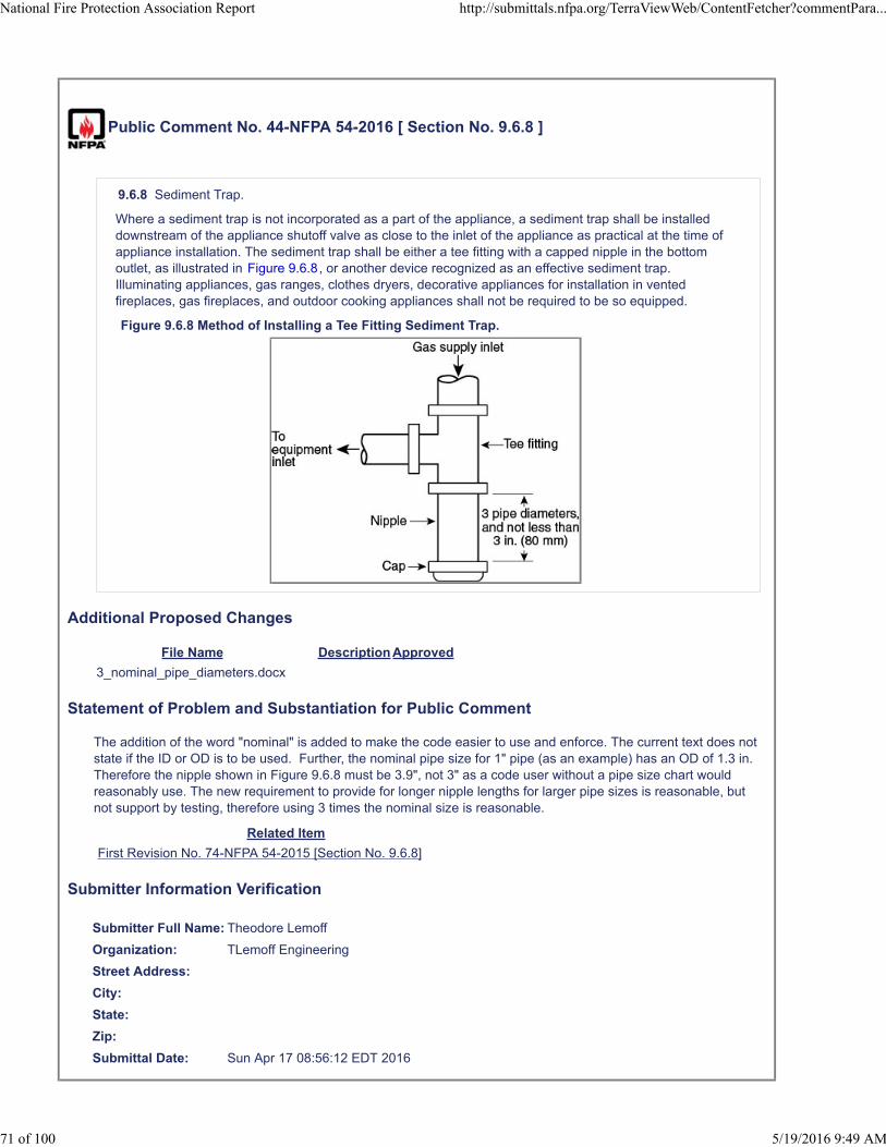
Public Comment No. 44-NFPA 54-2016 [ Section No. 9.6.8 ]
9.6.8 Sediment Trap.
Where a sediment trap is not incorporated as a part of the appliance, a sediment trap shall be installeddownstream of the appliance shutoff valve as close to the inlet of the appliance as practical at the time ofappliance installation. The sediment trap shall be either a tee fitting with a capped nipple in the bottomoutlet, as illustrated in Figure 9.6.8, or another device recognized as an effective sediment trap.Illuminating appliances, gas ranges, clothes dryers, decorative appliances for installation in ventedfireplaces, gas fireplaces, and outdoor cooking appliances shall not be required to be so equipped.
Figure 9.6.8 Method of Installing a Tee Fitting Sediment Trap.
Additional Proposed Changes
File Name Description Approved
3_nominal_pipe_diameters.docx
Statement of Problem and Substantiation for Public Comment
The addition of the word "nominal" is added to make the code easier to use and enforce. The current text does not state if the ID or OD is to be used. Further, the nominal pipe size for 1" pipe (as an example) has an OD of 1.3 in. Therefore the nipple shown in Figure 9.6.8 must be 3.9", not 3" as a code user without a pipe size chart would reasonably use. The new requirement to provide for longer nipple lengths for larger pipe sizes is reasonable, but not support by testing, therefore using 3 times the nominal size is reasonable.
Related Item
First Revision No. 74-NFPA 54-2015 [Section No. 9.6.8]
Submitter Information Verification
Submitter Full Name: Theodore Lemoff
Organization: TLemoff Engineering
Street Address:
City:
State:
Zip:
Submittal Date: Sun Apr 17 08:56:12 EDT 2016
National Fire Protection Association Report http://submittals.nfpa.org/TerraViewWeb/ContentFetcher?commentPara...
71 of 100 5/19/2016 9:49 AM

3 nominal pipe diameters, minimum and not less than 3 in. (80 mm)

Public Comment No. 46-NFPA 54-2016 [ New Section after 10.8 ]
Delete Sections 10.8 and 10.9 and replace with the following new section covering both types of DirectGas-Fired Industrial Air Heaters:
10.8 Direct Gas-Fired Industrial Air Heaters.
10.8.1 Types of Direct Gas-Fired Industrial Air Heaters
10.8.1 .1 Non-Recirculating direct gas-fired industrial air heaters. Non-recirculating direct gas-firedindustrial air heaters shall be listed in accordance with ANSI Z83.4/CSA 3.7, Non-Recirculating DirectGas-Fired Industrial Air Heaters .
10.8. 1.2 Recirculating direct gas-fired industrial air heaters of the recirculating type direct gas-firedindustrial air heaters shall be listed in accordance with ANSI Z83.18, Recirculating Direct Gas-FiredIndustrial Air Heaters .
10.8.2 Prohibited Installations.
10.8.2.1 Non-recirculating direct gas-fired industrial air heaters shall not serve any area containing sleepingquarters.
10.8.2.2 Non-recirculating direct gas-fired industrial air heaters shall not recirculate room air.
10.8.3 Installation. Direct gas-fired industrial air heaters shall be installed in accordance with themanufacturer’s instructions.
10.8.4 Clearance from Combustible Materials. Direct gas-fired industrial air heaters shall be installedwith a clearance from combustible materials of not less than that shown on the rating plate and themanufacturer’s instructions.
10.8.5 Air Supply. All outdoor air to the direct gas-fired industrial air heater shall be ducted directly fromoutdoors. Where outdoor air dampers or closing louvers are used, they shall be verified to be in the openposition prior to main burner operation.
10.8.6 Atmospheric Vents or Gas Reliefs or Bleeds. Direct gas-fired industrial air heaters with valve traincomponents equipped with atmospheric vents, gas reliefs, or bleeds shall have their vent lines, gas reliefs, orbleeds lead to a safe point outdoors. Means shall be employed on these lines to prevent water from enteringand to prevent blockage from insects and foreign matter. An atmospheric vent line shall not be required to beprovided on a valve train component equipped with a listed vent limiter.
10.8.7 Relief Openings. The design of the installation shall include adequate provisions to permit the directgas-fired industrial air heater to operate at its rated airflow without overpressurizing the space served by theheater by taking into account the structure’s designed infiltration rate, properly designed relief openings, oran interlocked powered exhaust system, or a combination of these methods.
10.8.7.1 The structure’s designed infiltration rate and the size of relief opening(s) shall be determined byapproved engineering methods.
10.8.7.2 Louver or counterbalanced gravity damper relief openings shall be permitted. Where motorizeddampers or closable louvers are used, they shall be proved to be in their open position prior to main burneroperation.
10.8.8 Purging. Inlet ducting, when used, shall be purged with at least four air changes prior to an ignitionattempt.
10.8.9 Additional Requirements for Non-Recirculating Direct gas-fired Indust rial Air Heaters
10.8.9.2 Non-recirculating direct gas-fired industrial air heaters shall be permitted to provide fresh airventilation.
10.8.9.3 Non-recirculating direct gas-fired industrial air heaters shall be provided with access for removal ofburners; for replacement of motors, controls, filters, and other working parts; and for adjustment andlubrication of parts requiring maintenance.
10.8.10 Additional Requirements for Recirculating Direct Gas-Fired Industrial Air Heaters
10.8.10.1* Recirculating direct gas-fired industrial air heaters shall not recirculate room air in buildings thatcontain flammable solids, liquids, or gases; explosive materials; or substances that can become toxic when
National Fire Protection Association Report http://submittals.nfpa.org/TerraViewWeb/ContentFetcher?commentPara...
72 of 100 5/19/2016 9:49 AM

exposed to flame or heat.
10.8.10.2 Air to the recirculating direct gas-fired industrial air heater in excess of the minimum ventilation airspecified on the heater’s rating plate shall be taken from the building, ducted directly from outdoors, or acombination of both.
Statement of Problem and Substantiation for Public Comment
Sections 10.8 and 10.9 covering the 2 types of gas-fired industrial air heaters are repetitive, and it is recommended that they be combined to extensive delete duplication. This is believed to be reasonable as the requirements are very similar. No changes have been made to the existing requirements in this comment.
Related Public Comments for This Document
Related Comment Relationship
Public Comment No. 47-NFPA 54-2016 [Section No. 10.9]
Related Item
Public Input No. 75-NFPA 54-2015 [Section No. 3.3.77]
First Revision No. 76-NFPA 54-2015 [Section No. 10.9.3]
Submitter Information Verification
Submitter Full Name: Theodore Lemoff
Organization: TLemoff Engineering
Street Address:
City:
State:
Zip:
Submittal Date: Tue Apr 19 10:40:21 EDT 2016
National Fire Protection Association Report http://submittals.nfpa.org/TerraViewWeb/ContentFetcher?commentPara...
73 of 100 5/19/2016 9:49 AM

Public Comment No. 47-NFPA 54-2016 [ Section No. 10.9 ]
10.9 Recirculating Direct Gas-Fired Industrial Air Heaters.
10.9.1 Application.
Direct gas-fired industrial air heaters of the recirculating type shall be listed in accordance with ANSIZ83.18, Recirculating Direct Gas-Fired Industrial Air Heaters .
10.9.2 Prohibited Installations.
10.9.2.1
Recirculating direct gas-fired industrial air heaters shall not serve any area containing sleeping quarters.
10.9.2.2 *
Recirculating direct gas-fired industrial air heaters shall not recirculate room air in buildings that containflammable solids, liquids, or gases; explosive materials; or substances that can become toxic whenexposed to flame or heat.
10.9.3 Installation.
Recirculating direct gas–fired industrial air heaters shall be installed in accordance with the manufacturer’sinstructions.
10.9.4 Clearance from Combustible Materials.
Recirculating direct gas-fired industrial air heaters shall be installed with a clearance from combustiblematerials of not less than that shown on the rating plate and the manufacturer’s instructions.
10.9.5 Air Supply.
Ventilation air to the recirculating direct gas-fired industrial air heater shall be ducted directly from outdoors.Air to the recirculating direct gas-fired industrial air heater in excess of the minimum ventilation air specifiedon the heater’s rating plate shall be taken from the building, ducted directly from outdoors, or a combinationof both. Where outdoor air dampers or closing louvers are used, they shall be verified to be in the openposition prior to main burner operation.
10.9.6 Atmospheric Vents, Gas Reliefs, or Bleeds.
Recirculating direct gas-fired industrial air heaters with valve train components equipped with atmosphericvents, gas reliefs, or bleeds shall have their vent lines, gas reliefs, or bleeds lead to a safe point outdoors.Means shall be employed on these lines to prevent water from entering and to prevent blockage frominsects and foreign matter. An atmospheric vent line shall not be required to be provided on a valve traincomponent equipped with a listed vent limiter.
10.9.7 Relief Openings.
The design of the installation shall include adequate provisions to permit the recirculating direct gas-firedindustrial air heater to operate at its rated airflow without overpressurizing the space served by the heater,by taking into account the structure’s designed infiltration rate, properly designed relief openings, aninterlocked powered exhaust system, or a combination of these methods.
10.9.7.1
The structure’s designed infiltration rate and the size of relief opening(s) shall be determined by approvedengineering methods.
10.9.7.2
Louver or counterbalanced gravity damper relief openings shall be permitted. Where motorized dampers orclosable louvers are used, they shall be proved to be in their open position prior to main burner operation.
10.9.8 Purging.
Inlet ducting, when used, shall be purged with at least four air changes prior to an ignition attempt.
National Fire Protection Association Report http://submittals.nfpa.org/TerraViewWeb/ContentFetcher?commentPara...
74 of 100 5/19/2016 9:49 AM

Statement of Problem and Substantiation for Public Comment
See Comment on Section 10.8. Sections 10.8 and 10.9 covering the 2 types of gas-fired industrial air heaters are repetitive, and it is recommended that they be combined to extensive delete duplication. This is believed to be reasonable as the requirements are very similar. No changes have been made to the existing requirements in this comment.
Related Public Comments for This Document
Related Comment Relationship
Public Comment No. 46-NFPA 54-2016 [New Section after 10.8]
Related Item
First Revision No. 75-NFPA 54-2015 [Section No. 10.8.3.2]
Submitter Information Verification
Submitter Full Name: Theodore Lemoff
Organization: TLemoff Engineering
Street Address:
City:
State:
Zip:
Submittal Date: Tue Apr 19 10:45:02 EDT 2016
National Fire Protection Association Report http://submittals.nfpa.org/TerraViewWeb/ContentFetcher?commentPara...
75 of 100 5/19/2016 9:49 AM

Public Comment No. 70-NFPA 54-2016 [ Section No. 10.22.1.1 ]
10.22.1.1 Installation in Fireplaces.
Unvented room heaters shall not be installed in factory-built fireplaces except where the factory-builtfireplace is listed for use with unvented room heaters.
Statement of Problem and Substantiation for Public Comment
The new requirement was not supported by technical data that demonstrated that installing an unvented heater in a factory-built fireplace that was not specifically listed for those heaters is a safety issue.
Related Item
First Revision No. 49-NFPA 54-2015 [New Section after 10.22.1]
Submitter Information Verification
Submitter Full Name: James Ranfone
Organization: American Gas Assn
Street Address:
City:
State:
Zip:
Submittal Date: Tue May 10 14:18:16 EDT 2016
National Fire Protection Association Report http://submittals.nfpa.org/TerraViewWeb/ContentFetcher?commentPara...
76 of 100 5/19/2016 9:49 AM
Public Comment No. 71-NFPA 54-2016 [ Section No. 10.22.1.1 ]
10.22.1.1 Installation in Fireplaces.
Unvented room heaters shall not be installed in factory-built fireplaces except where the factory-builtfireplace is listed for use with unvented room heaters.
Statement of Problem and Substantiation for Public Comment
This proposed provision is unnecessary and inconsistent with requirements in the standards applicable to factory built fireplaces (UL127) and unvented room heaters (ANSI Z21.11.2). The issue being addressed in this proposal was first discussed within the ICC code arena in the late 1990's. At that time CSA and Underwriters Laboratories (UL) collaborated on this issue. Industry members representing listed unvented room heaters and factory-built fireplaces were invited to participate. Recognizing that all combinations of these two types of products could not be tested, CSA conducted actual fire-hazard testing on the identified worse-case fireplaces (including dome top models) and the highest temperature (primarily maximum input) unvented gas log sets. CSA did the testing with UL participation. As a result of that evaluation it was determined that the installation of gas log sets in factory built fireplaces does not present a fire hazard.
In response, the applicable standards were changed years ago to accommodate the findings. UL127 gives factory-built fireplace manufacturers the option to list their product either (a) for use with unvented gas log sets or (b) with a warning to not use unvented gas log sets. The second option permits the manufacturer to disallow the application if that is its desire. The related markings and instructions required by the standard indicate this key information to the installer. ANSI Z21.11.2 includes testing for log sets in this application. It is a absolute requirement for certification and listing of the unvented gas log sets. The markings and instructions with the logs et provide clear direction to the installer to check what is indicated on the UL127 factory-built fireplace markings and instructions to see whether or not the installation is permitted.
This situation has been in place for many years and there is no indication that it has not effectively addressed the safe and proper use of gas log sets in factory built fireplaces. The research conducted years ago showed that gas log sets can be used safely in factory built fireplaces. That is the default situation. The option in UL 127 was added to recognize that a manufacturer of factory built fireplaces may choose to not sanction the use of his products with gas log sets. But this is a choice based on personal preference, not a safety-related issue.
Related Item
First Revision No. 49-NFPA 54-2015 [New Section after 10.22.1]
Submitter Information Verification
Submitter Full Name: Frank Stanonik
Organization: Air Conditioning, Heating, and Refrigeration Institute
Street Address:
City:
State:
Zip:
Submittal Date: Fri May 13 10:56:38 EDT 2016
National Fire Protection Association Report http://submittals.nfpa.org/TerraViewWeb/ContentFetcher?commentPara...
77 of 100 5/19/2016 9:49 AM

Public Comment No. 92-NFPA 54-2016 [ Section No. 10.22.1.1 ]
10.22.1.1 Installation in Fireplaces.
Unvented room heaters shall not be installed in factory-built fireplaces except where the factory-builtfireplace is listed for use with unvented room heaters.
Statement of Problem and Substantiation for Public Comment
Currently, UL 127 requires the manufacturer's instructions for all units to include a statement as to whether or not a listed gas log set can be installed in the fireplace. For older factory built fireplaces, such a statement may not have been required. However, we are informed that in the late 1990s, testing was performed at CSA and with the involvement of Underwriters Laboratories to match worst case log sets with worst case factory built fireplaces and determine the critical temperature rises. This testing verified that in all cases, factory built fireplaces were able to accommodate the installation of listed gas log sets.
Therefore, considering this research and the fact that UL 127 now requires a declaration, the proposed text is not justified and should be stricken.
Related Item
Public Input No. 49-NFPA 54-2015 [Section No. 12.6.5.4]
Submitter Information Verification
Submitter Full Name: Bruce Swiecicki
Organization: National Propane Gas Associati
Street Address:
City:
State:
Zip:
Submittal Date: Mon May 16 15:27:17 EDT 2016
National Fire Protection Association Report http://submittals.nfpa.org/TerraViewWeb/ContentFetcher?commentPara...
78 of 100 5/19/2016 9:49 AM
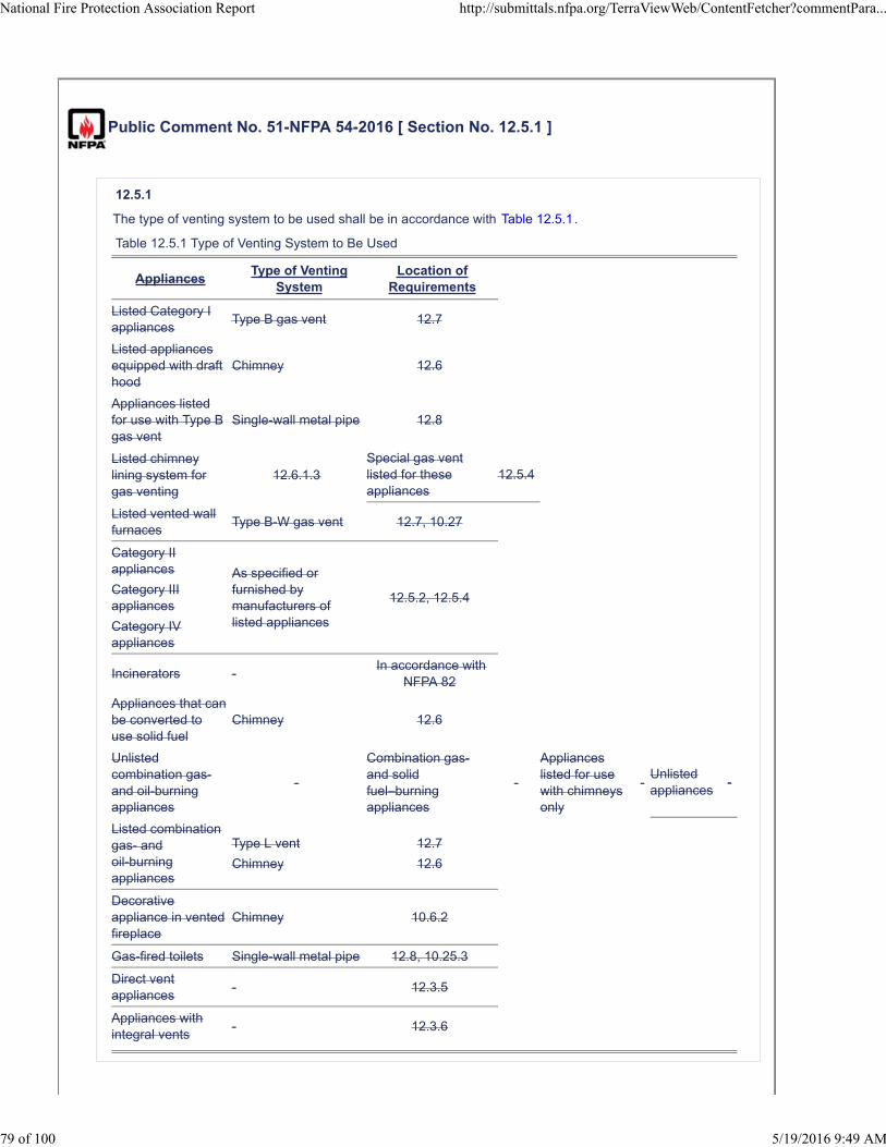
Public Comment No. 51-NFPA 54-2016 [ Section No. 12.5.1 ]
12.5.1
The type of venting system to be used shall be in accordance with Table 12.5.1.
Table 12.5.1 Type of Venting System to Be Used
AppliancesType of Venting
SystemLocation of
Requirements
Listed Category Iappliances
Type B gas vent 12.7
Listed appliancesequipped with drafthood
Chimney 12.6
Appliances listedfor use with Type Bgas vent
Single-wall metal pipe 12.8
Listed chimneylining system forgas venting
12.6.1.3Special gas ventlisted for theseappliances
12.5.4
Listed vented wallfurnaces
Type B-W gas vent 12.7, 10.27
Category IIappliances
Category IIIappliances
Category IVappliances
As specified orfurnished bymanufacturers oflisted appliances
12.5.2, 12.5.4
Incinerators -In accordance with
NFPA 82
Appliances that canbe converted touse solid fuel
Chimney 12.6
Unlistedcombination gas-and oil-burningappliances
-
Combination gas-and solidfuel–burningappliances
-
Applianceslisted for usewith chimneysonly
-Unlistedappliances
-
Listed combinationgas- andoil-burningappliances
Type L vent
Chimney
12.7
12.6
Decorativeappliance in ventedfireplace
Chimney 10.6.2
Gas-fired toilets Single-wall metal pipe 12.8, 10.25.3
Direct ventappliances
- 12.3.5
Appliances withintegral vents
- 12.3.6
National Fire Protection Association Report http://submittals.nfpa.org/TerraViewWeb/ContentFetcher?commentPara...
79 of 100 5/19/2016 9:49 AM

AppliancesType of Venting
System
Location of
Requirements
Listed Category I
appliancesType B gas vent 12.7
Chimney 12.6
Single-wall metal
pipe12.8
Listed chimney
lining system for
gas venting 12.6.1.3
Appliances listed for use
with Type B gas vent
Special gas vent
listed for these
appliances 12.5.4
Listed vented wall
furnacesType B-W gas vent 12.7, 10.27
Category appliances
Category III appliances
Category IV appliances
Incinerators AnyIn accordance with
NFPA 82
Appliances that can be
converted to use solid
fuel
Chimney
Unlisted combination gas-
and oil-burning
appliances
Combination gas- and
solid fuel–burning
appliances
Chimney 12.6
Appliances listed for use
with chimneys only
Unlisted appliances
Listed combination gas
and oil-burning
appliances
Type L vent
Chimney
12.7
12.6
Decorative appliance in
vented fireplace
Chimney 10.6.2
Gas-fired toilets Single-wall metal
pipe12.8, 10.25.3
Table 12.5.1 Type of Venting System to Be Used
As specified or
furnished by
manufacturers of
listed appliances
12.5.2, 12.5.4
Listed appliances
equipped with draft hood

Direct vent appliances
In accorcance with
the manufacturer's
installation
instructions and
12.9.3
12.3.5
Appliances with integral
vents
In accorcance with
the manufacturer's
installation
instructions and
12.9.1 and 12.9.2
12.3.6

Appliances listed for use with Type B gas vent
Incinerators Any
Appliances listed for use with chimneys only
Listed combination gas
and oil-burning
appliances
Type L
vent
Chimne
y
12.7
12.6
Decorative appliance in
vented fireplace
Chimney 10.6.2
Gas-fired toilets
Single-
wall
metal
pipe
12.8, 10.25.3
Direct vent appliances
In
accorca
nce with
the
manufa
cturer's
installati
on
instructi
ons and
12.9.3
12.3.5

Appliances with integral
vents
In
accorca
nce with
the
manufa
cturer's
installati
on
instructi
ons and
12.9.1
and
12.9.2
12.3.6

Additional Proposed Changes
File Name Description Approved
Revised_Table_12-5-1_Comment.xlsx
Statement of Problem and Substantiation for Public Comment
Table 12.5.1 is revised to improve the format and delete the “dashes”. No information is provided to the code user on the meaning of dashes. The types of venting systems or location of requirements replace the dashes. The types of appliances in the first row are separated to more clearly indicate that all 5 types of venting systems can be used.The reference to NFPA 82 in the incinerator row is widened to two columns, as both the type of venting system is specified in NFPA 82.In the row for gas and oil-burning and gas and solid fuel-burning appliances “chimney” is centered vertically to more clearly indicate that chimneys must be used for all 5 types of appliances.The last 2 rows have the type of venting system replacing dashes.These changes return the table to the format used in earlier editions and correct inadvertent format and layout revisions.
Related Item
Committee Input No. 70-NFPA 54-2015 [Section No. 12.5]
Submitter Information Verification
Submitter Full Name: Theodore Lemoff
Organization: TLemoff Engineering
Street Address:
City:
State:
Zip:
Submittal Date: Thu Apr 21 11:19:34 EDT 2016
National Fire Protection Association Report http://submittals.nfpa.org/TerraViewWeb/ContentFetcher?commentPara...
80 of 100 5/19/2016 9:49 AM

Public Comment No. 76-NFPA 54-2016 [ Section No. 12.5.1 ]
12.5.1
The type of venting system to be used shall be in accordance with Table 12.5.1.
Table 12.5.1 Type of Venting System to Be Used
Appliances Type of Venting SystemLocation of
Requirements
Listed Category I appliances Type B gas vent 12.7
Listed appliances equipped with drafthood
Chimney 12.6
Appliances listed for use with Type Bgas vent
Single-wall metal pipe 12.8
Listed chimney lining system for gasventing
12.6.1.3
Special gas vent listed for theseappliances
12.5.4
Listed vented wall furnaces Type B-W gas vent 12.7, 10.27
Category II
appliances
, Category III
appliances
and
Category IV appliances
As specified or furnished by manufacturers of listed appliances
Special gas vent listed for these appliances12.5.2
,
12.5.4
Incinerators - In accordance with NFPA 82
Appliances that can be converted to use solid fuel Chimney 12.6
Unlisted combination gas- and oil-burning appliances -
Combination gas- and solid fuel–burning appliances -
Appliances listed for use with chimneys only -
Unlisted appliances -
Listed combination gas- and oil-burning appliancesType L vent
Chimney
12.7
12.6
Decorative appliance in vented fireplace Chimney 10.6.2
Gas-fired toilets Single-wall metal pipe 12.8, 10.25.3
Direct vent appliances - 12.3.5
Appliances with integral vents - 12.3.6
Statement of Problem and Substantiation for Public Comment
Two methods are appropriate for venting Categories II, III, and IV appliances – (1) As specified or furnished by manufacturers of listed appliances or (2) listed special gas vents. In the current code language, Table 12.5.1 already recognizes the second method by referencing Section 12.5.4. Also, listed special gas vents are already
National Fire Protection Association Report http://submittals.nfpa.org/TerraViewWeb/ContentFetcher?commentPara...
81 of 100 5/19/2016 9:49 AM

recognized in the current code for other types of appliances in Table 12.5.1. Section 12.5.4 already requires special gas vents to be listed. ANSI/UL 1738 is the standard for listing special gas vents.
Related Public Comments for This Document
Related Comment Relationship
Public Comment No. 77-NFPA 54-2016 [Section No. 12.5.4]
Related Item
Public Input No. 82-NFPA 54-2015 [Section No. 12.5.4]
Submitter Information Verification
Submitter Full Name: John Taecker
Organization: UL LLC
Street Address:
City:
State:
Zip:
Submittal Date: Sat May 14 10:28:58 EDT 2016
National Fire Protection Association Report http://submittals.nfpa.org/TerraViewWeb/ContentFetcher?commentPara...
82 of 100 5/19/2016 9:49 AM

Public Comment No. 72-NFPA 54-2016 [ Sections 12.5.2, 12.5.3 ]
Sections 12.5.2, 12.5.3
12.5.2 Plastic Piping.
Where plastic piping is used to vent an appliance, the appliance shall be listed for use with such ventingmaterials and the appliance manufacturer's installation instructions shall identify the specific plastic pipingmaterial. The plastic pipe venting materials shall be labelled in accordance with the product standardsspecified by the appliance manufacturer or shall be listed and labeled in accordance with UL 1738.
12.5.3 Plastic Vent Joints.
Plastic pipe and fittings used to vent appliances shall be installed in accordance with the appliancemanufacturer's and the vent manufacturers installation instructions if available . Where primer is required, itshall be of a contrasting color.
Additional Proposed Changes
File Name Description Approved
NFPA_54_Venting_Public_Comment.docx UL 1738 Proposal Rationale
CI_70_Section_12.5.pdf Original Proposal and ballot comments
Statement of Problem and Substantiation for Public Comment
A proposal to mandate that plastic venting be certified to UL 1738 - Standard for Safety – Venting Systems for Gas-Burning Appliances Categories II, III, and IV was considered by the NFPA committee (see attachment 1 at the end of this document). The proposal failed to obtain the number of positive votes required for acceptance. We have reviewed the negatives and responses and we believe that a compromise would better serve the involved parties and resolve the ballot comments. The compromise would be to amend the proposal to permit plastic venting to meet the appliance standards with an option to meet UL 1738. This would accomplish the following:
1. Maintain the current requirement and highlight that there is an option to use UL 1738 certified products. 2. Stakeholders can decide which standard(s) they want to use for plastic venting for the vent materials listed for use by the Appliance Manufacturer.3. Address the comments related to the conflict created by mandating UL 1738 as the only alternative.
Related Item
Committee Input No. 70-NFPA 54-2015 [Section No. 12.5]
Public Input No. 139-NFPA 54-2015 [Section No. 12.5.3]
Submitter Information Verification
Submitter Full Name: Larry Gill
Organization: Ipex Mgmt Inc
Street Address:
City:
State:
Zip:
Submittal Date: Fri May 13 13:26:15 EDT 2016
National Fire Protection Association Report http://submittals.nfpa.org/TerraViewWeb/ContentFetcher?commentPara...
83 of 100 5/19/2016 9:49 AM

May 12, 2016
Public comment on NFPA 54
From: Larry Gill and Gaetano Altomare – IPEX USA LLC
Background
A proposal to mandate that plastic venting be certified to UL 1738 - Standard for Safety – Venting
Systems for Gas-Burning Appliances Categories II, III, and IV was considered by the NFPA committee
(see attachment 1 at the end of this document). The proposal failed to obtain the number of positive
votes required for acceptance. We have reviewed the negatives and responses and we believe that a
compromise would better serve the involved parties and resolve the ballot comments. The compromise
would be to amend the proposal to permit plastic venting to meet the appliance standards with an
option to meet UL 1738. This would accomplish the following:
1. Maintain the current requirement and highlight that there is an option to use UL 1738 certified
products.
2. Stakeholders can decide which standard(s) they want to use for plastic venting for the vent
materials listed for use by the Appliance Manufacturer.
3. Address the comments related to the conflict created by mandating UL 1738 as the only
alternative.
In addition to this proposed Code change we will undertake to propose revisions to the appliance
standards to recognise UL 1738 as a standard for venting. Note that this code change does not rely on
concurrent changes to the appliance standards. Currently the appliance standards only mandate that a
material (PVC for example) with a specific Heat Deflection Temperature (HDT) be used. The appliance
standards reference certain ASTM and CSA plastics standards but they do not mandate that the vent
product be listed or labeled to these ASTM and CSA standards.
The Proposal
12.5.2 Plastic Piping.
Where plastic piping is used to vent an appliance, the appliance shall be listed for use with such venting
materials and the appliance manufacturer's installation instructions shall identify the specific plastic
piping material. The plastic pipe venting materials shall be labeled in accordance with the product
standards specified by the appliance manufacturer or shall be listed and labeled in accordance with UL
1738.
12.5.3 Plastic Vent Joints.
Plastic pipe and fittings used to vent appliances shall be installed in accordance with the appliance
manufacturers and the vent manufacturers’ installation instructions if available. Where primer is
required, it shall be of a contrasting color.

Rationale
Currently in the United States plastic flue gas venting is required to meet the appliance standards. The
appliance standards mandate that plastic vent materials be tested with the appliance for various
scenarios. The temperature of the plastic vent is measured at defined locations with a requirement that
the temperature cannot exceed the HDT for the plastic in question (PVC, ABS and CPVC). This system of
plastic venting has been in use successfully for many years.
Recently the appliance standards were revised to exclude Cell core PVC and ABS due to concerns with
the thin outside layer deteriorating when assembled. In Canada there were incidents involving ABS
which prompted ULC S636 to be mandated in the B149 gas Code in 2007. Further, in Canada ABS is no
longer permitted as a venting material. ULC S636 has some similarities to UL 1738 but the standards are
different. In the United States it appears that there have been reported appliance venting related
incidents but details are lacking other than for a handful of incidents.
Clearly there have been some venting “issues” and the industry has reacted with changes to the
appliance standards and the Gas Code in Canada. Even if all parties cannot agree that there is a problem
that needs to be corrected we should be able to agree that an alternative to the current offering is a
reasonable step.
There have been ongoing discussions amongst the appliance manufacturers, vent manufacturers and
the NPFA 54 Code regarding the installation of non-metallic venting systems with no resolution. The
purpose of this change is to attempt resolution by maintaining the current requirements while
highlighting the option of using UL 1738. This will allow all parties to be able to specify and install what
they and their customers want. This proposal does not raise any concerns with the existing ASTM and
CSA appliance referenced standards.
This proposal is intended to provide options for manufacturers, users and regulators. If approved it
would permit venting to meet the requirements of the appliance standards (ASTM and CSA referenced
standards for venting), with the option to meet UL 1738.
Attachment 1
CI 70 Section 12.5.pdf

Committee Input No. 70-NFPA 54-2015 [ Section No. 12.5 ]
This was a First Revision that failed ballot.
12.5 Type of Venting System to Be Used.
12.5.1
The type of venting system to be used shall be in accordance with Table 12.5.1.
Table 12.5.1 Type of Venting System to Be Used
Appliances Type of Venting SystemLocation of
Requirements
Listed Category I appliances Type B gas vent 12.7Listed appliances equipped withdraft hood Chimney 12.6
Appliances listed for use with TypeB gas vent Single-wall metal pipe 12.8
Listed chimney lining system for gasventing 12.6.1.3
Special gas vent listed for theseappliances 12.5.4
Listed vented wall furnaces Type B-W gas vent 12.7, 10.27
Category II appliances Category ,III, and IV appliancesCategory IV appliances
As specified or furnished bymanufacturers of listed appliances - 12.5.2,
12.5.4
Incinerators - In accordance withNFPA 82
Appliances that can be converted touse solid fuel Chimney 12.6
Unlisted combination gas- andoil-burning appliances -
Combination gas- and solidfuel–burning appliances -
Appliances listed for use withchimneys only -
Unlisted appliances -
Listed combination gas- andoil-burning appliances
Type L ventChimney
12.712.6
Decorative appliance in ventedfireplace Chimney 10.6.2
Gas-fired toilets Single-wall metal pipe 12.8, 10.25.3
Direct vent appliances - 12.3.5, 12.5.2
Appliances with integral vents - 12.3.6
National Fire Protection Association Report http://submittals.nfpa.org/TerraViewWeb/FormLaunch?id=/TerraView/C...
1 of 4 4/1/2016 2:40 PM

12.5.2 Plastic Piping.
Where plastic piping is used to vent an appliance, the
(1) Such piping shall be listed and labeled in accordance with UL 1738.
(2) The piping shall be installed in accordance with the piping manufacturer's instructions and the conditions ofits listing.
(3) The appliance shall be listed for use with such venting materials and the .
(4) The appliance manufacturer's installation instructions shall identify the specific type of plastic pipingmaterial to be used .
12.5.3 Plastic Vent Solvent Cemented Joints.
Plastic pipe and fittings used to vent appliances shall be installed in accordance with the appliancemanufacturer's installation instructions. Where Where a primer is required , it for solvent cemented joints, theprimer shall be of a contrasting color.
12.5.4 Special Gas Vents.
Special gas vents shall be listed and labeled in accordance with UL 1738 and installed in accordance with thespecial gas vent manufacturer's installation instructions.
Submitter Information Verification
Submitter Full Name: Laura MontvilleOrganization: [ Not Specified ]Street Address:
City:
State:
Zip:
Submittal Date: Wed Oct 14 16:52:13 EDT 2015
Committee Statement and Meeting Notes
CommitteeStatement:
The code is revised to require all venting products to be listed. The thorough evaluation required byUL 1738 will ensure that the products used as venting materials are intended by the manufacturersfor that purpose.
ResponseMessage:
Committee Notes:
Date Submitted By
Oct 30,2015
Laura Montville Revisions to "category II, III and IV" row, and to "direct-vent appliances" row. Revisions to sections underneath table as well.
Public Input No. 82-NFPA 54-2015 [Section No. 12.5.4]
Public Input No. 135-NFPA 54-2015 [Section No. 12.5.2]
Ballot Results
This item has failed ballot
26 Eligible Voters1 Not Returned
10 Negative with Comments15 Affirmative All
0 Affirmative with Comments
National Fire Protection Association Report http://submittals.nfpa.org/TerraViewWeb/FormLaunch?id=/TerraView/C...
2 of 4 4/1/2016 2:40 PM

0 Abstention
Not Returned
Fossa, Alberto Jose
Negative with Comment
Berning, David
The revision would require all plastic materials used to vent Category II, III, and IV appliances to meet UL 1738. Thischange would place the code in direct conflict with several ANSI safety standards for gas appliances, such as forwater heaters (ANSI Z21.10.1 and Z21.10.3), boilers (ANSI Z21.13), and central furnaces (ANSI Z21.47). Thesestandards for years have allowed for the use of PVC and CPVC materials for use in venting condensing gasappliances, when certain testing and performance conditions are met. This ensures that the safe performance of suchmaterials is met when certifying a specific appliance design for use with plastic materials. In addition, the water heaterand boiler standards have updated their coverage to prohibit the use of cellular core PVC and CPVC. This codeproposal would not only require manufacturers of certified appliances to search for UL 1738 listed plastic ventingsystems, but it would place in doubt those plastic venting systems that have been certified as part of a listed appliancewith proven safe performance in the field for many years. It is not known if any PVC or CPVC plastic venting systemsexist on the market that are listed to UL 1738. Testing a plastic venting system separate from the appliance does notensure that the vent system will be appropriate for a specific appliance. The UL 1738 standard makes assumptionsabout the volume and flow of flue gas for the test that in some cases are lower than the actual appliance wouldproduce. The amount of volume and velocity of flue gas will impact the vent pipe wall temperatures that the ventstandard does not replicate for a specific appliance design. There have been efforts made in the past to correlate thevent standard performance test to that of the appliance standard tests for plastic venting systems but this work has notresulted in adequate coverage for the venting standard. Until this is demonstrated and proven to be at least equal tothe appliance standards’ coverage it would be premature to require such a change to the NFGC.
Coates, Sharon E.
The proposal would require a retrofit of all venting systems currently in use and compliance with codes as installedand this proposal would create an unnecessary hardship to retro-fit all systems and maybe not be the safest solution. Ifeel sufficient evidence to require this change was not present.
Corcoran, Shannon M.
The revision would require all plastic piping used to vent Category II, III, and IV appliances to meet the UL 1738. PVCventing materials are currently permitted by the NFGC and the applicable appliance standards. The appliance is testedand certified with the venting systems. The proposed revision to require all plastic venting systems to be listed to UL1783 would create a conflict between the code and appliance standards and manufacturer’s instructions. The publicinput did not provide evidence that a widespread safety issue exists. Nor was any evidence provided that documents adeficiency in the ANSI appliance standards, which require the plastic pipe chosen by the appliance manufacture betested and listed for use with that appliance.
Davis, Gerald G.
This revision would cause a conflict with the current appliance listing for condensing furnaces. The appliance listingallows PVC piping to be used to vent the equipment.
Deegan, Mike
Specifically reviewing the proposal requirement that the use of PVC for venting of category II, III and IV appliances belisted to the UL 1738 standard. Currently the manufacturers of these condensing appliances allow the use of PVC forthe venting of these appliances. This requirement would conflict the manufacturer's design and installation instructions.Additionally no substantiation has been provided that a deficiency exists in the current ANSI standards which requirethe plastic pipe chosen by the appliance manufacture be tested and listed for use with that appliance.
Gorham, Mike
The public input did not establish that any significant safety problem exists. Appliance manufacturers haverecommended non-listed PVC for years and are apparently content to continue to do so. This is a non-problem.
Lemoff, Theodore C.
1. The committee statement that the revision will require all venting products to be listed is not correct. Single WallMetal Pipe is not required to be listed. 2. The format of Table 12.5.1 is changed by deleting "As specified or furnished
National Fire Protection Association Report http://submittals.nfpa.org/TerraViewWeb/FormLaunch?id=/TerraView/C...
3 of 4 4/1/2016 2:40 PM

by manufacturers of listed appliances" with no replacement. A statement should be provided to guide the user, ratherthan have this table serve as an index. 3. No substantiation is provided by the committee to support the newrequirement that plastic gas vents be listed. These product have been in use for at least 20 years. If failures haveoccurred they should have been reported to the committee. In PI 135 the substantiation points to the advantages oflisting plastic venting products to UL 1738, but does not provide any reason that the existing products are notadequate, rather it states that the testing in UL 1738 is more thorough than the current ASTM standards. If listing ofplastic vent products is to be made mandatory, it should be based on technical substantiation that unlisted productsare not working, not that one standard is better than another.
Osterhaus, James T.
Agree with the comments made by those voting in the initial ballot against the proposed revision.
Papageorge, Andrea Lanier
The proposed amendments would require that plastic pipe meet UL 1738 when used to vent category II, III, and IVappliances. PVC, which is currently permitted for use by manufacturers for venting of condensing appliances, is notlisted by UL 1738. There was not sufficient evidence presented to require this change.
Swim, Peter C.
The proposed revision would create a conflict between the code and appliance standards and manufacturer’sinstructions. The public input did not indicate that a safety issue exists.
Affirmative All
Aguilar, Hugo
Antonov, Dmitry
Brania, Jonathan
Brewer, James P.
Crane, Thomas R.
Edgar, Glen A.
Feehan, Pennie L.
Gress, Gregg A.
Hagensen, Steen
Himes, Patricio J.
Holmes, Peter T.
Kulik, Marek
Mortimer, Frank J.
Ribbs, Phillip H.
Switzer, Jr., Franklin R.
Editorial Comment
Click here
National Fire Protection Association Report http://submittals.nfpa.org/TerraViewWeb/FormLaunch?id=/TerraView/C...
4 of 4 4/1/2016 2:40 PM

Public Comment No. 77-NFPA 54-2016 [ Section No. 12.5.4 ]
12.5.4 Special Gas Vents.
Special gas vents shall be listed and labeled in accordance with ANSI/UL 1738, Venting Systems forGas-Burning Appliances, Categories II, III, and IV , and installed in accordance with the special gas ventmanufacturer's installation instructions.
Statement of Problem and Substantiation for Public Comment
Two methods are appropriate for venting Categories II, III, and IV appliances – (1) As specified or furnished by manufacturers of listed appliances or (2) listed special gas vents. In the current code language, Table 12.5.1 already recognizes the second method by referencing Section 12.5.4. Also, listed special gas vents are already recognized in the current code for other types of appliances in Table 12.5.1. Section 12.5.4 already requires special gas vents to be listed. ANSI/UL 1738 is the standard for listing special gas vents.
Related Public Comments for This Document
Related Comment Relationship
Public Comment No. 76-NFPA 54-2016 [Section No. 12.5.1]
Related Item
Public Input No. 82-NFPA 54-2015 [Section No. 12.5.4]
Submitter Information Verification
Submitter Full Name: John Taecker
Organization: UL LLC
Street Address:
City:
State:
Zip:
Submittal Date: Sat May 14 10:33:03 EDT 2016
National Fire Protection Association Report http://submittals.nfpa.org/TerraViewWeb/ContentFetcher?commentPara...
84 of 100 5/19/2016 9:49 AM

Public Comment No. 79-NFPA 54-2016 [ Section No. 12.6.1.3 ]
12.6.1.3 *
Masonry chimneys shall be built and installed in accordance with NFPA 211 and lined with approved oneof the following methods:
1. Approved clay flue lining, a listed chimney lining system, or other
2. A chimney lining system listed and labeled in accordance with ANSI/UL1777, Chimney Liners , or
3. Other approved material that resists corrosion, erosion, softening, or cracking from vent gases attemperatures up to 1800°F (982°C).
Exception: Masonry chimney flues lined with a chimney lining system specifically listed for use with listedappliances with draft hoods, Category I appliances, and other appliances listed for use with Type B ventsshall be permitted. The liner shall be installed in accordance with the liner manufacturer’s installationinstructions. A permanent identifying label shall be attached at the point where the connection is to bemade to the liner. The label shall read “This chimney liner is for appliances that burn gas only. Do notconnect to solid or liquid fuel–burning appliances or incinerators.”
Statement of Problem and Substantiation for Public Comment
Listed chimney lining systems are one of three methods already considered in the current code language to be acceptable for lining a masonry chimney. Reformatting will clarify there is are three different options. The standard used for listing chimney liners is ANSI/UL 1777.
Related Item
Public Input No. 85-NFPA 54-2015 [Section No. 12.6.1.3]
Submitter Information Verification
Submitter Full Name: John Taecker
Organization: UL LLC
Street Address:
City:
State:
Zip:
Submittal Date: Sat May 14 10:46:51 EDT 2016
National Fire Protection Association Report http://submittals.nfpa.org/TerraViewWeb/ContentFetcher?commentPara...
85 of 100 5/19/2016 9:49 AM

Public Comment No. 75-NFPA 54-2016 [ Section No. A.5.6.6.4 ]
A.5.6.6.4
Joint sealing compounds are used in tapered pipe thread joints to provide lubrication to the joint as it istightened so that less tightening torque is “used up” to overcome friction and also to provide a seal of thesmall leak paths that would otherwise remain in a metal-to-metal threaded joint.
Commonly used joint sealing compounds include pipe dope and polytetrafluoroethylene tape, also known
as PTFE or Teflon® tape. Some pipe dopes also contain PTFE. Joint sealing compounds should be appliedso that no sealing compound finds its way into the interior of a completed joint.
Pipe dope application should be made only to the male pipe thread of the joint and should coat all of thethreads commencing one thread back from the end of the threaded pipe.
PTFE tape application should be made by wrapping the tape tightly around the male thread in a clockwisedirection when viewed from the end of the pipe to which the tape is being applied. Tape application shouldwrap all of the threads commencing one thread back from the end of the threaded pipe.
One method to use for sealing is pipe joint sealing compounds listed in accordance with UL 1356, Outlineof Investigation of Pipe Joint Sealing Compounds, which a re suitable for use in joining threaded metalpipe connections in devices handling fluids to assist in rendering joints tight against leakage, when thecompound is identified for use with natural gas.
One method to use for sealing is pipe tape listed in accordance with UL 1321, Outline of Investigation forPolytetrafluoroethylene Plastic Seal Materials, which are intended for application in accordance with themanufacturer's instructions to male threads of metal pipe in devices handling fluids to assist in renderingjoints tight against leakage.
Statement of Problem and Substantiation for Public Comment
The proposal does not require the use of only listed pipe sealing materials. This proposal is simply recognizing that pipe sealing materials that are listed to UL 1321 or UL 1356 are considered suitable for rendering pipe joints tight against leakage. The proposal has been revised to clarify there are other methods. The purpose of Annex A is to provide explanatory material for informational purpose only. This proposal assists the user of NFPA 54 to identify those listed pipe sealing joint compounds and tapes that are considered as suitable for installation in accordance with NFPA 54.
Related Public Comments for This Document
Related Comment Relationship
Public Comment No. 78-NFPA 54-2016 [Section No. K.2.5]
Related Item
Public Input No. 99-NFPA 54-2015 [Section No. A.5.6.7.4]
Public Input No. 79-NFPA 54-2015 [Section No. K.2.5]
Submitter Information Verification
Submitter Full Name: John Taecker
Organization: UL LLC
Street Address:
City:
State:
Zip:
Submittal Date: Sat May 14 10:18:34 EDT 2016
National Fire Protection Association Report http://submittals.nfpa.org/TerraViewWeb/ContentFetcher?commentPara...
86 of 100 5/19/2016 9:49 AM

Public Comment No. 83-NFPA 54-2016 [ New Section after A.7.12.2 ]
Arcing to/from CSST to metal components, grounded metal parts or electrical conductors canoccur under lightning strike conditions near a
structure. Spacing, in addition to bonding, further minimizes development of arcs. Arcing is morelikely to occur if CSST is in contact with, or close proximity
to, metal parts including structural components, other pipe/duct systems, electrical serviceconductors and data conductors. Spacing CSST from metal
structural components, other piping systems (such as water piping, HVAC ducting, electricalequipment, etc.) and electrical conductors minimizes the
possibility of the development of an arc.
Statement of Problem and Substantiation for Public Comment
Addition of this section provides informational detail on spacing of CSST from metal parts for arc avoidance.
Spacing of CSST from metallic objects is recommended by manufacturers and local codes to prevent electrical arcing to CSST from lightning strikes and/or otherelectrical transients. No enforceable/inspectable language exists to consistently articulate this requirement. This input in annex provide additional information withregard to a proposed normative input, PI# 110 and Comment #81.
Adding spacing to CSST installations is justified by empirical observations, test results, physics of arc development and precedent set by some local codes as well asmanufacturer instructions.
Forensic review of CSST puncture as a consequence of near-strike lightning reveals that in many cases an arc develops to or from a metallic component in closeproximity, despite the presence of direct bonding of the CSST to ground electrode system, as required by NFPA 54 and many manufacturers.Review of recent reports and studies, notably the GTI report on the matter, (Validation of Installation Methods for CSST Gas Piping to Mitigate Indirect LightningRelated Damage, September 5, 2013 available on nfpa.org) shows that arcs can develop despite the presence of bonding. Depending on certain variables includingthe length of the bonding conductor and magnitude of the lightning event, arcs may or may not cause damage. Spacing minimizes the possibility of arcing thus furtherminimizing the possibility of damage to the CSST.
While the insulating coating (intended to enhance safety to defeat lightning-related arcing) on the CSST for most manufacturers has a dielectric strength ofapproximately 60 kilovolts, on average, it is not sufficient to guard against the voltages that could be developed in a near-strike lightning event. Addition of the 6-inchspacing provides an additional 450 kilovolt isolation, approximately. In fact, some recent publications suggest that the insulating coating is not effective in minimizingarcing and the actual dielectric strength of the CSST as installed is significantly lower than 60 kilovolts. (Goodson, Icove, ISFI 2014, accessed at:http://goodsonengineering.com/wp-content/uploads/Electrical-Characterization-of-CSST.pdf) Adding the spacing enhances protection by defeating any dielectricstrength reductions imposed by bends in the CSST, damage or irregularity in the coating, dirt on the coating, etc.
As a precedent, some local codes have adopted spacing as a requirement. The most common language used in these codes say to “maintain as much separation asreasonably possible from other electrically conductive systems in the building.” Sample codes were provided with PI #111.
National Fire Protection Association Report http://submittals.nfpa.org/TerraViewWeb/ContentFetcher?commentPara...
87 of 100 5/19/2016 9:49 AM

Related Public Comments for This Document
Related Comment Relationship
Public Comment No. 81-NFPA 54-2016 [New Section after 7.12.2]
Related Item
Public Input No. 111-NFPA 54-2015 [New Section after A.7.13.3]
Submitter Information Verification
Submitter FullName:
John Tobias
Organization: US Department of the Army
Affilliation:Submitter is Chairperson of the NFPA Technical Committee for theInstallation of Lightning Protection Systems (NFPA 780)
Street Address:
City:
State:
Zip:
Submittal Date: Mon May 16 10:14:40 EDT 2016
National Fire Protection Association Report http://submittals.nfpa.org/TerraViewWeb/ContentFetcher?commentPara...
88 of 100 5/19/2016 9:49 AM

Public Comment No. 96-NFPA 54-2016 [ Section No. A.7.12.2 ]
A.7.12.2
The required bonding connection may be made from the piping to the electrical service equipmentenclosure, to the grounded conductor at the electrical service, to the grounding electrode conductor (whereof sufficient size), or directly to the grounding electrode. The bond may also be made to a lightningprotection system grounding electrode (but not to down conductors) if the resulting length of the bondingconductor is shorter. Lightning protection grounding systems are bonded to the electrical service groundingelectrodes, in accordance with NFPA 780, using a method to minimize impedance between the systems.
Listed clamps are manufactured to facilitate attachment of the bonding conductor to either a segment ofrigid pipe or to a CSST-copper alloy fitting. Clamps should be installed to remain accessible when buildingconstruction is complete.
The maximum length of the bonding connection was established based on studies conducted by the GasTechnology Institute in Project Number 21323, Validation of Installation Methods for CSST Gas Piping toMitigate Indirect Lightning Related Damage. The shortest practical length should always be used. Stateand local laws can limit who can attach the bonding connection to the building grounding system.
The size of the bonding conductor, a 6 AWG copper wire, is a minimum size, and larger wire can be used.The requirement also permits conductors of different materials (of equivalent size) and both single wire andmulti-strand.
Statement of Problem and Substantiation for Public Comment
The deleted text was incorporated into A.7.12.2.3 by Public Comment No. 95.
Related Public Comments for This Document
Related Comment Relationship
Public Comment No. 95-NFPA 54-2016 [Section No. A.7.12.2.3]
Related Item
Public Input No. 163-NFPA 54-2015 [New Section after A.7.13.2]
Submitter Information Verification
Submitter FullName:
Mitchell Guthrie
Organization: Engineering Consultant
Affilliation:Grounding and Bonding Task Group Chair, NFPA Committee onLightning Protection (780)
Street Address:
City:
State:
Zip:
Submittal Date: Mon May 16 21:14:34 EDT 2016
National Fire Protection Association Report http://submittals.nfpa.org/TerraViewWeb/ContentFetcher?commentPara...
89 of 100 5/19/2016 9:49 AM

Public Comment No. 95-NFPA 54-2016 [ Section No. A.7.12.2.3 ]
A.7.12.2.3
If the bonding jumper required would be longer than 75 ft, an additional grounding electrode can beinstalled to allow a bonding jumper that is 75 ft or less. The maximum length of the bonding connection wasestablished based on studies conducted by the Gas Technology Institute in Project Number 21323 report,"Validation of Installation Methods for CSST Gas Piping to Mitigate Indirect Lightning Releated Damage." Simulations provided in the GTI report show the benefit of providing grounding of incoming servicesat each service entry. The simulations also calculate acceptable bonding cable lengths for additionalbonds involving CSST installation scenarios. The simulations confirm the shorter the bonding cable themore effective the bond. Efforts should be made to keep the bonding conductors as short as reasonable. Bonding distances of 25 feet or less are preferred. The installation of additional bonds and groundingelectrodes are acceptable as long as these additional grounding electrodes are interconnected with eitherlightning protection system grounding electrodes (where provided) or electrical service groundingelectrodes.
Statement of Problem and Substantiation for Public Comment
The proposed revision consolidates the annex discussion on bonding conductor length to the clause in which it is discussed in the normative section (7.12.2.3). The proposed revision incorporates the intent of PI-163 and PI-165, maintains the reference to the GTI report, makes it clear that the simulations in the GTI report all incorporate an current division at all service entry points, and maintains the existing recommendation that bonding conductors should be kept as short as practicable.
Related Public Comments for This Document
Related Comment Relationship
Public Comment No. 93-NFPA 54-2016 [Section No. 7.12.2.3]
Public Comment No. 96-NFPA 54-2016 [Section No. A.7.12.2]
Related Item
Public Input No. 163-NFPA 54-2015 [New Section after A.7.13.2]
Public Input No. 165-NFPA 54-2015 [New Section after A.7.13.2]
Submitter Information Verification
Submitter FullName:
Mitchell Guthrie
Organization: Engineering Consultant
Affilliation:Grounding and Bonding Task Group Chair, NFPA Committee onLightning Protection (780)
Street Address:
City:
State:
Zip:
Submittal Date: Mon May 16 20:46:00 EDT 2016
National Fire Protection Association Report http://submittals.nfpa.org/TerraViewWeb/ContentFetcher?commentPara...
90 of 100 5/19/2016 9:49 AM

Public Comment No. 50-NFPA 54-2016 [ Section No. C.3 ]
C.3 Leak Check Not Using a Meter.
This test can be done using one of the following methods:
(1) For Any Gas System.
(a) To an appropriate checkpoint, attach a manometer or pressure gauge between the inlet to thepiping system and the first regulator in the piping system, momentarily turn on the gas supply,and observe the gauging device for pressure drop with the gas supply shut off. No discernibledrop in pressure should occur during a period of 3 minutes.
(b) Attach an in-line flow meter between the meter outlet and piping system inlet prior to the firstregulator in the piping system. Slowly turn on the gas supply and observe the metering device. Ifflow does not drop to zero, leakage is indicated.
(2) For Gas Systems Using Undiluted LP-Gas System Preparation for Propane. A leak check performedon an LP-Gas system being placed back in service can be performed by using one of the followingmethods:
(3) Insert a pressure gauge between the container gas shutoff valve and the first-stage regulatoror integral two-stage regulator in the system, admitting full container pressure to the system andthen closing the container shutoff valve. Enough gas should then be released from the system tolower the pressure gauge reading by 10 psi (69 kPa). The system should then be allowed tostand for 3 minutes without showing an increase or a decrease in the pressure gauge reading.
(4) Insert a gauge/regulator test assembly between the container gas shutoff valve and first-stageregulator or integral two-stage regulator in the system. If a gauge/regulator test assembly with aninches water column gauge is inserted, follow the test requirements in C.3(2)(c) ; if agauge/regulator test assembly with a 30 psi gauge is inserted, follow the test requirements inC.3(2)(d) .
(5) For systems with an integral two-stage, one or more second-stage, or one or more line
pressure regulators serving appliances that receive gas at pressures of 1 ⁄ 2 psi (3.5 kPa) orless, insert a water manometer or inches water column gauge into the system downstream ofthe final stage regulator, pressurizing the system with either fuel gas or air to a test pressure of 9
in. w.c. ± 1 ⁄ 2 in. w.c. (2.2 kPa ± 0.1 kPa), and observing the device for a pressure change. Iffuel gas is used as a pressure source, it is necessary to pressurize the system to full operatingpressure, close the container service valve, and then release enough gas from the systemthrough a range burner valve or other suitable means to drop the system pressure to 9 in. w.c. ±1 ⁄ 2 in. w.c. (2.2 kPa ± 0.1 kPa). This ensures that all regulators in the system upstream of thetest point are unlocked and that a leak anywhere in the system is communicated to the gaugingdevice. The gauging device should indicate no loss or gain of pressure for a period of 3 minutes.
(6) When testing a system that has a first-stage regulator, or an integral two-stage regulator, inserta 30 psi (207 kPa) pressure gauge on the downstream side of the first-stage regulator or at theintermediate pressure tap of an integral two-stage regulator, admitting normal operating pressureto the system and then closing the container valve. Enough gas should be released from thesystem to lower the pressure gauge reading by a minimum of 2 psi (13.8 kPa) so that thefirst-stage regulator is unlocked. The system should be allowed to stand for 3 minutes withoutshowing an increase or a decrease in pressure gauge reading.
(7) Insert a gauge/regulator test assembly on the downstream side of the first stage regulator or atthe intermediate pressure tap of an integral two stage regulator. If a gauge/regulator testassembly with an inches water column gauge is inserted, follow the test requirements inC.3(2)(c) ; if a gauge/regulator test assembly with a 30 psi gauge is inserted, follow the testrequirements in C.3(2)(d) .
National Fire Protection Association Report http://submittals.nfpa.org/TerraViewWeb/ContentFetcher?commentPara...
91 of 100 5/19/2016 9:49 AM

Statement of Problem and Substantiation for Public Comment
Editorial revision for consistency.
Related Item
First Revision No. 79-NFPA 54-2015 [Section No. C.3]
Submitter Information Verification
Submitter Full Name: Theodore Lemoff
Organization: TLemoff Engineering
Street Address:
City:
State:
Zip:
Submittal Date: Tue Apr 19 12:00:25 EDT 2016
National Fire Protection Association Report http://submittals.nfpa.org/TerraViewWeb/ContentFetcher?commentPara...
92 of 100 5/19/2016 9:49 AM

Public Comment No. 52-NFPA 54-2016 [ Chapter K ]
Annex K Informational References
K.1 Referenced Publications.
The documents or portions thereof listed in this annex are referenced within the informational sections ofthis code and are not part of the requirements of this document unless also listed in Chapter 2 for otherreasons.
K.1.1 NFPA Publications.
National Fire Protection Association, 1 Batterymarch Park, Quincy, MA 02169-7471.
NFPA 56, Standard for Fire and Explosion Prevention During Cleaning and Purging of Flammable GasPiping Systems, 2017 edition.
NFPA 58, Liquefied Petroleum Gas Code, 2017 edition.
NFPA 68, Standard on Explosion Protection by Deflagration Venting, 2013 edition.
NFPA 90A, Standard for the Installation of Air-Conditioning and Ventilating Systems, 2018 edition.
NFPA 90B, Standard for the Installation of Warm Air Heating and Air-Conditioning Systems, 2018 edition.
NFPA 96, Standard for Ventilation Control and Fire Protection of Commercial Cooking Operations, 2017edition.
NFPA 780, Standard for the Installation of Lightning Protection Systems, 2017 edition.
National Fuel Gas Code Handbook, 2018 edition.
K.1.2 Other Publications.
K.1.2.1 API Publications.
American Petroleum Institute, 1220 L Street, N.W., Washington, DC 20005-4070.
API STD 1104, Welding Pipelines and Related Facilities, 2013.
K.1.2.2 ASHRAE Publications.
American Society of Heating, Refrigerating and Air Conditioning Engineers, Inc., 1791 Tullie Circle, N.E.,Atlanta, GA 30329-2305, (404) 636-8400, www.ashrae.org.
ASHRAE Handbook — Fundamentals, 2013.
ASHRAE Handbook — HVAC Systems and Equipment, 2012.
K.1.2.3 ASME Publications.
American Society of Mechanical Engineers, Two Park Avenue, New York, NY 10016-5990, (800) 843-2763,www.asme.org.
Boiler and Pressure Vessel Code, Section IX and Section IV, 2015.
ANSI/ASME B36.10M, Welded and Seamless Wrought Steel Pipe, 2015.
National Fire Protection Association Report http://submittals.nfpa.org/TerraViewWeb/ContentFetcher?commentPara...
93 of 100 5/19/2016 9:49 AM

K.1.2.4 ASTM Publications.
ASTM International, 100 Barr Harbor Drive, P.O. Box C700, West Conshohocken, PA 19428-2959, (610)833-9585, www.astm.org.
ASTM A53/A53M , Standard Specification for Pipe, Steel, Black and Hot-Dipped, Zinc-Coated, Welded andSeamless, 2012.
ASTM A106/A106M , Standard Specification for Seamless Carbon Steel Pipe for High-TemperatureService, 2014 2015 .
ASTM A254/A254M , Standard Specification for Copper-Brazed Steel Tubing, 2012.
ASTM B88, Standard Specification for Seamless Copper Water Tube, 2014.
ASTM B210, Standard Specification for Aluminum and Aluminum-Alloy Drawn Seamless Tubes Tube ,2012.
ASTM B241/B241M , Standard Specification for Aluminum and Aluminum-Alloy Seamless Pipe andSeamless Extruded Tube, 2012 2016 .
ASTM B280, Standard Specification for Seamless Copper Tube for Air-Conditioning and Refrigeration FieldService, 2013 2016 .
ASTM D2385, Test Method for Hydrogen Sulfide and Mercaptan Sulfur in Natural Gas (Cadmium Sulfate —Iodometric Titration Method), 1981 (Reaffirmed 1990) (withdrawn 1995).
ASTM D2420, Method of Test for Hydrogen Sulfide in Liquefied Petroleum (LP) Gases (Lead AcetateMethod), 2013.
ASTM D2513, Standard Specification for Polyethylene (PE) Gas Pressure Pipe, Tubing, and Fittings, 2014.
ASTM D2513, Standard Specification for Thermoplastic Gas Pressure Pipe, Tubing, and Fittings ,2009.ASTM F1973, Standard Specification for Factory Assembled Anodeless Risers and Transition Fittingsin Polyethylene (PE) and Polyamide 11 (PA11) and Polyamide 12 (PA12) Fuel Gas Distribution Systems,2013.
ASTM F2509, Standard Specification for Field-Assembled Anodeless Riser Kits for Use on OutsideDiameter Controlled Polyethylene Gas Distribution Pipe and Tubing, 2012 2015 .
K.1.2.5 AWS Publications.
American Welding Society, 8669 NW 36 Street, #130, Miami, FL 33166-6672, (800) 443-9353,www.aws.org.
AWS B2.1/B2.1M , Specification for Welding Procedure and Performance Qualification, 2014, Amendment1, 2015 .
AWS B2.2/B2.2M , Specification for Brazing Procedure and Performance Qualification, 2010.
K.1.2.6 CSA Group Publications.
CSA Group, 8501 East Pleasant Valley Road, Cleveland, OH 44131-5575, (216) 524-4990,www.csagroup.org.
ANSI LC 1/CSA 6.26, Fuel Gas Piping Systems Using Corrugated Stainless Steel Tubing (CSST), 2014.
ANSI LC 4, Press-Connect Metallic Fittings for Use in Fuel Gas Distribution Systems, 2012.
ANSI Z21.50/CSA 2.22, Vented Gas Fireplaces, 2014.
ANSI Z21.60/CSA 2.26, Decorative Gas Appliances for Installation in Solid-Fuel Burning Fireplaces, 2012.
K.1.2.7 NACE Publications.
NACE International, 15835 Park Ten Place, Houston, TX 77084-4906, www.nace.org.
NACE SP 0169 SP0169 , Control of External Corrosion on Underground or Submerged Metallic PipingSystems, 2013.
K.1.2.8 UL Publications.
Underwriters Laboratories Inc., 333 Pfingsten Road, Northbrook, IL 60062-2096, www.ul.com.
ANSI/UL 651, Schedule 40 and 80 Rigid PVC Conduit and Fittings, 2011, reapproved 2014.
National Fire Protection Association Report http://submittals.nfpa.org/TerraViewWeb/ContentFetcher?commentPara...
94 of 100 5/19/2016 9:49 AM

K.1.2.9 U.S. Government Publications.
U.S. Government Publishing Office, 732 North Capitol Street, NW, Washington, DC 20402 20401-0001 .
Responding to Residential Carbon Monoxide Incidents, Guidelines for Fire and Other EmergencyResponse Personnel, U.S. Consumer Product Safety Commission, July 23, 2002.
K.1.2.10 Other Publications.
Piping Handbook, 2000, New York: McGraw-Hill Book Company.
Project Number 21323, Validation of Installation Methods for CSST Gas Piping to Mitigate Indirect LightningRelated Damage, Gas Technology Institute 2015.
K.2 Informational References.
The following documents or portions thereof are listed here as informational resources only. They are not apart of the requirements of this document.
K.2.1 NFPA Publications.
National Fire Protection Association, 1 Batterymarch Park, Quincy, MA 02169-7471.
NFPA 30, Flammable and Combustible Liquids Code, 2018 edition.
NFPA 59, Utility LP-Gas Plant Code, 2018 edition.
NFPA 61, Standard for the Prevention of Fires and Dust Explosions in Agricultural and Food ProcessingFacilities, 2013 edition.
NFPA 86, Standard for Ovens and Furnaces, 2015 edition.
NFPA 211, Standard for Chimneys, Fireplaces, Vents, and Solid Fuel–Burning Appliances, 2016 edition.
NFPA 501A, Standard for Fire Safety Criteria for Manufactured Home Installations, Sites, and Communities,2013 edition.
National Fire Protection Association Report http://submittals.nfpa.org/TerraViewWeb/ContentFetcher?commentPara...
95 of 100 5/19/2016 9:49 AM

K.2.2 CSA Group Publications.
National Fire Protection Association Report http://submittals.nfpa.org/TerraViewWeb/ContentFetcher?commentPara...
96 of 100 5/19/2016 9:49 AM

CSA Group, 8501 East Pleasant Valley Road, Cleveland, OH 44131-5575, (216) 524-4990,www.csagroup.org.
ANSI/AGA NGV 3.1/CSA 12.3, Fuel System Components for Compressed Natural Gas Powered Vehicles,2014.
AGA/CSA NGV 1, Compressed Natural Gas Vehicle (NGV) Fueling Connection Devices, 2006, reaffirmed2012 .
ANSI/CSA FC 1, Fuel Cell Technologies — Part 3-100: Stationary fuel cell power systems — Safety, 2014.
ANSI/CSA NGV 2, American National Standard for Natural Gas Vehicle Fuel Containers, 2007.
ANSI/IAS LC 2A, Agricultural Heaters, 1998.
ANSI/IAS U.S. LC 2, Direct Gas-Fired Circulating Heaters for Agricultural Animal Confinement Buildings,1996 ( , reaffirmed 2015) .
ANSI Z21.1, Household Cooking Gas Appliances,2010 2016 .
ANSI Z21.5.1/CSA 7.1, Gas Clothes Dryers — Volume I — Type 1 Clothes Dryers, 2015.
ANSI Z21.5.2/CSA 7.2, Gas Clothes Dryers — Volume II — Type 2 Clothes Dryers, 2013.
ANSI Z21.10.1/CSA 4.1, Gas Water Heaters — Volume I — Storage Water Heaters with Input Ratings of75,000 Btu per Hour or Less, 2014.
ANSI Z21.10.3/CSA 4.3, Gas Water Heaters — Volume III — Storage Water Heaters with Input Ratingsabove 75,000 Btu per Hour, Circulating and Instantaneous, 2015.
ANSI Z21.11.2, Gas-Fired Room Heaters — Volume II — Unvented Room Heaters, 2013.
ANSI Z21.12, Draft Hoods ,1990 (reaffirmed2015) , reaffirmed 2015 .
ANSI Z21.13/CSA 4.9, Gas-Fired Low-Pressure Steam and Hot Water Boilers, 2014.
ANSI Z21.15/CSA 9.1, Manually Operated Gas Valves for Appliances, Appliance Connector Valves, andHose End Valves, 2009 ( , reaffirmed 2014) .
ANSI Z21.17/CSA 2.7, Domestic Gas Conversion Burners, 1998 (reaffirmed2014) , reaffirmed 2014 .
ANSI Z21.18/CSA 6.3, Gas Appliance Pressure Regulators, 2007 ( , reaffirmed 2012) .
ANSI Z21.19/CSA 1.4, Refrigerators Using Gas Fuel, 2014.
ANSI Z21.20/CSA C22.2 — No. 60730-2-5, Automatic Electrical Controls for Household and Similar Use —Part 2: Particular Requirements for Automatic Burner Ignition Systems and Components, 2014.
ANSI Z21.21/CSA 6.5, Automatic Valves for Gas Appliances, 2015.
ANSI Z21.22/CSA 4.4, Relief Valves for Hot Water Supply Systems, 2015.
ANSI Z21.23, Gas Appliance Thermostats, 2010 ( , reaffirmed 2015) .
ANSI Z21.24/CSA 6.10, Connectors for Gas Appliances, 2015.
ANSI Z21.35/CSA 6.8, Pilot Gas Filters, 2005 ( , reaffirmed 2014) .
ANSI Z21.40.1/CSA 2.91, Gas-Fired, Heat Activated Air-Conditioning and Heat Pump Appliances, 1996(reaffirmed2012) , reaffirmed 2012 .
ANSI Z21.40.2/CSA 2.92, Gas-Fired, Work Activated Air-Conditioning and Heat Pump Appliances (InternalCombustion), 1996 (reaffirmed2012) , reaffirmed 2012 .
ANSI Z21.40.4/CSA 2.94, Performance Testing and Rating of Gas-Fired, Air-Conditioning and Heat PumpAppliances, 1996 (reaffirmed2012) , reaffirmed 2012 .
ANSI Z21.42, Gas-Fired Illuminating Appliances, 2013.
ANSI Z21.47/CSA 2.3, Gas-Fired Central Furnaces, 2012.
ANSI Z21.54/CSA 8.4, Gas Hose Connectors for Portable Outdoor Gas-Fired Appliances, 2014.
ANSI Z21.56/CSA 4.7, Gas-Fired Pool Heaters, 2014.
ANSI Z21.57, Recreational Vehicle Cooking Gas Appliances, 2010. (New Edition Coming Soon)
ANSI Z21.58/CSA 1.6, Outdoor Cooking Gas Appliances, 2015.
National Fire Protection Association Report http://submittals.nfpa.org/TerraViewWeb/ContentFetcher?commentPara...
97 of 100 5/19/2016 9:49 AM

ANSI Z21.60/CSA 2.26, Decorative Gas Appliances for Installation in Solid-Fuel Burning Fireplaces, 2012.
ANSI Z21.61, Gas-Fired Toilets, 1993 (reaffirmed2013) , reaffirmed 2013 .
ANSI Z21.66/CSA 6.14, Automatic Vent Damper Devices for Use with Gas-Fired Appliances, 2015.
ANSI Z21.69/CSA 6.16, Connectors for Movable Gas Appliances, 2015.
ANSI Z21.71, Automatic Intermittent Pilot Ignition Systems for Field Installations, 1993 (reaffirmed2012) ,reaffirmed 2007 .
ANSI Z21.77/CSA 6.23, Manually-Operated Piezo-Electric Spark Gas Ignition Systems and Components,2015.
ANSI Z21.78/CSA 6.20, Combination Gas Controls for Gas Appliances, 2015.
ANSI Z21.84, Manually Lighted, Natural Gas Decorative Gas Appliances for Installation in Solid-FuelBurning Appliances, 2012.
ANSI Z21.86/CSA 2.32, Vented Gas-Fired Space Heating Appliances, (reaffirmed 2014).
ANSI Z21.87/CSA 4.6, Automatic Gas Shutoff Devices for Hot Water Supply Systems, 2007 ( , reaffirmed2012) .
ANSI Z21.88/CSA 2.33, Vented Gas Fireplace Heaters, 2013.
ANSI Z21.91, Ventless Firebox Enclosures for Gas-Fired Unvented Decorative Room Heaters, 2007.
ANSI Z83.4/CSA 3.7, Non-Recirculating Direct Gas-Fired Industrial Air Heaters, 2015.
ANSI Z83.6, Gas-Fired Infrared Heaters, 1990 ( , reaffirmed 1998) .
ANSI Z83.8/CSA 2.6, Gas Unit Heaters, Gas Packaged Heaters, Gas Utility Heaters, and Gas-Fired DuctFurnaces, 2013 2016 .
ANSI Z83.11/CSA 1.8, Gas Food Service Equipment, 2006 (reaffirmed 2012) 2016 .
ANSI Z83.19/CSA 2.35, Gas-Fired High-Intensity Infrared Heaters, 2009 ( , reaffirmed 2014) .
ANSI Z83.20/CSA 2.34, Gas-Fired Low-Intensity Infrared Heaters, 2008 ( , reaffirmed 2013) .
ANSI Z83.21/CSA C 22.2 No.168, Commercial Dishwashers, 2005 (reaffirmed 2011) 2016 .
IAS U.S. 7, Requirements for Gas Convenience Outlets and Optional Enclosures, 1990.
IAS U.S. 9, Requirements for Gas-Fired, Desiccant Type Dehumidifiers and Central Air Conditioners, 1990.
IAS U.S. 42, Requirement for Gas Fired Commercial Dishwashers, 1992.
NACE SP0169, Control of External Corrosion on Underground or Submerged Metallic Piping Systems,2007 2013 .
K.2.3 MSS Publications.
Manufacturers Standardization Society of the Valve and Fittings Industry, 127 Park Street, NE, Vienna, VA22180-6671, www.mss-hq.com.
MSS SP-6, Standard Finishes for Contact Faces of Pipe Flanges and Connecting-End Flanges of Valvesand Fittings, 2012.
ANSI/MSS SP-58, Pipe Hangers and Supports — Materials, Design and Manufacture, 2009.
K.2.4 SAE Publications.
Society of Automotive Engineers SAE International , 400 Commonwealth Drive, Warrendale, PA 15096,www.sae.org.
SAE J533, Flares for Tubing, 2007.
National Fire Protection Association Report http://submittals.nfpa.org/TerraViewWeb/ContentFetcher?commentPara...
98 of 100 5/19/2016 9:49 AM

K.2.5 UL Publications.
Underwriters Laboratories Inc., 333 Pfingsten Road, Northbrook, IL 60062-2096, www.ul.com.
ANSI/ UL 103, Chimneys, Factory-Built, Residential Type and Building Heating Appliances, 2010,reapproved revised 2012.
ANSI/ UL 441, Gas Vents, 2010, reapproved 2014 2016 .
ANSI/ UL 641, Type L Low-Temperature Venting Systems, 2010, reapproved revised 2013.
ANSI/ UL 1738, Venting Systems for Gas Burning Appliances, Categories II, III and IV, 2010, reapproved2014.
ANSI/ UL 1777, Chimney Liners, 2015.
K.2.6 U.S. Government Publications.
U.S. Government Publishing Office, 732 North Capitol Street, NW, Washington, DC 20402 20401-0001 ,www. access ecfr . gpo. gov .
Manufactured Home Construction and Safety Standard, Title 24, Code of Federal Regulations, Part 3280.
K.3 References for Extracts in Informational Sections. (Reserved)
Statement of Problem and Substantiation for Public Comment
Minor revisions made to FR 85.
Related Item
First Revision No. 85-NFPA 54-2015 [Section No. K.1.2]
Submitter Information Verification
Submitter Full Name: Aaron Adamczyk
Organization: [ Not Specified ]
Street Address:
City:
State:
Zip:
Submittal Date: Mon Apr 25 23:11:59 EDT 2016
National Fire Protection Association Report http://submittals.nfpa.org/TerraViewWeb/ContentFetcher?commentPara...
99 of 100 5/19/2016 9:49 AM

Public Comment No. 78-NFPA 54-2016 [ Section No. K.2.5 ]
K.2.5 UL Publications.
Underwriters Laboratories Inc., 333 Pfingsten Road, Northbrook, IL 60062-2096, www.ul.com.
ANSI/UL 103, Chimneys, Factory-Built, Residential Type and Building Heating Appliances, 2010,reapproved 2012.
ANSI/UL 441, Gas Vents, 2010, reapproved 2014.
ANSI/UL 641, Type L Low-Temperature Venting Systems, 2010, reapproved 2013.
UL 1321, Outline of Investigation for Polytetrafluoroethylene Plastic Seal Materials , 2013
UL 1356, Outline of Investigation of Pipe Joint Sealing Compounds , 2013
ANSI/UL 1738, Venting Systems for Gas Burning Appliances, Categories II, III and IV, 2010, reapproved2014.
ANSI/UL 1777, Chimney Liners, 2015.
Statement of Problem and Substantiation for Public Comment
The proposal does not require the use of only listed pipe sealing materials. This proposal is simply recognizing that pipe sealing materials that are listed to UL 1321 or UL 1356 are considered suitable for rendering pipe joints tight against leakage. The proposal has been revised to clarify there are other methods. The purpose of Annex A is to provide explanatory material for informational purpose only. This proposal assists the user of NFPA 54 to identify those listed pipe sealing joint compounds and tapes that are considered as suitable for installation in accordance with NFPA 54.
Related Public Comments for This Document
Related Comment Relationship
Public Comment No. 75-NFPA 54-2016 [Section No. A.5.6.6.4]
Related Item
Public Input No. 99-NFPA 54-2015 [Section No. A.5.6.7.4]
Public Input No. 79-NFPA 54-2015 [Section No. K.2.5]
Submitter Information Verification
Submitter Full Name: John Taecker
Organization: UL LLC
Street Address:
City:
State:
Zip:
Submittal Date: Sat May 14 10:38:46 EDT 2016
National Fire Protection Association Report http://submittals.nfpa.org/TerraViewWeb/ContentFetcher?commentPara...
100 of 100 5/19/2016 9:49 AM