Embed Size (px)
Citation preview
High Purity Piping
Systems
Specialty Valve &
Components
Transitioning from
Steel to Performance
Plastics
ASAHI/AMERICAASAHI/AMERICALife Science Applicationand Validation Guide
Life ScienceApplicationand Validation Guide
High Purity Piping
Systems
Specialty Valve &
Components
Transitioning from
Steel to Performance
Plastics
35 Green Street - Malden, MAPhone: (781) 321-5409 Fax: (781) 321-4421www.asahi-america.com
IntroductionASAHI/AMERICA
APP-02
Sec
tio
n 1
Sec
tio
n 2
Sec
tio
n 3
Sec
tio
n 4
Sec
tio
n 5
Sec
tio
n 6
Sec
tio
n 7
Sec
tio
n 8
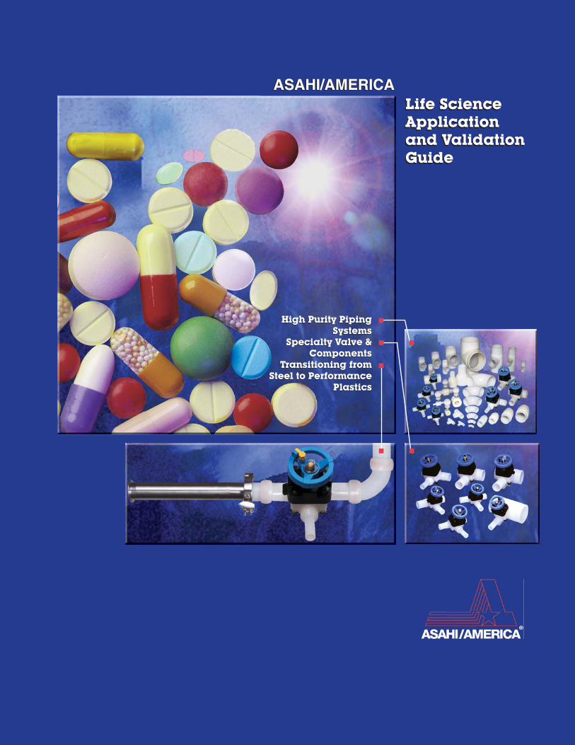
Section OneIntroduction
pg. 1
Section TwoApplication and Design:USP Purified Water pg. 5
Section ThreeAlternative Applicationsfor Thermoplastics pg. 13
Section FourMaterial Comparisons
pg. 21
Section FiveValidation Plan andSample Protocols pg. 29
Section SixMaterials andSystems Overview pg. 33
Section SevenPiping Design: High PurityWater Systems pg. 47
Section EightSpecifications
pg. 57
Purad® PVDFSDR21, PN16/230psi, Sizes 20-280mmSDR33, PN10/150ps1, Sizes 90-315mm
PolyPureTM, Natural PPSDR11, PN11/150psi, Sizes 20-110mm
Proline® Pigmented PPSDR11, PN11/150psi, Sizes 20-500mm
Also Available as SDR17 and SDR32.5
Ultra Proline® E-CTFESDR21, PN10/150psi, Sizes 32, 50, 63, 90 and110mm
Asahi/America Application and Validation Guide Life Science Application and Validation Guide
Purad, PolyPure, Proline and Ultra Proline are Trademarks of Asahi/America, Inc.

35 Green Street - Malden, MAPhone: (781) 321-5409 Fax: (781) 321-4421www.asahi-america.com
1ASAHI/AMERICA
APP-02
Asahi/America Application and Validation GuideSection One: Introduction
Sectio
n 1
This guide contains many possible applications but itsmain focus is on High Purity Water. High Purity WaterProduction is perhaps the most visible and importantsystem in a Biopharmaceutical manufacturing facility.As a critical system evaluated for facility licensing, thewater system’s importance cannot be overstated. TheFDA utilizes the water system as a benchmark indicatorof a facility’s current Good Manufacturing Practice(cGMP) suitability because it is an universal compo-nent, regardless of the intended application.
The major goal of this application guide is to provide ahigh purity water design philosophy to economicallyimprove the quality, reliability, and broaden the utiliza-tion of Purified Water (PW) systems in pharmaceuticalmanufacturing. Too much emphasis has been placedupon the “regulatory perceptions” of pharmaceuticalwater systems at the expense of the water quality. PWsystems must fulfill their role as the primary watersource for most pharmaceutical applications, andexpensive Water For Injection (WFI) should be rel-egated only to applications as defined by the name;water for injection.
The conceded microbiological integrity of WFI comesat a price; high cost, low purity and high metalscontent. Too often, WFI grade water is chosen to meetall facility applications, without regard to quality, toavoid regulatory scrutiny. This is costly both technicallyand economically. WFI water is not a high grade ofwater. WFI grade water is in contact with the atmo-sphere and, when piped in stainless steel, has analarming metals content (see graph on page 2).Rouging has been treated as an unfortunate byproductof pharmaceutical water quality and not recognized asthe gross contaminant that it is. Hot WFI water,recirculating in 316 L Stainless Steel pipe, will consis-tently contain Iron, Molybdenum, Tungsten, Chrome,Nickel and Cobalt, as well as Copper, Zinc and tracesof other heavy metals.
· Metal laden WFI water, which has a significantcarbon dioxide content, is not suitable for mostlaboratory, research or chromatographic applica-tions. The water quality varies and is difficult toreproduce from facility to facility. There is a con-cern that this water impairs some cell cultureprocesses as well.
· Hot WFI water can be 10X more expensive thanthe higher quality DI alternative.
· Hot WFI requires expensive utilities support andposes safety risks due to its high temperature.
High purity DI water should replace low purity WFIwater in all applications except the final purification ofparenterals.
A high purity or DI water system should meet thefollowing objectives:
1) Economically provide high purity water ofexceedingly high quality, suitable for all applica-tions.
2) Provide water without disruption 24/7/365
3) Provide water of suitable quality and consis-tency so as to eliminated water as a variable inresearch and manufacturing.
High quality Purified Water will fulfill virtually all of thetechnical water requirements of the BioPharm industry.PW quality should not be measured by the minimalregulatory definition of PW, but be defined as thestandard of quality routinely delivered by a DI watersystem.
· The water should have a TOC less than 50 ppb,preferably less than 10 ppb.
· The microbial activity should be less than onecolony forming unit (cfu/ml), and typically muchless.
· The water should have no detectable endotoxin.
· The water should exceed 17.5 MegOhm resistiv-ity and there should be no detectable fluctuationsin quality, day to day, year to year.
· The DI water contains no detectable ions to onepart per billion.
· The water should require no heating or cooling tomaintain quality.
· The water quality is reproducible from facility tofacility and is easily scaled up.
· The DI water must be piped in thermoplasticmaterials and be provided on an instantaneousbasis, suitable for all applications, including thefeed source of the WFI make up.
Section OneIntroduction

35 Green Street - Malden, MAPhone: (781) 321-5409 Fax: (781) 321-4421
www.asahi-america.com2
ASAHI/AMERICAAPP-02
Asahi/America Application and Validation Guide Section One: Introduction
Sec
tio
n 1
PW should comprise the bulk of a facility’s water usewith WFI utilized on an “as directed” basis. Thisapproach provides high quality water on demand withconsiderable savings on utility infrastructure andsupport, operating expense and capital equipmentsavings. This application guide is provided to assistpharmaceutical engineers to apply these conceptsbased upon a wealth of real world application andexperience. The goal is to improve pharmaceuticalwater quality, reliability and efficiency. This applicationguide will also investigate other functions in the facilitywhere thermoplastic products can be applied to in-crease productivity and improve quality.
Asahi/America - The CompanyAsahi/America pioneered the development of corrosionresistant thermoplastic fluid flow products in the UnitedStates. As a leader in thermoplastic fluid flow products,Asahi/America offers expertise in product, systemdesign and installation. This approach is the TotalSystems Approach. With a focus on high purity and DIwater applications, Asahi/America’s knowledge in theapplication is the foundation for products to meet the
challenges of the industry. An Asahi/America system isspecified with confidence.
With superior product design and ISO 9001 manufac-turing, Asahi/America has remarkable product breadth.Valves and pipe are offered in numerous thermoplasticmaterials, and range from ¼” to 24”. Offerings includepneumatic and electric actuators, thermoplastic com-pressed air and ventilation/exhaust systems, andextensive custom fabrication.
Products are available through one of the industry’slargest distributor networks, nearly 1000 locationsnationally and throughout Latin America. Customersupport comes from knowledgeable distributors andfrom a sales and engineering staff dedicated to ther-moplastic system design.
Please feel free to contact the Asahi/America expertswith any questions about its products and how they fityour pharmaceutical and biopharmaceutical applica-tions. Asahi-America - The Wet Process People
FIGURE 1.A: ION CONTAMINATION COMPARISON BETWEEN FOUR ACTUAL HP INSTALLATIONS. ION CHROMOTOGRAPHY MEASURE-MENTS TAKEN ON DYNAMIC WATER SAMPLES DEPICT EXPECTED PURITY LEVELS BETWEEN POLYMER AND STAINLESS SYSTEMS.
Al Ba B Ca Cr Co Cu Fe Mg Mn Mo Ni K Si Na Sr W Zn
0.0001
0.001
0.01
0.1
1
10
100
ppb
Elements
HP PVDF vs. 316L SS Pipe
316L Stainless SteelBiotech Systems
High Purity PVDF Semiconductor Systems

35 Green Street - Malden, MAPhone: (781) 321-5409 Fax: (781) 321-4421www.asahi-america.com
3ASAHI/AMERICA
APP-02
Asahi/America Application and Validation GuideSection One: Introduction
Sectio
n 1
1.1 PURPOSE OF THIS GUIDE
This guide is presented in a unique format, a total standalone document which answers questions for the design,construction, commissioning and validation of a pharma-ceutical PW system or process application. It is acombination handbook and textbook to guide youthrough the entire process from conception to successfuloperation.
This guide is a source of information for pharmaceuti-cal and biopharmaceutical managers who need tomake critical decisions in regard to process systems. Itis directed to high purity applications and takes youthrough conception, validation and successful opera-tion.
It is organized in such a way to lead the user throughthe steps in the design and construction of an engi-neering project.
Asahi/America is prepared to assist you in all phasesof a project from start to finish to make your planningand installation as smooth as possible.
1.2 HOW TO USE THIS GUIDE
The following is a suggested approach to a typicalproject:
1. Select your application from the following catego-ries or create a new possible application:
- USP Purified Water- Water for Injection (WFI)- Solution and Buffer Preparation- Fermentation or Cell Culture Media Preparation- Clean in Place Systems (CIP)- Pure Air and Gasses- Equipment Hook-up
2. Refer to our generic designs which are shown inSections 4 and 5. Section 4, (USP Purified Water)includes a basic list of equipment, valves, piping andinstrumentation. Also included is information onrecommended materials of construction.
3. Define the project including a schedule.
4. Create a preliminary Process Flow Diagram (PFD)
5. Create Specifications (Refer to the Section 8 forthe specifications of our products).
6. Prepare a Process and Instrumentation Drawing(P&ID).
7. Prepare Equipment and Materials List.
8. Prepare a validation plan.
9. Order the equipment and materials.
10. Prepare construction and piping drawingsincluding isometrics.
11. Prepare construction schedule.
12. Startup and commissioning
13. Validation
14. Operation
Asahi/America Application and Validation Guide
35 Green Street - Malden, MAPhone: (781) 321-5409 Fax: (781) 321-4421www.asahi-america.com
5ASAHI/AMERICA
APP-02
Section Two: Applications andDesign - USP Purified Water
Sectio
n 2
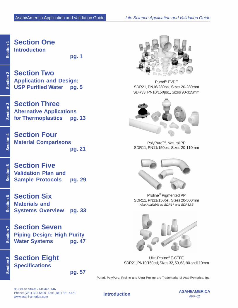
Classification Purified WFIStandard
RO/DISuggested
Levels
Resistivity(MΩ/cm)
< 1 < 1 17.5 18.1
Conductivity (µS)
< 1 < 1 0.057 0.056
TOC(ppb)
< 500 < 500 < 50 < 5
Bacteria*(cfu/100ml)
< 10,000 10 < 100 < 10
Endotoxin(EU)
NA < 0.25 < 0.25 < 0.03
As stated in the introduction the major goal of thisapplication guide is to provide a high purity water designphilosophy to economically improve the quality, reliabilityand broaden the utilization of Purified Water systems inpharmaceutical manufacturing. Purified Water systemsmust fulfill their role as the primary water source for mostpharmaceutical applications. Expensive WFI watershould be relegated only to applications as defined bythe name, Water for Injection.
Based on the premise that Purified Water (PW) systemsshould be the major water source in a manufacturing andlab facility, it then needs to be economical and reliable.Proper utilization of thermoplastic piping systems fromAsahi/America is part of the equation. The design optionsprovided in section 4.1 are provided to better understandPW systems and the use of thermoplastics within thesesystems.
2.1 USP Purified Water (USP 25)
This is the most common type of high purity water usedin the pharmaceutical and biopharmaceutical industries.It may possibly be the most important system in thefacility, considering so much importance rides on thequality of the purified water and its relation to the successof the validation and licensing of a manufacturing facility.Problems with a PW system invite more scrutiny on thequality of the rest of the manufacturing process. PWsystems that vastly exceed expectations emphasize thequality of the enterprise as a whole.
Purified Water is frequently misunderstood. It is techni-cally a relatively low grade of high purity water at one ΜΩ,500 ppb TOC (Total Organic Carbon) and a liberal bacteriacount of 100 cfu/ml.* The designation PW quality, is aregulatory designation, and often higher product waterquality is actually desired. It is important not to confuseor combine regulatory specifications with product waterquality requirements. From a design viewpoint,
higher water quality is actually required to maintainmicrobial control. Any credible thermoplastic(RO/DI) water system design should make water that is17.5 ΜΩ (0.055 uS), TOC < 50 ppb and bacteria at about1 cfu/ml. By properly utilizing TOC UV lamps in thedesign, the water should be less than 10 ppb TOC, andbacteria at considerably less than one cfu/ml.
2.2 System Design
2.2.1 Design PhilosophyGenerally speaking, it is not recommended to utilize achemical addition approach to water treatment.Sequestrants, dispersing agents, chlorine addition andbisulfite additions all add chemicals that eventually haveto be removed again. The pretreatment should rely uponbackwashable filter media for suspended solids removal,not cartridge filtration alone. A high purity water systemshould be based upon reverse osmosis, for economicand technical reasons. If ion exchange resins and a TOCUV light unit are properly utilized, there is no reason thesystem cannot provide the following design goals:
1. Exceedingly high quality Ultra Pure Water (seeSuggested Levels for Table 2.1)
2. No detectable product water quality fluctuations.3. Reduced capital investment4. Minimal operating costs5. Virtually no maintenance except for one scheduled
maintenance day per year.
These goals are routinely achieved in the semiconduc-tor industry and have become more common in thebiopharmaceutical water systems. With the use ofproper design and thermoplastic materials truly re-markable water quality is becoming routine.
TABLE 2.1 WATER QUALITY COMPARISON
*The Pharmaceutical Industry usually utilizes a WFI product waterspecification of 10 cfu’s/ ml by convention. Actually there is nobacteria specification in the Pharmacopoeia for either Purified or WFIwater, but the FDA still enforces USP 22 microbiological require-ments.
Section TwoApplications and DesignUSP Purified Water

Asahi/America Application and Validation Guide
35 Green Street - Malden, MAPhone: (781) 321-5409 Fax: (781) 321-4421
www.asahi-america.com6
Section Two: Applications andDesign - USP Purified Water
ASAHI/AMERICAAPP-02
Sec
tio
n 2
Pipe Size Flow Range System
mm (inches) (gpm) Length (ft) PVDF PP
32 (1) 10-15 500 2.16 - 4.57 2.70 - 5.72
50 (1½ ) 25 - 35 1,500 1.11 - 2.08 1.64 - 3.49
63 (2) 50 - 70 2,000 1.17 - 2.18 1.93 - 3.60
90 (3) 65 - 90 3,000 0.25 - 0.49 0.75 - 1.22
Pressure Drop per 100ft
It is exceedingly difficult, if at all possible, to constrainmicrobiology in the pretreatment vessels and in storagetanks. A microbiological control strategy is to allownormal levels of microbiological activity in the pretreat-ment and storage tanks, but to prevent inoculation of thedistribution loop, and retard growth of organisms in theproduct water.
Pretreatment of bacteria prior to the RO have virtually norelation or effect upon bacteria levels after the RO unitdue to the almost impenetrable RO membrane. Microbi-ology in plastic storage tanks should stabilize at no morethan 20 cfu/ml, and are typically in the 1 cfu/ml range.There should be no or just barely detectable slime layerunder the water line of a DI storage tank. One should bevery concerned with effective microbial control after thestorage tank. Control microbiology in the distribution loopby preventing the inoculation of the distribution loop witha 3 stage barrier to microbes (post treatment) and bymaking the product water inhospitable to by operating atless than 10 ppb TOC in the distribution loop. Bacteriawill always be present in a distribution loop, but if there isno food (i.e.; TOC) in the distribution loop, bacteria maysurvive, but they cannot thrive. Microorganisms shouldstay almost irreversibly attached to the hydrophobicsurfaces of plastic pipe, resulting in virtually no detect-able bugs in the bulk phase product water.
2.2.2 System SizingWater systems are best sized by their distribution loops(typically 1”, 1 ½”, 2.0 “ or 3.0 “ for USP systems). Youfirst must know approximately how much water you needto provide, on an instantaneous basis, and on a dailybasis/shift. Instantaneous water usage should notexceed 1/3 the distribution loop flow rate for semiconduc-tors, and 1/2 the distribution flow rate for Bio-Pharmwhere pressure and flow stability are not as critical. Theinstantaneous usage sizes the required post treatmentand distribution loop or loops. The daily usage sizes theRO make up capacity and the storage tank(s).
In addition to the Table 2.2, please refer Asahi/America’sEngineering Design guide for complete listings ofpressure drops and fluid velocities based on total flowthrough a pipe diameter.
The storage tank should be sized proportionally with theRO unit to provide design balance. A rule of thumb is theRO unit should be capable of filling the tank in no lessthan an hour and no more than 3 hours. The RO sizesthe required pretreatment and feedwater piping andheating (if used) requirements. You can then figure oututilities, electrical, floor drains and room sizing.
2.3 Process Design
The design of a Purified Water system can be brokendown into four sections of design consideration:
1. Feed Water2. Pretreatment3. Purification4. Post Treatment
Each of these categories can be further broken downinto the details of the equipment utilized and specificpiping layout.
2.3.1 Process Design: Feed WaterThe feed water is either city water or on site well water.The feed water must meet EPA potability standards, orthe system must address any feed water quality deficien-cies. The feed may be surface water or well water, or acombination. Surface waters are often characterized bylow salt content and suspended solids that foul RO units.Well waters are often free of suspended solids, but havea high salt content that consumes mixed bed polisher lifeafter the RO.
The municipal treatment plant, phone numbers, treat-ment process and chemical additions supplied in thedrinking water should be known and taken into consider-ation when designing a water system. The presence ofchloramines, elevated pH and chemical coagulants allmay cause considerable problems if not addressed fromthe beginning.
Following the initial feedwater, standard RODI watersystem design is best divided into three stages. They areconveniently classified as: Pretreatment, Purification andPost Treatment.
TABLE 2.2 SUGGESTED SYSTEM FLOW RATES AND SIZES
Asahi/America Application and Validation Guide
35 Green Street - Malden, MAPhone: (781) 321-5409 Fax: (781) 321-4421www.asahi-america.com
7ASAHI/AMERICA
APP-02
Section Two: Applications andDesign - USP Purified Water
Sectio
n 2
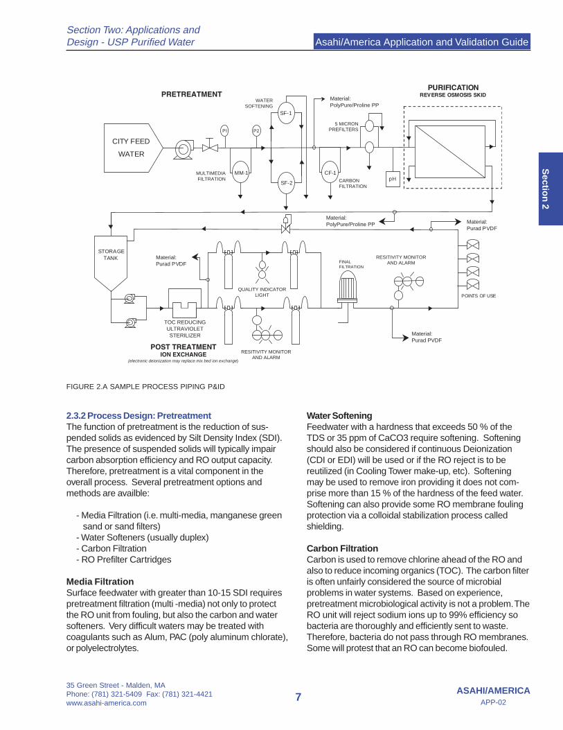
2.3.2 Process Design: PretreatmentThe function of pretreatment is the reduction of sus-pended solids as evidenced by Silt Density Index (SDI).The presence of suspended solids will typically impaircarbon absorption efficiency and RO output capacity.Therefore, pretreatment is a vital component in theoverall process. Several pretreatment options andmethods are availble:
- Media Filtration (i.e. multi-media, manganese greensand or sand filters)
- Water Softeners (usually duplex)- Carbon Filtration- RO Prefilter Cartridges
Media FiltrationSurface feedwater with greater than 10-15 SDI requirespretreatment filtration (multi -media) not only to protectthe RO unit from fouling, but also the carbon and watersofteners. Very difficult waters may be treated withcoagulants such as Alum, PAC (poly aluminum chlorate),or polyelectrolytes.
Water SofteningFeedwater with a hardness that exceeds 50 % of theTDS or 35 ppm of CaCO3 require softening. Softeningshould also be considered if continuous Deionization(CDI or EDI) will be used or if the RO reject is to bereutilized (in Cooling Tower make-up, etc). Softeningmay be used to remove iron providing it does not com-prise more than 15 % of the hardness of the feed water.Softening can also provide some RO membrane foulingprotection via a colloidal stabilization process calledshielding.
Carbon FiltrationCarbon is used to remove chlorine ahead of the RO andalso to reduce incoming organics (TOC). The carbon filteris often unfairly considered the source of microbialproblems in water systems. Based on experience,pretreatment microbiological activity is not a problem. TheRO unit will reject sodium ions up to 99% efficiency sobacteria are thoroughly and efficiently sent to waste.Therefore, bacteria do not pass through RO membranes.Some will protest that an RO can become biofouled.
FIGURE 2.A SAMPLE PROCESS PIPING P&ID
CITY FEED
WATER
MM-1pH
STORAGETANK
POINTS OF USE
PI P2
SF-2
SF-1
CF-1
PURIFICATIONREVERSE OSMOSIS SKIDPRETREATMENT
Material:Purad PVDF
Material:Purad PVDF
Material:Purad PVDF
TOC REDUCINGULTRAVIOLET STERILIZER
RESITIVITY MONITOR AND ALARM
POST TREATMENTION EXCHANGE
QUALITY INDICATOR LIGHT
RESITIVITY MONITOR AND ALARM
5 MICRONPREFILTERS
CARBONFILTRATION
WATERSOFTENING
MULTIMEDIAFILTRATION
Material:PolyPure/Proline PP
Material:PolyPure/Proline PP
FINAL FILTRATION
(electronic deionization may replace mix bed ion exchange)

Asahi/America Application and Validation Guide
35 Green Street - Malden, MAPhone: (781) 321-5409 Fax: (781) 321-4421
www.asahi-america.com8
Section Two: Applications andDesign - USP Purified Water
ASAHI/AMERICAAPP-02
Sec
tio
n 2
Property Coconut Coal Lignite Wood
Micropore High High Medium Low
Macropore Low Medium High High
Hardness High High Low Medium
Ash (percent) 5 10 20 5
Water Soluble Ash High Low High Medium
Dust Low Medium High Medium
Regeneration Good Good Poor Fair
Density (g/cm3) 0.42 0.48 0.3 0.35
Iodine # (mg/gm) 1100 1000 600 1000
Biofouled TFC RO membranes are a symptom of poor ROdesign or insufficient pretreatment filtration resulting infouling of the RO membranes. The fouled RO membranesprovide a food source that quickly slimes over (instantbiofilm). The RO often fouls on surface feedwater due toexcessively high conversions (RO product vs reject ratio)or reject water recirculation to conserve water, both ofwhich are a function of proper RO design per application.In lieu of carbon pretreatment, a bisulfite addition issometimes utilized to neutralize chlorine. Bacteria canmetabolize the bisulfite itself, that plus the lack of anadditional filtration step, can also result in biofouling.Bisulfite additions in place of carbon filtration may alsoresults in excess TOC in the product water. High TOClevels can result in product water bacteria.
Therefore, the use of carbon in pretreatment is preferred.Carbon pretreatment effectively removes chlorine mol-ecules and does not contribute to TOC build up. Carbonbeds do not require steam or hot water sanitization, as itdoes not enhance performance.
Carbon in pretreatment is found as Granular ActivatedCarbon (GAC). GAC uses surface area to absorb (trap)impurities. GAC is an effective filtration method and canhave a surface area of 1000 – 1200 square meters pergram. This is equal to 100 football fields laid out side byside per pound of GAC
GAC types are distinguished by raw materials and poresize distribution. Other properties include Iodine, carbontetrachloride activity, surface area, pore volume, moisturecontent, particle size distribution, mean particle size, andsoluble ash content. The Table 2.3 lists the most commonGAC Types and their properties.
Coconut Shell - Low ash (5%), low dust, better on low
molecular weight Organics due to smaller interstitialpore spaces. High Micropore density, low Macroporedensity.
Coal based - Bituminous (Steam) Activated Carbon -cheaper, may be dirtier, higher ash (10%) content,medium dust content. Good physical stability (Abrasion#). High micropore & medium macropore density toremove wider molecular range of organics.
Lignite Based - a low ranked coal. GAC made fromlignite has a large pore size. This may result in higherTOC removal capacity, perhaps for large fulvic andhumic acids (organics). This higher capacity may beoffset by reduced physical integrity and high finescontent.
Wood based Carbon – Low Micropore & HighMacropore density. Ash content (5%), dust level High.
Acid washed Carbon (low to no ash due to acidwashing) Low pH > 2, phosphoric acid washed, maydamage older RO membranes if not rinsed properly.
NOTE: Check pH of feedwater and new carboneffluent. High pH (approximate 10) due to ash throwmay cause a significant loss of RO membrane ionrejection. This may occur in non-acid washed (highash) carbon.
Coconut shell carbon is recommended for chloramineremoval due to the propensity of micropores presentwhen compared to coal based carbon. Beware though,Coconut shell carbon may foul more quickly on themacromolecular TOC found in surface water sources.Further, a long path (high column or dual beds in series)is recommended for chloramine removal, due to theslow reaction rate and the formation of carbon oxidesfrom chloramine removal.
In surface waters with chloramines, a safe path may be touse a tall (72 inch straight shell) vessel with coal basedGAC. In severe cases, coal based GAC may be used inthe primary bed, followed by a coconut shell carbon forchloramines in a second carbon bed, operated in series.
Other chloramine removal techniques involve chloraminedestruction via the addition of sodium hypochlorite and UVdissociation of chloramines utilizing intense levels of high-pressure UV lamp irradiation.
TABLE 2.3 ACTIVE CARBON COMPARISON Source: Henry G.Nowicki; Water Technology; March 1997
Asahi/America Application and Validation Guide
35 Green Street - Malden, MAPhone: (781) 321-5409 Fax: (781) 321-4421www.asahi-america.com
9ASAHI/AMERICA
APP-02
Section Two: Applications andDesign - USP Purified Water
Sectio
n 2
2.3.3 Process Design: PurificationThe function of purification is to remove dissolvedimpurities. The presence of suspended solids willimpair most purification technologies.
The Purification phase of treatment deals with dissolvedimpurities, primarily salts or ions.* All high purity watersystems should employ an RO unit. This is importantbecause the RO membrane provides an impenetrablebarrier to all solids, including colloids and microbesfound in the city feed. Without this barrier, problemsdownstream will eventually become overwhelming. Thisis especially true for microbial related issues.
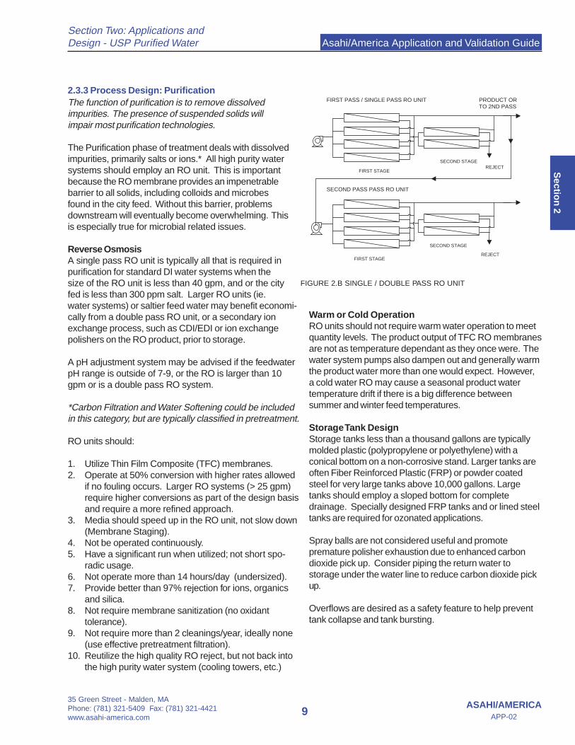
Reverse OsmosisA single pass RO unit is typically all that is required inpurification for standard DI water systems when thesize of the RO unit is less than 40 gpm, and or the cityfed is less than 300 ppm salt. Larger RO units (ie.water systems) or saltier feed water may benefit economi-cally from a double pass RO unit, or a secondary ionexchange process, such as CDI/EDI or ion exchangepolishers on the RO product, prior to storage.
A pH adjustment system may be advised if the feedwaterpH range is outside of 7-9, or the RO is larger than 10gpm or is a double pass RO system.
*Carbon Filtration and Water Softening could be includedin this category, but are typically classified in pretreatment.
RO units should:
1. Utilize Thin Film Composite (TFC) membranes.2. Operate at 50% conversion with higher rates allowed
if no fouling occurs. Larger RO systems (> 25 gpm)require higher conversions as part of the design basisand require a more refined approach.
3. Media should speed up in the RO unit, not slow down(Membrane Staging).
4. Not be operated continuously.5. Have a significant run when utilized; not short spo-
radic usage.6. Not operate more than 14 hours/day (undersized).7. Provide better than 97% rejection for ions, organics
and silica.8. Not require membrane sanitization (no oxidant
tolerance).9. Not require more than 2 cleanings/year, ideally none
(use effective pretreatment filtration).10. Reutilize the high quality RO reject, but not back into
the high purity water system (cooling towers, etc.)
Warm or Cold OperationRO units should not require warm water operation to meetquantity levels. The product output of TFC RO membranesare not as temperature dependant as they once were. Thewater system pumps also dampen out and generally warmthe product water more than one would expect. However,a cold water RO may cause a seasonal product watertemperature drift if there is a big difference betweensummer and winter feed temperatures.
Storage Tank DesignStorage tanks less than a thousand gallons are typicallymolded plastic (polypropylene or polyethylene) with aconical bottom on a non-corrosive stand. Larger tanks areoften Fiber Reinforced Plastic (FRP) or powder coatedsteel for very large tanks above 10,000 gallons. Largetanks should employ a sloped bottom for completedrainage. Specially designed FRP tanks and or lined steeltanks are required for ozonated applications.
Spray balls are not considered useful and promotepremature polisher exhaustion due to enhanced carbondioxide pick up. Consider piping the return water tostorage under the water line to reduce carbon dioxide pickup.
Overflows are desired as a safety feature to help preventtank collapse and tank bursting.
FIRST STAGE
SECOND STAGEREJECT
FIRST STAGE
SECOND STAGE
REJECT
FIRST PASS / SINGLE PASS RO UNIT
SECOND PASS PASS RO UNIT
PRODUCT ORTO 2ND PASS
FIGURE 2.B SINGLE / DOUBLE PASS RO UNIT
Asahi/America Application and Validation Guide
35 Green Street - Malden, MAPhone: (781) 321-5409 Fax: (781) 321-4421
www.asahi-america.com10
Section Two: Applications andDesign - USP Purified Water
ASAHI/AMERICAAPP-02
Sec
tio
n 2
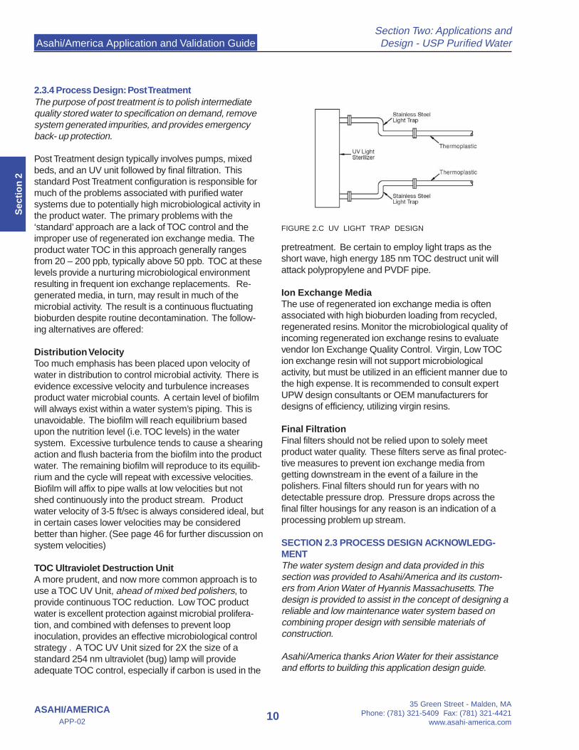
pretreatment. Be certain to employ light traps as theshort wave, high energy 185 nm TOC destruct unit willattack polypropylene and PVDF pipe.
Ion Exchange MediaThe use of regenerated ion exchange media is oftenassociated with high bioburden loading from recycled,regenerated resins. Monitor the microbiological quality ofincoming regenerated ion exchange resins to evaluatevendor Ion Exchange Quality Control. Virgin, Low TOCion exchange resin will not support microbiologicalactivity, but must be utilized in an efficient manner due tothe high expense. It is recommended to consult expertUPW design consultants or OEM manufacturers fordesigns of efficiency, utilizing virgin resins.
Final FiltrationFinal filters should not be relied upon to solely meetproduct water quality. These filters serve as final protec-tive measures to prevent ion exchange media fromgetting downstream in the event of a failure in thepolishers. Final filters should run for years with nodetectable pressure drop. Pressure drops across thefinal filter housings for any reason is an indication of aprocessing problem up stream.
SECTION 2.3 PROCESS DESIGN ACKNOWLEDG-MENTThe water system design and data provided in thissection was provided to Asahi/America and its custom-ers from Arion Water of Hyannis Massachusetts. Thedesign is provided to assist in the concept of designing areliable and low maintenance water system based oncombining proper design with sensible materials ofconstruction.
Asahi/America thanks Arion Water for their assistanceand efforts to building this application design guide.
2.3.4 Process Design: Post TreatmentThe purpose of post treatment is to polish intermediatequality stored water to specification on demand, removesystem generated impurities, and provides emergencyback- up protection.
Post Treatment design typically involves pumps, mixedbeds, and an UV unit followed by final filtration. Thisstandard Post Treatment configuration is responsible formuch of the problems associated with purified watersystems due to potentially high microbiological activity inthe product water. The primary problems with the‘standard’ approach are a lack of TOC control and theimproper use of regenerated ion exchange media. Theproduct water TOC in this approach generally rangesfrom 20 – 200 ppb, typically above 50 ppb. TOC at theselevels provide a nurturing microbiological environmentresulting in frequent ion exchange replacements. Re-generated media, in turn, may result in much of themicrobial activity. The result is a continuous fluctuatingbioburden despite routine decontamination. The follow-ing alternatives are offered:
Distribution VelocityToo much emphasis has been placed upon velocity ofwater in distribution to control microbial activity. There isevidence excessive velocity and turbulence increasesproduct water microbial counts. A certain level of biofilmwill always exist within a water system’s piping. This isunavoidable. The biofilm will reach equilibrium basedupon the nutrition level (i.e. TOC levels) in the watersystem. Excessive turbulence tends to cause a shearingaction and flush bacteria from the biofilm into the productwater. The remaining biofilm will reproduce to its equilib-rium and the cycle will repeat with excessive velocities.Biofilm will affix to pipe walls at low velocities but notshed continuously into the product stream. Productwater velocity of 3-5 ft/sec is always considered ideal, butin certain cases lower velocities may be consideredbetter than higher. (See page 46 for further discussion onsystem velocities)
TOC Ultraviolet Destruction UnitA more prudent, and now more common approach is touse a TOC UV Unit, ahead of mixed bed polishers, toprovide continuous TOC reduction. Low TOC productwater is excellent protection against microbial prolifera-tion, and combined with defenses to prevent loopinoculation, provides an effective microbiological controlstrategy . A TOC UV Unit sized for 2X the size of astandard 254 nm ultraviolet (bug) lamp will provideadequate TOC control, especially if carbon is used in the
FIGURE 2.C UV LIGHT TRAP DESIGN

Asahi/America Application and Validation Guide
35 Green Street - Malden, MAPhone: (781) 321-5409 Fax: (781) 321-4421www.asahi-america.com
11ASAHI/AMERICA
APP-02
Section Two: Applications andDesign - USP Purified Water
Sectio
n 2
SystemDescription
RecommendedMaterial
ProductName
MaximumTemperature
PretreatmentPigmented PP
Natural PPProline
PolyPure195°F
Post TreatmentNatural PPHP PVDF
PolyPurePurad
195°F
Distribution LoopNatural PPHP PVDF
PolyPurePurad
250°F
TABLE 2.4 MATERIALS OF CONTRUSTION BY APPLICATION*See Section 7 for discussion on SIP parameters
2.4 Materials of Construction
Many polymeric materials are used in the design of aUSP Purified Water System. In the pretreatment section,the material of choice has been polyvinyl chloride (PVC)or chlorinated polyvinyl chloride (CPVC). They are verycost effective with easy installation and maintenance. Inrecent years the use of PVC has started to decline infavor of Polypropylene. Polypropylene offers thermalwelding techniques similar to the purification and posttreatment sections and offers enhanced purity properties.Thermal welding eliminates solvent cement in thesystem, which is a major contributor to TOC. Many PWsystems are exceptionally served by the use of PPthroughout the entire system.
filtration. PVC contains an enormous amount of process-ing agents and solvent cement joining techniques addTOC to the system.
It is equally important only to accept systems specificallymanufactured and engineered for high purity applica-tions. PP and PVDF systems are manufactured with avariety of resins and manufacturing techniques. Not allsystems are the same. Many production techniques aresuited for industrial applications but are detrimental tosystem purity. At a minimum, all valves, fittings andpiping should be produced in a clean environment andpackaged to protect product cleanliness. Pipe shouldbe capped and bagged immediately after production.Furthermore, all fittings and valves should be rinsed withDI water before individual packaging.
The evaluation and selection of materials will have adirect impact on system quality. A complete review ofavailable materials and joining methods is recom-mended. Section Eight contains detailed productspecifications and Asahi/America’s Engineering DesignGuide is and excellent source of information for designand installation requirements.
Finally, a comparison between thermoplastic andstainless systems is found in Section Four and moredetailed information on thermoplastic system propertiesis contained in Section Six of this guide.
In post treatment (which is the material immediately afterthe reverse osmosis unit) PP or PVDF should be utilizeddue to its superior purity compared to other materials.The requirements for water quality and system cleaningtechniques are the determining factor for which materialshould be utilized. Polypropylene is a clean and smoothmaterial that can operate up to 195°F. PVDF offerssuperior purity and surface finish over polypropylene andcan withstand most chemicals used in cleaning as wellas ozone sanitization. For exact recommendations onoperating conditions, contact Asahi/America’s Engineer-ing Department for assistance.
2.4.1 MATERIAL PURITYHigh performance thermoplastics, much like high gradesof stainless steel, should be manufactured, packagedand installed in clean environments. Only pure resinsand materials should be specified for PW and WFIapplications. Materials which use excessive additives,stabilizers or un-pure joining techniques should beavoided as they are potential water contaminationsources. Using components made of PVC should bediscouraged for anything after the initial pretreatment
Asahi/America Application and Validation Guide
35 Green Street - Malden, MAPhone: (781) 321-5409 Fax: (781) 321-4421www.asahi-america.com
13ASAHI/AMERICA
APP-02
Section Three: Alternate Applicationsfor Thermoplastic Systems
Sectio
n 3
System Description Material BrandMaterial
Temp. RatingAmbient Pressure
Rating Application
Purified WaterNatural PP
PVDFPolyPure
Purad20 to 80°C 150 psi Ambient DI Water
WFI*316/316L SS
PVDF-230N.A.
Purad-
121-130°C*-
150/230 psiHot Water
Solution Prep316/316L SS
PVDF-230N.A.
Purad-
121-130°C*-
150/230 psiVaries
Fermentation and cell culture media prep
316/316L SSPVDF-230
N.A.Purad
-121-130°C*
-150/230 psi
Varies
Clean-in-Place (CIP)Polypropylene
PVDFE-CTFE
ProlinePuradHalar
< 95°C< 121°C< 121°C
150 psi150/230 psi
150 psi
Material selection based upon compatibility with
cleaning agents
Pure Air and GasesEltex Tube124
HDPEAir-Pro 20 to 60°C 230 psi Pure Air and Gases
3.0 Scope
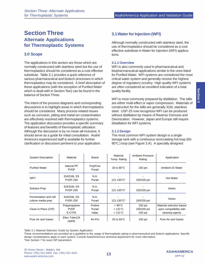
The applications in this section are those which arenormally constructed with stainless steel but the use ofthermoplastics should be considered as a cost effectivesubstitute. Table 3.1 provides a quick reference ofvarious pharmaceutical and biotech processes in whichthermoplastics may be considered. A brief description ofthese applications (with the exception of Purified Waterwhich is dealt with in Section Two) can be found in thebalance of Section Three.
The intent of the process diagrams and correspondingdiscussions is to highlight areas in which thermoplasticsshould be considered. Many process related issuessuch as corrosion, pitting and metal ion contaminationare effectively resolved with thermoplastics systems.The application discussion provides a specific summaryof features and benefits of thermoplastic utilization.Although the discussion is by no mean all-inclusive, itshould serve as a guide for initial consultation. Asahi/America’s experienced staff is available for furtherclarification or discussion pertinent to your application.
3.1 Water for Injection (WFI)
Although normally constructed with stainless steel, theuse of thermoplastics should be considered as a costeffective substitute in Water for Injection (WFI) applica-tions.
3.1.1 OverviewWFI is also commonly used in pharmaceutical andbiopharmaceutical applications similar to the ones listedfor Purified Water. WFI systems are considered the mostcritical water system and generally receive the highestdegree of regulatory scrutiny. High quality WFI systemsare often considered an excellent indication of a totalquality facility.
WFI is most commonly prepared by distillation. The stillsare either multi-effect or vapor compression. Materials ofconstruction for the stills are generally 316L stainlesssteel. USP-25 now recognizes WFI can be producedwithout distillation by means of Reverse Osmosis andDeionization. However, Japan and Europe still requiredistallation for WFI systems.
3.1.2 DesignThe most common WFI system design is a singlestorage tank with a continuous recirculating hot loop (65-80oC.) loop (see Figure 3.A). A specially designed
Section ThreeAlternate Applicationsfor Thermoplastic Systems
Table 3.1 Material Selection Guide by System ApplicationThese recommendations are provided as a guideline to the usage of thermoplastic piping in pharmaceutical and biotech applications. Specificdesign considerations apply to each system. Consult Asahi/America’s technical department for more information.*See Section 7 for exact SIP parameters

Asahi/America Application and Validation Guide
35 Green Street - Malden, MAPhone: (781) 321-5409 Fax: (781) 321-4421
www.asahi-america.com14
Section Three: Alternate Applicationsfor Thermoplastic Systems
ASAHI/AMERICAAPP-02
Sec
tio
n 3
cooled point of use or a separate ambient loop aresometimes employed. The other type is the batched tankwith a recirculating hot loop. This is almost exclusivelyused when QA release is required for actual preparationof injectable compounds.
3.1.3 Materials of ConstructionTraditionally WFI systems have been constructed using316L stainless steel. The semiconductor industry hasdemonstrated that PVDF is actually a better material ofconstruction in terms of both cost and vulnerability tocontamination. Please refer to Section Seven andconsult Asahi/America for exact conditions under whichPurad PVDF systems may be steam sterilized for WFIapplications.
3.1.4 System DesignThe following is a design option for a typical Water forInjection system utilizing distillation. A WFI Systemgenerates water, which meets USP 25 standards and isused in various operations to produce pharmaceuticaland biopharmaceutical products. The system consists ofa multi-effect or vapor compression still, a storage tankand a hot distribution loop.
Purified Water is fed to the still and by the process ofevaporation, impurities are removed. The vapors arecondensed by a heat exchanger and the water flows bygravity to the storage tank. The water is maintained atapproximately 65o to 80o C. and is pumped through thedistribution loop and back to the tank. There are hot andcooled Points of Use. Materials of construction histori-cally have been 316L stainless steel but Purad PVDFcan be substituted in many areas of the system, provid-ing improved purity.
UtilitiesFeed Water Purified WaterPlant Steam 70 to 110 psig.Clean Steam 45 to 75 psig. (optional)Instrument Air (80 psig. minimum)Cooling Water or Chilled Glycol
Feed Water Package (typical)This package is a 50 gallon tank with a level control anda vent filter. A 2 HP sanitary pump feeds the still.
FIGURE 3.A Single storage WFI PI&D
POINTS OF USE
Clean Steam Feed
To Heated Vent Filter
316L SS
Condensate
To Drain
50 psig Steam
Purad PVDF
Purad PVDF
Purad PVDF
WFIStill
WFI Storage Tank
316 SS
CondensateHeader
POINTS OF USEPOINTS OF USE
Clean Steam Feed
To Heated Vent Filter
316L SS
Condensate
To Drain
50 psig Steam
Purad PVDF
Purad PVDF
Purad PVDF
WFI Storage Tank
316 SS
CondensateHeader
Heat Exchanger(as needed)
Instrumentation Air
AirPro HDPE
Cooling Water Supply
Proline PP/PE
Cooling Water Return
Proline PP/PE
Purad PVDF
20 to 80˚C up to 230 psi
20 to 60˚C up to 230 psi
20 to 40˚C up to 150 psi
20 to 40˚C up to 150 psi
20 to 130˚C* up to 230 psi
20 to 130˚C* up to 230 psi
* = Please Consult Factory for exact pressure vs. temperature ratings of Purad PVDF and Steam In Place Applications
Purified Water FeedPurad PVDF
PurifiedWaterStorage
Asahi/America Application and Validation Guide
35 Green Street - Malden, MAPhone: (781) 321-5409 Fax: (781) 321-4421www.asahi-america.com
15ASAHI/AMERICA
APP-02
Section Three: Alternate Applicationsfor Thermoplastic Systems
Sectio
n 3
Still DescriptionFor a typical 4 effect unit, the first effect is heated by plantsteam and subsequent effects are heated by the productsteam from the previous shell and tube heat exchangers(effects). Only the first effect utilizes a double tube sheetdesign. The material of construction is 316L stainless steel.
CondenserThe condenser is a shell and tube heat exchangerlocated on the top of the still. Cold feed water andadditional cooling water is used for condensation. Puresteam enters from the evaporator heat exchangers(except the first effect). The top of the condenser isvented with a sterile cartridge filter. The pure distillatedrains out of the bottom through temperature andresistivity sensors, a diverter valve and finally to thestorage tank.
PreheatersWarm feedwater from the condenser enters the heateron the last effect. This helps to cool the hot overflow fromthe last column. The water then goes to the previouseffect and the process is repeated until it reaches the firsteffect where it is fed into the column as hot feed water.
ControlsThe still system is controlled by a PLC. The panel boardcontains the various alarm functions. A chart recorderprovides the temperature and quality information for thedistillate. If the distillate is out of specification, it will bediverted to drain. A clock recorder indicates the durationof the still operation.
The temperature and pressure in the distribution loop aremonitored and alarmed. Also monitored are the level inthe storage tank and resistivity at the still and loop return.
Storage TankThis is a 316L stainless steel insulated vessel. It is fittedwith level control, temperature element, rupture disc,spray ball, jacketed 0.2 micron vent filter and SIP con-nections.
Distribution LoopThe WFI is distributed by single or dual sanitary pumps.Points of use are cooled by heat exchangers or may beused hot. All points of use are fitted with sanitarydiaphragm valves. A back pressure regulating valvemaintains loop pressure. A heat exchanger downstreamof the pump is used to maintain the temperature of thewater in the loop return by means of a temperaturecontroller. A TOC meter is installed at the beginning of
the loop. It measures both conductivity and Total OrganicCarbon.
It is important to mention at this point that when utilizing aPVDF piping system for WFI, certain design requirements,such as thermal stress calculations and related expansionof the piping must be taken into consideration during thedesign process. For more information on thermoplasticpipe system design, please refer to Asahi/America’sEngineering Design Guide.
Asahi/America Application and Validation Guide
35 Green Street - Malden, MAPhone: (781) 321-5409 Fax: (781) 321-4421
www.asahi-america.com16
Section Three: Alternate Applicationsfor Thermoplastic Systems
ASAHI/AMERICAAPP-02
Sec
tio
n 3
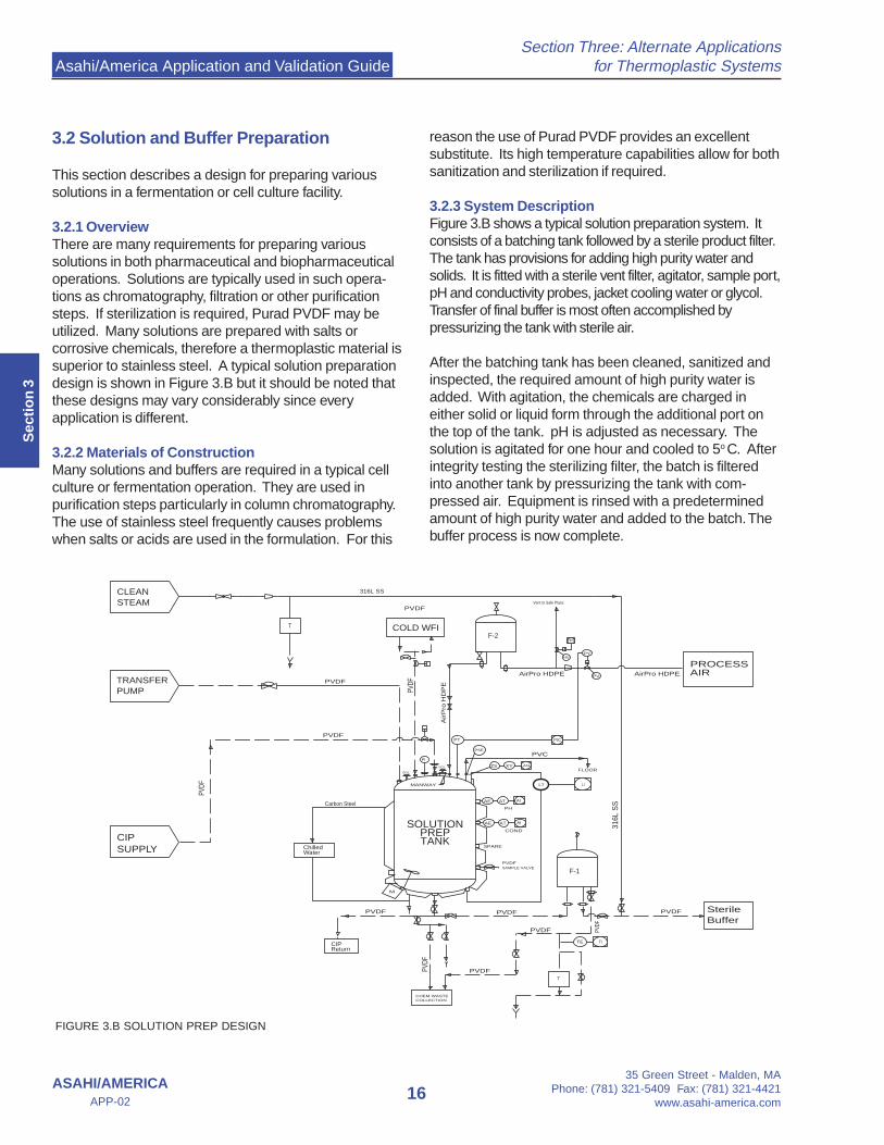
3.2 Solution and Buffer Preparation
This section describes a design for preparing varioussolutions in a fermentation or cell culture facility.
3.2.1 OverviewThere are many requirements for preparing varioussolutions in both pharmaceutical and biopharmaceuticaloperations. Solutions are typically used in such opera-tions as chromatography, filtration or other purificationsteps. If sterilization is required, Purad PVDF may beutilized. Many solutions are prepared with salts orcorrosive chemicals, therefore a thermoplastic material issuperior to stainless steel. A typical solution preparationdesign is shown in Figure 3.B but it should be noted thatthese designs may vary considerably since everyapplication is different.
3.2.2 Materials of ConstructionMany solutions and buffers are required in a typical cellculture or fermentation operation. They are used inpurification steps particularly in column chromatography.The use of stainless steel frequently causes problemswhen salts or acids are used in the formulation. For this
reason the use of Purad PVDF provides an excellentsubstitute. Its high temperature capabilities allow for bothsanitization and sterilization if required.
3.2.3 System DescriptionFigure 3.B shows a typical solution preparation system. Itconsists of a batching tank followed by a sterile product filter.The tank has provisions for adding high purity water andsolids. It is fitted with a sterile vent filter, agitator, sample port,pH and conductivity probes, jacket cooling water or glycol.Transfer of final buffer is most often accomplished bypressurizing the tank with sterile air.
After the batching tank has been cleaned, sanitized andinspected, the required amount of high purity water isadded. With agitation, the chemicals are charged ineither solid or liquid form through the additional port onthe top of the tank. pH is adjusted as necessary. Thesolution is agitated for one hour and cooled to 5o C. Afterintegrity testing the sterilizing filter, the batch is filteredinto another tank by pressurizing the tank with com-pressed air. Equipment is rinsed with a predeterminedamount of high purity water and added to the batch. Thebuffer process is now complete.
FIGURE 3.B SOLUTION PREP DESIGN
T
SOLUTIONPREP TANK
F-1
F-2
M
LT LI
AE AT AI
SAMPLE VALVE
FLOOR
PT PIC
TRANSFER PUMP
AE AT AI
PH
COND
SPARE
PY
PV
Vent to Safe Place
HS
HV
PSE
ZS XY ZAL
SGL
PI
SGL
TITE
T
Carbon Steel
316L SS
316L
SS
PVDF
PVDF
PVDF
PVDF
AirPro HDPE
PVDFPVDFPVDF
PVDF
PVDF PVDF
PVDF
PVDF
PVC
PVDF
MANWAY
AirPro HDPE
COLD WFI
AirP
ro H
DP
E
ChilledWater
CIPReturn
CIPSUPPLY
PROCESSAIR
CLEANSTEAM
CHEM WASTECOLLECTION
Sterile Buffer
Asahi/America Application and Validation Guide
35 Green Street - Malden, MAPhone: (781) 321-5409 Fax: (781) 321-4421www.asahi-america.com
17ASAHI/AMERICA
APP-02
Section Three: Alternate Applicationsfor Thermoplastic Systems
Sectio
n 3
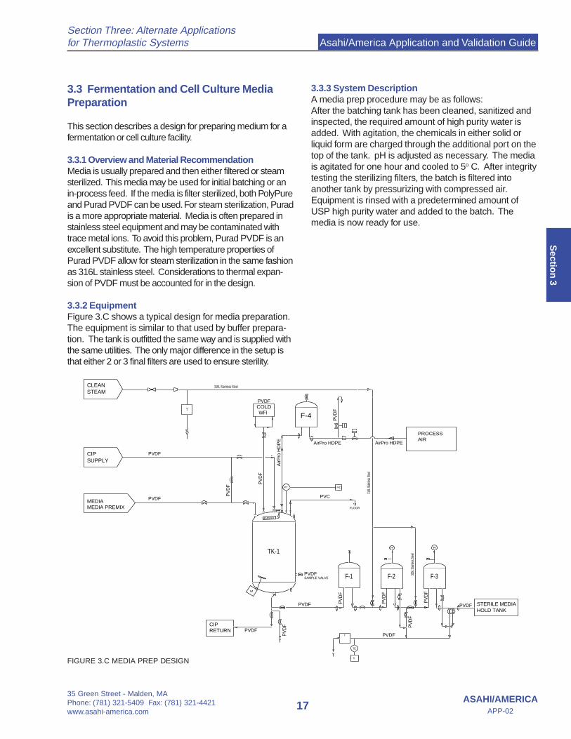
3.3 Fermentation and Cell Culture MediaPreparation
This section describes a design for preparing medium for afermentation or cell culture facility.
3.3.1 Overview and Material RecommendationMedia is usually prepared and then either filtered or steamsterilized. This media may be used for initial batching or anin-process feed. If the media is filter sterilized, both PolyPureand Purad PVDF can be used. For steam sterilization, Puradis a more appropriate material. Media is often prepared instainless steel equipment and may be contaminated withtrace metal ions. To avoid this problem, Purad PVDF is anexcellent substitute. The high temperature properties ofPurad PVDF allow for steam sterilization in the same fashionas 316L stainless steel. Considerations to thermal expan-sion of PVDF must be accounted for in the design.
3.3.2 EquipmentFigure 3.C shows a typical design for media preparation.The equipment is similar to that used by buffer prepara-tion. The tank is outfitted the same way and is supplied withthe same utilities. The only major difference in the setup isthat either 2 or 3 final filters are used to ensure sterility.
3.3.3 System DescriptionA media prep procedure may be as follows:After the batching tank has been cleaned, sanitized andinspected, the required amount of high purity water isadded. With agitation, the chemicals in either solid orliquid form are charged through the additional port on thetop of the tank. pH is adjusted as necessary. The mediais agitated for one hour and cooled to 5o C. After integritytesting the sterilizing filters, the batch is filtered intoanother tank by pressurizing with compressed air.Equipment is rinsed with a predetermined amount ofUSP high purity water and added to the batch. Themedia is now ready for use.
FIGURE 3.C MEDIA PREP DESIGN
T
CIP RETURN
COLDWFI
STERILE MEDIA HOLD TANK
TK-1
F-1 F-2 F-3
F-4
PROCESSAIR
M
SAMPLE VALVE
FLOOR
PT PIC
T
TI
TE
MANWAY
PI PI
316L Stainless Steel
316L
Stain
less S
teel
316L
Stain
less S
teel
PVDF
PVDF
PV
DF
PVDF
PV
DF
PVC
PV
DF
AirPro HDPE
PVDF
PVDF
PVDF
PV
DF
PV
DF
PV
DF
PVDF
PV
DF
PVDF
PV
DF
MEDIAMEDIA PREMIX
CIP SUPPLY
CLEANSTEAM
AirPro HDPE
AirP
ro H
DP
E

Asahi/America Application and Validation Guide
35 Green Street - Malden, MAPhone: (781) 321-5409 Fax: (781) 321-4421
www.asahi-america.com18
Section Three: Alternate Applicationsfor Thermoplastic Systems
ASAHI/AMERICAAPP-02
Sec
tio
n 3
3.4 Clean-in-Place Systems
3.4.1 OverviewClean-in-Place (CIP) Systems are commonly used inpharmaceutical and biopharmaceutical facilities. Figure3.D shows a typical two tank CIP system. Similar designsare found with single and three tank variations.
3.4.2 MaterialsAlthough CIP systems are frequently constructed witheither 304 or 316 stainless steel, the use of PVDF orpolypropylene (pigmented or unpigmented) can be aviable alternate. Advantages include: reduced installationcosts, corrosion resistance, less insulation needs (for hotsystems), reduced or eliminated borescoping require-ments and no passivation.
Thermoplastic materials will out perform metal systemsexposed to caustics, acids or chlorinated medias.However, no one single plastic material is ideal for allmedia. It is important to consult Asahi/America’sengineering department for a specific recommendation.
Polypropylene is ideal for high pH medias and in somecases strong acids. Polypropylene is not recommendedfor chlorinated service or extremely high acid concentra-tions.
PVDF is ideal for aggressive acids and many chlorinatedservices. However, it is not recommended for high pHlevels.
E-CTFE, known as Halar , is an excellent plastic for abroad range of aggressive chemicals. In particular,E-CTFE is excellent in Sodium Hypochlorite applications.
For all systems, factors such as thermal expansion andUV exposure must be considered.
3.4.3 System DescriptionA CIP system is a packaged unit of integrated compo-nents.
- Controlled Rinsing: Controlled temperature rinsingwhich involves partial cleaning without the usage ofchemicals.
Flow Control ValveCIP Piping
WaterSupply
WaterSupply
PurifiedWater
PurifiedWater
WaterRecircorSolutionRecoveryTank
WaterorRecircTank
Level Level
VortexFlow Meter
Pressure
Temperature
SteamSupply
Steam
T
Heat Exchanger(as needed)
Cleaning ChemicalFeed Loop
Chemical
Alkaline Acidic
CIP Supply Pump
PumpCaseDrainValve
ReturnFlow Probe
Temperature
Conductivity
DrainValve
CIP ReturnPiping
Air Relief Valve
TankInlet
TankOutlet
To FurtherProcessing
Process Vessel(to be cleaned)
FIGURE 3.D TWO TANK CIP SYSTEM (Note: Either Proline PP or Purad PVDF can be used as piping material depending upon cleaningagent used. Proline PP is excellent for most caustic agents)
Asahi/America Application and Validation Guide
35 Green Street - Malden, MAPhone: (781) 321-5409 Fax: (781) 321-4421www.asahi-america.com
19ASAHI/AMERICA
APP-02
Section Three: Alternate Applicationsfor Thermoplastic Systems
Sectio
n 3
- Controlled temperature washing automatically controlsthe system’s exposure to the cleaning agents and rinsesto insure consistent results. By controlling volume andpressure, sufficient turbulence is created to insureoptimum cleaning conditions.
- Controlled chemical concentrations results in effectivecleaning. Consistent and repeatable chemical dosage isessential from maximum effectiveness
- Final rinsing is usually performed with high purity water.It may be sent to drain or used as the first stage rinse ofthe next cycle.
CIP systems are used in many industries and now havebecome a standard for pharmaceutical andbiopharmaceutical applications.
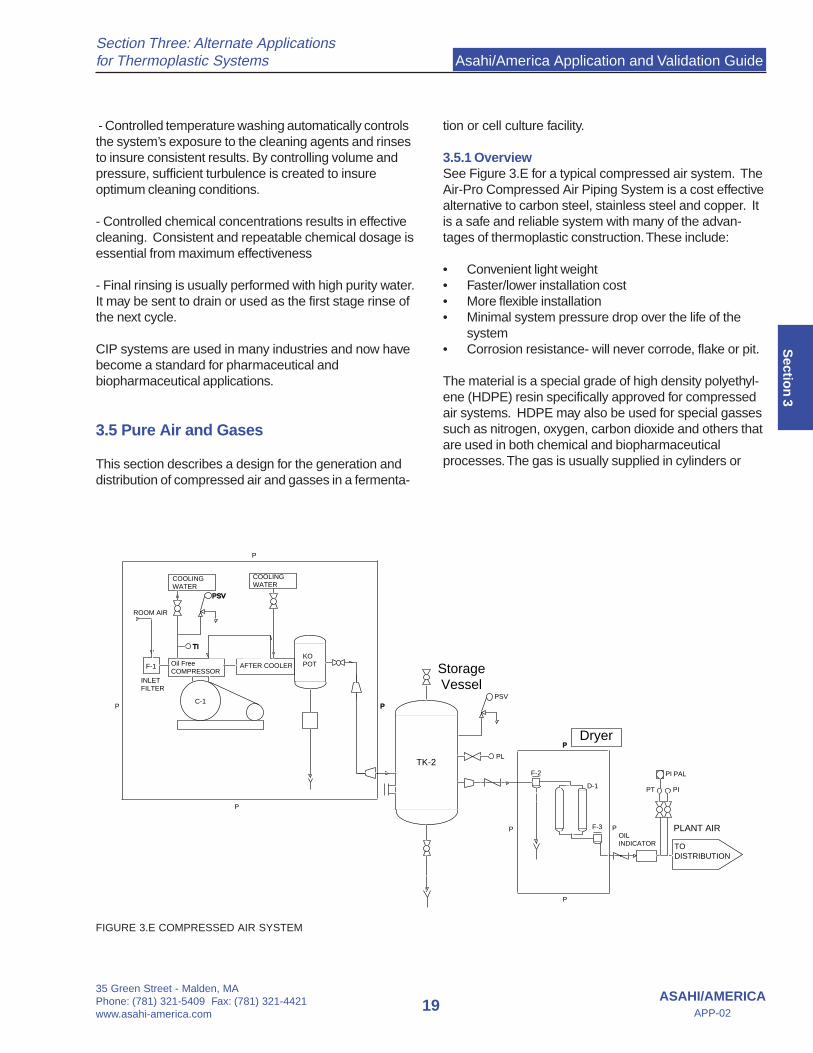
3.5 Pure Air and Gases
This section describes a design for the generation anddistribution of compressed air and gasses in a fermenta-
tion or cell culture facility.
3.5.1 OverviewSee Figure 3.E for a typical compressed air system. TheAir-Pro Compressed Air Piping System is a cost effectivealternative to carbon steel, stainless steel and copper. Itis a safe and reliable system with many of the advan-tages of thermoplastic construction. These include:
• Convenient light weight• Faster/lower installation cost• More flexible installation• Minimal system pressure drop over the life of the
system• Corrosion resistance- will never corrode, flake or pit.
The material is a special grade of high density polyethyl-ene (HDPE) resin specifically approved for compressedair systems. HDPE may also be used for special gassessuch as nitrogen, oxygen, carbon dioxide and others thatare used in both chemical and biopharmaceuticalprocesses. The gas is usually supplied in cylinders or
FIGURE 3.E COMPRESSED AIR SYSTEM
PL
KOPOTAFTER COOLER
INLETFILTER
ROOM AIR
COOLING WATER
COOLING WATER
PSVPSV
PSV
OILINDICATOR TO
DISTRIBUTION
PLANT AIR
PI PAL
PIPT
F-1 Oil FreeCOMPRESSOR
F-2
F-3
D-1
C-1
TK-2
P
P
P P
P
P
P
P
TITI
StorageVessel
Dryer

Asahi/America Application and Validation Guide
35 Green Street - Malden, MAPhone: (781) 321-5409 Fax: (781) 321-4421
www.asahi-america.com20
Section Three: Alternate Applicationsfor Thermoplastic Systems
ASAHI/AMERICAAPP-02
Sec
tio
n 3
tanks
3.5.2 ApplicationsThe following Systems are usually found in both pharma-ceutical and biopharmaceutical facilities:
• Compressed Air• Process• Instrument• Breathing• Nitrogen• Carbon Dioxide• Oxygen
Both process air and nitrogen are used for transfer offluids. Carbon dioxide is used in fermentation or cellculture for pH control. Oxygen and compressed air areused in fermentation and cell culture to supply dissolvedoxygen.
Although stainless steel with compression fittings areused, it is neither required nor cost effective. All of thesesystems may be constructed of thermoplastics. Thepiping systems should be readily cleanable from theoutside. Support spacing is an important design consid-eration.
3.5.3 GassesBulk storage of gasses using multiple cylinders or asingle large storage tank is the preferred method. Asegregated access controlled area should be locatedoutdoors adjacent to the building. A contract with a localprovider assures that there is always an adequatesupply.
3.5.4 Compressed AirOil free compressors are required. The system containsthe following components:• Inlet filter• One or two compressors• After cooler• Storage Tank• Air dryer (refrigerated or desiccant type - depending
on dryness required)• Final 0.2 micron filter
To assure required sterility at points of use, a final 0.2micron filter is usually recommended. A single com-pressed air system should be sized to provide instrumentair as well as emergency breathing air if required.
Consult the Asahi/America Piping Design Guide for theproper design and layout of a compressed air pipingsystem.
Asahi/America Application and Validation Guide
35 Green Street - Malden, MAPhone: (781) 321-5409 Fax: (781) 321-4421www.asahi-america.com
21ASAHI/AMERICA
APP-02
Section Four: Material Comparisons
Sectio
n 4
ID ID IDNominal
inchActualinch
Actualinch
Nominalinch
Actualinch
Nominalinch
Actualinch
½ 0.5 0.37
¾ 0.75 0.62 ½ 20 0.79 0.64 ½ 20 0.79 0.59
1 1 0.87 ¾ 25 0.98 0.83 ¾ 25 0.98 0.77
1 ¼ 1 32 1.26 1.07 1 32 1.26 1.02
1 ½ 1.5 1.37 1 ¼ 40 1.57 1.39 1 ¼ 40 1.57 1.3
2 2 1.87 1 ½ 50 1.97 1.74 1 ½ 50 1.97 1.61
2 ½ 2.5 2.37 2 63 2.48 2.24 2 63 2.48 2.02
3 3 2.87 2 ½ 75 2.95 2.66 2 ½ 75 2.95 2.41
Stainless Tube
Actualinch
Actualinch
OD OD OD
PolyPure and Proline PP, SDR11Purad PVDF, SDR21
Section FourMaterial Comparisons
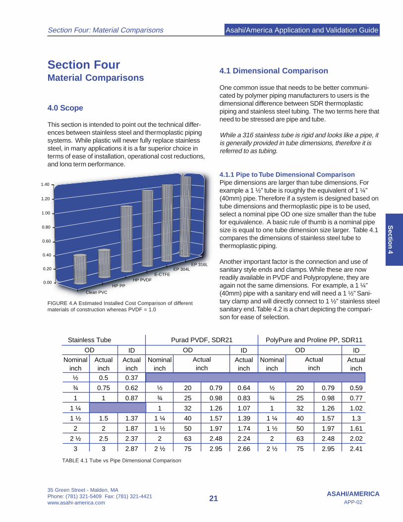
4.0 Scope
This section is intended to point out the technical differ-ences between stainless steel and thermoplastic pipingsystems. While plastic will never fully replace stainlesssteel, in many applications it is a far superior choice interms of ease of installation, operational cost reductions,and long term performance.
4.1 Dimensional Comparison
One common issue that needs to be better communi-cated by polymer piping manufacturers to users is thedimensional difference between SDR thermoplasticpiping and stainless steel tubing. The two terms here thatneed to be stressed are pipe and tube.
While a 316 stainless tube is rigid and looks like a pipe, itis generally provided in tube dimensions, therefore it isreferred to as tubing.
4.1.1 Pipe to Tube Dimensional ComparisonPipe dimensions are larger than tube dimensions. Forexample a 1 ½” tube is roughly the equivalent of 1 ¼”(40mm) pipe. Therefore if a system is designed based ontube dimensions and thermoplastic pipe is to be used,select a nominal pipe OD one size smaller than the tubefor equivalence. A basic rule of thumb is a nominal pipesize is equal to one tube dimension size larger. Table 4.1compares the dimensions of stainless steel tube tothermoplastic piping.
Another important factor is the connection and use ofsanitary style ends and clamps. While these are nowreadily available in PVDF and Polypropylene, they areagain not the same dimensions. For example, a 1 ¼”(40mm) pipe with a sanitary end will need a 1 ½” Sani-tary clamp and will directly connect to 1 ½” stainless steelsanitary end. Table 4.2 is a chart depicting the compari-son for ease of selection.
TABLE 4.1 Tube vs Pipe Dimensional Comparison
FIGURE 4.A Estimated Installed Cost Comparison of differentmaterials of construction whereas PVDF = 1.0
Clean PVC
HP PPHP PVDF
E-CTFEEP 304L
EP 316L
0.00
0.20
0.40
0.60
0.80
1.00
1.20
1.40

Asahi/America Application and Validation Guide
35 Green Street - Malden, MAPhone: (781) 321-5409 Fax: (781) 321-4421
www.asahi-america.com22
Section Four: Material Comparisons
ASAHI/AMERICAAPP-02
Sec
tio
n 4
Material RA Result
Purad PVDF (20mm - 90mm) 7.8 µ” max
EP 316L Stainless Steel 15-25 µ” average
MP 316L Stainless Steel 20-30 µ” average
4.2 Surface Finish Comparison
It is believed that the electropolished pipe is the smooth-est pipe available. Table 4.3 compares internal surfacefinish between PURAD PVDF, 316 electropolished (EP)and 316 mechanically polished (MP). The data is basedon manufacturer’s published data and not test results.From the chart it can be seen that comparable PVDFsystems provide a smoother surface finish as comparedto stainless steel. The Purad System is over 8%smoother than standard EP stainless steel and 30%smoother than most MP stainless steel.
Purad PVDF surfaces are continuously monitored duringproduction. In addition to production control, the QualityControl department conducts separate inspections ofsurface finish and other quality measures of each lot ofproduction.
Studies conducted by G. Husted of MicroTechnoResearch, Inc have compared the bioadhesion proper-ties of high performance thermoplastics (PVDF and E-CTFE) with that of high grades of EP and MP 316Lstainless steel. Test samples were continuously rinsed ata velocity of 3 feet per second with E-1 quality UPWstream.
Clamp Size
Nominal Actual (Nominal Tube)
½" 20mm ½" / ¾"
¾" 25mm 1"
1" 32mm 1 ½"
1 ¼" 40mm 1 ½"
1 ½" 50mm 2"
2" 63mm 2 ½"
Thermoplastic Pipe Size
Table 4.3 Surface Finish Comparison PVDF and 316L Stainless
At weekly intervals 3 randomly selected discs of each testmaterial [were] removed from the sampler, rinsed with a jetof double filtered UPW to remove non-firmly associatedcells, stained with acridine orange, then viewed withepifluorescent illumination at 1,2400X.”
The samples were examined and had their biocoloniza-tion levels directly counted. The results of which areshown on Table 4.4
From these tests, it is evident high performance thermo-plastics are more resistant to bioadhesion than highgrades of stainless steels.
In addition Purad PVDF, Proline PP and PolyPuresurface finishes are continuously monitored duringproduction. The roughness data is kept on record byproduction lot number. The data from this testing showingthe Ra values for each production lot can be madeavailable upon request.
4.3 Leachout Performance
While the surface profile is an important factor in terms ofreducing bioadhesion, the leachout from a pipe system ismore important to a systems overall purity level. A pipingsystem is the transporter of water to the point of use. Itsmaterial of construction and joining method directlyimpacts the ability to maintain strict levels of purity. Whilethe piping cannot positively influence water quality it canhave a dramatic negative effect on water quality.
Table 4.2 Sanitary Clamp Size Selection
Microbial Fouling of Materials in UPWAverage Direct Cell Count/cm2 (thousands) - Flow Velocity at 3 feet per second
Table 4.4 Bio-adhesion Comparison between MP 316L,EP 316L, PVDF and E-CTFE Materials
0
20
40
60
80
100
120
MP316L EP316L PVDF 1 PVDF 2 PVDF 3 E-CTFE 1 E-CTFE 2 E-CTFE 3 E-CTFE 4
Gre
ater
Tha
n 40
0,00
0
Asahi/America Application and Validation Guide
35 Green Street - Malden, MAPhone: (781) 321-5409 Fax: (781) 321-4421www.asahi-america.com
23ASAHI/AMERICA
APP-02
Section Four: Material Comparisons
Sectio
n 4
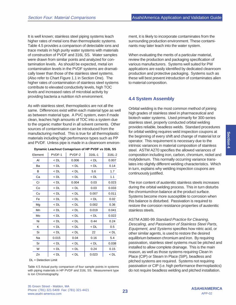
Element PVDF-1 PVDF-2 316L-1 316L-2
Al < DL 0.006 < DL 0.007
Ba < DL < DL < DL 0.14
B < DL < DL 5.6 1.7
Ca < DL < DL < DL 1.1
Cr < DL 0.004 0.03 0.023
Co < DL < DL 0.03 0.033
Cu < DL < DL 0.007 0.011
Fe < DL < DL < DL 0.02
Mg < DL < DL 0.002 0.36
Mn < DL < DL 0.019 0.041
Mo < DL < DL < DL 0.022
Ni < DL < DL 0.44 0.24
K < DL < DL < DL 0.5
Si < DL < DL 22 < DL
Na 0.015 0.04 0.16 5.4
Sr < DL < DL < DL 0.038
W < DL < DL 0.24 0.15
Zn < DL < DL 0.023 < DL
DL = Detection Limit
Dynamic Leachout Comaprison of HP PVDF vs 316L SS
It is well known; stainless steel piping systems leachhigher rates of metal ions than thermoplastic systems.Table 4.5 provides a comparison of detectable ions andtrace metals in high purity water systems with materialsof construction of PVDF and 316L SS. Water sampleswere drawn from similar points and analyzed for con-tamination levels. As should be expected, metal ioncontamination levels in the PVDF systems are dramati-cally lower than those of the stainless steel systems.(Also refer to Chart Figure 1.1 in Section One). Thehigher rates of contamination of stainless steel systemscontribute to elevated conductivity levels, high TOClevels and increased rates of microbial activity byproviding bacteria a nutrition rich environment.
As with stainless steel, thermoplastics are not all thesame. Differences exist within each material type as wellas between material type. A PVC system, even if madeclean, leaches high amounts of TOC into a system dueto the organic matter found in all solvent cements. Othersources of contamination can be introduced from themanufacturing method. This is true for all thermoplasticmaterials including high performance types such as PPand PVDF. Unless pipe is made in a cleanroom environ-
ment, it is likely to incorporate contaminates from thesurrounding production environment. These contami-nants may later leach into the water system.
When evaluating the merits of a particular material,review the production and packaging specification ofvarious manufacturers. Systems well suited for PWapplications are easily identified by dedicated cleanroomproduction and protective packaging. Systems such asthese will best prevent introduction of contaminates aliento material composition.
4.4 System Assembly
Orbital welding is the most common method of joininghigh grades of stainless steel in pharmaceutical andbiotech water systems. Used primarily for 300-seriesstainless steel, properly conducted orbital weldingprovides reliable, beadless welds. Standard proceduresfor orbital welding requires weld inspection coupons atthe beginning of every shift and change of material lot oroperator. This requirement is necessary due to theintrinsic variances in material composition of stainlesssteel. ASTM A270 specifies the allowed variances ofcomposition including iron, carbon, chromium, nickel andmolybdenum. This normally occurring variance trans-lates into slightly different welding characteristics. Whichin turn, explains why welding inspection coupons arecontinuously justified.
The iron content of austenitic stainless steels increasesduring the orbital welding process. This in turn disturbsthe chromium/iron balance at the product surface.Systems become more susceptible to corrosion whenthis balance is disturbed. Passivation is required torestore the corrosion resistance properties of austeniticstainless steels.
ASTM A380-99 Standard Practice for Cleaning,Descaling, and Passivation of Stainless Steel Parts,Equipment, and Systems specifies how nitric acid, orother similar agents, is used to restore the desiredequilibrium between chromium and iron. By requiringpassivation, stainless steel systems must be pitched andinstalled to allow complete drainage. This is the mainreason, as well as those systems requiring Clean InPlace (CIP) or Steam In Place (SIP), beadless andpitched systems are required. Systems not requiringpassivation or CIP (i.e. high performance thermoplastics)do not require beadless welding and pitched installation.
Table 4.5 Actual purity comparison of four sample points in systemswith piping materials in HP PVDF and 316L SS. Measurement typeis Ion Chromotography.
Asahi/America Application and Validation Guide
35 Green Street - Malden, MAPhone: (781) 321-5409 Fax: (781) 321-4421
www.asahi-america.com24
Section Four: Material Comparisons
ASAHI/AMERICAAPP-02
Sec
tio
n 4
Thermoplastics offer simplified welding techniques andinstallation. Both PVDF and PP are melt-processablepolymers. Systems are joined by a variety of thermal-fusion welding techniques. As mentioned, PVDF and PPresins are extremely pure and immensely consistentfrom lot to lot. This purity and consistency allows fordependable welding parameters, which translate intorepeatable and reliable welding techniques. Stainlesssteel welding concerns such as sulfur concentration,chromium depletion, condition of tungsten electrodes arenot issues for thermoplastics. The result is simplifiedwelding and installation practices with thermoplasticsystems.
One of the most common high-purity welding methodsfor high performance thermoplastics such as PVDF andPP is a non-contact method known as Infrared (IR)Fusion. IR Fusion is accomplished by bringing the pipecomponents into close proximity with a heating element.Direct contact with the heater is avoided in order tominimize the risk of material contamination. IR Fusionprovides superior weld results in terms of purity, reliabilityand speed of installation. This is evident by the semicon-ductor industries overwhelming preference for thismethod of joining, even when compared to variousbeadless systems.(Please refer to Section Seven for greater details on IR Fusion andother available joining techniques.)
Many pharmaceutical engineers shy away form IRFusion because of the presence of an internal bead. It isincorrectly assumed the bead presents an area formicrobial proliferation. If this were the case, semiconduc-tor water systems would have continuous problems withmicrobial levels. This is simply untrue as evident byactual installations. For example, one leading semicon-ductor manufacturer has warning levels of 2.5cfu/100mland action limits of 5cfu/100ml for their UPW distributedin IR fused PVDF piping (1). These levels are well belowthe cGMP action levels of 10cfu/100ml for WFI and10,000cfu/ml for PW!
Furthermore, leading process engineers have acknowl-edged the fact not all PW systems require pitchedinstallations with drainage capabilities. “[T]he intent of afully drainable system [in the context current GoodManufacturing Processes for Large Volume Parenterals(21CFR Part 212)] was to facilitate the draining ofcondensate after a system had been steam sterilized.The complete drain ability of ambient or chemicallysanitized piping systems that do not have the ability to besteamed is not required. Nor is it reasonable for many
water treatment operations, many of which do not havethe ability to be steamed, to be required to be drainedcompletely free of water” (2).
1. Lee, Ron; Patterson, Michael, Ph.D.; and Painter, John;“Semicondutors: The Efffect of Velocity on High-Purity Systems Rinse Upand Requalification”; Ultrapure Water Journal; March 2002; pg 41.2. Collentro, Andrew; “Pharmaceuticals: Practical Microbial ControlTechniques for Pharmaceutical Water Purification Systems”;Ultrapure Water Journel; March 2002; pg 56.
4.5 Rouging
Rouging is a ubiquitous and perhaps a misunderstoodphenomenon that unfortunately is associated with thepharmaceutical industry. Rouge is an unacceptablevisible evidence of water contamination by 316L stainlesssteel with corrosion by-products, primarily heavy metals.Regardless of cause, rouging is a serious issue, whichmust be dealt with in every stainless sanitary system.
The reason rouge is not well explained lies in part withthe ephemeral nature of the effect and its unusualassociation primarily with the pharmaceutical and dairyindustries. A review of the literature also reveals littlestudy of the matter. There is a lot of contradiction on thecauses and treatment. Metallurgists hold a part of thepuzzle, but they do not have experience with hot WFIsystems. Pharmaceutical engineers hold another key,but they may not have corrosion expertise. Passivationengineers have their take on the rouging problem, but arenot very helpful in preventing rouge, only treating it.
It is interesting to note the following two facts:
· Nitric acid passivates stainless steel, but does notdissolve ferrous or ferric oxides; therefore it does notremove rouge.· Acid cleaning removes rouge but does not passi-vate 316L stainless steel.
Stainless systems inherently require two timely andcostly operations not required in thermoplastic systems.
Nobody can convincingly explain the causes or methodsto prevent rouge in a stainless system. Having beensaid, water is truly the universal solvent. Therefore,stainless steel corrodes in high purity water. The metalscontent or rate of stainless steel corrosion can bedetermined by direct ICP/MS analysis of high puritywater for metals. Experience has documented lowerlevels of metal ionic contamination is found in ambient
Asahi/America Application and Validation Guide
35 Green Street - Malden, MAPhone: (781) 321-5409 Fax: (781) 321-4421www.asahi-america.com
25ASAHI/AMERICA
APP-02
Section Four: Material Comparisons
Sectio
n 4
temperature systems than comparable high temperaturesystems. In other words, stainless systems corrode androuge quicker in high temperature operation. Hightemperature systems may be effective in controllingmicrobial activity but contribute to the overall degradationof water quality.
The metal content in these water systems is evidence ofrouge and its contamination of the water. The heavymetal contamination by-product of rouge includes: Fe, Al,Ba, Cr, Cu, Co, Mn, Ni, Mo, W, Zn. For every corrosionsource point, often exhibited by a hard discoloration ofthe pipe surface, there can be a deposition including inextreme cases, visible particles carried in the water.Rouge may be a self-catalyzing reaction that will reoccursome time after treatment.
The surface area of 316L stainless steel in contact withUPW should be minimized to avoid rouge and its con-tamination affects. When compared to hot or steamcleaned systems, ambient systems reduce the speed inwhich rouging spreads its harmful effects. USP25guidelines now allow WFI quality water to be achievedthrough RO operation instead of traditional distillation.cGMPs also suggest 65°C is just as effective as 80°C incontrolling microbial activity. Under these guidelines, whyconsider water distribution through expensive andcorrosion susceptible stainless steel? High performancethermoplastics such as PP and PVDF can quicklybecome the obvious answer to rouge and its ubiquitousand unacceptable industry wide contamination issue.
4.4.1 Avoiding RougeStainless steel can not be completely avoided in highpurity water systems. In fact, stainless steel may bethe preferred material for certain applications. How-ever, the best method to avoid rouging is to limit theusage of stainless steel.
Stills- Stills can be a source of rouge and are oftenbadly corroded when examined. Do not worry aboutrouge from main boilers; it will not carry over in thesteam. The condenser and all wetted surfaces thereaf-ter should be 316L stainless steel or Thermoplasticwhere applicable.
Pumps – All pump impellers and wetted surfaces shouldbe 316L stainless steel, if not coated with high perfor-mance thermoplastic. Erosion due to pump cavitationwill exacerbate rouging episodes.
Storage tanks- Use lined storage tanks for ambienttemperature storage. Some stainless steel can beaccommodated, and a stainless storage tank alonemay be acceptable.
Piping – Ideally, piping material should be thermoplas-tic. Thermoplastic pipe, valves, fittings and measure-ment device will not rouge or corrode. In applicationsabsolutely requiring stainless steel, 316L should bespecified.
4.6 Bioadhesion Comparison & Control
The control of bacteria as a contaminant in productwater should be the primary concern in the design andutilization of high purity water systems for Life Sci-ences applications. It is only recently that scientistshave begun conceptualizing and treating bacteria notas discreet units, but as highly diverse, protected,complex communities, known as biofilm.
Understanding the formation, properties and behaviorof the biofilm is required to effectively deal withbacteria in Life Sciences’ water systems. This under-standing assists designers and operators in attackingthe core issues rather than the symptoms of bacterialaden water systems.
Biofilm Definitions- A thin layer of bacteria and organic matter that
occurs under the viscous boundary layer, at theinterface between the bulk water phase and solidsystem components such as piping, filters andresins. An immobilized cell thin-film bioreactor.1
- A complex and highly diversified community ofviable and nonviable microorganisms, their associ-ated glycocalyx, adsorbable organics, and en-trained particles.2
Bacteria cells are present, to some degree, in alldistribution piping systems and adhere to essentiallyall wetted surfaces. Furthermore, “(b)iofilms formexpected densities after 2 weeks on all wetted sur-faces, regardless of flow velocity.”3 The presence ofbiofilms in high purity water piping, to some degree, isunavoidable. Once understood, the issue then be-comes how to best minimize and limit biofilm and itadverse effects.

Asahi/America Application and Validation Guide
35 Green Street - Malden, MAPhone: (781) 321-5409 Fax: (781) 321-4421
www.asahi-america.com26
Section Four: Material Comparisons
ASAHI/AMERICAAPP-02
Sec
tio
n 4
4.6.1 Methods of Controlling Biofilm
HeatHeat has been proven to be an effective means ofcontrolling overall system biocolonization levels. Hotsystems are typically operated at 80ºC. Purad PVDFsystems can easily handle systems designed tooperate and sanitize at this temperature.
Recently, ISPE’s Baseline Guide, Volume IV, “Water andStream Systems”, Jan 02, has recognized 65ºC as anequally effective temperature as 80ºC. PolyPure andProline PP Systems can and should be consideredunder these circumstances.
In either case, PVDF and PP are excellent thermalinsulators. Hot piping systems (up to 80ºC+) con-structed of PVDF and PP do not require externalinsulation for maintaining critical, hot temperatures orfor protection from injury resulting from burns.
However, those who use heat sanitization for ambienttemperature systems such as carbon beds, RO mem-branes, distribution loops, etc. should be aware thatheat sanitization does not remove biofilm, regardless ofmaterial of construction. In such systems, failure toremove a biofilm may lead to its re-colonization andgrowth even faster than with bare pipe. The old biofilmserves as an excellent capture and attachment site withnutrients at hand.
In addition, hot stainless steel water Life Sciencesapplications have become less attractive due to safety,cost and quality considerations (i.e. rouging – Pleaserefer to Section 4.5 for discussion on rouging) and themove towards in-line mixing and the preponderance ofambient temperature applications. In addition, mostpoints of use must be cooled prior to supply. This canadd to sanitation concerns for improperly operatedsystems.
VelocityPowell’s work showed the average velocity to removebiofilm from electropolished pipe is 12 ft/sec. This istwo times (2X) the average maximum velocity of waterin distribution piping which results in an unacceptablepressure drop. The minimum thickness of the laminarsub layer for cold water is about 0.1 – 0.2 mm.8 Evenmature biofilm with films 5 µm thick would require 5layers to begin to protrude into the turbulent flow at 8.6ft/sec. As such, high velocity of water in distribution hasbeen shown to have little or no effect in the control ofmicrobiology and biofilm formation.3, 6 In fact, exces-sive flow velocities may actually accelerate biofilmgrowth.3
The primary source of planktonic (free-floating) Microor-ganisms in the bulk phase of the high purity water isdetachment of cells from the interfacial biofilm.2, 4 Asbiofilm shearing adds to the overall nutrient levels ofwater systems, the sheared cells are quickly replacedwith new levels of biofilm feeding in the relativelynutritious environment. This in turn leads to new layersof biofilm shearing into the flow stream. A troublesomecycle is now possible.
Limiting their growth in the high purity environment maybest control biofilms and system bacteria levels. Inhigh purity environments, cell proliferation in the biofilmis severely inhibited by a combination of colonization orinoculation prevention and nutrient deprivation.
Inoculation PreventionPreventing inoculation of a piping system is a functionof the water system design, not the distribution pipingdesign. The water system design must limit andprevent both viable and nonviable organisms fromproceeding downstream. It is a function of filtration withRO being one of the more effective means. Thisprevents seeding of a potential biofilm by colonizingbacteria and perhaps more importantly prevents liveand dead organisms from providing a nutrient source todownstream biofilms.
Nutrient DeprivationIn extreme nutrient deficient environments, bacteria willnot attach to surfaces. If they do not attach, theycannot form biofilm. – Costerton7
TOC control is essential to preventing biofilm prolifera-tion. Water systems should not operate with TOC over5ppb. Ideally the systems should run at < 0.5 ppb or500 ppt TOC. This is a far tighter control of TOC thanthe 500 ppb allowed by regulation in Life Scienceswater systems. Water systems with more than 50 ppbTOC are decidedly nutrient rich, and bacteria problemscan be expected.
Multiple nutrient restrictions (phosphorous, nitrogen,potassium) appear to limit growth.4 Water systemsshould target detectable elements at no more than 10ppt. Borone should be the exception, which, if required,must be dealt with separately.8 Standard designed RO/DI water systems are capable of routinely and continu-ously providing water of this quality. As shown on chart1.A on page two of this guide, thermoplastic pipingsystems typically operate at extremely lower rates ofion contamination than 316L systems, thus, avoidingcontribution to nutrition level required for the prolifera-tion of biofilm and bacteria laden systems. This is thebasis of biofilm control in the semiconductor industrywhere routine decontaminations and sanitation cycles
Asahi/America Application and Validation Guide
35 Green Street - Malden, MAPhone: (781) 321-5409 Fax: (781) 321-4421www.asahi-america.com
27ASAHI/AMERICA
APP-02
Section Four: Material Comparisons
Sectio
n 4
are avoided, as the procedures themselves are consid-ered a source of contamination. Additionally, it requiresdowntime that is neither available nor appreciated.Although semiconductor water requirements are differ-ent than those required for Life Sciences, high qualitywater with controlled biocolonization and endotoxinlevels are issues for both industries.
Materials of ConstructionThermoplastics are the preferred choice for the materi-als utilized in UPW systems and distribution pipingwhere water quality is the primary concern.
The product water from Life Science water systemsutilizing 316L piping, always demonstrate a distinctmetal ion signature, mirroring the composition of the316L distribution piping. Trace metals for 64 elementsas measured by ICP/MS are typically negative for highpurity thermoplastic water systems to parts per trillion(ppt) levels.8
It is clear that 316L stainless steel supports the attach-ment and apparently promotes the growth of biofilmwhen compared side by side with thermoplastics in aseries of tests. Gray states that stainless steel wasgenerally concluded to allow more extensive biofilmgrowth than plastics.9, 6 Husted found consistently lowermicrobial cell densities and biofouling, per unit area, arenoted for thermoplastics when compared to stainlesssteel.9 (See Section 4.2 for more details).
Surface finish alone does not appear to explain thedisparity between 316L stainless steel and Thermoplas-tic piping systems. The average wall smoothness forPolypropylene is not as good as mechanical finished316L stainless steel, yet experience indicates bacteriacounts in the bulk water phase for Polypropylene is verysimilar to other thermoplastics reported in the data.This may indicate the biofouling is reduced for Polypro-pylene despite a rougher average pipe wall finish.Further investigation is ongoing.
As mentioned above, one possible explanation may bethe metals in 316L provide a source of scarce limitingnutrients that are definitely not present in either PVDFor PP thermoplastic piping systems. However, thermo-plastics such as PVC should be avoided for the sol-vents required for system joining contribute to contami-nation concerns and system TOC levels. The fact thatPVDF may be employed at 65°C to 80°C and can besteam sanitized could make it an attractive option toreplace stainless steel in hot WFI applications and isbeing utilized more frequently.
There is no correlation between the presence of biofilmand the water quality delivered to Points of Use.7 Byinhibiting biofilm growth, the scant biofilm that may bepresent is left virtually irreversibly attached to thesubstrate (pipe surface) in the laminar sub layer where itis unable to be sloughed into the bulk flow. This allowsthe Semiconductor Industry to achieve total bacteriacounts (dead and alive) of less than 10 cells/liter.
4.6.2 ConclusionIn conclusion, thermoplastic piping systems should bespecified for exceptionally high quality water systemsfor the following reasons:
- 316L systems have been shown to be moresusceptible than PVDF to excessive biofilmformation.
- Hot water systems, if desired, are compatiblewith thermoplastic systems and do not experi-ence accelerated corrosion as with stainlesssystems.
- High performance thermoplastics do notcontribute to the nutrition (ion contamination)levels of water systems.
The key to controlling microbiology in high purity watersystems is maintaining exceptionally high water quality.Operating higher quality systems than mandated byUSP specifications should not be expensive. The useof very low TOC water (< 10 ppb TOC recommended)and thermoplastic distribution piping is conducive tocontrol microbiology via nutrient deprivation.
The Semiconductor/Thermoplastic approach to higherwater quality is proven effective and reliable and resultsin considerable cost savings in:
- Cost of Installation and Maintenance- No boriscoping, passivation or de-rouging
requirements- No hot water utilities infrastructure and opera-
tional costs
The Semiconductor Industry routinely operates ambientDI water systems with less than one cfu/ liter microbiol-ogy levels without routine sanitizations being required.The effective and proven practices of biofilm control inthis industry, of which thermoplastic piping systems is amajor factor, should be considered as applicable and acGMP for Life Sciences. Regardless of industry, lowbacteria counts and high quality water systems areabsolutely required.
Asahi/America Application and Validation Guide
35 Green Street - Malden, MAPhone: (781) 321-5409 Fax: (781) 321-4421
www.asahi-america.com28
Section Four: Material Comparisons
ASAHI/AMERICAAPP-02
Sec
tio
n 4
Section 4.6 Bibliography
1. Costerton, J.W. and Stewart, Philip S.; “BattlingBiofilm”; Scientific American; (July, 2001)
2. Patterson MK, Husted G. Rutkowski , et al.,“Isolation, Identification, and Microscopic Properties ofBiofilms in High-Purity Water distribution systems,”presented to the UltraPure Water Conference, SantaClare, CA. November 1990 and published in UltraPureWater Journal, 8(4):18-24, 1991
3 Martyak, J.E., Carmody J.E., and Husted G.R.;“Characterizing Biofilm Growth in Deionized UltraPureWater Piping Systems”, MicroContamination; 11(1) pp39-44 (January 1993)
4. Husted G. Rutkowski AA Couture A, “Responseof Oligotrophic Biofilm Bacteria in High Purity WaterSystems to Stepwise Nutrient Supplementation”,UltraPure Water Journal September 1994
5. “Battling Biofilm”; Scientific American; 7/2001
6. Gray, G.; “Recirculation Velocities in WFI DistributionSystems”; Pharmaceutical Engineering; Volume 17, #6,Nov/Dec 1997
7. Riedewald, F.; “Biofilms in Pharmaceutical Waters”;Pharmaceutical Engineering; Volume 17, #6, Nov/Dec1997
8. With the exception of very low levels of boron, whichcan often be detected in high purity water systemsregardless of design. Boron is typically the first ion tobreakthrough a water system.
9. Husted, G.; “ Evaluation of HALAR ECTFE for Sur-face Properties and Biofilm Formation in UltrapureWater Service”; Micro Techno Research; Hinesburg, VT,printed by Ausimont, USA (July 11, 1996)

Asahi/America Application and Validation Guide
35 Green Street - Malden, MAPhone: (781) 321-5409 Fax: (781) 321-4421www.asahi-america.com
29ASAHI/AMERICA
APP-02
Section Five: Validation Plan
Sectio
n 5
Section FiveValidation Plan andSample Validation Protocals
5.0 Generic Validation Plan
Prior to writing and building a validation plan, the es-sence of validation must be understood. The accepteddefinition of validation by the FDA is:
Documented evidence which provides a high degree ofassurance that a specific process will consistentlyproduce a product meeting its predetermined specifica-tions and quality attributes.
Note the underlined words. The documented evidence isprepared with the following industry protocols:
Installation Qualification (IQ)Documented verification that the equipment or systemhas been installed according to plans and specifications.All the pertinent information is assembled with thisdocument.
The IQ should be written at the conception of a projectand followed throughout the installation. In many cases itis written as an after thought to comply with regulations.Asahi/America provides the guideline for the IQ to makethe document useful to a project.
Operational Qualification (OQ)Verification that the system operates according to thedesign drawings and specifications. Failure modes andalarms are confirmed.
Process Qualification (PQ)Confirmation that the system will produce the product ormaterial as intended. Various operating configurationsmay require simulation. Analytical procedures must alsobe validated and the final test results complete thevalidation report.
The final document is a summary report which discussesthe validation and determines that all acceptance criteriahave been met.
It is extremely important to properly plan the validation ofthe system that is being installed. The plan becomes thebasis of the entire activity and establishes the followingcomponents:
1. Scope
2. Facility or Process Description
3. Systems and Equipment to be Validated
4. Responsibilities:Protocol PreparationProtocol Execution
5. Acceptance Criteria
6. Protoc0l Format
7. Reference Procedures:Standard Operating Procedures (SOP)Material Receiving ProceduresInspection ProceduresCalibration Procedures
8. Validation Schedule
9. Manpower Requirements
10. Change Control Procedures
11. Re-Validation Requirements
12. AppendicesRoom Classification and PressurizationDrawingsPersonnel and Material Flow DiagramProcess Flow ChartsDiscussion
Not all of the above items may be needed for a systemwhich is part of an overall facility project. The two mostimportant documents in the plan and the subsequentprotocols are a system description and a detailedprocess and instrumentation drawing. These should beprepared as soon as the design has been established.

Asahi/America Application and Validation Guide
35 Green Street - Malden, MAPhone: (781) 321-5409 Fax: (781) 321-4421www.asahi-america.com
33ASAHI/AMERICA
APP-02
Section Six: Materials and Systems Overview
Sectio
n 6
Section SixMaterials andSystems Overview
Material Max. Operating Ranges of ApplicationTemperature
PVDF 284 °F / 140 °C piping:- Cold and hot UPW distribution- Polishing system -Cleanroom loop system- Hook up system- Reclaim system- Drain / waste system- CIP Chemical distribution
E-CTFE 300 °F / 150 °C semifinished products:- Lining of UPW storage tanks- Lining of chemical storage tanks- Tank construction- Apparatus- Machined components
PolyPure 204 °F / 95 °C piping:Proline PP -Cold and hot UPW distribution
- Reclaim system- Drain / waste system- Reclaim system- CIP Chemical Distribution- Ventilation systems (Duct)
PVC 140 °F / 60 °C piping:-Cold UPW feedwater- Drain / waste system- Limited Reclaim system- Ventilation systems (Duct)
CPVC 195 °F / 90 °C piping:-Cold and hot UPW feedwater- Limited Reclaim system- Drain / waste system- Hot Acid Waste- Ventilation systems (Duct)
Thermoplastic Application Range
6.0 Materials Introduction
This section is devoted to the discussion of thermoplas-tics and their properties as they pertain to pharmaceuti-cal applications. References to polypropylene andPVDF are valid for Proline PP, PolyPure PP and PuradPVDF systems as offered by Asahi/America. Discus-sions of PVC and CPVC are relevant to our broad line ofvalving products, as well as a general guide for pipingsystems constructed of these materials
PVDF (Polyvinylidene Fluoride)This high molecular weight fluorocarbon has superiorabrasion resistance, dielectric properties and mechanicalstrength. These characteristics are maintained over atemperature range of -40 °F (-40 °C) to 284 °F (140 °C).In piping systems, PVDF is best suited for systemsoperating from 14 °F (-10 °C) to 250 °F (121 °C). PVDFis highly resistant to wet or dry chlorine, bromine andother halogens, most strong acids, aliphatics, aromatics,alcohols and chlorinated solvents. Because of its ex-tremely low amounts of extractables, PVDF is widelyused in the transport of ultra pure water for the semicon-ductor and pharmaceutical industries.
Asahi/America offers the Purad PVDF System for highpurity applications. Purad is ideal for Pure Water andWater for Injection service. It is available in sizes 20mmto 315mm (1/2” to 12”) with a wide assortment of fittings,valves and flowmeters.
E-CTFE (Ethylene Tetrafluoroethylene)E-CTFE fluoropolymer is commonly known by its tradename HALAR . E-CTFE is essential a 1:1 alternatingcopolymer of ethylene and CTFE (chlorotrifluoro-ethylene). It contains about 80% CTFE, one of the mostchemically resistant building blocks that can be used tomake a polymer. However, CTFE homopolymers aredifficult to fabricate, extrude or mold. By the copolymer-ization with ethylene, E-CTFE displays much of thechemical resistance of CTFE with the ease of process-ing. It provides excellent chemical resistance, handlingapplications that almost all other materials can not. Inparticular, E-CTFE demonstrates effective handling offuming acids and chlorinated bases.
It is the best material for handling high concentrations ofsodium hypochlorite. Additionally, E-CTFE has goodelectrical properties, and a broad-use temperature rangefrom cryogenic to 300°F (150° C). E-CTFE is a toughmaterial with excellent impact strength over its broad-usetemperature range. E-CTFE also maintains usefulproperties on exposure to cobalt 60 radiation at dosagesof 200 megarands. It is one of the best fluoropolymersfor abrasion resistance.
Ultra Proline Halar Systems is Asahi/America’s E-CTFEPiping System. Ultra Proline Systems are available insizes between 32mm and 110mm (1” and 4”) with abasic assortment of fittings and diaphragm valves. UltraProline Systems should be considered for aggressiveCIP applications such as high concentrations of sodiumhypochlorite, which have traditionally been difficult forother materials to handle.
HALAR is a registered trademark of Solvay Polymers
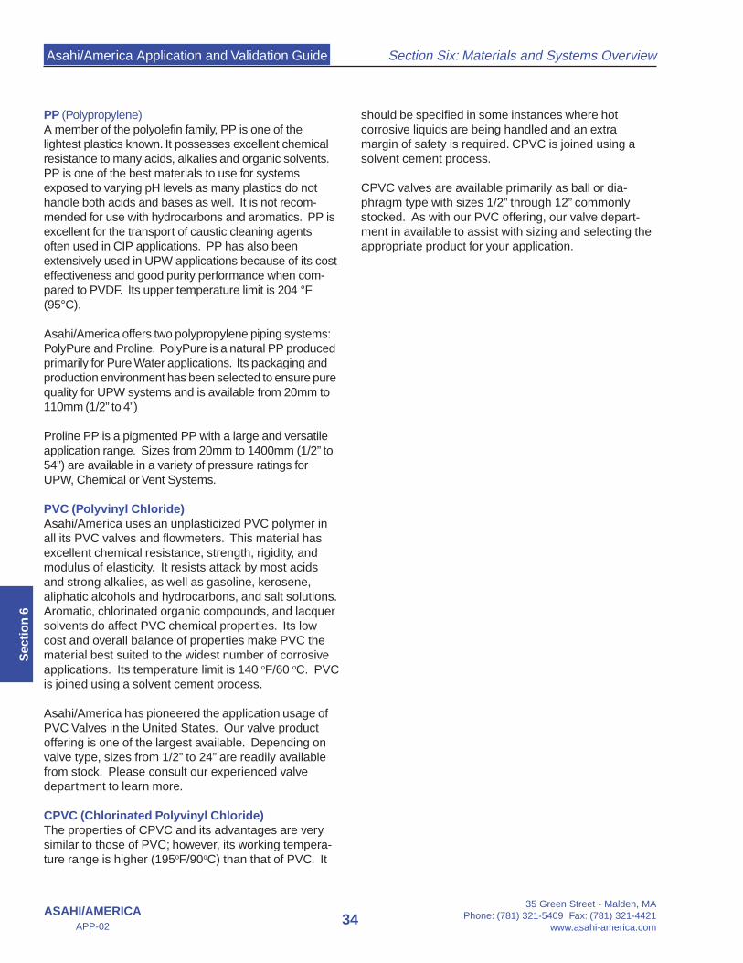
Asahi/America Application and Validation Guide
35 Green Street - Malden, MAPhone: (781) 321-5409 Fax: (781) 321-4421
www.asahi-america.com34
Section Six: Materials and Systems Overview
ASAHI/AMERICAAPP-02
Sec
tio
n 6
PP (Polypropylene)A member of the polyolefin family, PP is one of thelightest plastics known. It possesses excellent chemicalresistance to many acids, alkalies and organic solvents.PP is one of the best materials to use for systemsexposed to varying pH levels as many plastics do nothandle both acids and bases as well. It is not recom-mended for use with hydrocarbons and aromatics. PP isexcellent for the transport of caustic cleaning agentsoften used in CIP applications. PP has also beenextensively used in UPW applications because of its costeffectiveness and good purity performance when com-pared to PVDF. Its upper temperature limit is 204 °F(95°C).
Asahi/America offers two polypropylene piping systems:PolyPure and Proline. PolyPure is a natural PP producedprimarily for Pure Water applications. Its packaging andproduction environment has been selected to ensure purequality for UPW systems and is available from 20mm to110mm (1/2” to 4”)
Proline PP is a pigmented PP with a large and versatileapplication range. Sizes from 20mm to 1400mm (1/2” to54”) are available in a variety of pressure ratings forUPW, Chemical or Vent Systems.
PVC (Polyvinyl Chloride)Asahi/America uses an unplasticized PVC polymer inall its PVC valves and flowmeters. This material hasexcellent chemical resistance, strength, rigidity, andmodulus of elasticity. It resists attack by most acidsand strong alkalies, as well as gasoline, kerosene,aliphatic alcohols and hydrocarbons, and salt solutions.Aromatic, chlorinated organic compounds, and lacquersolvents do affect PVC chemical properties. Its lowcost and overall balance of properties make PVC thematerial best suited to the widest number of corrosiveapplications. Its temperature limit is 140 oF/60 oC. PVCis joined using a solvent cement process.
Asahi/America has pioneered the application usage ofPVC Valves in the United States. Our valve productoffering is one of the largest available. Depending onvalve type, sizes from 1/2” to 24” are readily availablefrom stock. Please consult our experienced valvedepartment to learn more.
CPVC (Chlorinated Polyvinyl Chloride)The properties of CPVC and its advantages are verysimilar to those of PVC; however, its working tempera-ture range is higher (195oF/90oC) than that of PVC. It
should be specified in some instances where hotcorrosive liquids are being handled and an extramargin of safety is required. CPVC is joined using asolvent cement process.
CPVC valves are available primarily as ball or dia-phragm type with sizes 1/2” through 12” commonlystocked. As with our PVC offering, our valve depart-ment in available to assist with sizing and selecting theappropriate product for your application.
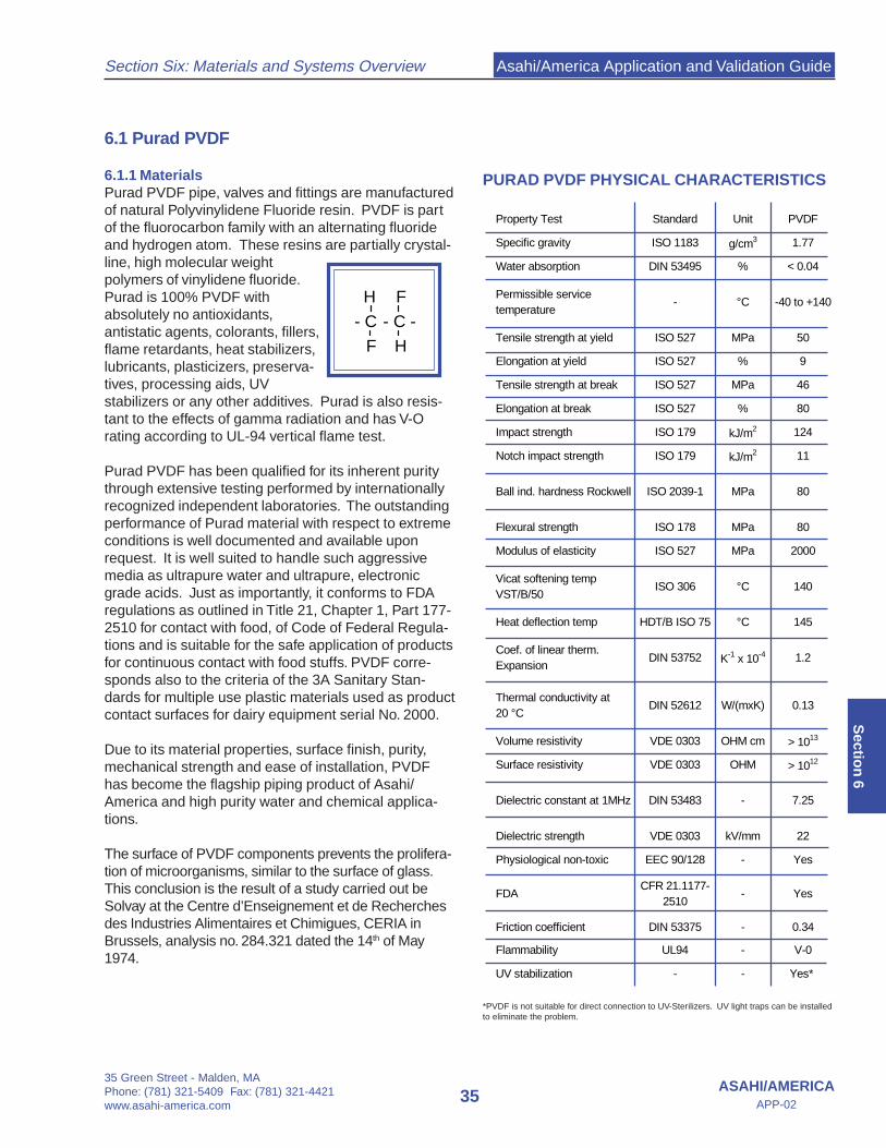
Asahi/America Application and Validation Guide
35 Green Street - Malden, MAPhone: (781) 321-5409 Fax: (781) 321-4421www.asahi-america.com
35ASAHI/AMERICA
APP-02
Section Six: Materials and Systems Overview
Sectio
n 6
Property Test Standard Unit PVDF
Specific gravity ISO 1183 g/cm3 1.77
Water absorption DIN 53495 % < 0.04
Permissible service temperature
- °C -40 to +140
Tensile strength at yield ISO 527 MPa 50
Elongation at yield ISO 527 % 9
Tensile strength at break ISO 527 MPa 46
Elongation at break ISO 527 % 80
Impact strength ISO 179 kJ/m2 124
Notch impact strength ISO 179 kJ/m2 11
Ball ind. hardness Rockwell ISO 2039-1 MPa 80
Flexural strength ISO 178 MPa 80
Modulus of elasticity ISO 527 MPa 2000
Vicat softening tempVST/B/50
ISO 306 °C 140
Heat deflection temp HDT/B ISO 75 °C 145
Coef. of linear therm. Expansion
DIN 53752 K-1 x 10⁻⁴ 1.2
Thermal conductivity at20 °C
DIN 52612 W/(mxK) 0.13
Volume resistivity VDE 0303 OHM cm > 1013
Surface resistivity VDE 0303 OHM > 1012
Dielectric constant at 1MHz DIN 53483 - 7.25
Dielectric strength VDE 0303 kV/mm 22
Physiological non-toxic EEC 90/128 - Yes
FDACFR 21.1177-
2510- Yes
Friction coefficient DIN 53375 - 0.34
Flammability UL94 - V-0
UV stabilization - - Yes*
6.1 Purad PVDF
6.1.1 MaterialsPurad PVDF pipe, valves and fittings are manufacturedof natural Polyvinylidene Fluoride resin. PVDF is partof the fluorocarbon family with an alternating fluorideand hydrogen atom. These resins are partially crystal-line, high molecular weightpolymers of vinylidene fluoride.Purad is 100% PVDF withabsolutely no antioxidants,antistatic agents, colorants, fillers,flame retardants, heat stabilizers,lubricants, plasticizers, preserva-tives, processing aids, UVstabilizers or any other additives. Purad is also resis-tant to the effects of gamma radiation and has V-Orating according to UL-94 vertical flame test.
Purad PVDF has been qualified for its inherent puritythrough extensive testing performed by internationallyrecognized independent laboratories. The outstandingperformance of Purad material with respect to extremeconditions is well documented and available uponrequest. It is well suited to handle such aggressivemedia as ultrapure water and ultrapure, electronicgrade acids. Just as importantly, it conforms to FDAregulations as outlined in Title 21, Chapter 1, Part 177-2510 for contact with food, of Code of Federal Regula-tions and is suitable for the safe application of productsfor continuous contact with food stuffs. PVDF corre-sponds also to the criteria of the 3A Sanitary Stan-dards for multiple use plastic materials used as productcontact surfaces for dairy equipment serial No. 2000.
Due to its material properties, surface finish, purity,mechanical strength and ease of installation, PVDFhas become the flagship piping product of Asahi/America and high purity water and chemical applica-tions.
The surface of PVDF components prevents the prolifera-tion of microorganisms, similar to the surface of glass.This conclusion is the result of a study carried out beSolvay at the Centre d’Enseignement et de Recherchesdes Industries Alimentaires et Chimigues, CERIA inBrussels, analysis no. 284.321 dated the 14th of May1974.
H F
- C - C -
F H
PURAD PVDF PHYSICAL CHARACTERISTICS
*PVDF is not suitable for direct connection to UV-Sterilizers. UV light traps can be installedto eliminate the problem.
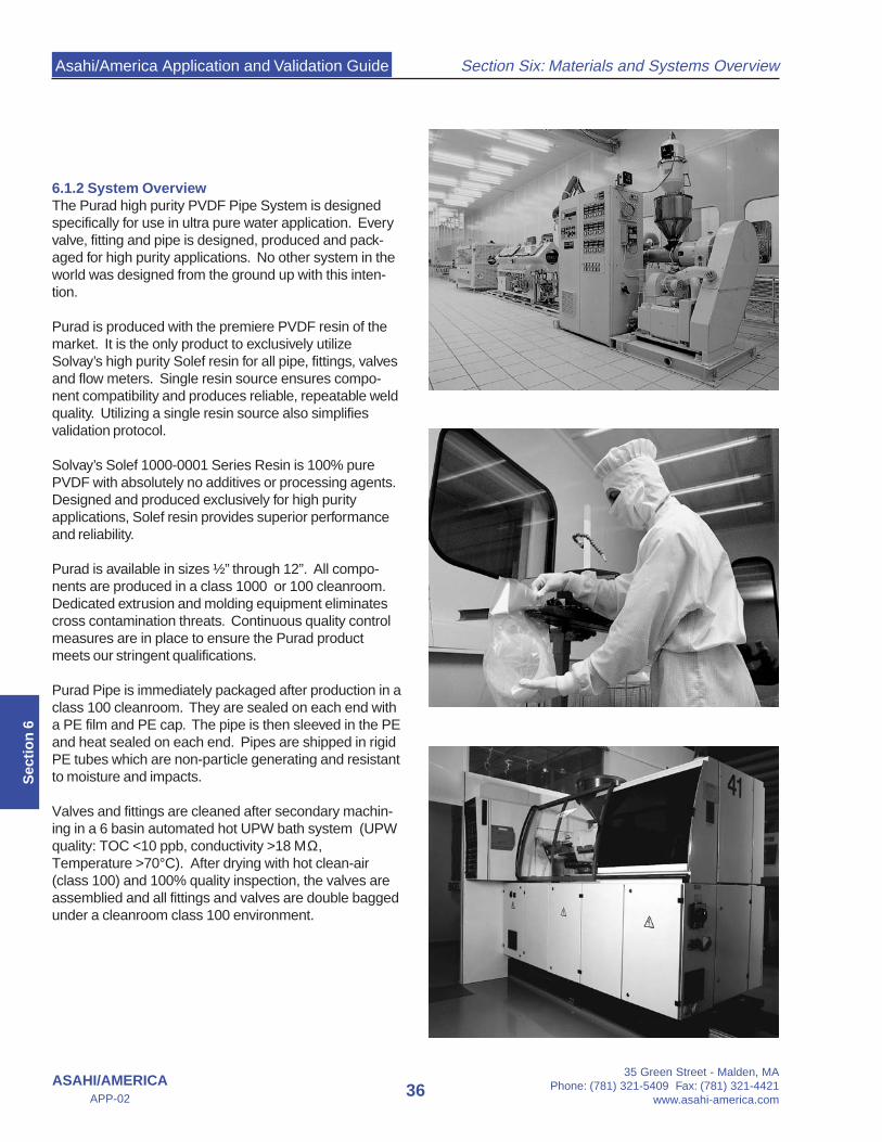
Asahi/America Application and Validation Guide
35 Green Street - Malden, MAPhone: (781) 321-5409 Fax: (781) 321-4421
www.asahi-america.com36
Section Six: Materials and Systems Overview
ASAHI/AMERICAAPP-02
Sec
tio
n 6
6.1.2 System OverviewThe Purad high purity PVDF Pipe System is designedspecifically for use in ultra pure water application. Everyvalve, fitting and pipe is designed, produced and pack-aged for high purity applications. No other system in theworld was designed from the ground up with this inten-tion.
Purad is produced with the premiere PVDF resin of themarket. It is the only product to exclusively utilizeSolvay’s high purity Solef resin for all pipe, fittings, valvesand flow meters. Single resin source ensures compo-nent compatibility and produces reliable, repeatable weldquality. Utilizing a single resin source also simplifiesvalidation protocol.
Solvay’s Solef 1000-0001 Series Resin is 100% purePVDF with absolutely no additives or processing agents.Designed and produced exclusively for high purityapplications, Solef resin provides superior performanceand reliability.
Purad is available in sizes ½” through 12”. All compo-nents are produced in a class 1000 or 100 cleanroom.Dedicated extrusion and molding equipment eliminatescross contamination threats. Continuous quality controlmeasures are in place to ensure the Purad productmeets our stringent qualifications.
Purad Pipe is immediately packaged after production in aclass 100 cleanroom. They are sealed on each end witha PE film and PE cap. The pipe is then sleeved in the PEand heat sealed on each end. Pipes are shipped in rigidPE tubes which are non-particle generating and resistantto moisture and impacts.
Valves and fittings are cleaned after secondary machin-ing in a 6 basin automated hot UPW bath system (UPWquality: TOC <10 ppb, conductivity >18 ΜΩ,Temperature >70°C). After drying with hot clean-air(class 100) and 100% quality inspection, the valves areassemblied and all fittings and valves are double baggedunder a cleanroom class 100 environment.

Asahi/America Application and Validation Guide
35 Green Street - Malden, MAPhone: (781) 321-5409 Fax: (781) 321-4421www.asahi-america.com
37ASAHI/AMERICA
APP-02
Section Six: Materials and Systems Overview
Sectio
n 6
The Purad PVDF system offers zero deadleg valves inover 35 size configurations from 20mm x 20mm to110mm x 63mm (½” x ½” to 4”x 2”). Specialty fittingssuch as instrument fittings allow for the proper installationof gauges and sample valves, completely eliminatingdead zones in a pipe system. Newly introduced needlevalves now provide an excellent method for drawing offlow volume samples.
System assembly can be conducted utilizing two ap-proved high purity methods. Beadless smooth surfacefusion is available from ½” to 2”. Non contact IR fusion isavailable from ½” to 10”. Both methods offer consider-able purity advantages over conventional methods. Forless critical applications, contact butt fusion and socketfusion are available. Please consult the installationsection of this manual and Asahi/America’s EngineeringDesign Guide for further information on joining tech-niques.
6.1.3 Surface FinishPurad PVDF is produced with extremely smooth surfacefinishes. Depending on size, finish quality tolerances areheld as tight as 7.5 µm Ra for both pipe and fittings. Theexcellent surface finish helps resist biofilm andbiocolonization. The smooth surface on our high puritycomponents are achieved by application of speciallydesigned and designated manufacturing equipment andtooling. Special materials and surface finishes of toolsused for injection moulding and extrusion have a signifi-cant influence upon the surface quality of the finishedproduct.
The surface quality is constantly monitored duringproduction of all high purity components. The surfaceroughness (Ra-values) and micropores are measured toensure system compliance. These tests are performedon a statistical basis and provide an excellent indicationof the quality of the manufacturing process. Additionally,independent labs and interferential microscopy are usedto measure quality in accordance with SEMATECH9201055 B (SEM).

Asahi/America Application and Validation Guide
35 Green Street - Malden, MAPhone: (781) 321-5409 Fax: (781) 321-4421
www.asahi-america.com38
Section Six: Materials and Systems Overview
ASAHI/AMERICAAPP-02
Sec
tio
n 6
6.1.4 Purad Pressure RatingAs with all thermoplastic materials, Purad’s pressurerating is derated as the operating temperature is in-creased. Purad has two available system ratingsdepending on the Standard Dimensional Ratio (SDR).SDR21 is rated for PN16/230psi services and SDR33has a PN10/150psi rating. To determine the rating basedon a system’s operating temperature use the table below.
6.1.4 Purad: The Pure AdvantageWhile many companies offer PVDF piping, only Asahi/America offers the Total System Approach. The PuradSystem is more than components, it is a highly engi-neered system providing the greatest level of purity,reliability and safety.
Purad systems consist of many individual advantageswhen combined provide the most reliable and completesystem on the market. Some of the advantages include:
• One resin supplier for all components• One color for all products• Largest size range 20mm - 315mm (½” – 12”)• Vortex Flow meters from 16mm - 225mm (¼” – 9”)• More pressure rating options per size• Sweep 90 elbows instead of sharp radius• All products class 100 or 1000 clean room produced• Each fitting and valve hot DI washed for over 1 hour• Pipe Packaging includes HDPE outer tube; non-
particle generating• Fittings in tear-proof double bags
The Total Systems Approach provides Purad Systemswith the Pure Advantage in high purity flow distribution.
Temperature Temperature Correction oF oC Factor
68 20 1.00 80 27 0.95 90 32 0.87100 38 0.80120 49 0.68140 60 0.58160 71 0.49180 82 0.42200 93 0.36240 115 0.25280 138 0.18
Table 6.1: Purad PVDF Pressure Rating Table.Multiply the Correction Factor times the nominal pipe rating.Example: SDR21 Pipe (230psi) at 120 oF, 230psi x 0.68 = 156.4 psi

Asahi/America Application and Validation Guide
35 Green Street - Malden, MAPhone: (781) 321-5409 Fax: (781) 321-4421www.asahi-america.com
39ASAHI/AMERICA
APP-02
Section Six: Materials and Systems Overview
Sectio
n 6
6.2 HALAR® E-CTFE
6.1.1 MaterialsHALAR resin, produced by Solvay Polymers is acopolymer of Ethylene andchlorotrifluorethylene. Halaroffers superior chemicalresistance, electrical properties,and extremely low permeability.Halar has a temperature rangeof –105 °F to 300 °F.
Severe stress tests have proven that it is not subject tochemically induced stress cracking from strong acidsand bases, solvents and chlorine. In particular E-CTFEcan with stand high concentrations of Sodium Hypochlo-rite and Hydrogen Peroxide, out performing mostavailable plastic and alloy materials. It is only affected byhot amines and molten alkali metals.
HALAR is produced in a variety finished andsemifinished forms. As a semifinished product, Halar iscommonly used as tank liners, sheet material or rodstock. Asahi/America’s HALAR systems is martketedas Ultra Proline E-CTFE is the only molded and extrudedHALAR piping system for pressure applications.
6.2.2 System OverviewUltra Proline is available in dimensions between 32mm –110mm (1” – 4”). Larger sizes can be accommodated onspecial request. Fittings are produced as butt fusionstyle suitable for contact butt fusion and IR non-contactbutt fusion. Halar piping systems can be specified ashigh purity or general grade depending on applicationrequirement.
High purity Ultra Proline Pipe, as with Purad PVDF, isimmediately packaged after production in a class 100cleanroom. Pipe ends are sealed with PE film and PEcap. The pipe is then sleeved in the PE and heat sealedon each end. Pipes are shipped in rigid PE tubes whichare non-particle generating and resistant to moisture andimpacts.
Valves and fittings are cleaned after secondary machin-ing in a 6 basin automated hot UPW bath system (UPWquality: TOC <10 ppb, conductivity >18 ΜΩ,Temperature >70°C). After drying with hot clean-air(class 100) and 100% inspection, the valves areassembled and all fittings and valves are doublepackaged under a class 100 cleanroom environment.
H H F F
- C - C - C - C -
H H Cl F
6.1.3 Surface FinishUltra Proline is produced with surface finishes smootherthan that of PVDF. Depending on size, finish quality isbetter than 7.8 µm Ra for both pipe and fittings. Theexcellent surface finish helps resist biofilm.
HALAR E-CTFE PHYSICAL CHARACTERISTICS
Property Test Standard Unit E-CTFE
Specific gravity ISO 1183 g/cm3 1.68
Water absorption DIN 53495 % < 0.1
Permissible service temperature
- °C -76 to +150
Tensile strength at yield ISO 527 MPa 30
Elongation at yield ISO 527 % 5
Tensile strength at break ISO 527 MPa 54
Elongation at break ISO 527 % 250
Impact strength ISO 179 kJ/m2 no break
Notch impact strength ISO 179 kJ/m2 no break
Ball ind. hardness Rockwell ISO 2039-1 MPa R 90
Flexural strength ISO 178 MPa 47
Modulus of elasticity ISO 527 MPa 1690
Vicat softening tempVST/B/50
ISO 306 °C --
Heat deflection temp HDT/B ISO 75 °C 90
Coef. of linear therm. Expansion
DIN 53752 K-1 x 10⁻⁴ 0.8
Thermal conductivity at20 °C
DIN 52612 W/(mxK) 0.15
Volume resistivity VDE 0303 OHM cm > 1016
Surface resistivity VDE 0303 OHM > 1014
Dielectric constant at 1MHz DIN 53483 - 2.6
Dielectric strength VDE 0303 kV/mm 30-35
Physiological non-toxic EEC 90/128 - Yes
FDACFR 21.1177-
2510- in prep.
Friction coefficient DIN 53375 - 0.19
Flammability UL94 - V-0
UV stabilization - - Yes

Asahi/America Application and Validation Guide
35 Green Street - Malden, MAPhone: (781) 321-5409 Fax: (781) 321-4421
www.asahi-america.com40
Section Six: Materials and Systems Overview
ASAHI/AMERICAAPP-02
Sec
tio
n 6
Components are produced by application of specialdesign and designated manufacturing equipment andtooling. Special material and finish of tools used forinjection molding and extrusion have a significantinfluence upon the surface quality of the finished product.
The surface quality is constantly monitored duringproduction of all high purity components. The surfaceroughness (Ra-values) and micropores are measured toensure system compliance. These tests are performedon a statistical basis and provide an excellent indicationof the quality of the manufacturing process. Additionally,independent labs and interferential microscopy are usedto measure quality in accordance with SEMATECH9201055 B (SEM).
6.2.4 Ultra Proline Pressure RatingAs with all thermoplastic materials, Ultra Proline pressurerating is derated as the operating temperature is in-creased. All Halar components are produced as a SDR21system. Halar systems differ from most thermoplasticsin that its pressure rating varies according to OD while
maintaining the same SDR. Care should be taken whenspecifying Halar systems to ensure all system compo-nents are suitable for the application pressure require-ments.
6.2.4 Ultra Proline AdvantagesAsahi/America and Agru are uniquely able to provideHalar piping systems offering the following advantages:
• One of the smoothest Surface Finish of any thermo-plastic material
• Extremely low levels of leachables• More cost effective than PFA Pipe• Superior Chemical Resistance• Reliable Joining Techniques
Table 6.3 Halar Pressure System Pressure Rating
PN 10 / ISO S-10 / SDR 21
TemperatureOperation
periodPermissible system working pressure 1) bar/psi
[°C]/[°F] [years] OD 20mm-32mm OD 40mm-50mm OD 63mm-160mmOD 1/2" - 1" OD 1 1/4" - 1 1/2" OD 2" - 6"
20/68 1 20.2/287.3 15.9/226.1 12.6/179.210 18.7/265.9 14.7/209.0 11.6/164.925 17.7/251.7 13.9/197.7 11.0/156.450 17.2/244.6 13.5/192.0 10.7/152.1
60/140 1 13.1/186.3 10.3/146.5 8.2/112.310 11.1/157.8 8.7/123.7 6.9/98.125 10.6/150.7 8.3/118.0 6.6/93.850 10.1/143.6 7.9/112.3 6.3/89.6
70/158 1 9.1/129.4 7.1/100.9 5.6/79.610 8.4/119.4 6.6/93.8 5.2/73.925 8.1/115.2 6.3/89.6 5.0/71.150 7.9/112.3 6.2/88.1 4.9/69.6
80/176 1 6.7/95.2 5.3/75.3 4.2/59.710 6.4/91.0 5.1/72.5 4.0/56.825 6.2/88.1 4.9/69.6 3.9/55.450 6.1/86.7 4.8/68.2 3.8/54.0
90/203 1 4.9/69.6 3.9/55.4 3.1/44.010 4.9/69.6 3.9/55.4 3.1/44.025 4.9/69.6 3.9/55.4 3.1/44.050 4.9/69.6 3.9/55.4 3.1/44.0
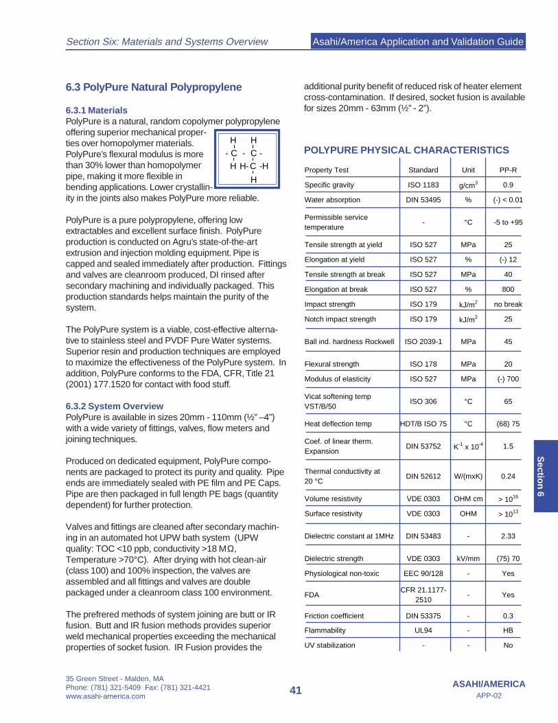
Asahi/America Application and Validation Guide
35 Green Street - Malden, MAPhone: (781) 321-5409 Fax: (781) 321-4421www.asahi-america.com
41ASAHI/AMERICA
APP-02
Section Six: Materials and Systems Overview
Sectio
n 6
6.3 PolyPure Natural Polypropylene
6.3.1 MaterialsPolyPure is a natural, random copolymer polypropyleneoffering superior mechanical proper-ties over homopolymer materials.PolyPure’s flexural modulus is morethan 30% lower than homopolymerpipe, making it more flexible inbending applications. Lower crystallin-ity in the joints also makes PolyPure more reliable.
PolyPure is a pure polypropylene, offering lowextractables and excellent surface finish. PolyPureproduction is conducted on Agru’s state-of-the-artextrusion and injection molding equipment. Pipe iscapped and sealed immediately after production. Fittingsand valves are cleanroom produced, DI rinsed aftersecondary machining and individually packaged. Thisproduction standards helps maintain the purity of thesystem.
The PolyPure system is a viable, cost-effective alterna-tive to stainless steel and PVDF Pure Water systems.Superior resin and production techniques are employedto maximize the effectiveness of the PolyPure system. Inaddition, PolyPure conforms to the FDA, CFR, Title 21(2001) 177.1520 for contact with food stuff.
6.3.2 System OverviewPolyPure is available in sizes 20mm - 110mm (½” –4”)with a wide variety of fittings, valves, flow meters andjoining techniques.
Produced on dedicated equipment, PolyPure compo-nents are packaged to protect its purity and quality. Pipeends are immediately sealed with PE film and PE Caps.Pipe are then packaged in full length PE bags (quantitydependent) for further protection.
Valves and fittings are cleaned after secondary machin-ing in an automated hot UPW bath system (UPWquality: TOC <10 ppb, conductivity >18 ΜΩ,Temperature >70°C). After drying with hot clean-air(class 100) and 100% inspection, the valves areassembled and all fittings and valves are doublepackaged under a cleanroom class 100 environment.
The prefrered methods of system joining are butt or IRfusion. Butt and IR fusion methods provides superiorweld mechanical properties exceeding the mechanicalproperties of socket fusion. IR Fusion provides the
H H
- C - C -
H H- C -H
H
additional purity benefit of reduced risk of heater elementcross-contamination. If desired, socket fusion is availablefor sizes 20mm - 63mm (½” - 2”).
POLYPURE PHYSICAL CHARACTERISTICS
Property Test Standard Unit PP-R
Specific gravity ISO 1183 g/cm3 0.9
Water absorption DIN 53495 % (-) < 0.01
Permissible service temperature
- °C -5 to +95
Tensile strength at yield ISO 527 MPa 25
Elongation at yield ISO 527 % (-) 12
Tensile strength at break ISO 527 MPa 40
Elongation at break ISO 527 % 800
Impact strength ISO 179 kJ/m2 no break
Notch impact strength ISO 179 kJ/m2 25
Ball ind. hardness Rockwell ISO 2039-1 MPa 45
Flexural strength ISO 178 MPa 20
Modulus of elasticity ISO 527 MPa (-) 700
Vicat softening tempVST/B/50
ISO 306 °C 65
Heat deflection temp HDT/B ISO 75 °C (68) 75
Coef. of linear therm. Expansion
DIN 53752 K-1 x 10⁻⁴ 1.5
Thermal conductivity at20 °C
DIN 52612 W/(mxK) 0.24
Volume resistivity VDE 0303 OHM cm > 1016
Surface resistivity VDE 0303 OHM > 1013
Dielectric constant at 1MHz DIN 53483 - 2.33
Dielectric strength VDE 0303 kV/mm (75) 70
Physiological non-toxic EEC 90/128 - Yes
FDACFR 21.1177-
2510- Yes
Friction coefficient DIN 53375 - 0.3
Flammability UL94 - HB
UV stabilization - - No
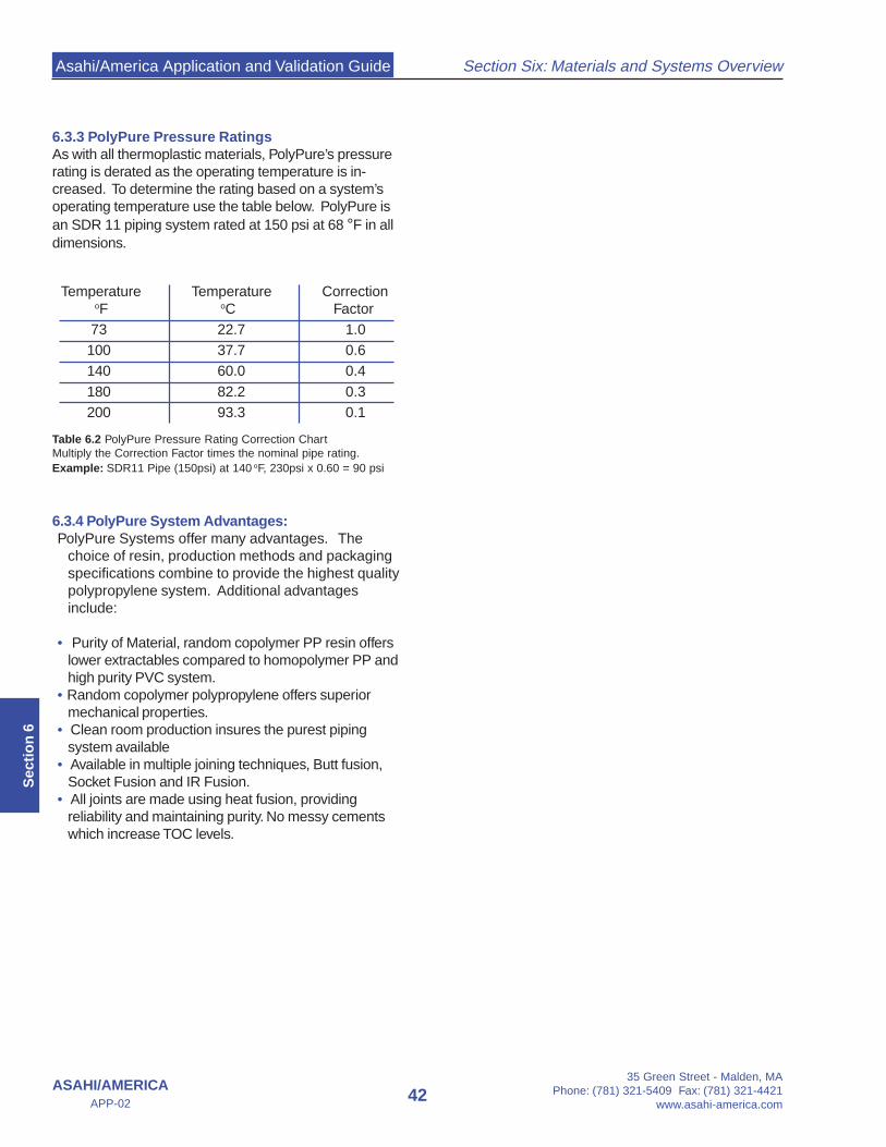
Asahi/America Application and Validation Guide
35 Green Street - Malden, MAPhone: (781) 321-5409 Fax: (781) 321-4421
www.asahi-america.com42
Section Six: Materials and Systems Overview
ASAHI/AMERICAAPP-02
Sec
tio
n 6
6.3.3 PolyPure Pressure RatingsAs with all thermoplastic materials, PolyPure’s pressurerating is derated as the operating temperature is in-creased. To determine the rating based on a system’soperating temperature use the table below. PolyPure isan SDR 11 piping system rated at 150 psi at 68 °F in alldimensions.
6.3.4 PolyPure System Advantages:PolyPure Systems offer many advantages. The
choice of resin, production methods and packagingspecifications combine to provide the highest qualitypolypropylene system. Additional advantagesinclude:
• Purity of Material, random copolymer PP resin offerslower extractables compared to homopolymer PP andhigh purity PVC system.
• Random copolymer polypropylene offers superiormechanical properties.
• Clean room production insures the purest pipingsystem available
• Available in multiple joining techniques, Butt fusion,Socket Fusion and IR Fusion.
• All joints are made using heat fusion, providingreliability and maintaining purity. No messy cementswhich increase TOC levels.
Temperature Temperature Correction oF oC Factor
73 22.7 1.0100 37.7 0.6140 60.0 0.4180 82.2 0.3200 93.3 0.1
Table 6.2 PolyPure Pressure Rating Correction ChartMultiply the Correction Factor times the nominal pipe rating.Example: SDR11 Pipe (150psi) at 140 oF, 230psi x 0.60 = 90 psi

Asahi/America Application and Validation Guide
35 Green Street - Malden, MAPhone: (781) 321-5409 Fax: (781) 321-4421www.asahi-america.com
43ASAHI/AMERICA
APP-02
Section Six: Materials and Systems Overview
Sectio
n 6
6.4 Proline Pigmented Polypropylene
6.4.1 MaterialsProline systems are pigmentedpolypropylene and are manufacturedfrom random copolymer resin.Copolymer materials offer superiormechanical properties over ho-mopolymer materials. Proline’sflexural modulus is more than 30% lower than homopoly-mer pipe, making it more flexible in bending applications.Lower crystallinity in the joints also makes Prolinesystems more reliable.
Proline systems have an extremely large applicationrange. Equally suited for UPW transport, caustic CIPdistribution or aggressive vent systems, Proline providesmaximum system flexibility.
6.4.2 System OverviewProline is readily available in sizes 20mm to 630mm (1/2”through 24”) and can be supplied in sizes up to 1400mm(54”). The wide size range is supported by a full line ofmolded fittings and valves up to 400mm (20”).
Proline systems are supplied as SDR11 or SDR33 withrespected pressure ratings of 150psi and 45psi. Addi-tional ratings are available upon request.
High Purity Proline pipe is immediately packaged afterproduction and is sealed on each end with a PE film andPE cap. The pipe is then sleeved in the PE and heatsealed on each end. Pipes are shipped in rigid PE tubeswhich are non-particle generating and resistant tomoisture and impacts.
High purity grades of Proline valves and fittings arecleaned after secondary machining in an automated hotUPW bath system (UPW quality: TOC <10 ppb,conductivity >18 ΜΩ, Temperature >70°C). Afterdrying with hot clean-air (class 100) and 100%inspection, the valves are assembled and all fittings andvalves are double packaged under a cleanroom class100 environment.
Proline systems are joined by a variety if methods. ForPW, IR is commonly specified. Butt and socket fusionare available options. For vent systems, butt fusion orslip coupling welding can be utilized depending uponsystem size.
H H
- C - C -
H H- C -H
H
PROLINE PHYSICAL CHARACTERISTICS
Property Test Standard Unit PP-R
Specific gravity ISO 1183 g/cm3 0.9
Water absorption DIN 53495 % (-) < 0.01
Permissible service temperature
- °C -5 to +95
Tensile strength at yield ISO 527 MPa 25
Elongation at yield ISO 527 % (-) 12
Tensile strength at break ISO 527 MPa 40
Elongation at break ISO 527 % 800
Impact strength ISO 179 kJ/m2 no break
Notch impact strength ISO 179 kJ/m2 25
Ball ind. hardness Rockwell ISO 2039-1 MPa 45
Flexural strength ISO 178 MPa 20
Modulus of elasticity ISO 527 MPa (-) 700
Vicat softening tempVST/B/50
ISO 306 °C 65
Heat deflection temp HDT/B ISO 75 °C (68) 75
Coef. of linear therm. Expansion
DIN 53752 K-1 x 10⁻⁴ 1.5
Thermal conductivity at20 °C
DIN 52612 W/(mxK) 0.24
Volume resistivity VDE 0303 OHM cm > 1016
Surface resistivity VDE 0303 OHM > 1013
Dielectric constant at 1MHz DIN 53483 - 2.33
Dielectric strength VDE 0303 kV/mm (75) 70
Physiological non-toxic EEC 90/128 - Yes
FDACFR 21.1177-
2510- Yes
Friction coefficient DIN 53375 - 0.3
Flammability UL94 - HB
UV stabilization - - Limited
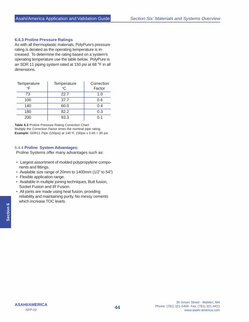
Asahi/America Application and Validation Guide
35 Green Street - Malden, MAPhone: (781) 321-5409 Fax: (781) 321-4421
www.asahi-america.com44
Section Six: Materials and Systems Overview
ASAHI/AMERICAAPP-02
Sec
tio
n 6
6.4.3 Proline Pressure RatingsAs with all thermoplastic materials, PolyPure’s pressurerating is derated as the operating temperature is in-creased. To determine the rating based on a system’soperating temperature use the table below. PolyPure isan SDR 11 piping system rated at 150 psi at 68 °F in alldimensions.
6.4.4 Proline System Advantages:Proline Systems offer many advantages such as:
• Largest assortment of molded polypropylene compo-nents and fittings.
• Available size range of 20mm to 1400mm (1/2” to 54”)• Flexible application range.• Available in multiple joining techniques, Butt fusion,
Socket Fusion and IR Fusion.• All joints are made using heat fusion, providing
reliability and maintaining purity. No messy cementswhich increase TOC levels.
Temperature Temperature Correction oF oC Factor
73 22.7 1.0100 37.7 0.6140 60.0 0.4180 82.2 0.3200 93.3 0.1
Table 6.3 Proline Pressure Rating Correction ChartMultiply the Correction Factor times the nominal pipe rating.Example: SDR11 Pipe (150psi) at 140 oF, 230psi x 0.60 = 90 psi

Asahi/America Application and Validation Guide
35 Green Street - Malden, MAPhone: (781) 321-5409 Fax: (781) 321-4421www.asahi-america.com
47ASAHI/AMERICA
APP-02
Section Seven: Piping Design
Sectio
n 7
Section SevenPiping DesignHigh Purity Water Systems
7.0 Introduction
A pure water system comprised of PVDF or NaturalPolypropylene is similar to that of most chemical feedsystems. The critical difference in a pure system is todesign it as a continuous recirculating loop with mini-mized dead legs and maintain extremely low TOC levelsin order to inhibit microbial growth.
Systems should also be sized to have turbulent flow as apart of the strategy of inhibiting bacteria growth. PVDFand PP systems are ideally suited for pure water as theyhave extremely smooth inner surfaces which reduceparticle generation and inhibit sites for bacteria to adhereto and proliferate. In addition, PVDF and PP systemshave low extractables, thus not contaminating the waterbeing transported.
In designing a thermoplastic water system, the followingitems need to be considered:
• Material of Construction• Operating Parameters• System Sizing• Thermal Expansion/Hanging Methods• Instrumentation and Controls• Sanitization Methods• Welding Method• Dead Leg Reduction and End-Point Configuration
7.1 Materials of Construction
The Purad High Purity PVDF Piping System is thepremier system for Pure Water applications. PVDF hasbeen used in Pure Water Systems for over fifteen years.Purad combines excellent surface finish with extremelylow extractables to provide the highest quality pipingmaterial. In addition to purity attributes, Purad also has awide variety components and welding methods wellsuited for HP applications. Purad is a crystalline materialthat can withstand high pressures. However, all PVDF ismore brittle than PP and requires special planning andhandling during installation. These requirements are nowcommonplace on the market and are accepted asstandard operating methods. For the strictest applica-tions, requiring low bacteria counts and virtually unde-
tectable levels of metal ions, Purad PVDF is recom-mended for the service.
For less stringent water quality applications, PolyPureNatural Polypropylene is an excellent alternative.PolyPure offers excellent surface smoothness, as wellas, low extractable levels as compared to stainless steel.PolyPure systems are thermally fused together, eliminat-ing the use of glues, which will continue to leach into awater system for extended periods of time. Polypropy-lene is an extremely weldable material, making fusionjoints that are simple and reliable.
Operating ParametersBecause thermoplastic systems have varying ratings atdifferent temperatures it is important to design asystem around all the parameters it will be subjectedto. The following operating parameters should beverified:
• Continuous operating Temperature• Continuous operating Pressure• Flow rates
Knowledge of the above parameters is required in orderto determine the suitability of thermoplastics for yourapplication. Compare the actual conditions to theallowable ratings of the material being selected for thejob. It is important to predict elevated temperatures, asthermoplastics have reduced pressure ratings at highertemperature. Valves should be verified in terms oftemperature and pressure separately from a pipingsystem, as certain styles and brands of valves havelower ratings than that of the pipe system.
After verifying the standard operating conditions, it isnecessary to examine other operations that might effectthe piping. The following is a sample of items to consider,prior to specifying a material:
• Will there be spikes in temperature or pressure?• Is there a cleaning or sanitization operation that
the piping will be exposed to?• If yes, what is the cleaning agent?• What temperature will cleaning be conducted at?• Will the system be exposed to Sunlight or employ
other sources of UV radiation?
Each of the above questions should be answered andthe desired material should be checked for suitabilitybased on the above factors as well as any others thatmight be special to the system in question.
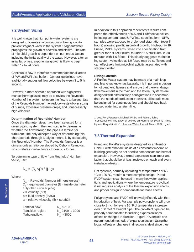
Asahi/America Application and Validation Guide
35 Green Street - Malden, MAPhone: (781) 321-5409 Fax: (781) 321-4421
www.asahi-america.com48
Section Seven: Piping Design
ASAHI/AMERICAAPP-02
Sec
tio
n 7
7.2 System Sizing
It is well known that high purity water systems aredesigned to operate in a continuously flowing loop toprevent stagnant water in the system. Stagnant waterpropagates the growth of bacteria and biofilm. The rateof microbial growth is dependent on numerous factorsincluding the initial quality of the water. However, after aninitial lag phase, exponential growth is likely to beginwithin 12 to 24 hours.
Continuous flow is therefore recommended for all areasof PW and WFI distribution. General guidelines havetraditionally suggested flow velocities between 3 to 5 ft/second.
However, a more sensible approach with high perfor-mance thermoplastics may be to review the ReynoldsNumber of the system to insure the flow is turbulent. Useof the Reynolds Number may reduce wasteful over sizingof pumps, excessive pressure drops, and unnecessarilyhigh velocities.
Determination of Reynolds’ NumberOnce the diameter sizes have been selected for agiven piping system, the next step is to determinewhether the flow through the pipes is laminar orturbulent. The only accepted way of determining thischaracteristic through analytic means is by calculatingthe Reynolds’ Number. The Reynolds’ Number is adimensionless ratio developed by Osborn Reynolds,which relates inertial forces to viscous forces.
To determine type of flow from Reynolds’ Numbervalue, use:
Nre = (D
e vρ) / (µ g)
Where:N
re = Reynolds’ Number (dimensionless)
De = equivalent diameter (ft = inside diameter
fully-filled circular pipe)v = velocity (ft/s)ρ = fluid density (lb/ft3)µ = relative viscosity (lb x sec/ft2)
Laminar flow: Nre < 2100
Transition region: Nre 2100 to 3000
Turbulent flow: Nre > 3000
In addition to this approach recent tests results com-pared the effectiveness of 0.5 and 1.0ft/sec velocitiesin rinsing contaminated UPW into specification1. UPWsamples were exposed to prolonged stagnation (over 8hours) allowing prolific microbial growth. High-purity, IRFused, PVDF systems rinsed into specification fromgreater than 90 cfu/100ml to under 2.5 cfu/100ml in 30minutes with 1.0 ft/sec. This clearly suggests maintain-ing system velocities at 1.0 ft/sec may be sufficient andcan effectively limit microbial activity associated withstagnant water.
Sizing LateralsA Purified Water system may be made of a main loopand branches known as Laterals. It is important in designto not dead end laterals and ensure that there is alwaysflow movement in the main and the lateral. Systems aredesigned with different loop configurations to accommo-date the needs of production. However, all laterals mustbe designed for continuous flow and should feed backunused water into a return line.
1. Lee, Ron; Patterson, Michael, Ph.D.; and Painter, John;“Semicondutors: The Effect of Velocity on High-Purity Systems RinseUp and Requalification”; Ultrapure Water Journal; March 2002; pg 41.
7.3 Thermal Expansion
Purad and PolyPure systems designed for ambient orCold DI water that are inside at a constant temperaturebuilding generally do not need to compensate for thermalexpansion. However, thermal expansion is an importantfactor that should be at least reviewed on each and everyinstallation design.
Hot systems, normally operating at temperatures of 65°C to 120 °C, require a more complex design. PuradPVDF systems can be used in many hot water applica-tions and applications where the temperature is cyclical,it just requires analysis of the thermal expansion effectsand proper design to compensate for those effects.
Polypropylene and PVDF will grow significantly with theintroduction of heat. For example polypropylene will growclose to 1 inch for every 10 ºF of temperature increaseover 100 feet of straight pipe. The growth of pipe can beproperly compensated for utilizing expansion loops,offsets or changes in direction. Figure 7.A depicts onerecommended methods of expansion design. Using theloops, offsets or changes in direction is ideal since they

Asahi/America Application and Validation Guide
35 Green Street - Malden, MAPhone: (781) 321-5409 Fax: (781) 321-4421www.asahi-america.com
49ASAHI/AMERICA
APP-02
Section Seven: Piping Design
Sectio
n 7
Process Step Measurement Type Readout Location
PVC Vortex Flow Meter Line Mount
Totalizer Wall Mount
PVC/PP Vortex Flow Meter Line Mount
Supply Water Temperature Line Mount
Media Filter Pressure Gauges Line Mount
RO Low Feed Pressure Alarm at RO Panel
RO Product Totalizer RO Panel
PP/PVDF Product Vortex Flow Meter
RO Panel
RO Reject Flow Meter/Total RO Panel
RO Reject Recirculation RO Panel
RO Percent Ion Rejection RO Panel
Mix Bed Polish Resitivity Polisher Panel
Point of Distribution Resitivity Polisher Panel
PP/PVDF Supply Vortex Flow Meter
Line / PLC
PP/PVDF Return Vortex Flow Meter
Line / PLC
Distribution Loop
Pretreatment
Purification
Post Treatment
Feed Water
are homogenous with the pipe system. Other devicessuch as pistons or bellows can also be used, but are notrecommended for PW or WFI applications as they rely onmechanical features and connections that could leak overtime and are not compatible with sanitary design.
For a thorough review of thermal expansion and properdesign, consult Section C of the Asahi/America Engineer-ing Design Guide.
Hot DI systems also reduce the rigidity of thermoplasticpiping systems, which in turn decreases the supportspacing between pipe hangers. In smaller dimensions itis recommended to use continuous support made ofsome type channel or split plastic pipe.
The use of hangers as guides and anchors becomesimportant. As the design procedures in Section C of theEngineering Design Guide indicate, certain hangersshould be used as guides to allow the pipe to move backand forth in-line, while other hangers shall be anchoringlocations used to direct the expansion into the compen-sating device. The anchors and hangers should bedesigned to withstand the end load generated by the
Thermal Expansion. Figure 7.B an example of an anchortype fitting with a fixing pipe clamp available from Asahi/America, Inc.
7.4 Instrumentation and Controls
In the proper design of an Ultra Pure Water system it isimportant to monitor the quality of the water, tempera-ture, pressure and the flow rate.
The following chart outlines recommended instrumentsand sample points along with their location in the Pro-cess.Instrumentation Type and Location
Figure 7.B Fixed Anchor Design
Figure 7.A An Example of one Thermal Expansion DesignOptions
Offset
F ... fixpoint or anchorsLP ... pipe support (e.g. pipe clips)
Ls... Minimum straight length
L s
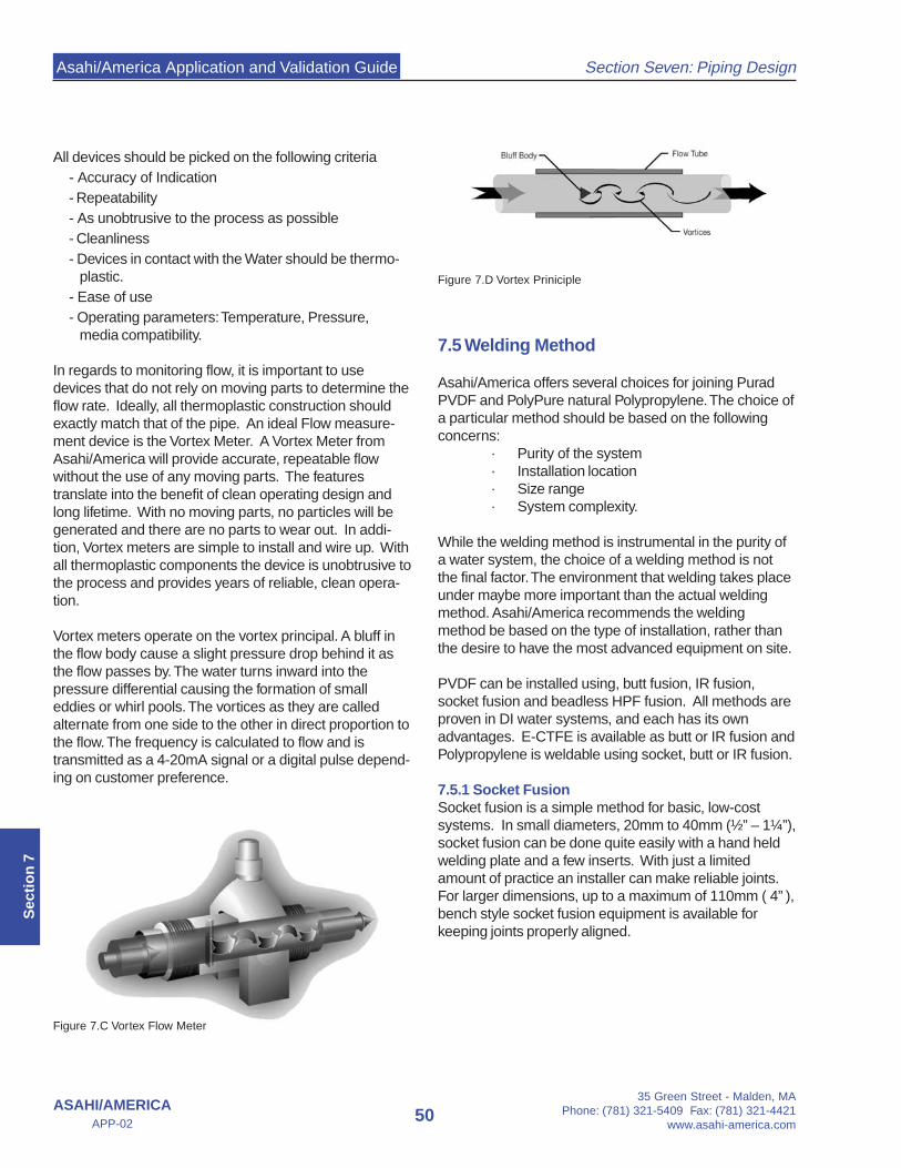
Asahi/America Application and Validation Guide
35 Green Street - Malden, MAPhone: (781) 321-5409 Fax: (781) 321-4421
www.asahi-america.com50
Section Seven: Piping Design
ASAHI/AMERICAAPP-02
Sec
tio
n 7
All devices should be picked on the following criteria- Accuracy of Indication- Repeatability- As unobtrusive to the process as possible- Cleanliness- Devices in contact with the Water should be thermo-
plastic.- Ease of use- Operating parameters: Temperature, Pressure,
media compatibility.
In regards to monitoring flow, it is important to usedevices that do not rely on moving parts to determine theflow rate. Ideally, all thermoplastic construction shouldexactly match that of the pipe. An ideal Flow measure-ment device is the Vortex Meter. A Vortex Meter fromAsahi/America will provide accurate, repeatable flowwithout the use of any moving parts. The featurestranslate into the benefit of clean operating design andlong lifetime. With no moving parts, no particles will begenerated and there are no parts to wear out. In addi-tion, Vortex meters are simple to install and wire up. Withall thermoplastic components the device is unobtrusive tothe process and provides years of reliable, clean opera-tion.
Vortex meters operate on the vortex principal. A bluff inthe flow body cause a slight pressure drop behind it asthe flow passes by. The water turns inward into thepressure differential causing the formation of smalleddies or whirl pools. The vortices as they are calledalternate from one side to the other in direct proportion tothe flow. The frequency is calculated to flow and istransmitted as a 4-20mA signal or a digital pulse depend-ing on customer preference.
7.5 Welding Method
Asahi/America offers several choices for joining PuradPVDF and PolyPure natural Polypropylene. The choice ofa particular method should be based on the followingconcerns:
· Purity of the system· Installation location· Size range· System complexity.
While the welding method is instrumental in the purity ofa water system, the choice of a welding method is notthe final factor. The environment that welding takes placeunder maybe more important than the actual weldingmethod. Asahi/America recommends the weldingmethod be based on the type of installation, rather thanthe desire to have the most advanced equipment on site.
PVDF can be installed using, butt fusion, IR fusion,socket fusion and beadless HPF fusion. All methods areproven in DI water systems, and each has its ownadvantages. E-CTFE is available as butt or IR fusion andPolypropylene is weldable using socket, butt or IR fusion.
7.5.1 Socket FusionSocket fusion is a simple method for basic, low-costsystems. In small diameters, 20mm to 40mm (½” – 1¼”),socket fusion can be done quite easily with a hand heldwelding plate and a few inserts. With just a limitedamount of practice an installer can make reliable joints.For larger dimensions, up to a maximum of 110mm ( 4” ),bench style socket fusion equipment is available forkeeping joints properly aligned.
Figure 7.C Vortex Flow Meter
Figure 7.D Vortex Priniciple

Asahi/America Application and Validation Guide
35 Green Street - Malden, MAPhone: (781) 321-5409 Fax: (781) 321-4421www.asahi-america.com
51ASAHI/AMERICA
APP-02
Section Seven: Piping Design
Sectio
n 7
7.5.3 Butt FusionButt fusion is similar to IR fusion, however the compo-nents to be welded are in contact with the heat source.Butt fusion is the parent of IR fusion and still maintains itsone advantage; it can be done in a variety of environ-ments. Wind or a strong breeze can make IR weldingtroublesome, for these cases butt fusion is preferred.Additionally, field or in-place welds should be performedwith butt fusion. A variety of different types of butt fusionequipment are available, making location welds possible,where an IR would not be.
7.5.4 HPF FusionHPF Fusion is a welding method that combines a smoothinternal seam with practical portability. It is available in½” – 2” PVDF. The method is simple in use. Pipe issimply inserted into a coupling and locked into placeusing a clamp. The tool is set for each weld using a barcode scanner to set the parameters. As the coupling iselectrified the heat joins the pipe and coupling together.Inside the pipe an internal balloon is used to maintain theshape of the pipe. The weld can also be accomplishedwithout an internal balloon. In this case the heat isstopped prior to reaching the internal pipe diameter. In
7.5.3 IR FusionFor systems that have larger dimensions above 110mm(4”), butt and IR fusion make a logical choice. Bothsystems are available for welding all dimensions from20mm to 250mm (½” to 10”). IR fusion has severaladvantages; during the welding process the material isnot in contact with the heat source, thus eliminating apossible source of contamination. In the course of an IRweld there is no force against the heating element like inbutt fusion, therefore the weld beads are smaller whenmaking an IR weld. In a flowing system an IR bead willflush cleaner, due to its round, smoother shape ascompared to a butt weld.
IR fusion is neat, clean and reliable. Current day weldingequipment is computer controlled making each weldidentical and making the inspection processes morereliable. IR fusion equipment also allows for completetraceability of each weld, by each operator.IR fusion is suited for clean room environments andbench top type welding. Equipment is highly sophisti-cated and is not generally recommended for making fieldor location welds.
Figure 7.F Steps of IR Non-Contact FusionFigure 7.E Steps of Socket Fusion
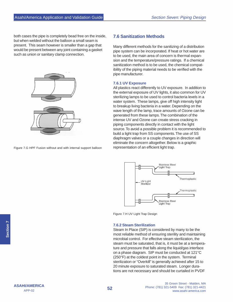
Asahi/America Application and Validation Guide
35 Green Street - Malden, MAPhone: (781) 321-5409 Fax: (781) 321-4421
www.asahi-america.com52
Section Seven: Piping Design
ASAHI/AMERICAAPP-02
Sec
tio
n 7
7.6 Sanitization Methods
Many different methods for the sanitizing of a distributionpipe system can be incorporated. If heat or hot water areto be used, the main area of concern is thermal expan-sion and the temperature/pressure ratings. If a chemicalsanitization method is to be used, the chemical compat-ibility of the piping material needs to be verified with thepipe manufacturer.
7.6.1 UV ExposureAll plastics react differently to UV exposure. In addition tothe external exposure of UV lights, it also common for UVsterilizing lamps to be used to control bacteria levels in awater system. These lamps, give off high intensity lightto breakup living bacteria in a water. Depending on thewave length of the lamp, trace amounts of Ozone can begenerated from these lamps. The combination of theintense UV and Ozone can create stress cracking inpiping components directly in contact with the lightsource. To avoid a possible problem it is recommended tobuild a light trap from SS components. The use of SSdiaphragm valves or a couple changes in direction willeliminate the concern altogether. Below is a graphicrepresentation of an efficient light trap.
7.6.2 Steam SterilizationSteam In Place (SIP) is considered by many to be themost reliable method of ensuring sterility and maintainingmicrobial control. For effective steam sterilization, thesteam must be saturated, that is, it must be at a tempera-ture and pressure that falls along the liquid/gas interfaceon a phase diagram. SIP must be conducted at 121°C(250°F) at the coldest point in the system. Terminalsterilization or “Overkill” is generally achieved after 15 to20 minute exposure to saturated steam. Longer dura-tions are not necessary and should be curtailed in PVDF
Figure 7.G HPF Fusion without and with internal support balloon
both cases the pipe is completely bead free on the inside,but when welded without the balloon a small seam ispresent. This seam however is smaller than a gap thatwould be present between any joint containing a gasketsuch as union or sanitary clamp connection.
Figure 7.H UV Light Trap Design

Asahi/America Application and Validation Guide
35 Green Street - Malden, MAPhone: (781) 321-5409 Fax: (781) 321-4421www.asahi-america.com
53ASAHI/AMERICA
APP-02
Section Seven: Piping Design
Sectio
n 7
lines at periods 30 minutes or shorter is perfectly accept-able. However, care should be taken with use of Ozonein PP systems. Please consult our Engineering Depart-ment for exact application guidelines concerning the useof Ozone.
7.7 Hanging
Polymer piping systems act differently than metal pipingsystems and varying hanger styles are required. Thethree uses of hangers are as a support, a guide and/oran anchor. The hanger itself may be used to accomplishtwo of these goals, but all three uses need to be consid-ered when laying out the hanger configuration. Thedesigner of a system should specify the exact hangerand location and not leave this up to the installer.
Support spacing for thermoplastic piping systems differsgreatly as compared to metallic piping. It generallyrequires more supports, and the introduction of highertemps will further increase that support spacing require-ment. For support space requirements by
Hangers that evenly grip 360 degrees around the pipeare preferred. Clamps, such as U-bolts, can tighten downon the pipe providing a pin point load on the pipe that canlead to eventual damage. Thermoplastic clamps arerecommended when installing a thermoplastic pipesystem. Above is a detail of a recommended clamp. If ametal clamp is to be utilized, a rubber gasket materialshould be placed between the pipe and the clamp as acushion to protect the pipe. Clamps should be checkedfor sharp or jagged edges that could scrape or penetratethe pipe.
For thorough hanging design recommendations, refer toAsahi/America’s Engineering and Design Guide.
systems. A heat penetration study documenting suffi-cient temperature is maintained throughout the pipingsystem is critical to validation.
Steam sterilized Purad PVDF systems offer severaladvantages over those constructed of stainless steel.Purad PVDF’s extremely low thermal conductance factorof 1.32 Btu-in/hr ft2 minimizes heat loss. Heat penetra-tion throughout a system is more easily ensured withoutthe need for pipe insulation. Purad PVDF can safelytransport hot media without risk of serious injury to thosewho may come in contact with it. Additionally, the hottemperatures do not contribute to accelerated corrosionas is the case in with stainless steels. Clean steam ishighly corrosive to stainless steels. High grades, such as316L, are not immune to its corrosive effects. Thecorrosion can contribute to degradation of the system’soverall water quality. Purad PVDF, on the other hand,can handle SIP without corrosion and without restorativepassivation requirements. This is an important factor toconsider when selecting system material of constructionand determining operating and maintenance costs.
Recommended SIP Parameters for Purad PVDF*Temperature 121-130 °CGauge Pressure 15-25 psigDuration 15-20 minutesFrequency As Needed
*Values based on SDR21 Pipe and Fittings. Valves and othercomponents should also be checked for suitability. SIP necessitatesexpansion calculations and compensation.
7.6.3 Ozone SterilizationOzone is currently under utilized in Life Science waterapplications. Ozone is an extremely effective method ofsanitation. Bacteria are easily destroyed at low concen-tration levels and with limited exposure. Ozone concen-trations of 0.2 to 0.5ppm and at contact times as little as10 minutes are recommended for water sterilization.Ozone can be destroyed downstream of point of injectionby UV sterilization lights.
Ozone is a strong oxidant. As such, material compatibil-ity issues need to be considered. Extended exposuremay deteriorate gasket materials and some pipingmaterials. Purad PVDF is fully resistant to Ozone asused for sanitation control. High concentrations of Ozoneare harmful to all PP . However, effective levels may beintroduced into Proline and PolyPure systems. WeeklyCIP with Ozone at 0.2-0.5ppm in Proline and PolyPure
Figure 7.I Recommended Pipe Hanger Design
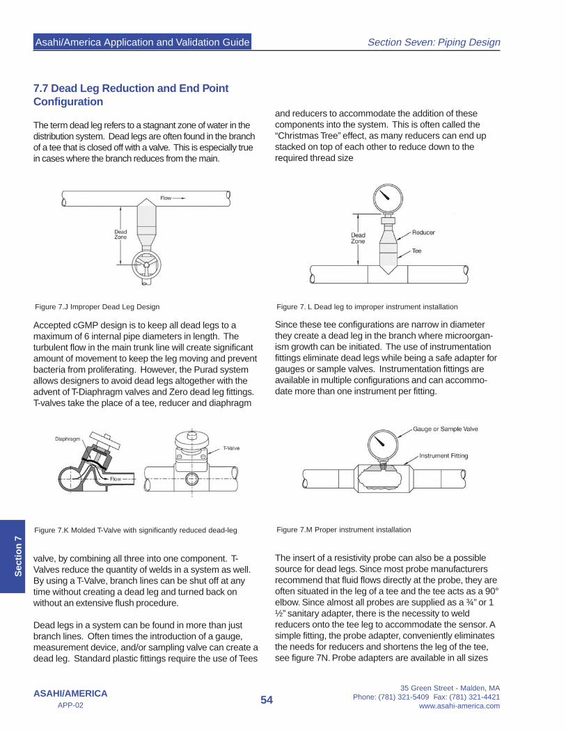
Asahi/America Application and Validation Guide
35 Green Street - Malden, MAPhone: (781) 321-5409 Fax: (781) 321-4421
www.asahi-america.com54
Section Seven: Piping Design
ASAHI/AMERICAAPP-02
Sec
tio
n 7
7.7 Dead Leg Reduction and End PointConfiguration
The term dead leg refers to a stagnant zone of water in thedistribution system. Dead legs are often found in the branchof a tee that is closed off with a valve. This is especially truein cases where the branch reduces from the main.
Accepted cGMP design is to keep all dead legs to amaximum of 6 internal pipe diameters in length. Theturbulent flow in the main trunk line will create significantamount of movement to keep the leg moving and preventbacteria from proliferating. However, the Purad systemallows designers to avoid dead legs altogether with theadvent of T-Diaphragm valves and Zero dead leg fittings.T-valves take the place of a tee, reducer and diaphragm
valve, by combining all three into one component. T-Valves reduce the quantity of welds in a system as well.By using a T-Valve, branch lines can be shut off at anytime without creating a dead leg and turned back onwithout an extensive flush procedure.
Dead legs in a system can be found in more than justbranch lines. Often times the introduction of a gauge,measurement device, and/or sampling valve can create adead leg. Standard plastic fittings require the use of Tees
and reducers to accommodate the addition of thesecomponents into the system. This is often called the“Christmas Tree” effect, as many reducers can end upstacked on top of each other to reduce down to therequired thread size
Since these tee configurations are narrow in diameterthey create a dead leg in the branch where microorgan-ism growth can be initiated. The use of instrumentationfittings eliminate dead legs while being a safe adapter forgauges or sample valves. Instrumentation fittings areavailable in multiple configurations and can accommo-date more than one instrument per fitting.
The insert of a resistivity probe can also be a possiblesource for dead legs. Since most probe manufacturersrecommend that fluid flows directly at the probe, they areoften situated in the leg of a tee and the tee acts as a 90°elbow. Since almost all probes are supplied as a ¾” or 1½” sanitary adapter, there is the necessity to weldreducers onto the tee leg to accommodate the sensor. Asimple fitting, the probe adapter, conveniently eliminatesthe needs for reducers and shortens the leg of the tee,see figure 7N. Probe adapters are available in all sizes
Figure 7.J Improper Dead Leg Design
Figure 7.K Molded T-Valve with significantly reduced dead-leg
Figure 7. L Dead leg to improper instrument installation
Figure 7.M Proper instrument installation
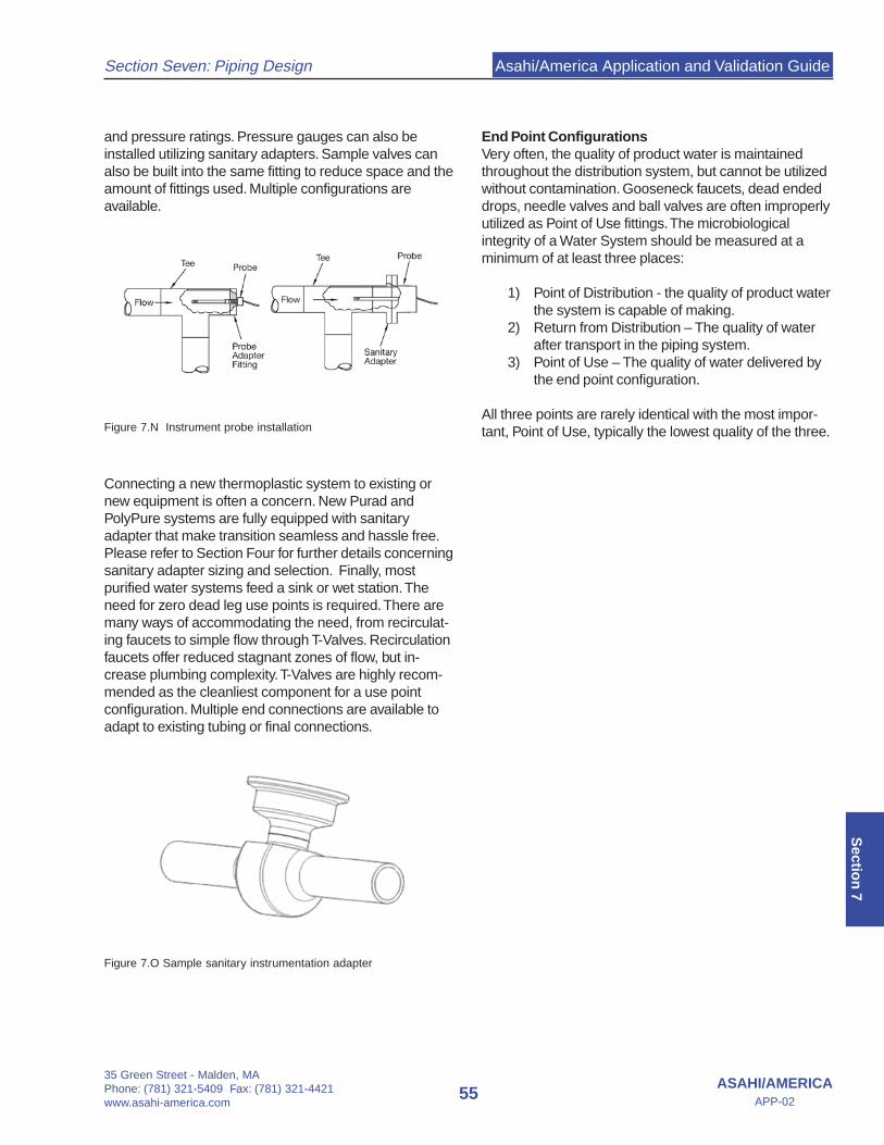
Asahi/America Application and Validation Guide
35 Green Street - Malden, MAPhone: (781) 321-5409 Fax: (781) 321-4421www.asahi-america.com
55ASAHI/AMERICA
APP-02
Section Seven: Piping Design
Sectio
n 7
and pressure ratings. Pressure gauges can also beinstalled utilizing sanitary adapters. Sample valves canalso be built into the same fitting to reduce space and theamount of fittings used. Multiple configurations areavailable.
Connecting a new thermoplastic system to existing ornew equipment is often a concern. New Purad andPolyPure systems are fully equipped with sanitaryadapter that make transition seamless and hassle free.Please refer to Section Four for further details concerningsanitary adapter sizing and selection. Finally, mostpurified water systems feed a sink or wet station. Theneed for zero dead leg use points is required. There aremany ways of accommodating the need, from recirculat-ing faucets to simple flow through T-Valves. Recirculationfaucets offer reduced stagnant zones of flow, but in-crease plumbing complexity. T-Valves are highly recom-mended as the cleanliest component for a use pointconfiguration. Multiple end connections are available toadapt to existing tubing or final connections.
Figure 7.O Sample sanitary instrumentation adapter
End Point ConfigurationsVery often, the quality of product water is maintainedthroughout the distribution system, but cannot be utilizedwithout contamination. Gooseneck faucets, dead endeddrops, needle valves and ball valves are often improperlyutilized as Point of Use fittings. The microbiologicalintegrity of a Water System should be measured at aminimum of at least three places:
1) Point of Distribution - the quality of product waterthe system is capable of making.
2) Return from Distribution – The quality of waterafter transport in the piping system.
3) Point of Use – The quality of water delivered bythe end point configuration.
All three points are rarely identical with the most impor-tant, Point of Use, typically the lowest quality of the three.Figure 7.N Instrument probe installation

ASAHI/AMERICA, INC.35 Green Street
P.O. Box 653Malden, MA 02148
Tel: 800-343-3618; 781-321-5409Fax: 800-426-7058
Email: [email protected]: www.asahi-america.com
ASAHI/AMERICA, INC.35 Green Street
P.O. Box 653Malden, MA 02148
Tel: 800-343-3618; 781-321-5409Fax: 800-426-7058
Email: [email protected]: www.asahi-america.com