Embed Size (px)
Citation preview

C H A P T E R 16
ASA FirePOWER (SFR) ModuleThis chapter describes how to configure the ASA FirePOWER module that runs on the ASA.
• The ASA FirePOWER Module, page 16-1
• Licensing Requirements for the ASA FirePOWER Module, page 16-6
• Guidelines for ASA FirePOWER, page 16-6
• Defaults for ASA FirePOWER, page 16-7
• Configure the ASA FirePOWER Module, page 16-7
• Managing the ASA FirePOWER Module, page 16-22
• Monitoring the ASA FirePOWER Module, page 16-26
• Examples for the ASA FirePOWER Module, page 16-29
• History for the ASA FirePOWER Module, page 16-30
The ASA FirePOWER ModuleThe ASA FirePOWER module supplies next-generation firewall services, including Next-Generation Intrusion Prevention System (NGIPS), Application Visibility and Control (AVC), URL filtering, and Advanced Malware Protection (AMP).You can use the module in single or multiple context mode, and in routed or transparent mode.
The module is also known as ASA SFR.
Although the module has a basic command line interface (CLI) for initial configuration and troubleshooting, you configure the security policy on the device using a separate application, FireSIGHT Management Center, which can be hosted on a separate FireSIGHT Management Center appliance or as a virtual appliance running on a VMware server. (FireSIGHT Management Center is also known as Defense Center.)
For ASA FirePOWER running on ASA 5506-X devices, you can optionally configure the device using ASDM rather than FireSIGHT Management Center.
• How the ASA FirePOWER Module Works with the ASA, page 16-2
• ASA FirePOWER Management Access, page 16-5
• Compatibility with ASA Features, page 16-6
16-1Cisco ASA Series Firewall CLI Configuration Guide

Chapter 16 ASA FirePOWER (SFR) Module The ASA FirePOWER Module
How the ASA FirePOWER Module Works with the ASAYou can configure your ASA FirePOWER module using one of the following deployment models:
• Inline mode—In an inline deployment, the actual traffic is sent to the ASA FirePOWER module, and the module’s policy affects what happens to the traffic. After dropping undesired traffic and taking any other actions applied by policy, the traffic is returned to the ASA for further processing and ultimate transmission.
• Inline tap monitor-only mode (ASA inline)—In an inline tap monitor-only deployment, a copy of the traffic is sent to the ASA FirePOWER module, but it is not returned to the ASA. Inline tap mode lets you see what the ASA FirePOWER module would have done to traffic, and lets you evaluate the content of the traffic, without impacting the network. However, in this mode, the ASA does apply its policies to the traffic, so traffic can be dropped due to access rules, TCP normalization, and so forth.
• Passive monitor-only (traffic forwarding) mode—If you want to prevent any possibility of the ASA with FirePOWER Services device impacting traffic, you can configure a traffic-forwarding interface and connect it to a SPAN port on a switch. In this mode, traffic is sent directly to the ASA FirePOWER module without ASA processing. The traffic is “black holed,” in that nothing is returned from the module, nor does the ASA send the traffic out any interface. You must operate the ASA in single context transparent mode to configure traffic forwarding.
Be sure to configure consistent policies on the ASA and the ASA FirePOWER. Both policies should reflect the inline or monitor-only mode of the traffic.
The following sections explain these modes in more detail.
ASA FirePOWER Inline Mode
In inline mode, traffic goes through the firewall checks before being forwarded to the ASA FirePOWER module. When you identify traffic for ASA FirePOWER inspection on the ASA, traffic flows through the ASA and the module as follows:
1. Traffic enters the ASA.
2. Incoming VPN traffic is decrypted.
3. Firewall policies are applied.
4. Traffic is sent to the ASA FirePOWER module.
5. The ASA FirePOWER module applies its security policy to the traffic, and takes appropriate actions.
6. Valid traffic is sent back to the ASA; the ASA FirePOWER module might block some traffic according to its security policy, and that traffic is not passed on.
7. Outgoing VPN traffic is encrypted.
8. Traffic exits the ASA.
The following figure shows the traffic flow when using the ASA FirePOWER module in inline mode. In this example, the module blocks traffic that is not allowed for a certain application. All other traffic is forwarded through the ASA.
16-2Cisco ASA Series Firewall CLI Configuration Guide

Chapter 16 ASA FirePOWER (SFR) Module The ASA FirePOWER Module
Figure 16-1 ASA FirePOWER Module Traffic Flow in the ASA
Note If you have a connection between hosts on two ASA interfaces, and the ASA FirePOWER service policy is only configured for one of the interfaces, then all traffic between these hosts is sent to the ASA FirePOWER module, including traffic originating on the non-ASA FirePOWER interface (because the feature is bidirectional).
ASA FirePOWER Inline Tap Monitor-Only Mode
This mode sends a duplicate stream of traffic to the ASA FirePOWER module for monitoring purposes only. The module applies the security policy to the traffic and lets you know what it would have done if it were operating in inline mode; for example, traffic might be marked “would have dropped” in events. You can use this information for traffic analysis and to help you decide if inline mode is desirable.
Note You cannot configure both inline tap monitor-only mode and normal inline mode at the same time on the ASA. Only one type of security policy is allowed. In multiple context mode, you cannot configure inline tap monitor-only mode for some contexts, and regular inline mode for others.
The following figure shows the traffic flow when operating in inline tap mode.
ASA
Main System
ASA FirePOWER
Diverted Traffic
ASA FirePOWERinspection
VPNDecryption
FirewallPolicy
Block
inside outside
3714
44
16-3Cisco ASA Series Firewall CLI Configuration Guide

Chapter 16 ASA FirePOWER (SFR) Module The ASA FirePOWER Module
Figure 16-2 ASA FirePOWER Inline Tap Monitor-Only Mode
ASA FirePOWER Passive Monitor-Only Traffic Forwarding Mode
If you want to operate the ASA FirePOWER module as a pure Intrusion Detection System (IDS), where there is no impact on the traffic at all, you can configure a traffic forwarding interface. A traffic forwarding interface sends all received traffic directly to the ASA FirePOWER module without any ASA processing.
The module applies the security policy to the traffic and lets you know what it would have done if it were operating in inline mode; for example, traffic might be marked “would have dropped” in events. You can use this information for traffic analysis and to help you decide if inline mode is desirable.
Traffic in this setup is never forwarded: neither the module nor the ASA sends the traffic on to its ultimate destination. You must operate the ASA in single context and transparent modes to use this configuration.
The following figure shows an interface configured for traffic-forwarding. That interface is connected to a switch SPAN port so the ASA FirePOWER module can inspect all of the network traffic. Another interface sends traffic normally through the firewall.
Figure 16-3 ASA FirePOWER Passive Monitor-Only, Traffic-Forwarding Mode
ASA
Main System
inside
ASA FirePOWER
ASA FirePOWER inspection
outsideVPN
DecryptionFirewallPolicy
Copied Traffic
3714
45
Gig 1/3
Gig 1/1
SPANPort
ASA
Main System
ASA FirePOWER Bac
kpla
ne
ASA FirePOWERinspection
Forwarded Traffic
Switch
4034
28
inside outsideVPNDecryption
FirewallPolicy
16-4Cisco ASA Series Firewall CLI Configuration Guide

Chapter 16 ASA FirePOWER (SFR) Module The ASA FirePOWER Module
ASA FirePOWER Management AccessThere are two separate layers of access for managing an ASA FirePOWER module: initial configuration (and subsequent troubleshooting) and policy management.
• Initial Configuration, page 16-5
• Policy Configuration and Management, page 16-5
Initial Configuration
For initial configuration, you must use the CLI on the ASA FirePOWER module. For information on the default management addresses, see Defaults for ASA FirePOWER, page 16-7.
To access the CLI, you can use the following methods:
• ASA 5585-X (hardware module):
– ASA FirePOWER console port—The console port on the module is a separate external console port.
– ASA FirePOWER Management 1/0 interface using SSH—You can connect to the default IP address or you can use ASDM to change the management IP address and then connect using SSH. The management interface on the module is a separate external Gigabit Ethernet interface.
Note You cannot access the ASA FirePOWER hardware module CLI over the ASA backplane using the session command.
• All other models (software module):
– ASA session over the backplane—If you have CLI access to the ASA, then you can session to the module and access the module CLI.
– ASA FirePOWER Management 0/0 interface using SSH (Management 1/1 for the 5506-X)—You can connect to the default IP address or you can use ASDM to change the management IP address and then connect using SSH. The ASA FirePOWER management interface shares the management interface with the ASA. Separate MAC addresses and IP addresses are supported for the ASA and ASA FirePOWER module. You must perform configuration of the ASA FirePOWER IP address within the ASA FirePOWER operating system (using the CLI or ASDM). However, physical characteristics (such as enabling the interface) are configured on the ASA. You can remove the ASA interface configuration (specifically the interface name) to dedicate this interface as an ASA FirePOWER-only interface. This interface is management-only.
Policy Configuration and Management
After you perform initial configuration, configure the ASA FirePOWER security policy using FireSIGHT Management Center (for all models) or ASDM (for 5506-X). Then configure the ASA policy for sending traffic to the ASA FirePOWER module using ASDM or Cisco Security Manager.
16-5Cisco ASA Series Firewall CLI Configuration Guide

Chapter 16 ASA FirePOWER (SFR) Module Licensing Requirements for the ASA FirePOWER Module
Compatibility with ASA FeaturesThe ASA includes many advanced application inspection features, including HTTP inspection. However, the ASA FirePOWER module provides more advanced HTTP inspection than the ASA provides, as well as additional features for other applications, including monitoring and controlling application usage.
To take full advantage of the ASA FirePOWER module features, use the following guidelines for traffic that you send to the ASA FirePOWER module:
• Do not configure ASA inspection on HTTP traffic.
• Do not configure Cloud Web Security (ScanSafe) inspection. If you configure both ASA FirePOWER inspection and Cloud Web Security inspection for the same traffic, the ASA only performs ASA FirePOWER inspection.
• Other application inspections on the ASA are compatible with the ASA FirePOWER module, including the default inspections.
• Do not enable the Mobile User Security (MUS) server; it is not compatible with the ASA FirePOWER module.
Licensing Requirements for the ASA FirePOWER ModuleThe ASA FirePOWER module and FireSIGHT Management Center require additional licenses, which need to be installed in the module itself rather than in the context of the ASA. The ASA itself requires no additional licenses.
See the Licensing chapter of the FireSIGHT System User Guide or the online help in FireSIGHT Management Center for more information.
Guidelines for ASA FirePOWERFailover Guidelines
Does not support failover directly; when the ASA fails over, any existing ASA FirePOWER flows are transferred to the new ASA. The ASA FirePOWER module in the new ASA begins inspecting the traffic from that point forward; old inspection states are not transferred.
You are responsible for maintaining consistent policies on the ASA FirePOWER modules in the high-availability ASA pair (using FireSIGHT Management Center) to ensure consistent failover behavior.
ASA Clustering Guidelines
Does not support clustering directly, but you can use these modules in a cluster. You are responsible for maintaining consistent policies on the ASA FirePOWER modules in the cluster using FireSIGHT Management Center. Do not use different ASA-interface-based zone definitions for devices in the cluster.
Model Guidelines
• For ASA model software and hardware compatibility with the ASA FirePOWER module, see Cisco ASA Compatibility.
16-6Cisco ASA Series Firewall CLI Configuration Guide
Chapter 16 ASA FirePOWER (SFR) Module Defaults for ASA FirePOWER
• For the 5512-X through ASA 5555-X, you must install a Cisco solid state drive (SSD). For more information, see the ASA 5500-X hardware guide. (The SSD is standard on the 5506-X.)
Additional Guidelines and Limitations
• See Compatibility with ASA Features, page 16-6.
• You cannot change the software type installed on the hardware module; if you purchase an ASA FirePOWER module, you cannot later install other software on it.
• You cannot configure both normal inline mode and inline tap monitor-only mode at the same time on the ASA. Only one type of security policy is allowed. In multiple context mode, you cannot configure inline tap monitor-only mode for some contexts, and regular inline mode for others.
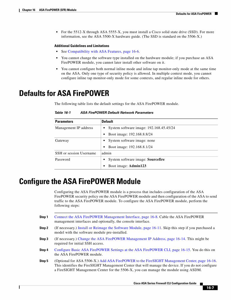
Defaults for ASA FirePOWERThe following table lists the default settings for the ASA FirePOWER module.
Configure the ASA FirePOWER ModuleConfiguring the ASA FirePOWER module is a process that includes configuration of the ASA FirePOWER security policy on the ASA FirePOWER module and then configuration of the ASA to send traffic to the ASA FirePOWER module. To configure the ASA FirePOWER module, perform the following steps:
Step 1 Connect the ASA FirePOWER Management Interface, page 16-8. Cable the ASA FirePOWER management interfaces and optionally, the console interface.
Step 2 (If necessary.) Install or Reimage the Software Module, page 16-11. Skip this step if you purchased a model with the software module pre-installed.
Step 3 (If necessary.) Change the ASA FirePOWER Management IP Address, page 16-14. This might be required for initial SSH access.
Step 4 Configure Basic ASA FirePOWER Settings at the ASA FirePOWER CLI, page 16-15. You do this on the ASA FirePOWER module.
Step 5 (Optional for ASA 5506-X.) Add ASA FirePOWER to the FireSIGHT Management Center, page 16-16. This identifies the FireSIGHT Management Center that will manage the device. If you do not configure a FireSIGHT Management Center for the 5506-X, you can manage the module using ASDM.
Table 16-1 ASA FirePOWER Default Network Parameters
Parameters Default
Management IP address • System software image: 192.168.45.45/24
• Boot image: 192.168.8.8/24
Gateway • System software image: none
• Boot image: 192.168.8.1/24
SSH or session Username admin
Password • System software image: Sourcefire
• Boot image: Admin123
16-7Cisco ASA Series Firewall CLI Configuration Guide

Chapter 16 ASA FirePOWER (SFR) Module Configure the ASA FirePOWER Module
Step 6 Configure the Security Policy on the ASA FirePOWER Module, page 16-17.
Step 7 Redirect Traffic to the ASA FirePOWER Module, page 16-19.
Connect the ASA FirePOWER Management InterfaceIn addition to providing management access to the ASA FirePOWER module, the ASA FirePOWER management interface needs access to an HTTP proxy server or a DNS server and the Internet for signature updates and more. This section describes recommended network configurations. Your network may differ.
ASA 5585-X (Hardware Module)
The ASA FirePOWER module includes a separate management and console interface from the ASA. For initial setup, you can connect with SSH to the ASA FirePOWER Management 1/0 interface using the default IP address. If you cannot use the default IP address, you can either use the console port or use ASDM to change the management IP address so you can use SSH. (See Change the ASA FirePOWER Management IP Address, page 16-14.)
If you have an inside router
If you have an inside router, you can route between the management network, which can include both the ASA Management 0/0 and ASA FirePOWER Management 1/0 interfaces, and the ASA inside network for Internet access. Be sure to also add a route on the ASA to reach the Management network through the inside router.
ASA 5585-X
PWRBOOT
ALARM
ACTVPN
PS1HDD1
PS0HDD0
USBRESET
0SFP1 SFP0 101234567 MGMT
0
1
AUX CONSOLE
PWRBOOT
ALARM
ACTVPN
PS1HDD1
PS0HDD0
USBRESET
0SFP1 SFP0 101234567 MGMT
0
1
AUX CONSOLE
ASA Management 0/0Default IP: 192.168.1.1
ASA FirePOWER Management 1/0
SSP
ASA FirePOWER SSP
3714
46
16-8Cisco ASA Series Firewall CLI Configuration Guide

Chapter 16 ASA FirePOWER (SFR) Module Configure the ASA FirePOWER Module
If you do not have an inside router
If you have only one inside network, then you cannot also have a separate management network, which would require an inside router to route between the networks. In this case, you can manage the ASA from the inside interface instead of the Management 0/0 interface. Because the ASA FirePOWER module is a separate device from the ASA, you can configure the ASA FirePOWER Management 1/0 address to be on the same network as the inside interface.
ASA 5506-X and 5512-X through ASA 5555-X (Software Module)
These models run the ASA FirePOWER module as a software module, and the ASA FirePOWER management interface shares the Management 0/0 interface with the ASA (Management 1/1 on 5506-X). For initial setup, you can connect with SSH to the ASA FirePOWER default IP address. If you cannot use the default IP address, you can either session to the ASA FirePOWER over the backplane or use ASDM to change the management IP address so you can use SSH.
ASA Management 0/0
Internet
Management PC
Proxy or DNS Server (for example)
RouterASA
ASA FirePOWER Management 1/0
Outside
FPManagement
InsideASA FirePOWERDefault Gateway
ASA gateway for Management
3714
47
Internet
Layer 2Switch ASA
Inside
ASA FirePOWER Management 1/0ASA Management 0/0 not used
Outside
FP
ASA FirePOWER Default Gateway
Management PC
Proxy or DNS Server(for example) 37
1448
ASA 5545-XASA FirePOWER Management 0/0
ASA Management 0/0Default IP: 192.168.1.1
3714
49
16-9Cisco ASA Series Firewall CLI Configuration Guide

Chapter 16 ASA FirePOWER (SFR) Module Configure the ASA FirePOWER Module
If you have an inside router
If you have an inside router, you can route between the Management 0/0 or 1/1 network, which includes both the ASA and ASA FirePOWER management IP addresses, and the inside network for Internet access. Be sure to also add a route on the ASA to reach the Management network through the inside router.
If you do not have an inside router
If you have only one inside network, then you cannot also have a separate management network. In this case, you can manage the ASA from the inside interface instead of the Management 0/0 or 1/1 interface. If you remove the ASA-configured name from the Management 0/0 or 1/1 interface, you can still configure the ASA FirePOWER IP address for that interface. Because the ASA FirePOWER module is essentially a separate device from the ASA, you can configure the ASA FirePOWER management address to be on the same network as the inside interface.
Note You must remove the ASA-configured name for Management 0/0 or 1/1; if it is configured on the ASA, then the ASA FirePOWER address must be on the same network as the ASA, and that excludes any networks already configured on other ASA interfaces. If the name is not configured, then the ASA FirePOWER address can be on any network, for example, the ASA inside network.
Internet
Management PC
Proxy or DNS Server (for example)
RouterASA
Management 0/0
Outside
FPManagement
InsideASA FirePOWER
Default Gateway
ASA gateway for Management
3714
50
Internet
Management PC
Layer 2Switch ASA
Inside
Management 0/0(ASA FirePOWER only)
Outside
FP
ASA FirePOWER Default Gateway
Proxy or DNS Server(for example) 37
1451
16-10Cisco ASA Series Firewall CLI Configuration Guide

Chapter 16 ASA FirePOWER (SFR) Module Configure the ASA FirePOWER Module
Install or Reimage the Software ModuleIf you purchase the ASA with the ASA FirePOWER module, the module software and required solid state drives (SSDs) come pre-installed and ready to configure. If you want to add the ASA FirePOWER software module to an existing ASA, or need to replace the SSD, you need to install the ASA FirePOWER boot software, partition the SSD, and install the system software according to this procedure.
Reimaging the module is the same procedure, except you should first uninstall the ASA FirePOWER module. You would reimage a system if you replace an SSD.
For information on how to physically install the SSD, see the ASA hardware guide.
Before You Begin
• The free space on flash (disk0) should be at least 3GB plus the size of the boot software.
• In multiple context mode, perform this procedure in the system execution space.
• You must shut down any other software module that you might be running; the device can run a single software module at a time. You must do this from the ASA CLI. For example, the following commands shut down and uninstall the IPS software module, and then reload the ASA; the commands to remove the CX module are the same, except use the cxsc keyword instead of ips.
hostname# sw-module module ips shutdownhostname# sw-module module ips uninstallhostname# reload
• If you have an active service policy redirecting traffic to an IPS or CX module, you must remove that policy. For example, if the policy is a global one, you could use no service-policy ips_policy global. If the service policy includes other rules you want to maintain, simply remove the redirection command from the relevant policy map, or the entire traffic class if redirection is the only action for the class. You can remove the policies using CLI or ASDM.
• When reimaging the module, use the same shutdown and uninstall commands to remove the old image. For example, sw-module module sfr uninstall.
• Obtain both the ASA FirePOWER Boot Image and System Software packages from Cisco.com.
Procedure
Step 1 Download the boot image to the device. Do not transfer the system software; it is downloaded later to the SSD. You have the following options:
• ASDM—First, download the boot image to your workstation, or place it on an FTP, TFTP, HTTP, HTTPS, SMB, or SCP server. Then, in ASDM, choose Tools > File Management, and then choose the appropriate File Transfer command, either Between Local PC and Flash or Between Remote Server and Flash. Transfer the boot software to disk0 on the ASA.
• ASA CLI—First, place the boot image on a TFTP, FTP, HTTP, or HTTPS server, then use the copy command to download it to flash. The following example uses TFTP; replace <TFTP Server> with your server’s IP address or host name.
ciscoasa# copy tftp://<TFTP SERVER>/asasfr-5500x-boot-5.3.1-58.img disk0:/asasfr-5500x-boot-5.3.1-58.img
Step 2 Download the ASA FirePOWER system software from Cisco.com to an HTTP, HTTPS, or FTP server accessible from the ASA FirePOWER management interface. Do not download it to disk0 on the ASA.
16-11Cisco ASA Series Firewall CLI Configuration Guide

Chapter 16 ASA FirePOWER (SFR) Module Configure the ASA FirePOWER Module
Step 3 Set the ASA FirePOWER module boot image location in ASA disk0 by entering the following command:
hostname# sw-module module sfr recover configure image disk0:file_path
If you get a message like “ERROR: Another service (cxsc) is running, only one service is allowed to run at any time,” it means that you already have a different software module configured. You must shut it down and remove it to install a new module as described in the prerequisites section above.
Example:
hostname# sw-module module sfr recover configure imagedisk0:asasfr-5500x-boot-5.3.1-58.img
Step 4 Load the ASA FirePOWER boot image by entering the following command:
hostname# sw-module module sfr recover boot
Step 5 Wait approximately 5-15 minutes for the ASA FirePOWER module to boot up, and then open a console session to the now-running ASA FirePOWER boot image. You might need to press enter after opening the session to get to the login prompt. The default username is admin and the default password is Admin123.
hostname# session sfr consoleOpening console session with module sfr.Connected to module sfr. Escape character sequence is 'CTRL-^X'.
Cisco ASA SFR Boot Image 5.3.1asasfr login: adminPassword: Admin123
If the module boot has not completed, the session command will fail with a message about not being able to connect over ttyS1. Wait and try again.
Step 6 Use the setup command to configure the system so that you can install the system software package.
asasfr-boot> setup
Welcome to SFR Setup [hit Ctrl-C to abort] Default values are inside []
You are prompted for the following. Note that the management address and gateway, and DNS information, are the key settings to configure.
• Host name—Up to 65 alphanumeric characters, no spaces. Hyphens are allowed.
• Network address—You can set static IPv4 or IPv6 addresses, or use DHCP (for IPv4) or IPv6 stateless autoconfiguration.
• DNS information—You must identify at least one DNS server, and you can also set the domain name and search domain.
• NTP information—You can enable NTP and configure the NTP servers, for setting system time.
Step 7 Install the System Software image using the system install command:
system install [noconfirm] url
Include the noconfirm option if you do not want to respond to confirmation messages. Use an HTTP, HTTPS, or FTP URL; if a username and password are required, you will be prompted to supply them.
When installation is complete, the system reboots. Allow 10 or more minutes for application component installation and for the ASA FirePOWER services to start. (The show module sfr output should show all processes as Up.)
16-12Cisco ASA Series Firewall CLI Configuration Guide

Chapter 16 ASA FirePOWER (SFR) Module Configure the ASA FirePOWER Module
For example:
asasfr-boot> system install http://upgrades.example.com/packages/asasfr-sys-5.3.1-44.pkg Verifying Downloading Extracting Package Detail Description: Cisco ASA-FirePOWER 5.3.1-44 System Install Requires reboot: Yes
Do you want to continue with upgrade? [y]: y Warning: Please do not interrupt the process or turn off the system.Doing so might leave system in unusable state.
Upgrading Starting upgrade process ... Populating new system image
Reboot is required to complete the upgrade. Press 'Enter' to reboot the system.(press Enter)Broadcast message from root (ttyS1) (Mon Feb 17 19:28:38 2014):
The system is going down for reboot NOW!Console session with module sfr terminated.
Step 8 Open a session to the ASA FirePOWER module. You will see a different login prompt because you are logging into the fully functional module.
asa3# session sfr console Opening console session with module sfr.Connected to module sfr. Escape character sequence is 'CTRL-^X'.
Sourcefire ASA5555 v5.3.1 (build 44)Sourcefire3D login:
Step 9 Log in with the username admin and the password Sourcefire.
Step 10 Complete the system configuration as prompted.
You must first read and accept the end user license agreement (EULA). Then change the admin password, then configure the management address and DNS settings, as prompted. You can configure both IPv4 and IPv6 management addresses. For example:
System initialization in progress. Please stand by. You must change the password for 'admin' to continue.Enter new password: <new password> Confirm new password: <repeat password> You must configure the network to continue.You must configure at least one of IPv4 or IPv6.Do you want to configure IPv4? (y/n) [y]: y Do you want to configure IPv6? (y/n) [n]: Configure IPv4 via DHCP or manually? (dhcp/manual) [manual]: Enter an IPv4 address for the management interface [192.168.45.45]: 10.86.118.3 Enter an IPv4 netmask for the management interface [255.255.255.0]: 255.255.252.0 Enter the IPv4 default gateway for the management interface []: 10.86.116.1 Enter a fully qualified hostname for this system [Sourcefire3D]: asasfr.example.com Enter a comma-separated list of DNS servers or 'none' []: 10.100.10.15, 10.120.10.14Enter a comma-separated list of search domains or 'none' [example.net]: example.com If your networking information has changed, you will need to reconnect.For HTTP Proxy configuration, run 'configure network http-proxy'(Wait for the system to reconfigure itself.)
This sensor must be managed by a Defense Center. A unique alphanumericregistration key is always required. In most cases, to register a sensor
16-13Cisco ASA Series Firewall CLI Configuration Guide

Chapter 16 ASA FirePOWER (SFR) Module Configure the ASA FirePOWER Module
to a Defense Center, you must provide the hostname or the IP address alongwith the registration key.'configure manager add [hostname | ip address ] [registration key ]'
However, if the sensor and the Defense Center are separated by a NAT device,you must enter a unique NAT ID, along with the unique registration key.'configure manager add DONTRESOLVE [registration key ] [ NAT ID ]'
Later, using the web interface on the Defense Center, you must use the sameregistration key and, if necessary, the same NAT ID when you add thissensor to the Defense Center.
Step 11 (Optional for 5506-X.) Identify the FireSIGHT Management Center appliance that will manage this device using the configure manager add command.
You come up with a registration key, which you will then use in FireSIGHT Management Center when you add the device to its inventory. The following example shows the simple case. When there is a NAT boundary, the command is different; see Add ASA FirePOWER to the FireSIGHT Management Center, page 16-16.
> configure manager add 10.89.133.202 123456 Manager successfully configured.
For the 5506-X, you can instead use ASDM to configure the policy on the ASA FirePOWER module. When using ASDM, you can configure one module at a time, which is a good solution when you have a single device or very few devices. If you have a large number of devices, FireSIGHT Management Center is a better solution.
Step 12 (Skip for 5506-X when using ASDM.) Log into the FireSIGHT Management Center using an HTTPS connection in a browser, using the hostname or address entered above. For example, https://DC.example.com.
Use the Device Management (Devices > Device Management) page to add the device. For more information, see the online help or the Managing Devices chapter in the FireSIGHT System User Guide.
Tip You also configure NTP and time settings through FireSIGHT Management Center. Use the Time Synchronization settings when editing the local policy from the System > Local > System Policy page.
Change the ASA FirePOWER Management IP AddressIf you cannot use the default management IP address, then you can set the management IP address from the ASA. After you set the management IP address, you can access the ASA FirePOWER module using SSH to perform additional setup.
If you already configured the management address during initial system setup through the ASA FirePOWER CLI, as described in Configure Basic ASA FirePOWER Settings at the ASA FirePOWER CLI, page 16-15, then it is not necessary to configure it through the ASA CLI or ASDM.
Note For a software module, you can access the ASA FirePOWER CLI to perform setup by sessioning from the ASA CLI; you can then set the ASA FirePOWER management IP address as part of setup. For a hardware module, you can complete the initial setup through the Console port.
16-14Cisco ASA Series Firewall CLI Configuration Guide
Chapter 16 ASA FirePOWER (SFR) Module Configure the ASA FirePOWER Module
To change the management IP address through the ASA, do one of the following. In multiple context mode, perform this procedure in the system execution space.
• In the CLI, use the following command to set the ASA FirePOWER management IP address, mask, and gateway. Use 1 for a hardware module, sfr for a software module.
session {1 | sfr} do setup host ip ip_address/mask,gateway_ip
For example, session 1 do setup host ip 10.1.1.2/24,10.1.1.1.
• In ASDM, choose Wizards > Startup Wizard, and progress through the wizard to the ASA FirePOWER Basic Configuration, where you can set the IP address, mask, and default gateway.
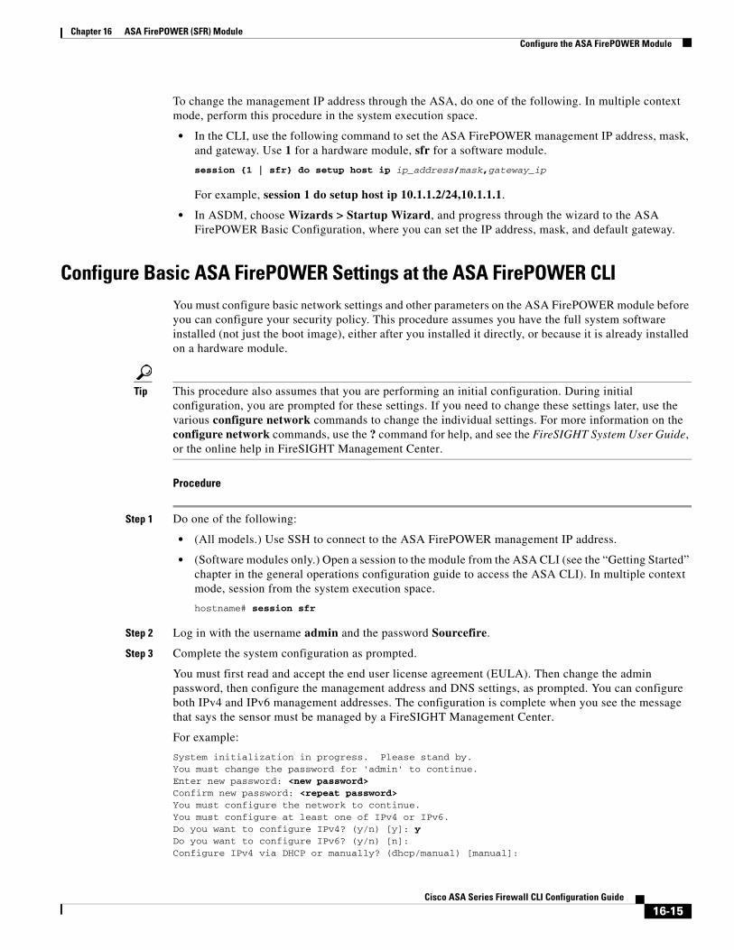
Configure Basic ASA FirePOWER Settings at the ASA FirePOWER CLIYou must configure basic network settings and other parameters on the ASA FirePOWER module before you can configure your security policy. This procedure assumes you have the full system software installed (not just the boot image), either after you installed it directly, or because it is already installed on a hardware module.
Tip This procedure also assumes that you are performing an initial configuration. During initial configuration, you are prompted for these settings. If you need to change these settings later, use the various configure network commands to change the individual settings. For more information on the configure network commands, use the ? command for help, and see the FireSIGHT System User Guide, or the online help in FireSIGHT Management Center.
Procedure
Step 1 Do one of the following:
• (All models.) Use SSH to connect to the ASA FirePOWER management IP address.
• (Software modules only.) Open a session to the module from the ASA CLI (see the “Getting Started” chapter in the general operations configuration guide to access the ASA CLI). In multiple context mode, session from the system execution space.
hostname# session sfr
Step 2 Log in with the username admin and the password Sourcefire.
Step 3 Complete the system configuration as prompted.
You must first read and accept the end user license agreement (EULA). Then change the admin password, then configure the management address and DNS settings, as prompted. You can configure both IPv4 and IPv6 management addresses. The configuration is complete when you see the message that says the sensor must be managed by a FireSIGHT Management Center.
For example:
System initialization in progress. Please stand by. You must change the password for 'admin' to continue.Enter new password: <new password> Confirm new password: <repeat password> You must configure the network to continue.You must configure at least one of IPv4 or IPv6.Do you want to configure IPv4? (y/n) [y]: y Do you want to configure IPv6? (y/n) [n]: Configure IPv4 via DHCP or manually? (dhcp/manual) [manual]:
16-15Cisco ASA Series Firewall CLI Configuration Guide

Chapter 16 ASA FirePOWER (SFR) Module Configure the ASA FirePOWER Module
Enter an IPv4 address for the management interface [192.168.45.45]: 10.86.118.3 Enter an IPv4 netmask for the management interface [255.255.255.0]: 255.255.252.0 Enter the IPv4 default gateway for the management interface []: 10.86.116.1 Enter a fully qualified hostname for this system [Sourcefire3D]: asasfr.example.com Enter a comma-separated list of DNS servers or 'none' []: 10.100.10.15, 10.120.10.14Enter a comma-separated list of search domains or 'none' [example.net]: example.com If your networking information has changed, you will need to reconnect.For HTTP Proxy configuration, run 'configure network http-proxy'(Wait for the system to reconfigure itself.)
This sensor must be managed by a Defense Center. A unique alphanumericregistration key is always required. In most cases, to register a sensorto a Defense Center, you must provide the hostname or the IP address alongwith the registration key.'configure manager add [hostname | ip address ] [registration key ]'
However, if the sensor and the Defense Center are separated by a NAT device,you must enter a unique NAT ID, along with the unique registration key.'configure manager add DONTRESOLVE [registration key ] [ NAT ID ]'
Later, using the web interface on the Defense Center, you must use the sameregistration key and, if necessary, the same NAT ID when you add thissensor to the Defense Center.
Step 4 (Optional for 5506-X.) Now you must identify the FireSIGHT Management Center that will manage this device, as explained in Add ASA FirePOWER to the FireSIGHT Management Center, page 16-16.
Add ASA FirePOWER to the FireSIGHT Management CenterFireSIGHT Management Center, also known as Defense Center, is a separate server that manages multiple FirePOWER devices for the same or different models. FireSIGHT Management Center is ideal for managing large deployments, providing configuration consistency across your devices and efficiency in traffic analysis.
For ASA 5512-X through 5585-X, you must register the module to a FireSIGHT Management Center. There is no other way to configure the module.
For ASA 5506-X, FireSIGHT Management Center is optional. If you do not configure one, you use ASDM to configure the ASA FirePOWER policy. There is no CLI for policy configuration, you must use ASDM or FireSIGHT Management Center.
To register a device, use the configure manager add command. A unique alphanumeric registration key is always required to register a device to a FireSIGHT Management Center. This is a simple key that you specify, and is not the same as a license key.
In most cases, you must provide the FireSIGHT Management Center’s hostname or the IP address along with the registration key, for example:
configure manager add DC.example.com my_reg_key
However, if the device and the FireSIGHT Management Center are separated by a NAT device, enter a unique NAT ID along with the registration key, and specify DONTRESOLVE instead of the hostname, for example:
configure manager add DONTRESOLVE my_reg_key my_nat_id
16-16Cisco ASA Series Firewall CLI Configuration Guide

Chapter 16 ASA FirePOWER (SFR) Module Configure the ASA FirePOWER Module
Procedure
Step 1 Do one of the following:
• (All models.) Use SSH to connect to the ASA FirePOWER management IP address.
• (Software modules only.) Open a session to the module from the ASA CLI (see the “Getting Started” chapter in the general operations configuration guide to access the ASA CLI). In multiple context mode, session from the system execution space.
hostname# session sfr
Step 2 Log in with the username admin or another username that has the CLI configuration (Administrator) access level.
Step 3 At the prompt, register the device to a FireSIGHT Management Center using the configure manager add command, which has the following syntax:
configure manager add {hostname | IPv4_address | IPv6_address | DONTRESOLVE} reg_key [nat_id]
where:
• {hostname | IPv4_address | IPv6_address | DONTRESOLVE} specifies either the fully qualified host name or IP address of the FireSIGHT Management Center. If the FireSIGHT Management Center is not directly addressable, use DONTRESOLVE.
• reg_key is the unique alphanumeric registration key required to register a device to the FireSIGHT Management Center.
• nat_id is an optional alphanumeric string used during the registration process between the FireSIGHT Management Center and the device. It is required if the hostname is set to DONTRESOLVE.
Step 4 Log into the FireSIGHT Management Center using an HTTPS connection in a browser, using the hostname or address entered above. For example, https://DC.example.com.
Use the Device Management (Devices > Device Management) page to add the device. For more information, see the online help or the Managing Devices chapter in the FireSIGHT System User Guide.
Configure the Security Policy on the ASA FirePOWER ModuleThe security policy controls the services provided by the module, such as Next Generation IPS filtering and application filtering.
You use FireSIGHT Management Center to configure the security policy on the module.
For the ASA 5506-X, you can alternatively use ASDM. However, you can never use both ASDM and FireSIGHT Management Center, you must choose one or the other. If you configure a FireSIGHT Management Center for the module, you must use the configured manager. If you do not configure a manager, you must use ASDM.
There is no CLI for configuring the security policy.
16-17Cisco ASA Series Firewall CLI Configuration Guide
Chapter 16 ASA FirePOWER (SFR) Module Configure the ASA FirePOWER Module
Configure the Security Policy with FireSIGHT Management Center
To open FireSIGHT Management Center, do one of the following:
• Use a web browser to open https://DC_address, where DC_address is the DNS name or IP address of the manager you defined in Add ASA FirePOWER to the FireSIGHT Management Center, page 16-16. For example, https://dc.example.com.
• In ASDM, choose Home > ASA FirePOWER Status and click the link at the bottom of the dashboard.
For information about how to configure the security policy, see the FireSIGHT System User Guide or the online help in FireSIGHT Management Center.
Configure the Security Policy with ASDM
For ASA 5506-X, if you do not configure a FireSIGHT Management Center, you use ASDM to configure the security policy.
ASA FirePOWER pages are separate from the ASA configuration pages. Use the following pages to monitor and configure the module. You can click Help in any page, or choose Help > ASA FirePOWER Help Topics, to learn more about how to configure policies.
• Home > ASA FirePOWER Dashboard—The dashboard provides summary information about the software running on the module, product updates, licensing, system load, disk usage, system time, and interface status.
• Home > ASA FirePOWER Reporting—The reporting page provides Top 10 dashboards for a wide variety of module statistics, such as web categories, users, sources, and destinations for the traffic passing through the module.
• Home > ASA FirePOWER Status—Also available when you manage the module with FireSIGHT Management Center, the status page includes module information, such as the model, serial number, and software version, and module status, such as the application name and status, data plane status, and overall status. If the module is registered to a FireSIGHT Management Center, you can click the link to open the application and do further analysis and module configuration.
• Configuration > ASA FirePOWER Configuration—This drawer includes pages for each ASA FirePOWER policy, such as access control and intrusion policies. The configuration of these policies is consistent with the same policies in FireSIGHT Management Center, so you can easily transition between the two products. Click Help within the policy page to get detailed information on configuring the policies.
• Configuration > Firewall > Access Rules—When you choose to configure ASA FirePOWER with ASDM, the ASA access rules page includes toggle buttons so that you can easily switch the view between ASA rules and ASA FirePOWER rules. Keep in mind that ASA inbound rules on an interface are always applied before ASA FirePOWER access control policies. Any traffic dropped through inbound rules is never sent to ASA FirePOWER.
• Monitoring > ASA FirePOWER Monitoring—There are several pages for monitoring the module, including syslog, task status, module statistics, and a real-time event viewer.
16-18Cisco ASA Series Firewall CLI Configuration Guide
Chapter 16 ASA FirePOWER (SFR) Module Configure the ASA FirePOWER Module
ASDM Restrictions for Managing ASA FirePOWER
Keep the following restrictions in mind when configuring ASA FirePOWER using ASDM.
• If you enable command authorization on the ASA that hosts the module, you must log in with a user name that has privilege level 15 to see the ASA FirePOWER home, configuration, and monitoring pages. Read-only or monitor-only access to ASA FirePOWER pages other than the status page is not supported.
• If you configure the ASA in a failover pair, the ASA FirePOWER configuration is not automatically synchronized with the ASA FirePOWER module on the secondary device. Thus, you must manually export the ASA FirePOWER configuration from the primary and import it into the secondary every time you make a change. We recommend using FireSIGHT Management Center for any device configured for failover.
• If you are using Java 7_u51 up to Java 8, you need to import the SSL certificate from the ASA FirePOWER module to your workstation to view the configuration pages. Go to Wizard > ASDM Identity Certificate Wizard to obtain the certificate. Then, go to your Java Control Panel and import it, and restart ASDM. This is a general issue with these Java versions, and you will also need to import the certificate from the ASA to configure it through ASDM.
Redirect Traffic to the ASA FirePOWER ModuleFor inline and inline tap (monitor-only) modes, you configure a service policy to redirect traffic to the module. If you want passive monitor-only mode, you configure a traffic redirection interface, which bypasses ASA policies.
The following topics explain how to configure these modes.
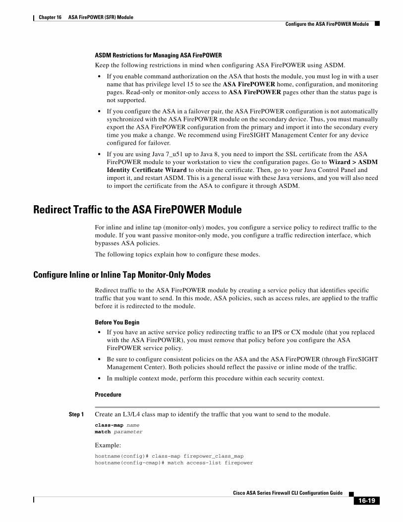
Configure Inline or Inline Tap Monitor-Only Modes
Redirect traffic to the ASA FirePOWER module by creating a service policy that identifies specific traffic that you want to send. In this mode, ASA policies, such as access rules, are applied to the traffic before it is redirected to the module.
Before You Begin
• If you have an active service policy redirecting traffic to an IPS or CX module (that you replaced with the ASA FirePOWER), you must remove that policy before you configure the ASA FirePOWER service policy.
• Be sure to configure consistent policies on the ASA and the ASA FirePOWER (through FireSIGHT Management Center). Both policies should reflect the passive or inline mode of the traffic.
• In multiple context mode, perform this procedure within each security context.
Procedure
Step 1 Create an L3/L4 class map to identify the traffic that you want to send to the module.
class-map name match parameter
Example:
hostname(config)# class-map firepower_class_maphostname(config-cmap)# match access-list firepower
16-19Cisco ASA Series Firewall CLI Configuration Guide

Chapter 16 ASA FirePOWER (SFR) Module Configure the ASA FirePOWER Module
If you want to send multiple traffic classes to the module, you can create multiple class maps for use in the security policy. For information on matching statements, see Identify Traffic (Layer 3/4 Class Maps), page 1-13.
Step 2 Add or edit a policy map that sets the actions to take with the class map traffic.
policy-map name
Example:
hostname(config)# policy-map global_policy
In the default configuration, the global_policy policy map is assigned globally to all interfaces. If you want to edit the global_policy, enter global_policy as the policy name.
Step 3 Identify the class map you created at the start of this procedure.
class name
Example:
hostname(config-pmap)# class firepower_class_map
Step 4 Send the traffic to the ASA FirePOWER module.
sfr {fail-close | fail-open} [monitor-only]
Where:
• The fail-close keyword sets the ASA to block all traffic if the ASA FirePOWER module is unavailable.
• The fail-open keyword sets the ASA to allow all traffic through, uninspected, if the module is unavailable.
• Specify monitor-only to send a read-only copy of traffic to the module, i.e. inline tap mode. If you do not include the keyword, the traffic is sent in inline mode. Be sure to configure consistent policies on the ASA and the ASA FirePOWER. See ASA FirePOWER Inline Tap Monitor-Only Mode, page 16-3 for more information.
Example:
hostname(config-pmap-c)# sfr fail-close
Step 5 If you created multiple class maps for ASA FirePOWER traffic, you can specify another class for the policy and apply the sfr redirect action.
See Feature Matching Within a Service Policy, page 1-5 for detailed information about how the order of classes matters within a policy map. Traffic cannot match more than one class map for the same action type.
Step 6 If you are editing an existing service policy (such as the default global policy called global_policy), you are done. Otherwise, activate the policy map on one or more interfaces.
service-policy policymap_name {global | interface interface_name}
Example:
hostname(config)# service-policy global_policy global
The global keyword applies the policy map to all interfaces, and interface applies the policy to one interface. Only one global policy is allowed. You can override the global policy on an interface by applying a service policy to that interface. You can only apply one policy map to each interface.
16-20Cisco ASA Series Firewall CLI Configuration Guide

Chapter 16 ASA FirePOWER (SFR) Module Configure the ASA FirePOWER Module
Configure Passive Traffic Forwarding
If you want to operate the module in passive monitor-only mode, where the module gets a copy of the traffic and neither it nor the ASA can affect the network, configure a traffic forwarding interface and connect the interface to a SPAN port on a switch. For more details, see ASA FirePOWER Passive Monitor-Only Traffic Forwarding Mode, page 16-4.
The following guidelines explain the requirements for this deployment mode:
• The ASA must be in single-context and transparent mode.
• You can configure up to 4 interfaces as traffic-forwarding interfaces. Other ASA interfaces can be used as normal.
• Traffic-forwarding interfaces must be physical interfaces, not VLANs or BVIs. The physical interface also cannot have any VLANs associated with it.
• Traffic-forwarding interfaces cannot be used for ASA traffic; you cannot name them or configure them for ASA features, including failover or management-only.
• You cannot configure both a traffic-forwarding interface and a service policy for ASA FirePOWER traffic.
Procedure
Step 1 Enter interface configuration mode for the physical interface you want to use for traffic-forwarding.
interface physical_interface
Example:
hostname(config)# interface gigabitethernet 0/5
Step 2 Remove any name configured for the interface. If this interface was used in any ASA configuration, that configuration is removed. You cannot configure traffic-forwarding on a named interface.
no nameif
Step 3 Enable traffic-forwarding.
traffic-forward sfr monitor-only
Note You can ignore any warnings about traffic forwarding being for demonstration purposes only. This is a supported production mode.
Step 4 Enable the interface.
no shutdown
Repeat for any additional interfaces.
Examples
The following example makes GigabitEthernet 0/5 a traffic-forwarding interface:
interface gigabitethernet 0/5no nameiftraffic-forward sfr monitor-onlyno shutdown
16-21Cisco ASA Series Firewall CLI Configuration Guide

Chapter 16 ASA FirePOWER (SFR) Module Managing the ASA FirePOWER Module
Managing the ASA FirePOWER ModuleThis section includes procedures that help you manage the module.
• Reset the Password, page 16-22
• Reload or Reset the Module, page 16-22
• Shut Down the Module, page 16-23
• Uninstall a Software Module Image, page 16-23
• Session to the Software Module From the ASA, page 16-23
• Reimage the 5585-X ASA FirePOWER Hardware Module, page 16-24
• Upgrade the System Software, page 16-26
Reset the PasswordIf you forget the password for the admin user, another user with CLI Configuration permissions can log in and change the password.
If there are no other users with the required permissions, you can reset the admin password from the ASA using the session do command.
Tip The password-reset option on the ASA hw-module and sw-module commands does not work with ASA FirePOWER.
To reset the module password for the user admin to the default, Sourcefire, use the following command. Use 1 for a hardware module, sfr for a software module. In multiple context mode, perform this procedure in the system execution space.
session {1 | sfr} do password-reset
For example, session sfr do password-reset.
Reload or Reset the ModuleTo reload, or to reset and then reload, the module, enter one of the following commands at the ASA CLI. In multiple context mode, perform this procedure in the system execution space.
• Hardware module (ASA 5585-X):
hw-module module 1 {reload | reset}
• Software module (all other models):
sw-module module sfr {reload | reset}
16-22Cisco ASA Series Firewall CLI Configuration Guide

Chapter 16 ASA FirePOWER (SFR) Module Managing the ASA FirePOWER Module
Shut Down the ModuleShutting down the module software prepares the module to be safely powered off without losing configuration data. To gracefully shut down the module, enter one of the following commands at the ASA CLI. In multiple context mode, perform this procedure in the system execution space.
Note If you reload the ASA, the module is not automatically shut down, so we recommend shutting down the module before reloading the ASA.
• Hardware module (ASA 5585-X):
hw-module module 1 shutdown
• Software module (all other models):
sw-module module sfr shutdown
Uninstall a Software Module ImageYou can uninstall a software module image and its associated configuration. In multiple context mode, perform this procedure in the system execution space.
Procedure
Step 1 Uninstall the software module image and associated configuration.
hostname# sw-module module sfr uninstall
Module sfr will be uninstalled. This will completely remove the disk image associated with the sw-module including any configuration that existed within it.
Uninstall module sfr? [confirm]
Step 2 Reload the ASA. You must reload the ASA before you can install a new module.
hostname# reload
Session to the Software Module From the ASAUse the ASA FirePOWER CLI to configure basic network settings and to troubleshoot the module.
To access the ASA FirePOWER software module CLI from the ASA, you can session from the ASA. (You cannot session to a hardware module running on a 5585-X.)
You can either session to the module (using Telnet) or create a virtual console session. A console session might be useful if the control plane is down and you cannot establish a Telnet session. In multiple context mode, session from the system execution space.
16-23Cisco ASA Series Firewall CLI Configuration Guide

Chapter 16 ASA FirePOWER (SFR) Module Managing the ASA FirePOWER Module
In either a Telnet or a Console session, you are prompted for a username and password. You can log in with any username configured on the ASA FirePOWER. Initially, the admin username is the only one configured (and it is always available). The initial default password is Sourcefire for the full image, and Admin123 for the boot image.
• Telnet session:
session sfr
When in the ASA FirePOWER CLI, to exit back to the ASA CLI, enter any command that would log you out of the module, such as logout or exit, or press Ctrl-Shift-6, x.
• Console session:
session sfr console
The only way out of a console session is to press Ctrl-Shift-6, x. Logging out of the module leaves you at the module login prompt.
Note Do not use the session sfr console command in conjunction with a terminal server where Ctrl-Shift-6, x is the escape sequence to return to the terminal server prompt. Ctrl-Shift-6, x is also the sequence to escape the ASA FirePOWER console and return to the ASA prompt. Therefore, if you try to exit the ASA FirePOWER console in this situation, you instead exit all the way to the terminal server prompt. If you reconnect the terminal server to the ASA, the ASA FirePOWER console session is still active; you can never exit to the ASA prompt. You must use a direct serial connection to return the console to the ASA prompt. Use the session sfr command instead of the console command when facing this situation.
Reimage the 5585-X ASA FirePOWER Hardware ModuleIf you need to reimage the ASA FirePOWER hardware module in an ASA 5585-X appliance for any reason, you need to install both the Boot Image and a System Software package, in that order. You must install both packages to have a functioning system. Under normal circumstances, you do not need to reimage the system to install upgrade packages.
To install the boot image, you need to TFTP boot the image from the Management-0 port on the ASA FirePOWER SSP by logging into the module’s Console port. Because the Management-0 port is on an SSP in the first slot, it is also known as Management1/0, but rommon recognizes it as Management-0 or Management0/1.
To accomplish a TFTP boot, you must:
• Place the software image on a TFTP server that can be accessed through the Management1/0 interface on the ASA FirePOWER.
• Connect Management1/0 to the network. You must use this interface to TFTP boot the Boot Image.
• Configure rommon variables. Press Esc to interrupt the auto-boot process so that you can configure rommon variables.
Once the boot image is installed, you install the System Software package. You must place the package on an HTTP, HTTPS, or FTP server that is accessible from the ASA FirePOWER.
The following procedure explains how to install the boot image and then install the System Software package.
16-24Cisco ASA Series Firewall CLI Configuration Guide

Chapter 16 ASA FirePOWER (SFR) Module Managing the ASA FirePOWER Module
Procedure
Step 1 Connect to the Console port. Use the console cable included with the ASA product to connect your PC to the console using a terminal emulator set for 9600 baud, 8 data bits, no parity, 1 stop bit, no flow control. See the hardware guide for your ASA for more information about the console cable.
Step 2 Enter the system reboot command to reload the system.
Step 3 When prompted, break out of the boot by pressing Esc. If you see grub start to boot the system, you have waited too long.
This will place you at the rommon prompt.
Step 4 At the rommon prompt, enter set and configure the following parameters:
• ADDRESS—The management IP address of the module.
• SERVER—The IP address of the TFTP server.
• GATEWAY—The gateway address to the TFTP server. If the TFTP server is directly attached to Management1/0, use the IP address of the TFTP server. If the TFTP server and management address are on the same subnet, do not configure the gateway or TFTP boot will fail.
• IMAGE—The Boot Image path and image name on the TFTP server. For example, if you place the file on the TFTP server in /tftpboot/images/filename.img, the IMAGE value is images/filename.img.
For example:
ADDRESS=10.5.190.199 SERVER=10.5.11.170 GATEWAY=10.5.1.1 IMAGE=asasfr-boot-5.3.1-26-54.img
Step 5 Enter sync to save the settings.
Step 6 Enter tftp to initiate the download and boot process.
You will see ! marks to indicate progress. When the boot completes after several minutes, you will see a login prompt.
Step 7 Log in as admin, with the password Admin123.
Step 8 Use the setup command to configure the system so that you can install the system software package.
You are prompted for the following. Note that the management address and gateway, and DNS information, are the key settings to configure.
• Host name—Up to 65 alphanumeric characters, no spaces. Hyphens are allowed.
• Network address—You can set static IPv4 or IPv6 addresses, or use DHCP (for IPv4) or IPv6 stateless autoconfiguration.
• DNS information—You must identify at least one DNS server, and you can also set the domain name and search domain.
• NTP information—You can enable NTP and configure the NTP servers, for setting system time.
Step 9 Install the System Software image using the system install command:
system install [noconfirm] url
Include the noconfirm option if you do not want to respond to confirmation messages.
When installation is complete, the system reboots. Allow 10 or more minutes for application component installation and for the ASA FirePOWER services to start.
16-25Cisco ASA Series Firewall CLI Configuration Guide

Chapter 16 ASA FirePOWER (SFR) Module Monitoring the ASA FirePOWER Module
For example:
asasfr-boot> system install http://upgrades.example.com/packages/asasfr-sys-5.3.1-54.pkg
Step 10 When the boot completes, log in as admin with the password Sourcefire.
Complete the system configuration as prompted.
You must first read and accept the end user license agreement (EULA). Then change the admin password, then configure the management address and DNS settings, as prompted. You can configure both IPv4 and IPv6 management addresses.
Step 11 Identify the FireSIGHT Management Center appliance that will manage this device using the configure manager add command.
You come up with a registration key, which you will then use in FireSIGHT Management Center when you add the device to its inventory. The following example shows the simple case. When there is a NAT boundary, the command is different; see Add ASA FirePOWER to the FireSIGHT Management Center, page 16-16.
> configure manager add 10.89.133.202 123456 Manager successfully configured.
Step 12 Log into the FireSIGHT Management Center using an HTTPS connection in a browser, using the hostname or address entered above. For example, https://DC.example.com.
Use the Device Management (Devices > Device Management) page to add the device. For more information, see the Managing Devices chapter in the FireSIGHT System User Guide or the online help in FireSIGHT Management Center.
Upgrade the System SoftwareUse FireSIGHT Management Center to apply upgrade images to the ASA FirePOWER module. Before applying an upgrade, ensure that the ASA is running the minimum required release for the new version; you might need to upgrade the ASA prior to upgrading the module. For more information about applying upgrades, see the FireSIGHT System User Guide or the online help in FireSIGHT Management Center.
If you are managing the module through ASDM, you can apply upgrades to the system software and components using Configuration > ASA FirePOWER Configuration > Updates. Click Help on the Updates page for more information.
Monitoring the ASA FirePOWER ModuleThe following topics provide guidance on monitoring the module. For ASA FirePOWER-related syslog messages, see the syslog messages guide. ASA FirePOWER syslog messages start with message number 434001.
• Showing Module Status, page 16-27
• Showing Module Statistics, page 16-28
• Monitoring Module Connections, page 16-28
16-26Cisco ASA Series Firewall CLI Configuration Guide

Chapter 16 ASA FirePOWER (SFR) Module Monitoring the ASA FirePOWER Module
Showing Module StatusTo check the status of a module, enter one of the following commands:
• show module [1 | sfr] [details]
Shows the status of modules. Include the 1 (for hardware modules) or sfr (for software modules) keyword to see status specific to the ASA FirePOWER module. Include the details keyword to get additional information, including the address of the device that manages the module.
• show module sfr recover
Displays the location of the boot image used when installing the module.
The following is sample output from the show module command for an ASA 5585-X with an ASA FirePOWER hardware module installed:
hostname# show moduleMod Card Type Model Serial No. ---- -------------------------------------------- ------------------ ----------- 0 ASA 5585-X Security Services Processor-10 wi ASA5585-SSP-10 JAF1507AMKE 1 ASA 5585-X FirePOWER Security Services Proce ASA5585-SSP-SFR10 JAF1510BLSA
Mod MAC Address Range Hw Version Fw Version Sw Version ---- --------------------------------- ------------ ------------ --------------- 0 5475.d05b.1100 to 5475.d05b.110b 1.0 2.0(7)0 100.10(0)8 1 5475.d05b.2450 to 5475.d05b.245b 1.0 2.0(13)0 5.3.1-44
Mod SSM Application Name Status SSM Application Version---- ------------------------------ ---------------- --------------------------
1 FirePOWER Up 5.3.1-44
Mod Status Data Plane Status Compatibility---- ------------------ --------------------- ------------- 0 Up Sys Not Applicable 1 Up Up
The following example shows the details for a software module. Note that DC Addr indicates the address of the FireSIGHT Management Center that manages this device.
hostname# show module sfr details Getting details from the Service Module, please wait...
Card Type: FirePOWER Services Software ModuleModel: ASA5555Hardware version: N/ASerial Number: FCH1714J6HPFirmware version: N/ASoftware version: 5.3.1-100MAC Address Range: bc16.6520.1dcb to bc16.6520.1dcbApp. name: ASA FirePOWERApp. Status: UpApp. Status Desc: Normal OperationApp. version: 5.3.1-100Data Plane Status: UpStatus: UpDC addr: 10.89.133.202 Mgmt IP addr: 10.86.118.7 Mgmt Network mask: 255.255.252.0 Mgmt Gateway: 10.86.116.1 Mgmt web ports: 443 Mgmt TLS enabled: true
16-27Cisco ASA Series Firewall CLI Configuration Guide

Chapter 16 ASA FirePOWER (SFR) Module Monitoring the ASA FirePOWER Module
The following example shows the location of the ASA FirePOWER boot image that was used with the sw-module module sfr recover command when installing the module.
hostname# show module sfr recover Module sfr recover parameters...Boot Recovery Image: NoImage File Path: disk0:/asasfr-5500x-boot-5.3.1-44.img
Showing Module StatisticsUse the show service-policy sfr command to display statistics and status for each service policy that includes the sfr command. Use clear service-policy to clear the counters.
The following example shows the ASA FirePOWER service policy and the current statistics as well as the module status. In monitor-only mode, the input counters remain at zero.
ciscoasa# show service-policy sfr
Global policy: Service-policy: global_policy Class-map: my-sfr-class SFR: card status Up, mode fail-close
packet input 2626422041, packet output 2626877967, drop 0, reset-drop 0, proxied 0
Monitoring Module ConnectionsTo show connections through the ASA FirePOWER module, enter one of the following commands:
• show asp table classify domain sfr
Shows the NP rules created to send traffic to the ASA FirePOWER module.
• show asp drop
Shows dropped packets. The drop types are explained below.
• show conn
Shows if a connection is being forwarded to a module by displaying the ‘X - inspected by service module’ flag.
The show asp drop command can include the following drop reasons related to the ASA FirePOWER module.
Frame Drops:
• sfr-bad-tlv-received—This occurs when ASA receives a packet from FirePOWER without a Policy ID TLV. This TLV must be present in non-control packets if it does not have the Standby/Active bit set in the actions field.
• sfr-request—The frame was requested to be dropped by FirePOWER due a policy on FirePOWER whereby FirePOWER would set the actions to Deny Source, Deny Destination, or Deny Pkt. If the frame should not have been dropped, review the policies on the module that are denying the flow.
• sfr-fail-close—The packet is dropped because the card is not up and the policy configured was ‘fail-close’ (rather than ‘fail-open’ which allows packets through even if the card was down). Check card status and attempt to restart services or reboot it.
16-28Cisco ASA Series Firewall CLI Configuration Guide

Chapter 16 ASA FirePOWER (SFR) Module Examples for the ASA FirePOWER Module
• sfr-fail—The FirePOWER configuration was removed for an existing flow and we are not able to process it through FirePOWER it will be dropped. This should be very unlikely.
• sfr-malformed-packet—The packet from FirePOWER contains an invalid header. For instance, the header length may not be correct.
• sfr-ha-request—This counter is incremented when the security appliance receives a FirePOWER HA request packet, but could not process it and the packet is dropped.
• sfr-invalid-encap—This counter is incremented when the security appliance receives a FirePOWER packet with invalid message header, and the packet is dropped.
• sfr-bad-handle-received—Received Bad flow handle in a packet from FirePOWER Module, thus dropping flow. This counter is incremented, flow and packet are dropped on ASA as the handle for FirePOWER flow has changed in flow duration.
• sfr-rx-monitor-only—This counter is incremented when the security appliance receives a FirePOWER packet when in monitor-only mode, and the packet is dropped.
Flow Drops:
• sfr-request—The FirePOWER requested to terminate the flow. The actions bit 0 is set.
• reset-by-sfr—The FirePOWER requested to terminate and reset the flow. The actions bit 1 is set.
• sfr-fail-close—The flow was terminated because the card is down and the configured policy was 'fail-close'.
Examples for the ASA FirePOWER ModuleThe following example diverts all HTTP traffic to the ASA FirePOWER module, and blocks all HTTP traffic if the module fails for any reason:
hostname(config)# access-list ASASFR permit tcp any any eq 80hostname(config)# class-map my-sfr-classhostname(config-cmap)# match access-list ASASFRhostname(config-cmap)# policy-map my-sfr-policyhostname(config-pmap)# class my-sfr-classhostname(config-pmap-c)# sfr fail-closehostname(config-pmap-c)# service-policy my-sfr-policy global
The following example diverts all IP traffic destined for the 10.1.1.0 network and the 10.2.1.0 network to the ASA FirePOWER module, and allows all traffic through if the module fails for any reason.
hostname(config)# access-list my-sfr-acl permit ip any 10.1.1.0 255.255.255.0hostname(config)# access-list my-sfr-acl2 permit ip any 10.2.1.0 255.255.255.0hostname(config)# class-map my-sfr-classhostname(config-cmap)# match access-list my-sfr-aclhostname(config)# class-map my-sfr-class2hostname(config-cmap)# match access-list my-sfr-acl2hostname(config-cmap)# policy-map my-sfr-policyhostname(config-pmap)# class my-sfr-classhostname(config-pmap-c)# sfr fail-openhostname(config-pmap)# class my-sfr-class2hostname(config-pmap-c)# sfr fail-openhostname(config-pmap-c)# service-policy my-sfr-policy interface outside
16-29Cisco ASA Series Firewall CLI Configuration Guide

Chapter 16 ASA FirePOWER (SFR) Module History for the ASA FirePOWER Module
History for the ASA FirePOWER Module
FeaturePlatform Releases Description
ASA 5585-X (all models) support for the matching ASA FirePOWER SSP hardware module.
ASA 5512-X through ASA 5555-X support for the ASA FirePOWER software module.
ASA 9.2(2.4)
ASA FirePOWER 5.3.1
The ASA FirePOWER module supplies next-generation firewall services, including Next-Generation IPS (NGIPS), Application Visibility and Control (AVC), URL filtering, and Advanced Malware Protection (AMP).You can use the module in single or multiple context mode, and in routed or transparent mode.
We introduced or modified the following commands: capture interface asa_dataplane, debug sfr, hw-module module 1 reload, hw-module module 1 reset, hw-module module 1 shutdown, session do setup host ip, session do get-config, session do password-reset, session sfr, sfr, show asp table classify domain sfr, show capture, show conn, show module sfr, show service-policy, sw-module sfr.
ASA 5506-X support for the ASA FirePOWER software module, including support for configuring the module in ASDM
ASA 9.3(2)
ASA FirePOWER 5.4.1
You can run the ASA FirePOWER software module on the ASA 5506-X. You can manage the module using FireSIGHT Management Center, or you can use ASDM.
ASA FirePOWER passive monitor-only mode using traffic redirection interfaces
ASA 9.3(2)
ASA FirePOWER 5.4.1
You can now configure a traffic forwarding interface to send traffic to the module instead of using a service policy. In this mode, neither the module nor the ASA affects the traffic.
We fully supported the following command: traffic-forward sfr monitor-only. You can configure this in CLI only.
16-30Cisco ASA Series Firewall CLI Configuration Guide