Embed Size (px)
Citation preview
1
Abstract
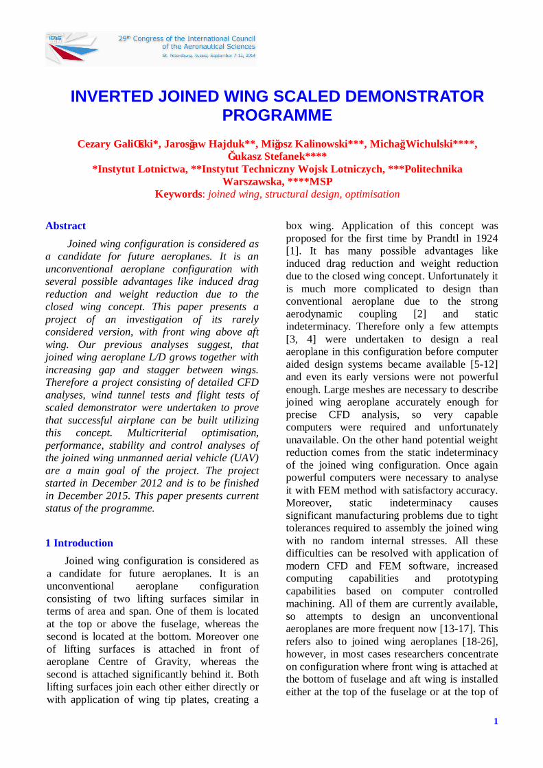
Joined wing configuration is considered as a candidate for future aeroplanes. It is an unconventional aeroplane configuration with several possible advantages like induced drag reduction and weight reduction due to the closed wing concept. This paper presents a project of an investigation of its rarely considered version, with front wing above aft wing. Our previous analyses suggest, that joined wing aeroplane L/D grows together with increasing gap and stagger between wings. Therefore a project consisting of detailed CFD analyses, wind tunnel tests and flight tests of scaled demonstrator were undertaken to prove that successful airplane can be built utilizing this concept. Multicriterial optimisation, performance, stability and control analyses of the joined wing unmanned aerial vehicle (UAV) are a main goal of the project. The project started in December 2012 and is to be finished in December 2015. This paper presents current status of the programme.
1 Introduction Joined wing configuration is considered as
a candidate for future aeroplanes. It is an unconventional aeroplane configuration consisting of two lifting surfaces similar in terms of area and span. One of them is located at the top or above the fuselage, whereas the second is located at the bottom. Moreover one of lifting surfaces is attached in front of aeroplane Centre of Gravity, whereas the second is attached significantly behind it. Both lifting surfaces join each other either directly or with application of wing tip plates, creating a
box wing. Application of this concept was proposed for the first time by Prandtl in 1924 [1]. It has many possible advantages like induced drag reduction and weight reduction due to the closed wing concept. Unfortunately it is much more complicated to design than conventional aeroplane due to the strong aerodynamic coupling [2] and static indeterminacy. Therefore only a few attempts [3, 4] were undertaken to design a real aeroplane in this configuration before computer aided design systems became available [5-12] and even its early versions were not powerful enough. Large meshes are necessary to describe joined wing aeroplane accurately enough for precise CFD analysis, so very capable computers were required and unfortunately unavailable. On the other hand potential weight reduction comes from the static indeterminacy of the joined wing configuration. Once again powerful computers were necessary to analyse it with FEM method with satisfactory accuracy. Moreover, static indeterminacy causes significant manufacturing problems due to tight tolerances required to assembly the joined wing with no random internal stresses. All these difficulties can be resolved with application of modern CFD and FEM software, increased computing capabilities and prototyping capabilities based on computer controlled machining. All of them are currently available, so attempts to design an unconventional aeroplanes are more frequent now [13-17]. This refers also to joined wing aeroplanes [18-26], however, in most cases researchers concentrate on configuration where front wing is attached at the bottom of fuselage and aft wing is installed either at the top of the fuselage or at the top of
INVERTED JOINED WING SCALED DEMONSTRATOR PROGRAMME
Cezary Galiński*, Jarosław Hajduk**, Miłosz Kalinowski***, Michał Wichulski****,
Łukasz Stefanek**** *Instytut Lotnictwa, **Instytut Techniczny Wojsk Lotniczych, ***Politechnika
Warszawska, ****MSP Keywords: joined wing, structural design, optimisation

Cezary Galiński, Jarosław Hajduk, Miłosz Kalinowski, Michał Wichulski, Łukasz Stefanek
2
the vertical stabilizer (Fig.1). Our previous experience lead to the conclusion that joined wing aeroplane could fly much better in upside down position [27]. The most probable reason of this fact comes from the interaction between wings. Front wing wake is very close to the aft wing if gap between wings is too small. It becomes even smaller at high angles of attack if front wing is located below aft wing. As a result aerodynamic advantages are diminished. They may be recovered if aft wing is installed high at the top of the vertical stabilizer, however this requires strong stabilizer which decreases potential weight reduction. Configuration, with front wing above aft wing should work in the opposite way, thus delivering expected advantages, providing that fuselage is reasonably high.
Fig.1 The joined wing aeroplane model built at the Warsaw University of Technology in early
nineties
Fig.2 Small UAV investigated in current project
Our recent CFD analyses confirm, that joined wing aeroplane L/D grows together with increasing gap and stagger between wings [28]. Moreover, assuming the same gap, configuration with front wing above aft wing provides not only greater maximum L/D, but also greater L/D in wider range of angles of attack. In particular L/D at high angles of attack is greater in this configuration which suggests advantageous flight endurance. Configuration with front wing below aft wing is advantageous only at low angles of attack assuming that aft wing is installed at the top of the vertical stabilizer. However, as mentioned before, weight advantage should be reduced in this case due to the increased loads of vertical stabilizer. As can be seen from this result, final conclusion is not clear yet and only a few designers share our belief [29], which was the motivation to undertake our current project. The concept of the project was described in [30, 31]. Multicriterial optimisation, performance, stability and control analyses of the joined wing unmanned aerial vehicle (UAV) are a main goal of the project. It is believed that it will allow for collecting an extensive database of knowledge concerning the inverted join-wing aeroplane configuration. Analysis and optimisation in this project are run for UAV since this allows for building inexpensive real flying test-bed. It will be tested with procedures of flight-testing developed in previous projects described in [32-35]. On the other hand UAVs were designed as a scaled down mock-ups of the future manned aeroplane.
Fig.3 Envisaged future manned aeroplane in
joined wing configuration

INVERTED JOINED WING SCALED DEMONSTRATOR PROGRAMME
3
Two UAVs are tested in this project, one with wing span of 1,2m (Fig.2) and second with wing span of 3m. First model was used to perform basic airworthiness experiments [30]. Second is equipped with much more advanced measurement and data acquisition system, so it will allow collecting detailed data on flight performance, stability and control. The same airframe was also used for wind tunnel testing.
2. Initial airworthiness Small UAV was built to prove that chosen
airplane configuration will allow performing the project safely. Its geometry was based on results of the calculations described in [28]. Dynamic directional/lateral stability was also verified with this model, except of basic airworthiness. Due to the application of quite short fuselage and pushing propulsion, it was not clear if single conventional vertical stabilizer and rudder would be effective. Therefore UAV was equipped with large, trapezoidal plates connecting front and aft wing. They were equipped with additional rudders. Left of them was deflectable only to the left and right of them was deflectable only to the right. During the first flight complete directional control system was used. Than side rudders were disengaged. Directional controllability was not significantly affected by this action. Therefore in the following flights both rudders and wing tip plates were gradually reduced. Finally it appeared that airplane is stable and controllable enough without side rudders and with minimal area of plates.
Small UAV allowed also investigating various combinations of elevator configuration. Elevator located at the whole trailing edge of the aft wing appeared the most effective while elevator using internal segments of control surfaces in front wing allowed achieving best performance. Deflection down of the front elevator was allowing not only decrease airspeed of the aeroplane, but also obtain greater L/D for achieved airspeed in a comparison with equivalent deflection up of the aft elevator. On the other hand aft elevator allowed achieving significantly smaller airspeeds. Finally it was decided that trailing edge of the aft wing will be used as elevator
while internal front control surfaces will be used as speed flap.
Ducted fan is considered as a possible propulsion system of the full scale aeroplane to decrease the danger of the propeller hitting the runway during the takeoff and landings. Therefore a ducted fan propulsion was also successfully tested on the small UAV
3. UAV design Large UAV adopted the same basic
geometry like small model, i.e. it has the same sweep angles, taper ratios and dihedral angles. Also chords and wing span were increased proportionally. Then advanced aerodynamic software presented in [36-38] was used to optimize airfoils, twist angles and radii of the wing-tip plates. This approach allowed to minimize the risk of the programme since basic airworthiness properties should not change too much between aeroplanes with the same basic geometry, while performance should be increased. The only changes could result from different moments of inertia and Reynolds number.
Fig.4 Large UAV geometry
CFD analysis with commercial software
[39] was also conducted performing sensitivity studies and investigating details of the large UAV aerodynamics [40]. Moreover it was necessary to estimate performance and aerodynamic loads of the UAV in flight and in the wind tunnel. Application of one airframe both for wind tunnel and flight testing complicates the design since more cases have to be analyzed. Usually loads achievable in the wind tunnel are greater than those achievable in flight. Moreover, fixing points for an aerodynamic balance have to be present in the structure. As a result the dual purpose structure
Cezary Galiński, Jarosław Hajduk, Miłosz Kalinowski, Michał Wichulski, Łukasz Stefanek
4
is slightly heavier than the structure designed only for flight testing. However weight difference is not as large as could be expected since ground handling loads have to be accounted for in both cases. Moreover, in many cases, lightness of the structure is constrained by specific weight of materials available (e.g. fabrics).
Fig.5 The lightest available carbon fabric applied for internal side of the sandwich panel
of the aft wing skin
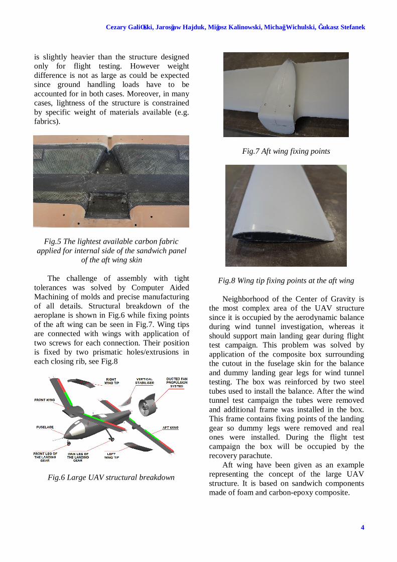
The challenge of assembly with tight tolerances was solved by Computer Aided Machining of molds and precise manufacturing of all details. Structural breakdown of the aeroplane is shown in Fig.6 while fixing points of the aft wing can be seen in Fig.7. Wing tips are connected with wings with application of two screws for each connection. Their position is fixed by two prismatic holes/extrusions in each closing rib, see Fig.8
Fig.6 Large UAV structural breakdown
Fig.7 Aft wing fixing points
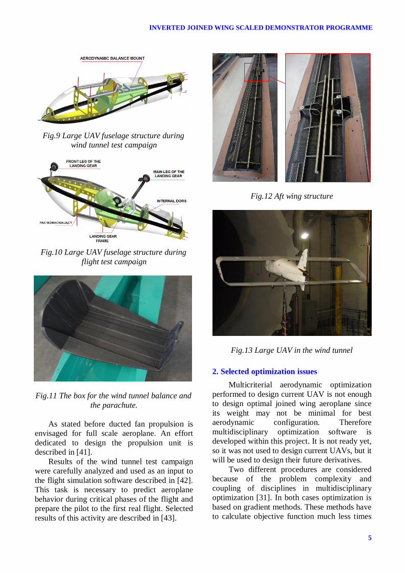
Fig.8 Wing tip fixing points at the aft wing Neighborhood of the Center of Gravity is
the most complex area of the UAV structure since it is occupied by the aerodynamic balance during wind tunnel investigation, whereas it should support main landing gear during flight test campaign. This problem was solved by application of the composite box surrounding the cutout in the fuselage skin for the balance and dummy landing gear legs for wind tunnel testing. The box was reinforced by two steel tubes used to install the balance. After the wind tunnel test campaign the tubes were removed and additional frame was installed in the box. This frame contains fixing points of the landing gear so dummy legs were removed and real ones were installed. During the flight test campaign the box will be occupied by the recovery parachute.
Aft wing have been given as an example representing the concept of the large UAV structure. It is based on sandwich components made of foam and carbon-epoxy composite.
INVERTED JOINED WING SCALED DEMONSTRATOR PROGRAMME
5
Fig.9 Large UAV fuselage structure during
wind tunnel test campaign
Fig.10 Large UAV fuselage structure during
flight test campaign
Fig.11 The box for the wind tunnel balance and
the parachute.
As stated before ducted fan propulsion is envisaged for full scale aeroplane. An effort dedicated to design the propulsion unit is described in [41].
Results of the wind tunnel test campaign were carefully analyzed and used as an input to the flight simulation software described in [42]. This task is necessary to predict aeroplane behavior during critical phases of the flight and prepare the pilot to the first real flight. Selected results of this activity are described in [43].
Fig.12 Aft wing structure
Fig.13 Large UAV in the wind tunnel
2. Selected optimization issues Multicriterial aerodynamic optimization
performed to design current UAV is not enough to design optimal joined wing aeroplane since its weight may not be minimal for best aerodynamic configuration. Therefore multidisciplinary optimization software is developed within this project. It is not ready yet, so it was not used to design current UAVs, but it will be used to design their future derivatives.
Two different procedures are considered because of the problem complexity and coupling of disciplines in multidisciplinary optimization [31]. In both cases optimization is based on gradient methods. These methods have to calculate objective function much less times

Cezary Galiński, Jarosław Hajduk, Miłosz Kalinowski, Michał Wichulski, Łukasz Stefanek
6
than probabilistic and genetic methods, which is advantageous because objective function calculation takes a lot of time in this case. First procedure is called “independent”. It assumes adding structural optimization into aerodynamic optimization loop. An independent full structural optimization is made for each step of geometry optimization. There are two independent objective functions here. Function of structural optimization is based on penalty function, which is maximizing stresses in structure to the predefined limit thus minimizing mass. Aerodynamic optimization is based on an objective function determining an airplane’s range.
This procedure does not guarantee finding global maximum of range with regard to outside geometry and structure simultaneously. It can only allow finding optimal structure for optimal geometry. That is why second procedure was created to compare solutions. It seems to be simpler but it needs much more calculations. In the second procedure there is one function consisting of objective function with penalty function. In each step both parameters of geometry and structure are optimized. Because of that much more aerodynamic analyzes are needed to find aerodynamic derivatives. Cost of calculation is compensated by possibility of finding global minimum with regard to all parameters of optimization.
Fig 14. Independent optimization
INVERTED JOINED WING SCALED DEMONSTRATOR PROGRAMME
7
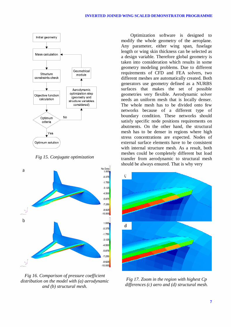
Fig 15. Conjugate optimization
Fig 16. Comparison of pressure coefficient distribution on the model with (a) aerodynamic
and (b) structural mesh.
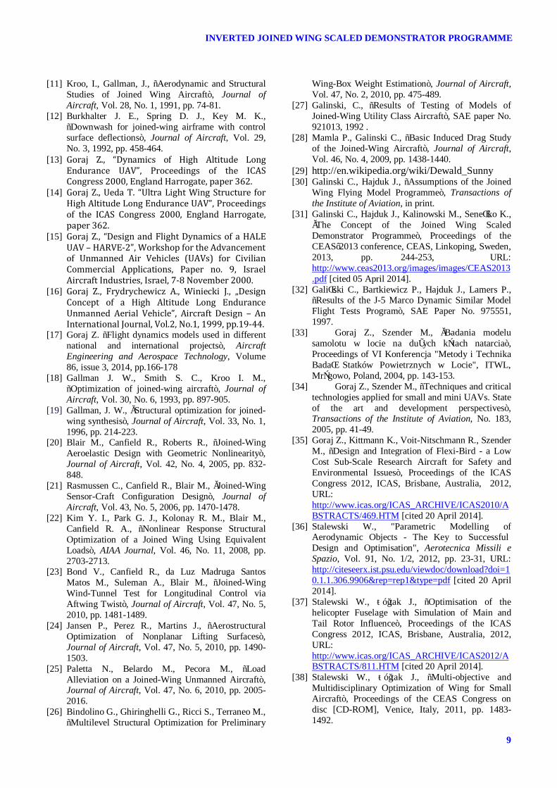
Optimization software is designed to modify the whole geometry of the aeroplane. Any parameter, either wing span, fuselage length or wing skin thickness can be selected as a design variable. Therefore global geometry is taken into consideration which results in some geometry modeling problems. Due to different requirements of CFD and FEA solvers, two different meshes are automatically created. Both generators use geometry defined as a NURBS surfaces that makes the set of possible geometries very flexible. Aerodynamic solver needs an uniform mesh that is locally denser. The whole mesh has to be divided onto few networks because of a different type of boundary condition. These networks should satisfy specific node positions requirements on abutments. On the other hand, the structural mesh has to be denser in regions where high stress concentrations are expected. Nodes of external surface elements have to be consistent with internal structure mesh. As a result, both meshes could be completely different but load transfer from aerodynamic to structural mesh should be always ensured. That is why very
Fig 17. Zoom in the region with highest Cp differences (c) aero and (d) structural mesh.

Cezary Galiński, Jarosław Hajduk, Miłosz Kalinowski, Michał Wichulski, Łukasz Stefanek
8
quick and reliable radial interpolation algorithm [44, 45] is used to transfer pressures onto structural mesh properly. It is resistant to creating local extremes. A cumulative error based on resultant forces is approximately 0.1% (error calculated for high angle of attack 16 degrees, when pressure gradients are very high). This is relatively small error and can be omitted. Errors of resultant force components in aircraft coordinate frame are presented in Tab.1.
Fig 18. Example of difference in Cp between (c)
aerodynamic and (d) structural mesh.
4 Summary Research programme was undertaken to explore characteristics of the join wing airplane with positive stagger (upper wing in front). The programme consists of optimization software development, numerical analyses, wind tunnel tests and UAVs flight tests. So far small model was built to investigate basic airworthiness. An airplane performed well, exhibiting correct stability and control characteristics. Larger model was designed with application of existing aerodynamic optimization software. The same airframe is to be used in wind tunnel and flight
test campaigns which generated a structural problem in the central part of the fuselage, where wind tunnel balance collided with landing gear. The problem was successfully solved by application of dummy landing gear that allowed building and testing UAV in the wind tunnel. Later on an airframe was modified and awaits for flight testing. Multidisciplinary optimization tool is developed to convert scaled demonstrator into practical UAV or manned experimental airplane.
5 Acknowledgements This work was supported by The National Centre for Research and Development under grant No. PBS/A6/14. Special thanks to the all personel of MSP company who manufactured the model.
References [1] Prandtl, L., “Induced drag of multiplanes”, NACA
TN 182, 1924. [2] Goraj Z., Kulicki P., Lasek M., „Aircraft Stability
Analysis For Strongly Coupled Aerodynamic Configuration”, Journal of Theoretical and Applied Mechanics, Vol. 35, No. 1, 1997, pp.137-158.
[3] Makarov, I. W., Lietalnyie apparaty MAI, Izdatielstwo MAI, Moscow, 1994, pp. 64-65.
[4] Sopher, R., “Design of a fairing for the junction of two wings”, Journal of Aircraft, Vol. 4, No. 4, 1967, pp. 379-382.
[5] Fairchild Samuels M., “Structural Weight Comparison of a Joined Wing and a Conventional Wing”, Journal of Aircraft, Vol. 19, No. 6, 1982, pp. 485-491.
[6] Wolkovitch, J., „The joined wing - An overview”, Journal of Aircraft, Vol. 23, No. 3, 1986, pp. 161-178.
[7] Miura H., Shyu A., Wolkovitch J., “Parametric weight evaluation of joined wings by structural optimization”, Journal of Aircraft, Vol. 25, No. 12, 1988, pp. 1142-1149.
[8] Hajela P., Chen J. L., “Preliminary weight estimation of conventional and joined wings using equivalent beam models”, Journal of Aircraft, Vol. 25, No. 6, 1988, pp. 574-576.
[9] Danilecki S., “Zamknięte skrzydło – zalety i wady (I)”, Technika Lotnicza i Astronautyczna, No. 9, 1988, pp. 4-6.
[10] Danilecki S., “Zamknięte skrzydło – zalety i wady (II)”, Technika Lotnicza i Astronautyczna, No. 10, 1988, pp. 8-10.
INVERTED JOINED WING SCALED DEMONSTRATOR PROGRAMME
9
[11] Kroo, I., Gallman, J., “Aerodynamic and Structural Studies of Joined Wing Aircraft”, Journal of Aircraft, Vol. 28, No. 1, 1991, pp. 74-81.
[12] Burkhalter J. E., Spring D. J., Key M. K., “Downwash for joined-wing airframe with control surface deflections”, Journal of Aircraft, Vol. 29, No. 3, 1992, pp. 458-464.
[13] Goraj Z., “Dynamics of High Altitude Long Endurance UAV”, Proceedings of the ICAS Congress 2000, England Harrogate, paper 362. [14] Goraj Z., Ueda T. “Ultra Light Wing Structure for High Altitude Long Endurance UAV”, Proceedings of the ICAS Congress 2000, England Harrogate, paper 362. [15] Goraj Z., “Design and Flight Dynamics of a HALE UAV – HARVE-2”, Workshop for the Advancement of Unmanned Air Vehicles (UAVs) for Civilian Commercial Applications, Paper no. 9, Israel Aircraft Industries, Israel, 7-8 November 2000. [16] Goraj Z., Frydrychewicz A., Winiecki J., „Design Concept of a High Altitude Long Endurance Unmanned Aerial Vehicle”, Aircraft Design – An International Journal, Vol.2, No.1, 1999, pp.19-44. [17] Goraj Z. “Flight dynamics models used in different
national and international projects”, Aircraft Engineering and Aerospace Technology, Volume 86, issue 3, 2014, pp.166-178
[18] Gallman J. W., Smith S. C., Kroo I. M., “Optimization of joined-wing aircraft”, Journal of Aircraft, Vol. 30, No. 6, 1993, pp. 897-905.
[19] Gallman, J. W., „Structural optimization for joined-wing synthesis”, Journal of Aircraft, Vol. 33, No. 1, 1996, pp. 214-223.
[20] Blair M., Canfield R., Roberts R., “Joined-Wing Aeroelastic Design with Geometric Nonlinearity”, Journal of Aircraft, Vol. 42, No. 4, 2005, pp. 832-848.
[21] Rasmussen C., Canfield R., Blair M., „Joined-Wing Sensor-Craft Configuration Design”, Journal of Aircraft, Vol. 43, No. 5, 2006, pp. 1470-1478.
[22] Kim Y. I., Park G. J., Kolonay R. M., Blair M., Canfield R. A., “Nonlinear Response Structural Optimization of a Joined Wing Using Equivalent Loads”, AIAA Journal, Vol. 46, No. 11, 2008, pp. 2703-2713.
[23] Bond V., Canfield R., da Luz Madruga Santos Matos M., Suleman A., Blair M., “Joined-Wing Wind-Tunnel Test for Longitudinal Control via Aftwing Twist”, Journal of Aircraft, Vol. 47, No. 5, 2010, pp. 1481-1489.
[24] Jansen P., Perez R., Martins J., “Aerostructural Optimization of Nonplanar Lifting Surfaces”, Journal of Aircraft, Vol. 47, No. 5, 2010, pp. 1490-1503.
[25] Paletta N., Belardo M., Pecora M., “Load Alleviation on a Joined-Wing Unmanned Aircraft”, Journal of Aircraft, Vol. 47, No. 6, 2010, pp. 2005-2016.
[26] Bindolino G., Ghiringhelli G., Ricci S., Terraneo M., “Multilevel Structural Optimization for Preliminary
Wing-Box Weight Estimation”, Journal of Aircraft, Vol. 47, No. 2, 2010, pp. 475-489.
[27] Galinski, C., “Results of Testing of Models of Joined-Wing Utility Class Aircraft”, SAE paper No. 921013, 1992 .
[28] Mamla P., Galinski C., “Basic Induced Drag Study of the Joined-Wing Aircraft”, Journal of Aircraft, Vol. 46, No. 4, 2009, pp. 1438-1440.
[29] http://en.wikipedia.org/wiki/Dewald_Sunny [30] Galinski C., Hajduk J., “Assumptions of the Joined
Wing Flying Model Programme”, Transactions of the Institute of Aviation, in print.
[31] Galinski C., Hajduk J., Kalinowski M., Seneńko K., „The Concept of the Joined Wing Scaled Demonstrator Programme”, Proceedings of the CEAS’2013 conference, CEAS, Linkoping, Sweden, 2013, pp. 244-253, URL: http://www.ceas2013.org/images/images/CEAS2013.pdf [cited 05 April 2014].
[32] Galiński C., Bartkiewicz P., Hajduk J., Lamers P., “Results of the J-5 Marco Dynamic Similar Model Flight Tests Program”, SAE Paper No. 975551, 1997.
[33] Goraj Z., Szender M., „Badania modelu samolotu w locie na dużych kątach natarcia”, Proceedings of VI Konferencja "Metody i Technika Badań Statków Powietrznych w Locie", ITWL, Mrągowo, Poland, 2004, pp. 143-153.
[34] Goraj Z., Szender M., “Techniques and critical technologies applied for small and mini UAVs. State of the art and development perspectives”, Transactions of the Institute of Aviation, No. 183, 2005, pp. 41-49.
[35] Goraj Z., Kittmann K., Voit-Nitschmann R., Szender M., “Design and Integration of Flexi-Bird - a Low Cost Sub-Scale Research Aircraft for Safety and Environmental Issues”, Proceedings of the ICAS Congress 2012, ICAS, Brisbane, Australia, 2012, URL: http://www.icas.org/ICAS_ARCHIVE/ICAS2010/ABSTRACTS/469.HTM [cited 20 April 2014].
[36] Stalewski W., "Parametric Modelling of Aerodynamic Objects - The Key to Successful Design and Optimisation", Aerotecnica Missili e Spazio, Vol. 91, No. 1/2, 2012, pp. 23-31, URL: http://citeseerx.ist.psu.edu/viewdoc/download?doi=10.1.1.306.9906&rep=rep1&type=pdf [cited 20 April 2014].
[37] Stalewski W., Żółtak J., “Optimisation of the helicopter Fuselage with Simulation of Main and Tail Rotor Influence”, Proceedings of the ICAS Congress 2012, ICAS, Brisbane, Australia, 2012, URL: http://www.icas.org/ICAS_ARCHIVE/ICAS2012/ABSTRACTS/811.HTM [cited 20 April 2014].
[38] Stalewski W., Żółtak J., “Multi-objective and Multidisciplinary Optimization of Wing for Small Aircraft”, Proceedings of the CEAS Congress on disc [CD-ROM], Venice, Italy, 2011, pp. 1483-1492.

Cezary Galiński, Jarosław Hajduk, Miłosz Kalinowski, Michał Wichulski, Łukasz Stefanek
10
[39] Ansys Fluent CFD software package, URL: http://www.ansys.com/Products/Simulation+Technology/Fluid+Dynamics/Fluid+Dynamics+Products/ANSYS+Fluent [cited 28 June 2014].
[40] Dziubiński A., Kuprianowicz S., Surmacz K., Galiński C., Żółtak J., „The Joined Wing Scaled Demonstrator Results of CFD Analysis”, Proceedings of the ICAS’2014 conference, ICAS, Petersburg, Russia, 2014, ICAS2014-1.10ST, in print.
[41] Bogdański K.; Rodzewicz M., Krusz W.; Rutkowski M.; „Design and Optimization of Low Speed Ducted Fan for a New Generation of Joined Wing Aircraft”, Proceedings of the ICAS’2014 conference, ICAS, Petersburg, Russia, 2014, ICAS2014-P2.4.13, in print
[42] Goetzendorf-Grabowski T.; Mieszalski D.; Marcinkiewicz E.; “Stability analysis using SDSA tool”, Progress in Aerospace Sciences, Volume: 47 Issue: 8 Special Issue: SI Pages: 636-646 Published: NOV 2011
[43] Lis M., Dziubiński A., Galiński C., Krysztofiak G., Ruchała P., Surmacz K., “Predicted Flight Characteristics of the Inverted Joined Wing Scaled Demonstrator”, Proceedings of the ICAS’2014 conference, ICAS, Petersburg, Russia, 2014, ICAS2014-P2.4.13, in print
[44] Frankie R., “Scattered data interpolation: tests of some methods”, Math. Comp., 38(157), 1982, pp. 181–200.
[45] Schaback R. and Wendland H., “Characterization and construction of radial basis functions”, in “Multivariate Approximation and Applications”, Cambridge University Press, 2001, N. Dyn, D. Leviatan, D. Levin and A. Pinkus Editors.
Copyright Statement The authors confirm that they, and/or their company or organization, hold copyright on all of the original material included in this paper. The authors also confirm that they have obtained permission, from the copyright holder of any third party material included in this paper, to publish it as part of their paper. The authors confirm that they give permission, or have obtained permission from the copyright holder of this paper, for the publication and distribution of this paper as part of the ICAS 2014 proceedings or as individual off-prints from the proceedings.