Embed Size (px)
Citation preview

T e c h n i c a l N o t e
Artificial Lift Drives
December, 2003


Artificial Lift Drives
TECHNICALNOTE
OverviewUnico artificial lift drives are engineered and manufacturedspecifically foroil-fieldpumping applications. They provideprecision control in a rugged, dependable package.Digital technology delivers precise control of motorvoltage, current, speed, and torque to make the driveresponsive to continuously changing downhole conditions.Advanced control features increaseproductivity, improveenergy efficiency, and extend the life of both new andexisting artificial lift systems.
Unico drives are the only ones that can be configuredin the field to operate all varieties of pumps includingretrofits of existing installations. Firmware packagesare available that allow the same basic package tooperate electric submersible, progressing cavity, orsucker-rod pumps.
Superior EvolutionUnico drives have evolved from more than 30 yearsexperience with some of the most demanding driveapplications in the world. Unico is the industry leaderin experience with all forms of artificial lift includingelectric submersible, progressing cavity, and suckerrod pumping. That experience ranges from small coalbed methane dewatering pumps to large heavy-oilsubmersibles. Thousands of Unico drives are operatingartificial lifts from the tropics to the arctic.
Superior FlexibilityUnico drives are designed for operation from 230-240 V,380-415 V, 460-480 V, or 575-600 V 50/60 Hz powersources. Units are also available for operation fromsingle-phase power lines. Asimple parameter selectionallows the drive to operate in a variable-frequency orflux-vector mode to match the needs of the pumpingapplication. The drive also can be reconfigured in thefield to operate electric submersible, progressingcavity, or sucker rod pumps. This flexibility is useful inmeeting production requirements that evolve over thelife of a well.
The drive can be programmed by the user in ladderdiagrams and function blocks to meet specific orfuture application needs. Analog and digital I/O canalso be programmed for advanced well automation.Constant-power control can be used to increase wellproduction by operating motors above base speedduring periods of reduced torque demand.
Superior ReliabilityUnico drives are assembled and tested to rigorousqualitystandards. Computerized in-circuit and functionaltests are used to eliminate even the most subtle defects.Drives and all their assembled components carry serialnumbers for full traceability throughout the product life.Assembled drives are cycle- and life-tested to insuretrouble-free operation at rated and overload conditions.First-pass test yields and repair root-cause analysisare used to maintain quality levels and improveproduct reliability.
Ease of UseA keypad/display provides access to system parametersthat are organized into logical groupings for easynavigation. Multi-level password protection preventsunintended alteration of system setup parameters. Themain display screen provides immediate readouts offour parameters such as current, voltage, frequency,torque,speed, position, pressure, flow, temperature,and status. An event/warning/fault log is used to capturetime-stamped diagnostic information to aid in trouble-shooting drive or pump problems.

2 Artificial Lift DrivesTECHNICAL NOTE
Process ControlUnico drives include three analog inputs as well as aneight-channel data-acquisition option for monitoringmultiple operating parameters such as position, force,flow, pressure, and temperature. Multiple analog outputsare available for controlling the pumping system ordisplaying the operational information. Analog channelshave high/low limit alarms that monitor the integrity ofprocess control signals. Each analog signal can becalibrated into meaningful engineering units such asdegrees, pounds, percent, Hz, rpm, bpd, gpm, feet,meters, psi, bars, kPa, or degrees F or C. PID regulatorscan be used for closed-loop process control of wellpressure, pump flow, or fluid level.
Utility-Friendly DesignUnico drives incorporate unique design features thatreduce electric utility costs and improve power quality.Advanced pump-control strategies minimize the energycost-per-barrel of fluid produced. The drives are capableof providing near-unity power factor at all speeds andloads to avoid utility power factor penalties.
Drives incorporate link chokes to reduce harmoniccurrents that could distort line voltages. Harmonic-eliminator and 12-pulse connection options are availableto eliminate practically all harmonic currents to satisfyIEEE 519 guidelines. A power-monitor feature quantifiespower consumption and system efficiency. Time-of-usecontrol allows the system to pause operation duringperiods of peak utility charges.
Flexible PackagingArtificial lift drives are packaged for either outdoor orindoor installations. Outdoor packages are heavy-gaugeenclosures rated for NEMA 3 (IP 64) environments.Mounting channels permit convenient movement andprovide stable mounting at the well site. Heat sinksand heat exchangers that dissipate heat externally byextending through the enclosure walls are protected byrain shields. Indoor packages can be provided as wall-or floor-mounted units and use forced ventilation ratherthan heat exchangers for cooling.
Networking CapabilityUnico drives incorporate a number of communicationprotocols. Protocols are available for communicationwith popular programmable controllers as well aspersonal computers or network servers. An enhancedModbus RTU protocol allows efficient transfer of both16- and 32-bit data as well as logic on/off signals. Thisprotocol can be used to access data locally through apersonal computer or remotely through radio links andSCADA systems. A wireless interface module is availablefor remote monitoring and control of the artificial liftsystem. Optional modules are available for Modbus Plus,ControlNet, Profibus, and Ethernet communications.Software is available to monitor drives using Palm OShandheld devices and Windows-based personalcomputers or network servers. Reporting software isavailable for sucker-rod pump drives that providesdynamometer graphs and other important analyticaland diagnostic information either in the field or remotely.

Artificial Lift Drives 3TECHNICAL NOTE
Sucker Rod PumpingThe drive can be configured to provide featuresspecifically designed for operation of all sizes of Class I,Class III, phased-crank, air-balanced, beam-balanced,Mark II, Reverse Mark, and Rotaflex sucker-rodpumps (SRPs).
Multiple constraint optimization is used to maximizeproduction, improve efficiency, and increase reliabilityfor all pumping situations. Limits set by motor speed,motor temperature, gearbox torque, rod load, rodvelocity, and pump fill are enforced at appropriate pointsin the pump cycle. Monitors display input, motor, rod,and lift power as well as cumulative power consumptionand system energy efficiency. Power demand limitersand power flow optimizers are particularly beneficial inwells with highly variable inflow rates, such as thosefound in coal-bed methane production, high gas/oilratio wells, and cyclic steam operations.
A gearbox ratio monitor automatically computes theoverall ratio between the motor and crank shaft with eachstroke of the pump. A belt slippage monitor provides analarm for any belt slippage outside of a predeterminedlimit. A gearbox torque limiter protects the gearbox fromexcessive torque loads. A crank position monitor providesa continuous reading of the angle of the crank shaft.
A pump speed monitor provides the instantaneousand average pump speeds. An electronic limit switchprovides adjustable crank angle points for changingpump upstroke, downstroke, and cornering speeds.A pump speed selector provides for independentupstroke, downstroke, and cornering speeds fromexternal potentiometers, keypad preset inputs, or serialcommunication channels.
A bridle separation limiter prevents rod float by auto-matically adjusting downstroke speed for minimumrod load. A counterbalance monitor displays pumpimbalance to assist in the selection of the number andposition of counterweights to minimize gearbox stressand energy consumption.
A pump fill monitor continuously measures and displaysthe pump fill percentage. A pump-off controller allowsthe pump to dwell for a programmable period for wellswith low inflow. A dwell period minimum pump speedcan be used to prevent sanding-in of the pump. Apump fill optimizer maximizes well production andeliminates fluid pound by independently adjustingupstroke and downstroke speeds.
A rod string calculator uses rod dimensions and fluidproperties to compute rod buoyant weight and resonantfrequency. A pump flow monitor provides a continuousestimate of pump flow without the need for additionalinstrumentation. A resettable production monitoraccumulates total production, and an efficiency monitordisplays the overall effectiveness of the pumping system.
Rod and pump monitors provide continuous measuresof polished rod and downhole pump velocities andpositions. The rod and pump monitors also providecontinuous measures and displays of polished rod anddownhole pump forces.
Rod force is available directly from a load cell or internallygenerated in the drive without the need for externalinstrumentation. A rod force limiter allows independentcontrol of maximum rod force on the upstroke andminimum rod force on the downstroke.
A data sampler captures data for generation of crankspeed and gearbox torque plots as well as surfaceand downhole dynamometer cards. A data loggerautomatically collects time-stamped faults, warnings,and events for subsequent retrieval through thekeypad/display or communication port.

4 Artificial Lift DrivesTECHNICAL NOTE
Electric Submersible PumpingThe drive can be configured to provide a number offeatures specifically designed for electric submersiblepumps (ESPs).
The drive provides manual, remote, and automaticcontrol of pump speed or fluid level. A fluid level controlincorporates tubing, casing, and intake pressure toprecisely regulate the fluid level above the pump. Fluidlevel control maximizes gas production by regulatingthe downhole pump inlet pressure. A search routineuses a gas flow sensor to automatically find the fluidlevel that maximizes gas production. Pump parametersare used to eliminate the need for a downhole pressuresensor for fluid level.
A pump off control suspends or pauses pump operationto protect the pump or to control average flow. Monitorsdisplay downhole pump speed and torque as well aspump input and output power. Pump pressure, fluid level,fluid flow, gas flow, fluid production, and gas productionare displayed in selectable engineering units.
A power optimizer reduces the electric utility cost forany inflow rate. Auto restart control sequences pumpstarting after power outages to eliminate surges inpower demand. Time-of-use control can be used tominimize on-peak energy demand charges. Monitorsdisplay motor voltage, motor current, motor power, andlift power. The drive also incorporates an input powermeter and an average efficiency display to aid in utilitycost control.
A torque limiter protects the motor and pump fromexcessive torque loads. Overload and underloaddetection protect submersible motors and pumps fromdamage. Current limit control increases productionfrom gassy wells by increasing motor speed duringperiods of reduced pump load. Auxiliary logic can beprogrammed in the drive for automatic operation of gasand water valves.
A multichannel analog I/O option allows data loggingand remote monitoring of additional well parameters. Aserial communication channel allows remote monitoringand control of pump operation. A data logger automaticallycollect time-stamped operational changes and faultconditions for subsequent retrieval through the keypad/display or communication port. A data sampler capturesreal-time data for generation of motor, pump, andproduction information.
Pump Specification Curves
0.0
200.0
400.0
600.0
800.0
1000.0
1200.0
1400.0
1600.0
0.0
8.5
17.0
25.6
34.1
42.6
51.1
59.6
68.1
76.7
85.2
Pump Flow (Gpm)
0.0
10.0
20.0
30.0
40.0
50.0
60.0
70.0
80.0Pump Pressure
Pump Efficiency
Input Power
Pu
mp
Hea
d (
Fee
t)
Pump Flow (Gpm)

Artificial Lift Drives 5TECHNICAL NOTE
Progressing Cavity PumpingThe drive can be configured to provide featuresspecifically designed for operation of progressingcavity pumps (PCPs).
The drive provides manual, remote, and automaticcontrol of pump speed or fluid level. A fluid level controlincorporates tubing, casing, and intake pressure toprecisely regulate the fluid level above the pump. Fluidlevel control maximizes gas production by regulatingthe downhole pump inlet pressure. A search routineuses a gas flow sensor to automatically find the fluidlevel that maximizes gas production. Pump parametersare used to eliminate the need for a downhole pressuresensor for fluid level or a surface flow meter for fluid flow.
A pump off control suspends or pauses pump operationto protect the pump or to control average flow. Monitorsdisplay polished rod speed and torque as well as down-hole pump speed and torque. Pump pressure, fluid level,fluid flow, gas flow, fluid production, and gas productionare displayed in selectable engineering units.
A power optimizer reduces the electric utility cost forany inflow rate. Auto restart control sequences pumpstarting after power outages to eliminate surges inpower demand. Time-of-use control can be used tominimize on-peak energy demand charges. Monitorsdisplay motor voltage, motor current, motor power, andlift power. The drive also incorporates an input powermeter and an average efficiency display to aid in utilitycost control.
Dual motor capability allows large PCPs to be operatedby a single drive. Torque limiting and stick-slip oscillationdamping protect the rod string against breakage.Current foldback maximizes well production whileprotecting the motor against overheating. Underspeeddetection protects the system in case of a stall condition,such as a stuck pump.
Breakaway torque detection identifies pump problemsduring starting. Low torque detection indicates a rodbreak, belt failure, or plugged sand screen. Sensing ofpump inlet and outlet differential pressure preventspump overloading. Pump-off control maximizes wellproduction for any given inflow characteristic.
A multichannel analog I/O option allows data loggingand remote monitoring of additional well parameters. Aserial communication channel allows remote monitoringand control of pump operation. A data logger automaticallycollect time-stamped operational changes and faultconditions for subsequent retrieval through the keypad/display or communication port. A data sampler capturesreal-time data for generation of motor, pump, andproduction information.

6 Artificial Lift DrivesTECHNICAL NOTE
Heavy-duty 14 gauge enclosuredesigned for NEMA 3 outdoor environments
Mounting channelsfor convenient handlingand stable mounting
Flange mounted circuit breaker operatorinterlocked with enclosure door for safety
Ground and motorconnection terminalsare located at a convenient lower access point
Rectifier control module• controls an SCR bridge to provide precise
regulation of bus voltage for changing line and load conditions
• detects input power problems including low line voltage, high line voltage, and phase loss
Inverter control module• controls an IGBT bridge to provide six-step ,
trapezoidal, or sinusoidal voltages• provides open-loop variable-frequency or
closed-loop flux-vector control• provides serial, analog, and digital I/O
connections• controls the operator interface keypad
and display
Swing-out doorprovides access to the rectifier andinverter power semiconductors
Air-to-air heat exchangeprovides cooling of theinterior of the enclosure
Door mounted keypad/displayand operator devicescan be protected by an optionallockable weatherproof access cover
Signal connectionsare grouped conveniently on acustomer connection panel

Artificial Lift Drives 7
TECHNICAL NOTE
Operator DisplayThe Operator Display can be easily programmed todisplay any four variables within the control. Typicaldisplay parameters include pump speed, pump fill, pumphead, pump flow, fluid level, motor current, motor voltage,motor frequency, speed source, and drive status.
Bar Graph DisplayThe Bar Graph Display shows drive parameters in bothbar graph and numeric format. The keypad can beused to scroll through a pre-defined set of display variables such as speeds, currents and voltages.
Data Logger DisplayThe Data Logger Display is used to display the source andtime of event, warning, and fault conditions. The keypadcan be used to scroll through the event/warning/faulthistory and to clear logged conditions.
Dictionary MenuThe Dictionary Menu provides access to the parametersthat define the operating characteristics of the drive aswell as the useful display variables. Parameters arearranged in such groupings as Operator, Well, Pump,Control, Power, Timer, Drive, Input, Output,Communications, and so forth.
Parameter DisplayThe Parameter Display is used to observe or enter data.The keypad can be used to scroll through a group ofparameters or jump to a specific parameter. The keypadis also used to adjust parameters provided a passwordhas been entered to give access.
Operator Device ClusterUnico artificial lift drives provide for up to 12 operatordevices such as push buttons, selectors, indicators, andpotentiometers. A typical configuration includes a keypad/display for setting and observing system parameters,speed setting potentiometers, motor on and faultindicators that show drive status, a two-position selectorfor run or stand-by mode, and a three-position selectorfor manual, auto, or remote speed selection.
Operator Data InterfaceThe Operator Data Interface has been designed forease of use for startup, monitoring,and troubleshooting.A 2-line by 24-character display provides easily readtext and graphics. A 16-button keypad allows simplemenu navigation and data entry. Password protection isused to prevent unauthorized access todriveparameters.On-line setup instructions, prompts, warnings, bar graphdisplays, and logical data groupings result in fast startups,smooth operation, and minimum downtime.
8 Artificial Lift DrivesTECHNICAL NOTE
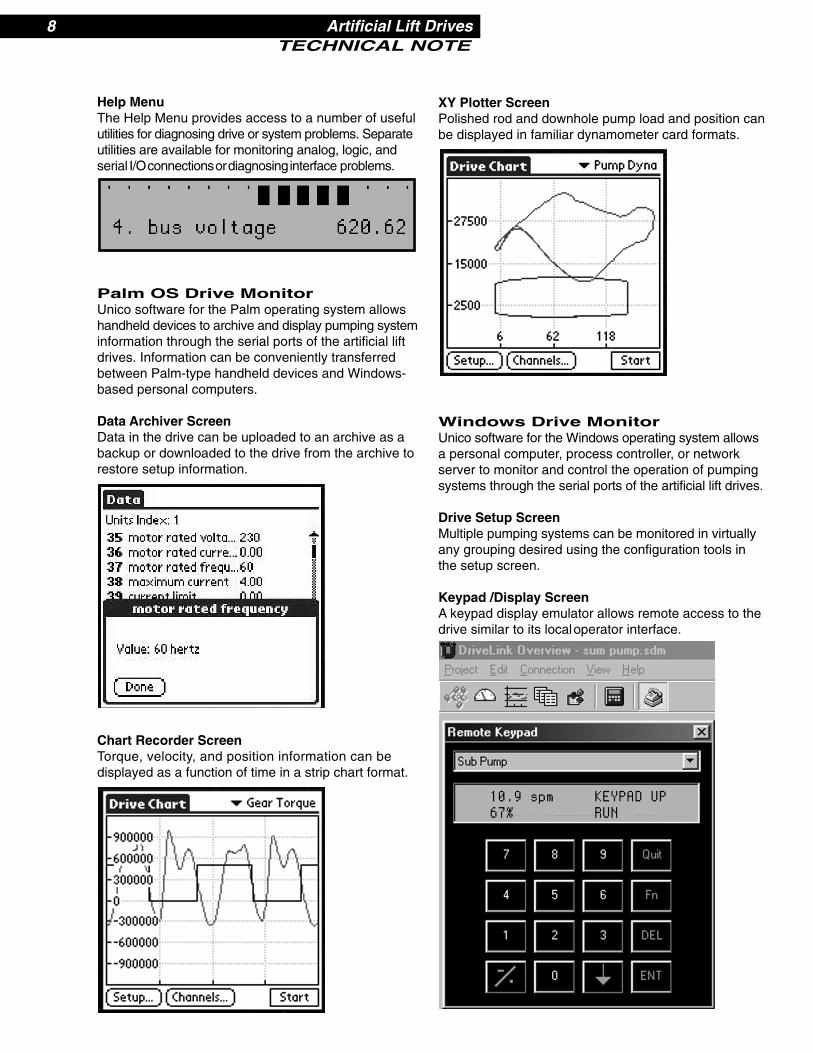
Help MenuThe Help Menu provides access to a number of usefulutilities for diagnosing drive or system problems. Separateutilities are available for monitoring analog, logic, andserial I/Oconnectionsordiagnosinginterface problems.
Palm OS Drive MonitorUnico software for the Palm operating system allowshandheld devices to archive and display pumping systeminformation through the serial ports of the artificial liftdrives. Information can be conveniently transferredbetween Palm-type handheld devices and Windows-based personal computers.
Data Archiver ScreenData in the drive can be uploaded to an archive as abackup or downloaded to the drive from the archive torestore setup information.
Chart Recorder ScreenTorque, velocity, and position information can bedisplayed as a function of time in a strip chart format.
XY Plotter ScreenPolished rod and downhole pump load and position canbe displayed in familiar dynamometer card formats.
Windows Drive MonitorUnico software for the Windows operating system allowsa personal computer, process controller, or networkserver to monitor and control the operation of pumpingsystems through the serial ports of the artificial lift drives.
Drive Setup ScreenMultiple pumping systems can be monitored in virtuallyany grouping desired using the configuration tools inthe setup screen.
Keypad /Display ScreenA keypad display emulator allows remote access to thedrive similar to its localoperator interface.

Artificial Lift Drives 9TECHNICAL NOTE
Data Archiver ScreenPumping system data in the drive can be uploaded toan archive as a backup or download to the drive fromthe archive to restore prior setup information. A compareutility is available that highlights differences betweencurrent and archive set up parameters.
Chart Recorder ScreenTorque, velocity, and position information can bedisplayed as a function of time in a strip chart format.
XY Plotter ScreenPolished rod and downhole pump load and positioncan be displayed in familiar dynamometer card formats.
Circle Chart ScreenPump system parameters can be conveniently displayedover an extended period, such as a day, in a circle-chart format.
Analog Meter ScreenPumping system analog variables in the drive can bedisplayed in a variety of meter formats that includeminimum/maximum detection.
Programmable Logic ControllerUnico artificial lift drives incorporate a ProgrammableLogic Controller (PLC) that can be used to monitordrive operation, customize the drive to unique systemneeds, or provide a simple migration path for futureupgrades. The PLC language is based on the IEC1131 open standard and includes both ladder diagramsand function blocks. Ladder diagrams, function blocks,digital I/O, and analog I/O can be monitored in realtime. Analog data can be displayed in chart recorderand XY plotter formats.

10 Artificial Lift DrivesTECHNICAL NOTE
Drive Setup ScreenMultiple pumping systems can be monitored in virtuallyany grouping desired using the configuration tools inthe setup screen.
Ladder Diagram ScreenLogic type signals can be programmed and monitoredin familiar ladder diagram formats.
Function Block ScreenAnalog type signals can be manipulated and monitoredusing a rich variety of function blocks.
Input/Output ScreenInput and output signals can be forced and monitoredusing a convenient I/O display panel.
Data Archiver ScreenPumping system data in the drive can be uploaded toan archive as a backup or download to the drive fromthe archive to restore prior setup information. A compareutility is available that highlights differences betweencurrent and archive set up parameters.
Chart Recorder ScreenForce, torque, velocity, and position information can bedisplayed as a function of time in a strip chart format.
XY Plotter ScreenRod and pump load and position can be displayed infamiliar dynamometer card formats.

Artificial Lift Drives 11TECHNICAL NOTE
Report GeneratorUnico report generator software conveniently summarizesimportant analytical and diagnostic information aboutESP, PCP, and SRP field applications. Well parameterscan displayed in numeric or graphical formats as wellas in multiple languages. The report is written in Excel,which allows users to customize the report template fortheir specific needs.

12 Artificial Lift DrivesTECHNICAL NOTE
General Features• All-digital control for responsive and repeatable
motor operation• 24-bit Digital Signal Processor (DSP) for fast,
dynamic response• 32 kilobytes battery backup memory for application
setup data• 142 kilobytes scratch pad memory and 1.5
megabytes firmware memory• Clock/calendar maintains accurate time during
power outages• High switching frequency IGBT devices for
smooth, quiet operation• Flux vector operation for precise control of motor
current, torque, and velocity• Constant horsepower operation above base speed• Dynamic braking control option for absorbing
regenerated energy• Auto restart for quick restoration of operation• User-programmable analog and digital inputs
and outputs• Integral DC link choke for high power factor and
low total harmonic distortion• External heat sink for efficient heat dissipation
outside the enclosure• Air-to-air heat exchanger for cooling electronic
equipment• User programmable ladder diagrams and
function blocks
Ease of Installation andMaintenance
• Automated setup features require no chart recorders or meters
• Digital parameter adjustment for precise and repeatable settings
• Software calibration and adjustment eliminates tuning components
• Complete, self-contained package requires minimal option boards
• Identical control boards across full power range reduces spare parts
• Snap-in signal connections for ease of wiring and parts replacement
• Automated hardware configuration check
Ease of Use• Touch keypad for easy entry of application-specific
setup adjustments• Two line by 24-character descriptive, plain-language
display• Process variable display in bar graph and
engineering units• Comprehensive self-diagnostic message display• Real-time data sampling of dynamic information • Serial ports for communication with process
controllers and personal computers • Time-stamped event/warning/fault logs for capturing
diagnostic information
Reliable Operation• Tolerant of AC line voltage and frequency
fluctuations• Momentary power loss ride-through for reducing
nuisance trips• Programmable auto restart for unattended
operation• Extensive electronic protection circuits reduce
failures• Optical isolation option to provide high noise
immunity• Rugged, completely sealed package for outdoor
installation• Multilevel security code prevents unauthorized
parameter changes• Lockout of local operator controls for safe remote
operation

Artificial Lift Drives 13TECHNICAL NOTE
Specifications
Electrical
Input SupplyVoltage: 230, 380, 460, or 575 V AC (±10%)Frequency: 47 to 63 Hz
Power FactorOverall: 1.00 displacement power factor
0.94 overall power factor at all speeds
Output RatingVoltage: Zero to input voltage, three-phaseFrequency: Zero to 120 Hz flux vector control
Zero to 300 Hz variable frequency controlSwitching frequency: Programmable, 2 to 12 kHzOverload current: Constant torque (CT): 150% to 200% of rated for 1 minute
maximum of 200% ratedVariable torque (VT): 120% to 150% of rated for 1 minute
maximum of 140% to 160% of ratedExtended torque (ET): 110% to 120% of rated for 1 minute
maximum of 120% to 140% of ratedConversionRectifier unit: Six-Diode, three-phase (6-pulse) full wave bridge below 150 hp CT
Diode-SCR, six-phase (12-pulse) full-wave bridge for 40 hp CT and aboveInverter unit: Six-IGBT, four-quadrant, trap wave or sine wave output
Environmental
Operating temperature: 32° to 122° F (0° to 50° C)Storage temperature: 5° to 158° F (–15° to 70° C)Relative humidity: 5% to 95%, noncondensingAltitude: 0 to 3,300 ft. (1,000 m) at full rating
Inputs and Outputs
Analog InputsThree 12-bit analog inputs (±10 V DC or 4 to 20 mA)
Analog OutputsTwo 12-bit analog outputs (±10 V DC and 4 to 20 mA)
Digital Inputs12 digital inputs (requires sink of 1mA to common)
Digital OutputsSix digital outputs (open-collector drivers rated 24 V DC @ 500 mA)
Serial Communications
Asynchronous ports: EIA RS-232 and RS-422/485, isolated, 0.3 to 19.2 and 0.3 to 115.2 kbaudStandard: ANSI-x3.28-2.5-A4 and Modbus RTU protocolsOptional: Modbus Plus, ControlNet, Profibus, and Ethernet
MaxStream wireless communications
Protection
• Motor overload • Heat sink overtemperature• Motor short circuit • Power transistor fault• Input overvoltage • Logic power undervoltage• Input undervoltage • Memory malfunction• Instantaneous overcurrent • Processor execution fault• Ground fault

All trade designationsare provided withoutreference to the rights oftheir respective owners.
Specifications subject tochange without notice.
9135 12/03
CorporateHeadquarters
Unico, Inc.3725 Nicholson RoadP. O. Box 0505Franksville, Wisconsin53126-0505USA
voice: 262.886.5678fax: 262.504.7396
www.unicous.com
United StatesNovi, Michigan248.380.7610
New Lenox, Illinois815.485.5775
Sandy, Utah801.501.7586
CanadaMississauga,Ontario905.602.4677
South AmericaEl Tigre, Venezuela58.283.241.4024
EuropeMilton Keynes,England44.1.908.260000
Siegen, Germany49.271.5015.0
AsiaOsaka, Japan81.66.945.0077
Beijing, China86.10.6218.6365
UNICO–Worldwide