Embed Size (px)
Citation preview
Using RapidEye Data without Ground Control
A fully automated high-speed system to produce
high-accuracy multispectral orthos and mosaics for optical
data from all over the world is now possible with the
availability of RapidEye satellite data and graphic
processing unit processor. Time-sensitive applications,
such as agricultural or disaster management, can now
access high-accuracy orthos as soon as the data
is available.
By Philip Cheng and Jiri Sustera
RapidEye SatellitesRapidEye is a constellation of five satellites launched simultaneouslyon August 29, 2008. Each satellite measures less than one cubic meterand weighs 150 kg (bus + payload). On board digital recorders storeimage data until the satellite passes within range of the ground receiv-ing station located in Svalbard, Norway. The satellites have a globalrevisit time in 1 day and it can image more than 4 million km2 everyday.Each satellite carries a pushbroom multi-spectral sensor, capable of col-lecting image data in five distinct bands of electromagnetic spectrumat GSD 6.5 meters: Blue, Green, Red, Red-Edge, and Near-Infrared.RapidEye's satellites are the first commercial satellites to include theRed-Edge band, which is sensitive to changes in chlorophyll content.Additional research will be necessary to realize the full potential of theRed-Edge band, however, preliminary studies show that this band canassist in monitoring vegetation health, improve species separation andhelp in measuring protein and nitrogen content in biomass.
RapidEye ApplicationsThere are many potential applications for RapidEye satellites: (1)Agriculture – Field boundary extraction, crop identification, acreagedetermination, yield forecasting, management and harvest zone map-ping, damage assessment and risk management for agricultural insur-ances, etc. (2) Forestry – Tree species separation, stem volume estima-tion, infestation detection, volume estimation, harvest mapping, etc.(3) Security and emergency – Disaster management after tornadoes,hurricanes, drought, floods, landslides, hail, fires, earthquakes, etc. (4)Environment – Change detection for any environmental purpose. (5)Spatial Solutions – Background imagery services, updating road net-work databases, ortho-image maps, etc. (6) Energy and infrastructure –Pipeline monitoring, land cover classification, clutter mapping, etc.Further information on RapidEye applications can be found athttp://www.rapideye.de.When comparing with other optical satellites, the biggest advantage ofRapidEye is the speed to provide high-resolution multispectral satelliteimagery within 12-48 hours because of the constellation of five satel-lites. The second advantage, which will be described in this article, isthe ability to generate high accuracy orthos and mosaics using noground control information.
36
Art ic le
October/November 2009
Figure 1: Overview image of RapidEye Irvine data
Automated High-Speed High-Accuracy

Orthorectification ofRapidEye DataFor most applications, thedata must be corrected to amap projection before itbecomes useful; this correc-tion process is calledorthorectification or geomet-ric correction. The processrequires the use of a rigor-ous geometric model,ground control points(GCPs), and a digital eleva-tion model (DEM). The col-lection of GCPs presents asignificant problem fororthorectification. An existingsource of GCPs may not beavailable. It is often tooexpensive to collect newpoints, especially for areas
inaccessible by road. Insome cases, the collection ofGCPs is made almost impos-sible by local conditionssuch as floods or earth-quake. The RapidEye satellite plat-forms have been constructedby Surrey SatelliteTechnology Ltd (SSTL). Eachsatellite uses a star trackerknown as the Altair HB. Itwas developed as an alter-native low cost, high accura-cy, spacecraft attitude deter-mination and control sensor.The accurate attitude infor-mation could potentially helpto orthorectify the RapidEyedata accurately to any mapprojection without the need
Latest News? Visit www.geoinformatics.com
Art ic le
37October/November 2009
Figure 3: Full resolution orthorectified RapidEye image of Irvine corrected without GCPs overlaid with Google Earth
Figure 2: Full resolution orthorectified RapidEye image of Irvine corrected without GCPs overlaid with USGS 1:24000 vectors
Orthorectification and Mosaicking
for GCPs. This would be an immense benefit to numerous applicationswhere accurately-corrected orthos are needed as soon as possible. Inthis article, we will use different RapidEye data to test and exploreorthorectification accuracy without the use of GCPs.
RapidEye Test DataRapidEye Standard Image Products can be purchased in two productlevels, depending on the task at hand. (1) RapidEye Basic Product(level 1B): This data has had radiometric and sensor corrections appliedto it, as well as on-board spacecraft attitude and ephemeris. (2)RapidEye Ortho Product (level3A): Offers the highest level pro-cessing available. Radiometric,sensor and geometric correc-tions have been applied to thedata. These have been rectifiedusing a DTED level 1 SRTM DEMor better, and with appropriateGCPs can meet an accuracy of6m 1-sigma (12.7 CE90). Thehighest accuracy that can beachieved by these productsmeets 1:25,000 NMAS stan-dards. Most users would prefer to useLevel 1B data because they canuse their own GCPs and DEMsto generate orthos. In this arti-cle we will test the correctionaccuracy of 1B data with and
without GCPs. Level 1B data were obtained for the following areas: (1)Irvine, California, USA. (2) Phoenix, Arizona, USA, and (3) Zlin andKoprivnice regions, Czech Republic.
Geometric Correction Method and SoftwareEach RapidEye 1B data is supplied with 5 bands in NITF format. In addi-tion, rational polynomial coefficients (RPC) are provided with the data,which enables the use of RPC model to orthorectify the data. Moredetails about the RPC model can be found in the paper written byGrodecki and Dial (Block Adjustment of High-Resolution Satellite Images
Described by Rational Functions- PE &RS January, 2003). Sincebiases or errors still exist in theRPCs, the results can be post-processed with a polynomialadjustment and several accurateGCPs. The latest version of PCIGeomatics’ OrthoEngine soft-ware was used for this testing.This software supports readingof the data, manual or automat-ic GCP/tie point (TP) collection,geometric modeling of differentsatellites using Toutin’s rigorousmodel or the RPC model, auto-matic DEM generation and edit-ing, orthorectification, andeither manual or automaticmosaicking.
38
Art ic le
October/November 2009
Figure 5: Full resolution orthorectified RapidEye Phoenix data corrected without GCPsoverlaid with Google Earth
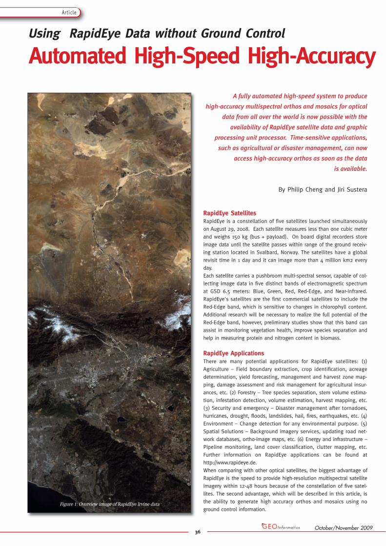
Figure 4: Full resolution orthorectified RapidEye Phoenix data corrected without GCPs overlaid with USGS 1:24000 vectors
Irvine, CaliforniaThe data has a coverage of approximately 76 km by 230 km. Figure 1shows an overview of the image. 14 GCPs were collected from USGS1:24000 scale maps and 0 order RPC adjustment was used. The rootmeans square (RMS) GCP residuals were about 3.6m in X and 7.0m in Ywith a maximum residual of 6.5m in X and 11.5m in Y. The results weresimilar when using 1st order RPC adjustment. When all the GCPs werechanged to independent check points (ICPs), the RMS ICP errors wereabout 5.7m in X and 7.5m in Y witha maximum error of 11.7m in X and13.6m in Y. Although the errors areslightly higher when no GCPs wereused, the RMS errors are still closeto the resolution of the sensor, i.e.,6.5m. The accuracy of the GCPsusing 1:24000 scale maps could alsocontribute the errors in the result.Figure 2 and 3 show examples of theorthorectified image corrected with-out GCPs overlaid with 1:24000USGS vectors and Google Earth,respectively.
Phoenix, ArizonaA block of three 1B RapidEye dataset with overlaps was tested in thiscase. Each image has a coverage
of approximately 76 km by 162 km. 14 DGPS GCPs with sub-meteraccuracy were collected from the data set. The RMS GCP residuals wereabout 2.3m in X and 2.1m in Y with a maximum residual of 3.3m in Xand 4.7m in Y. When all the GCPs were changed as ICPs, the RMS ICPerrors were 3.5m in X and 4.2m in Y with a maximum error of 6.3m inX and 6.5m in Y. Hence, RMS errors when no GCPs were used are with-in the resolution (6.5m) of the sensor in this case. Figure 4 and 5 showexamples of the orthorectified image corrected without GCPs overlaid
with 1:24000 USGS vectors andGoogle Earth, respectively.
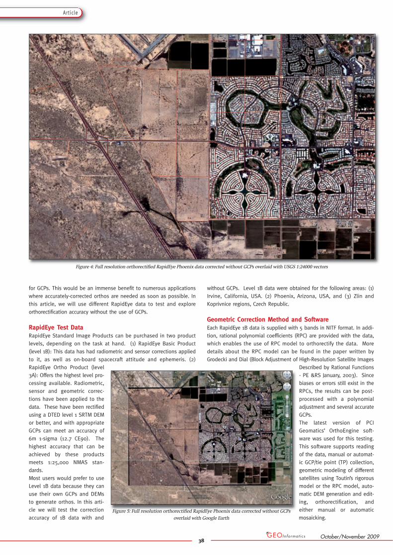
Czech, RepublicRapidEye 1B data set of Zlin andKoprivnice regions were acquiredon June 14, 2009. The size of eachscene was around 76 km by 60 km.The GCPs were collected from 0.5maerial orthophotos and elevationsof GCPs were extracted from DEMthat was generated using 2m con-tours originated from 1:10 000 topo-graphic maps. For testing purposesmore than 30 GCPs were preparedfor each scene. The 1st order of RPCadjustment was used for all scenes.In the case of scene acquired overZlin region 34 GCPs were collected.
Latest News? Visit www.geoinformatics.com
Art ic le
39October/November 2009
Figure 6: Full resolution orthorectified RapidEye Zlin data corrected without GCPs overlaid with Google Earth
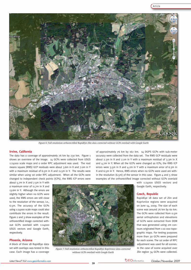
Figure 7: Full resolution orthorectified RapidEye Koprivnice data corrected without GCPs overlaid with Google Earth
The RMS GCP residualswere about 2.0m in Xand 1.9m in Y with amaximum residual of5.4m in X and 4.4m inY. When all the GCPswere changed to ICPs,the RMS ICP errorswere about 3.7m in Xand 4.6 m in Y with amaximum error of 6.6min X and 9.5m in Y.
In the case of sceneacquired over Kopriv -nice region 30 GCPswere collected. TheRMS GCP residualswere about 2.6m in X and 2.3m in Y with a maximum residual of 5.8min X and 5.4m in Y. When all the GCPs were changed to ICPs, the RMSICP errors were about 5.1m in X and 3.9m in Y with a maximum errorof 10.5m in X and 8.6m in Y.
Hence, both data have RMS error within the resolution of the sensorwhen no GCPs were used. Figure 6 and 7 show the orthorectified imagesusing no GCPs overlaid with Google Earth.
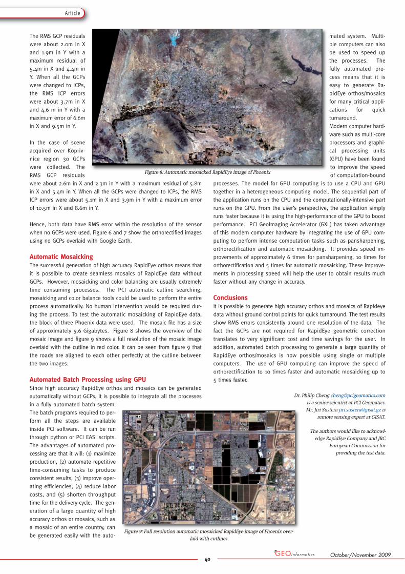
Automatic MosaickingThe successful generation of high accuracy RapidEye orthos means thatit is possible to create seamless mosaics of RapidEye data withoutGCPs. However, mosaicking and color balancing are usually extremelytime consuming processes. The PCI automatic cutline searching,mosaicking and color balance tools could be used to perform the entireprocess automatically. No human intervention would be required dur-ing the process. To test the automatic mosaicking of RapidEye data,the block of three Phoenix data were used. The mosaic file has a sizeof approximately 5.6 Gigabytes. Figure 8 shows the overview of themosaic image and figure 9 shows a full resolution of the mosaic imageoverlaid with the cutline in red color. It can be seen from figure 9 thatthe roads are aligned to each other perfectly at the cutline betweenthe two images.
Automated Batch Processing using GPUSince high accuracy RapidEye orthos and mosaics can be generatedautomatically without GCPs, it is possible to integrate all the processesin a fully automated batch system.The batch programs required to per-form all the steps are availableinside PCI software. It can be runthrough python or PCI EASI scripts.The advantages of automated pro-cessing are that it will: (1) maximizeproduction, (2) automate repetitivetime-consuming tasks to produceconsistent results, (3) improve oper-ating efficiencies, (4) reduce laborcosts, and (5) shorten throughputtime for the delivery cycle. The gen-eration of a large quantity of highaccuracy orthos or mosaics, such asa mosaic of an entire country, canbe generated easily with the auto-
mated system. Multi -ple computers can alsobe used to speed upthe processes. Thefully automated pro-cess means that it iseasy to generate Ra -pid Eye orthos/mosaicsfor many critical appli-cations for quickturnaround. Modern computer hard-ware such as multi-coreprocessors and graphi-cal processing units(GPU) have been foundto improve the speedof computation-bound
processes. The model for GPU computing is to use a CPU and GPUtogether in a heterogeneous computing model. The sequential part ofthe application runs on the CPU and the computationally-intensive partruns on the GPU. From the user’s perspective, the application simplyruns faster because it is using the high-performance of the GPU to boostperformance. PCI GeoImaging Accelerator (GXL) has taken advantageof this modern computer hardware by integrating the use of GPU com-puting to perform intense computation tasks such as pansharpening,orthorectification and automatic mosaicking. It provides speed im -prove ments of approximately 6 times for pansharpening, 10 times fororthorectification and 5 times for automatic mosaicking. These improve-ments in processing speed will help the user to obtain results muchfaster without any change in accuracy.
ConclusionsIt is possible to generate high accuracy orthos and mosaics of Rapideyedata without ground control points for quick turnaround. The test resultsshow RMS errors consistently around one resolution of the data. Thefact the GCPs are not required for RapidEye geometric correction translates to very significant cost and time savings for the user. Inaddition, automated batch processing to generate a large quantity ofRapidEye orthos/mosaics is now possible using single or multiple computers. The use of GPU computing can improve the speed oforthorectification to 10 times faster and automatic mosaicking up to 5 times faster.
Dr. Philip Cheng [email protected] a senior scientist at PCI Geomatics. Mr. Jiri Sustera [email protected] is
remote sensing expert at GISAT.
The authors would like to acknowl-edge RapidEye Company and JRC
European Commission for providing the test data.
40
Art ic le
October/November 2009
Figure 8: Automatic mosaicked RapidEye image of Phoenix
Figure 9: Full resolution automatic mosaicked RapidEye image of Phoenix over-laid with cutlines