Embed Size (px)
Citation preview

ARTICLE 9: ENGINE TECHNICAL REGULATION.rgv2.A9
9. Technical Specification (within the engine seal) for ROTAX kart engines
125 Junior MAX/evo 125 MAX/evo 125 MAX DD2/evo
9.1. Squish gap
125 Junior MAX/evo minimum = 1,20 mm 125 MAX/evo minimum = 1,00 mm 125 MAX DD2/evo minimum = 1,30 mm The squish gap must be measured with a certified slide gauge and by using a 2 mm tin wire (Rotax part no. 580 130). The crankshaft must be turned by hand slowly over top dead center to squeeze the tin wire. The squish gap must be measured on the left and right side in the direction of the piston pin. The average value of the two measurements counts.
9.2. Combustion chamber insert
Cast identification code has to be "223 389" or "223 389 1" or "223 389 2" or 223 389 2/1" or “223 389 2/2”. Casted wording "ROTAX" and/or "MADE IN AUSTRIA" must be shown.
Heights of combustion chamber insert have to be 27,55 mm with a tolerance of +0,0/-0,1 mm (A) A B and 28,80 mm with a tolerance of +/- 0,2 mm (B).
The CIK-FIA Technical regulation also applies for the Rotax Winter Cup, Rotax Euro Challenge & Rotax International Open. The English text is the authentic version. RGMMC reserves the right to issue additional statements concerning the Technical Regulations (previously approved by the ASN proposing the series and the CIK-FIA from time to time following the agreement of the ASN presenting the series
and the CIK-FIA, and all such statements will be issued to all registered competitors by way of Competitors’ Bulletins at the race meeting, or posted to the address detailed on the Event/Series Registration Form.
2015 ROTAX WINTER CUP © 2015 ROTAX EURO CHALLENGE ©
2015 ROTAX INTERNATIONAL OPEN ©

The profile of the combustion chamber insert has to be checked with a template (ROTAX part no. 277 390). The crack of light between the template and the profile of the combustion chamber insert has to be the same over the whole profile.
9.3. Piston with ring assembly
Original, coated, aluminum, cast piston with one piston ring. The piston has to show on the inside the cast wording "ELKO" (1) and "MADE IN AUSTRIA" (2). Machined areas are: Top end of piston, outside diameter, groove for the piston ring, bore for the piston pin, inside diameter at bottom end of piston and some pre-existing factory removal (3) of flashing at the cut out of the piston skirt. All other surfaces are not machined and have cast surface. Any mechanical treatment or rework of the piston is forbidden, (e.g. removal of carbon deposits). Cleaning without changing the original surface is allowed.
Original, magnetic, rectangular piston ring. Ring height : 0,98 +/- 0,02 mm. Piston ring is marked either with "ROTAX 215 547" or "ROTAX 215 548".
9.4. Piston pin
Piston pin is made out of magnetic steel. Dimensions must be according to the drawing. The minimum weight of the piston pin must not be lower than 32,10 grams.
9.5. Cylinder Light-alloy-cylinder with GILNISIL-plating. Any re-plating of cylinder is not allowed. Maximum bore of cylinder = 54,035 mm (measured 10 mm above the exhaust port). Cylinder has to be marked with the "ROTAX" logo (see pictures below).
125 JUNIOR MAX Cylinder with one main exhaust port but without exhaust valve. Cylinder has to be marked either with identification code 223 994, 223 998 or 223 999
125 SENIOR MAX
Cylinder with one main exhaust port and exhaust valve. Cylinder has to be marked either identification code 223 993, 223 996 or 223 997

125 MAX DD2 Cylinder with one main exhaust port and two side exhaust ports and exhaust valve. Cylinder has to be marked either identification code 613 933, 613 931 or 613 930
Height of cylinder (measured with a digital caliper min. length 200mm). 125 Junior MAX and 125 MAX: 87,00 mm -0,05/+0,1 mm125 MAX DD2: 86,70 mm -0,05/+0,1 mm
Cylinder surfaces
All transfer ports and passages have cast finish surface except some removal (done by the manufacturer) of cast burr at the inlet passage, exhaust port and passages. All ports have chamfered edges to prevent ring snagging. Any additional machining is not permitted. The top edge of exhaust port may show some pre-existing machining from the manufacturer. The sealing flange for the exhaust socket may show signs of machining from the manufacturer.
All ports have chamfered edges. Any additional machining is not permitted.
Cylinders marked 223 993, 223 994 and 613 933 the upper edge of the central boost port may show factory machining.
The flange for the exhaust socket may show either cast finish or
machined surface.
Machined surface can be either flat or show a circular sealing bump.
Picture is for example of sealing flange surface finish only and does not depict the shape of Senior or Junior exhaust port

The top edge of the exhaust port may show either just a cast finish surface (left picture) or signs of a CNC machining (central picture) or signs of CNC machining in combination with signs of manual grinding (right picture).
The exhaust port may show partial manual grinding done by the manufacturer to eliminate minor casting defects and/or to eliminate the NIKASIL burr at the end of the NIKASIL plating (right picture).
Exhaust port timing The "exhaust port timing" (distance from the top of the cylinder to the top of the exhaust port) has to be checked by means of the template (ROTAX part no. 277 397). Insert the template (take care to use the correct gauge JUN, MAX, DD2) into the cylinder, that the template is touching the cylinder wall and that the finger of the template is located in the middle of the exhaust port (highest point). Move the template upwards, until the finger is touching the top edge of the exhaust port. Insert a filler gauge between the top of the cylinder and the template. It must not be possible to fit the feeler gauge specified below.
125 Junior MAX Cylinder 223 999/998: Cylinder 223 994:
125 MAX Cylinder 223 993/996/997:
0,90 mm 1,10 mm
0,75 mm
At cylinders 223 993 the cylinder is also legal if the template doesn´t fit in at all.
125 MAX DD2 Cylinder 613 933/931/930:
0,75 mm
At cylinders 613 933 the cylinder is also legal if the template doesn´t fit in at all.
Exhaust valve (125 MAX and 125 MAX DD2)
If the piston is moved in direction top of cylinder and first time covering completely the exhaust port, it must be possible to insert the exhaust valve gauge (Rotax part no. 277 030) until it stops at the surface of the cylinder (a feeler gauge of 0,05 mm must not be possible to fit in at any area around). Modifying the gasket (Rotax part no. 250 231) between the cylinder and the exhaust valve housing is illegal.

9.6. Inlet system Inlet manifold is marked with the name "ROTAX" and the identification code“267 915” 125 Junior MAX and 125 MAX .“267 410” 125 MAX DD2. Some factory flash removal may be present at the conjunction of the inside contour and the carburetor stop mounting face. This is a manual trimming operation consisting of a small corner break of less than 3 mm in width. No additional grinding or machining is permitted.
The reed valve assy. is equipped with 2 petal stops and 2 reeds, each having 3 petals. The thickness of the reeds is 0,6 mm +/- 0,10 mm.
9.7. Crankshaft
Stroke 54,5 mm +/-0,1 mm Con rod has to show forged numbers "213", "365", "367" or “362” on shaft. Shafts of con rods "213", "365" and "367" are not machined and are copper plated. Shaft of con rod “362” is not copper plated and blank (grey). Grinding or polishing of shaft of con rod is not permitted.
9.8. Crankshaft main bearings Crankshaft main bearing 6206 from FAG is allowed only. (must be marked with code 579165BA or Z-579165.11.KL)
9.9. Balance shaft (125 Junior MAX and 125 MAX) Balance shaft and balance gears must be installed. Configurations of part no. 237 949 (equal with 237 948) only is legal. Surface (1) is not machined and must show cast surface. Measurement from center of balance shaft to outer diameter of fly weight of balance shaft at defined length must not be lower than specified. The minimum weigh of the dry balance shaft must not be lower than: 255 grams for balance shaft ROTAX part no. 237 949 (equal with 237 948).
9.10. 2-speed gearbox (125 MAX DD2) Primary shaft with 19 teeth for 1st gear and 24 teeth for 2nd gear. Idle gear for 1st gear has to have 81 teeth. Idle gear for 2nd gear has to have 77 teeth

9.11. Crankcase As supplied by the manufacturer. No grinding/polishing is permitted in the two main transfer passages as well as in the crank area. Uncoated as well as black coated crankcases are legal to be used.
9.20. Technical Specification (outside the engine seal) for ROTAX kart engines 125 Junior MAX/evo 125 MAX/evo 125 MAX DD2/evo
It is the responsibility of the competitor to check his equipment (all components outside the engine seal as mentioned below), to assure that his equipment is conforming to the technical specification below!
9.21. Balance drive (125 Junior MAX and 125 MAX)
Only steel balance gears are legal to be used. Balance gears must be installed and must be aligned according to the instruction in the repair manual. Mixing of steel balance gears of different width (6,0 and 9,0 mm) is strictly forbidden.
Balance drive (125 MAX DD2)
Balance drive gear must be fitted on crank shaft. Balance gear must be fitted on primary shaft and must be aligned with the balance drive gear according to the instruction in the repair manual. Version 1: Fly weight of balance gear must show cast surface
Version 2: Fly weight of balance gear can show machined surface. Dimension A (widest part of balance weight) must be either 53,0 mm +/- 0,5 or 57,0 mm +/- 0,5 The minimum weight of a dry balance gear including bearing must not be lower than 240 grams.
9.22. Centrifugal clutch
125 Junior MAX and 125 MAX Engagement speed of centrifugal clutch at maximum 4.000 rpm (the kart without driver must start to move). Both versions of clutch (item 3, with and without holes) are legal to be used. O-ring (item 10) must be fitted and must assure an appropriate sealing between the clutch drum and the needle/plain bearing.
Signs of emission of grease from the needle/plain bearing into the clutch drum may not exceed the picture beside. Contact area between clutch and clutch drum has to be dry at any time – no lubrication allowed.

125 MAX DD2 Engagement speed of centrifugal clutch at maximum 4.000 rpm
(the kart without driver must start to move). Both versions of clutch (item 6, with and without holes) are legal to be used. O-ring (item 11) must be fitted.
Height of clutch 125 Junior MAX and 125 MAX: Minimum = 11,45 mm 125 MAX DD2: Minimum = 14,45 mm
Thickness of clutch shoe Minimum = 24,10 mm Measurement has to be done at the 3 open ends of the clutch,. 5 - 10 mm from the machined groove (all clutch shoes must be completely closed at measurement - no gap).
Outer diameter of clutch drum Minimum = 89,50 mm Diameter has to be measured with a sliding caliper just beside the radius from the shoulder (not at the open end of the clutch drum).
Inner diameter of clutch drum Maximum = 84,90 mm The inner diameter has to be measured with a sliding caliper. The measurement has to be done in the middle of the clutch drum (in the contact area between clutch and clutch drum).

Height of clutch drum with sprocket/primary gear 125 Junior MAX and 125 MAX Minimum = 33,90 mm 125 MAX DD2 Minimum = 39,50 mm
9.23. Primary drive (125 MAX DD2):
Original primary drive gears of following gear ratio options must be used only. Following combinations are legal to be used. Drive gear Driven gear 32 65 33 64 34 63 35 62 36 61 37 60 38 59 A specific primary gear ratio may be determined for each race event by a “Bulletin”.
9.24. Gear shifting (125 MAX DD2)
The 2-speed gearbox has to be operated from the steering wheel via two bowden cables. To versions of original paddle shift systems are legal to be used.
Version 1, plastic shift paddles Cutting of the original plastic shift paddles (item 23) or adding of pads to the shift paddles is allowed to adjust the paddle to specific steering wheels. Original plastic steering wheel hub (item 27, Rotax part no. 660 640) must be used.
Version 2, aluminum shift paddles Cutting of the original aluminum shift paddles or adding of non original parts is not allowed. Mounting the shift paddles (item 31) on the bottom or top side of the whip (item 25) is an allowed adjustment. Optional parts (items 36-38) can be mounted on the shift paddle (item 31) in any position. Bending the aluminum shift paddles to align them to the steering wheel is an allowed adjustment.

9.25. Exhaust valve (125 MAX and 125 MAX DD2) Two versions of original exhaust valve systems (pneumatic/electronic timed) are legal to be used. Both systems have to be used as supplied with all components fitted. Length of the exhaust valve (item 4 of pneunatic timing, item 2 of electronic timed exhaust valve) is 36,5 mm +0,20 mm/-0,30 mm. Width of collar is 4,8 mm +/-0,3 mm Green colored exhaust bellow (item 11 of pneumatic timed exhaust valve, item 10 of electronic timed exhaust valve, Rotax part no. 260 723) only is legal to be used.
Version 1, pneumatic timed exhaust valve. Version 2, electronic timed exhaust valve
9.26. Ignition system
Digital battery ignition, variable ignition timing, no adjustments possible.
Spark plug: DENSO Iridium IW 24 or IW 27 or IW 29 or IW 31 or IW 34
Spark plug cap must be marked with "NGK TB05EMA".
The marking of the pick-up must show the following numbers in the first line 029600-0710. A steel ball (diameter 3-5 mm) placed on circular surface of the sensor must stay in the center of the circular surface.
Two versions of original ignition systems (Denso and Dellorto) are legal to be used.
Race officials may request at any time that the competitor replaces the ignition coil (Denso ignition system)/electronic box (Dellorto ignition system) with another unit provided by the race administration.

Version 1, Denso ignition system The casting of the ignition coil has to show the following in casting "129000-" and "DENSO".
125 Junior MAX and 125 MAX Ignition coil must show 3 pins at the terminal. Connector housing of ignition coil must have either black or green color Version with extension wire (number 265571 engraved as in picture) is not legal to be used any more as of 01.03.2012. Minimum length of the high tension cable is 210 mm (from outlet of ignition coil to outlet of spark plug connector = visible length of cable).
The ignition coil has to be fixed by means of 2 original silent blocks to the gearbox cover. In case a chassis component collides with the ignition coil, it is an allowed modification to use a supplementary extension bracket (rigid, solid metal, mounted at the original fixation holes of the gearbox cover) to avoid any collide.
To fit a second original mass cable (ROTAX part no. 264 910) is an allowed option
125 MAX DD2
Ignition coil must show 4 or 6 pins at the terminal. Connector housing of ignition coil must have either white or grey color. Also ignition coils marked with number "266 750" are legal to be used.
Minimum length of the high tension cable is 210 mm (from outlet of ignition coil to outlet of spark plug connector = visible length of cable).
The ignition coil has to be fixed by means of 2 original silent blocks to the left side of the crankcase.
Mounting the ignition coil on the optional bracket (Rotax part no. 651 055) to the clutch cover is an allowed option.
To fit a second original mass cable (ROTAX part no. 264 910) is an allowed option

Version 2, Dellorto ignition system Ignition coil (same for all engines) with separate electronic box (ECU, specific for every engine).
Ignition coil and electronic box have to be fitted by means of the corresponding brackets and components according to the illustration (top illustration 125 Junior MAX and 125 MAX, bottom illustration 125 MAX DD2).
The visual appearance of the ignition coil must be identical with the pictures. Ignition coil must show 2 pins at the terminal. The ignition coil is labeled with two stickers, “BRP 666820” and “NIG 0105”. The ignition coil is still legal to be used also if one or both stickers disappeared. Minimum length of the high tension cable of the ignition coil is 210 mm (from outlet of ignition coil to outlet of spark plug connector = visible length of cable.
The ground cable of the cable harness has to be connected to the engine at the rear, left Allen screw of the cylinder head cover.
The electronic boxes are labeled with stickers and are still legal also if the sticker disappeared. 125 Junior MAX: “666812, 125 Junior MAX evo” 125 MAX: “666814, 125 MAX evo” 125 MAX DD2: “666816, 125 MAX DD2 evo” The electronic box has to be checked with the ECU tester (Rotax part no. 276 230) according to following procedure. Disconnect engine cable harness from electronic box. Connect ECU tester cable harness to electronic box. Connect energy cable of ECU tester cable harness with the charging connector of engine cable harness. The ECU tester will automatically detect the type of the ECU and will start a check program for the ignition timing and the timing for the exhaust valve. The ECU tester has to show following results:
125 Junior MAX
ECU TEST OK 125 Junior MAX evo
125 MAX ECU TEST OK 125 MAX evo
125 MAX DD2 ECU TEST OK 125 MAX DD2 evo

9.27. Battery, battery fixation Original batteries with following specification only are legal to be used. YUASA YT7B-BS (with and without Rotax branding) ROTAX RX7-12B or RX7-12L (lithium iron phosphate type)
Battery must be fitted with the original battery clamp and battery cover (both versions left and right are legal) and must be fixed to the chassis with both clamps (all 4 screws).
Battery clamp must be mounted on the left side of the seat (valid for both versions).
9.28. Intake silencer 125 Junior MAX and 125 MAX Intake silencer with integrated, washable air filter has to be used with all parts as shown at the illustration and has to be mounted on the support bracket with two screws (in dry and wet condition).
Intake silencer tube (pos 2) and carburetor socket (pos 6) are marked with the wording "ROTAX". Intake silencer case bottom is marked on the inside with the Rotax part no. 225 015. Intake silencer case, top is marked on the inside with the Rotax part no. 225 025.
Air filter (pos 4) must be installed as shown in the illustration between the two holders (pos 3) and must cover the complete area of the intake silencer case bottom (pos1).
Also at wet condition it is not allowed to attach anything to the air box to protect the air inlet from water spray.

125 MAX DD2 Intake silencer with integrated washable air filter as shown in illustration. The intake silencer case (pos 1) is marked on the inside with the Rotax part no. 225 012 (4 clips) or 225 013 (5 clips). The intake silencer cover (pos 2) is marked on the inside with the Rotax part no. 225 022 (4 clips) or 225 023 (5 clips). Two versions of air filters (pos 3) are legal to be used. Version 1, with integrated steel frame. Version 2, with separate plastic frame (pos 4). The air filter must be assembled between the intake silencer case and the intake silencer cover that the whole area of the intake silencer case is covered. At intake silencer cover (pos. 2, Rotax part no. 225 022), it is mandatory to fit the O-ring (pos. 6) on the intake silencer tube (pos. 5). Sealing the top of the airbox using adhesive tape is an allowed modification. Also at wet condition it is not allowed to attach anything to the air box to protect the air inlet from water spray.
9.29. Carburetor
Dellorto carburetor, housing has to show the cast wording “VHSB 34” Carburetor housing is stamped either with “QD”, “QS” or “XS”. The complete inlet bore of the carburetor must show cast surface. Optional carburetor plug screw marked "ROTAX" (ROTAX part no. 261 030) is legal to be used. The two vent fittings must be connected with the original air vent hose min 155 mm (Rotax part no. 260 260). The location of the opening has to be placed at the rear side of the carburetor Settings of the carburetor adjustment screws (idle and idle air) are free. The position of the jet needle is free. All jets must be correctly seated and securely fitted at any time (tightened)! A minimum required size of main jet may be determined for each race event by a “Bulletin”.
The height of the two arms of the float lever must be within the slot of the carburetor gauge (Rotax part no. 277 400) by their normal weight measured at carburetor housing without gasket in reverse upright position.
Needle valve assembly stamped "150" Needle of needle valve marked with diamond symbol ”INC" only.
Start jet is stamped with the digits “60”.

Specific regulation for Dellorto VHSB 34 QS and QD Carburetor slide shows digits “40” in casting. Jet needle must be stamped with “K98”. Two floats marked "3,6 gr" or “5,2 gr” are legal to be used only (valid for 125 Junior MAX and 125 MAX). Two floats marked “5,2 gr” are legal to be used only (valid for 125 MAX DD2).
Needle jet Stamped with ”FN 266” Total length: 54,00 +/- 0,3 mm Length of bottom section: 11,50 +/- 0,2 mm
Top bore diameter 2,60 +/- 0,15 mm (measured 2 mm inside)
4 x4 cross holes diameter: Plug gauge 0,90 mm may not enter one of the 16 cross holes (use jet gauge set Rotax part no. 281 920).
Idle jet Idle jets stamped 30, 35, 40, 45, 50, 55 and 60 only are legal to be used. It is not mandatory that idle jet and idle emulsion tube show the same size. Plug gauge 0,65 mm may not enter the bore of the idle jet 60 (use jet gauge set Rotax part no. 281 920).

Idle emulsion tube: Idle emulsion tube stamped 30, 35, 40, 45, 50, 55 and 60 are legal to be used. It is not mandatory that idle emulsion tube and idle jet show the same size. Plug gauge 0,65 mm may not enter the bore (use jet gauge set Rotax part no. 281 920).
Plug gauge 0,65 mm may not enter one of the 4 cross bores (use jet gauge set Rotax part no. 281 920).
Carburetor insert Carburetor insert must show stamping "8.5"
Angular bore of carburetor insert Plug gauge 0,60 may not enter the bore (use jet gauge set Rotax part no. 281 920).
Vertical bore of carburetor insert Plug gauge 0,90 may not enter into bore (use jet gauge set Rotax part no. 281 920).
0,90

Atomizer Remove atomizer from carburetor body by means of venturi tool set (Rotax part no. 676 034); Atomizer, total length: 23,75 +/- 0,45 mm
Atomizer, length of cylindrical part: 15,75 +/- 0,25 mm
Atomizer, dimension of cutaway: 6,00 +/- 0,15 mm
Atomizer, diameter of cross bore: 4,05 +/- 0,15 mm
Optional items Rotax part no. 240 184 (2 x Allen screw) and Rotax part no. 261 552 (1 x main jet cup) are legal to be used. These parts optionally replace the parts 262 020 and 261 550 in the case of sealing a carburetor.

Specific regulation for Dellorto VHSB 34 XS Carburetor slide shows digits “45” in casting. Jet needle must be stamped with “K57”. Two floats marked "4,0 gr" are legal to be used only Idle has to be stamped with “60”. Idle emulsion tube has to be stamped with “45”
Needle jet Stamped with ”DP267” Total length: 51,0 +/- 0,3 mm
Length of bottom section: 33,0 +/- 0,2 mm
Carburetor insert must show stamping “12,5”

9.30. Fuel pump, fuel filter MIKUNI diaphragm pump, (see picture) must be used and must be mounted as shown in the illustration.
125 Junior MAX and 125 MAX Fuel pump must be mounted on the bottom side of the support bracket for the intake silencer (left illustration).
125 MAX DD2 Fuel pump must be mounted on the support bracket, marked 651 055, attached to the clutch cover (right illustration). Mounting the fuel pump with the two original rubber buffers to the chassis is an allowed option. In this case the fuel pump must be mounted below the inlet center line of the carburetor.
Fuel filter Two versions of original fuel filter are legal to be used (see pictures) Except the fuel line, the fuel pump and the original fuel filter no additional parts are legal to be mounted between fuel tank and carburetor.
9.31. Radiator The removal of the thermostat from the cylinder head cover is an allowed modification. Radiator must be mounted with all components as shown in the respective illustration. To apply tape (neutral tape without advertising only) around the radiator is an allowed modification to control the air flow through the radiator. Tape may not be removed from the radiator during operation on the track. Any other non original device to control the air flow through the radiator is prohibited.
125 Junior MAX and 125 MAX
The radiator has to be mounted on the right side of the engine. Three different versions as shown in the illustrations are legal to be used.
Version 1 Cooling area: Height = 290 mm, width = 133 mmThickness of radiator: 32 mm

Version 2 Cooling area: Height = 290 mm, width = 133 mm Thickness of radiator: 32 mm The support plate (pos. 7) enables two different mounting positions (height) of the radiator. Both mounting positions are legal to be used.
Version 3 Cooling area: Height = 290 mm, width = 138 mm Thickness of radiator: 34 mm Radiator must be stamped on the side with the wording “ROTAX”. To remove the original flap is an allowed modification.
125 MAX DD2 The radiator has to be mounted on the left side of the driver seat. The highest point of the radiator with cap may not be higher than 400 mm above the main tube of the kart chassis. Two different versions as shown in the illustrations are legal to be used.
Version 1 Cooling area: Height = 284 mm, width = 202 mm Thickness of radiator: 32 mm
Version 2 Cooling area: Height = 290 mm, width = 196 mm Thickness of radiator: 34 mm To remove the original flap is an allowed modification.

9.32. Engine coolant Plain water without any additives has to be used.
9.33. Exhaust system Two versions of original exhaust sockets are legal to be used. Version 1, without gasket ring (left illustration) Version 2 with gasket ring (right illustration) At version 2 the measurement (C) must be at least 15,5 mm.
The use of maximum 4 pieces of original Rotax exhaust springs, to fix the exhaust system to the cylinder is allowed. (a “safety wire” in the exhaust flange area is not allowed).
Original exhaust system as supplied by Rotax is mandatory to be used. Welding at the exhaust system is only allowed in the case of a repair. Allowed modifications on the original exhaust systems are: ► Replacing the original rivets of the silencer end cap by 4 mm metric screws and corresponding locking nuts. ► Replacing the isolating mat (just one original isolating mat may be fitted) inside the silencer and the silencer end cap with perforated tube by original Rotax spares parts. ► Welding a socket (in a distance of 50-80 mm from the ball joint) on the top of the exhaust system for measuring the exhaust gas temperature. ► Addition extra elements after the original silencer for further noise reduction. ► Additional to the standard isolation mat a steel isolation mat (Rotax part no. 297 983) of the square dimension of 165 +10 mm is legal (not mandatory) to be assembled underneath the standard isolation mat according to the illustration. Clamp (1) must be fitted at a distance of 18+/-2mm, measured from the end of the tube. Clamp (2) must be fitted at the end area of the steel isolation mat. The measurement 10-12 mm from the end of the perforated tube to the beginning of the steel isolating mat is a specification for assembly purpose only! Both clamps (1 and 2) are mandatory to be fitted and tightened.
125 Junior MAX and 125 MAX Three versions of exhaust systems are legal to be used.
Version 1, tuned pipe and silencer are one piece. The silencer is welded to the 180° elbow and the tuned pipe (top illustration). Version 2, tuned pipe and silencer are one piece. The silencer is welded to the 180° elbow. Two springs fix the silencer to the tuned pipe (bottom illustration). Following measurements are valid for version 1 and 2: Silencer end cap, diameter of hole: 21,0 mm (maximum). Length of inlet cone: 592 mm +/-5 mm (measured on outside from beginning of exhaust pipe until beginning of cylindrical part). Length of cylindrical part of exhaust pipe: 125 mm +/-5 mm. Length of end cone: 225 mm, +/-5 mm. Outside diameter of 180° bent tube: 41mm +1,5 mm/–1,0 mm (measured at beginning and end of bend).
Version 3, tuned pipe with 180° elbow and silencer are two separate pieces. The silencer is fixed with 2 springs to the 180° elbow and two springs to the tuned pipe. The silencer can be turned that the 90° elbow outlet of the silencer shows either downwards towards the asphalt (preferred version for lowest noise emissions) or towards the back.
It is also allowed to use the silencer end cap (without 90° elbow) and perforated tube of version 1 and 2.
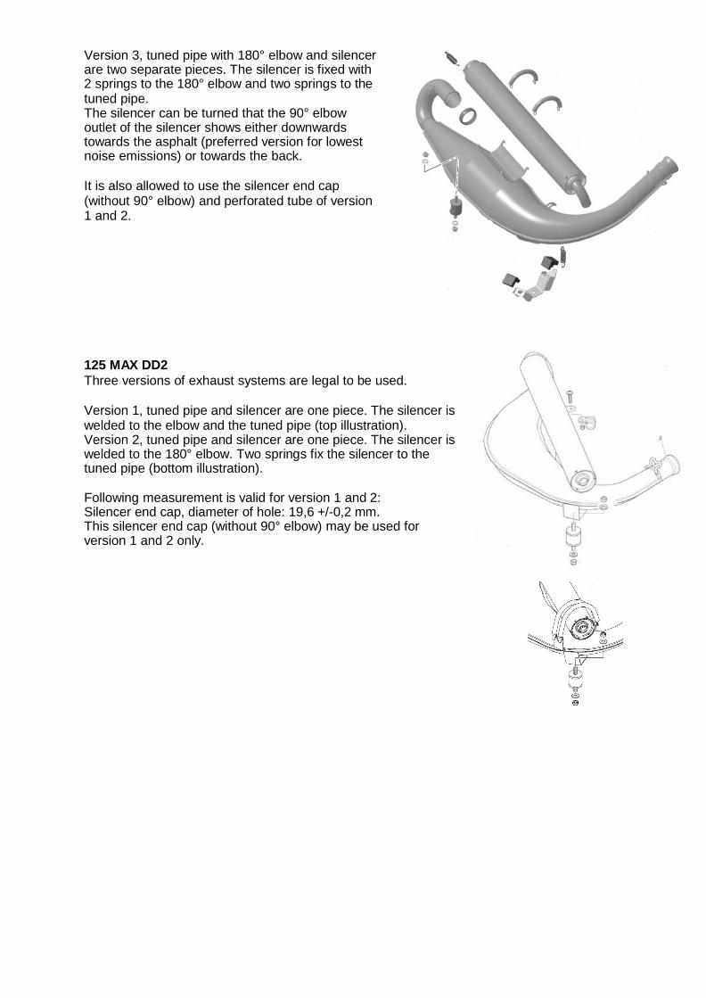
125 MAX DD2
Three versions of exhaust systems are legal to be used. Version 1, tuned pipe and silencer are one piece. The silencer is welded to the elbow and the tuned pipe (top illustration). Version 2, tuned pipe and silencer are one piece. The silencer is welded to the 180° elbow. Two springs fix the silencer to the tuned pipe (bottom illustration).
Following measurement is valid for version 1 and 2: Silencer end cap, diameter of hole: 19,6 +/-0,2 mm. This silencer end cap (without 90° elbow) may be used for version 1 and 2 only.

Version 3, tuned pipe with 180° elbow and silencer are two separate pieces. The silencer is fixed with 2 springs to the 180° elbow and two springs to the tuned pipe. The silencer can be turned that the 90° elbow outlet of the silencer shows either downwards towards the asphalt (preferred version for lowest noise emissions) or towards the back. Silencer end cap with 90° elbow is mandatory to be used for version 3.
9.34. Additional seat support (125 MAX DD2)
On the engine side maximum one additional seat support is allowed to be used. The additional seat support must be fastened to the engine using the threaded hole designed for this purpose.