Embed Size (px)
Citation preview

nearly identical, and both contain information that’s per-tinent to electrical installations. This includes mounting heights for things such as receptacles, switches, and ther-mostats, as well as limitations on protruding objects like wall sconce luminaires.
If you’re in a wheelchair, you’re obviously limited by how far you can reach. Due to this, receptacles and switches must be mounted between 15 in. and 48 in. above the floor, generally speaking (see Annex J for more detailed require-ments). What if you’re visually impaired and use a cane to assist you? One of the more dangerous things that you could encounter is an object that sticks out from the wall (like a wall sconce) that’s mounted high enough that your cane won’t detect it, but low enough your face will! For this reason, objects must only stick out from the wall 4 in. if that object is mounted between 27 in. and 80 in. above the floor (next time you’re in a commercial building look at how many things violate this, like drinking fountains and fire extinguishers).
Annex J was added to let Code users know of some of these requirements. Annex J is certainly not an all-inclusive list of the requirements for accessibility for disabled per-sons, but it does include the most common requirements about which electricians and electrical engineers need to know.
110.1 Scope
An Informational Note was added to refer Code users to a new Annex.
110.1 Scope. Article 110 covers the general requirements for the examination and approval, installation and use, access to and spaces about electrical equipment; as well as general requirements for enclo-sures intended for personnel entry (manholes, vaults, and tunnels).
Note: See Annex J for information regarding ADA accessibility design.
Author’s Comment: Requirements for people with disabilities include things like mounting heights for switches and recepta-cles, and requirements for the distance that objects such as wall sconces protrude from a wall.
ANALYSIS: Most commercial buildings and some mul-tifamily dwellings need to be constructed to meet the Americans with Disabilities Act. This can be done by fol-lowing the Americans with Disabilities Act Accessibility Guidelines (ADAAG), or the ICC/ANSI A117.1 Accessible and Usable Buildings and Facilities. Municipalities typically choose one or the other to adopt and enforce. Both doc-uments meet the “safe harbor” provision of ADA. They’re
Introduction to Article 110—Requirements for Electrical InstallationsArticle 110 sets the stage for how you’ll implement the rest of the NEC. This article contains a few of the most important and yet neglected parts of the Code. For example:
– How should conductors be terminated? – What kinds of warnings, markings, and identifi cation does a given installation require? – What’s the right working clearance for a given installation? – What do the temperature limitations at terminals mean? – What are the NEC requirements for dealing with fl ash protection?
23Mike Holt Enterprises, Inc. • www.MikeHolt.com • 888.NEC.CODE (632.2633)
ARTICLE
110 REQUIREMENTS FOR ELECTRICAL INSTALLATIONS

Author’s Comments:
• See the definition of “Identified” in Article 100.
• Conductor terminations must comply with the manufac-turer’s instructions as required by 110.3(B). For example, if the instructions for the device state “Suitable for 18-12 AWG Stranded,” then only stranded conductors can be used with the terminating device. If the instructions state “Suitable for 18-12 AWG Solid,” then only solid conductors are permitted, and if the instructions state “Suitable for 18-12 AWG,” then either solid or stranded conductors can be used with the ter-minating device.
Copper and Aluminum Mixed. Copper and aluminum conductors must not make contact with each other in a device unless the device is listed and identifi ed for this purpose.
Author’s Comment: Few terminations are listed for the mixing of aluminum and copper conductors, but if they are, that will be marked on the product package or terminal device. The reason copper and aluminum shouldn’t be in contact with each other is because corrosion develops between the two different metals due to galvanic action, resulting in increased contact resistance at the splicing device. This increased resistance can cause the splice to overheat and cause a fire.
Note: Many terminations and equipment are either marked with a tightening torque or have the torque values included in the product’s instructions.
110.14 Conductor Termination and Splicing
The Informational Note was revised for accuracy.
110.14 Conductor Termination and Splicing. Conduc-tor terminal and splicing devices must be identifi ed for the conductor material and they must be properly installed and used. Figure 110–1
Author’s Comment: Switches and receptacles marked CO/ALR are designed to ensure a good connection through the use of a larger contact area and compatible materials. The terminal screws are plated with the element called “Indium.” Indium is an extremely soft metal that forms a gas-sealed connection with the aluminum conductor.
Connectors and terminals for conductors more fi nely stranded than Class B and Class C, as shown in Table 10 of Chapter 9, must be iden-tifi ed for the conductor class. Figure 110–2
Author’s Comment: According to UL Standard 486 A-B, a terminal/lug/connector must be listed and marked for use with other than Class B stranded conductors. With no marking or fac-tory literature/instructions to the contrary, terminals may only be used with Class B stranded conductors.
Figure 110–1
Figure 110–2
Mike Holt’s Illustrated Guide to Changes to the NEC 201424
110.14 | Requirements for Electrical Installations

information as well, and, if it’s listed equipment, these instructions must be followed [110.3(B)]. Although it wouldn’t be a Code violation to ignore torque values on equipment that isn’t listed, it probably wouldn’t be a good idea to do so. Most electrical fires don’t start in the middle of a raceway; they start at a termination of some sort. The importance of properly torquing terminations can’t possibly be overstated.
110.16 Arc-Flash Hazard Warning
Marking requirements have been relaxed and changes have been made to correlate with other Code changes.
110.16 Arc-Flash Hazard Warning. Electrical equipment such as switchboards, panelboards, industrial control panels, meter socket enclosures, and motor control centers in other than dwelling units that are likely to require examination, adjustment, servicing, or maintenance while energized must be marked to warn qualifi ed per-sons of the danger associated with an arc fl ash from short circuits or ground faults. The marking can be made in the fi eld or the factory, but it must meet the requirements of 110.21(B), and be clearly visible to qualifi ed persons before they examine, adjust, service, or perform maintenance on the equipment. Figure 110–4
Author’s Comment: Conductors must terminate in devices that have been properly tightened in accordance with the man-ufacturer’s torque specifications included with equipment instructions. Failure to torque terminals can result in excessive heating of terminals or splicing devices due to a loose connec-tion. A loose connection can also lead to arcing which increases the heating effect and may also lead to a short circuit or ground fault. Any of these can result in a fire or other failure, includ-ing an arc-flash event. In addition, this is a violation of 110.3(B), which requires all equipment to be installed in accordance with listing or labeling instructions. Figure 110–3
Question: What do you do if the torque value isn’t provided with the device?
Answer: Call the manufacturer, visit the manufacturer’s Website, or have the supplier make a copy of the installation instructions.
Author’s Comment: Terminating conductors without a torque tool can result in an improper and unsafe installation. If a torque screwdriver isn’t used, there’s a good chance the conductors aren’t properly terminated.
ANALYSIS: Many pieces of equipment are, in fact, marked with their tightening torque. This isn’t, however, the only place that one might expect to find this information. The instructions that come with the product may contain this
Figure 110–3
Figure 110–4
25Mike Holt Enterprises, Inc. • www.MikeHolt.com • 888.NEC.CODE (632.2633)
Requirements for Electrical Installations | 110.16

(B) Field-Applied Hazard Markings. Where caution, warning, or danger signs or labels are required, the labels must meet the following:
(1) The markings must use words, colors, or symbols that effectively warn personnel. Figure 110–5
Note: ANSI Z535.4, Product Safety Signs and Labels, provides guide-lines for the design and durability of signs and labels.
(2) The label can’t be handwritten, and it must be permanently affi xed to the equipment. Figure 110–6
Author’s Comments:
• See the definition of “Qualified Person” in Article 100.
• This rule is meant to warn qualified persons who work on energized electrical systems that an arc flash hazard exists so they’ll select proper personal protective equipment (PPE) in accordance with industry accepted safe work practice standards.
Note 1: NFPA 70E, Standard for Electrical Safety in the Workplace, pro-vides assistance in determining the severity of potential exposure, plan-ning safe work practices, arc-fl ash labeling, and selecting personal protective equipment.
ANALYSIS: Since the introduction of this section in 2002, it’s been changed every single Code cycle. The upside is that it seems to improve every three years.
The requirement for the marking to take place in the field has been removed. It seems a bit silly that an instal-lation can pass or fail an inspection based on who put the sticker on the equipment. If the sticker is present, and it provides the necessary information, why should it be noncompliant?
A reference to the new 110.21(B) has also been added. This new requirement contains information about signage in general, and will be discussed further in that section of this textbook.
Lastly, Informational Note 1 has been revised to make the Code user aware of the fact NFPA 70E contains require-ments for arc-flash labeling as well.
110.21 Markings
New requirements for fi eld-applied labels have been added.
110.21 Markings.
(A) Manufacturer’s Markings. The manufacturer’s name, trademark, or other descriptive marking must be placed on all electrical equip-ment and, where required by the Code, markings such as voltage, current, wattage, or other ratings must be provided. All marking must have suffi cient durability to withstand the environment involved.
Figure 110–5
Figure 110–6
Mike Holt’s Illustrated Guide to Changes to the NEC 201426
110.21 | Requirements for Electrical Installations
ANALYSIS: With the addition of 110.21(B), several Coderequirements such as this one have been revised. Section 110.21(B) requires that field-applied labels be perma-nently affixed, be suitable for the environment, and can’t be handwritten. Because there are so many changes that are similar to this, not all of them will be covered in this textbook.
110.24 Available Fault Current
An Informational Note has been added to inform the user of the intent of this requirement.
110.24 Available Fault Current.
(A) Field Marking. Service equipment in other than dwelling units must be legibly fi eld-marked with the maximum available fault cur-rent, including the date the fault current calculation was performed, and be of suffi cient durability to withstand the environment involved. Figure 110–8
Note: The fault current markings required by this section are to ensure compliance with 110.9 and 110.10. They’re not intended to be used for arc fl ash analysis. Arc fl ash hazard information is available in NFPA 70E, Standard for Electrical Safety in the Workplace.
Ex to (2): Labels that contain information that’s likely to change can be handwritten, if it’s legible.
Author’s Comment: A permanently affixed sign would include a sticker, but not a piece of paper taped to the equipment.
(3) The marking must be of suffi cient durability to withstand the envi-ronment involved.
ANALYSIS: In an effort to standardize the marking requirements found in the NEC, this requirement has been added. Certainly most will agree that a typed sign is better than a handwritten one.
There are several changes to the Code that require com-pliance with this section, but even without those changes this rule still applies. For example, 110.16 includes a statement requiring compliance with this section. If that statement weren’t in 110.16, it wouldn’t make this rule optional.
Some of the locations in which this rule applies are 110.16, 110.22, 250.20 (although there’s no reference in that section) 312.8, 404.6, 408.3, and many, many others.
110.22 Identifi cation of Disconnecting Means
This section was revised to require compliance with 110.21(B).
110.22 Identifi cation of Disconnecting Means.
(A) General. Each disconnecting means must be legibly marked to indicate its purpose unless located and arranged so the purpose is evident. The marking must be of suffi cient durability to withstand the environment involved. Figure 110–7
(C) Tested Series Combination Systems. Tested series-rated instal-lations must be legibly fi eld-marked in accordance with 240.86(B) and 110.21(B) to indicate the equipment has been applied with a series combination rating.
Figure 110–7
27Mike Holt Enterprises, Inc. • www.MikeHolt.com • 888.NEC.CODE (632.2633)
Requirements for Electrical Installations | 110.24

the breaker would trip faster than it really would (the higher the fault current, the faster the overcurrent device opens). This false value could ultimately result in a lower level of PPE, and put workers in a dangerous situation.
110.25 Lockable Disconnecting Means
A new section provides the rules for lockable discon-necting means.
110.25 Lockable Disconnecting Means. Where the Coderequires that a disconnecting means is lockable in the open position, the provisions for locking must remain in place whether the lock is installed or not. Figure 110–9
Ex: Locking provisions for cord-and-plug connected equipment don’t need to remain in place without the lock installed.
ANALYSIS: When different Code articles have the same requirements it’s nearly impossible to make them all say the same thing. This is due to the fact that there isn’t just one group of a bunch of guys smoking cigars in a dark room choosing which NEC change proposals pass and which fail. They’re groups of professionals in 19 different Code-Making Panels (CMPs), each of which is responsible for a few NEC articles. For example, CMP-4 reviews all
(B) Modifi cations. When modifi cations to the electrical installation affect the maximum available fault current at the service, the maxi-mum available fault current must be recalculated to ensure the ser-vice equipment ratings are suffi cient for the maximum available fault current at the line terminals of the equipment. The required fi eld marking(s) in 110.24(A) must be adjusted to refl ect the new level of maximum available fault current.
Ex: Field markings aren’t required for industrial installations where conditions of maintenance and supervision ensure that only qualifi ed persons service the equipment.
ANALYSIS: This section requires that the service equip-ment be marked with the maximum available fault current. This value is often determined by employing the “Infinite Buss Primary” method, which is based on having no imped-ance from the utility’s point of generation all the way to the transformer serving the building. This method will ensure that the equipment will be rated to handle any dramatic rise in current from a ground fault or a short circuit, because the value will be artificially high (there’s obviously imped-ance between the point of generation and the transformer supplying the building). Having an artificially high value is perfectly acceptable for sizing equipment, but it’s danger-ous if a person is trying to determine what level of Personal Protective Equipment (PPE) they need to use in order to work on the equipment. By using an artificially high value of available fault current, the results of the calculations used for determining PPE will be wrong. This is because a false (higher than reality) value of available fault current means
Figure 110–9
Figure 110–8
Mike Holt’s Illustrated Guide to Changes to the NEC 201428
110.25 | Requirements for Electrical Installations

Table 110.26(A)(1) Working Space
Voltage-to-GroundCondition
1Condition
2Condition
3
0–150V 3 ft 3 ft 3 ft
151–600V 3 ft 3½ft 4 ft
• Condition 1—Exposed live parts on one side of the working space and no live or grounded parts, including concrete, brick, or tile walls are on the other side of the working space.
• Condition 2—Exposed live parts on one side of the working space and grounded parts, including concrete, brick, or tile walls are on the other side of the working space.
• Condition 3—Exposed live parts on both sides of the working space.
(a) Rear and Sides. Working space isn’t required for the back or sides of assemblies where all connections and all renewable or adjustable parts are accessible from the front. Figure 110–11
(b) Low Voltage. If special permission is granted in accordance with 90.4, working space for equipment that operates at not more than 30V ac or 60V dc can be less than the distance in Table 110.26(A)(1). Figure 110–12
Author’s Comment: See the definition of “Special Permission” in Article 100.
of the proposals for Articles 225 and 230, while CMP-9 covers 312, 314, 404, 408, 450, and 490. It makes sense that the rules in Part II of Article 225 are almost identical to those in Article 230—the same people are responsible for both articles. The rule requiring a disconnect in Article 450 (CMP-9) is probably not going to say the same thing as the rule in Article 210 (CMP-2). The rules for equipment requiring a disconnect run the entire gamut of the Code-Making Panels. In order for all of the rules to say the same thing, you have to have one rule, and it has to cover every-thing. This new rule will hopefully satisfy this goal.
The exception to this rule is a rather obvious one, but I guess the NEC has to include it. A lock installed over the end of a cord is an effective way to ensure worker safety. It obviously can’t remain in place at all times, unless you never want to use the equipment again!
110.26 Spaces About Electrical Equipment
Changes have been made to the door hardware requirements for large equipment, and outdoor ded-icated electrical space provisions have been added.
Part II. 600V, Nominal, or Less110.26 Spaces About Electrical Equipment. For the purpose of safe operation and maintenance of equipment, access and working space must be provided about all electrical equipment.
(A) Working Space. Equipment that may need examination, adjust-ment, servicing, or maintenance while energized must have working space provided in accordance with (1), (2), and (3):
Author’s Comment: The phrase “while energized” is the root of many debates. As always, check with the AHJ to see what equipment he or she believes needs a clear working space.
(1) Depth of Working Space. The working space, which is measured from the enclosure front, must not be less than the distances con-tained in Table 110.26(A)(1). Figure 110–10
Figure 110–10
29Mike Holt Enterprises, Inc. • www.MikeHolt.com • 888.NEC.CODE (632.2633)
Requirements for Electrical Installations | 110.26

(2) Width of Working Space. The width of the working space must be a minimum of 30 in., but in no case less than the width of the equipment. Figure 110–13
Author’s Comment: The width of the working space can be measured from left-to-right, from right-to-left, or simply centered on the equipment, and the working space can overlap the work-ing space for other electrical equipment. Figure 110–14
(c) Existing Buildings. If electrical equipment is being replaced, Condition 2 working space is permitted between dead-front switch-boards, panelboards, or motor control centers located across the aisle from each other where conditions of maintenance and supervision ensure that written procedures have been adopted to prohibit equip-ment on both sides of the aisle from being open at the same time, and only authorized, qualifi ed persons will service the installation.
Author’s Comment: The working space requirements of 110.26 don’t apply to equipment included in Chapter 8—Communications Circuits [90.3].
Figure 110–13
Figure 110–14
Figure 110–12
Figure 110–11
Mike Holt’s Illustrated Guide to Changes to the NEC 201430
110.26 | Requirements for Electrical Installations

Equipment such as raceways, cables, wireways, cabinets, panels, and so on, can be located above or below electrical equipment, but must not extend more than 6 in. into the equipment’s working space. Figure 110–17
Ex 1: The minimum headroom requirement doesn’t apply to service equipment or panelboards rated 200A or less located in an existing dwelling unit.
Author’s Comment: See the definition of “Dwelling Unit” in Article 100.
Ex 2: Meters are permitted to extend beyond the other equipment.
(B) Clear Working Space. The working space required by this sec-tion must be clear at all times. Therefore, this space isn’t permitted for storage, Figure 110–18. When normally enclosed live parts are exposed for inspection or servicing, the working space, if in a pas-sageway or general open space, must be suitably guarded.
Author’s Comment: When working in a passageway, the work-ing space should be guarded from occupants using it. When working on electrical equipment in a passageway one must be mindful of a fire alarm evacuation with numerous occupants con-gregated and moving through the area.
In all cases, the working space must be of suffi cient width, depth, and height to permit all equipment doors to open 90 degrees. Figure 110–15
(3) Height of Working Space (Headroom). The height of the working space in front of equipment must not be less than 6½ ft, measured from the grade, fl oor, platform, or the equipment height, whichever is greater. Figure 110–16
Figure 110–17
Figure 110–16
Figure 110–15
31Mike Holt Enterprises, Inc. • www.MikeHolt.com • 888.NEC.CODE (632.2633)
Requirements for Electrical Installations | 110.26

Author’s Comment: Check to see what the authority having jurisdiction considers “Sufficient Area.” Building codes con-tain minimum dimensions for doors and openings for personnel travel.
(2) Large Equipment. An entrance to and egress from each end of the working space of electrical equipment rated 1,200A or more that’s over 6 ft wide is required. The opening must be a minimum of 24 in. wide and 6½ ft high, Figure 110–20. A single entrance to and egress from the required working space is permitted where either of the following conditions is met:
(a) Unobstructed Egress. Only one entrance is required where the location permits a continuous and unobstructed way of egress travel. Figure 110–21
(b) Double Workspace. Only one entrance is required where the required working space depth is doubled, and the equipment is located so the edge of the entrance is no closer than the required working space distance. Figure 110–22
(3) Personnel Doors. If equipment with overcurrent or switch-ing devices rated 800A or more is installed, personnel door(s) for entrance to and egress from the working space located less than 25 ft from the nearest edge of the working space must have the door(s) open in the direction of egress and be equipped with listed panic hardware. Figure 110–23
CAUTION: It’s very dangerous to service energized parts in the first place, and it’s unacceptable to be
subjected to additional dangers by working around bicycles, boxes, crates, appliances, and other impediments.
Author’s Comment: Signaling and communications equipment must not be installed in a manner that encroaches on the work-ing space of the electrical equipment. Figure 110–19
(C) Entrance to and Egress from Working Space.
(1) Minimum Required. At least one entrance of suffi cient area must provide access to and egress from the working space.
Figure 110–20
Figure 110–19
Figure 110–18
Mike Holt’s Illustrated Guide to Changes to the NEC 201432
110.26 | Requirements for Electrical Installations

ANALYSIS: The requirements for door swings and hard-ware in equipment rooms containing large equipment are among the most important safety provisions for electri-cians in the entire NEC. When an electrical accident occurs, particularly an arc flash or arc blast, the victim is ren-dered incapable of opening a door if the door swings in or has hardware that must be operated. Because the vic-tim’s hands and eyes are the two parts of the body most often affected, this issue is even more important. These incidents occur at currents much, much less than 1,200A. By decreasing the current threshold of this requirement to 800A, more electrical rooms will be equipped with outward swinging doors with panic hardware.
The requirements for the door hardware itself have also changed. Since the inception of this rule in 2002, the hard-ware requirements for the outward swinging door have allowed for panic hardware or similar devices that open without the victim having to manipulate a knob or sim-ilar hardware. In this new edition of the Code, there’s no longer any option. Panic hardware must be used, and it must be listed. Most people will agree that a safety fea-ture like panic hardware probably should be a listed piece of equipment, but now that’s the only option. Hardware like a push/pull plate is no longer allowed, despite the fact that it’s even easier to use than the required panic hardware.
Author’s Comments:
• History has shown that electricians who suffer burns on their hands in electrical arc flash or arc blast events often can’t open doors equipped with knobs that must be turned.
• Since this requirement is in the NEC, the electrical contrac-tor is responsible for ensuring that panic hardware is installed where required. Some electrical contractors are offended at being held liable for nonelectrical responsibilities, but this rule is designed to save the lives of electricians. For this and other reasons, many construction professionals routinely hold “pre-construction” or “pre-con” meetings to review potential opportunities for miscommunication—before the work begins.
Figure 110–21 Figure 110–23
Figure 110–22
33Mike Holt Enterprises, Inc. • www.MikeHolt.com • 888.NEC.CODE (632.2633)
Requirements for Electrical Installations | 110.26

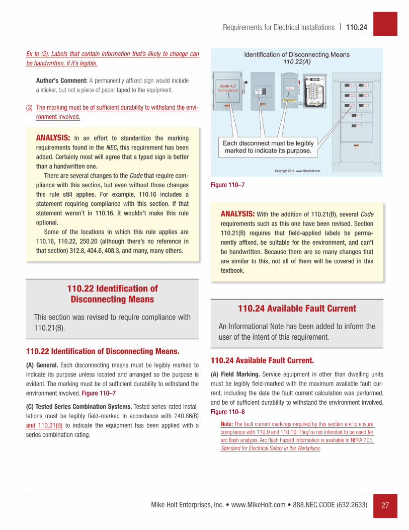
Author’s Comment: Electrical raceways and cables not asso-ciated with the dedicated space can be within the dedicated space. These aren’t considered “equipment foreign to the elec-trical installation.” Figure 110–27
(b) Foreign Systems. Foreign systems can be located above the ded-icated space if protection is installed to prevent damage to the elec-trical equipment from condensation, leaks, or breaks in the foreign systems, which can be as simple as a drip-pan. Figure 110–28
(c) Sprinkler Protection. Sprinkler protection piping isn’t permitted in the dedicated space, but the NEC doesn’t prohibit sprinklers from spraying water on electrical equipment.
(D) Illumination. Service equipment, switchboards, and panelboards, as well as motor control centers located indoors must have illumina-tion located indoors and must not be controlled by automatic means only. Figure 110–24
Author’s Comment: The Code doesn’t provide the minimum foot-candles required to provide proper illumination. Proper illu-mination of electrical equipment rooms is essential for the safety of those qualified to work on such equipment.
(E) Dedicated Equipment Space. Switchboards, panelboards, and motor control centers must have dedicated equipment space as follows:
(1) Indoors.
(a) Dedicated Electrical Space. The footprint space (width and depth of the equipment) extending from the fl oor to a height of 6 ft above the equipment or to the structural ceiling, whichever is lower, must be dedicated for the electrical installation, Figure 110–25. No piping, ducts, or other equipment foreign to the electrical installation can be installed in this dedicated footprint space. Figure 110–26
Ex: Suspended ceilings with removable panels can be within the dedi-cated footprint space [110.26(E)(1)(d)].
Figure 110–26
Figure 110–24
Figure 110–25
Mike Holt’s Illustrated Guide to Changes to the NEC 201434
110.26 | Requirements for Electrical Installations
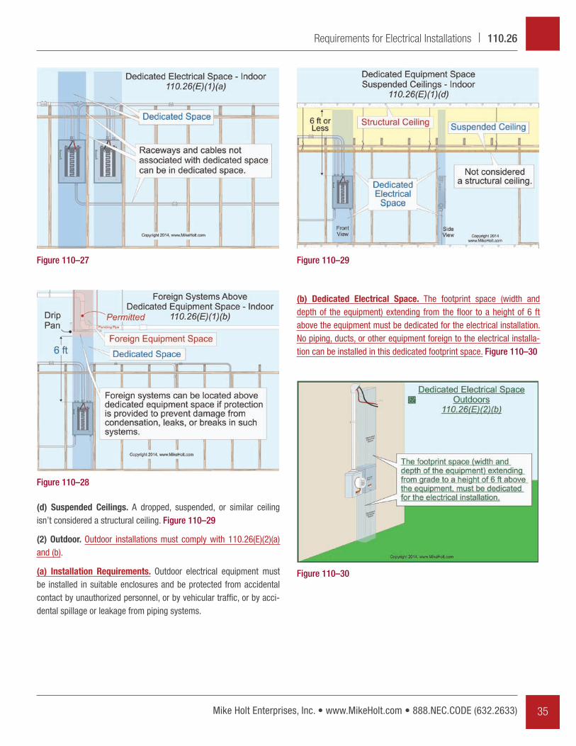
(b) Dedicated Electrical Space. The footprint space (width and depth of the equipment) extending from the fl oor to a height of 6 ft above the equipment must be dedicated for the electrical installation. No piping, ducts, or other equipment foreign to the electrical installa-tion can be installed in this dedicated footprint space. Figure 110–30
(d) Suspended Ceilings. A dropped, suspended, or similar ceiling isn’t considered a structural ceiling. Figure 110–29
(2) Outdoor. Outdoor installations must comply with 110.26(E)(2)(a) and (b).
(a) Installation Requirements. Outdoor electrical equipment must be installed in suitable enclosures and be protected from accidental contact by unauthorized personnel, or by vehicular traffi c, or by acci-dental spillage or leakage from piping systems.
Figure 110–27
Figure 110–28
Figure 110–29
Figure 110–30
35Mike Holt Enterprises, Inc. • www.MikeHolt.com • 888.NEC.CODE (632.2633)
Requirements for Electrical Installations | 110.26

110.27 Guarding
The height requirements for the guarding of equip-ment have been clarifi ed and increased.
110.27 Guarding.
(A) Guarding Live Parts. Live parts of electrical equipment operating at 50V or more must be guarded against accidental contact. This can be done by:
(1) Locating them in a separate room, vault, or enclosure.
(2) Guarding with a partition or screen.
(3) Locating them on a balcony or platform.
(4) Elevating them above the fl oor or working surface, in accordance with the following:
(a) 8 ft for 50V through 300V.
(b) 8½ ft for 301V through 600V.
ANALYSIS: The requirements for guarding live parts have been revised in order to correlate with the National Electrical Safety Code (NESC). It’s typically used by utility companies as the document that regulates their installa-tions. In many instances there’s no need to correlate the NEC and the NESC, since they’re intended to have differ-ent rules. In this case, however, it was determined that the NESC has the better rule for elevation requirements, so it’s been copied and pasted here.
(F) Locked Electrical Equipment Rooms or Enclosures. Electrical equipment rooms and enclosures housing electrical equipment can be controlled by locks because they’re still considered to be accessi-ble to qualifi ed persons who require access. Figure 110–31
Author’s Comment: See the definition of “Accessible as it applies to equipment” in Article 100.
ANALYSIS: New to this edition of the NEC is a require-ment for outdoor equipment to have dedicated space above and below it, similar to the requirements for indoor instal-lations. The intent of the dedicated space rule for indoor equipment is to allow the installer enough space to install raceways and cables. This is just as important outdoors as it is indoors.
Figure 110–31
Mike Holt’s Illustrated Guide to Changes to the NEC 201436
110.27 | Requirements for Electrical Installations