Embed Size (px)
Citation preview

Arrow Shark XP254M II Owner Manual
Specification Capacity: 25.4cc
Bore & Stoke: 34mmx28mm
Modified Walbro WKY33 Carburetor
Max Power: 6.3 HP
Max Torque: 2.58 ftlbs
RPM Range: 380018500+RPM (Under Load)
Weight: 1960 Gram (with Arrow Shark Engine Mount)
1660 Gram (Without an Engine Mount)
Engine Mount (Optional)

XP254M II SetUp and Operating Instruction
#1: Starting the engine The XP254M II comes with a ProMod Walbro WYK33 racing carburetor which does not have a
primer bulb, choke or return gas line like the more common WT644 or WT711 carbs as usually fitted to stock Zenoah or CY engines. The WYK33 carb gives ultimate performance but does require a different starting procedure. Having prepared your engine and boat in the usual way (with full regard to all safety aspects). and having filled your fuel tank, follow these steps for easy starting: l Manually choke the engine by blocking the carb intake venture with your thumb or finger and slowly
pulling the starter rope a few times. l Check that fuel is being sucked along the gas line up to the carb; continue slowly pulling the starter
rope until the gas line is clear or bubbles and you can feel fuel wetting your thumb or finger. l Remove your thumb or finger from the carb and open the throttle a bit less than half way. l Slowly pull the starter rope one more time to check the engine is not flooded (see blow). l Smartly pull the starter rope in the usual way until the engine starts. l Bring the throttle back to a steady idleDO NOT allow the engine to overrev as this can cause
damage. If too much fuel is sucked into the engine as you choke it, the engine will be flooded and will not start. It may be harder to pull over on the starter as the excess fuel increases compression. If this happens: 1. Remove the spark plug and carefully wipe dry the electrodes with a clean rag before setting the
plug safely aside. 2. Hold the clean rag just above the plug hole and pull the starter rope smartly a few times to clear
the excess fuel. 3. Reinstall the spark plug and open the throttle a big less than half way. 4. Slowly pull the starter rope in the usual way until the engine starts. 5. Bring the throttle back to a steady idel.
For “hot restarts” you may not need to chock the engine. Check that the fuel line is full of gas with any bubbles and smartly pull the starter rope. If the engine doesn’t start after a few pulls, then manually chock the engine as above and slowly pull the starter rope until you can feel fuel wetting your thumb or finger before removing it from the carb venture. Slowly pull the starter one more time to check the engine is clear, and then pull smartly until the engine starts.

#2: Breakin engine To ensure long life and good performance from your engine, you MUST break it in properly. Using
87 or 90 Octane regular pump gas; mix with 100% Syntheses Quality oil at a ratio of 16:1 (6% oil). Operate your engine at about 1/2 to 3/4 maximum throttle opening during the breakin process. Do Not run at full throttle while breaking in your engine. Patience is very important here: the boat will run slowly during the breakin process and the engine’s output power will increase gradually over the first 34 tankfulls of fuel. Once the engine is broken in, the power will increase substantially.
#3: Carb Settings The XP254M comes with a Walbro WYK33 ProMod carburetor as mentioned above, and the carb
has been preset at the factory. However, it may require adjustment to compensate for different ambient conditions such as varying temperature, humidity, altitude, etc. The carb has three adjustment the low and high speed needle and the idle screw.
#1: LowSpeed Needle: The low speed needle of the WYK33 carburetor is hiding in the center of the carburetor barrel. You need to Use a small precision flat blade screwdriver to adjust it. When adjusting the LowSpeed Needle, you need to apply Loctite#222 on the needle thread in order to hold the needle in position during the operation. The LowSpeed Needle is set at 7 turns out from the start point.
#2: HighSpeed Needle: The HighSpeed Needle is set approximately 2 plus 1/2 from start point.
#3: Idle Screw: Set at lowest RPM where the engine idles reliable without stopping. Screwing the idle screw in will make your engine rev faster.

You may also need to adjust the settings for your throttle servo. This needs to be set so that the engine idles smoothly when your radio transmitter trigger (or other throttle control if not a wheel/trigger transmitter) is at is neutral position. You may need to adjust the throttle pushrod linkage and/or use your throttle trim to adjust the idle speed up or down to get a reliable idle. When your trigger is pulled fully open for high speed, the servo movement should have the engine’s throttle barrel fully open. You may need to adjust your pushrod linkage and /or the servo’s travel so that the throttle barrel is fully open with the trigger pulled all the way, but the servo should not stall by trying to force the barrel further than it will go. Similarly, the servo should be adjusted so that it fully closes the barrel and stops the engine when you push the trigger (or apply the “brake” in RC car terms).
#4: Carburetor adjusting tip: Note: When adjusting the needles from their standard settings, move them only 1/8 of a turn a time. Check the results then adjust further as needed. Never attempt to tune the highspeed needle by running the engine at full throttle out of the water! This is very dangerous and damages the engine.
A: LowSpeed Needle If the engine is easy to start, and idles a little rough (rich), and responds well when you open the
throttle with a brief show of smoke through the exhaust, then the low speed needle is close to being correct. If the engine tends to hesitate or bog down when you open the throttle quickly (especially when the engine is cold), or if the idle speed is too high even with the throttle barrel nearly closed, the low speed needle is probably to lean and you need to screw it out (1/8 of a turn at a time). If the engine floods easily and is hard to start, the low speed needle is probably set to rich and you need to screw it in slightly.
B: HighSpeed Needle: When this needle is correctly set, the engine will run clearly, accelerate well from half throttle
without hesitation, and will not lose RPMs during turns. It is tempting to lean the high speed needle to optimize the mixture for peak power and onwater RPM, but going to lean can be risky as the engine will suffer from overheating and reduced lubrication. This can lead to damage or shorter life for your engine. If the engine stops or loses RPMs when your boat is running on the water, the high speed needle is probably set too lean and you need to screw it out slightly. If the engine is not running cleanly and seems to hesitate or not reach peak RPMs, then the high speed needle is probably set too rich and you need to screw it in slightly. Running with a slightly rich mixture may cause a small drop in top speed, but it will allow your engine to run cool and with good lubrication for reliability and long life.

Part List
Number Description Number Description #1 Billet Cylinder & Sleeve #15 Ignition Coil #2 Four Bearing Billet Crankcase #16 Exhaust Adaptor #3 ProMod Walbro WYK33 Carburetor #17 Short Head Iridium Spark Plug #4 Billet Head Bottom & ORing #18 Flange Base #5 Billet Water Jacket Header #19 Copper Cylinder Base Gasket #6 Crankshaft & Piston Assembly #20 Crankcase Gasket #7 Flywheel & Key #21 Steel Cylinder Blots #8 Billet Ignition Coil Plate #22 M5x40 Bolts & Spacers #9 Rotated Carburetor Block & Gaskets #23 M4x20 Water Jacket Bolts #10 Heavy Duty Pull Starter #24 M4x16 Flange Bolts #11 Pull Starter Adaptor #25 #632x16 Head Bottom Bolts #12 M5x40 Bolts #26 Water Jacket Center Oring #13 Source Coil #27 Water Jacket Edge Oring #14 CNC Adjustable Coils Mount

XP254M II Reassembly Guide
Tools Required
#1 Torque Wrench #7 7mm Wrench #2 272 Loctite #8 #632 Socket Wrench #3 Digital Caliper #9 3mm Socket Wrench #4 Custom Tool for Flywheel Adaptor #10 4mm Socket Wrench #5 High Temperature Sealant #11 6mm Socket Wrench #6 Piston Stopper #12 5mm Socket Wrench

* Prepare the crankshaft & piston assembly for next installation. * Push the back piece of the crankcase onto the back part of the crankshaft, being careful to correctly align the two small holes on the back part of the crankcase with the two pins on the front crankcase.
* Apply Loctite to the bolts, and then install the billet coil mounting plate onto the back piece of the crankcase.
* Prepare the cylinder, head bottom and bolts for next installation.
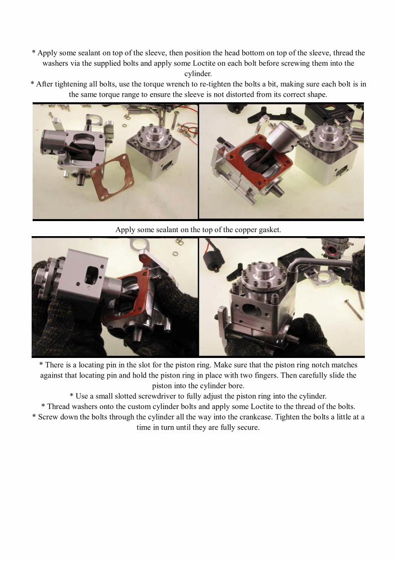
* Apply some sealant on top of the sleeve, then position the head bottom on top of the sleeve, thread the washers via the supplied bolts and apply some Loctite on each bolt before screwing them into the
cylinder. * After tightening all bolts, use the torque wrench to retighten the bolts a bit, making sure each bolt is in
the same torque range to ensure the sleeve is not distorted from its correct shape.
Apply some sealant on the top of the copper gasket.
* There is a locating pin in the slot for the piston ring. Make sure that the piston ring notch matches against that locating pin and hold the piston ring in place with two fingers. Then carefully slide the
piston into the cylinder bore. * Use a small slotted screwdriver to fully adjust the piston ring into the cylinder.
* Thread washers onto the custom cylinder bolts and apply some Loctite to the thread of the bolts. * Screw down the bolts through the cylinder all the way into the crankcase. Tighten the bolts a little at a
time in turn until they are fully secure.

* Install the water seal ring into the edge of the cooling header, and position the header onto the cylinder. * Tighten the cooling header onto the cylinder with the bolts supplied.
* Prepare the coils mount with both source coil and ignition coil, apply some loctite on all bolts, and install them together as shown in above picture.
* Install the coils mount assembly onto the engine back plate, and prepare the flywheel and pull starter adaptor for next installation.

* First, install the piston stopper into the spark plug hole on the cylinder. * Position the flywheel key into the crankshaft slot.
* Slide the flywheel onto the crankshaft, and apply some Loctite on the thread of the crankshaft. * Screw the pull starter adaptor (Part#11) onto the crankshaft thread, and then tighten it with the special
tool mentioned earlier.
Squish Band Clearance Check The squish band thickness is the distance between the piston and the cylinder head when the piston is at the top of the cylinder bore. If the squish band clearance is set to an optimal amount, then the fuel is burned efficiently. If the squish distance is too great, then the fuel in the squish band is not burned and the engine runs very “dirty” so that it is inefficient and does not produce optimal power. Setting the proper squish clearance is very critical to the correct performance of an engine. We set our billet
XP254M II’s squish clearance around 0.40mm depending on the thickness of the gasket and sealant that is applied. Please follow the below steps to check the squish clearance before you start the engine.
* Prepare a piece of soft solder (0.9mm diameter), and a digital caliper. * Bend about 3mm at the end of the solder, and then insert it into the cylinder via the spark plug hole. Position the solder so that it will get squished between the piston and the squish band as you gently turn the flywheel. Carefully remove the solder from the cylinder and use a digital caliper to measure the
thickness of the solder where it was compressed by the piston (see above right photo). * The caliper should read at around 0.4mm.
* If the measurement is outside these dimensions, change the thickness of the gasket, or use slightly more or less sealant, until the measurement is correct.

* Install the rotated carburetor block with supplied gasket.
* Insert the supplied bolts via the venturi and carburetor, and then tighten them to secure the carb to the block.
* Install the air pressure tube between the nipple that has been preinstalled on the carburetor and the nipple on the crankcase.
* Bolt the inner piece of the exhaust flange with the exhaust adaptor that comes with the engine (Part#16) to the exhaust port with the supplied bolts. The XP254M II doesn’t come with engine mount, it needs to order from Arrow Shark separately or use any type of Zenoah mount from your own.

Performance tip: Tuned pipes boost engine power by using the pressure waves generated by exhaust gases to literally pull more fuel into the cylinder. However, to achieve this, it is critical to have the right length for the exhaust gases as they travel from the exhaust flange to the “belly” of the tuned pipe (that’s where the pipe is at its widest diameter). For our billet XP254M II, this distance is between 310 and 330mm which needs to be measured along the centre line of the exhaust including the header pipe, as shown in the diagram. Having either a longer or shorter length will reduce the engine’s performance.
We recommend customers to use our latest version 2” band steel tuned pipe series for our XP254M II as these pipes were designed for the engine.
Engine Care and Maintenance A: Keep your engine clean, Spray it with WD40 or a similar product after each outing and wipe it clean to prevent corrosion and to avoid any buildup lf dirt that might enter the engine and cause wear or overheating. B: Do not allow your engine to run with too lean a fuel mixture – this causes overheating and rapid wear or even damage. C: Do not run your engine with a damaged or unbalanced prop; this causes vibration and can damage your engine or cause other problems including with your radio equipment. D: Do not overheat the engine. Frequently check that cooling water is flowing from the outlets in your hull and never allow your engine to run for more than a minute or so at idle without water flowing through the cylinder jacket and exhaust cooling fittings. E: Avoid using old fuel in the engine. Always run all of the fuel out of the engine. After running for the day, use afterrun oil and work it into the engine by pulling the starter 23 times. If you run your boat in salt water, flush the cooling system afterwards with fresh water for several minutes. Drain all water from the cooling system. F: Store your engine somewhere that is not subject to extreme temperature change. G: If you are not planning to run your engine for more than a month, drain the fuel tank and remove any fuel from inside the carburetor. Do these by running the engine at idle until it stops by running out of fuel. Keeping gasoline inside the carburetor over an extended period of time will damage the diaphragm valve and clog passages inside the carburetor.
www.arrowshark.com