Embed Size (px)
Citation preview

Army radio communication in the Great WarKeith R Thrower, OBE
IntroductionPrior to the outbreak of WW1 in August 1914 many of the techniques to be used in later years for radiocommunications had already been invented, although most were still at an early stage of practical application.Radio transmitters at that time were predominantly using spark discharge from a high voltage induction coil,which created a series of damped oscillations in an associated tuned circuit at the rate of the spark discharge. Thetransmitted signal was noisy and rich in harmonics and spread widely over the radio spectrum.
The ideal transmission was a continuous wave (CW) and there were three methods for producing this:
1. From an HF alternator, the practical design of which was made by the US General Electric engineerErnst Alexanderson, initially based on a specification by Reginald Fessenden. These alternators wereprimarily intended for high-power, long-wave transmission and not suitable for use on the battlefield.
2. Arc generator, the practical form of which was invented by Valdemar Poulsen in 1902. Again thetransmitters were high power and not suitable for battlefield use.
3. Valve oscillator, which was invented by the German engineer, Alexander Meissner, and patented inApril 1913.
Several important circuits using valves had been produced by 1914. These include: (a) the heterodyne,an oscillator circuit used to mix with an incoming continuous wave signal and beat it down to an audible note;(b) the detector, to extract the audio signal from the high frequency carrier; (c) the amplifier, both for theincoming high frequency signal and the detected audio or the beat signal from the heterodyne receiver; (d)regenerative feedback from the output of the detector or RF amplifier to its input, which had the effect ofsharpening the tuning and increasing the amplification.
Valves at this time were still at a fairly primitive state of development. Those available were:
1. The diode detector patented by John Ambrose Fleming in 1904 (Figure 1, left). It was little used andsoon superseded by the crystal detector.
2. The Audion, invented by Lee de Forest at the end of 1906 (Figure 1, right). This was a ‘soft’ amplifyingtriode and quite erratic in its operation. Over the period 1913 to 1915 the Audion design was radicallyimproved by the two US companies, General Electric and Western Electric, both companies producingvalves with a high vacuum. It took a couple more years before these could be manufactured in highvolume.
3. Some ‘soft’ triode valves designed by Henry Round of the Marconi Company in 1913. There were twodistinct types, each with some variants: The T, which was a transmitter valve and the C, a receiver valve(Figure 2). These valves were hand-built and very difficult to manufacture. They had an extension at thetop of the glass envelope; this was filled with a wad of asbestos which required heating from time-to-time to release occluded gas to improve their sensitivity. Because of manufacturing problems thesevalves could not be produced in large quantities and they required special care in their use. They werenot suitable for use under battlefield conditions. (Note: the valves in Figs.1 & 2 are not to scale.)
Fig. 1 (left) Commercial version of Fleming diode; (right) BT-H version of the de Forest Audion triode, a ‘soft’ valve erratic in operation.
Fig. 2: Marconi-Round C and T valves of 1913.These were both ‘soft’ valves. The C was a receivervalve for use as a detector or RF amplifier.The T was a transmitter valve.
1

Several of the circuits developed prior to 1914 were built into an early Marconi radio, the ShortDistance Wireless Telephone Transmitter and Receiver (Figure 3). This used the two Marconi valves shown inFigure 1. In the transmitting portion of the set the T (actually a T.N.) was used as an oscillator, coupled directlyto the aerial tuning circuit, and the C was used as an RF amplifier with regenerative feedback. The output fromthis valve was transformer-coupled to a carborundum crystal detector in series with a pair of headphones. Acarbon microphone was used to modulate the transmitter.
Fig 3: Marconi Short Distance Wireless Telephone Transmitter and Receiver.This set used a C valve in the receiver, connected as an RF amplifier with regenerative feedback to increase its gain and provide improved selectivity. Detection was by a carborundum crystal.For transmission there was a single T.N. valve (seen mounted in the frame) and this was connected as an oscillator.It is believed that Marconi used this set for CW voice trials in 1914.
It might have been possible to adapt this radio for use in benign environments in the early years of thewar but this was not to be and it was necessary to await improved, more robust valves that could be readilymanufactured in large quantities. Consequently, all the early radio transmitters used by the army in WW1 werespark sets and these continued to be used during the whole of the war. All the early radio receivers used crystaldetectors, the two most used being the carborundum and the Perikon detectors, described later in this paper.
Early army radiosAt the start of the war the only radios available were a few 500-watt and 1500-watt spark transmitters and theircrystal detector receivers (Figures 4 & 5). The 500-watt station could be carried on the back of four horses butthe 1500-watt station, Type F2, required two carriages of the limber and wagon type. These were the power cart,which housed the spark generating set, powered by a petrol-driven alternator, and the operating cart, each beingdrawn by a team of four horses [1]. The 1.5kW station required eight men who took twenty minutes to erect thestation for action. The aerial was a wire of length 525ft long mounted horizontally on two 70ft tubular steelmasts.
Fig 4: Marconi 1.5 kW spark generator of approx. 1911design. Note the rotating spark gap seen at the front.
Fig 5: Marconi 1.5 kW spark Pack Set showing the operating cart with the crystal set receiver.
The principal method of communication by the British army, up to late 1917, was by cable for speechand Morse transmission. Initially, a single cable was laid above ground and the earth used as the return.However, the cable was vulnerable to damage by enemy fire and, later, by the passage of tanks across thebattlefield. In an attempt to rectify this insulated cable was buried at ever increasing depth but this didn’t avoidthe cable being severed. Very often communication was not possible, particularly when troops were movingrapidly forward or in retreat. During the course of the war tens of thousand miles of cable was laid and, at times,
2

there was an acute shortage of replacement cable. An excellent account of the communications problems duringthe war can be found in a book by Mike Bullock and Laurence Lyons [2].
A further problem with cable was that the Germans were often able to listen in by picking up earthcurrents or tapping into the cable. This was not realized at first, but when, discovered, it was necessary to limitthe number and content of the message and, where possible, to use codes or encryption. The best solution,however, was to use the Fullerphone, an invention of Capt. A C Fuller [3], which made the signal immune fromeavesdropping. The use of this required special training for the operators and was not universally available. Inspite of its name the Fullerphone was only used for Morse transmissions.
Other non-wireless means of sending messages that were used with mixed success during the war wasby runners, dispatch riders, pigeons, lamps and flags. However, as will be outlined in this paper, wireless becameincreasingly important as the war progressed, particularly in its last year.
Up until the end of March 1918 the Royal Flying Corp (RFC) was part of the army and experimentalwork on aircraft radio communication was carried out at Brooklands. It was here that Major Charles Prince,previously a Marconi engineer, carried out pioneering work on radio development and in this he was assisted byMajor Robert Orme, Capt. H J Round an Lt. J M Furnival. The development group at Brooklands was seriouslyunderfunded but, in spite of this, Prince worked on the development of CW voice transmission. This culminatedin mid-1916 with the successful demonstration of ground-to-air speech communication. However, it was to be afurther two years before suitable equipment for speech communication was to be incorporated in aircraft.Consequently all the early radios were spark transmitters fitted in the aeroplanes and crystal receivers used onthe ground. (Note: Work transferred to Biggin Hill in late spring of 1917.)
No 1 Aircraft SparkAmongst the earliest radios to be used in aeroplanes was the 30-watt, No 1 Aircraft Spark (Figure 6), poweredfrom a 6-volt accumulator. The set was designed in 1914 and fitted to approximately 600 aircraft during 1915[4, 5]. It was used for spotting enemy artillery and reporting back to ground by Morse code. The transmittercovered the band 100–260m (1.15–3MHz). In operation it required a trailing wire aerial of length ranging from100 to 200ft (30.5–61m) with a lead weight at its end. Variants of this set were used throughout the warincluding the 52M, a 40-watt set covering the band 150–410m (732 kHz–2MHz), powered from an 8-voltaccumulator. There was also a 150-watt set, the 52A, covering the same frequency band as the 52M but poweredby a propeller-driven alternator. Including all the variants, nearly 4000 of these sets were manufactured duringthe war.
Fig 6: No. 1 Aircraft Transmitter Spark. 30-watt input.Note the spark gap on the top right inside the cabinet
with the adjustment for the gap at the front.
Fig 7: W/T Trench Set 50 Watt D.C. (Also known as the BF set)
The spark gap is clearly seen at the bottom.
Unlike with the RFC there was a general lack of enthusiasm in the army for using radios, particularlyduring the first two years of the war. There were several reasons for this.
1. The equipment available at the time was very bulky and required several Signal Service operators toman them.
2. The radios required accumulators, which required frequent re-charging.3. There was the genuine fear that the enemy would be able to intercept the messages.
3

This situation was to change later in the war when radio had proved to be the only reliable way tocommunicate when troops were on the move, making it even more imperative for Divisions to keep in touch.Also when tanks came into service in early 1916 the only way that the crew could communicate was by wireless.
4

The BF Trench SetOne of the earliest radios to be used in the trenches was the W/T Trench Set 50 watt D.C, also known as the BFSet (Figure 7) which was used for communication from Brigade to Division. There is some confusion aboutwhen this set came into service. According to Capt. Schonland ‘They went into “action” in the 1st Battle of theSomme, July 1st 1916’ [6, 7]. A more recent source says it came into service in 1915 and went into action in theBattle of Loos in September 1915 [8]. The transmitting portion of set was based on the design of the No 1Aircraft Spark set. However, in addition, the set had a built-in receiver using a carborundum crystal as thedetector. It was powered from a 10-volt accumulator and also required dry-cell batteries for biasing thecarborundum crystal and an internal test buzzer.
The transmitter could operate on one of three wavelengths: 350, 450 and 550m (857 kHz, 667 kHz and545 kHz). The receiver covered the wider band of 300–600m (500 kHz–1MHz).
A vulnerable feature of the radios was the need to have an aerial of length ranging from 60–80yd (55–73m) mounted on masts, making them easy target for enemy gunfire. The aerials could, however, be run close tothe ground but this reduced it range of operation from 4000yd to 1200yd (3.7km to 1.1km).
As mentioned in the introduction, spark transmitters spread their energy over a wide band and their userequired careful planning to avoid interference from neighbouring transmitters. This could be done by usingwidely spaced frequencies for closely located transmitters and ensuring that the same frequencies were used atwidely separated locations. As is shown later in this paper the problem was overcome when CW valvetransmitters were introduced.
The BF set was used extensively during the second half of the war and approximately 1200 weremanufactured by the W.D. Factory and the Marconi’s Wireless Telegraph Company.
Crystal DetectorsBefore going further mention should be made of the two types of crystal detector used in army radios during thewar. The most common of these was the carborundum crystal composed of silica and carbon, invented byDunwoody in 1906. This was a very robust device but had the disadvantage that for maximum sensitivity itrequired a bias of typically 1½ volts to 3½ volts, with adjustment by a potentiometer in conjunction with a dry-cell battery. The other was the Perikon, a combination of the two crystals, zincite and chalcopyrites, which wasinvented by Pickard in 1909. This had the advantage of being more sensitive than the carborundum crystal anddidn’t require a bias voltage. It’s disadvantage, however, was that it was more delicate in operation and requiredconstant adjustment, given even a slight knock. Several of the army radios had both types of crystal fitted with achangeover switch to select one or the other. The radios also frequently had a test buzzer included which couldproduce an audio modulated signal via the tuned circuit of the receiver and this was used to adjust the crystalsfor optimum sensitivity and test the headphones.
Fig 8: W/T trench Set 130-watt Wilson. Transmitter only; used with Tuner Short Wave Mk. III.
Fig 9: Tuner Short Wave Mk. III*. This receiver has both a carborundum and a Perikon detector.
130-watt Wilson Trench Set & Short Wave Tuner Mk. IIIThe W/T Trench Set 130 Watt Wilson Transmitter, to give it its full name was used primarily for Division toCorps communication and Corps Directing Station (Figure 8). This set came into service about the same time as
5
the BF Trench Set [9]. But, unlike the BF set, it had a fixed spark gap with a motor-driven, high-speedinterrupter rather than the slower magnetic interrupter. The result was a greater number of sparks were producedper second giving a musical note at the headphones, thereby making the Morse signal more easy to hear throughinterference. The transmitter had the same three fixed frequencies as the BF set and the higher power meant thatthe range was up to 9000yd (approx. 8.3km), with an aerial supported on 30ft masts. The power was supplied bya 26-volt or 28-volt accumulator.
Tuner Short Wave Mk. III*The original Mk. III version of this tuner was introduced in 1916 and the Mk. III* in 1918 (Figure 9). It coveredthe band 100–700m (429 kHz–3MHz). Its prime purpose was to receive Morse messages from aircraft flyingover the trenches but it was also used with the 130-watt Wilson Set. Either a Perikon or carborundum crystal wasused for the detector. The carborundum crystal required two 3-volt dry-cell batteries and the usual potentiometeradjusted for optimum sensitivity. There was also a buzzer for calibrating and testing the tuner. The aerial was125ft long laid close to the ground as a single inverted L According to Meulstee 766 transmitters and 6595receivers were produced.
There was also a Short Wave Tuner Mk. IV which came into service in 1918. This covered the band 90–320m (938 kHz–3.33MHz). It had a Perikon crystal and a 4½-volt battery for the test buzzer. Less than 200of these sets were produced.
Fig. 10a & 10b: French TM and Osram F valve.The TM was a general-purpose valve used mainly as a detector or an AF amplifier. The F was a low-power transmitting valve similar in construction to the TM.
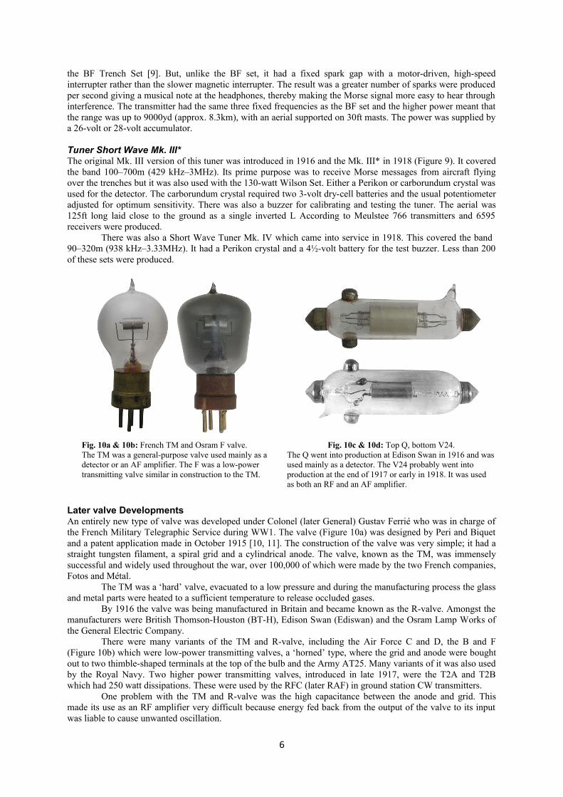
Fig. 10c & 10d: Top Q, bottom V24.The Q went into production at Edison Swan in 1916 and wasused mainly as a detector. The V24 probably went into production at the end of 1917 or early in 1918. It was used as both an RF and an AF amplifier.
Later valve DevelopmentsAn entirely new type of valve was developed under Colonel (later General) Gustav Ferrié who was in charge ofthe French Military Telegraphic Service during WW1. The valve (Figure 10a) was designed by Peri and Biquetand a patent application made in October 1915 [10, 11]. The construction of the valve was very simple; it had astraight tungsten filament, a spiral grid and a cylindrical anode. The valve, known as the TM, was immenselysuccessful and widely used throughout the war, over 100,000 of which were made by the two French companies,Fotos and Métal.
The TM was a ‘hard’ valve, evacuated to a low pressure and during the manufacturing process the glassand metal parts were heated to a sufficient temperature to release occluded gases.
By 1916 the valve was being manufactured in Britain and became known as the R-valve. Amongst themanufacturers were British Thomson-Houston (BT-H), Edison Swan (Ediswan) and the Osram Lamp Works ofthe General Electric Company.
There were many variants of the TM and R-valve, including the Air Force C and D, the B and F(Figure 10b) which were low-power transmitting valves, a ‘horned’ type, where the grid and anode were boughtout to two thimble-shaped terminals at the top of the bulb and the Army AT25. Many variants of it was also usedby the Royal Navy. Two higher power transmitting valves, introduced in late 1917, were the T2A and T2Bwhich had 250 watt dissipations. These were used by the RFC (later RAF) in ground station CW transmitters.
One problem with the TM and R-valve was the high capacitance between the anode and grid. Thismade its use as an RF amplifier very difficult because energy fed back from the output of the valve to its inputwas liable to cause unwanted oscillation.
6

In an attempt to overcome this Round of the Marconi Company developed the type Q which featuredsmall size and low capacitance [10c]. The valve had a straight tungsten filament terminated by the two pointedmetal caps at each bend of the bulb. Both the anode and grid connections were taken to two further caps near oneend of the tubular glass bulb. The Q was primarily intended as a detector but it was also used as both an RF andAF amplifier. It overall length was 73mm and the bulb diameter 16mm.
Later in the war Round designed a new valve, better suited as an RF or AF amplifier. This was the typeV24 (Figure 10d). There is some uncertainty over when this valve was first used but the best guess is late 1917or early 1918. It had similar dimensions to the type Q. (Commercial production was not until October 1919.)
A soft triode valve was designed by GW White at the Cavendish laboratories in 1916, but this was littleused. One application, described later, was in an aircraft tuner.
Later army radiosValve radios first made their appearance in 1916. One of the earliest was the Tuner Aircraft Valve Mk. I [12].This radio is believed to have covered the band 300–800m (375 kHz–1MHz) and used a single Q valve poweredby a 6-volt battery for the filament and a 100-volt battery for the HT. It was not made in significant numbers.
W/T Set Forward Spark 20 watt “B”This set came into service in 1917 and was also known as ‘The Loop Set’ and was used for forwardcommunication [13]. There were both Rear Stations and Front Stations sets (Figure 11). There were two versionsof each, having fixed wavelengths of 65m and 80m (5MHz and 3.75MHz). There were also separate receiversfor the Rear and Forward Stations (Figure 12). These receivers had two valves which could either be the FrenchTM or the British R.
For both the rear and forward versions the transmitter had a fixed spark gap powered directly from aninduction coil operating in a similar way to the BF Trench Set. The power for the stations was supplied by a6-volt accumulator and a 32-volt HT battery.
The radios were made in quite large quantities: approximately 4000 of the transmitters and a similarnumber of the receivers.
Fig. 11: W/T Forward Spark 20-watt “B” transmitter. Fig. 12: W/T Forward Spark 20-watt “B” receiver.
W/T Trench Set Mk. I 30-wattThe first CW sets for field use were made in 1916 and used a single valve for both the transmitter and receivercircuits. (Note: it is not clear whether this was the Mk. I version of the set.)
The set, shown in Figure 13, came into service in 1917 and was used for forward communication byICW. It incorporated a high-speed interrupter to modulate the transmission. (Because of confusion with thevarious Marks this set may have been the Mk I** version but this is not clear from the photograph.) A singleTM or R valve was used both for the transmitter and the receiver.
There were three versions of the set: the Mk I, which covered the band 500–1400m (214–600 kHz), andthe Mk I* & Mk. I** which covered the band 700–1400m (214–429 kHz). It had a range of 5 miles (8km).
The Mk I** version had provision of an alternative high-tension supply which took the form of a ‘tunedvibratory transformer’ (T.V.T) unit. This was later used with other sets.
7

The aerial was a 150ft wire on 15ft masts and there was an earth mat. The set was powered from a 6-volt accumulator and a 400-volt HT battery. The total production was about 250.
Fig 13: W/T Trench Set Mk. I.Combined transmitter & receiver.
Fig 14: W/T Receiver Short Wave Mk. III**.
W/T Receiver Short Wave Mk. III**This is a general-purpose receiver covering the band 110–700m (428 kHz–2.73MHz). The original version was acrystal receiver having both a carborundum and a Perikon crystal. The Mk. III** version of 1917, shown inFigure 14, had the addition of a TM or R valve with regenerative feedback. The valve is missing from thephotograph but its socket can be seen near the top right hand corner.
The carborundum detector required two 3-volt batteries and there were separate LT and HT batteries forthe valve.
The aerial had a length of 100–125ft (30.5–38m) and was supported on 15ft masts and there was theusual earth mat.
Total production was only 100.
W/T Set Trench CW Mk. III*This was also one of the first continuous wave (CW) sets to be produced, and comprised a transmitter and aheterodyne receiver in separate boxes (Figure 15 & 16) [14]. It came into service in 1917 and was used forforward area telegraphy. At the time this type of transmission was known as ‘tonic train’ or interrupted CW(ICW) where the waveform was produced by a valve oscillator.
The transmitter was rated at 30-watts and covered the band 450–1450m (207–667 kHz). Its typicalrange was 4000yd (approx. 3.7km). The earlier Mk. III version had a single valve, a type B or the AT25.However, the Mk. III* shown in Figure 15 had two of these valves.
8

Fig 15: W/T Trench Set Mk III* transmitter. Fig 16: W/T Trench Set Mk III* receiver.
The receiver had two R valves. The first of these was operated as a self-oscillating mixer, where theoscillator frequency was adjusted close to that of the incoming Morse signal. As a result of this slight differencein frequency low frequency ‘beats’ were produced. These were passed to the second valve which amplified themto produce an audible tone in the headphones corresponding to the dots and dashes of the Morse signal.
The aerial was a wire of length 50 to 150ft, depending on wavelength, and supported on masts. Therewas also a 14ft earth mat.
In addition to the transmitter and receiver the complete set also included a heterodyne wavemetercovering the band 400–3000m (100–750 kHz). Optional extras were a Selector Unit and Rectifier Unit. Theselector unit had tuning coils and capacitors which, when connected to the receiver, provided greater freedomfrom interference. The rectifier unit converted the alternating high-tension voltage from a vibrator to provide aDC output
Total production was a little under 3000 for both the transmitter and the receiver. Approximately 400 ofthe Selector Unit were produced and these were shared between all the stations.
Tuner Aircraft No. 9Very little is known of this tuner which was manufactured in 1916. It was a heterodyne receiver and used asingle White valve. A photo of the receiver is shown in Figure 17. The White valve can be seen sticking out ofthe top of the cabinet. The terminal at the top is connected to the anode of the valve.
It is doubtful if very many of these tuners were used because it is not mentioned in the list of wirelesssets given in Erskine-Murray’s paper (Ref. 4).
Fig. 17: Tuner Aircraft No. 9.This went into service in 1916.
Fig 18: Telephone Wireless Aircraft Mk. II,
9

complete with remote control and headphones.
Telephone Wireless Aircraft Mk. IIAir telephones were put into production by mid-1917 and fitted in aircraft later in the year.
The Telephone Aircraft Mk. II covered the narrow band of 350–450m (667–857 kHz). A photograph ofthe set can be seen in Figure 18. It had two valves, which was either the B or F, one being used for control andone the power output valve. A 6-volt accumulator was used to supply the valve’s filaments and the HT wasderived from a BT-H wind-driven generator producing 600-volts DC. It had a range of 2 miles to other aircraftand 15 miles to ground stations.
The aerial was a trailing wire of length 100–150ft with a lead weight at the end. According to Erskine-Murray: ‘In certain cases we have tried to use an aerial made up entirely within the machine, consisting of wireson the wings and inside the fabric … Fixed aerials were designed for the purpose of fighting, because it isinconvenient, naturally, to have 150 feet of wire trailing below them … it may get entangled and interfere withthe controls.’ [15]
The earlier attempts to fit radio telephones in aircraft had been hampered by the high background noisefrom the aircraft’s engine. This problem was alleviated by the design of a helmet with built-in microphone andearphones to block much of the noise.
A typical receiver for use with this transmitter was the Tuner Aircraft Mk III which had three type-Rvalves, one for the detector and two for low-frequency amplification. The receiver covered the two bands 350–450m, as used in the transmitter, and 600–800m (375 kHz–500 kHz). There was also a remote control unit.
ConclusionsIn a paper of this length it has not been possible to cover all the radios used by the British army during WW1.However, those chosen are a representative selection. There were also many amplifiers but these are not coveredin this paper.
The army was very slow to adopt wireless for communication on the battlefield and relied too much oncommunication by cable. There was a genuine fear that wireless would be intercepted by the enemy but this wasalso true with cable. The cable used was being constantly severed by shell fire and the passage of tanks acrossthe battlefield. As a back-up runners, despatch riders, pigeons, flags and lamps were used but these, too, wereonly moderately successful. This meant that important messages could often not be sent.
Apart from a few high-powered transmitters that played a minor role in the war, the first wirelesstransmitters were fitted in aircraft during 1915. These were used to communicate with crystal receivers on theground to direct artillery fire.
The first trench sets went into service towards the end of 1915. From this time onward the army cameslowly round to realizing that wireless communication was a more reliable way to communicate than by cable,particularly when troops were moving rapidly forwards or backwards.
The most significant technical breakthrough came following the development of thee TM valve in France.This, and its many derivatives, enabled reliable valve transmitters and receivers to be produced from 1916onwards. It now became possible to make CW transmitters, which were far superior to the spark sets.
By mid-1917 the army at last began to accept that radios were the best way to communicate and increasingnumbers of these came into service in the final year of the war. One is left to wonder how much shorter the warmight have been and how many lives not lost if wireless had been adopted in large numbers on the battlefieldfrom 1916 onwards when improved valves became available, making possible communication by continuouswaves.
AcknowledgementsI should like to thank Nick Kendall-Carpenter and his archive staff at the Royal Signal Museum, Blandford forthe photographs used in Figures 6, 8, 9, 11–16 & 18.
Much of radio details have been taken from Louis Meulstee’s book Wireless for the WarriorCompendium 1. Louis also kindly supplied me with the photograph of the BF set shown in Figure 7.
I must also thank John Liffen of the Science Museum for allowing me to take photographs of radioequipment in the store at Blythe House.
References1. ‘Recent developments in field station apparatus’, Wireless World, 7, March 1919, pp.656–622. Bullock, Mike & Lyons, Laurence, Missed Signals on the Western Front: McFarland & Co. Inc.; North
Carolina, 2010. ISBN: 978-0-7864-4937-8 (Available from Amazon)3. See www.wftw.nl/ful.htm (Louis Meulstee’s website)4. Erskine-Murray, Major J, ‘Wireless in the Royal Air Force’, JIEE, 59, 1921, pp.693–700.
10

5. Hogan JJ, ed., ‘Aircraft wireless sets’, Wireless World, 7, 1919/20, pp.101, 278, 410, 470, 605, 665, 7296. Schonland, Capt. BFJ, ‘W/T.R.E’ Wireless World, 7, July–November 1919, pp.174–8, 261–7, 395–7,
452–5. See also Austin, Brian, ‘Wireless in the Trenches – W/T.R.E’., Radio Bygones, 142, April/May2013, pp.12–19
7. Ref. 6, p.1768. Ref. 2, pp.46–47 9. Louis Meulstee, Wireless for the Warrior Compendium 1, The Netherlands; Emaus Drukkerij/Uitgeverij,
2009. ISBN: 978-90-808277-2-1 (Available from Wimborne Publishing Ltd, 113 Lynwood Drive,Wimborne, BH21 1UU.)
10. Peri, M & Biquet, J. French patent 492,657, appl. 23 October 1915. Also British patent 126,568, appl. 23October 1916
11. Thrower, Keith R, British Radio Valves The Vintage Years: 1904–1925, Reading, Speedwell, 1999,Chapter 4. ISBN: 0-9537166-0-0 (Now out of print)
12. Ref. 6, p.9913. Ref. 6, pp,19–2014. Ref. 6, pp.47–4815. Ref. 4, p.698
11