Embed Size (px)
Citation preview
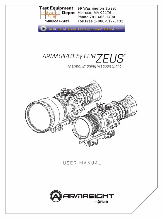
ARMASIGHT by FLIRZEUS®
Thermal Imaging Weapon Sight
U S E R M A N U A L
99 Washington Street Melrose, MA 02176 Phone 781-665-1400Toll Free 1-800-517-8431
Visit us at www.TestEquipmentDepot.com

2 ARMASIGHT by FLIRZEUS U S E R M A N U A L
© 2018 FLIR Systems, Inc. All rights reserved worldwide. No parts of this manual, in whole or in part, may be copied, photocopied, translated, or transmitted by any electronic medium or in machine-readable form without the prior written permission of FLIR Systems, Inc. Names and marks appearing on the products herein are either registered trademarks or trademarks of FLIR Outdoor & Tactical Systems and/or its subsidiaries. All other trademarks, trade names, or company names referenced herein are used for identification only and are the property of their respective owners.This product is protected by patents, design patents, patents pending, or design patents pending.If you have questions that are not covered in this manual, or need service, contact FLIR OTS customer support for additional information prior to returning a product.
This documentation is subject to change without notice.
EXPORT INFORMATION
Equipment described herein may require US Government authorization for export purposes. Diversion contrary to US law is prohibited.
©2018 FLIR Systems, Inc. Specifications are subject to change without notice

3ARMASIGHT by FLIRZEUS U S E R M A N U A L
PROPER DISPOSAL OF ELECTRICAL AND ELECTRONIC EQUIPMENT (EEE)
The European Union (EU) has enacted Waste Electrical and Electronic Equipment Directive 2002/96/EC (WEEE), which aims to prevent EEE waste from arising; to encourage reuse, recycling, and recovery of EEE waste; and to promote environmental responsibility.In accordance with these regulations, all EEE products labeled with the “crossed out wheeled bin” either on the product itself or in the product literature must not be disposed of in regular rubbish bins, mixed with regular household or other commercial waste, or by other regular municipal waste collection means. Instead, and in order to prevent possible harm to the environment or human health, all EEE products (including any cables that came with the product) should be responsibly discarded or recycled.To identify a responsible disposal method where you live, please contact your local waste collection or recycling service, your original place of purchase or product supplier, or the responsible government authority in your area.Business users should contact their supplier or refer to their purchase contract.
IMPORTANT INSTRUCTIONS AND NOTICES TO THE USER:
Modification of this device without the express authorization of FLIR Commercial Systems, Inc. may void the user’s authority under FCC rules to operate this device.Note 1: This equipment has been tested and found to comply with the limits for a Class B digital device, pursuant to Part 15 of the FCC rules. These limits are designed to provide reasonable protection against harmful interference in a residential installation.This equipment generates, uses, and can radiate radio frequency energy and, if not installed and used in accordance with the instructions, may cause harmful interference to radio communications. However, there is no guarantee that the interference will not occur in a particular installation. If this equipment does cause harmful interference to radio or television reception, which can be determined by turning the equipment off and on, the user is encouraged to try to correct the interference by one or more of the following measures:• Reorient or relocate the receiving antenna
• Increase the separation between the equipment and receiver
• Connect the equipment into an outlet on a circuit different fromthat of the receiver
• Consult the dealer or an experienced radio/television technician for help.
INDUSTRY CANADA NOTICE:
This Class B digital apparatus complies with Canadian ICES-003.
AVIS D’INDUSTRIE CANADA:
Cet appareil numérique de la classe B est conforme à la norme NMB-003 du Canada.
4 ARMASIGHT by FLIRZEUS U S E R M A N U A L
LIST OF CONTENTS
TITLE PAGE
Safety Statement 5
SECTION 1. INTRODUCTION 7
1.1 General Information 7
1.2 Warranty Information and Registration 8
SECTION 2. DESCRIPTION AND DATA 9
2.1 System Description 9
2.2 Specifications 12
2.3 Standard Components 14
2.4 Optional Equipment 16
2.5 Key Features 17
SECTION 3. OPERATING INSTRUCTIONS 18
3.1 Installation and Mounting 18
3.2 Controls and Display Indications 22
3.3 Operating Procedures 31
SECTION 4. MAINTENANCE AND TROUBLESHOOTING 37
4.1 Preventive Maintenance Checks and Services 37
4.2 Operator Troubleshooting 39
4.3 Maintenance 40
APPENDIX 42
List of Spare Parts 42

5ARMASIGHT by FLIRZEUS U S E R M A N U A L
SAFETY SUMMARY
• Read and follow all instructions
• Read all warnings
• Only use the attachments/accessories specified by the manufacturer
• All service must be provided by the manufacturer
WARNING:
Always make sure your firearm is unloaded before you place the scope on the firearm. Reconfirm that the chamber is empty if you stop the procedure then resume later. Safe handling rules should be followed at all times.
WARNING:
If a scope is mounted too far to the rear, the eyepiece can injure the shooter’s brow. Shooting at an uphill angle also increases this hazard because it shortens the distance between the brow and the rear of the scope. For this reason, Armasight scopes are engineered to provide generous eye relief. Therefore, when mounting your scope, we recommend positioning it as far forward in the mounts as possible to take full advantage of this generous eye relief. With hard-recoiling rifles, serious injury or even death can result from eyepiece impact with the shooter during the recoil process when discharging the firearm. Be certain that your installation provides sufficient eye relief for the recoil generated by your rifle before shooting the firearm. NOTE: Give special attention to this warning when shooting uphill and/or from a prone position. These shooting conditions can dramatically reduce eye relief. PLEASE maintain maximum eye relief when shooting heavy recoiling and/or magnum firearms. THE USER ASSUMES ALL RESPONSIBILITY AND LIABILITY FOR HAVING THE ARMASIGHT RIFLESCOPE PROPERLY MOUNTED TO A FIREARM AND USING THE ARMASIGHT RIFLESCOPE PROPERLY. ALWAYS CHECK THE CONDITION OF YOUR MOUNTING SYSTEM PRIOR TO USING YOUR FIREARM.
WARNING:
This product contains natural rubber latex, which may cause allergic reactions! The FDA has reported an increase in the number of deaths that are associated with an apparent sensitivity to natural latex proteins. If you are allergic to latex, it is a good idea to learn which products contain it and strictly avoid exposure to those products.

6 ARMASIGHT by FLIRZEUS U S E R M A N U A L
CAUTION:
• Do not dismantle the equipment.
• Keep the equipment clean. Protect it from moisture, dramatic temperature drops, and electricalshocks.
• DO NOT force the equipment controls past their stopping points.
• DO NOT leave the equipment activated during breaks in operation.
• DO NOT store the equipment with the batteries installed.
• Thoroughly clean and dry each item before placing them into the storage case.
CAUTION:
To prevent thermal damage to the equipment, never point it, either on or off, directly at the sun or any other source of high intensity light that the unprotected human eye cannot tolerate (such as a welding arc). To prevent inadvertent exposure to these types of sources, never leave the equipment with the objective lens cap off.
NOTES:
• Zeus must be zeroed each time it is mounted to a new weapon.
• To avoid losing unsaved data, DO NOT remove the batteries or disconnect the external powersource while the Zeus is on.
• Inadvertent sun damage is not considered a defect in material or workmanship, and is thereforenot covered in the product warranty.

7ARMASIGHT by FLIRZEUS U S E R M A N U A L
SECTION 1
INTRODUCTION
1.1 GENERAL INFORMATIONThe Zeus series is intended for use on a variety of hunting and sporting weapons equipped with a Picatinny/Weaver rail. Displaying the thermal differences in the scene, the high-performance thermal imaging system of the Zeus provides around the clock, all-weather detection and discrimination of heat-generating objects (such as animals), including those that are hidden. The Zeus series scopes are effective at close and long ranges irrespective of light and weather conditions, i.e., in total darkness, through smoke, haze, fog, and light rain.The Zeus is available in different versions with optical magnifications ranging from 2x to 5x. Zeus series also provides up to 8x digital zoom for models based on 640x512 cores and up to 4x digital zoom for models based on 336x256 cores.The Zeus series scopes are powered by two CR123A (2×3V) batteries. The Extended Battery Pack or 6VDC/ 600mA power source can also be used to power the Zeus.The Zeus can be controlled by a wireless remote control that fastens to the weapon.The Zeus series scopes are equipped with a standard NTSC/PAL video input/output function that makes it possible to connect to an external video display or monitor, or to record thermal images for field documentation or training purposes. It also allows the transmission of data from one remote display to that of the Zeus.The Zeus can be used in conjunction with other equipment such as the Digital Video Recorder or MCS Miniature Collimating Sight, that can be mounted onto the Picatinny/Weaver rail of scope.Extremely reliable and versatile, the Zeus is a useful multifunctional addition to any security or hunting weapon platform.
1.2 WARRANTY INFORMATION AND REGISTRATION
1.2.1 WARRANTY INFORMATION
For warranty information and customer support visit our website.

8 ARMASIGHT by FLIRZEUS U S E R M A N U A L
1.2.2 PRODUCT REGISTRATION
In order to validate the warranty on your product, the Customer must complete and submit FLIR Outdoor & Tactical Systems’ PRODUCT REGISTRATION FORM on our website.

9ARMASIGHT by FLIRZEUS U S E R M A N U A L
SECTION 2
DESCRIPTION AND DATA
2.1 SYSTEM DESCRIPTIONThe Zeus consists of two primary parts: a thermal imaging aiming device and a mount. The equipment comes as shown in Figure 2-1, with the mount secured to the body of the device. The figure represents two versions of the equipment: one including a 50mm focal length objective lens, and the other with a 75mm focal length objective lens.
The Zeus is a thermosensitive device equipped with an aiming reticle. The Zeus senses the differences in heat emitted by objects in its field of view and converts the received temperature pattern into a viewable image that represents the scene in contrasting black and white or color patterns, depending on the user’s selected image palette.
NOTE:
It is important that the Zeus sensor receive sufficient thermal contrast between the target and background area, or between the different parts of a target. The vast temperature contrast between the snow and any heat target (such as an animal) makes it very easy to distinguish the target.
The main optical-electronic components of the Zeus include: an objective Germanium thermal lens, an eyepiece, a thermal-imaging camera, a display, a control card, and a button control panel. The reticle is digitally input into the display that is in the image plane.The Zeus is equipped with manual eyepiece and objective lens focusing, and digital boresight adjustment.
FIGURE 2-1. ZEUS THERMAL IMAGING WEAPON SIGHTS APPEARANCE
ZEUS 50mm Lens
ZEUS 75mm Lens

10 ARMASIGHT by FLIRZEUS U S E R M A N U A L
To accommodate individual user needs, the Zeus has a variety of digitally controlled options such as:• Display brightness
• Digital zoom
• Reticle color selection
• Reticle type selection
• Reticle ON/OFF selection
• Palette color selection
• User-Controlled Manual Non-Uniformity Correction/Flat-Field Correction (UCMNUC/FFC)
• Boresight adjustments
• Imaging enhancements
• Custom settings
All Zeus series scopes are based on FLIR Tau 2 cameras that allow for improvements in overall image quality in a wide range of dynamic thermal environments. The Zeus has employed special user-adjustable imaging tools that include:
• Active Contrast Enhancement (ACE) – a digital “Contrast” correction that allows for a smart scene optimization based on dynamic adjustments where a variety of contrast levels occur depending on relative scene temperature.
• Second Generation Digital Detail Enhancement (DDE) – a “Sharpness” correction that is digitally enhances the picture to present clearer imagery, significantly improves edge sharpening and further reduces image noise.
• Smart Scene Optimization (SSO) – a fine-tuning computational correction that significantly improves an overall visual acuity for targets that have thermal signatures similar to a surrounding background.
• Automatic Gain Control (AGC) – a “Gain“ correction that used to automatically adjust the gain to an appropriate range, the weaker the image signal, the stronger the gain.
• User-Controlled Manual Non-Uniformity Correction/Flat-Field Correction (UCMNUC/FFC). There is a mechanical shutter between the camera sensor and the lens. This shutter is used to perform a non-uniformity correction (NUC) also known as flat-field correction (FFC. During FFC, the shutter presents a uniform temperature source to each detector element in the array. While imaging the flat-field source, the camera updates the offset correction coefficients, resulting in a more uniform image after the process is complete. All Zeus models allow for user to manually trigger or interrupt scheduled UCMNUC/FFC function.
• Silent Shutterless NUC ™ (SSN) – In addition to User-Controlled Manual NUC/FFC all Zeus models employ a digital supplemental non-mechanical flat-field correction that allows to extend the periods between mechanical shutter events and to further reduce image noise. SSN is always ON enhancement.
Information on the current operating state (battery status, active function, the reticle running coordinate in the display etc.) is continuously displayed, making field operation of the Zeus simple and convenient.

11ARMASIGHT by FLIRZEUS U S E R M A N U A L
Manufactured for exceptional durability, the Zeus has a lightweight and robust aluminum body. A side Picatinny/Weaver rail allows for the installation of an optional Digital Video Recorder, extended battery pack, or other equipment.A standard NTSC/PAL video input/output connector enables an external video display (monitor, TV) or video recorder to be connected to the Zeus. An external 6VDC/600mA power source can also be connected to the Zeus.The quick-release mount of the Zeus fits any Picatinny, MIL-STD-1913, or Weaver weapon rail. The mount’s lever-cam clamping device ensures quick, easy and reliable mounting and removal.The Zeus is powered by two CR123A (2×3V) batteries.The Zeus with 50mm lens is shown in Figure 2-2. The ITEM column of Table 2-1 indicates the number used to identify items in Figure 2-2.
NOTE:Here and below, the model Zeus with 50mm Lens is used for the example.
TABLE 2-1. SYSTEM DESCRIPTIONITEM DESCRIPTION ITEM DESCRIPTION
1 Body 8 Eyepiece
2 Mount 9 Turn-Pull Switch
3 Objective Lens Cap 10 Button Control Panel
4 Objective Lens 11 Objective Focus Ring
5 Eyecup 12 Side Picatinny/ Weaver Rail
6 Eyepiece Focus Ring 13 Connector
7 Battery Cap 14 Connector Cap
FIGURE 2-2. SYSTEM DESCRIPTION
12
3
4
5
6
7
9
10
11
12
1314
8

12 ARMASIGHT by FLIRZEUS U S E R M A N U A L
2.2 SPECIFICATIONSTABLE 2-2. SYSTEM DATA
ITEM ZEUS 336 3-12x50 ZEUS 336 5-20x75 ZEUS 640 2-16x50 ZEUS 640 3-24x75
Magnification (NTSC/ PAL) 2.8× / 3.4× 5.0× / 6.0× 1.5× / 1.8× 2.7× / 3.2×Objective Lens Type GermaniumType of Focal Plane Array FLIR Tau 2Frame Rate 30 Hz or 60 HzPixel Array Format 336×256 640×512Pixel Size 17 µmDisplay Type AMOLED SVGA 060Pixel Display Format 800×600Display Brightness Discretely Adjustable to 8 LevelsTurn-on Time, max 3 secDigital Zoom 2×, 4× 2×, 4×, 8×Temperature Imaging Modes (Image Palettes)
White Hot, Black Hot, Fusion, Rainbow, Globow, Ironbow 1, Ironbow 2, Sepia, Color 1, Color 2, Ice-Fire, Rain, and OEM Custom
User-adjustable Image Enhancement Tools
• Active Contrast Enhancement (ACE) - “CONTRAST”• Second Generation Digital Detail Enhancement (DDE) – “SHARPNESS”
• Smart Scene Optimization (SSO) – “SMART SCENE”• Automatic Gain Control (AGC) - “GAIN”
• User-Controlled Manual Non-Uniformity Correction / Flat-Field Correction (UCMNUC/FFC)• Silent Shutterless NUC ™ (SSN)
Reticle Type 6-Pattern Digitally Controlled: “Dot 4 MOA”, “Line Dot”, “Cross Center Dot”, “Cross”, “Crosshair”, and “No Reticle”
Reticle Color Black, White, Red, CyanWindage/Elevation Boresight Adjustment Type Digitally Controlled
Windage/Elevation Boresight Increment (NTSC)
0.71 MOA0.2 mils
0.7in/ 100yd2cm/ 100m
0.4 MOA0.12 mils
0.4in/ 100yd1.2cm/ 100m
1.35 MOA0.4 mils
1.4in/ 100yd4cm/ 100m
0.76 MOA0.22 mils
0.8in/ 100yd2.2cm/ 100m
Windage/Elevation Boresight Increment (PAL)
0.6 MOA0.17 mils
0.6in/ 100yd1.7cm/ 100m
0.33 MOA0.1 mils
0.35in/ 100yd1cm/ 100m
1.13 MOA0.33 mils
1.2in/ 100yd3.3cm/ 100m
0.63 MOA0.18 mils
0.65in/ 100yd1.8cm/ 100m
Windage Adjustment Range (NTSC/ PAL)
±57 MOA / ±48 MOA
±32 MOA / ±26 MOA
±108MOA / ±90MOA
±61 MOA / ±50 MOA
Elevation Adjustment Range (NTSC/ PAL)
±43 MOA / ±36 MOA
±24 MOA / ±20 MOA
±81 MOA / ±68 MOA
±46 MOA / ±38 MOA
Analog Video Input/ Output Format (resolution) PAL (768×574 pixels)*/ NTSC (640×480 pixels)
*Default setting (may be altered at the customer’s request).

13ARMASIGHT by FLIRZEUS U S E R M A N U A L
TABLE 2-3. OPTICAL DATAITEM ZEUS 336 3-12x50 ZEUS 336 5-20x75 ZEUS 640 2-16x50 ZEUS 640 3-24x75
Objective Focal Length 50mm 75mm 50mm 75mmObjective F-number 1:1 1:1.3 1:1 1:1.3Field of View (X × Y) 7.8° × 5.9° 4.3° × 3.3° 14.8° × 11.8° 8.3° × 6.6°Exit Pupil Diameter 10 mmEye Relief 45 mmFocus Method ManualFocusing Range 5m to inf. 10m to inf. 5m to inf. 10m to inf.Diopter Adjustment ManualDiopter Adjustment Range ±5 diopter
TABLE 2-4. ELECTRICAL DATAITEM DATA
Battery Two CR123A 3V Lithium batteries or CR123 type rechargeable batteries with voltage from 3.0V to 3.7V (2)
Current Consumption, max 320 mABattery Life at 20°C (68°F) Up to 4 hr (optional up to 12 hrs)Extended Battery Pack Two 18650 rechargeable batteries (3.7V) or four CR123 type rechargeable
batteries with voltage 3.7V max or four standard CR123A 3V Lithium batteries (operational time up to 8 hr)
External Power Supply 6 VDC/ 600mA
TABLE 2-5. MECHANICAL DATAITEM ZEUS 336 3-12x50 ZEUS 336 5-20x75 ZEUS 640 2-16x50 ZEUS 640 3-24x75
Weapon Mount Type Picatinny MIL-STD-1913 and Weaver RailsOverall Dimensions 259 × 74 × 83 mm
(10.2 × 2.9 × 3.3 in)291 × 89 × 96 mm (11.5 × 3.5 × 3.8 in)
259 × 74 × 83 mm(10.2 × 2.9 × 3.3 in)
291 × 89 × 96 mm (11.5 × 3.5 × 3.8 in)
Dimensions w/o Eyecup 187 × 74 × 83 mm(7.4 × 2.9 × 3.3 in)
222 × 89 × 96 mm (8.7 × 3.5 × 3.8 in)
187 × 74 × 83 mm(7.4 × 2.9 × 3.3 in)
222 × 89 × 96 mm (8.7 × 3.5 × 3.8 in)
Height of the Scope Axis above Rail 42 mm (1.65 in)
Weight (w/o Batteries) 0.7 kg (1.5 lbs) 0.8 kg (1.8 lbs) 0.7 kg (1.5 lbs) 0.8 kg (1.8 lbs)

14 ARMASIGHT by FLIRZEUS U S E R M A N U A L
TABLE 2-6. ENVIRONMENTAL DATAITEM DATA
Operating Temperature -40 to +50°C (-40 to +122°F)Storage Temperature -50 to +70°C (-58 to +158°F)Environmental Rating Water and Fog-Resistant
TABLE 2-7. ADVANCED WIRELESS REMOTE CONTROL (AWREC) DATAITEM DATA
Type Wireless Remote ControlWorking Range Up to 0.5mBattery Single CR2032 Lithium battery (3V) Battery Life at 20°C (68°F) Approx. 10,000 clicksOverall Dimensions 48 × 39 × 18 mm (1.9 × 1.5 × 0.7 in) Weight (with Battery) 25 g (0.9 oz)Operating Temperature -30 to +50°C (-22 to 122°F)Storage Temperature -50 to +70°C (-58 to 158°F)Environmental Rating Water and Fog-Resistant

15ARMASIGHT by FLIRZEUS U S E R M A N U A L
2.3 STANDARD COMPONENTSThe Zeus standard components are shown in Figure 2-3 and listed in Table 2-8.The ITEM NO. column indicates the number used to identify items in Figure 2-3.
FIGURE 2-3. STANDARD COMPONENTS
11
1
2
3
4 9
5 76 8
10
TABLE 2-8. STANDARD COMPONENTSITEM NO. DESCRIPTION QUANTITY
1 Armasight Zeus Thermal Imaging Weapon Sight 1
2 Objective Lens Cap 1
3 Eyecup 1
4 Mount 1
5 Battery Cassette 2
6 CR123A Lithium Battery 2
7 Advanced Wireless Remote Control (AWREC) 1
8 Picatinny Adapter for Advanced Wireless Remote Control 1
9 Video Cable 1
10 Operation and Maintenance Manual 1
11 Carrying Case 1

16 ARMASIGHT by FLIRZEUS U S E R M A N U A L
2.4 OPTIONAL EQUIPMENT
Optional items are shown in Figure 2-4 and listed in Table 2-9.
The ITEM NO. column indicates the number used to identify items in Figure 2-4.The PART NO. column indicates the primary number used by the manufacturer, to identify an item.
TABLE 2-9. OPTIONAL EQUIPMENTITEM NO. DESCRIPTION PART NO.
1 Shutter Eyeguard ANEC000010
2 HD DVR High Definition Digital Video Recorder ATAM000005
3 Extended Battery Pack ATAM000008
4 Extended Rail Adapter #85 ANAM000045
FIGURE 2-4. OPTIONAL EQUIPMENT
32
1
4

17ARMASIGHT by FLIRZEUS U S E R M A N U A L
2.5 KEY FEATURES
• Multiple versions with optical magnifications ranging from 2x to 5x • High-performance thermal imaging camera• Lightweight and robust design• Easy to operate• Manually adjustable eyepiece and objective lens• Real-time display• Digitally controlled features:
• Palette• Reticle• Boresight• Enhancement• Settings• Display Brighness• Reticle Color• Electronic Magnification• User-Controlled Manual Non-Uniformity Correction/ Flat-Field Correction (UCMNUC/FFC)
• Current operational state information display (battery status, active profile, palette setting)• Wireless remote control• Analog video input and output (NTSC/PAL)• Powered by two standard CR123A batteries.• Power input capability• Digital video recorder (optional)• Fits any Picatinny, MIL-STD-1913, and Weaver rail with an adjustable quick-release mount• Serviceability under severe conditions• Filled with dry nitrogen to prevent internal fogging• Water and fog-resistant• Limited 3-year warranty• 10-year warranty on FLIR detector

18 ARMASIGHT by FLIRZEUS U S E R M A N U A L
SECTION 3
OPERATING INSTRUCTIONS
3.1 INSTALLATION AND MOUNTING
3.1.1 BATTERY INSTALLATION
CAUTION:
Verify that the equipment is off before installing batteries.
Install two CR123A batteries as follows (refer to Figure 3-1):1. Unscrew the battery cap (A).2. Remove the battery cassette (B).3. Insert the batteries (C) into cassette. Align the polarity symbols on the batteries with the polarity
symbols on the cassette.4. Insert the cassette with installed batteries to place.5. Replace the battery cap.
3.1.2 INSTALLING THE ZEUS ON A PICATINNY/WEAVER RAIL
WARNING:
Always make sure your firearm is unloaded before you place the scope on the firearm. Reconfirm that the chamber is empty if you stop the procedure then resume later. Safe firearms handling rules should be followed at all times.
FIGURE 3-1. BATTERY INSTALLATION
A
B C

19ARMASIGHT by FLIRZEUS U S E R M A N U A L
The Zeus comes fully-assembled with a Picatinny/Weaver mount (Figure 3-2).The mount (A) is attached to the scope seating rail (C) with two M5×8 flathead socket cap screws (B).
FIGURE 3-2. MOUNT ASSEMBLING
POSITION 2
C
BA
POSITION 1
To install the Zeus on a Picatinny/ Weaver rail, perform the following:1. Unlock the clamping device of the scope mount by pushing down on the lever holders (A, see Figure
3-3) and unlocking the levers (B).2. Install the scope on the Picatinny/ Weaver rail so that the stops (C, see Figure 3-3) slides into the
transverse slots on the rail. 3. Affix the scope to the rail by locking the levers (B, Figure 3-3).4. Verify that the clamping device is firmly holding the Zeus. If necessary, adjust the clamping device’s
lever-cam locks as detailed in Part 3.1.3 (Clamping Device Adjustment).
FIGURE 3-3. MOUNT
LOCKEDPOSITION
B BAA
UNLOCKPOSITION
UNDERSIDE VIEW
C
CE
D
D
To provide you with greater flexibility in mounting Zeus weapon sight on the weapon, the dual lever mount can be installed in two different positions. On the bottom of the scope body there are two pairs of threaded mounting holes in the seating rail. You can shift the mounting position of your Zeus by an extra 1.5 inches backwards.To change the position of Zeus mount, please follow the instructions below:1. Remove the two screws (B, Figure 3-2) that attach the mount (A, Figure 3-2) to the seating rail
(C, Figure 3-2).2. Remove the mount.3. Change the position of the mount.4. Install the two screws into the mount and tight up the screws.
20 ARMASIGHT by FLIRZEUS U S E R M A N U A L
3.1.3 CLAMPING DEVICE ADJUSTMENT
To adjust the mount’s clamping device, do the following:1. Remove the Zeus from the weapon.
2. With the clamping device unlocked (as shown in Figure 3-3), push the cam (E) towards the arrow, which will cause the nut (D) to slide out of its hole.
3. To tighten/ loosen the clamping device, push down on the cam (E) and turn the nut (D) CW/ CCW respectively, in one-two increments (see note below). Much like when the cam (E) is released, backward-moving springs will cause the nut (D) to slide back into its hole.
NOTE:
The eight-sided nuts of the mount lever-cam locks will only fit into their holes if turned in one of the discrete positions, using increments equal to 360°/8.
4. Verify that the adjusted lever-cam lock securely holds the weapon mounting rail.
5. Repeat the procedure to adjust the clamping device’s second lever-cam lock.
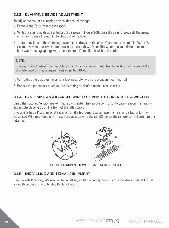
3.1.4 FASTENING AN ADVANCED WIRELESS REMOTE CONTROL TO A WEAPON
Using the supplied Velcro tape (A, Figure 3-4), fasten the remote control (B) to your weapon in an easily accessible place (e.g., on the front of the rifle stock).If your rifle has a Picatinny or Weaver rail on the front end, you can use the Picatinny adaptor for the Advanced Wireless Remote (C). Install the adaptor onto the rail (D). Insert the remote control unit into the adapter.
FIGURE 3-4. ADVANCED WIRELESS REMOTE CONTROL
A
B
B
C
D
3.1.5 INSTALLING ADDITIONAL EQUIPMENT
Use the side Picatinny/Weaver rail to install any additional equipment, such as the Armasight DT Digital Video Recorder or the Extended Battery Pack.

21ARMASIGHT by FLIRZEUS U S E R M A N U A L
3.1.6 CONNECTING AN ADDITIONAL EQUIPMENT
CAUTION:
Turn off the Zeus before you begin connecting/disconnecting any external equipment and before removing the batteries.
Remove the connector protective cap.Connect a cable of Digital Video Recorder or the Extended Battery Pack to the Zeus connector.
Use the plug A (Figure 3-6) of a video cable to connect an external video recorder/monitor/TV to the Zeus. Connect the plug C of a video cable to the Zeus connector.Use the plug B of a video cable to connect an external power source (6VDC/ 600mA) to the Zeus. Connect the plug C of a video cable to the Zeus connector.
AB
FIGURE 3-6. VIDEO CABLE
C
NOTE:The external power supply must have a standard OD double-pole socket with a positive center contact.
CAUTION:After removing the cable, replace the protective cap over the connector.
FIGURE 3-5. DIGITAL RECORDER INSTALLATION

22 ARMASIGHT by FLIRZEUS U S E R M A N U A L
3.2 CONTROLS AND DISPLAY INDICATIONS
3.2.1 CONTROLS
CAUTION:DO NOT force the equipment controls past their stopping points.
The Zeus controls are shown in Figures 3-7 and 3-8 and are defined in Tables 3-1 and 3-2. The ITEM NO. columns of the tables indicate the numbers used to identify items in the figures.
NOTE:Various display symbols indicating the current operating state of the Zeus can be displayed permanently, may appear momentarily, or can be set to appear only when a certain function is activated.
TABLE 3-1. CONTROLS AND INDICATORSITEM NO. CONTROL/INDICATOR FUNCTION
1 Eyepiece Focus Ring Adjusts the eyepiece diopter.
2 Turn-Pull Switch Activates the Zeus when turned to ON.NOTE:You must pull the knob before turning in order to use either the ON or STB.
Activates standby mode when turned to STB (see note above).
Deactivates the Zeus when turned to OFF.
3 Control Panel Buttons Configures operational settings. See Table 3-2 for button functions.
4 Objective Focus Ring Focuses the objective lens. Adjusts for sharpest view of the scene.
1
23 4
5
FIGURE 3-7. CONTROLS

23ARMASIGHT by FLIRZEUS U S E R M A N U A L
ITEM NO. CONTROL/INDICATOR FUNCTION
5 Remote Control Button
Activates/deactivates the Zeus in standby mode. To turn the unit on, press button once, to turn it off – press button again.To operate the device in short-time activation mode, press and hold the remote control button down for 1.5+ seconds. Release the remote control button to deactivate the device.
— Battery Status Indicator (a battery icon in the top right hand part of the display)
The color fill (green/yellow/red) bar in the battery icon indicates the current power level of the internal battery, or remaining battery life.
The totally shaded battery icon indicates the fully charged battery.
The flashing transparent battery icon indicates a low battery.
The Zeus button control panel is shown in Figures 3-8. Table 3-2 contains the button functions and their brief descriptions. The ITEM NO. column of the table indicates the number used to identify buttons in Figure 3-8.
NOTE:
Each button is responsible for some functions selected by briefly pushing or holding down the button, or using the button in combination with a second one (as described in Table 3-2).Pushing a button for 1.5+ second is considered “holding down.”
1
3
4
5
2
FIGURE 3-8. BUTTON CONTROL PANEL
TABLE 3-1. CONTINUED

24 ARMASIGHT by FLIRZEUS U S E R M A N U A L
TABLE 3-2. BUTTON CONTROLSITEM NO. FUNCTION DESCRIPTION
1, 3
Display Brightness Control
Push the button (1) to increase the screen brightness or push the button (3) to decrease the screen brightness.
Image Palette Control
To scroll up through the available palettes push and hold button (1) or (3) to scroll down or up respectively. There are 13 palettes available: White Hot, Black Hot, Fusion, Rainbow, Globow, Ironbow1, Ironbow2, Sepia, Color1, Color2, Ice-Fire, Rain and OEM.
User-Controlled Manual Non-Uniformity Correction/ Flat-Field Correction (UCMNUC/FFC)
Simultaneously holding down buttons (1) and (3) induces manual User-Controlled Manual Non-Uniformity Correction/Flat-Field Correction (UCMNUC/ FFC).
Up, Down Use the UP (1) and DOWN (3) buttons to navigate through the items on the menu.
2Digital Zoom Control To change the zoom progressively, push button (2).
Reticle on/ off Pushing and holding button (2) to reticle ON/OFF.
4
Reticle Color Control To change the reticle color, push button (4). There are four colors available of the reticle: black, white, red and cyan.
Reticle Pattern Control
To scroll through the reticle types, push and hold button (4). There are five types of reticles available: “Dot 4 MOA”, “Line Dot”, “Cross Center Dot”, “Cross”, “Crosshair”.
2, 4Reticle Position Zeroing
Simultaneously holding down buttons (2) and (4) zeroes the reticle position to the center of the screen.
Left, Right Use the LEFT (4) and RIGHT (2) buttons to navigate through the items on the menu.
5
Selection Push the SELECTION button (5) to view the settings available for the item selected.
MAIN Menu Pushing and holding button (5) will bring up the Main Menu selection. The menu includes the following functions: Palette, Reticle, Boresight, Enhancement, and Settings.
UCMNUC/ FFC Process Interruption
Pushing button (5) when the countdown is on the screen will cancel the UCMNUC/ FFC and the shutter will not interrupt viewing.

25ARMASIGHT by FLIRZEUS U S E R M A N U A L
3.2.2 MAIN MENU
Most setup options can be accessed from the MAIN MENU. To display the MAIN MENU, push and hold down the MENU button (5) on the control panel (Figure 3-9).
Once the MAIN MENU is displayed (Figure 3-10), use the UP and DOWN buttons (Figure 3-9) to navigate through the items on the menu.Push the SELECTION button to view the settings available for the item selected.
NOTES:Navigate through submenu items by pushing the UP and DOWN button, except where otherwise expressly indicated. The LEFT and RIGHT buttons are available only when specified on the menu screen with < > symbols.After a menu item is selected, push the SELECTION button to make the selected setting/ activate the selected function.Select the EXIT item and then push the SELECTION button to return to the MAIN MENU.
> EXIT PALETTE RETICLE BORESIGHT ENHANCEMENT SETTINGS
MAIN MENU
FIGURE 3-10. MAIN MENU
(1) UP
(3) DOWN
(4) LEFT
(5) SELECTION (2) RIGHT
FIGURE 3-9. MAIN MENU NAVIGATION BUTTONS

26 ARMASIGHT by FLIRZEUS U S E R M A N U A L
Palette Menu
The PALETTE menu (Figures 3-11 and 3-12) allows the user to select from a choice of temperature imaging modes: White Hot, Black Hot, Fusion, Rainbow, Globow, Ironbow 1, Ironbow 2, Sepia, Color 1, Color 2, Ice-Fire, Rain, and OEM Custom.
NOTE:To navigate through the items on the two-page PALETTE menu, hold down the UP/ DOWN button.
The palettes act as color templates for visualizing temperature changes in the scene.
> EXIT WHITE HOT BLACK HOT FUSION RAINBOW GLOBOW IRONBOW1 IRONBOW2
PALETTE
FIGURE 3-11. PALETTE MENU. PAGE 1
> EXIT SEPIA COLOR 1 COLOR 2 ICE - FIRE RAIN OEM CUSTOM
PALETTE
FIGURE 3-12. PALETTE MENU. PAGE 2
NOTE:
The most popular palettes are White Hot and Black Hot, usually known as inversion. White Hot mode is good for spotting targets, while Black Hot mode is most useful for situational reading.
NOTE:Training and experience are required to quickly and properly interpret the thermal image being displayed.

27ARMASIGHT by FLIRZEUS U S E R M A N U A L
Reticle Menu
The RETICLE menu (Figure 3-13) allows the user to select from a choice of reticle patterns: Dot type, Line Dot, Crosshair Center Dot, Crosshair.To navigate through the items on the RETICLE menu, push and hold down the LEFT/ RIGHT button.
> EXIT
<> CROSS
RETICLE
FIGURE 3-13. RETICLE MENU
Boresight Menu
The BORESIGHT function allows the user to changing the reticle position in the display.
NOTE:Remember that the center of impact on the target shifts in the opposite direction from the direction that the reticle shifts. So, to bring the center of impact to the right/left and up/down, you must shift the reticle to the left/right and down/up, respectively.
Figure 3-14 shows the boresight screen.
To control the reticle shifting, check the running reticle center coordinates, which are printed in the lower left hand corner of the display.
NOTE:For display coordinates, the origin is the center of the display. The running coordinate of the reticle is the number of incremental shifts of the reticle from the center of the display. The minus sign appears before the displayed number when the reticle shifts left or down (the point of impact (POI) on the target shifts right or up, respectively).
> EXIT
WINDAGE <> 10 ELEVATION <> -5
BORESIGHT
FIGURE 3-14. BORESIGHT MENU

28 ARMASIGHT by FLIRZEUS U S E R M A N U A L
Push the LEFT and RIGHT buttons to adjust for windage. Moving the reticle in the positive direction (to the right) will move the POI to the left. Moving the reticle in the negative direction (to the left) will move the POI to the right. Push the UP and DOWN buttons to adjust for elevation. Moving the reticle in the positive directly (up) will move the POI down. Moving the reticle in the negative direction (down) will move the POI up.
Every time one of these buttons is pushed, the reticle shifts a single pixel increment corresponding to the minimum boresight correction value, and the point of impact on the target moves according to the specified windage/elevation boresight increment, in the opposite direction to that of the shifting reticle. Every time one of these buttons is pushed for 3 sec, then the reticle begins to shift in 4 pixels increments untill you let go. Holding down the combination of buttons (LEFT+RIGHT) to reset to zero azimuth and elevation the reticle will shift to the display center.
Enhancement Menu
The ENHANCEMENT menu (Figure 3-15) settings allow the user to take advantage of advanced signal processing algorithms to improve the quality of the picture that is being viewed under a variety of different thermal environments.
CONTRAST - Active Contrast Enhancement (ACE) – a digital contrast correction that allows for a smart scene optimization based on dynamic adjustments where a variety of contrast levels occur depending on relative scene temperature. The adjustment range is from -8 to +8 with default value 4. Lower values will make hotter objects get more contrast and higher values will make a colder objects get more contrast.
ENHANCEMENT
> EXIT CONTRAST <> 4 SHARPNESS <> 60 SMARTSCENE <> 15 GAIN <> 35 AGC SPEED <> 12
FIGURE 3-15. ENHANCEMENT MENU
FIGURE 3-16. DIGITAL CONTRAST CORRECTIONCONTRAST -8 CONTRAST +8

29ARMASIGHT by FLIRZEUS U S E R M A N U A L
SHARPNESS - Second Generation Digital Detail Enhancement (DDE) – a sharpness correction that is digitally enhances the picture to present clearer imagery, significantly improves edge sharpening and further reduces image noise. The adjustment range is from -20 to +100 with default value 60. Lower values will create an object image with softer edges. Higher values will make an object sharper, enhance details and will further increase the signal to noise ratio.
SMART SCENE - Smart Scene Optimization (SSO) – a fine-tuning computational correction that significantly improves an overall visual acuity for targets that have thermal signatures similar to a surrounding background. Higher values provide a more linear automatic gain control behavior and objects with similar, but not the same temperature can be differentiated with greater accuracy. The adjustment range is from 0 to 100 with default value 15.
GAIN - Automatic Gain Control (AGC) – a correction that used to automatically adjust the gain to an appropriate range, the weaker the image signal, the stronger the gain. The adjustment range is from 0 to 255 with default value 35.
FIGURE 3-17. SHARPNESS CORRECTIONSHARPNESS -20 SHARPNESS +100
FIGURE 3-18. SMART SCENE OPTIMIZATION
SMART SCENE 0 SMART SCENE 100

30 ARMASIGHT by FLIRZEUS U S E R M A N U A L
FIGURE 3-19. GAIN CORRECTIONGAIN 0 GAIN 35
AGC SPEED – parameter that allows user to control the refresh rate of Automatic Gain Control (AGC). The adjustment range is from 0 to 128 with a default value of 12.Settings Menu
The SETTINGS menu (Figure 3-20) allows direct changes to the save rifle profiles, video standard, display left margin, display top margin, and factory default setting. The RIFLE PROFILE function allows the user to boresight the Zeus to the weapon and then save the boresighted reticle position map in the “Rifle Profile” tab. This can be done for the same scope equipped to up to 3 different rifles (Profile 1, Profile 2, and Profile 3). The STANDARD function allows the user to select from a choice of NTSC or PAL video standard.The LEFT MARGIN function allows the user to move the display left/right by a fixed number of pixels. The TOP MARGIN function allows to move the display up/down by a fixed number of pixels.The SETTINGS menu also includes factory software revision information under FW: (firmware).
> EXIT RIFLE PROFILE STANDARD LEFT MARGIN TOP MARGIN FACTORY DEFAULTS FW: (factory software revision)
SETTING
FIGURE 3-20. SETTINGS MENU
NOTE:
After configuration is complete, select EXIT on the MAIN MENU and push the SELECTION button to leave the MAIN MENU. All settings will be saved.

31ARMASIGHT by FLIRZEUS U S E R M A N U A L
3.3 OPERATING PROCEDURES 3.3.1 OPERATING
WARNING:
Always make sure your firearm is unloaded before you place the scope on the firearm. Reconfirm that the chamber is empty if you stop the procedure then resume later. Safe handling rules should be followed at all times.
CAUTION:
DO NOT force the equipment controls past their stopping points.
CAUTION:
To prevent thermal damage to the equipment, never point it, either powered or not, directly at the sun or any other source of high intensity light that the unprotected human eye cannot tolerate (such as a welding arc). To prevent inadvertent exposure to these sources, never leave the equipment without the objective lens cap secured.
Operating procedures are as follows:1. Remove the Zeus from the carrying case.
2. Install the Zeus on the weapon’s Picatinny/Weaver rail.
3. Verify that the Zeus is securely mounted to the weapon.
4. Remove the objective lens cap.
5. Point the equipment at an object.
6. Activate the Zeus by turning the turn-pull switch to the ON position. After approximately 3 sec, video of the thermal scene should appear.
7. Adjust the Zeus for your eyesight by turning the eyepiece focus ring CW up to the stop, and then CCW until the display and symbols (such as the reticle) are as clear as possible. Bring the object into focus by turning the objective focus ring (CW for far focus, CCW for near focus).
NOTE:
The total diopter adjustment range is covered with 2 turns of the eyepiece focus ring.The total focus range is covered with 3/4 turn of the objective focus ring.
8. Using the buttons on the control panel (Figure 3-21), configure the Zeus to adapt it to your situation.
For more information on operational setting procedures, see Part 3.2 (Controls and Display Indications).

32 ARMASIGHT by FLIRZEUS U S E R M A N U A L
A. Adjust the brightness of the display for your comfort.
Momentarily push the brightness adjustment buttons to increase (1) /decrease (3) the display brightness by one level at a time until you reach your desired brightness level.
B. Use UCMNUC/FFC (User-Controlled Manual Non-Uniformity Correction/Flat-Field Correction) function to improve image quality. As the camera including the detector heats up during the use, the detector pixels will drift. The pixels do not drift uniformly. The camera software compensates for the drift up to an accurate position point, but when the limit is reached the UCMNUC/FFC function is triggered. A uniform mechanical shutter is placed between the lens and the detector for a moment and the signal is processed.
Push and hold the two brightness control buttons (1) and (3) at the same time to manually trigger a User-Controlled Manual Non-Uniformity Correction/Flat-Field Correction.
If necessary, interrupt the automatic UCMNUC/FFC process by pushing the central button (5) on the control panel during the 5 second countdown which appears at the bottom of the display.
C. Adjust the necessary adjustment using the MAIN MENU. See Part 3.2.2 (Using the MAIN MENU).
NOTE:
After configuration is complete, select EXIT on the MAIN MENU and push the SELECTION button to leave the MAIN MENU. All settings will be saved.
D. Select the color of the reticle.
Momentarily push the reticle color control button (4) to select among black, white, red, and cyan.
E. Turns reticle ON/ OFF.
Push and hold button (2) to turn reticule ON or OFF.
F. Select a reticle pattern.
Push and hold button (4) to select from a choice of reticle patterns: “Dot 4 MOA,” “Line Dot,” “Cross Center Dot,” “Cross,” “Crosshair” (Figure 3-22).
FIGURE 3-21. SETTING BUTTONS
(1) BRIGHTNESS UP/PALETTE (FWD)
(3) BRIGHTNESS DOWN / PALETTE (BWD)
(4) RETICLE COLOR / RETICLE PATTERN
(2) DIGITAL ZOOM / RETICLE ON/ OFF

33ARMASIGHT by FLIRZEUS U S E R M A N U A L
NOTE:
The reticles appear in the most recently saved position on the display.
G. Use digital zoom to magnify the central area of the displayed scene.
Momentarily push the zoom control button (2) to slowly magnify into the displayed scene. The 2x, 4x, 8x symbols (maximum zoom factor is dependent of model) will appear in the top part of the display.
NOTE:
Digital zoom allows distant objects to appear larger; however, the resolution will be compromised.
NOTE:Zooming does not affect the boresight.
NOTE:Digital zoom and reticle color control help target detection and discrimination.
9. To align the barrel of the weapon, place the reticle on the desired target. To allow for the bullet’s travel (i.e. bullet drop, windage, and the target mobility), use the boresight adjusting buttons.
10. To operate the Zeus with Advanced Wireless Remote Control (AWREC), turn the function switch to the STB position (Standby). After it the Remote Control button can activate/ deactivate the device in two ways:
1) To turn the device on, press the remote control button once, to turn it off – press the button again.
FIGURE 3-22. RETICLE PATTERNS
DOT 4 MOA LINE DOT CROSS CENTER
DOT CROSS CROSSHAIR NO RETICLE

34 ARMASIGHT by FLIRZEUS U S E R M A N U A L
2) To operate the device in short-time activation mode (see note below), press and hold the remote control button down for 1.5+ seconds. Release the remote control button to deactivate the device.
NOTE:
Devices manufactured before 2016 do not have the short-time activation mode.
CAUTION:
DO NOT leave the equipment activated when not in use.
3.3.2 BORE SIGHTING THE ZEUS
WARNING:
Always make sure your firearm is unloaded before you place the scope on the firearm. Reconfirm that the chamber is empty if you stop the procedure then resume later. Safe handling rules should be followed at all times.
NOTE:The Zeus must be zeroed each time it is mounted to a new weapon.
NOTE:When reticle at (0-0) coordinates there is an incline of 15 arc minutes for the scope’s optical axis.
Boresight the Zeus as follows:1. Locate a target at the fire adjustment range (100yd or 100m for example).
2. Turn on the Zeus.
3. Adjust the eyepiece and focus the objective lens to sharpen the image of the target.
4. Adjust the brightness of the display.
5. Select a reticle pattern.
6. Take aim by centering the reticle on the target and fire a series of shots (3-4).
7. Find the point of impact and measure its vertical and horizontal deviations from the center of the target.
8. Work out the values of boresight correction required to compensate for the measured deviation of the point of impact from the center of the target. Table 3-3 contains examples of calculating boresight correction values.

35ARMASIGHT by FLIRZEUS U S E R M A N U A L
TABLE 3-3. EXAMPLE OF CALCULATING BORESIGHT CORRECTIONS (100YD AND 100M FIRE RANGES)
MODEL ZEUS 336 3-12x50 ZEUS 336 5-20x75 ZEUS 640 3-24x75 ZEUS 640 3-24x75
Boresight Increment * 0.6in / 100yd(1.7cm / 100m)
0.35in / 100yd(1cm / 100m)
1.2in / 100yd(3.3cm / 100m)
0.65in / 100yd(1.8cm / 100m)
Measured Windage/ Elevation Deflection of the Point of Impact from the Target Centre (for example)
2in / 1in (5cm / 2cm)
4in / 3in (10cm / 7cm)
5in / 10in(13cm / 25cm)
7in / 2in (18cm / 5cm)
Correction Value
Windage 2/0.6≈3 shifts (5/1.7≈3 shifts)
4/0.35≈11 shifts (10/1=10 shifts)
5/1.2≈4 shifts (13/3.3≈4 shifts)
7/0.65≈11 shifts (18/1.8=10 shifts)
Elevation 1/0.6≈1 shif (2/1.7≈1 shif)
3/0.35=8 shifts (7/1=7 shifts)
10/1.2≈8 shifts (25/3.3≈8 shifts)
2/0.65≈3 shifts (5/1.8≈3 shifts)
* 1) For PAL resolution (768x574).2) To calculate boresight increment value for a fire range R different from 100 yards, use the coefficient R/100.
So at a range R (in yards) the boresight increment is: 0.6×R/100, in — for Zeus 336 3-12x50;0.35×R/100, in — for Zeus 336 5-20x75; 1.2×R/100, in — for Zeus 640 2-16x50;0.65×R/100, in — for Zeus 640 3-24x75.
3) To calculate boresight increment value in metric units for a fire range R different from 100m, use the coefficient R/100. So at a range R (in meters) the boresight increment is:
1.7×R/100, cm — for Zeus 336 3-12x50; 1×R/100, cm — for Zeus 336 5-20x75; 3.3×R/100, cm — for Zeus 640 2-16x50;1.8×R/100, cm — for Zeus 640 3-24x75.
9. Use the BORESIGHT MENU to apply corrections required to bring the point of impact as close as possible to the center of the target. See Part 3.2.2 (Using the MAIN MENU).
A. Use LEFT and RIGHT buttons to adjust for windage. Moving the reticle in the positive direction (to the right) will move the point of impact to the left. Moving the reticle in the negative direction (to the left) will move the point of impact to the right.
B. Use UP and DOWN buttons to adjust for elevation. Moving the reticle in the positive directly (up) will move the point of impact down. Moving the reticle in the negative direction (down) will move the point of impact up.
10. Fire a series of shots to check the boresight.
11. After completing the boresight adjustment procedure you can use RIFLE PROFILE function of Setting menu to save the boresighted reticle position map in the “Rifle Profile” tab. This can be done for the same scope equipped to up to 3 different rifles (Profile 1, Profile 2, and Profile 3).
12. Turn off the Zeus and place the cap over the objective lens.

36 ARMASIGHT by FLIRZEUS U S E R M A N U A L
3.3.3 ZEUS SHUT-DOWN
NOTE:
Shut down the Zeus properly to avoid losing unsaved settings and data.
Shut-down the Zeus as follows:1. Be sure to save your settings and data.
2. Turn off the Zeus.
3. Replace the cap on the objective lens.
4. Disconnect the cable (if applicable).
5. Place the cap on the connector.
6. Dismount the Zeus from the weapon.
7. Remove the batteries.
CAUTION:
Do not store the Zeus with the batteries still in it.
8. Store the Zeus and all accessories in the carrying case.

37ARMASIGHT by FLIRZEUS U S E R M A N U A L
SECTION 4
MAINTENANCE AND TROUBLESHOOTING
4.1 PREVENTIVE MAINTENANCE CHECKS AND SERVICESTable 4-1 Preventive Maintenance Checks and Services (PMCS), has been provided so that you can keep your equipment in good operating condition.Perform functional tests in the order listed in Table 4-1.Operating procedures are detailed in Chapter 3.
Explanation of Table Entries:SEQ NO. column. Sequence numbers are for reference and appear in the order required to perform checks and services.LOCATION OF ITEM TO CHECK/ SERVICE column. Indicates the location and the item to be checked or serviced.PROCEDURE column. Details the check/ service procedure.NOT FULLY MISSION CAPABLE IF... column. Indicates what faults will prevent your equipment from operating successfully.
TABLE 4-1. PREVENTIVE MAINTENANCE CHECKS AND SERVICES
SEQ NO.
LOCATION OF ITEM TO CHECK/
SERVICEPROCEDURE NOT FULLY MISSION
CAPABLE IF...
PRE-OPERATION CHECKS1 Completeness Open storage/carrying case and inventory items
by means of comparing with the data specified in this manual.
Missing items.
2 Soft Carrying Case
Shake out loose dirt or foreign material. Inspect for tears, cuts, excess wear or damage.
3 Body Inspect for cracks or damage. Scratches and gouges are OK if operation is not affected. Inspect for missing parts.Clean as required.
Cracked or damaged. Missing parts.
4 Objective Lens Cap
Inspect for cuts, tears and dirt.Clean as required.
Cap is torn or cut. Cap is not secured to the housing of the lens.

38 ARMASIGHT by FLIRZEUS U S E R M A N U A L
SEQ NO.
LOCATION OF ITEM TO CHECK/
SERVICEPROCEDURE NOT FULLY MISSION
CAPABLE IF...
5 Eyecup Inspect for cuts, tears and dirt. Inspect for torn, bent or improperly fitting eyecup.Clean as required.
Cup is torn or cut.
6 Battery Compartment and Cap
Inspect for corrosion, moisture, and corroded or defective contacts. Inspect for cap damage or retainer breaks. Inspect rubber gasket for damage.
Contacts are damaged or corroded. Retainer is broken. Cap or rubber gasket is damaged.
7 Lenses Inspect for cleanliness, scratches, chips or cracks.Clean as required.
Chipped or cracked. Scratches hinder vision through the equipment.
8 Objective Focus Ring
Rotate objective focus ring to ensure it is not too tight or too loose. Range is approximately 3/4 turns.
Ring gets stuck, is too loose, or adversely affects the user’s ability to properly focus the objective lens.
9 Eyepiece Focus Ring
Rotate eyepiece focus ring to ensure the ring is not too tight or too loose. Range is approximately 2 turns.
Ring gets stuck, is too loose, or adversely affects the user’s ability to properly adjust the diopter.
10 Turn-Pull Switch
Check for operation (without batteries). Switch is inoperative.
11 Connector Inspect for corrosion, moisture, and corroded or defective contacts. Inspect for cap damaged or retainer breaks.
Contacts are damaged or corroded. Cap is damaged. Retainer is broken.
12 Mount Inspect for damage or corrosion, for missing parts. Check for proper operation and attachment security.
Damaged. Missing parts. Clamping device is inoperative.
13 Remote Control Unit
Check for damage and missing parts. Check Velcro tape for wear.
Damaged. Missing parts.
14 Video Cable Inspect for damage. Inspect the cable connector for corrosion, moisture, and corroded or defective contacts. Clean as required.
Damaged.
OPERATIONAL CHECKSNOTE:For a complete operational checking, it is necessary to connect a video monitor to the Zeus.
15 Turn-Pull Switch
Install the batteries. Remove the objective lens cap. Point the equipment at an object. Turn the equipment on. Look for a thermal image on the display. Look for a flashing battery icon in the eyepiece viewing area.
No thermal image. Battery icon is flashing (indicates a low battery).
16 Control Board Ensure the scope is responsive to control buttons.
Unresponsive buttons.
TABLE 4-1. CONTINUED
39ARMASIGHT by FLIRZEUS U S E R M A N U A L
SEQ NO.
LOCATION OF ITEM TO CHECK/
SERVICEPROCEDURE NOT FULLY MISSION
CAPABLE IF...
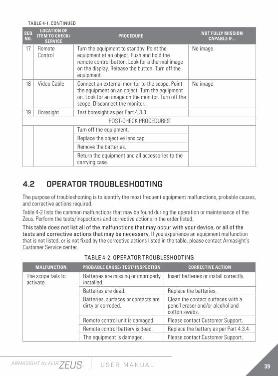
17 Remote Control
Turn the equipment to standby. Point the equipment at an object. Push and hold the remote control button. Look for a thermal image on the display. Release the button. Turn off the equipment.
No image.
18 Video Cable Connect an external monitor to the scope. Point the equipment on an object. Turn the equipment on. Look for an image on the monitor. Turn off the scope. Disconnect the monitor.
No image.
19 Boresight Test boresight as per Part 4.3.3.POST-CHECK PROCEDURES
Turn off the equipment.Replace the objective lens cap.Remove the batteries.Return the equipment and all accessories to the carrying case.
4.2 OPERATOR TROUBLESHOOTINGThe purpose of troubleshooting is to identify the most frequent equipment malfunctions, probable causes, and corrective actions required.Table 4-2 lists the common malfunctions that may be found during the operation or maintenance of the Zeus. Perform the tests/inspections and corrective actions in the order listed.This table does not list all of the malfunctions that may occur with your device, or all of the tests and corrective actions that may be necessary. If you experience an equipment malfunction that is not listed, or is not fixed by the corrective actions listed in the table, please contact Armasight’s Customer Service center.
TABLE 4-2. OPERATOR TROUBLESHOOTINGMALFUNCTION PROBABLE CAUSE/ TEST/ INSPECTION CORRECTIVE ACTION
The scope fails to activate.
Batteries are missing or improperly installed.
Insert batteries or install correctly.
Batteries are dead. Replace the batteries.Batteries, surfaces or contacts are dirty or corroded.
Clean the contact surfaces with a pencil eraser and/or alcohol and cotton swabs.
Remote control unit is damaged. Please contact Customer Support.Remote control battery is dead. Replace the battery as per Part 4.3.4.The equipment is damaged. Please contact Customer Support.
TABLE 4-1. CONTINUED

40 ARMASIGHT by FLIRZEUS U S E R M A N U A L
MALFUNCTION PROBABLE CAUSE/ TEST/ INSPECTION CORRECTIVE ACTION
The scope is not responsive to control buttons.
The equipment is damaged. Please contact Customer Support.
Remote control does not work.
Battery is missing or improperly installed.
Insert battery or install correctly.
Battery is dead. Replace the battery.
Battery surfaces or contacts are dirty or corroded.
Clean the contact surfaces with a pencil eraser and/or alcohol and cotton swabs.
Remote control unit is damaged. Please contact Customer Support.Poor image quality. Check objective lens and eyepiece
focus.Refocus.
Check for fogging or dirt on objective lens and eyepiece.
Clean the lenses as detailed in Part 4.3.2.
The equipment is damaged. Please contact Customer Support.No image on an external monitor.
Video cable is damaged. Replace the video cable with a new one. Please contact Customer Support.
The equipment is damaged. Please contact Customer Support.Hindered rotation of the battery cap.
Dirty cap thread. Clean the thread.Damaged cap thread. Replace the cap with a new one.
Please contact Customer Support.Light is visible around eyecup.
Check eyecup resilience. If the eyecup is defective, please contact Customer Support.
4.3 MAINTENANCE
4.3.1 GENERAL
The Zeus operator maintenance consists of operational tests, inspections for unit serviceability, cleaning and mounting procedures, corrective actions (troubleshooting and replacement of a limited number of parts). Maintenance instructions covered elsewhere in this manual (PMCS, troubleshooting, etc.) are not repeated in this section.
CAUTION:The Zeus is a precision electro-optical instrument and must be handled carefully at all times to prevent damage.
CAUTION:DO NOT dismantle the equipment.
TABLE 4-2. CONTINUED

41ARMASIGHT by FLIRZEUS U S E R M A N U A L
4.3.2 CLEANING PROCEDURES
Clean the Zeus and optional items as follows:1. Gently brush off any dirt from the equipment using only a clean, soft cloth.2. Moisten the cloth with fresh water and gently wipe the external surfaces (except for optical
surfaces).3. Dry any wet surfaces (except for optical surfaces) with another clean, dry soft cloth.4. Using a lens brush, carefully remove all loose dirt from optical surfaces (objective lens and
eyepiece).5. Slightly dampen a cotton swab with ethanol and lightly and slowly wipe optical surface. Clean the
optical surface by circular movements from the center to the edge, not touching the lens holder and changing cotton swab after each circular stroke. Repeat until the optical surface is clean.
6. Clean the battery contact surfaces and contact springs with a pencil eraser and/or alcohol and cotton swabs.
CAUTION:Thoroughly dry each item before replacing into the storage/ carrying case.
4.3.3 BORE SIGHTING
Perform the Zeus bore sighting:— When the Zeus is mounted to a new weapon for the first time;— After repair of the Zeus/ weapon;— As the need arises (in case of systematic inaccuracy and missing the target).Refer to Part 3.3.2 for boresight procedure.
4.3.4 BATTERY REMOVAL AND REPLACEMENT
Refer to Part 3.1.1 for battery installation procedures.Replace the remote control battery as follows:1. Using a screwdriver, unscrew the four screws (A, Figure 4-1) that secure the cover to the bottom of
the unit. Remove the cover.
FIGURE 4-1. ADVANCED WIRELESS REMOTE CONTROL BATTERY INSTALLATION
A
2. Replace the battery with new one (CR2032, 3V). Install the battery, aligning their polarity markings (+/-) with those embossed on the compartment.
3. Replace the cover and tighten the screws (A).

42 ARMASIGHT by FLIRZEUS U S E R M A N U A L
APPENDIX
LIST OF SPARE PARTS
The parts authorized by this list of spare parts are required for operator maintenance. The list includes parts that must be removed before replacing authorized parts.The PART NO. column indicates the primary number used by the manufacturer, which controls the design and characteristics of the item in terms of its engineering drawings, specifications, standards, and inspection requirement, to identify an item.
FIGURE A-1. ZEUS SPARE PARTS LIST
764
5
2
1
3
1211 13
14 15 16
8
109

43ARMASIGHT by FLIRZEUS U S E R M A N U A L
TABLE A-1. ZEUS SPARE PARTS LIST
ITEM NO. DESCRIPTION PART NO.
1 50mm Objective Lens Cap AZSOLC50
- 75mm Objective Lens Cap AZSOLC75
2 50mm Objective Lens Assembly AZSOLA50
- 75mm Objective Lens Assembly AZSOLA75
3 Connector Cap AZSCNCP
4 Battery Cap AZSBC
5 Turn-Pull Switch AZSSWT
6 Eyepiece Assembly AZSEPA
7 Eyecup AZSEC
8 Side Picatinny/Weaver Rail AZSRRL
9 Mount AZSQRM2
10 M5×8 Flat Head Socket Cap Screw AZS5X8SCR
11 Battery Cassette AZSBTCS
12 Advanced Wireless Remote Control ANVR000001
13 Picatinny Adapter for Advanced Wireless Remote Control ANRA000002
14 Video Cable AZSVCB
15 Operation and Maintenance Manual AZSOMM
16 Carrying Case AGSC000009

OUTDOOR & TACTICAL SYSTEMS
Equipment described herein is subject to US export regulations and may require a license prior to export. Diversion contrary to US law is prohibited. Imagery for illustration purposes only. Specifications are subject to change without notice. ©2018 FLIR Systems, Inc. All rights reserved. 05/07/2018
18-0608-OTS
99 Washington Street Melrose, MA 02176 Phone 781-665-1400Toll Free 1-800-517-8431
Visit us at www.TestEquipmentDepot.com