Embed Size (px)
Citation preview

ARIEL Payload Consortium
Doc Ref: ARIEL-MSSL-PL-ANA-001 Issue: 2.0 Date: 10-FEBRUARY-2017
ARIEL Mechanical Analysis Report Page i
ARIEL
Phase A Payload Study
ARIEL Mechanical Analysis Report
ARIEL-MSSL-PL-ANA-001
Issue 2.0
Prepared by: Date:
Tom Hunt (MSSL) Consortium Mechanical Lead
Checked / Approved by:
Date:
Paul Eccleston (RAL Space) Consortium Project Manager

ARIEL Payload Consortium
Doc Ref: ARIEL-MSSL-PL-ANA-001 Issue: 2.0 Date: 10-FEBRUARY-2017
ARIEL Baseline Telescope Optical Prescription Page ii
DOCUMENT CHANGE DETAILS
Issue Date Page Description Of Change Comment 1.0 08/05/16 All Document created for MCR 2.0 10/02/16 All Document re-written for MSR

ARIEL Payload Consortium
Doc Ref: ARIEL-MSSL-PL-ANA-001 Issue: 2.0 Date: 10-FEBRUARY-2017
ARIEL Baseline Telescope Optical Prescription Page iii
DISTRIBUTION LIST EChO Payload Consortium External
Co-PIs / Science Team Coordinators
Study Engineering Team Working Group Leads
European Space Agency
Giovanna Tinetti Paul Eccleston Goren Pilbratt Hans Ulrik Nørgaard-Nielsen Kevin Middleton Ludovic Puig Jean-Philippe Beaulieu Emanule Pace Astrid Heske Paul Hartogh Gianluca Morgante Giusi Micela Tom Hunt Ignasi Ribas Enzo Pascale Enzo Pascale Pino Malaguti Mark Swain Jean-Louis Augueries Tanya Lim Neil Bowles Enzo Pascale Gillian Wright Graziella Branduardi-Raymont Marc Ollivier Other Engineering Team Pierre-Olivier Lagage As necessary for doc Vince Coudé du Foresto Athena Coustenis Emanuele Pace Giuseppe Piccioini Giuseppe Malaguti Alessando Sozzetti Maria Rosa Zapataro Osorio Mercedes Lopez-Morales Enric Palle Christopher Jarchow Denis Grodent Allan Hornstrup Geza Kovacs Pierre Drossart
ARIEL Payload Consortium
Doc Ref: ARIEL-MSSL-PL-ANA-001 Issue: 2.0 Date: 10-FEBRUARY-2017
ARIEL Baseline Telescope Optical Prescription Page iv
TABLE OF CONTENTS
Distribution List ...................................................................................................................... iii
Table of Contents .................................................................................................................. iv
1 Introduction ................................................................................................................... v
1.1 Scope ...................................................................................................................................... v
1.2 Units ........................................................................................................................................ v
1.3 Applicable Documents ............................................................................................................... v
1.4 Reference Documents ............................................................................................................... v
2 FINITe Element Model ................................................................................................... 1
2.1 Main Structure .......................................................................................................................... 1
2.2 V-Groove Mechanical Design .................................................................................................... 2
2.3 FE model Detailed Description ................................................................................................... 3
2.4 FE Model Item Masses .............................................................................................................. 5
3 Consortium CAD Model ................................................................................................ 11
3.1 Model Description ................................................................................................................... 11
4 Conclusion .................................................................................................................. 15

ARIEL Payload Consortium
Doc Ref: ARIEL-MSSL-PL-ANA-001 Issue: 2.0 Date: 10-FEBRUARY-2017
ARIEL Baseline Telescope Optical Prescription Page v
1 INTRODUCTION
1.1 SCOPE This document describes the mechanical design of the ARIEL system which includes all hardware above the SVM including the mounting struts and V-Grooves. The finite element model builds upon that constructed for the MSR, to include the detail designs of the subsystems. The CAD design incorporates the current optical design upon which the mechanical components are modelled and positioned to give an overall layout of the system. The CAD model incorporates the sub-system models where available and common optic mounts are shown to provide place holders for volume estimations. The model shows that the Ariel design has reached a good level of maturity and shows that a viable and cohesive design has been achieved.
1.2 UNITS All units are in SI unless stated otherwise.
1.3 APPLICABLE DOCUMENTS AD # APPLICABLE DOCUMENT TITLE DOCUMENT ID ISSUE / DATE
1 ARIEL Finite Element Model ARIEL-MSSL-MOD-001
2.0
2 ARIEL CAD Model ARIEL-MSSL-MOD-002
3.0
3
1.4 REFERENCE DOCUMENTS RD # REFERENCE DOCUMENT TITLE DOCUMENT ID ISSUE / DATE
1 ARIEL Payload Definition Document ESA-ARIEL-EST-PL-DD-001
2.0 / 15/02/17
2 3

ARIEL Payload Consortium
Doc Ref: ARIEL-MSSL-PL-ANA-001 Issue: 2.0 Date: 10-FEBRUARY-2017
ARIEL Baseline Telescope Optical Prescription Page 1
2 FINITE ELEMENT MODEL From the information given in the PDD (RD1) the coordinate system is defined as such: X is the pointing axis of the telescope. The telescope is a horizontal configuration mounted from the SVM. Z axis is the launch symmetry axis (vertical) and the Y axis completes the right handed triad. This is the same in the FEM (AD1).
The Finite Element Model is constructed from shell and beam elements. These elements provide and efficient modelling strategy for the large scale model of the PLM. This style of modelling also allows for rapid changes in order to carry out sensitivity analyses. RBE2 elements are used for primary links to simulate joint stiffness and ensure loads are distributed where beams are joined to shell elements. All bi-pod mountings are simulated using GFRP main tubes which provide rigid support while carrying out the function of thermal isolation of main components. The ends of the bi-pod mounts are represented by titanium flexures to ensure bending is not introduced to the mounting. The FEM is made to be as representative as possible of the current mechanical design, however sub-system instrument boxes are represented as lumped masses. Non-structural mass is used to bring the components up to their final mass including maturity margin.
The FEM incorporates a representative light weighted version of the M1, M1 whiffle tree mounts and the telescope optical bench. The baffle and V-grooves are planned to be constructed from aluminium honeycomb material. The honeycomb is modelled as a solid plane but with reduced stiffness and reduced density from that of the parent material. This is currently used in order to provide efficient modelling. Once detailed designs of these components are completed more representative honeycomb could be modelled and provide a correlated input to the system FEM. Details of the optics chain are not modelled beyond M2 as this is currently too detailed for the model. In this model the Baffle is assumed to be a non-structural item which surrounds the main telescope structure. The model carries all mass margins using the CBE taken from the PDD (RD1).
2.1 MAIN STRUCTURE The overall structure of the Ariel Telescope follows a classical horizontal design where the telescope is supported from the SVM on three thermally isolating, isostatic bi-pod mounts. The main structure, which is made entirely from aluminium consists of a telescope optical bench (TOB), the telescope beam and telescope stiffening tubes. The two main rear bi-pods support the TOB, from which the M1 is carried by 3 whiffle tree mountings. The rear of the TOB houses the instrumentation of the mission.
Figure 1: PLM Structure with baffle removed
The instrument casing has been incorporated into the TOB to provide additional structural depth to improve the optical bench stiffness. The lid of the instrument casing forms the main instrument radiator,

ARIEL Payload Consortium
Doc Ref: ARIEL-MSSL-PL-ANA-001 Issue: 2.0 Date: 10-FEBRUARY-2017
ARIEL Baseline Telescope Optical Prescription Page 2
this provides passive cooling of the payload in order to get the instrumentation to an operating temperature or to where they can be actively cooled.
Inside the instrument casing are the common optics of the ARIEL system including two dichroic beam splitters and FGS, a calibration light source, 4 folding mirrors and the AIRS system (Ariel Infra-Red Spectrometer). Cooling heads for the AIRS system are mounted onto the detectors and cooled via refrigeration tubes which run back to the cooler compressors in the SVM.
The M2 is supported at the end of the telescope beam and is attached to a focussing mechanism.
The telescope itself is surrounded by a baffle which can potentially be used for additional cooling and shades the optical components from stray light. This telescope baffle is not considered to be a structural item and mounts from the telescope stiffening tubes.
The telescope stiffening tubes have been added since the MCR and reduces the twisting of the telescope beam during transverse modal vibrations (in the Y axis). The stiffening tubes are also to be made in aluminium to ensure even thermal contraction of the entire system which is important for maintaining room temperature optical alignment at cold temperatures.
Figure 2: Main PLM structure of FE Model – baffle removed
2.2 V-GROOVE MECHANICAL DESIGN The V-Groove radiators are the next component which are likely to provide a low frequency structural response. These radiators require a large area and must be supported using thermally isolating mounts. The panels are constructed from aluminium honeycomb in order to achieve stiffness and light weight whilst providing a large radiating surface. The V-grooves and SVM top plate also provide shading to the PLM to ensure there is no direct line of sight from the sun to the PLM. All PLM services need to pass through the V-grooves however this is not modelled within the FEM or the CAD model at this time.
The V grooves are supported on 8 thermally isolating tubes which will be made for GFRP tubes. The diameter of these tubes has been increased since the MCR in order to cope with the additional mass of the larger V-groove surface area (due to SVM increasing in size). These tubes are of a larger diameter but of thin wall thickness so that the same cross sectional area can be achieved. The increased tube diameter ensures that the lateral modes of the V-grooves are higher than those required for the specified launch environment. As seen later in the model the V-grooves begin to flutter before the struts begin to allow the shield to move laterally.
The V-grooves are modelled as three separate shells supported by beam elements. The shell is modelled at the correct thickness but assumes a significantly lower stiffness than the aluminium (30GPa). This
ARIEL Payload Consortium
Doc Ref: ARIEL-MSSL-PL-ANA-001 Issue: 2.0 Date: 10-FEBRUARY-2017
ARIEL Baseline Telescope Optical Prescription Page 3
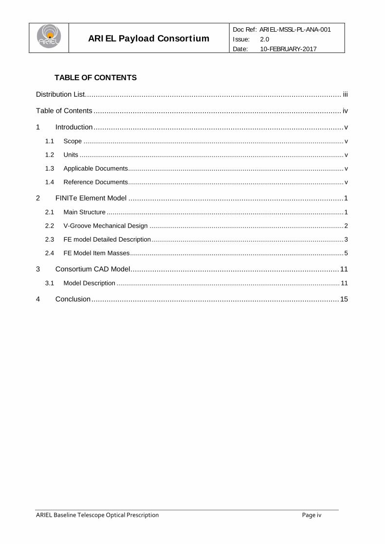
allows for efficient modelling when initially sizing these components. Modelling individual cells is unnecessary for a model of this scale.
From the design study the V-grooves have been estimated to have an overall mass of 64kg including a 20% maturity margin which includes all of the necessary supports and feedthroughs for PLM services.
Figure 3: PLM and V-Groove CAD Model
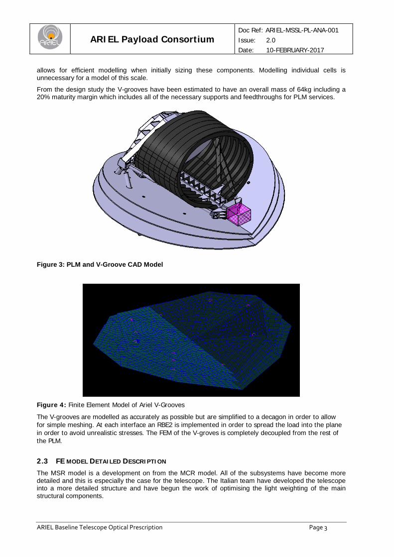
Figure 4: Finite Element Model of Ariel V-Grooves
The V-grooves are modelled as accurately as possible but are simplified to a decagon in order to allow for simple meshing. At each interface an RBE2 is implemented in order to spread the load into the plane in order to avoid unrealistic stresses. The FEM of the V-groves is completely decoupled from the rest of the PLM.
2.3 FE MODEL DETAILED DESCRIPTION The MSR model is a development on from the MCR model. All of the subsystems have become more detailed and this is especially the case for the telescope. The Italian team have developed the telescope into a more detailed structure and have begun the work of optimising the light weighting of the main structural components.

ARIEL Payload Consortium
Doc Ref: ARIEL-MSSL-PL-ANA-001 Issue: 2.0 Date: 10-FEBRUARY-2017
ARIEL Baseline Telescope Optical Prescription Page 4
The consortium model is constructed from scratch using the CAD data to inform where stiffeners and major components are placed. Some simplifications have been implemented in order to make the modelling more efficient but in all cases these are likely to make the model more conservative. Some stiffeners are not included to simplify modelling and all mass margin is carried on each sub-system. All components within the instrument housing are represented by lumped masses that are positioned in the correct places to ensure the mass distribution and offsets are correct.
The telescope design team have carried out analysis on just the telescope and the consortium model provides details of the behaviour of the structure with all of the other sub-systems in place. Detailed work such as the thermos-elastic response is all carried out within the telescope model and the overall structural behaviour is presented here.
The masses used for the model are taken from the most up to date estimates which have been compiled from the individual design teams. A table comparing the FEM masses with that of the mass estimate are given in table 2.
The design for the ARIEL telescope is in aluminium, this is planned to be manufactured within the consortium. The aluminium design is seen as a lower risk with only marginal mass penalties. At this stage further light weighting can be investigated and a conservative approach has been taken in order to prove viability. Due to the lower risk and using more standard manufacturing techniques it is believed the assembly can be manufactured at significantly lower cost. The masses used within the FEM model are as follows:
Item CBE Mass (kg) Nominal Mass (with 20% contingency) Allocation
Telescope Subsystem 263.3 300.0 TOB* 106.6 111.9 5
Telescope Beam 29.2 35.0 20 Telescope Baffle 12.0 14.4 20
Telescope Heaters, Harness 6.0 7.2 20 M1 85.0 102.0 20
M1 Supports 16.9 20.2 20 M2 1.5 1.8 20
M2 Refocus Mechanism 5.0 6.0 20 M3 0.2 0.2 20
M3 Mounting 1.0 1.2 20 Instrument Subsystems
FGS 1.6 2.0 25 AIRS 7.7 9.3 25
Common Optics + Calibration source 2.0 2.4 20
Instrument Radiator 6.0 7.2 20 Instrument Enclosure 0.0 0.0 20 JT Cooler Cold Head 1.5 1.8 20
Payload Cryogenic Harnesses 6.5 7.8 20 Thermal Shield Assembly
PLM Support Struts 16.0 19.2 20 V-grooves 53.3 64.0 20 PLM Total: 357.9 413.6
Table 1: Masses taken from design consortium based upon up to date design predictions
The payload warm units which account for around 32kg (CBE) are not included in the structural model as they are housed in the service module.

ARIEL Payload Consortium
Doc Ref: ARIEL-MSSL-PL-ANA-001 Issue: 2.0 Date: 10-FEBRUARY-2017
ARIEL Baseline Telescope Optical Prescription Page 5
2.4 FE MODEL ITEM MASSES
Item FEM Mass (including margin) (kg) Design Mass (including margin)(kg)
TOB 109.6 111.9
Telescope Beam 33.6 35
Telescope Baffle 14.11 14.4
Telescope Harnesses and Heater 7.2 7.2
M1 101.6 102
M1 Supports 20.23 20.2
M2 (including Mechanism) 7.8 7.8
M3 and Support 1.4 1.4
FGS 2 2
AIRS 9.3 9.3
Common optics and Calibration 2.4 2.4
Instrument Radiator 7.08 7.2
Cooler cold head and cryo harnesses 9.6 9.6
PLM Total: 324.6 330.4
V-Grooves 65.26 64
PLM Struts 19.74 19.2
Grand Total: 409.6 413.6
Table 2: FEM mass compared to final design mass
Figure 5: Finite Element Model

ARIEL Payload Consortium
Doc Ref: ARIEL-MSSL-PL-ANA-001 Issue: 2.0 Date: 10-FEBRUARY-2017
ARIEL Baseline Telescope Optical Prescription Page 6
As can be seen from the above table the FEM accounts for all of the allocated mass and is only slightly lighter (<1%) than the predicted CBE including margin.
The model was subjected to a reduced model check run. This model has been built to check fundamental response behaviour. The model is executed without errors or warnings reported. The model has not been used for stressing and sizing of components. The dimensions of the struts are based upon the design set out by the telescope design report. The positioning of the struts and mechanical properties of the struts has been carried out as part of the design development of the telescope. More optimisation of the mass and mounting geometry will be carried out during phase B.
Mode Number
Mode Frequency
Lateral/Longitudinal Associated sub-system
1 38.5 Lateral (Y axis) M1/TOB first mode
2 39.6 Lateral (X axis) M1/TOB second mode
3 41.9 Lateral (Y axis) V-Groove
4 43.4 Longitudinal V-Groove
5 50.6 Lateral V-Groove
6 52.1 Lateral V-Groove
7 56.6 Lateral V-Groove
8 60.5 Lateral V-Groove
9 62.1 Lateral V-Groove
10 63.83 Longitudinal Telescope third mode Z axis
Table 3: Normal Modes calculated from the Ariel FEM
Figure 6: Mode 1 shape
Mode 1 is a lateral translation mode across the TOB in the Y Axis direction. This mode is directly affected by the PLM mass as the majority of the system mass is held on or around the TOB. Rear strut geometry also has a significant impact on this mode. The stiffness of the rear struts has been increased by the

ARIEL Payload Consortium
Doc Ref: ARIEL-MSSL-PL-ANA-001 Issue: 2.0 Date: 10-FEBRUARY-2017
ARIEL Baseline Telescope Optical Prescription Page 7
telescope team by implementing titanium flexures on the PLM struts and the tube diameter has been fractionally increased.
Figure 7: Mode 2 shape Mode two is along the optical axis of the PLM this is driven primarily by the mass and offset of the mass from the SVM top surface. This mode was seen at a higher frequency in the telescope analysis as the model at this stage was carrying significantly less mass. This lateral mode however still meets the minimum requirement.
Figure 8: Mode 3 shape Mode 3 is only associated with the V-grooves. These are completely decoupled from the rest of the PLM. Cross linking between the sub-systems may be implemented in future versions of the model as the model detail increases. This mode is a lateral mode associated with the largest, bottom V-groove.
ARIEL Payload Consortium
Doc Ref: ARIEL-MSSL-PL-ANA-001 Issue: 2.0 Date: 10-FEBRUARY-2017
ARIEL Baseline Telescope Optical Prescription Page 8
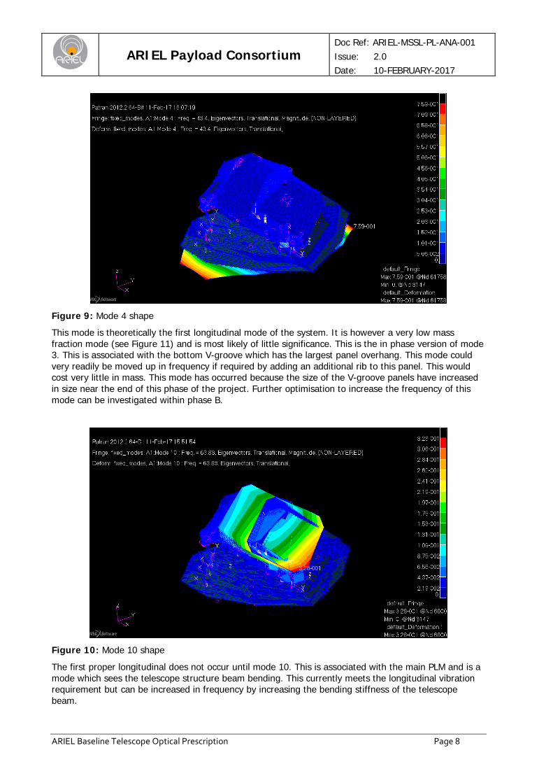
Figure 9: Mode 4 shape This mode is theoretically the first longitudinal mode of the system. It is however a very low mass fraction mode (see Figure 11) and is most likely of little significance. This is the in phase version of mode 3. This is associated with the bottom V-groove which has the largest panel overhang. This mode could very readily be moved up in frequency if required by adding an additional rib to this panel. This would cost very little in mass. This mode has occurred because the size of the V-groove panels have increased in size near the end of this phase of the project. Further optimisation to increase the frequency of this mode can be investigated within phase B.
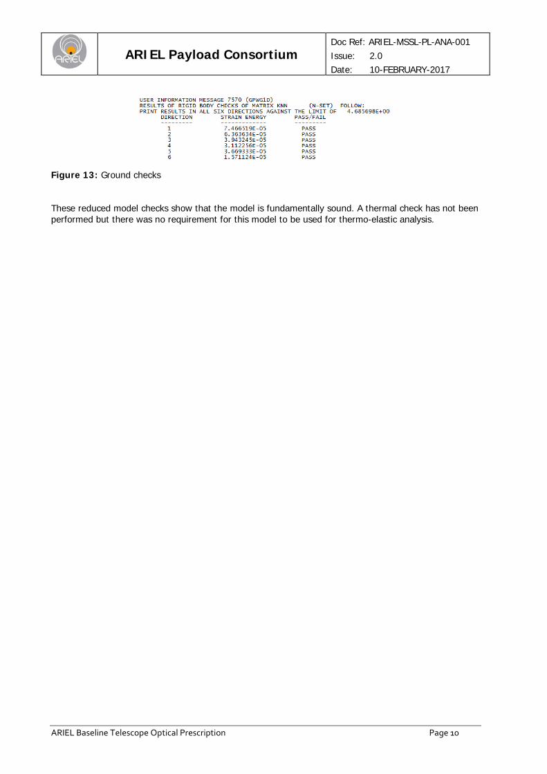
Figure 10: Mode 10 shape
The first proper longitudinal does not occur until mode 10. This is associated with the main PLM and is a mode which sees the telescope structure beam bending. This currently meets the longitudinal vibration requirement but can be increased in frequency by increasing the bending stiffness of the telescope beam.

ARIEL Payload Consortium
Doc Ref: ARIEL-MSSL-PL-ANA-001 Issue: 2.0 Date: 10-FEBRUARY-2017
ARIEL Baseline Telescope Optical Prescription Page 9
Figure 11: Modal effective mass fraction from fixed modes run
Figure 12: Modes from Free-Free run
ARIEL Payload Consortium
Doc Ref: ARIEL-MSSL-PL-ANA-001 Issue: 2.0 Date: 10-FEBRUARY-2017
ARIEL Baseline Telescope Optical Prescription Page 10
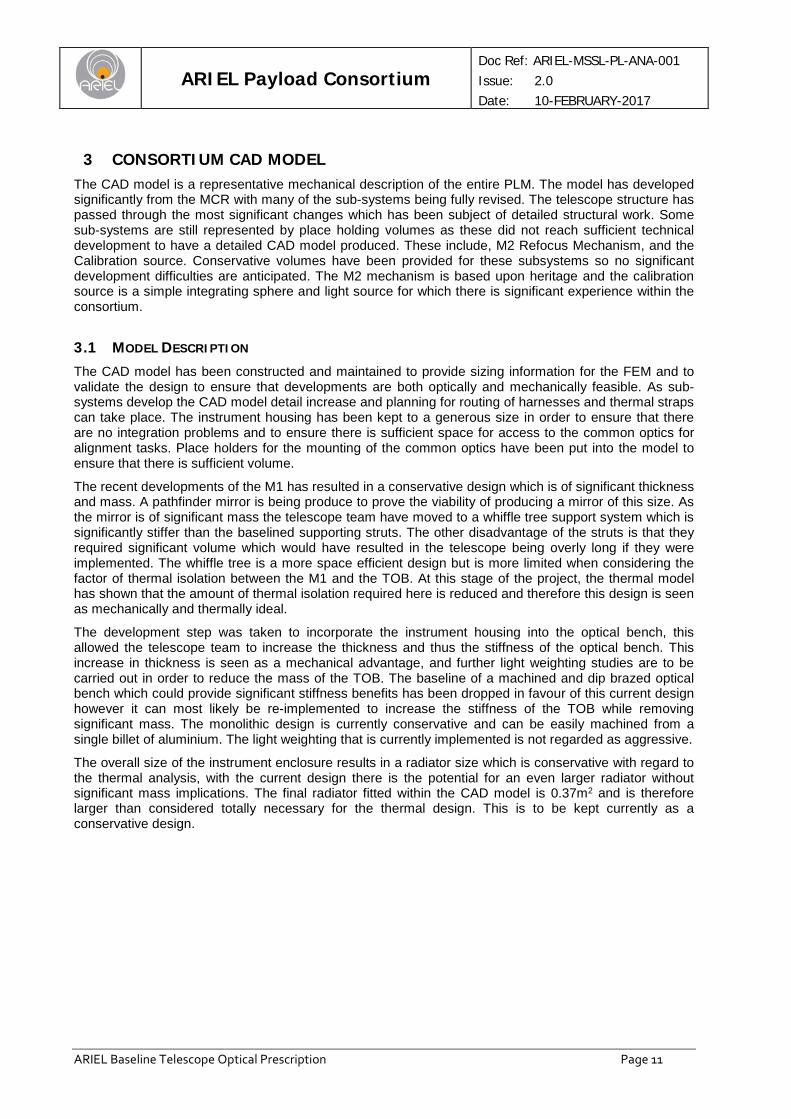
Figure 13: Ground checks
These reduced model checks show that the model is fundamentally sound. A thermal check has not been performed but there was no requirement for this model to be used for thermo-elastic analysis.
ARIEL Payload Consortium
Doc Ref: ARIEL-MSSL-PL-ANA-001 Issue: 2.0 Date: 10-FEBRUARY-2017
ARIEL Baseline Telescope Optical Prescription Page 11
3 CONSORTIUM CAD MODEL The CAD model is a representative mechanical description of the entire PLM. The model has developed significantly from the MCR with many of the sub-systems being fully revised. The telescope structure has passed through the most significant changes which has been subject of detailed structural work. Some sub-systems are still represented by place holding volumes as these did not reach sufficient technical development to have a detailed CAD model produced. These include, M2 Refocus Mechanism, and the Calibration source. Conservative volumes have been provided for these subsystems so no significant development difficulties are anticipated. The M2 mechanism is based upon heritage and the calibration source is a simple integrating sphere and light source for which there is significant experience within the consortium.
3.1 MODEL DESCRIPTION The CAD model has been constructed and maintained to provide sizing information for the FEM and to validate the design to ensure that developments are both optically and mechanically feasible. As sub-systems develop the CAD model detail increase and planning for routing of harnesses and thermal straps can take place. The instrument housing has been kept to a generous size in order to ensure that there are no integration problems and to ensure there is sufficient space for access to the common optics for alignment tasks. Place holders for the mounting of the common optics have been put into the model to ensure that there is sufficient volume.
The recent developments of the M1 has resulted in a conservative design which is of significant thickness and mass. A pathfinder mirror is being produce to prove the viability of producing a mirror of this size. As the mirror is of significant mass the telescope team have moved to a whiffle tree support system which is significantly stiffer than the baselined supporting struts. The other disadvantage of the struts is that they required significant volume which would have resulted in the telescope being overly long if they were implemented. The whiffle tree is a more space efficient design but is more limited when considering the factor of thermal isolation between the M1 and the TOB. At this stage of the project, the thermal model has shown that the amount of thermal isolation required here is reduced and therefore this design is seen as mechanically and thermally ideal.
The development step was taken to incorporate the instrument housing into the optical bench, this allowed the telescope team to increase the thickness and thus the stiffness of the optical bench. This increase in thickness is seen as a mechanical advantage, and further light weighting studies are to be carried out in order to reduce the mass of the TOB. The baseline of a machined and dip brazed optical bench which could provide significant stiffness benefits has been dropped in favour of this current design however it can most likely be re-implemented to increase the stiffness of the TOB while removing significant mass. The monolithic design is currently conservative and can be easily machined from a single billet of aluminium. The light weighting that is currently implemented is not regarded as aggressive.
The overall size of the instrument enclosure results in a radiator size which is conservative with regard to the thermal analysis, with the current design there is the potential for an even larger radiator without significant mass implications. The final radiator fitted within the CAD model is 0.37m2 and is therefore larger than considered totally necessary for the thermal design. This is to be kept currently as a conservative design.
ARIEL Payload Consortium
Doc Ref: ARIEL-MSSL-PL-ANA-001 Issue: 2.0 Date: 10-FEBRUARY-2017
ARIEL Baseline Telescope Optical Prescription Page 12
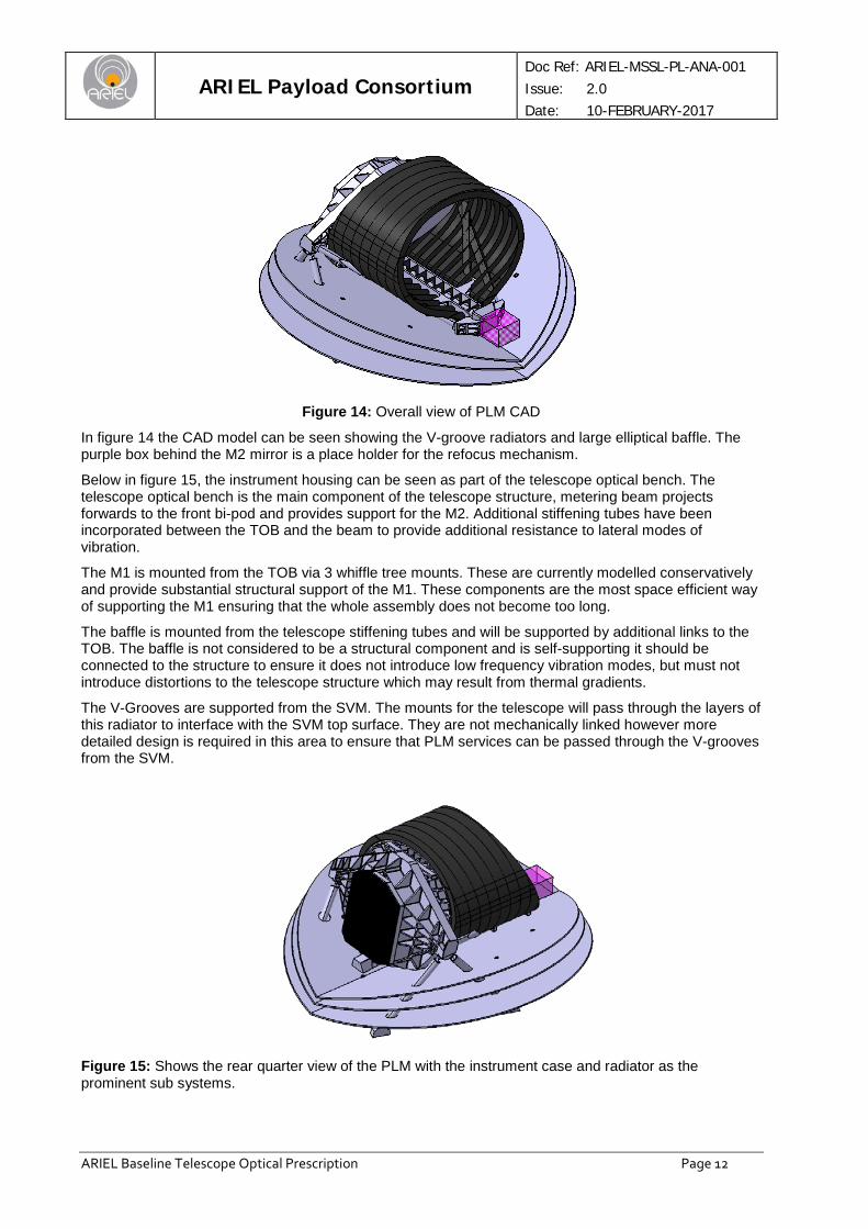
Figure 14: Overall view of PLM CAD
In figure 14 the CAD model can be seen showing the V-groove radiators and large elliptical baffle. The purple box behind the M2 mirror is a place holder for the refocus mechanism.
Below in figure 15, the instrument housing can be seen as part of the telescope optical bench. The telescope optical bench is the main component of the telescope structure, metering beam projects forwards to the front bi-pod and provides support for the M2. Additional stiffening tubes have been incorporated between the TOB and the beam to provide additional resistance to lateral modes of vibration.
The M1 is mounted from the TOB via 3 whiffle tree mounts. These are currently modelled conservatively and provide substantial structural support of the M1. These components are the most space efficient way of supporting the M1 ensuring that the whole assembly does not become too long.
The baffle is mounted from the telescope stiffening tubes and will be supported by additional links to the TOB. The baffle is not considered to be a structural component and is self-supporting it should be connected to the structure to ensure it does not introduce low frequency vibration modes, but must not introduce distortions to the telescope structure which may result from thermal gradients.
The V-Grooves are supported from the SVM. The mounts for the telescope will pass through the layers of this radiator to interface with the SVM top surface. They are not mechanically linked however more detailed design is required in this area to ensure that PLM services can be passed through the V-grooves from the SVM.
Figure 15: Shows the rear quarter view of the PLM with the instrument case and radiator as the prominent sub systems.
ARIEL Payload Consortium
Doc Ref: ARIEL-MSSL-PL-ANA-001 Issue: 2.0 Date: 10-FEBRUARY-2017
ARIEL Baseline Telescope Optical Prescription Page 13
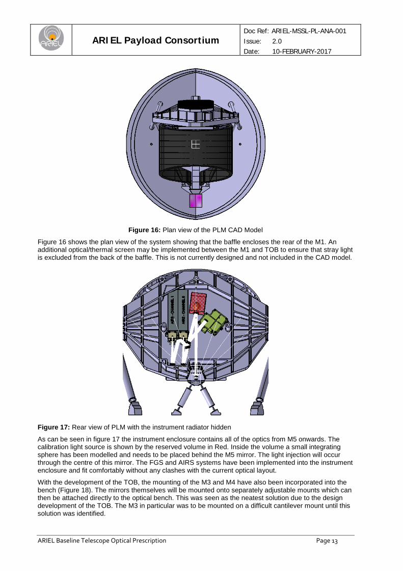
Figure 16: Plan view of the PLM CAD Model
Figure 16 shows the plan view of the system showing that the baffle encloses the rear of the M1. An additional optical/thermal screen may be implemented between the M1 and TOB to ensure that stray light is excluded from the back of the baffle. This is not currently designed and not included in the CAD model.
Figure 17: Rear view of PLM with the instrument radiator hidden
As can be seen in figure 17 the instrument enclosure contains all of the optics from M5 onwards. The calibration light source is shown by the reserved volume in Red. Inside the volume a small integrating sphere has been modelled and needs to be placed behind the M5 mirror. The light injection will occur through the centre of this mirror. The FGS and AIRS systems have been implemented into the instrument enclosure and fit comfortably without any clashes with the current optical layout.
With the development of the TOB, the mounting of the M3 and M4 have also been incorporated into the bench (Figure 18). The mirrors themselves will be mounted onto separately adjustable mounts which can then be attached directly to the optical bench. This was seen as the neatest solution due to the design development of the TOB. The M3 in particular was to be mounted on a difficult cantilever mount until this solution was identified.

ARIEL Payload Consortium
Doc Ref: ARIEL-MSSL-PL-ANA-001 Issue: 2.0 Date: 10-FEBRUARY-2017
ARIEL Baseline Telescope Optical Prescription Page 14
Mirrors and dichroics are shown with provisional mountings. These mountings are not intended to be complete designs. They are in the model as place holders and ensure that optical layout can be accommodated mechanically using relatively simple mountings.
Figure 18: Shows detail of M3 and M4 mounting incorporated into the TOB design.
Figure 19: PLM mounted onto the SVM inside the minimum allowable volume
ARIEL Payload Consortium
Doc Ref: ARIEL-MSSL-PL-ANA-001 Issue: 2.0 Date: 10-FEBRUARY-2017
ARIEL Baseline Telescope Optical Prescription Page 15
4 CONCLUSION The CAD and FEM have be developed and optimised in preparation for the MSR. Both models show that the current Ariel design is viable.
The FEM has confirmed that the overall mechanical stiffness of the system is adequate to survive the launch environment. This model carries 20% margin on all CBE and all masses are based upon detailed design estimates. V-grooves shown to be mechanically suitable for the task one very minor longitudinal mode may need to be addressed in next phase but can be easily resolved as outlined in this report.
The CAD model provides a detailed optical/mechanical layout of the PLM. This model is based upon the detailed design work of the consortium and all volumes are representative of their designs. Where systems are not designed in detail conservative volumes have been allocated based upon heritage from previous missions. The overall PLM model system fits within the volume requirements with margin. The optical design is shown to work mechanically with no physical clashes and all mountings have sufficient volume for a practical design. The telescope design has been developed for an all-aluminium structure. Mass is still to be optimised further however shown to structurally work within the requirements of the launcher.


![Welcome [ntrs.nasa.gov] · Welcome https: //ntrs.nasa.gov ... RBE3 vs RBE2 Components ... – Evaluated use of RBE3 elements Change from RBE3 to RBE2 elements had less effect than](https://img.dokumen.tips/doc/110x75/5b5e83fe7f8b9a553d8cb160/welcome-ntrsnasagov-welcome-https-ntrsnasagov-rbe3-vs-rbe2-components.jpg)