Embed Size (px)
Citation preview

ARIB STD-T53 C.S0002-C v2.0
Physical Layer Standard for cdma2000 Spread Spectrum
Systems, Revision C
Refer to "Industrial Property Rights (IPR)" in the preface of ARIB STD-T53 for Related Industrial
Property Rights. Refer to "Notice" in the preface of ARIB STD-T53 for Copyrights

Original Specification 1
This standard, ARIB-T53-C.S0002-C v2.0, was prepared by 3GPP2-WG of Association of Radio 2
Industries and Businesses (ARIB) based upon the 3GPP2 specification, C.S0002-C v2.0. 3
4
Modification to the original specification 5
None. 6
7
Notes 8
None. 9
10

3GPP2 C.S0002-C
Version 2.0
Date: July 23, 2004
Physical Layer Standard for cdma2000 Spread Spectrum Systems
Revision C
COPYRIGHT 3GPP2 and its Organizational Partners claim copyright in this document and individual Organizational Partners may copyright and issue documents or standards publications in individual Organizational Partner’s name based on this document. Requests for reproduction of this document should be directed to the 3GPP2 Secretariat at [email protected]. Requests to reproduce individual Organizational Partner’s documents should be directed to that Organizational Partner. See www.3gpp2.org for more information.

No text.

3GPP2 C.S0002-C v2.0
CONTENTS
i
FOREWORD.................................................................................................................... xliii 1
NOTES .............................................................................................................................xliv 2
REFERENCES.................................................................................................................xlvii 3
1 GENERAL......................................................................................................................1-1 4
1.1 Terms......................................................................................................................1-1 5
1.2 Numeric Information.............................................................................................1-14 6
1.2.1 Mobile Station Stored Parameters ..................................................................1-14 7
1.2.2 Base Station Parameters.................................................................................1-18 8
1.2.3 MAC Interface .................................................................................................1-19 9
1.2.3.1 Service Interfaces......................................................................................1-19 10
1.2.3.2 MAC Interface Parameters ........................................................................1-20 11
1.2.3.3 Service Interface Primitives Received by the Physical Layer.....................1-21 12
1.2.3.4 Service Interface Primitives Sent from the Physical Layer ........................1-23 13
1.3 CDMA System Time ..............................................................................................1-24 14
1.4 Tolerances.............................................................................................................1-27 15
1.5 Reserved Bits ........................................................................................................1-27 16
2 REQUIREMENTS FOR MOBILE STATION CDMA OPERATION .....................................2-1 17
2.1 Transmitter .............................................................................................................2-1 18
2.1.1 Frequency Parameters ......................................................................................2-1 19
2.1.1.1 Channel Spacing and Designation..............................................................2-1 20
2.1.1.1.1 Band Class 0 (800 MHz Band) ..............................................................2-1 21
2.1.1.1.2 Band Class 1 (1900 MHz Band) ............................................................2-5 22
2.1.1.1.3 Band Class 2 (TACS Band) ....................................................................2-9 23
2.1.1.1.4 Band Class 3 (JTACS Band) ................................................................2-13 24
2.1.1.1.5 Band Class 4 (Korean PCS Band)........................................................2-15 25
2.1.1.1.6 Band Class 5 (450 MHz Band) ............................................................2-18 26
2.1.1.1.7 Band Class 6 (2 GHz Band).................................................................2-22 27
2.1.1.1.8 Band Class 7 (700 MHz Band) ............................................................2-24 28
2.1.1.1.9 Band Class 8 (1800 MHz Band) ..........................................................2-27 29
2.1.1.1.10 Band Class 9 (900 MHz Band) ..........................................................2-29 30
2.1.1.1.11 Band Class 10 (Secondary 800 MHz Band).......................................2-31 31
2.1.1.1.12 Band Class 11 (400 MHz European PAMR Band) .............................2-35 32

3GPP2 C.S0002-C v2.0
CONTENTS
ii
2.1.1.1.13 Band Class 12 (800 MHz PAMR Band).............................................. 2-39 1
2.1.1.2 Frequency Tolerance................................................................................. 2-43 2
2.1.2 Power Output Characteristics ........................................................................ 2-43 3
2.1.2.1 Maximum Output Power........................................................................... 2-43 4
2.1.2.2 Output Power Limits................................................................................. 2-43 5
2.1.2.2.1 Minimum Controlled Output Power.................................................... 2-43 6
2.1.2.2.2 Gated Output Power ........................................................................... 2-43 7
2.1.2.2.2.1 Gated Output Power Except During a Serving Frequency PUF 8
Probe ......................................................................................................... 2-43 9
2.1.2.2.2.2 Gated Output Power During a Serving Frequency PUF Probe ...... 2-44 10
2.1.2.2.3 Standby Output Power........................................................................ 2-44 11
2.1.2.3 Controlled Output Power.......................................................................... 2-45 12
2.1.2.3.1 Estimated Open Loop Output Power................................................... 2-45 13
2.1.2.3.1.1 Open Loop Output Power When Transmitting on the Access 14
Channel..................................................................................................... 2-47 15
2.1.2.3.1.2 Open Loop Output Power When Transmitting on the Enhanced 16
Access Channel......................................................................................... 2-48 17
2.1.2.3.1.3 Open Loop Output Power When Transmitting on the Reverse 18
Common Control Channel......................................................................... 2-50 19
2.1.2.3.1.4 Open Loop Output Power When Transmitting on the Reverse 20
Traffic Channel with Radio Configuration 1 or 2....................................... 2-52 21
2.1.2.3.1.5 Open Loop Output Power When Transmitting on the Reverse 22
Traffic Channel with Radio Configuration 3, 4, 5, or 6.............................. 2-54 23
2.1.2.3.2 Closed Loop Output Power ................................................................. 2-55 24
2.1.2.3.3 Code Channel Output Power for Other than the Reverse Pilot 25
Channel........................................................................................................ 2-57 26
2.1.2.3.3.1 Code Channel Output Power for the Enhanced Access Channel 27
Header, Enhanced Access Channel Data, and Reverse Common 28
Control Channel Data ............................................................................... 2-57 29
2.1.2.3.3.2 Code Channel Output Power for the Reverse Acknowledgment 30
Channel..................................................................................................... 2-59 31
2.1.2.3.3.3 Code Channel Output Power for the Reverse Channel Quality 32
Indicator Channel ..................................................................................... 2-60 33
2.1.2.3.3.4 Code Channel Output Power for the Reverse Traffic Channel 34
with Radio Configuration 3, 4, 5, or 6 ....................................................... 2-62 35

3GPP2 C.S0002-C v2.0
CONTENTS
iii
2.1.2.4 Power Transition Characteristics ..............................................................2-69 1
2.1.2.4.1 Open Loop Estimation.........................................................................2-69 2
2.1.2.4.2 Closed Loop Correction .......................................................................2-70 3
2.1.2.4.3 Phase Continuity Requirements for Radio Configurations 3 4
through 6 .....................................................................................................2-70 5
2.1.3 Modulation Characteristics.............................................................................2-70 6
2.1.3.1 Reverse CDMA Channel Signals ...............................................................2-70 7
2.1.3.1.1 Channel Structures.............................................................................2-72 8
2.1.3.1.1.1 Spreading Rate 1...........................................................................2-73 9
2.1.3.1.1.2 Spreading Rate 3...........................................................................2-82 10
2.1.3.1.2 Modulation Parameters .......................................................................2-88 11
2.1.3.1.2.1 Spreading Rate 1...........................................................................2-88 12
2.1.3.1.2.2 Spreading Rate 3.........................................................................2-102 13
2.1.3.1.3 Data Rates.........................................................................................2-113 14
2.1.3.1.4 Forward Error Correction ..................................................................2-115 15
2.1.3.1.4.1 Convolutional Encoding ..............................................................2-117 16
2.1.3.1.4.1.1 Rate 1/4 Convolutional Code ................................................2-117 17
2.1.3.1.4.1.2 Rate 1/3 Convolutional Code ................................................2-118 18
2.1.3.1.4.1.3 Rate 1/2 Convolutional Code ................................................2-119 19
2.1.3.1.4.2 Turbo Encoding...........................................................................2-119 20
2.1.3.1.4.2.1 Rate 1/2, 1/3, 1/4, and 1/5 Turbo Encoders .......................2-120 21
2.1.3.1.4.2.2 Turbo Code Termination........................................................2-122 22
2.1.3.1.4.2.3 Turbo Interleavers .................................................................2-123 23
2.1.3.1.4.3 Block Encoding ...........................................................................2-127 24
2.1.3.1.5 Code Symbol Repetition....................................................................2-127 25
2.1.3.1.6 Puncturing ........................................................................................2-130 26
2.1.3.1.6.1 Convolutional Code Symbol Puncturing .....................................2-130 27
2.1.3.1.6.2 Turbo Code Symbol Puncturing ..................................................2-130 28
2.1.3.1.6.3 Flexible and Variable Rate Puncturing........................................2-131 29
2.1.3.1.7 Block Interleaving .............................................................................2-132 30
2.1.3.1.7.1 Interleaving for the Reverse Traffic Channel with Radio 31
Configurations 1 and 2............................................................................2-132 32

3GPP2 C.S0002-C v2.0
CONTENTS
iv
2.1.3.1.7.2 Bit-Reversal Interleaving............................................................. 2-132 1
2.1.3.1.8 Orthogonal Modulation and Spreading............................................. 2-133 2
2.1.3.1.8.1 Orthogonal Modulation............................................................... 2-133 3
2.1.3.1.8.2 Orthogonal Spreading................................................................. 2-136 4
2.1.3.1.9 Gated Transmission.......................................................................... 2-139 5
2.1.3.1.9.1 Rates and Gating for Radio Configurations 1 and 2.................... 2-139 6
2.1.3.1.9.2 Data Burst Randomizing Algorithm for Radio Configurations 1 7
and 2 ....................................................................................................... 2-142 8
2.1.3.1.9.3 Gating During a PUF Probe......................................................... 2-143 9
2.1.3.1.9.4 Reverse Pilot Channel Gating ..................................................... 2-143 10
2.1.3.1.9.5 Enhanced Access Channel Preamble Gating .............................. 2-144 11
2.1.3.1.9.6 Reverse Common Control Channel Preamble Gating.................. 2-144 12
2.1.3.1.9.7 Reverse Channel Quality Indicator Channel Gating................... 2-144 13
2.1.3.1.9.8 Reverse Fundamental Channel Gating ....................................... 2-144 14
2.1.3.1.10 Reverse Power Control Subchannel................................................ 2-144 15
2.1.3.1.10.1 Reverse Power Control Subchannel Structure.......................... 2-145 16
2.1.3.1.10.2 Outer Power Control Loop......................................................... 2-150 17
2.1.3.1.10.3 Inner Power Control Loop ......................................................... 2-152 18
2.1.3.1.11 Direct Sequence Spreading............................................................. 2-152 19
2.1.3.1.12 Quadrature Spreading .................................................................... 2-155 20
2.1.3.1.12.1 Spreading Rate 1....................................................................... 2-161 21
2.1.3.1.12.2 Spreading Rate 3....................................................................... 2-161 22
2.1.3.1.13 Baseband Filtering.......................................................................... 2-162 23
2.1.3.1.13.1 Spreading Rate 1....................................................................... 2-162 24
2.1.3.1.13.2 Spreading Rate 3....................................................................... 2-164 25
2.1.3.1.14 Carrier Phase Offset for Radio Configurations 1 and 2 ................... 2-167 26
2.1.3.2 Reverse Pilot Channel............................................................................. 2-167 27
2.1.3.2.1 Reverse Power Control Subchannel.................................................. 2-168 28
2.1.3.2.2 Reverse Pilot Channel Spreading...................................................... 2-168 29
2.1.3.2.3 Reverse Pilot Channel Gating ........................................................... 2-168 30
2.1.3.2.4 Reverse Pilot Channel Operation during Reverse Traffic Channel 31
Preamble .................................................................................................... 2-171 32

3GPP2 C.S0002-C v2.0
CONTENTS
v
2.1.3.2.5 Reverse Pilot Channel Quadrature Spreading ..................................2-172 1
2.1.3.2.6 Reverse Pilot Channel Baseband Filtering ........................................2-172 2
2.1.3.2.7 Reverse Pilot Channel Transmission Processing...............................2-172 3
2.1.3.3 Access Channel.......................................................................................2-172 4
2.1.3.3.1 Access Channel Time Alignment and Modulation Rate ....................2-172 5
2.1.3.3.2 Access Channel Frame Structure .....................................................2-173 6
2.1.3.3.2.1 Access Channel Preamble ...........................................................2-173 7
2.1.3.3.3 Access Channel Convolutional Encoding..........................................2-173 8
2.1.3.3.4 Access Channel Code Symbol Repetition..........................................2-174 9
2.1.3.3.5 Access Channel Interleaving.............................................................2-174 10
2.1.3.3.6 Access Channel Modulation..............................................................2-174 11
2.1.3.3.7 Access Channel Gating .....................................................................2-174 12
2.1.3.3.8 Access Channel Direct Sequence Spreading.....................................2-174 13
2.1.3.3.9 Access Channel Quadrature Spreading ............................................2-174 14
2.1.3.3.10 Access Channel Baseband Filtering................................................2-174 15
2.1.3.3.11 Access Channel Transmission Processing ......................................2-174 16
2.1.3.4 Enhanced Access Channel......................................................................2-174 17
2.1.3.4.1 Enhanced Access Channel Time Alignment and Modulation Rate ...2-175 18
2.1.3.4.2 Enhanced Access Channel Frame Structure ....................................2-176 19
2.1.3.4.2.1 Enhanced Access Channel Frame Quality Indicator...................2-177 20
2.1.3.4.2.2 Enhanced Access Channel Encoder Tail Bits..............................2-178 21
2.1.3.4.2.3 Enhanced Access Channel Preamble ..........................................2-178 22
2.1.3.4.3 Enhanced Access Channel Convolutional Encoding.........................2-180 23
2.1.3.4.4 Enhanced Access Channel Code Symbol Repetition.........................2-180 24
2.1.3.4.5 Enhanced Access Channel Interleaving............................................2-180 25
2.1.3.4.6 Enhanced Access Channel Modulation and Orthogonal Spreading..2-181 26
2.1.3.4.7 Enhanced Access Channel Quadrature Spreading ...........................2-181 27
2.1.3.4.8 Enhanced Access Channel Baseband Filtering.................................2-181 28
2.1.3.4.9 Enhanced Access Channel Transmission Processing .......................2-181 29
2.1.3.5 Reverse Common Control Channel .........................................................2-182 30
2.1.3.5.1 Reverse Common Control Channel Time Alignment and 31
Modulation Rate .........................................................................................2-182 32
3GPP2 C.S0002-C v2.0
CONTENTS
vi
2.1.3.5.2 Reverse Common Control Channel Frame Structure ....................... 2-183 1
2.1.3.5.2.1 Reverse Common Control Channel Frame Quality Indicator...... 2-184 2
2.1.3.5.2.2 Reverse Common Control Channel Encoder Tail Bits................. 2-185 3
2.1.3.5.2.3 Reverse Common Control Channel Preamble ............................. 2-185 4
2.1.3.5.2.4 Reverse Common Control Channel Data .................................... 2-186 5
2.1.3.5.3 Reverse Common Control Channel Convolutional Encoding............ 2-186 6
2.1.3.5.4 Reverse Common Control Channel Code Symbol Repetition............ 2-186 7
2.1.3.5.5 Reverse Common Control Channel Interleaving............................... 2-186 8
2.1.3.5.6 Reverse Common Control Channel Modulation and Orthogonal 9
Spreading................................................................................................... 2-187 10
2.1.3.5.7 Reverse Common Control Channel Quadrature Spreading .............. 2-187 11
2.1.3.5.8 Reverse Common Control Channel Baseband Filtering.................... 2-187 12
2.1.3.5.9 Reverse Common Control Channel Transmission Processing .......... 2-187 13
2.1.3.6 Reverse Dedicated Control Channel ....................................................... 2-187 14
2.1.3.6.1 Reverse Dedicated Control Channel Time Alignment and 15
Modulation Rates ....................................................................................... 2-187 16
2.1.3.6.2 Reverse Dedicated Control Channel Frame Structure...................... 2-188 17
2.1.3.6.2.1 Reverse Dedicated Control Channel Frame Quality Indicator .... 2-189 18
2.1.3.6.2.2 Reverse Dedicated Control Channel Encoder Tail Bits ............... 2-191 19
2.1.3.6.2.3 Reverse Traffic Channel Preamble .............................................. 2-191 20
2.1.3.6.3 Reverse Dedicated Control Channel Convolutional Encoding .......... 2-191 21
2.1.3.6.4 Reverse Dedicated Control Channel Code Symbol Repetition .......... 2-191 22
2.1.3.6.5 Reverse Dedicated Control Channel Code Symbol Puncturing......... 2-191 23
2.1.3.6.6 Reverse Dedicated Control Channel Interleaving ............................. 2-191 24
2.1.3.6.7 Reverse Dedicated Control Channel Modulation and Orthogonal 25
Spreading................................................................................................... 2-191 26
2.1.3.6.8 Reverse Dedicated Control Channel Quadrature Spreading............. 2-191 27
2.1.3.6.9 Reverse Dedicated Control Channel Baseband Filtering .................. 2-191 28
2.1.3.6.10 Reverse Dedicated Control Channel Transmission Processing....... 2-191 29
2.1.3.7 Reverse Acknowledgment Channel......................................................... 2-192 30
2.1.3.7.1 Reverse Acknowledgment Channel Structure and Time Alignment . 2-192 31
2.1.3.7.2 Reverse Acknowledgment Channel Modulation................................ 2-192 32
2.1.3.7.3 Reverse Acknowledgment Channel Quadrature Spreading .............. 2-192 33

3GPP2 C.S0002-C v2.0
CONTENTS
vii
2.1.3.7.4 Reverse Acknowledgment Channel Baseband Filtering....................2-192 1
2.1.3.7.5 Reverse Acknowledgment Channel Transmission Processing...........2-192 2
2.1.3.8 Reverse Channel Quality Indicator Channel...........................................2-193 3
2.1.3.8.1 Reverse Channel Quality Indicator Channel Structure ....................2-194 4
2.1.3.8.2 Reverse Channel Quality Indicator Channel Modulation..................2-195 5
2.1.3.8.3 Reverse Channel Quality Indicator Channel Gating .........................2-195 6
2.1.3.8.4 Reverse Channel Quality Indicator Channel Quadrature Spreading 2-195 7
2.1.3.8.5 Reverse Channel Quality Indicator Channel Baseband Filtering......2-195 8
2.1.3.8.6 Reverse Channel Quality Indicator Channel Transmission 9
Processing ..................................................................................................2-195 10
2.1.3.9 Reverse Fundamental Channel...............................................................2-195 11
2.1.3.9.1 Reverse Fundamental Channel Time Alignment and Modulation 12
Rates ..........................................................................................................2-195 13
2.1.3.9.2 Reverse Fundamental Channel Frame Structure .............................2-196 14
2.1.3.9.2.1 Reverse Fundamental Channel Frame Quality Indicator............2-199 15
2.1.3.9.2.2 Reverse Fundamental Channel Encoder Tail Bits.......................2-202 16
2.1.3.9.2.3 Reverse Traffic Channel Preambles.............................................2-202 17
2.1.3.9.2.3.1 Radio Configurations 1 and 2................................................2-203 18
2.1.3.9.2.3.2 Radio Configurations 3 through 6.........................................2-203 19
2.1.3.9.3 Reverse Fundamental Channel Convolutional Encoding..................2-203 20
2.1.3.9.4 Reverse Fundamental Channel Code Symbol Repetition..................2-203 21
2.1.3.9.5 Reverse Fundamental Channel Code Symbol Puncturing ................2-203 22
2.1.3.9.6 Reverse Fundamental Channel Interleaving.....................................2-203 23
2.1.3.9.7 Reverse Fundamental Channel Modulation and Orthogonal 24
Spreading ...................................................................................................2-203 25
2.1.3.9.8 Reverse Fundamental Channel Gating .............................................2-203 26
2.1.3.9.9 Reverse Fundamental Channel Direct Sequence Spreading.............2-204 27
2.1.3.9.10 Reverse Fundamental Channel Quadrature Spreading ..................2-204 28
2.1.3.9.11 Reverse Fundamental Channel Baseband Filtering........................2-204 29
2.1.3.9.12 Reverse Fundamental Channel Transmission Processing ..............2-205 30
2.1.3.10 Reverse Supplemental Channel............................................................2-205 31
2.1.3.10.1 Reverse Supplemental Channel Time Alignment and Modulation 32
Rates ..........................................................................................................2-205 33

3GPP2 C.S0002-C v2.0
CONTENTS
viii
2.1.3.10.2 Reverse Supplemental Channel Frame Structure .......................... 2-208 1
2.1.3.10.2.1 Reverse Supplemental Channel Frame Quality Indicator......... 2-217 2
2.1.3.10.2.2 Reverse Supplemental Channel Encoder Tail Bits.................... 2-219 3
2.1.3.10.3 Reverse Supplemental Channel Forward Error Correction 4
Encoding .................................................................................................... 2-220 5
2.1.3.10.4 Reverse Supplemental Channel Code Symbol Repetition............... 2-220 6
2.1.3.10.5 Reverse Supplemental Channel Code Symbol Puncturing ............. 2-220 7
2.1.3.10.6 Reverse Supplemental Channel Interleaving.................................. 2-220 8
2.1.3.10.7 Reverse Supplemental Channel Modulation and Orthogonal 9
Spreading................................................................................................... 2-220 10
2.1.3.10.8 Reverse Supplemental Channel Quadrature Spreading ................. 2-220 11
2.1.3.10.9 Reverse Supplemental Channel Baseband Filtering....................... 2-220 12
2.1.3.10.10 Reverse Supplemental Channel Transmission Processing ........... 2-220 13
2.1.3.11 Reverse Supplemental Code Channel................................................... 2-220 14
2.1.3.11.1 Reverse Supplemental Code Channel Time Alignment and 15
Modulation Rates ....................................................................................... 2-221 16
2.1.3.11.2 Reverse Supplemental Code Channel Frame Structure ................. 2-221 17
2.1.3.11.2.1 Reverse Supplemental Code Channel Frame Quality Indicator 2-222 18
2.1.3.11.2.2 Reverse Supplemental Code Channel Encoder Tail Bits........... 2-223 19
2.1.3.11.2.3 Reverse Supplemental Code Channel Preambles ..................... 2-223 20
2.1.3.11.2.3.1 Reverse Supplemental Code Channel Preamble ................. 2-223 21
2.1.3.11.2.3.2 Reverse Supplemental Code Channel Discontinuous 22
Transmission Preamble ........................................................................ 2-223 23
2.1.3.11.3 Reverse Supplemental Code Channel Convolutional Encoding...... 2-223 24
2.1.3.11.4 Reverse Supplemental Code Channel Code Symbol Repetition...... 2-224 25
2.1.3.11.5 Reverse Supplemental Code Channel Interleaving......................... 2-224 26
2.1.3.11.6 Reverse Supplemental Code Channel Modulation.......................... 2-224 27
2.1.3.11.7 Reverse Supplemental Code Channel Direct Sequence Spreading.2-224 28
2.1.3.11.8 Reverse Supplemental Code Channel Quadrature Spreading ........ 2-224 29
2.1.3.11.9 Reverse Supplemental Code Channel Baseband Filtering.............. 2-224 30
2.1.3.11.10 Reverse Supplemental Code Channel Transmission Processing .. 2-224 31
2.1.4 Limitations on Emissions ............................................................................. 2-224 32
2.1.4.1 Conducted Spurious Emissions ............................................................. 2-224 33

3GPP2 C.S0002-C v2.0
CONTENTS
ix
2.1.4.2 Radiated Spurious Emissions .................................................................2-225 1
2.1.5 Synchronization and Timing .........................................................................2-225 2
2.1.5.1 Pilot to Walsh Cover Time Tolerance.......................................................2-226 3
2.1.5.2 Pilot to Walsh Cover Phase Tolerance .....................................................2-226 4
2.1.6 Transmitter Performance Requirements .......................................................2-226 5
2.2 Receiver ..............................................................................................................2-226 6
2.2.1 Channel Spacing and Designation................................................................2-226 7
2.2.2 Demodulation Characteristics ......................................................................2-226 8
2.2.2.1 Processing...............................................................................................2-226 9
2.2.2.2 Erasure Indicator Bit and Quality Indicator Bit......................................2-227 10
2.2.2.3 Forward Traffic Channel Time Alignment ...............................................2-230 11
2.2.2.4 Interface to the MAC Layer .....................................................................2-230 12
2.2.2.4.1 Sync Channel Reception Processing .................................................2-230 13
2.2.2.4.2 Paging Channel Reception Processing ..............................................2-230 14
2.2.2.4.3 Broadcast Control Channel Reception Processing ............................2-230 15
2.2.2.4.4 Quick Paging Channel Reception Processing....................................2-231 16
2.2.2.4.5 Common Power Control Channel Reception Processing ...................2-231 17
2.2.2.4.6 Common Assignment Channel Reception Processing.......................2-231 18
2.2.2.4.7 Forward Common Control Channel Reception Processing................2-231 19
2.2.2.4.8 Forward Packet Data Control Channel Reception Processing...........2-231 20
2.2.2.4.8.1 8-bit Frame Quality Indicator Calculation ..................................2-232 21
2.2.2.4.9 Forward Dedicated Control Channel Reception Processing..............2-233 22
2.2.2.4.10 Forward Fundamental Channel Reception Processing ...................2-234 23
2.2.2.4.11 Forward Supplemental Channel Reception Processing...................2-234 24
2.2.2.4.12 Forward Supplemental Code Channel Reception Processing..........2-234 25
2.2.2.4.13 Forward Packet Data Channel Reception Processing......................2-234 26
2.2.3 Limitations on Emissions..............................................................................2-235 27
2.2.4 Receiver Performance Requirements ............................................................2-235 28
2.3 Malfunction Detection ........................................................................................2-235 29
2.3.1 Malfunction Timer.........................................................................................2-235 30
2.3.2 False Transmission .......................................................................................2-235 31
3 REQUIREMENTS FOR BASE STATION CDMA OPERATION .........................................3-1 32

3GPP2 C.S0002-C v2.0
CONTENTS
x
3.1 Transmitter............................................................................................................. 3-1 1
3.1.1 Frequency Parameters ...................................................................................... 3-1 2
3.1.1.1 Channel Spacing and Designation ............................................................. 3-1 3
3.1.1.1.1 Band Class 0 (800 MHz Band) .............................................................. 3-1 4
3.1.1.1.2 Band Class 1 (1900 MHz Band) ............................................................ 3-1 5
3.1.1.1.3 Band Class 2 (TACS Band).................................................................... 3-1 6
3.1.1.1.4 Band Class 3 (JTACS Band).................................................................. 3-2 7
3.1.1.1.5 Band Class 4 (Korean PCS Band).......................................................... 3-2 8
3.1.1.1.6 Band Class 5 (450 MHz Band) .............................................................. 3-2 9
3.1.1.1.7 Band Class 6 (2 GHz Band)................................................................... 3-2 10
3.1.1.1.8 Band Class 7 (700 MHz Band) .............................................................. 3-2 11
3.1.1.1.9 Band Class 8 (1800 MHz Band) ............................................................ 3-3 12
3.1.1.1.10 Band Class 9 (900 MHz Band) ............................................................ 3-3 13
3.1.1.1.11 Band Class 10 (Secondary 800 MHz Band)......................................... 3-3 14
3.1.1.1.12 Band Class 11 (400 MHz European PAMR Band) ............................... 3-3 15
3.1.1.1.13 Band Class 12 (800 MHz European PAMR Band) ............................... 3-4 16
3.1.1.2 Frequency Tolerance................................................................................... 3-4 17
3.1.2 Power Output Characteristics .......................................................................... 3-4 18
3.1.3 Modulation Characteristics .............................................................................. 3-4 19
3.1.3.1 Forward CDMA Channel Signals ................................................................ 3-4 20
3.1.3.1.1 Channel Structures .............................................................................. 3-7 21
3.1.3.1.1.1 Spreading Rate 1............................................................................. 3-8 22
3.1.3.1.1.2 Spreading Rate 3........................................................................... 3-26 23
3.1.3.1.2 Modulation Parameters....................................................................... 3-42 24
3.1.3.1.2.1 Spreading Rate 1........................................................................... 3-42 25
3.1.3.1.2.2 Spreading Rate 3........................................................................... 3-61 26
3.1.3.1.3 Data Rates .......................................................................................... 3-80 27
3.1.3.1.4 Forward Error Correction.................................................................... 3-84 28
3.1.3.1.4.1 Convolutional Encoding................................................................ 3-87 29
3.1.3.1.4.1.1 Rate 1/6 Convolutional Code.................................................. 3-87 30
3.1.3.1.4.1.2 Rate 1/4 Convolutional Code.................................................. 3-88 31
3.1.3.1.4.1.3 Rate 1/3 Convolutional Code.................................................. 3-89 32

3GPP2 C.S0002-C v2.0
CONTENTS
xi
3.1.3.1.4.1.4 Rate 1/2 Convolutional Code ..................................................3-90 1
3.1.3.1.4.2 Turbo Encoding.............................................................................3-91 2
3.1.3.1.4.2.1 Rate 1/2, 1/3, 1/4, and 1/5 Turbo Encoders .........................3-91 3
3.1.3.1.4.2.2 Turbo Code Termination..........................................................3-94 4
3.1.3.1.4.2.3 Turbo Interleavers ...................................................................3-96 5
3.1.3.1.5 Code Symbol Repetition......................................................................3-99 6
3.1.3.1.6 Puncturing ........................................................................................3-101 7
3.1.3.1.6.1 Convolutional Code Symbol Puncturing .....................................3-101 8
3.1.3.1.6.2 Turbo Code Symbol Puncturing ..................................................3-101 9
3.1.3.1.6.3 Flexible and Variable Rate Puncturing........................................3-102 10
3.1.3.1.6.4 Forward Packet Data Control Channel Puncturing.....................3-103 11
3.1.3.1.7 Block Interleaving .............................................................................3-103 12
3.1.3.1.7.1 Spreading Rate 1 Interleaving.....................................................3-105 13
3.1.3.1.7.1.1 Bit-Reversal Order Interleaver...............................................3-105 14
3.1.3.1.7.1.2 Forward-Backwards Bit-Reversal Order Interleaver..............3-105 15
3.1.3.1.7.1.3 Interleaving for the Forward Packet Data Channel ...............3-106 16
3.1.3.1.7.1.3.1 Symbol Separation ..........................................................3-106 17
3.1.3.1.7.1.3.2 Subblock Interleaving .....................................................3-106 18
3.1.3.1.7.1.3.3 Symbol Grouping.............................................................3-107 19
3.1.3.1.7.2 Spreading Rate 3 Interleaving.....................................................3-108 20
3.1.3.1.8 Sequence Repetition .........................................................................3-108 21
3.1.3.1.9 Data Scrambling ...............................................................................3-109 22
3.1.3.1.10 Data Scrambling for the Forward Packet Data Channel .................3-110 23
3.1.3.1.11 Forward Power Control Subchannel ...............................................3-110 24
3.1.3.1.12 Subpacket Symbol Selection for the Forward Packet Data 25
Channel......................................................................................................3-115 26
3.1.3.1.13 Modulation for the Forward Packet Data Channel..........................3-115 27
3.1.3.1.13.1 QPSK Modulation......................................................................3-115 28
3.1.3.1.13.2 8-PSK Modulation .....................................................................3-116 29
3.1.3.1.13.3 16-QAM Modulation..................................................................3-117 30
3.1.3.1.13.4 Modulation Order......................................................................3-119 31
3.1.3.1.14 Symbol Demultiplexing and Repetition...........................................3-124 32

3GPP2 C.S0002-C v2.0
CONTENTS
xii
3.1.3.1.14.1 Spreading Rate 1 Symbol Demultiplexing ................................ 3-124 1
3.1.3.1.14.2 Spreading Rate 1 Symbol Repetition for Transmit Diversity ..... 3-125 2
3.1.3.1.14.3 Spreading Rate 3 Symbol Demultiplexing ................................ 3-125 3
3.1.3.1.14.4 Symbol Demultiplexing and Walsh Channel Processing for 4
the Forward Packet Data Channel .......................................................... 3-126 5
3.1.3.1.15 Orthogonal and Quasi-Orthogonal Spreading ................................ 3-126 6
3.1.3.1.16 Quadrature Spreading .................................................................... 3-131 7
3.1.3.1.17 Filtering .......................................................................................... 3-132 8
3.1.3.1.17.1 Baseband Filtering.................................................................... 3-132 9
3.1.3.1.17.2 Phase Characteristics ............................................................... 3-134 10
3.1.3.2 Pilot Channels ........................................................................................ 3-135 11
3.1.3.2.1 Pilot PN Sequence Offset................................................................... 3-135 12
3.1.3.2.2 Pilot Channel Orthogonal and Quasi-Orthogonal Spreading............ 3-136 13
3.1.3.2.2.1 Forward Pilot Channel ................................................................ 3-136 14
3.1.3.2.2.2 Forward Transmit Diversity Pilot Channel.................................. 3-137 15
3.1.3.2.2.3 Auxiliary Pilot Channel ............................................................... 3-138 16
3.1.3.2.2.4 Auxiliary Transmit Diversity Pilot Channel................................. 3-138 17
3.1.3.2.3 Pilot Channel Quadrature Spreading................................................ 3-139 18
3.1.3.2.4 Pilot Channel Filtering...................................................................... 3-139 19
3.1.3.2.5 Hopping Pilot Beacon Timing............................................................ 3-139 20
3.1.3.3 Sync Channel ......................................................................................... 3-139 21
3.1.3.3.1 Sync Channel Time Alignment and Modulation Rates...................... 3-139 22
3.1.3.3.2 Sync Channel Structure ................................................................... 3-140 23
3.1.3.3.3 Sync Channel Convolutional Encoding ............................................ 3-140 24
3.1.3.3.4 Sync Channel Code Symbol Repetition ............................................ 3-140 25
3.1.3.3.5 Sync Channel Interleaving................................................................ 3-140 26
3.1.3.3.6 Sync Channel Orthogonal Spreading................................................ 3-140 27
3.1.3.3.7 Sync Channel Quadrature Spreading............................................... 3-140 28
3.1.3.3.8 Sync Channel Filtering ..................................................................... 3-140 29
3.1.3.3.9 Sync Channel Transmission Processing ........................................... 3-141 30
3.1.3.4 Paging Channel....................................................................................... 3-141 31
3.1.3.4.1 Paging Channel Time Alignment and Modulation Rates................... 3-141 32
3GPP2 C.S0002-C v2.0
CONTENTS
xiii
3.1.3.4.2 Paging Channel Structure.................................................................3-141 1
3.1.3.4.3 Paging Channel Convolutional Encoding..........................................3-141 2
3.1.3.4.4 Paging Channel Code Symbol Repetition..........................................3-141 3
3.1.3.4.5 Paging Channel Interleaving .............................................................3-141 4
3.1.3.4.6 Paging Channel Data Scrambling .....................................................3-142 5
3.1.3.4.7 Paging Channel Orthogonal Spreading .............................................3-142 6
3.1.3.4.8 Paging Channel Quadrature Spreading ............................................3-142 7
3.1.3.4.9 Paging Channel Filtering...................................................................3-142 8
3.1.3.4.10 Paging Channel Transmission Processing.......................................3-142 9
3.1.3.5 Broadcast Control Channel.....................................................................3-142 10
3.1.3.5.1 Broadcast Control Channel Time Alignment and Modulation Rates.3-143 11
3.1.3.5.2 Broadcast Control Channel Structure ..............................................3-143 12
3.1.3.5.2.1 Broadcast Control Channel Frame Quality Indicator..................3-143 13
3.1.3.5.2.2 Broadcast Control Channel Encoder Tail Bits.............................3-144 14
3.1.3.5.3 Broadcast Control Channel Convolutional Encoding........................3-144 15
3.1.3.5.4 Broadcast Control Channel Interleaving...........................................3-144 16
3.1.3.5.5 Broadcast Control Channel Sequence Repetition .............................3-145 17
3.1.3.5.6 Broadcast Control Channel Data Scrambling ...................................3-145 18
3.1.3.5.7 Broadcast Control Channel Orthogonal Spreading...........................3-145 19
3.1.3.5.8 Broadcast Control Channel Quadrature Spreading ..........................3-145 20
3.1.3.5.9 Broadcast Control Channel Filtering ................................................3-145 21
3.1.3.5.10 Broadcast Control Channel Transmission Processing ....................3-145 22
3.1.3.6 Quick Paging Channel ............................................................................3-145 23
3.1.3.6.1 Quick Paging Channel Time Alignment and Modulation Rates ........3-146 24
3.1.3.6.2 Quick Paging Channel Structure ......................................................3-146 25
3.1.3.6.3 Quick Paging Channel Paging Indicator Enabling ............................3-146 26
3.1.3.6.4 Quick Paging Channel Configuration Change Indicator Enabling ....3-146 27
3.1.3.6.5 Quick Paging Channel Broadcast Indicator Enabling .......................3-147 28
3.1.3.6.6 Quick Paging Channel Paging Indicator, Configuration Change 29
Indicator, and Broadcast Indicator Repetition ...........................................3-147 30
3.1.3.6.7 Quick Paging Channel Spreading .....................................................3-147 31
3.1.3.6.8 Quick Paging Channel Quadrature Spreading..................................3-147 32

3GPP2 C.S0002-C v2.0
CONTENTS
xiv
3.1.3.6.9 Quick Paging Channel Filtering........................................................ 3-147 1
3.1.3.6.10 Quick Paging Channel Transmit Power Level ................................. 3-147 2
3.1.3.6.11 Quick Paging Channel Transmission Processing............................ 3-148 3
3.1.3.7 Common Power Control Channel............................................................ 3-148 4
3.1.3.7.1 Common Power Control Channel Time Alignment and Modulation 5
Rates .......................................................................................................... 3-148 6
3.1.3.7.2 Common Power Control Channel Structure ..................................... 3-149 7
3.1.3.7.3 Pseudo-Randomization of Power Control Bit Positions..................... 3-150 8
3.1.3.7.4 Common Power Control Channel Orthogonal Spreading.................. 3-151 9
3.1.3.7.5 Common Power Control Channel Quadrature Spreading ................. 3-151 10
3.1.3.7.6 Common Power Control Channel Filtering ....................................... 3-151 11
3.1.3.7.7 Common Power Control Channel Transmission Processing ............. 3-151 12
3.1.3.8 Common Assignment Channel ............................................................... 3-152 13
3.1.3.8.1 Common Assignment Channel Time Alignment and Modulation 14
Rates .......................................................................................................... 3-152 15
3.1.3.8.2 Common Assignment Channel Structure ......................................... 3-152 16
3.1.3.8.2.1 Common Assignment Channel Frame Quality Indicator ............ 3-153 17
3.1.3.8.2.2 Common Assignment Channel Encoder Tail Bits ....................... 3-154 18
3.1.3.8.3 Common Assignment Channel Convolutional Encoding .................. 3-154 19
3.1.3.8.4 Common Assignment Channel Interleaving ..................................... 3-154 20
3.1.3.8.5 Common Assignment Channel Data Scrambling.............................. 3-154 21
3.1.3.8.6 Common Assignment Channel Orthogonal Spreading ..................... 3-154 22
3.1.3.8.7 Common Assignment Channel Quadrature Spreading..................... 3-154 23
3.1.3.8.8 Common Assignment Channel Filtering ........................................... 3-154 24
3.1.3.8.9 Common Assignment Channel Transmission Processing ................. 3-154 25
3.1.3.9 Forward Common Control Channel ........................................................ 3-155 26
3.1.3.9.1 Forward Common Control Channel Time Alignment and 27
Modulation Rates ....................................................................................... 3-155 28
3.1.3.9.2 Forward Common Control Channel Structure.................................. 3-155 29
3.1.3.9.2.1 Forward Common Control Channel Frame Quality Indicator ..... 3-156 30
3.1.3.9.2.2 Forward Common Control Channel Encoder Tail Bits ................ 3-157 31
3.1.3.9.3 Forward Common Control Channel Encoding .................................. 3-157 32
3.1.3.9.4 Forward Common Control Channel Interleaving .............................. 3-158 33

3GPP2 C.S0002-C v2.0
CONTENTS
xv
3.1.3.9.5 Forward Common Control Channel Data Scrambling.......................3-158 1
3.1.3.9.6 Forward Common Control Channel Orthogonal Spreading. .............3-158 2
3.1.3.9.7 Forward Common Control Channel Quadrature Spreading..............3-158 3
3.1.3.9.8 Forward Common Control Channel Filtering ....................................3-158 4
3.1.3.9.9 Forward Common Control Channel Transmission Processing ..........3-158 5
3.1.3.10 Forward Packet Data Control Channel .................................................3-158 6
3.1.3.10.1 Forward Packet Data Control Channel Time Alignment, and 7
Modulation Rates .......................................................................................3-159 8
3.1.3.10.2 Forward Packet Data Control Channel Frame Structure ................3-159 9
3.1.3.10.2.1 Forward Packet Data Control Channel Scrambling...................3-160 10
3.1.3.10.2.2 Frame Quality Indicator-Covered SDU[0…7] for the Forward 11
Packet Data Control Channel ..................................................................3-160 12
3.1.3.10.2.3 Forward Packet Data Control Channel Inner Frame Quality 13
Indicator ..................................................................................................3-161 14
3.1.3.10.3 Forward Packet Data Control Channel Encoder Tail Bits ...............3-162 15
3.1.3.10.4 Forward Packet Data Control Channel Convolutional Encoding ....3-162 16
3.1.3.10.5 Forward Packet Data Control Channel Code Symbol Repetition ....3-162 17
3.1.3.10.6 Forward Packet Data Control Channel Puncturing.........................3-162 18
3.1.3.10.7 Forward Packet Data Control Channel Interleaving........................3-162 19
3.1.3.10.8 Forward Packet Data Control Channel Orthogonal Spreading........3-162 20
3.1.3.10.9 Forward Packet Data Control Channel Quadrature Spreading.......3-163 21
3.1.3.10.10 Forward Packet Data Control Channel Filtering ...........................3-163 22
3.1.3.10.11 Forward Packet Data Control Channel Transmission Processing .3-163 23
3.1.3.11 Forward Dedicated Control Channel.....................................................3-163 24
3.1.3.11.1 Forward Dedicated Control Channel Time Alignment and 25
Modulation Rates .......................................................................................3-163 26
3.1.3.11.2 Forward Dedicated Control Channel Frame Structure ...................3-164 27
3.1.3.11.2.1 Forward Dedicated Control Channel Frame Quality Indicator..3-165 28
3.1.3.11.2.2 Forward Dedicated Control Channel Encoder Tail Bits.............3-166 29
3.1.3.11.2.3 Forward Dedicated Control Channel Reserved Bit....................3-166 30
3.1.3.11.3 Forward Dedicated Control Channel Convolutional Encoding........3-166 31
3.1.3.11.4 Forward Dedicated Control Channel Code Symbol Repetition........3-167 32
3.1.3.11.5 Forward Dedicated Control Channel Puncturing............................3-167 33

3GPP2 C.S0002-C v2.0
CONTENTS
xvi
3.1.3.11.6 Forward Dedicated Control Channel Interleaving........................... 3-167 1
3.1.3.11.7 Forward Dedicated Control Channel Data Scrambling................... 3-167 2
3.1.3.11.8 Forward Dedicated Control Channel Power Control Subchannel ... 3-167 3
3.1.3.11.9 Forward Dedicated Control Channel Orthogonal and Quasi-4
Orthogonal Spreading ................................................................................ 3-167 5
3.1.3.11.10 Forward Dedicated Control Channel Quadrature Spreading........ 3-167 6
3.1.3.11.11 Forward Dedicated Control Channel Filtering .............................. 3-167 7
3.1.3.11.12 Forward Dedicated Control Channel Transmission Processing .... 3-168 8
3.1.3.12 Forward Fundamental Channel............................................................ 3-168 9
3.1.3.12.1 Forward Fundamental Channel Time Alignment and Modulation 10
Rates .......................................................................................................... 3-168 11
3.1.3.12.2 Forward Fundamental Channel Frame Structure........................... 3-169 12
3.1.3.12.2.1 Forward Fundamental Channel Frame Quality Indicator......... 3-172 13
3.1.3.12.2.2 Forward Fundamental Channel Encoder Tail Bits.................... 3-176 14
3.1.3.12.2.3 Forward Fundamental Channel Reserved/Flag Bit .................. 3-176 15
3.1.3.12.3 Forward Fundamental Channel Convolutional Encoding............... 3-177 16
3.1.3.12.4 Forward Fundamental Channel Code Symbol Repetition............... 3-177 17
3.1.3.12.5 Forward Fundamental Channel Puncturing ................................... 3-177 18
3.1.3.12.6 Forward Fundamental Channel Interleaving .................................. 3-177 19
3.1.3.12.7 Forward Fundamental Channel Data Scrambling .......................... 3-177 20
3.1.3.12.8 Forward Fundamental Channel Power Control Subchannel .......... 3-177 21
3.1.3.12.9 Forward Fundamental Channel Orthogonal and Quasi-22
Orthogonal Spreading ................................................................................ 3-177 23
3.1.3.12.10 Forward Fundamental Channel Quadrature Spreading ............... 3-178 24
3.1.3.12.11 Forward Fundamental Channel Filtering...................................... 3-178 25
3.1.3.12.12 Forward Fundamental Channel Transmission Processing............ 3-178 26
3.1.3.13 Forward Supplemental Channel ........................................................... 3-178 27
3.1.3.13.1 Forward Supplemental Channel Time Alignment and Modulation 28
Rates .......................................................................................................... 3-178 29
3.1.3.13.2 Forward Supplemental Channel Frame Structure.......................... 3-182 30
3.1.3.13.2.1 Forward Supplemental Channel Frame Quality Indicator ........ 3-192 31
3.1.3.13.2.2 Forward Supplemental Channel Encoder Tail Bits ................... 3-194 32
3.1.3.13.2.3 Forward Supplemental Channel Reserved Bit .......................... 3-195 33

3GPP2 C.S0002-C v2.0
CONTENTS
xvii
3.1.3.13.3 Forward Supplemental Channel Forward Error Correction 1
Encoding ....................................................................................................3-195 2
3.1.3.13.4 Forward Supplemental Channel Code Symbol Repetition ..............3-195 3
3.1.3.13.5 Forward Supplemental Channel Puncturing ..................................3-195 4
3.1.3.13.6 Forward Supplemental Channel Interleaving .................................3-195 5
3.1.3.13.7 Forward Supplemental Channel Data Scrambling..........................3-195 6
3.1.3.13.8 Forward Supplemental Channel Orthogonal and Quasi-7
Orthogonal Spreading ................................................................................3-195 8
3.1.3.13.9 Forward Supplemental Channel Quadrature Spreading.................3-195 9
3.1.3.13.10 Forward Supplemental Channel Filtering.....................................3-196 10
3.1.3.13.11 Forward Supplemental Channel Transmission Processing...........3-196 11
3.1.3.14 Forward Supplemental Code Channel ..................................................3-196 12
3.1.3.14.1 Forward Supplemental Code Channel Time Alignment and 13
Modulation Rates .......................................................................................3-196 14
3.1.3.14.2 Forward Supplemental Code Channel Frame Structure .................3-196 15
3.1.3.14.2.1 Forward Supplemental Code Channel Frame Quality 16
Indicator ..................................................................................................3-197 17
3.1.3.14.2.2 Forward Supplemental Code Channel Encoder Tail Bits ..........3-198 18
3.1.3.14.2.3 Forward Supplemental Code Channel Reserved Bit .................3-198 19
3.1.3.14.3 Forward Supplemental Code Channel Convolutional Encoding .....3-198 20
3.1.3.14.4 Forward Supplemental Code Channel Code Symbol Repetition .....3-198 21
3.1.3.14.5 Forward Supplemental Code Channel Puncturing .........................3-198 22
3.1.3.14.6 Forward Supplemental Code Channel Interleaving ........................3-198 23
3.1.3.14.7 Forward Supplemental Code Channel Data Scrambling.................3-198 24
3.1.3.14.8 Forward Supplemental Code Channel Orthogonal Spreading ........3-199 25
3.1.3.14.9 Forward Supplemental Code Channel Quadrature Spreading........3-199 26
3.1.3.14.10 Forward Supplemental Code Channel Filtering............................3-199 27
3.1.3.14.11 Forward Supplemental Code Channel Transmission Processing..3-199 28
3.1.3.15 Forward Packet Data Channel ..............................................................3-199 29
3.1.3.15.1 Forward Packet Data Channel Structure, Time Alignment, and 30
Subpacket Data Rates................................................................................3-199 31
3.1.3.15.2 Forward Packet Data Channel Encoder Packet Structure ..............3-200 32
3.1.3.15.2.1 Forward Packet Data Channel Frame Quality Indicator ...........3-201 33

3GPP2 C.S0002-C v2.0
CONTENTS
xviii
3.1.3.15.2.2 Forward Packet Data Channel Turbo Encoder Tail Allowance .. 3-201 1
3.1.3.15.3 Forward Packet Data Channel Turbo Encoding.............................. 3-202 2
3.1.3.15.4 Forward Packet Data Channel Interleaving .................................... 3-202 3
3.1.3.15.5 Forward Packet Data Channel Packet Data Scrambling ................. 3-202 4
3.1.3.15.6 Forward Packet Data Channel Subpacket Symbol Selection.......... 3-202 5
3.1.3.15.7 Forward Packet Data Channel Modulation ..................................... 3-202 6
3.1.3.15.8 Forward Packet Data Channel Walsh Channel Processing............. 3-202 7
3.1.3.15.9 Forward Packet Data Channel Quadrature Spreading.................... 3-202 8
3.1.3.15.10 Forward Packet Data Channel Filtering........................................ 3-202 9
3.1.3.15.11 Forward Packet Data Channel Transmission Processing.............. 3-202 10
3.1.4 Limitations on Emissions ............................................................................. 3-203 11
3.1.4.1 Conducted Spurious Emissions ............................................................. 3-203 12
3.1.4.2 Radiated Spurious Emissions................................................................. 3-203 13
3.1.4.3 Intermodulation Products....................................................................... 3-203 14
3.1.5 Synchronization, Timing, and Phase ............................................................ 3-203 15
3.1.5.1 Timing Reference Source ........................................................................ 3-203 16
3.1.5.2 Base Station Transmission Time ............................................................ 3-204 17
3.1.5.3 Pilot to Walsh Cover Time Tolerance....................................................... 3-204 18
3.1.5.4 Pilot to Walsh Cover Phase Tolerance..................................................... 3-204 19
3.1.6 Transmitter Performance Requirements....................................................... 3-204 20
3.2 Receiver .............................................................................................................. 3-204 21
3.2.1 Channel Spacing and Designation ............................................................... 3-204 22
3.2.2 Demodulation Characteristics ...................................................................... 3-205 23
3.2.2.1 Interface to the MAC Layer ..................................................................... 3-205 24
3.2.2.1.1 Reverse Pilot Channel Reception Processing .................................... 3-205 25
3.2.2.1.2 Access Channel Reception Processing.............................................. 3-205 26
3.2.2.1.3 Enhanced Access Channel Reception Processing............................. 3-205 27
3.2.2.1.4 Reverse Common Control Channel Reception Processing ................ 3-206 28
3.2.2.1.5 Reverse Dedicated Control Channel Reception Processing .............. 3-206 29
3.2.2.1.6 Reverse Acknowledgment Channel Reception Processing ................ 3-206 30
3.2.2.1.7 Reverse Channel Quality Indicator Channel Reception Processing.. 3-207 31
3.2.2.1.8 Reverse Fundamental Channel Reception Processing...................... 3-207 32

3GPP2 C.S0002-C v2.0
CONTENTS
xix
3.2.2.1.9 Reverse Supplemental Channel Reception Processing .....................3-207 1
3.2.2.1.10 Reverse Supplemental Code Channel Reception Processing ..........3-208 2
3.2.3 Limitations on Emissions..............................................................................3-208 3
3.2.4 Receiver Performance Requirements ............................................................3-208 4
5

3GPP2 C.S0002-C v2.0
CONTENTS
xx
No text. 1

3GPP2 C.S0002-C v2.0
FIGURES
xxi
Figure 1.3-1. System Time Line .....................................................................................1-26 1
Figure 2.1.2.2.2.1-1. Transmission Envelope Mask (Average Gated-on Power 2
Control Group) .........................................................................................................2-44 3
Figure 2.1.2.3.1.4-1. Power Up Function Transmission Envelope Mask .......................2-54 4
Figure 2.1.2.3.3.4-1. Increased Reverse Traffic Channel Power for Inter-frequency 5
Hard Handoff............................................................................................................2-69 6
Figure 2.1.3.1.1-1. Reverse CDMA Channels Received at the Base Station..................2-73 7
Figure 2.1.3.1.1.1-1. Access Channel Structure for Spreading Rate 1 ..........................2-75 8
Figure 2.1.3.1.1.1-2. Enhanced Access Channel Header Sturcture for Spreading 9
Rate 1.......................................................................................................................2-75 10
Figure 2.1.3.1.1.1-3. Enhanced Access Channel Data and Reverse Common Control 11
Channel Structure for Spreading Rate 1..................................................................2-76 12
Figure 2.1.3.1.1.1-4. Reverse Dedicated Control Channel Structure for Radio 13
Configuration 3 ........................................................................................................2-76 14
Figure 2.1.3.1.1.1-5. Reverse Dedicated Control Channel Structure for Radio 15
Configuration 4 ........................................................................................................2-77 16
Figure 2.1.3.1.1.1-6. Reverse Acknowledgment Channel Structure..............................2-77 17
Figure 2.1.3.1.1.1-7. Reverse Channel Quality Indicator Channel Structure ...............2-77 18
Figure 2.1.3.1.1.1-8. Reverse Fundamental Channel and Reverse Supplemental 19
Code Channel Structure for Radio Configuration 1 .................................................2-78 20
Figure 2.1.3.1.1.1-9. Reverse Fundamental Channel and Reverse Supplemental 21
Code Channel Structure for Radio Configuration 2 .................................................2-79 22
Figure 2.1.3.1.1.1-10. Reverse Fundamental Channel and Reverse Supplemental 23
Channel Structure for Radio Configuration 3 ..........................................................2-80 24
Figure 2.1.3.1.1.1-11. Reverse Fundamental Channel and Reverse Supplemental 25
Channel Structure for Radio Configuration 4 ..........................................................2-81 26
Figure 2.1.3.1.1.1-12. I and Q Mapping for Reverse Pilot Channel, Enhanced 27
Access Channel, Reverse Common Control Channel, Reverse Acknowledgment 28
Channel, Reverse Channel Quality Indicator Channel, and Reverse Traffic 29
Channel with Radio Configurations 3 and 4............................................................2-82 30
Figure 2.1.3.1.1.2-1. Enhanced Access Channel Header Structure for Spreading 31
Rate 3.......................................................................................................................2-83 32
Figure 2.1.3.1.1.2-2. Enhanced Access Channel Data and Reverse Common Control 33
Channel Structure for Spreading Rate 3..................................................................2-84 34
Figure 2.1.3.1.1.2-3. Reverse Dedicated Control Channel Structure for Radio 35
Configuration 5 ........................................................................................................2-84 36

3GPP2 C.S0002-C v2.0
FIGURES
xxii
Figure 2.1.3.1.1.2-4. Reverse Dedicated Control Channel Structure for Radio 1
Configuration 6........................................................................................................ 2-85 2
Figure 2.1.3.1.1.2-5. Reverse Fundamental Channel and Reverse Supplemental 3
Channel Structure for Radio Configuration 5.......................................................... 2-86 4
Figure 2.1.3.1.1.2-6. Reverse Fundamental Channel and Reverse Supplemental 5
Channel Structure for Radio Configuration 6.......................................................... 2-87 6
Figure 2.1.3.1.1.2-7. I and Q Mapping for Spreading Rate 3......................................... 2-88 7
Figure 2.1.3.1.4.1.1-1. K = 9, Rate 1/4 Convolutional Encoder .................................. 2-118 8
Figure 2.1.3.1.4.1.2-1. K = 9, Rate 1/3 Convolutional Encoder .................................. 2-119 9
Figure 2.1.3.1.4.1.3-1. K = 9, Rate 1/2 Convolutional Encoder .................................. 2-119 10
Figure 2.1.3.1.4.2.1-1. Turbo Encoder ........................................................................ 2-121 11
Figure 2.1.3.1.4.2.3-1. Turbo Interleaver Output Address Calculation Procedure...... 2-124 12
Figure 2.1.3.1.9.1-1. Reverse CDMA Channel Variable Data Rate Transmission for 13
Radio Configurations 1 and 2 Example ................................................................. 2-141 14
Figure 2.1.3.1.9.1-2. Access Channel Transmission Structure................................... 2-142 15
Figure 2.1.3.1.10.1-1. Reverse Pilot Channel Showing the Power Control 16
Subchannel Structure ........................................................................................... 2-145 17
Figure 2.1.3.1.10.1-2. Reverse Power Control Subchannel......................................... 2-146 18
Figure 2.1.3.1.10.1-3. Forward and Reverse Power Control Subchannel 19
Transmission Timing ............................................................................................. 2-147 20
Figure 2.1.3.1.10.1-4. Primary Reverse Power Control Subchannel Transmission 21
Timing for FPC_MODEs = ‘011’, ‘100’, and ‘101’ .................................................... 2-150 22
Figure 2.1.3.1.10.1-5. Secondary Reverse Power Control Subchannel Transmission 23
Timing for FPC_MODEs = ‘101’ and ‘110’............................................................... 2-150 24
Figure 2.1.3.1.10.2-1. Increased Outer Power Control Loop Set Point for 25
Interfrequency Hard Handoff ................................................................................. 2-151 26
Figure 2.1.3.1.11-1. Long Code Generator .................................................................. 2-154 27
Figure 2.1.3.1.11-2. Access Channel Long Code Mask Format for Direct Sequence 28
Spreading .............................................................................................................. 2-155 29
Figure 2.1.3.1.12-1. Long Code Generator for Spreading Rate 3................................. 2-157 30
Figure 2.1.3.1.12-2. Long Code Mask Format for Quadrature Spreading of the 31
Enhanced Access Channel and the Reverse Common Control Channel ............... 2-160 32
Figure 2.1.3.1.13.1-1. Baseband Filters Frequency Response Limits ......................... 2-163 33
Figure 2.1.3.2.3-1. Reverse Pilot Channel Gating ....................................................... 2-169 34

3GPP2 C.S0002-C v2.0
FIGURES
xxiii
Figure 2.1.3.2.3-2. Reverse Pilot Channel Gating during Reverse Dedicated Control 1
Channel Transmission with 5 ms Frame Duration ................................................2-170 2
Figure 2.1.3.2.3-3. Reverse Pilot Channel Gating during Reverse Dedicated Control 3
Channel Transmission with 20 ms Frame Duration ..............................................2-171 4
Figure 2.1.3.2.4-1. Reverse Traffic Channel Preamble during Hard Handoff for the 5
Reverse Dedicated Control Channel and the Reverse Fundamental Channel 6
with Radio Configurations 3 through 6..................................................................2-172 7
Figure 2.1.3.3.2-1. Access Channel Frame Structure .................................................2-173 8
Figure 2.1.3.4-1. Enhanced Access Channel Probe Structure.....................................2-175 9
Figure 2.1.3.4.2-1. Enhanced Access Channel Frame Structure ................................2-177 10
Figure 2.1.3.4.2.1-1. Enhanced Access Channel Frame Quality Indicator 11
Calculation for the 16-Bit Frame Quality Indicator ...............................................2-178 12
Figure 2.1.3.4.2.1-2. Enhanced Access Channel Frame Quality Indicator 13
Calculation for the 12-Bit Frame Quality Indicator ...............................................2-178 14
Figure 2.1.3.4.2.1-3. Enhanced Access Channel Frame Quality Indicator 15
Calculation for the 8-Bit Frame Quality Indicator .................................................2-178 16
Figure 2.1.3.4.2.3-1. Preamble for the Enhanced Access Channel..............................2-180 17
Figure 2.1.3.5-1. Preamble and Data Transmission for the Reverse Common 18
Control Channel.....................................................................................................2-182 19
Figure 2.1.3.5.2-1. Reverse Common Control Channel Frame Structure....................2-183 20
Figure 2.1.3.5.2.1-1. Reverse Common Control Channel Frame Quality Indicator 21
Calculation for the 16-Bit Frame Quality Indicator ...............................................2-184 22
Figure 2.1.3.5.2.1-2. Reverse Common Control Channel Frame Quality Indicator 23
Calculation for the 12-Bit Frame Quality Indicator ...............................................2-185 24
Figure 2.1.3.5.2.3-1. Preamble for the Reverse Common Control Channel .................2-186 25
Figure 2.1.3.6.2-1. Reverse Dedicated Control Channel Frame Structure ..................2-189 26
Figure 2.1.3.6.2.1-1. Reverse Dedicated Control Channel Frame Quality Indicator 27
Calculation for the 16-Bit Frame Quality Indicator ...............................................2-190 28
Figure 2.1.3.6.2.1-2. Reverse Dedicated Control Channel Frame Quality Indicator 29
Calculation for the 12-Bit Frame Quality Indicator ...............................................2-190 30
Figure 2.1.3.9.2-1. Reverse Fundamental Channel Frame Structure..........................2-199 31
Figure 2.1.3.9.2.1-1. Reverse Fundamental Channel Frame Quality Indicator 32
Calculation for the 16-Bit Frame Quality Indicator ...............................................2-201 33
Figure 2.1.3.9.2.1-2. Reverse Fundamental Channel Frame Quality Indicator 34
Calculation for the 12-Bit Frame Quality Indicator ...............................................2-201 35

3GPP2 C.S0002-C v2.0
FIGURES
xxiv
Figure 2.1.3.9.2.1-3. Reverse Fundamental Channel Frame Quality Indicator 1
Calculation for the 10-Bit Frame Quality Indicator............................................... 2-201 2
Figure 2.1.3.9.2.1-4. Reverse Fundamental Channel Frame Quality Indicator 3
Calculation for the 8-Bit Frame Quality Indicator................................................. 2-201 4
Figure 2.1.3.9.2.1-5. Reverse Fundamental Channel Frame Quality Indicator 5
Calculation for the 6-Bit Frame Quality Indicator for Radio Configuration 2........ 2-202 6
Figure 2.1.3.9.2.1-6. Reverse Fundamental Channel Frame Quality Indicator 7
Calculation for the 6-Bit Frame Quality Indicator for Radio Configurations 3 8
through 6............................................................................................................... 2-202 9
Figure 2.1.3.9.8-1. Gating Operation When the Reverse Fundamental Channel 10
Data Rate is 1500 bps for Radio Configuration 3 and 5 or 1800 bps for Radio 11
Configuration 4 and 6............................................................................................ 2-204 12
Figure 2.1.3.10.2-1. Reverse Supplemental Channel Frame Structure ...................... 2-217 13
Figure 2.1.3.10.2.1-1. Reverse Supplemental Channel Frame Quality Indicator 14
Calculation for the 16-Bit Frame Quality Indicator............................................... 2-218 15
Figure 2.1.3.10.2.1-2. Reverse Supplemental Channel Frame Quality Indicator 16
Calculation for the 12-Bit Frame Quality Indicator............................................... 2-218 17
Figure 2.1.3.10.2.1-3. Reverse Supplemental Channel Frame Quality Indicator 18
Calculation for the 10-Bit Frame Quality Indicator............................................... 2-219 19
Figure 2.1.3.10.2.1-4. Reverse Supplemental Channel Frame Quality Indicator 20
Calculation for the 8-Bit Frame Quality Indicator................................................. 2-219 21
Figure 2.1.3.10.2.1-5. Reverse Supplemental Channel Frame Quality Indicator 22
Calculation for the 6-Bit Frame Quality Indicator................................................. 2-219 23
Figure 2.1.3.11.2-1. Reverse Supplemental Code Channel Frame Structure ............. 2-222 24
Figure 2.1.3.11.2.1-1. Reverse Supplemental Code Channel Frame Quality 25
Indicator Calculation ............................................................................................. 2-222 26
Figure 2.2.2.2-1. Erasure Indicator Bit/Quality Indicator Bit Timing......................... 2-229 27
Figure 2.2.2.2-2. Erasure Indicator Bit Timing for the Forward Supplemental 28
Channel ................................................................................................................. 2-230 29
Figure 2.2.2.4.8.1-1. Generation of the 8-bit Frame Quality Indicator ....................... 2-233 30
Figure 3.1.3.1.1-1. Forward CDMA Channel Transmitted by a Base Station .................. 3-7 31
Figure 3.1.3.1.1.1-1. Pilot Channels, Sync Channel, and Paging Channels for 32
Spreading Rate 1 ..................................................................................................... 3-10 33
Figure 3.1.3.1.1.1-2. Broadcast Control Channel Structure for Spreading Rate 1 34
with R = 1/4 Mode................................................................................................... 3-10 35
Figure 3.1.3.1.1.1-3. Broadcast Control Channel Structure for Spreading Rate 1 36
with R = 1/2 Mode................................................................................................... 3-11 37

3GPP2 C.S0002-C v2.0
FIGURES
xxv
Figure 3.1.3.1.1.1-4. Quick Paging Channel Structure for Spreading Rate 1................3-11 1
Figure 3.1.3.1.1.1-5. Common Power Control Channel Structure for Spreading Rate 2
1...............................................................................................................................3-12 3
Figure 3.1.3.1.1.1-6. Common Assignment Channel Structure for Spreading Rate 1 4
with R = 1/4 Mode ...................................................................................................3-13 5
Figure 3.1.3.1.1.1-7. Common Assignment Channel Structure for Spreading Rate 1 6
with R = 1/2 Mode ...................................................................................................3-13 7
Figure 3.1.3.1.1.1-8. Forward Common Control Channel Structure for Spreading 8
Rate 1 with R = 1/4 Mode ........................................................................................3-14 9
Figure 3.1.3.1.1.1-9. Forward Common Control Channel Structure for Spreading 10
Rate 1 with R = 1/2 Mode ........................................................................................3-15 11
Figure 3.1.3.1.1.1-10. Forward Packet Data Control Channel Structure ......................3-15 12
Figure 3.1.3.1.1.1-11. Forward Dedicated Control Channel Structure for Radio 13
Configuration 3 ........................................................................................................3-16 14
Figure 3.1.3.1.1.1-12. Forward Dedicated Control Channel Structure for Radio 15
Configuration 4 ........................................................................................................3-16 16
Figure 3.1.3.1.1.1-13. Forward Dedicated Control Channel Structure for Radio 17
Configuration 5 ........................................................................................................3-17 18
Figure 3.1.3.1.1.1-14. Forward Traffic Channel Structure for Radio Configuration 1 ...3-17 19
Figure 3.1.3.1.1.1-15. Forward Traffic Channel Structure for Radio Configuration 2 ...3-18 20
Figure 3.1.3.1.1.1-16. Forward Fundamental Channel and Forward Supplemental 21
Channel Structure for Radio Configuration 3 ..........................................................3-19 22
Figure 3.1.3.1.1.1-17. Forward Fundamental Channel and Forward Supplemental 23
Channel Structure for Radio Configuration 4 ..........................................................3-20 24
Figure 3.1.3.1.1.1-18. Forward Fundamental Channel and Forward Supplemental 25
Channel Structure for Radio Configuration 5 ..........................................................3-21 26
Figure 3.1.3.1.1.1-19. Forward Packet Data Channel Structure for Radio 27
Configuration 10 ......................................................................................................3-22 28
Figure 3.1.3.1.1.1-20. Long Code Scrambling, Power Control, and Signal Point 29
Mapping for Forward Traffic Channels with Radio Configurations 3, 4, and 5 ........3-23 30
Figure 3.1.3.1.1.1-21. Demultiplexer Structure for Spreading Rate 1...........................3-23 31
Figure 3.1.3.1.1.1-22. I and Q Mapping (Non-TD Mode) for Spreading Rate 1 ..............3-24 32
Figure 3.1.3.1.1.1-23. I and Q Mapping (OTD Mode) for Spreading Rate 1 ...................3-25 33
Figure 3.1.3.1.1.1-24. I and Q Mapping (STS Mode) for Spreading Rate 1 ....................3-26 34
Figure 3.1.3.1.1.2-1. Forward Pilot Channel, Auxiliary Pilot Channels, and Sync 35
Channel for Spreading Rate 3..................................................................................3-28 36

3GPP2 C.S0002-C v2.0
FIGURES
xxvi
Figure 3.1.3.1.1.2-2. Broadcast Control Channel Structure for Spreading Rate 3........ 3-29 1
Figure 3.1.3.1.1.2-3. Quick Paging Channel Structure for Spreading Rate 3 ............... 3-29 2
Figure 3.1.3.1.1.2-4. Common Power Control Channel Structure for Spreading Rate 3
3............................................................................................................................... 3-30 4
Figure 3.1.3.1.1.2-5. Common Assignment Channel Structure for Spreading Rate 3... 3-31 5
Figure 3.1.3.1.1.2-6. Forward Common Control Channel Structure for Spreading 6
Rate 3 ...................................................................................................................... 3-32 7
Figure 3.1.3.1.1.2-7. Forward Dedicated Control Channel Structure for Radio 8
Configuration 6........................................................................................................ 3-33 9
Figure 3.1.3.1.1.2-8. Forward Dedicated Control Channel Structure for Radio 10
Configuration 7........................................................................................................ 3-34 11
Figure 3.1.3.1.1.2-9. Forward Dedicated Control Channel Structure for Radio 12
Configuration 8........................................................................................................ 3-34 13
Figure 3.1.3.1.1.2-10. Forward Dedicated Control Channel Structure for Radio 14
Configuration 9........................................................................................................ 3-35 15
Figure 3.1.3.1.1.2-11. Forward Fundamental Channel and Forward Supplemental 16
Channel Structure for Radio Configuration 6.......................................................... 3-36 17
Figure 3.1.3.1.1.2-12. Forward Fundamental Channel and Forward Supplemental 18
Channel Structure for Radio Configuration 7.......................................................... 3-37 19
Figure 3.1.3.1.1.2-13. Forward Fundamental Channel and Forward Supplemental 20
Channel Structure for Radio Configuration 8.......................................................... 3-38 21
Figure 3.1.3.1.1.2-14. Forward Fundamental Channel and Forward Supplemental 22
Channel Structure for Radio Configuration 9.......................................................... 3-39 23
Figure 3.1.3.1.1.2-15. Long Code Scrambling, Power Control, and Signal Point 24
Mapping for Forward Traffic Channels with Radio Configurations 6 through 9 ...... 3-40 25
Figure 3.1.3.1.1.2-16. Demultiplexer Structure for Spreading Rate 3 .......................... 3-40 26
Figure 3.1.3.1.1.2-17. I and Q Mapping for Spreading Rate 3....................................... 3-41 27
Figure 3.1.3.1.4.1.1-1. K = 9, Rate 1/6 Convolutional Encoder .................................... 3-88 28
Figure 3.1.3.1.4.1.2-1. K = 9, Rate 1/4 Convolutional Encoder .................................... 3-89 29
Figure 3.1.3.1.4.1.3-1. K = 9, Rate 1/3 Convolutional Encoder .................................... 3-90 30
Figure 3.1.3.1.4.1.4-1. K = 9, Rate 1/2 Convolutional Encoder .................................... 3-90 31
Figure 3.1.3.1.4.2.1-1. Turbo Encoder .......................................................................... 3-93 32
Figure 3.1.3.1.4.2.3-1. Turbo Interleaver Output Address Calculation Procedure........ 3-97 33
Figure 3.1.3.1.7-1. Structure for the N-Symbol Block Interleavers............................. 3-105 34
Figure 3.1.3.1.7.1.3.3-1. Subblock Symbol Grouping ................................................. 3-108 35

3GPP2 C.S0002-C v2.0
FIGURES
xxvii
Figure 3.1.3.1.10-1. Symbol Scrambler .......................................................................3-110 1
Figure 3.1.3.1.11-1. Forward and Reverse Power Control Subchannel Transmission 2
Timing ....................................................................................................................3-112 3
Figure 3.1.3.1.11-2. Randomization of Power Control Bit Starting Positions ..............3-114 4
Figure 3.1.3.1.13.1-1. Signal Constellation for QPSK Modulation...............................3-116 5
Figure 3.1.3.1.13.2-1. Signal Constellation for 8-PSK Modulation..............................3-117 6
Figure 3.1.3.1.13.3-1. Signal Constellation for 16-QAM Modulation ..........................3-119 7
Figure 3.1.3.1.17.1-1. Baseband Filters Frequency Response Limits .........................3-132 8
Figure 3.1.3.2.1-1. Forward CDMA Channel Pilot PN Sequence Offset .......................3-136 9
Figure 3.1.3.2.5-1. Hopping Pilot Beacon Timing ........................................................3-139 10
Figure 3.1.3.4.6-1. Paging Channel Long Code Mask..................................................3-142 11
Figure 3.1.3.5.2-1. Broadcast Control Channel Frame Structure ...............................3-143 12
Figure 3.1.3.5.2.1-1. Broadcast Control Channel Frame Quality Indicator 13
Calculation.............................................................................................................3-144 14
Figure 3.1.3.5.6-1. Broadcast Control Channel Long Code Mask................................3-145 15
Figure 3.1.3.7.3-1. Power Control Bit Randomization Long Code Mask ......................3-150 16
Figure 3.1.3.8.2-1. Common Assignment Channel Frame Structure ..........................3-153 17
Figure 3.1.3.8.2.1-1. Common Assignment Channel Frame Quality Indicator 18
Calculation for the 8-Bit Frame Quality Indicator .................................................3-153 19
Figure 3.1.3.8.5-1. Common Assignment Channel Long Code Mask ..........................3-154 20
Figure 3.1.3.9.2-1. Forward Common Control Channel Frame Structure ...................3-156 21
Figure 3.1.3.9.2.1-1. Forward Common Control Channel Frame Quality Indicator 22
Calculation for the 16-Bit Frame Quality Indicator ...............................................3-157 23
Figure 3.1.3.9.2.1-2. Forward Common Control Channel Frame Quality Indicator 24
Calculation for the 12-Bit Frame Quality Indicator ...............................................3-157 25
Figure 3.1.3.9.5-1. Forward Common Control Channel Long Code Mask ...................3-158 26
Figure 3.1.3.10.2-1. Forward Packet Data Control Channel Frame Structure ............3-160 27
Figure 3.1.3.10.2.2-1. Generation of the Frame Quality Indicator-Covered 28
SDU[20:13] for the Forward Packet Data Control Channel....................................3-161 29
Figure 3.1.3.10.2.3-1. Forward Packet Data Control Channel Inner Frame Quality 30
Indicator Calculation .............................................................................................3-162 31
Figure 3.1.3.11.2-1. Forward Dedicated Control Channel Frame Structure ...............3-165 32
Figure 3.1.3.11.2.1-1. Forward Dedicated Control Channel Frame Quality Indicator 33
Calculation for the 16-Bit Frame Quality Indicator ...............................................3-166 34

3GPP2 C.S0002-C v2.0
FIGURES
xxviii
Figure 3.1.3.11.2.1-2. Forward Dedicated Control Channel Frame Quality Indicator 1
Calculation for the 12-Bit Frame Quality Indicator............................................... 3-166 2
Figure 3.1.3.12.2-1. Forward Fundamental Channel Frame Structure....................... 3-172 3
Figure 3.1.3.12.2.1-1. Forward Fundamental Channel Frame Quality Indicator 4
Calculation for the 16-Bit Frame Quality Indicator............................................... 3-174 5
Figure 3.1.3.12.2.1-2. Forward Fundamental Channel Frame Quality Indicator 6
Calculation for the 12-Bit Frame Quality Indicator............................................... 3-175 7
Figure 3.1.3.12.2.1-3. Forward Fundamental Channel Frame Quality Indicator 8
Calculation for the 10-Bit Frame Quality Indicator............................................... 3-175 9
Figure 3.1.3.12.2.1-4. Forward Fundamental Channel Frame Quality Indicator 10
Calculation for the 8-Bit Frame Quality Indicator................................................. 3-175 11
Figure 3.1.3.12.2.1-5. Forward Fundamental Channel Frame Quality Indicator 12
Calculation for the 6-Bit Frame Quality Indicator for Radio Configuration 2........ 3-176 13
Figure 3.1.3.12.2.1-6. Forward Fundamental Channel Frame Quality Indicator 14
Calculation for the 6-Bit Frame Quality Indicator for Radio Configurations 3 15
through 9............................................................................................................... 3-176 16
Figure 3.1.3.13.2-1. Forward Supplemental Channel Frame Structure...................... 3-192 17
Figure 3.1.3.13.2.1-1. Forward Supplemental Channel Frame Quality Indicator 18
Calculation for the 16-Bit Frame Quality Indicator............................................... 3-193 19
Figure 3.1.3.13.2.1-2. Forward Supplemental Channel Frame Quality Indicator 20
Calculation for the 12-Bit Frame Quality Indicator............................................... 3-193 21
Figure 3.1.3.13.2.1-3. Forward Supplemental Channel Frame Quality Indicator 22
Calculation for the 10-Bit Frame Quality Indicator............................................... 3-194 23
Figure 3.1.3.13.2.1-4. Forward Supplemental Channel Frame Quality Indicator 24
Calculation for the 8-Bit Frame Quality Indicator................................................. 3-194 25
Figure 3.1.3.13.2.1-5. Forward Supplemental Channel Frame Quality Indicator 26
Calculation for the 6-Bit Frame Quality Indicator................................................. 3-194 27
Figure 3.1.3.14.2-1. Forward Supplemental Code Channel Frame Structure............. 3-197 28
Figure 3.1.3.14.2.1-1. Forward Supplemental Code Channel Frame Quality 29
Indicator Calculation ............................................................................................. 3-198 30
Figure 3.1.3.14.2.3-1. Forward Packet Data Channel Encoder Packet Structure ....... 3-201 31
Figure 3.1.3.15.2.1-1. Forward Packet Data Channel Frame Quality Indicator .......... 3-201 32
33

3GPP2 C.S0002-C v2.0
FIGURES
xxix
No text. 1


3GPP2 C.S0002-C v2.0
TABLES
xxxi
Table 1.2.3.1-1. Service Interface Primitive Types .........................................................1-19 1
Table 1.2.3.3-1. Service Interface Primitives Received by the Physical Layer................1-22 2
Table 1.2.3.4-1. Service interface Primitives Sent from the Physical Layer ...................1-24 3
Table 2.1.1.1.1-1. Band Class 0 System Frequency Correspondence..............................2-2 4
Table 2.1.1.1.1-2. CDMA Channel Number to CDMA Frequency Assignment 5
Correspondence for Band Class 0..............................................................................2-2 6
Table 2.1.1.1.1-3. CDMA Channel Numbers and Corresponding Frequencies for 7
Band Class 0 and Spreading Rate 1...........................................................................2-3 8
Table 2.1.1.1.1-4. CDMA Channel Numbers and Corresponding Frequencies for 9
Band Class 0 and Spreading Rate 3...........................................................................2-4 10
Table 2.1.1.1.1-5. CDMA Preferred Set of Frequency Assignments for Band Class 0......2-5 11
Table 2.1.1.1.1-6. Sync Channel Preferred Set of Frequency Assignments for 12
Spreading Rate 3 for Band Class 0 ............................................................................2-5 13
Table 2.1.1.1.2-1. Band Class 1 Block Frequency Correspondence ................................2-6 14
Table 2.1.1.1.2-2. CDMA Channel Number to CDMA Frequency Assignment 15
Correspondence for Band Class 1..............................................................................2-7 16
Table 2.1.1.1.2-3. CDMA Channel Numbers and Corresponding Frequencies for 17
Band Class 1 and Spreading Rate 1...........................................................................2-7 18
Table 2.1.1.1.2-4. CDMA Channel Numbers and Corresponding Frequencies for 19
Band Class 1 and Spreading Rate 3...........................................................................2-8 20
Table 2.1.1.1.2-5. CDMA Preferred Set of Frequency Assignments for Band Class 1......2-9 21
Table 2.1.1.1.2-6. Sync Channel Preferred Set of Frequency Assignments for 22
Spreading Rate 3 for Band Class 1 ............................................................................2-9 23
Table 2.1.1.1.3-1. Band Class 2 Block Frequency Correspondence ..............................2-10 24
Table 2.1.1.1.3-2. Band Class 2 Band Subclasses.........................................................2-10 25
Table 2.1.1.1.3-3. CDMA Channel Number to CDMA Frequency Assignment 26
Correspondence for Band Class 2............................................................................2-11 27
Table 2.1.1.1.3-4. CDMA Channel Numbers and Corresponding Frequencies for 28
Band Class 2 and Spreading Rate 1.........................................................................2-11 29
Table 2.1.1.1.3-5. CDMA Channel Numbers and Corresponding Frequencies for 30
Band Class 2 and Spreading Rate 3.........................................................................2-12 31
Table 2.1.1.1.3-6. CDMA Preferred Set of Frequency Assignments for Band Class 2....2-12 32
Table 2.1.1.1.4-1. Band Class 3 System Frequency Correspondence............................2-13 33
Table 2.1.1.1.4-2. CDMA Channel Number to CDMA Frequency Assignment 34
Correspondence for Band Class 3............................................................................2-14 35

3GPP2 C.S0002-C v2.0
TABLES
xxxii
Table 2.1.1.1.4-3. CDMA Channel Numbers and Corresponding Frequencies for 1
Band Class 3 and Spreading Rate 1 ........................................................................ 2-14 2
Table 2.1.1.1.4-4. CDMA Preferred Set of Frequency Assignments for Band Class 3 ... 2-15 3
Table 2.1.1.1.5-1. Band Class 4 Block Frequency Correspondence .............................. 2-16 4
Table 2.1.1.1.5-2. CDMA Channel Number to CDMA Frequency Assignment 5
Correspondence for Band Class 4 ........................................................................... 2-16 6
Table 2.1.1.1.5-3. CDMA Channel Numbers and Corresponding Frequencies for 7
Band Class 4 and Spreading Rate 1 ........................................................................ 2-16 8
Table 2.1.1.1.5-4. CDMA Channel Numbers and Corresponding Frequencies for 9
Band Class 4 and Spreading Rate 3 ........................................................................ 2-17 10
Table 2.1.1.1.5-5. CDMA Preferred Set of Frequency Assignments for Band Class 4 ... 2-17 11
Table 2.1.1.1.5-6. Sync Channel Preferred Set of Frequency Assignments for 12
Spreading Rate 3 for Band Class 4 .......................................................................... 2-17 13
Table 2.1.1.1.6-1. Band Class 5 Block Frequency Correspondence and Band 14
Subclasses............................................................................................................... 2-19 15
Table 2.1.1.1.6-2. CDMA Channel Number to CDMA Frequency Assignment 16
Correspondence for Band Class 5 ........................................................................... 2-19 17
Table 2.1.1.1.6-3. CDMA Channel Numbers and Corresponding Frequencies for 18
Band Class 5 and Spreading Rate 1 ........................................................................ 2-20 19
Table 2.1.1.1.6-4. CDMA Channel Numbers and Corresponding Frequencies for 20
Band Class 5 and Spreading Rate 3 ........................................................................ 2-21 21
Table 2.1.1.1.6-5. CDMA Preferred Set of Frequency Assignments for Band Class 5 ... 2-22 22
Table 2.1.1.1.6-6. Sync Channel Preferred Set of Frequency Assignments for 23
Spreading Rate 3 for Band Class 5 .......................................................................... 2-22 24
Table 2.1.1.1.7-1. CDMA Channel Number to CDMA Frequency Assignment 25
Correspondence for Band Class 6 ........................................................................... 2-23 26
Table 2.1.1.1.7-2. CDMA Channel Numbers and Corresponding Frequencies for 27
Band Class 6 and Spreading Rate 1 ........................................................................ 2-23 28
Table 2.1.1.1.7-3. CDMA Channel Numbers and Corresponding Frequencies for 29
Band Class 6 and Spreading Rate 3 ........................................................................ 2-24 30
Table 2.1.1.1.7-4. CDMA Preferred Set of Frequency Assignments for Band Class 6 ... 2-24 31
Table 2.1.1.1.8-1. Band Class 7 Block Frequency Correspondence .............................. 2-25 32
Table 2.1.1.1.8-2. CDMA Channel Number to CDMA Frequency Assignment 33
Correspondence for Band Class 7 ........................................................................... 2-25 34
Table 2.1.1.1.8-3. CDMA Channel Numbers and Corresponding Frequencies for 35
Band Class 7 and Spreading Rate 1 ........................................................................ 2-26 36

3GPP2 C.S0002-C v2.0
TABLES
xxxiii
Table 2.1.1.1.8-4. CDMA Channel Numbers and Corresponding Frequencies for 1
Band Class 7 and Spreading Rate 3.........................................................................2-26 2
Table 2.1.1.1.8-5. CDMA Preferred Set of Frequency Assignments for Band Class 7....2-27 3
Table 2.1.1.1.8-6. Sync Channel Preferred Set of Frequency Assignments for 4
Spreading Rate 3 for Band Class 7 ..........................................................................2-27 5
Table 2.1.1.1.9-1. CDMA Channel Number to CDMA Frequency Assignment 6
Correspondence for Band Class 8............................................................................2-28 7
Table 2.1.1.1.9-2. CDMA Channel Numbers and Corresponding Frequencies for 8
Band Class 8 and Spreading Rate 1.........................................................................2-28 9
Table 2.1.1.1.9-3. CDMA Channel Numbers and Corresponding Frequencies for 10
Band Class 8 and Spreading Rate 3.........................................................................2-28 11
Table 2.1.1.1.9-4. CDMA Preferred Set of Frequency Assignments for Band Class 8....2-29 12
Table 2.1.1.1.10-1. CDMA Channel Number to CDMA Frequency Assignment 13
Correspondence for Band Class 9............................................................................2-30 14
Table 2.1.1.1.10-2. CDMA Channel Numbers and Corresponding Frequencies for 15
Band Class 9 and Spreading Rate 1.........................................................................2-30 16
Table 2.1.1.1.10-3. CDMA Channel Numbers and Corresponding Frequencies for 17
Band Class 9 and Spreading Rate 3.........................................................................2-30 18
Table 2.1.1.1.10-4. CDMA Preferred Set of Frequency Assignments for Band Class 19
9...............................................................................................................................2-30 20
Table 2.1.1.1.11-1. Band Class 10 System Frequency Correspondence........................2-32 21
Table 2.1.1.1.11-2. CDMA Channel Number to CDMA Frequency Assignment 22
Correspondence for Band Class 10..........................................................................2-32 23
Table 2.1.1.1.11-3. CDMA Channel Numbers and Corresponding Frequencies for 24
Band Class 10 and Spreading Rate 1.......................................................................2-33 25
Table 2.1.1.1.11-4. CDMA Channel Numbers and Corresponding Frequencies for 26
Band Class 10 and Spreading Rate 3.......................................................................2-34 27
Table 2.1.1.1.11-5. CDMA Preferred Set of Frequency Assignments for Band Class 28
10.............................................................................................................................2-34 29
Table 2.1.1.1.11-6. Sync Channel Preferred Set of Frequency Assignments for 30
Spreading Rate 3 for Band Class 10 ........................................................................2-35 31
Table 2.1.1.1.12-1. Band Class 11 Block Frequency Correspondence and Band 32
Subclasses ...............................................................................................................2-36 33
Table 2.1.1.1.12-2. CDMA Channel Number to CDMA Frequency Assignment 34
Correspondence for Band Class 11..........................................................................2-36 35
Table 2.1.1.1.12-3. CDMA Channel Numbers and Corresponding Frequencies for 36
Band Class 11 and Spreading Rate 1.......................................................................2-37 37

3GPP2 C.S0002-C v2.0
TABLES
xxxiv
Table 2.1.1.1.12-4. CDMA Channel Numbers and Corresponding Frequencies for 1
Band Class 11 and Spreading Rate 3 ...................................................................... 2-38 2
Table 2.1.1.1.12-5. CDMA Preferred Set of Frequency Assignments for Band Class 3
11 ............................................................................................................................ 2-38 4
Table 2.1.1.1.12-6. Sync Channel Preferred Set of Frequency Assignments for 5
Spreading Rate 3 for Band Class 1 .......................................................................... 2-39 6
Table 2.1.1.1.13-1. Band Class 12 Block Frequency Correspondence and Band 7
Subclasses............................................................................................................... 2-40 8
Table 2.1.1.1.13-2. CDMA Channel Number to CDMA Frequency Assignment 9
Correspondence for Band Class 12 ......................................................................... 2-40 10
Table 2.1.1.1.13-3. CDMA Channel Numbers and Corresponding Frequencies for 11
Band Class 12 and Spreading Rate 1 ...................................................................... 2-41 12
Table 2.1.1.1.13-4. CDMA Channel Numbers and Corresponding Frequencies for 13
Band Class 12 and Spreading Rate 3 ...................................................................... 2-42 14
Table 2.1.2.3.1-1. Open Loop Power Offsets.................................................................. 2-46 15
Table 2.1.2.3.2-1. Closed Loop Power Control Step Size ............................................... 2-56 16
Table 2.1.2.3.3.1-1. Nominal Reverse Common Channel Attribute Gain Table............. 2-58 17
Table 2.1.2.3.3.2-1. Nominal Reverse Acknowledgment Channel Attribute Gain 18
Table ........................................................................................................................ 2-59 19
Table 2.1.2.3.3.3-1. Nominal Reverse Channel Quality Indicator Channel Attribute 20
Gain Table ............................................................................................................... 2-61 21
Table 2.1.2.3.3.4-1. Reverse Link Nominal Attribute Gain Table (Part 1 of 2) ............... 2-66 22
Table 2.1.2.3.3.4-2. Reverse Link Nominal Attribute Gain Table (Part 2 of 2) ............... 2-67 23
Table 2.1.2.3.3.4-3. Reverse Link Nominal Attribute Gain Values for the Reverse 24
Fundamental Channel at the 1500 bps or 1800 bps Data Rate during Gated 25
Transmission ........................................................................................................... 2-68 26
Table 2.1.3.1-1. Radio Configuration Characteristics for the Reverse CDMA 27
Channel ................................................................................................................... 2-72 28
Table 2.1.3.1.1.1-1. Channel Types per Mobile Station on the Reverse CDMA 29
Channel for Spreading Rate 1.................................................................................. 2-74 30
Table 2.1.3.1.1.2-1. Channel Types per Mobile Station on the Reverse CDMA 31
Channel for Spreading Rate 3.................................................................................. 2-83 32
Table 2.1.3.1.2.1-1. Access Channel Modulation Parameters for Spreading Rate 1...... 2-89 33
Table 2.1.3.1.2.1-2. Enhanced Access Channel Modulation Parameters for 34
Spreading Rate 1 ..................................................................................................... 2-90 35
Table 2.1.3.1.2.1-3. Reverse Common Control Channel Modulation Parameters for 36
Spreading Rate 1 ..................................................................................................... 2-90 37

3GPP2 C.S0002-C v2.0
TABLES
xxxv
Table 2.1.3.1.2.1-4. Reverse Dedicated Control Channel Modulation Parameters for 1
Radio Configuration 3 ..............................................................................................2-91 2
Table 2.1.3.1.2.1-5. Reverse Dedicated Control Channel Modulation Parameters for 3
Radio Configuration 4 ..............................................................................................2-92 4
Table 2.1.3.1.2.1-6. Reverse Acknowledgment Channel Modulation Parameters..........2-93 5
Table 2.1.3.1.2.1-7. Reverse Channel Quality Indicator Channel Modulation 6
Parameters ...............................................................................................................2-93 7
Table 2.1.3.1.2.1-8. Reverse Fundamental Channel and Reverse Supplemental 8
Code Channel Modulation Parameters for Radio Configuration 1 ...........................2-94 9
Table 2.1.3.1.2.1-9. Reverse Fundamental Channel and Reverse Supplemental 10
Code Channel Modulation Parameters for Radio Configuration 2 ...........................2-95 11
Table 2.1.3.1.2.1-10. Reverse Fundamental Channel and Reverse Supplemental 12
Channel Modulation Parameters for 20 ms Frames for Radio Configuration 3........2-96 13
Table 2.1.3.1.2.1-11. Reverse Supplemental Channel Modulation Parameters for 40 14
ms Frames for Radio Configuration 3 ......................................................................2-97 15
Table 2.1.3.1.2.1-12. Reverse Supplemental Channel Modulation Parameters for 80 16
ms Frames for Radio Configuration 3 ......................................................................2-98 17
Table 2.1.3.1.2.1-13. Reverse Fundamental Channel and Reverse Supplemental 18
Channel Modulation Parameters for 20 ms Frames for Radio Configuration 4........2-99 19
Table 2.1.3.1.2.1-14. Reverse Supplemental Channel Modulation Parameters for 40 20
ms Frames for Radio Configuration 4 ....................................................................2-100 21
Table 2.1.3.1.2.1-15. Reverse Supplemental Channel Modulation Parameters for 80 22
ms Frames for Radio Configuration 4 ....................................................................2-101 23
Table 2.1.3.1.2.1-16. Reverse Fundamental Channel Modulation Parameters for 5 24
ms Frames for Radio Configurations 3 and 4.........................................................2-102 25
Table 2.1.3.1.2.2-1. Enhanced Access Channel Modulation Parameters for 26
Spreading Rate 3....................................................................................................2-103 27
Table 2.1.3.1.2.2-2. Reverse Common Control Channel Modulation Parameters for 28
Spreading Rate 3....................................................................................................2-104 29
Table 2.1.3.1.2.2-3. Reverse Dedicated Control Channel Modulation Parameters for 30
Radio Configuration 5 ............................................................................................2-104 31
Table 2.1.3.1.2.2-4. Reverse Dedicated Control Channel Modulation Parameters for 32
Radio Configuration 6 ............................................................................................2-105 33
Table 2.1.3.1.2.2-5. Reverse Fundamental Channel and Reverse Supplemental 34
Channel Modulation Parameters for 20 ms Frames for Radio Configuration 5......2-106 35
Table 2.1.3.1.2.2-6. Reverse Supplemental Channel Modulation Parameters for 40 36
ms Frames for Radio Configuration 5 ....................................................................2-108 37

3GPP2 C.S0002-C v2.0
TABLES
xxxvi
Table 2.1.3.1.2.2-7. Reverse Supplemental Channel Modulation Parameters for 80 1
ms Frames for Radio Configuration 5 .................................................................... 2-109 2
Table 2.1.3.1.2.2-8. Reverse Fundamental Channel and Reverse Supplemental 3
Channel Modulation Parameters for 20 ms Frames for Radio Configuration 6 ..... 2-110 4
Table 2.1.3.1.2.2-9. Reverse Supplemental Channel Modulation Parameters for 40 5
ms Frames for Radio Configuration 6 .................................................................... 2-111 6
Table 2.1.3.1.2.2-10. Reverse Supplemental Channel Modulation Parameters for 80 7
ms Frames for Radio Configuration 6 .................................................................... 2-112 8
Table 2.1.3.1.2.2-11. Reverse Fundamental Channel Modulation Parameters for 5 9
ms Frames for Radio Configurations 5 and 6 ........................................................ 2-113 10
Table 2.1.3.1.3-1. Data Rates for Spreading Rate 1..................................................... 2-114 11
Table 2.1.3.1.3-2. Data Rates for Spreading Rate 3..................................................... 2-115 12
Table 2.1.3.1.4-1. Forward Error Correction for Spreading Rate 1 .............................. 2-116 13
Table 2.1.3.1.4-2. Forward Error Correction for Spreading Rate 3 .............................. 2-117 14
Table 2.1.3.1.4.2.1-1. Puncturing Patterns for the Data Bit Periods ........................... 2-122 15
Table 2.1.3.1.4.2.2-1. Puncturing and Symbol Repetition Patterns for the Tail Bit 16
Periods................................................................................................................... 2-123 17
Table 2.1.3.1.4.2.3-1. Turbo Interleaver Parameter..................................................... 2-125 18
Table 2.1.3.1.4.2.3-2. Turbo Interleaver Lookup Table Definition............................... 2-126 19
Table 2.1.3.1.4.3-1. Codewords for the Reverse Channel Quality Indicator Channel 20
(12, 4) Block Code.................................................................................................. 2-127 21
Table 2.1.3.1.5-1. Code Symbol Repetition ................................................................. 2-129 22
Table 2.1.3.1.6.1-1. Punctured Codes Used with Convolutional Codes ...................... 2-130 23
Table 2.1.3.1.6.2-1. Punctured Codes Used with Turbo Codes ................................... 2-131 24
Table 2.1.3.1.6.3-1. Puncturing Pattern for Turbo Codes with ERAM Enabled ........... 2-132 25
Table 2.1.3.1.7-1. Interleaver Parameters ................................................................... 2-133 26
Table 2.1.3.1.8.1-1. 64-ary Orthogonal Symbol Set .................................................... 2-135 27
Table 2.1.3.1.8.2-1. Walsh Functions for Reverse CDMA Channels............................ 2-136 28
Table 2.1.3.1.8.2-2. Reverse Supplemental Channel Walsh Functions with 29
Spreading Rate 1 when Only One Reverse Supplemental Channel Is Assigned ... 2-137 30
Table 2.1.3.1.8.2-3. Reverse Supplemental Channel Walsh Functions with 31
Spreading Rate 1 when Two Reverse Supplemental Channels Are Assigned ........ 2-138 32
Table 2.1.3.1.8.2-4. Reverse Supplemental Channel Walsh Functions with 33
Spreading Rate 3 when Only One Reverse Supplemental Channel Is Assigned ... 2-138 34

3GPP2 C.S0002-C v2.0
TABLES
xxxvii
Table 2.1.3.1.8.2-5. Reverse Supplemental Channel Walsh Functions with 1
Spreading Rate 3 when Two Reverse Supplemental Channels Are Assigned ........2-139 2
Table 2.1.3.1.10.1-1. Reverse Power Control Subchannel Configurations ..................2-149 3
Table 2.1.3.1.13.1-1. Coefficients of h(k) for Spreading Rate 1....................................2-164 4
Table 2.1.3.1.13.2-1. Coefficients of h(k) for Spreading Rate 3....................................2-166 5
Table 2.1.3.1.14-1. Reverse Supplemental Code Channel Carrier Phase Offsets for 6
Radio Configurations 1 and 2 ................................................................................2-167 7
Table 2.1.3.4.2-1. Enhanced Access Channel Frame Structure Summary..................2-176 8
Table 2.1.3.5.2-1. Reverse Common Control Channel Frame Structure Summary .....2-183 9
Table 2.1.3.6.2-1. Reverse Dedicated Control Channel Frame Structure Summary 10
for Non-flexible Data Rates ....................................................................................2-189 11
Table 2.1.3.6.2-2. Reverse Dedicated Control Channel Frame Structure Summary 12
for Flexible Data Rates...........................................................................................2-189 13
Table 2.1.3.8.1-1. Walsh Function Selection for the Channel Quality Indicator 14
Channel .................................................................................................................2-194 15
Table 2.1.3.9.2-1. Reverse Fundamental Channel Frame Structure Summary for 16
Non-flexible Data Rates .........................................................................................2-197 17
Table 2.1.3.9.2-2. Reverse Fundamental Channel Frame Structure Summary for 18
Flexible Data Rates ................................................................................................2-198 19
Table 2.1.3.10.2-1. Reverse Supplemental Channel Frame Structure Summary for 20
20 ms Frames for Non-flexible Data Rates.............................................................2-209 21
Table 2.1.3.10.2-2. Reverse Supplemental Channel Frame Structure Summary for 22
40 ms Frames for Non-flexible Data Rates.............................................................2-210 23
Table 2.1.3.10.2-3. Reverse Supplemental Channel Frame Structure Summary for 24
80 ms Frames for Non-flexible Data Rates.............................................................2-211 25
Table 2.1.3.10.2-4. Reverse Supplemental Channel Frame Structure Summary for 26
20 ms Frames for Flexible Data Rates (Part 1 of 2) ................................................2-212 27
Table 2.1.3.10.2-5. Reverse Supplemental Channel Frame Structure Summary for 28
20 ms Frames for Flexible Data Rates (Part 2 of 2) ................................................2-213 29
Table 2.1.3.10.2-6. Reverse Supplemental Channel Frame Structure Summary for 30
40 ms Frames for Flexible Data Rates (Part 1 of 2) ................................................2-214 31
Table 2.1.3.10.2-7. Reverse Supplemental Channel Frame Structure Summary for 32
40 ms Frames for Flexible Data Rates (Part 2 of 2) ................................................2-215 33
Table 2.1.3.10.2-8. Reverse Supplemental Channel Frame Structure Summary for 34
80 ms Frames for Flexible Data Rates ...................................................................2-216 35
Table 2.1.3.11.2-1. Reverse Supplemental Code Channel Frame Structure 36
Summary ...............................................................................................................2-221 37

3GPP2 C.S0002-C v2.0
TABLES
xxxviii
Table 3.1.3.1-1. Radio Configuration Characteristics for the Forward Traffic 1
Channel ..................................................................................................................... 3-6 2
Table 3.1.3.1.1.1-1. Channel Types on the Forward CDMA Channel for Spreading 3
Rate 1 ........................................................................................................................ 3-8 4
Table 3.1.3.1.1.2-1. Channel Types for the Forward CDMA Channel for Spreading 5
Rate 3 ...................................................................................................................... 3-27 6
Table 3.1.3.1.2.1-1. Sync Channel Modulation Parameters for Spreading Rate 1......... 3-42 7
Table 3.1.3.1.2.1-2. Paging Channel Modulation Parameters for Spreading Rate 1...... 3-42 8
Table 3.1.3.1.2.1-3. Broadcast Control Channel Modulation Parameters for 9
Spreading Rate 1 with R = 1/4 ................................................................................ 3-43 10
Table 3.1.3.1.2.1-4. Broadcast Control Channel Modulation Parameters for 11
Spreading Rate 1 with R = 1/2 ................................................................................ 3-43 12
Table 3.1.3.1.2.1-5. Quick Paging Channel Modulation Parameters for Spreading 13
Rate 1 ...................................................................................................................... 3-44 14
Table 3.1.3.1.2.1-6. Common Power Control Channel Modulation Parameters for 15
Spreading Rate 1 ..................................................................................................... 3-44 16
Table 3.1.3.1.2.1-7. Common Assignment Channel Modulation Parameters for 17
Spreading Rate 1 with R = 1/4 ................................................................................ 3-45 18
Table 3.1.3.1.2.1-8. Common Assignment Channel Modulation Parameters for 19
Spreading Rate 1 with R = 1/2 ................................................................................ 3-45 20
Table 3.1.3.1.2.1-9. Forward Common Control Channel Modulation Parameters for 21
Spreading Rate 1 with R = 1/4 ................................................................................ 3-46 22
Table 3.1.3.1.2.1-10. Forward Common Control Channel Modulation Parameters for 23
Spreading Rate 1 with R = 1/2 ................................................................................ 3-46 24
Table 3.1.3.1.2.1-11. Forward Packet Data Control Channel Parameters ..................... 3-47 25
Table 3.1.3.1.2.1-12. Forward Dedicated Control Channel Modulation Parameters 26
for Radio Configuration 3 ........................................................................................ 3-48 27
Table 3.1.3.1.2.1-13. Forward Dedicated Control Channel Modulation Parameters 28
for Radio Configuration 4 ........................................................................................ 3-48 29
Table 3.1.3.1.2.1-14. Forward Dedicated Control Channel Modulation Parameters 30
for Radio Configuration 5 ........................................................................................ 3-49 31
Table 3.1.3.1.2.1-15. Forward Fundamental Channel and Forward Supplemental 32
Code Channel Modulation Parameters for Radio Configuration 1........................... 3-50 33
Table 3.1.3.1.2.1-16. Forward Fundamental Channel and Forward Supplemental 34
Code Channel Modulation Parameters for Radio Configuration 2........................... 3-51 35

3GPP2 C.S0002-C v2.0
TABLES
xxxix
Table 3.1.3.1.2.1-17. Forward Fundamental Channel and Forward Supplemental 1
Channel Modulation Parameters for 5 or 20 ms Frames for Radio Configuration 2
3...............................................................................................................................3-52 3
Table 3.1.3.1.2.1-18. Forward Supplemental Channel Modulation Parameters for 4
40 ms Frames for Radio Configuration 3 .................................................................3-53 5
Table 3.1.3.1.2.1-19. Forward Supplemental Channel Modulation Parameters for 6
80 ms Frames for Radio Configuration 3 .................................................................3-54 7
Table 3.1.3.1.2.1-20. Forward Fundamental Channel and Forward Supplemental 8
Channel Modulation Parameters for 5 or 20 ms Frames for Radio Configuration 9
4...............................................................................................................................3-55 10
Table 3.1.3.1.2.1-21. Forward Supplemental Channel Modulation Parameters for 11
40 ms Frames for Radio Configuration 4 .................................................................3-56 12
Table 3.1.3.1.2.1-22. Forward Supplemental Channel Modulation Parameters for 13
80 ms Frames for Radio Configuration 4 .................................................................3-57 14
Table 3.1.3.1.2.1-23. Forward Fundamental Channel and Forward Supplemental 15
Channel Modulation Parameters for 20 ms Frames for Radio Configuration 5........3-58 16
Table 3.1.3.1.2.1-24. Forward Supplemental Channel Modulation Parameters for 17
40 ms Frames for Radio Configuration 5 .................................................................3-59 18
Table 3.1.3.1.2.1-25. Forward Supplemental Channel Modulation Parameters for 19
80 ms Frames for Radio Configuration 5 .................................................................3-60 20
Table 3.1.3.1.2.1-26. Forward Fundamental Channel Modulation Parameters for 5 21
ms Frames for Radio Configuration 5 ......................................................................3-61 22
Table 3.1.3.1.2.2-1. Sync Channel Modulation Parameters for Spreading Rate 3 .........3-62 23
Table 3.1.3.1.2.2-2. Broadcast Control Channel Modulation Parameters for 24
Spreading Rate 3......................................................................................................3-62 25
Table 3.1.3.1.2.2-3. Quick Paging Channel Modulation Parameters for Spreading 26
Rate 3.......................................................................................................................3-63 27
Table 3.1.3.1.2.2-4. Common Power Control Channel Modulation Parameters for 28
Spreading Rate 3......................................................................................................3-63 29
Table 3.1.3.1.2.2-5. Common Assignment Channel Modulation Parameters for 30
Spreading Rate 3......................................................................................................3-64 31
Table 3.1.3.1.2.2-6. Forward Common Control Channel Modulation Parameters for 32
Spreading Rate 3......................................................................................................3-64 33
Table 3.1.3.1.2.2-7. Forward Dedicated Control Channel Modulation Parameters for 34
Radio Configuration 6 ..............................................................................................3-65 35
Table 3.1.3.1.2.2-8. Forward Dedicated Control Channel Modulation Parameters for 36
Radio Configuration 7 ..............................................................................................3-65 37

3GPP2 C.S0002-C v2.0
TABLES
xl
Table 3.1.3.1.2.2-9. Forward Dedicated Control Channel Modulation Parameters for 1
Radio Configuration 8.............................................................................................. 3-66 2
Table 3.1.3.1.2.2-10. Forward Dedicated Control Channel Modulation Parameters 3
for Radio Configuration 9 ........................................................................................ 3-67 4
Table 3.1.3.1.2.2-11. Forward Fundamental Channel and Forward Supplemental 5
Channel Modulation Parameters for 5 or 20 ms Frames for Radio Configuration 6
6............................................................................................................................... 3-68 7
Table 3.1.3.1.2.2-12. Forward Supplemental Channel Modulation Parameters for 8
40 ms Frames for Radio Configuration 6 ................................................................. 3-69 9
Table 3.1.3.1.2.2-13. Forward Supplemental Channel Modulation Parameters for 10
80 ms Frames for Radio Configuration 6 ................................................................. 3-70 11
Table 3.1.3.1.2.2-14. Forward Fundamental Channel and Forward Supplemental 12
Channel Modulation Parameters for 5 or 20 ms Frames for Radio Configuration 13
7............................................................................................................................... 3-71 14
Table 3.1.3.1.2.2-15. Forward Supplemental Channel Modulation Parameters for 15
40 ms Frames for Radio Configuration 7 ................................................................. 3-72 16
Table 3.1.3.1.2.2-16. Forward Supplemental Channel Modulation Parameters for 17
80 ms Frames for Radio Configuration 7 ................................................................. 3-73 18
Table 3.1.3.1.2.2-17. Forward Fundamental Channel and Forward Supplemental 19
Channel Modulation Parameters for 20 ms Frames for Radio Configuration 8 ....... 3-74 20
Table 3.1.3.1.2.2-18. Forward Supplemental Channel Modulation Parameters for 21
40 ms Frames for Radio Configuration 8 ................................................................. 3-75 22
Table 3.1.3.1.2.2-19. Forward Supplemental Channel Modulation Parameters for 23
80 ms Frames for Radio Configuration 8 ................................................................. 3-76 24
Table 3.1.3.1.2.2-20. Forward Fundamental Channel and Forward Supplemental 25
Channel Modulation Parameters for 20 ms Frames for Radio Configuration 9 ....... 3-77 26
Table 3.1.3.1.2.2-21. Forward Supplemental Channel Modulation Parameters for 27
40 ms Frames for Radio Configuration 9 ................................................................. 3-78 28
Table 3.1.3.1.2.2-22. Forward Supplemental Channel Modulation Parameters for 29
80 ms Frames for Radio Configuration 9 ................................................................. 3-79 30
Table 3.1.3.1.2.2-23. Forward Fundamental Channel Modulation Parameters for 5 31
ms Frames for Radio Configurations 8 and 9 .......................................................... 3-80 32
Table 3.1.3.1.3-1. Data Rates for Spreading Rate 1 (Part 1 of 2) ................................... 3-81 33
Table 3.1.3.1.3-2. Data Rates for Spreading Rate 1 (Part 2 of 2) ................................... 3-82 34
Table 3.1.3.1.3-3. Data Rates for Spreading Rate 3 (Part 1 of 2) ................................... 3-83 35
Table 3.1.3.1.3-4. Data Rates for Spreading Rate 3 (Part 2 of 2) ................................... 3-84 36
Table 3.1.3.1.4-1. Forward Error Correction for Spreading Rate 1 ................................ 3-86 37

3GPP2 C.S0002-C v2.0
TABLES
xli
Table 3.1.3.1.4-2. Forward Error Correction for Spreading Rate 3 ................................3-87 1
Table 3.1.3.1.4.2.1-1. Puncturing Patterns for the Default Turbo Encoder During 2
the Data Bit Periods.................................................................................................3-94 3
Table 3.1.3.1.4.2.1-2. Puncturing Patterns for the Complementary Turbo Encoder 4
During the Data Bit Periods.....................................................................................3-94 5
Table 3.1.3.1.4.2.2-1. Puncturing and Symbol Repetition Patterns for the Default 6
and Complementary Turbo Encoders During the Tail Bit Periods ...........................3-95 7
Table 3.1.3.1.4.2.3-1. Turbo Interleaver Parameters .....................................................3-97 8
Table 3.1.3.1.4.2.3-2. Turbo Interleaver Lookup Table Definition .................................3-98 9
Table 3.1.3.1.5-1. Code Symbol Repetition..................................................................3-100 10
Table 3.1.3.1.6.1-1. Punctured Codes Used with Convolutional Codes.......................3-101 11
Table 3.1.3.1.6.2-1. Punctured Codes Used with Turbo Codes ...................................3-102 12
Table 3.1.3.1.6.3-1. Puncturing Pattern for Turbo Codes with ERAM Enabled ...........3-103 13
Table 3.1.3.1.7-1. Interleaver Parameters....................................................................3-104 14
Table 3.1.3.1.7.1.3.2-1. Subblock Interleaver Parameters...........................................3-107 15
Table 3.1.3.1.11-1. Power Control Bit Duration and Power Level................................3-114 16
Table 3.1.3.1.13.1-1. QPSK Modulation Table .............................................................3-116 17
Table 3.1.3.1.13.2-1. 8-PSK Modulation Table ...........................................................3-117 18
Table 3.1.3.1.13.3-1. 16-QAM Modulation Table ........................................................3-118 19
Table 3.1.3.1.13.4-1. Forward Packet Data Channel Parameters with Radio 20
Configuration 10 ....................................................................................................3-120 21
Table 3.1.3.1.15-1. Maximum Walsh Function Length for Code Channels on the 22
Forward CDMA Channel Except the Auxiliary Pilot Channel and Auxiliary 23
Transmit Diversity Pilot Channel ...........................................................................3-127 24
Table 3.1.3.1.15-2. Masking Functions for Quasi-Orthogonal Functions with 25
Length 256.............................................................................................................3-128 26
Table 3.1.3.1.17.1-1. Coefficients of h(k) .....................................................................3-134 27
Table 3.1.3.7.2-1. Common Power Control Subchannels ...........................................3-149 28
Table 3.1.3.7.3-1. Parameters for Relative Offset Computation...................................3-151 29
Table 3.1.3.9.2-1. Forward Common Control Channel Frame Structure Summary ....3-156 30
Table 3.1.3.11.2-1. Forward Dedicated Control Channel Frame Structure Summary 31
for Non-flexible Data Rates ....................................................................................3-164 32
Table 3.1.3.11.2-2. Forward Dedicated Control Channel Frame Structure Summary 33
for Flexible Data Rates...........................................................................................3-165 34

3GPP2 C.S0002-C v2.0
TABLES
xlii
Table 3.1.3.12.2-1. Forward Fundamental Channel Frame Structure Summary for 1
Non-flexible Data Rates ......................................................................................... 3-170 2
Table 3.1.3.12.2-2. Forward Fundamental Channel Frame Structure Summary for 3
Flexible Data Rates (Part 1 of 2) ............................................................................ 3-171 4
Table 3.1.3.12.2-3. Forward Fundamental Channel Frame Structure Summary for 5
Flexible Data Rates (Part 2 of 2) ............................................................................ 3-172 6
Table 3.1.3.13.2-1. Forward Supplemental Channel Frame Structure Summary for 7
20 ms Frames for Non-flexible Data Rates ............................................................ 3-183 8
Table 3.1.3.13.2-2. Forward Supplemental Channel Frame Structure Summary for 9
40 ms Frames for Non-flexible Data Rates ............................................................ 3-184 10
Table 3.1.3.13.2-3. Forward Supplemental Channel Frame Structure Summary for 11
80 ms Frames for Non-flexible Data Rates ............................................................ 3-185 12
Table 3.1.3.13.2-4. Forward Supplemental Channel Frame Structure Summary for 13
20 ms Frames for Flexible Data Rates (Part 1 and 2)............................................. 3-186 14
Table 3.1.3.13.2-5. Forward Supplemental Channel Frame Structure Summary for 15
20 ms Frames for Flexible Data Rates (Part 2 and 2)............................................. 3-187 16
Table 3.1.3.13.2-6. Forward Supplemental Channel Frame Structure Summary for 17
40 ms Frames for Flexible Data Rates (Part 1 of 2)................................................ 3-188 18
Table 3.1.3.13.2-7. Forward Supplemental Channel Frame Structure Summary for 19
40 ms Frames for Flexible Data Rates (Part 2 of 2)................................................ 3-189 20
Table 3.1.3.13.2-8. Forward Supplemental Channel Frame Structure Summary for 21
80 ms Frames for Flexible Data Rates (Part 1 of 2)................................................ 3-190 22
Table 3.1.3.13.2-9. Forward Supplemental Channel Frame Structure Summary for 23
80 ms Frames for Flexible Data Rates (Part 2 of 2)................................................ 3-191 24
Table 3.1.3.14.2-1. Forward Supplemental Code Channel Frame Structure 25
Summary ............................................................................................................... 3-197 26
27

3GPP2 C.S0002-C v2.0
FOREWORD
xliii
(This foreword is not part of this Standard) 1
This Standard was prepared by Technical Specification Group C of the Third Generation 2
Partnership Project 2 (3GPP2). This Standard contains the physical layer of the IMT-2000 3
CDMA Multi-Carrier Mode, IMT-2000 CDMA MC, also known as cdma2000®1. The 4
standard provides a specification for land mobile wireless systems based upon cellular 5
principles. This Standard includes the capabilities of Telecommunications Industry 6
Association Standard TIA/EIA-95-B. This Standard does not replace TIA/EIA-95-B. 7
This Standard provides the physical layer of the IMT-2000 CDMA MC air interface; 8
however, other specifications are required to complete the air interface and the rest of the 9
system. These specifications are listed in the References section. 10
Ten different operating bands have been specified. Equipment built to this Standard can 11
be used in a band subject to allocation of the band and the rules and regulations of the 12
country to which the allocated band has been assigned. 13
1cdma2000® is the trademark for the technical nomenclature for certain specifications and standards of the Organizational Partners (OPs) of 3GPP2. Geographically (and as of the date of publication), cdma2000® is a registered trademark of the Telecommunications Industry Association (TIA-USA) in the United States.

3GPP2 C.S0002 v2.0
NOTESFOREWORD
xliv
This volume defines the physical layer of the CDMA Spreading Rate 1 and Spreading Rate 1
3 multi-carrier air interface standard. This volume consists of the following sections: 2
1. General. This section defines the terms and numeric indications used in this 3
document. This section also describes the time reference used in the CDMA system and 4
the tolerances used throughout the document. 5
2. Requirements for Mobile Station CDMA Operation. This section describes the 6
physical layer requirements for mobile stations operating in the CDMA mode. A mobile 7
station complying with these requirements will be able to operate with CDMA base 8
stations complying with this Standard. 9
3. Requirements for Base Station CDMA Operation. This section describes the physical 10
layer requirements for CDMA base stations. A base station complying with these 11
requirements will be able to operate with mobile stations complying with this Standard. 12
13

3GPP2 C.S0002-C v2.0
NOTES
xlv
1. Compatibility, as used in connection with this Standard, is understood to mean: 1
Any mobile station is able to place and receive calls. Conversely all base stations 2
are able to place and receive calls for any mobile station. 3
2. This compatibility Standard is based upon spectrum allocations that have been 4
defined by various governmental administrations. 5
3. Standards [10] and [11] provide specifications and measurement methods for base 6
stations and mobile stations. 7
4. Those wishing to deploy systems compliant with this standard should also take 8
notice of the requirement to be compliant with the applicable rules and regulations 9
of local administrations. 10
5. Those wishing to deploy systems compliant with this Standard should also take 11
notice of the electromagnetic exposure criteria for the general public and for radio 12
frequency carriers with low frequency amplitude modulation. 13
6. “Base station” refers to the functions performed on the land side, which are 14
typically distributed among a cell, a sector of a cell, and a mobile switching center. 15
7. “Shall” and “shall not” identify requirements to be followed strictly to conform to 16
the standard and from which no deviation is permitted. “Should” and “should not” 17
indicate that one of several possibilities is recommended as particularly suitable, 18
without mentioning or excluding others, that a certain course of action is preferred 19
but not necessarily required, or that (in the negative form) a certain possibility or 20
course of action is discouraged but not prohibited. “May” and “need not” indicate a 21
course of action permissible within the limits of the standard. “Can” and “cannot” 22
are used for statements of possibility and capability, whether material, physical, or 23
causal. 24
8. Footnotes appear at various points in this Standard to elaborate and further clarify 25
items discussed in the body of the Standard. 26
9. Unless indicated otherwise, this Standard presents numbers in decimal form. 27
Binary numbers are distinguished in the text by the use of single quotation marks. 28
10. While communication between the Medium Access Control Layer and the Physical 29
Layer is specified, there is no requirement to implement layering and the use of the 30
word “shall” does not identify requirements to be followed strictly in order to 31
conform to the standard. 32
11. The following operators define mathematical operations: 33
- × indicates multiplication. 34
- x indicates the largest integer less than or equal to x: 1.1 = 1, 1.0 = 1. 35
- x indicates the smallest integer greater or equal to x: 1.1 = 2, 2.0 = 2. 36
- |x| indicates the absolute value of x: |–17| = 17, |17| = 17. 37
- ⊕ indicates exclusive OR (modulo-2 addition). 38

3GPP2 C.S0002-C v2.0
NOTES
xlvi
- min (x, y) indicates the minimum of x and y. 1
- max (x, y) indicates the maximum of x and y. 2
- x mod y indicates the remainder after dividing x by y: x mod y = x –- (y × x/y). 3
12. Rounding to the nearest integer indicates the nearest integer: 1 for 1.4, –1 for –1.4, 4
2 for 1.5, and –2 for –1.5.13. 5
13. PAR[y:x] denotes bit x to bit y of the binary value PAR with bit 0 as the least 6
significant bit of PAR.PAR[i…j] denotes the sequence of bits from the i-th bit 7
position to the j-th bit position of the binary value PAR, where the bit in position 0 8
represents the most significant bit. 9
14. PAR[i] denotes the bit in position i of the binary value PAR, where the bit in 10
position 0 represents the most significant bit. 11
12
13

3GPP2 C.S0002-C v2.0
REFERENCES
xlvii
1
The following standards contain provisions which, through reference in this text, 2
constitute provisions of this Standard. At the time of publication, the editions indicated 3
were valid. All standards are subject to revision, and parties to agreements based on this 4
Standard are encouraged to investigate the possibility of applying the most recent editions 5
of the standards indicated below. 6
7
—Standards: 8
9
1. Reserved.
2. Reserved
3. C.S0003-C v2.0, Medium Access Control (MAC) Standard for cdma2000 Spread Spectrum Systems, JulyMay 20042.
4. Reserved.
5. C.S0005-C v2.0, Upper Layer (Layer 3) Signaling Standard for cdma2000 Spread Spectrum Systems, JulyMay 20042.
6. Reserved.
7. Reserved
8. Reserved
9. Reserved
10. C.S0010-B v2.0A, Recommended Minimum Performance Standards for Base Stations Supporting Dual-Mode Spread Spectrum Mobile Stations, MarchApril 20041.
11. C.S0011-B v1.0A, Recommended Minimum Performance Standards for Dual-Mode Spread Spectrum Mobile Stations, DecemberApril 20021.
12. ANSI C.95.1-1991, IEEE Standard for Safety Levels with Respect to Human Exposure to Radio Frequency Electromagnetic Fields, 3 kHz to 300 GHz.
10
—Other Documents: 11
12

3GPP2 C.S0002-C v2.0
REFERENCES
xlviii
13. S.S0055 v1.0, Enhanced Cryptographic Algorithms, January 2002
14. NCRP Report 86, Biological Effects and Exposure Criteria for Radiofrequency Electromagnetic Fields, National Council on Radiation Protection and Measurements, 1986.
15. Global Positioning System Standard Positioning Service Signal Specification, 2nd Edition, June 1995ICS-GPS-200, Navstar GPS Space Segment / Navigation User Interfaces.
16. C.R1001-C, Administration of Parameter Value Assignments for cdma2000 Spread Spectrum Standards, Release C, January 2002.

3GPP2 C.S0002-C v2.0
REFERENCES
xlix
No text. 1


3GPP2 C.S0002-C v2.0
1-1
1 GENERAL 1
1.1 Terms 2
16-QAM. 16-ary quadrature amplitude modulation. 3
8-PSK. 8-ary phase shift keying. 4
Access Channel. A Reverse CDMA Channel used by mobile stations for communicating 5
withto the base station. The Access Channel is used for short signaling message 6
exchanges, such as call originations, responses to pages, and registrations. The Access 7
Channel is a slotted random access channel. 8
Access Channel Preamble. The preamble of an access probe consisting of a sequence of 9
all-zero frames that is sent at the 4800 bps rate. 10
Access Probe. One Access Channel transmission consisting of a preamble and a message. 11
The transmission is an integer number of frames in length and transmits one Access 12
Channel message. See also Access Probe Sequence. 13
Access Probe Sequence. A sequence of one or more access probes on the Access 14
Channel. See also Access Probe. 15
Additional Preamble. A preamble sent after the last fractional preamble on the Reverse 16
Pilot Channel prior to transmitting on the Enhanced Access Channel or the Reverse 17
Common Control Channel. 18
AWGN. Additive White Gaussian Noise. 19
Auxiliary Pilot Channel. An unmodulated, direct-sequence spread spectrum signal 20
transmitted continuously by a CDMA base station. An auxiliary pilot channel is required 21
for forward link spot beam and antenna beam forming applications, and provides a phase 22
reference for coherent demodulation of those forward link CDMA channels associated with 23
the auxiliary pilot. 24
Auxiliary Transmit Diversity Pilot Channel. A transmit diversity pilot channel 25
associated with an auxiliary pilot channel. The auxiliary pilot channel and the auxiliary 26
transmit diversity pilot channel provide phase references for coherent demodulation of 27
those forward link CDMA channels associated with the auxiliary pilot and that employ 28
transmit diversity. 29
Bad Frame. A frame classified with insufficient frame quality, or, for Radio Configuration 30
1, a 9600 bps primary traffic only frame with bit errors. See also Good Frame. 31
Band Class. A set of frequency channels and a numbering scheme for these channels. 32
Base Station. A fixed station used for communicating with mobile stations. Depending 33
upon the context, the term base station may refer to a cell, a sector within a cell, an MSC, 34
or other part of the wireless system. See also MSC. 35
Basic Access Mode. A mode used on the Enhanced Access Channel where a mobile 36
station transmits an Enhanced Access Channel preamble and Enhanced Access data in a 37
method similar to that used on the Access Channel. 38

3GPP2 C.S0002-C v2.0
1-2
Block Code. A class of error-correcting codes. A block of input bits is coded to form the 1
output codewords. Examples include Hadamard codes, Reed-Solomon codes, etc. 2
bps. Bits per second. 3
BPSK. Binary phase shift keying. 4
Broadcast Control Channel. A code channel in a Forward CDMA Channel used for 5
transmission of control information from a base station to a mobile station. 6
Candidate Frequency. The frequency for which the base station specifies a search set, 7
when searching on other frequencies while performing mobile-assisted handoffs. 8
CCSH. See Code Combining Soft Handoff 9
CDMA. See Code Division Multiple Access. 10
CDMA Cellular System. The entire system supporting Domestic Public Cellular Service 11
operation as embraced by this Standard. 12
CDMA Channel. The set of channels transmitted between the base station and the mobile 13
stations within a given CDMA frequency assignment. See also Forward CDMA Channel 14
and Reverse CDMA Channel. 15
CDMA Channel Number. An 11-bit number corresponding to the center of the CDMA 16
frequency assignment. 17
CDMA Frequency Assignment. A 1.23 or 3.69 MHz segment of spectrum. The center of a 18
CDMA frequency assignment is given by a CDMA Channel Number. 19
CDMA PCS System. The entire system supporting Personal Communications Services as 20
embraced by this Standard. 21
CDMA Preferred Set. The set of CDMA channel numbers in a CDMA system 22
corresponding to frequency assignments that a mobile station will normally search to 23
acquire a CDMA Pilot Channel. For CDMA cellular systems, the primary and secondary 24
channels comprise the CDMA Preferred Set. 25
Cell Switch. The act of selecting a member of the Forward Packet Data Channel active set 26
from which the Forward Packet Data Channel is to be transmitted for a mobile station 27
assigned to the Forward Packet Data Channel. 28
Chip Rate. Equivalent to the spreading rate of the channel. It is either 1.2288 Mcps or 29
3.6864 Mcps. 30
Code Channel. A subchannel of a Forward CDMA Channel or Reverse CDMA Channel. 31
Each subchannel uses an orthogonal Walsh function or quasi-orthogonal function. 32
Code Combining Soft Handoff (CCSH). A soft handoff method for Supplemental Channels 33
on the forward link in Radio Configurations 4 and 5. In this mode certain base stations 34
encode and transmit the data with the default turbo encoder, whereas others use the 35
complementary turbo encoder. Mobile stations in soft handoff can then combine both 36
codes to achieve lower code rates. 37

3GPP2 C.S0002-C v2.0
1-3
Code Division Multiple Access (CDMA). A technique for spread-spectrum multiple-1
access digital communications that creates channels through the use of unique code 2
sequences. 3
Code Symbol. The output of an error-correcting encoder. Information bits are Iinput to 4
the encoder are information bits whileand code symbols are output from the encoder are 5
code symbols. See Convolutional Code and Turbo Code. 6
Common Assignment Channel. A forward common channel used by the base station to 7
acknowledge a mobile station accessing the Enhanced Access Channel, and in the case of 8
Reservation Access Mode, to transmit the address of a Reverse Common Control Channel 9
and associated cCommon pPower cControl sSubchannel. 10
Common Power Control Channel. A forward common channel which transmits power 11
control bits (i.e., common power control subchannels) to multiple mobile stations. The 12
Common Power Control Channel is used by mobile stations when operating in the 13
Reservation Access Mode or when the Forward Packet Data Channel is assigned without a 14
Forward Fundamental Channel or a Forward Dedicated Control Channel. 15
Common Power Control Group. A 1.25, 2.5, or 5 ms interval on the Common Power 16
Control Channel, which carries power control information for multiple mobile stations. 17
Common Power Control Subchannel. A subchannel on the Common Power Control 18
Channel used by the base station to control the power of a mobile station when operating 19
in the Reservation Access Mode on the Reverse Common Control Channel or when the 20
Forward Packet Data Channel is assigned without a Forward Fundamental Channel or a 21
Forward Dedicated Control Channel. 22
Complementary Turbo Code. A forward error correction code generated by the turbo 23
encoder with a puncturing pattern different from the default turbo encoder. The 24
puncturing pattern for the complementary turbo code is chosen to reduce the effective 25
code rate after combining with the default turbo code. 26
Continuous Transmission. A mode of operation in which Discontinuous Transmission is 27
not permitted. 28
Convolutional Code. A type of error-correcting code. A code symbol can be considered as 29
the convolution of the input data sequence with the impulse response of a generator 30
function. 31
Coordinated Universal Time (UTC). An internationally agreed upon time scale 32
maintained by the Bureau International des Poids et Mesures (BIPM) used as the time 33
reference by nearly all commonly available time and frequency distribution systems (e.g., 34
WWV, WWVH, LORAN-C, Transit, Omega, and GPS). 35
CRC. See Cyclic Redundancy Code. 36
Cyclic Redundancy Code (CRC). A class of linear error detecting codes, which generate 37
parity check bits by finding the remainder of a polynomial division. See also Frame Quality 38
Indicator. 39
Data Burst Randomizer. The function that determines which power control groups within 40
a frame are transmitted on the Reverse Fundamental Channel with Radio Configurations 1 41

3GPP2 C.S0002-C v2.0
1-4
and 2 when the data rate is lower than the maximum rate for the radio configuration. The 1
data burst randomizer determines, for each mobile station, the pseudorandom position of 2
the transmitted power control groups in the frame while guaranteeing that every 3
modulation symbol is transmitted exactly once. 4
dBm. A measure of power expressed in terms of its ratio (in dB) to one milliwatt. 5
dBm/Hz. A measure of power spectral density. The ratio, dBm/Hz, is the power in one 6
Hertz of bandwidth, where power is expressed in units of dBm. 7
Deinterleaving. The process of unpermuting the symbols that were permuted by the 8
interleaver. Deinterleaving is performed on received symbols prior to decoding. 9
Direct Spread. A CDMA mode in the International Telecommunications Union IMT-2000 10
family of standards. 11
Discontinuous Transmission (DTX). A mode of operation in which a base station or a 12
mobile station switches its transmitter or a particular code channel on and off 13
autonomously. For the case of DTX operation on the Forward Dedicated Control Channel, 14
the fForward pPower cControl sSubchannel is still transmitted. 15
DS. See Direct Spread. 16
Eb. The energy of an information bit. 17
Eb/Nt. The ratio in dB of the combined received energy per bit to the effective noise power 18
spectral density. 19
Ec/I0. The ratio in dB between the pilot energy accumulated over one PN chip period (Ec) 20
to the total power spectral density (I0) in the received bandwidth. 21
Effective Isotropically Radiated Power (EIRP). The product of the power supplied to the 22
antenna and the antenna gain in a direction relative to an isotropic antenna. 23
Effective Radiated Power (ERP). The product of the power supplied to the antenna and 24
its gain relative to a half-wave dipole in a given direction. 25
EIB. See Erasure Indicator Bit. 26
EIRP. See Effective Isotropically Radiated Power. 27
Electronic Serial Number (ESN). A 32-bit number assigned by the mobile station 28
manufacturer, uniquely identifying the mobile station equipment. 29
Encoder Packet. The encoder packet contains the input bits to the turbo encoder on the 30
Forward Packet Data Channel. The encoder packet consists of the bits of a Forward Packet 31
Data Channel information bits, the Frame Quality Indicator bits, and the turbo encoder 32
tail allowance bits. 33
Encoder Tail Bits. A fixed sequence of bits added to the end of a block of data to reset the 34
convolutional encoder to a known state. 35
Enhanced Access Channel. A reverse channel used by the mobile for communicating to 36
the base station. The Enhanced Access Channel operates in the Basic Access Mode and 37
the Reservation Access Mode. It is used for transmission of short messages, such as 38

3GPP2 C.S0002-C v2.0
1-5
signaling, MAC messages, response to pages, and call originations. It can also be used to 1
transmit moderate-sized data packets. 2
Enhanced Access Channel Preamble. A non-data bearing portion of the Enhanced Access 3
probe sent by the mobile station to assist the base station in initial acquisition and 4
channel estimation. 5
Enhanced Access Data. The data transmitted while in the Basic Access Mode on the 6
Enhanced Access Channel or while in the Reservation Access Mode on a Reverse Common 7
Control Channel. 8
Enhanced Access Header. A frame containing access origination information transmitted 9
immediately after the Enhanced Access Channel preamble while in the Reservation Access 10
Mode. 11
Enhanced Access Probe. One Enhanced Access Channel transmission consisting of an 12
Enhanced Access Channel preamble, optionally an Enhanced Access header, and 13
optionally Enhanced Access data. See also Enhanced Access Probe Sequence. 14
Enhanced Access Probe Sequence. A sequence of one or more Enhanced Access probes 15
on the Enhanced Access Channel. See also Enhanced Access Probe. 16
Enhanced Rate Adaptation Mode (ERAM). A flexible and variable data rate mode for the 17
Supplemental Channel operation with turbo codes. ERAM is defined on the forward link 18
for Radio Configurations 4 and 5 and on the reverse link for Radio Configuration 4. In this 19
mode, puncturing or repetition is performed on the code symbol output of the lower code 20
rate turbo encoder to match the desired channel interleaver block size. 21
ERAM. See Enhanced Rate Adaptation Mode. 22
Erasure Indicator Bit (EIB). A bit used in the Radio Configuration 2 Reverse Traffic 23
Channel frame structure to indicate an erased Forward Fundamental Channel frame and 24
in the Radio Configurations 3, 4, 5, and 6 rReverse pPower cControl sSubchannel to 25
indicate frame erasure(s) and/or non-transmission on the Forward Fundamental Channel, 26
or Forward Dedicated Control Channel, or Forward Supplemental Channel. 27
ERP. See Effective Radiated Power. 28
ESN. See Electronic Serial Number. 29
Fixed Data Rate. The operation of a Traffic Channel where the data rate does not change 30
from frame to frame. See Vvariable Ddata Rrates. 31
Flexible Data Rate. The operation of a Traffic Channel with Radio Configuration 3 or 32
above, where the frame format, including the number of information bits, the number of 33
reserved bits, and the number of frame quality indicator bits, is configurable. 34
Forward CDMA Channel. A CDMA Channel from a base station to mobile stations. The 35
Forward CDMA Channel contains one or more code channels that are transmitted on a 36
CDMA frequency assignment using a particular pilot PN offset. 37
Forward Common Control Channel. A control channel used for the transmission of 38
digital control information from a base station to one or more mobile stations. 39

3GPP2 C.S0002-C v2.0
1-6
Forward Dedicated Control Channel. A portion of a Radio Configuration 3 through 9 1
Forward Traffic Channel used for the transmission of higher-level data, control 2
information, and power control information from a base station to a mobile station. 3
Forward Error Correction. A process whereby data is encoded with convolutional or 4
turbo codes to assist in error correction of the link. 5
Forward Fundamental Channel. A portion of a Forward Traffic Channel which carries a 6
combination of higher-level data and power control information. 7
Forward Packet Data Channel. A portion of a Forward Traffic Channel which carries 8
higher-level data. 9
Forward Packet Data Control Channel. A control channel used for the transmission of 10
the control information for the subpacket being transmitted on the Forward Packet Data 11
Channel or to transmit control information. 12
Forward Pilot Channel. An unmodulated, direct-sequence spread spectrum signal 13
transmitted continuously by each CDMA base station. The Pilot Channel allows a mobile 14
station to acquire the timing of the Forward CDMA Channel, provides a phase reference 15
for coherent demodulation, and provides a means for signal strength comparisons 16
between base stations for determining when to handoff and for forward link signal 17
strength measurement. 18
Forward Power Control Subchannel. A subchannel on the Forward Fundamental 19
Channel or the Forward Dedicated Control Channel used by the base station to control 20
the power of a mobile station when operating on the Reverse Traffic Channel. 21
Forward Supplemental Channel. A portion of a Radio Configuration 3 through 9 Forward 22
Traffic Channel which operates in conjunction with a Forward Fundamental Channel or a 23
Forward Dedicated Control Channel in that Forward Traffic Channel to provide higher data 24
rate services, and on which higher-level data is transmitted. 25
Forward Supplemental Code Channel. A portion of a Radio Configuration 1 and 2 26
Forward Traffic Channel which operates in conjunction with a Forward Fundamental 27
Channel in that Forward Traffic Channel to provide higher data rate services, and on 28
which higher-level data is transmitted. 29
Forward Traffic Channel. One or more code channels used to transport user and 30
signaling traffic from the base station to the mobile station. See Forward Fundamental 31
Channel, Forward Dedicated Control Channel, Forward Supplemental Channel, Forward 32
Supplemental Code Channel, and Forward Packet Data Channel. 33
Fractional Preamble. A preamble in a sequence sent on the Reverse Pilot Channel prior to 34
transmitting on the Enhanced Access Channel or the Reverse Common Control Channel. 35
Frame. A basic timing interval in the system. For the Sync Channel, a frame is 26.666... 36
ms long. For the Access Channel, the Paging Channel, the Forward Supplemental Code 37
Channel, and the Reverse Supplemental Code Channel, a frame is 20 ms long. For the 38
Forward Supplemental Channel and the Reverse Supplemental Channel, a frame is 20, 39
40, or 80 ms long. For the Enhanced Access Channel, the Forward Common Control 40
Channel, and the Reverse Common Control Channel, a frame is 5, 10, or 20 ms long. For 41
the Forward Fundamental Channel, Forward Dedicated Control Channel, Reverse 42

3GPP2 C.S0002-C v2.0
1-7
Fundamental Channel, and Reverse Dedicated Control Channel, a frame is 5 or 20 ms 1
long. For the Common Assignment Channel, a frame is 5 ms long. For the Broadcast 2
Control Channel, a frame is 40 ms long; the frame may be transmitted once, twice, or four 3
times. For the Forward Packet Data Control Channel and the Forwardthe Forward Packet 4
Data Channel, a frame could be 1.25, 2.5, or 5 ms long. For the Reverse Acknowledgment 5
Channel and the Reverse Channel Quality Indicator Channel, a frame is 1.25 ms long. 6
Frame Offset. A time skewing of Forward Traffic Channel or Reverse Traffic Channel 7
frames from System Time in integer multiples of 1.25 ms. 8
Frame Quality Indicator. The CRC check applied to 9.6 and 4.8 kbps Traffic Channel 9
frames of Radio Configuration 1, all Forward Traffic Channel frames for Radio 10
Configurations 2 through 10, all Forward Packet Data Control Channel frames, all Reverse 11
Traffic Channel frames for Radio Configurations 2 through 6, the Broadcast Control 12
Channel, the Common Assignment Channel, the Forward Common Control Channel, the 13
Enhanced Access Channel, and the Reverse Common Control Channel. 14
Gated Transmission. A mode of operation in which the mobile station transmitter is gated 15
on and off during specific power control groups. 16
GHz. Gigahertz (109 Hertz). 17
Global Positioning System (GPS). A US government satellite system that provides 18
location and time information to users. See [15] for specifications. 19
Good Frame. A frame not classified as a bad frame. See also Bad Frame. 20
GPS. See Global Positioning System. 21
Hard Handoff. A handoff characterized by a temporary disconnection of the Traffic 22
Channel. Hard handoffs occur when the mobile station is transferred between disjoint 23
Active Sets, the CDMA frequency assignment changes, the frame offset changes, or the 24
mobile station is directed from a CDMA Traffic Channel to an analog voice channel. See 25
also Soft Handoff. 26
Interleaving. The process of permuting a sequence of symbols. 27
kHz. Kilohertz (103 Hertz). 28
ksps. Kilo-symbols per second (103 symbols per second). 29
Long Code. A PN sequence that is used for scrambling on the Forward CDMA Channel 30
(the Forward Traffic Channel except the Forward Packet Data Channel, the Paging 31
Channel, the Broadcast Control Channel, the Common Assignment Channel, the Common 32
Power Control Channel, and the Forward Common Control Channel) and spreading on the 33
Reverse CDMA Channel (the Reverse Pilot Channel, the Reverse Traffic Channel, the 34
Access Channel, the Enhanced Access Channel, the Reverse Common Control Channel, 35
the Reverse Channel Quality Indicator Channel, and the Reverse Acknowledgment 36
Channel). On the Forward Traffic Channel and the Reverse Traffic Channel, the long code 37
provides limited privacy. On the Reverse Traffic Channel, the long code uniquely identifies 38
a mobile station. See also Public Long Code and Private Long Code. On the Common 39
Power Control Channel, the long code is used to determine the location of the common 40
power control subchannel. 41

3GPP2 C.S0002-C v2.0
1-8
Long Code Mask. A 42-bit binary number that creates the unique identity of the long 1
code. See also Public Long Code, Private Long Code, Public Long Code Mask, and Private 2
Long Code Mask. 3
LSB. Least significant bit. 4
MAC Layer. Medium Access Control Layer. 5
Maximal Length Sequence (m-Sequence). A binary sequence of period 2n – 1, n being a 6
positive integer, with no internal periodicities. A maximal length sequence can be 7
generated by a tapped n-bit shift register with linear feedback. 8
MC. See Multi-Carrier. 9
Mcps. Megachips per second (106 chips per second). 10
Mean Input Power. The total received calorimetric power measured in a specified 11
bandwidth at the antenna connector, including all internal and external signal and noise 12
sources. 13
Mean Output Power. The total transmitted calorimetric power measured in a specified 14
bandwidth at the antenna connector when the transmitter is active. 15
MHz. Megahertz (106 Hertz). 16
Mobile Station. A station that communicates with the base station. 17
Mobile Station Class. Mobile station classes define mobile station characteristics such as 18
slotted operation and transmission power. 19
Mobile Switching Center (MSC). A configuration of equipment that provides cellular 20
radiotelephone service. 21
Modulation Symbol. For the Forward Packet Data Channel, a modulation symbol is 22
defined as the output of the QPSK/8-PSK/16-QAM modulator. For all other channels, a 23
modulation symbol is defined as the input to the signal point mapping block and the 24
output of the interleaver or the sequence repetition block, if present. 25
Multi-Carrier. A CDMA mode in the International Telecommunications Union IMT-2000 26
family of standards. The mode uses N (N ≥ 1) adjacent 1.2288 Mcps direct-sequence 27
spread RF carriers on the Forward CDMA Channel and a single direct-sequence spread RF 28
carrier on the Reverse CDMA Channel. 29
ms. Millisecond (10-3 second). 30
MSB. Most significant bit. 31
ns. Nanosecond (10-9 second). 32
Orthogonal Transmit Diversity (OTD). A forward link transmission method which 33
distributes forward link channel symbols among multiple antennas and spreads the 34
symbols with a unique Walsh or quasi-orthogonal function associated with each antenna. 35
OTD. See Oorthogonal Ttransmit Ddiversity. 36
Paging Channel. A code channel in a Forward CDMA Channel used for transmission of 37
control information and pages from a base station to a mobile station. 38

3GPP2 C.S0002-C v2.0
1-9
Paging Channel Slot. An 80 ms interval on the Paging Channel. Mobile stations operating 1
in the slotted mode are assigned specific slots in which they monitor messages from the 2
base station. 3
PCS. See Personal Communications Services. 4
PCS System. See Personal Communications Services System. 5
Personal Communications Services System. A configuration of equipment that provides 6
PCS radiotelephone services. 7
Personal Communications Services (PCS). A family of mobile and portable radio 8
communications services for individuals and businesses that may be integrated with a 9
variety of competing networks. Broadcasting is prohibited and fixed operations are to be 10
ancillary to mobile operations. 11
Physical Layer. The part of the communication protocol between the mobile station and 12
the base station that is responsible for the transmission and reception of data. The 13
physical layer in the transmitting station is presented a frame and transforms it into an 14
over-the-air waveform. The physical layer in the receiving station transforms the waveform 15
back into a frame. 16
Pilot Channel. An unmodulated, direct-sequence spread spectrum signal transmitted by a 17
CDMA base station or mobile station. A pilot channel provides a phase reference for 18
coherent demodulation and may provide a means for signal strength comparisons between 19
base stations for determining when to handoff. 20
Pilot PN Sequence. A pair of modified maximal length PN sequences used to spread the 21
Forward CDMA Channel and the Reverse CDMA Channel. Different base stations are 22
identified by different pilot PN sequence offsets. 23
Pilot PN Sequence Offset Index. The PN offset in units of 64 PN chips of a pilot, relative 24
to the zero offset pilot PN sequence. 25
PN. Pseudonoise. 26
PN Chip. One bit in the PN sequence. 27
PN Sequence. Pseudonoise sequence. A periodic binary sequence. 28
Power Control Bit. A bit sent on the fForward pPower cControl sSubchannel, rReverse 29
pPower cControl sSubchannel, or cCommon pPower cControl sSubchannel to signal the 30
mobile station or base station to increase or decrease its transmit power. 31
Power Control Group. A 1.25 ms interval on the Forward Traffic Channel except the 32
Forward Packet Data Channel, the Reverse Traffic Channel, and the Reverse Pilot 33
Channel. See also Power Control Bit. 34
Power Up Function. A method by which the mobile station increases its output power to 35
support location services. 36
Preamble. See Access Channel preamble, Enhanced Access Channel preamble, Reverse 37
Common Control Channel preamble, and Reverse Traffic Channel Preamble. 38
3GPP2 C.S0002-C v2.0
1-10
Primary CDMA Channel. A pre-assigned channel in a CDMA Cellular System for 1
Spreading Rate 1 used by the mobile station for initial acquisition. See also Secondary 2
CDMA Channel. 3
Primary Paging Channel. The default code channel (code channel 1) assigned for paging 4
on a CDMA Channel. 5
Primary Reverse Power Control Subchannel. A rReverse pPower cControl sSubchannel 6
used to control the Forward Dedicated Control Channel or the Forward Fundamental 7
Channel. 8
Private Long Code. The long code characterized by the private long code mask. See also 9
Long Code. 10
Private Long Code Mask. The long code mask used to form the private long code. See also 11
Public Long Code Mask and Long Code. 12
Public Long Code. The long code characterized by the public long code mask. See also 13
Long Code. 14
Public Long Code Mask. The long code mask used to form the public long code. The mask 15
contains a permutation of the bits of the mobile station’s ESN or the particular mask 16
specified by the base station. The mask also includes the channel number when used for 17
a Supplemental Code Channel. See also Private Long Code Mask and Long Code. 18
PUF. See Power Up Function. 19
PUF Probe. One or more consecutive frames on the Reverse Traffic Channel within which 20
the mobile station transmits the PUF pulse. 21
PUF Pulse. Portion of PUF probe which may be transmitted at elevated output power. 22
PUF Target Frequency. The CDMA frequency to which the base station directs a mobile 23
station for transmitting the PUF probe. 24
Punctured Code. An error-correcting code generated from another error-correcting code 25
by deleting (i.e., puncturing) code symbols from the encoder output. 26
QIB. See Quality Indicator Bit. 27
QPSK. Quadrature phase shift keying. 28
Quality Indicator Bit (QIB). A bit used in the Radio Configurations 3, 4, 5, and 6 rReverse 29
pPower cControl sSubchannel to indicate signal quality on the Forward Dedicated Control 30
Channel. When the Forward Fundamental Channel is present, this bit is set the same as 31
the Erasure Indicator Bits. 32
Quasi-Orthogonal Function. A function created by applying a quasi-orthogonal masking 33
function to an orthogonal Walsh function. 34
Quick Paging Channel. An uncoded, spread, and On-Off-Keying (OOK) modulated spread 35
spectrum signal sent by a base station to inform mobile stations operating in the slotted 36
mode during the idle state whether to receive the Forward Common Control Channel or 37
the Paging Channel starting in the next Forward Common Control Channel or Paging 38
Channel frame. 39

3GPP2 C.S0002-C v2.0
1-11
Radio Configuration. A set of Forward Traffic Channel and Reverse Traffic Channel 1
transmission formats that are characterized by physical layer parameters such as data 2
rates, modulation characteristics, and spreading rate. 3
RC. See Radio Configuration. 4
Reservation Access Mode. A mode used on the Enhanced Access Channel and Reverse 5
Common Control Channel where a mobile station transmits an Enhanced Access 6
preamble and an Enhanced Access header in the Enhanced Access probe. The Enhanced 7
Access data is transmitted on a Reverse Common Control Channel using closed loop 8
power control. 9
Reverse Acknowledgment Channel. A portion of a Reverse CDMA Channel used for the 10
transmission of acknowledgments from the mobile station to the base station in response 11
to the data received on the Forward Packet Data Channel and the Forward Packet Data 12
Control Channel. 13
Reverse CDMA Channel. The CDMA Channel from the mobile station to the base station. 14
From the base station’s perspective, the Reverse CDMA Channel is the sum of all mobile 15
station transmissions on a CDMA frequency assignment. 16
Reverse Channel Quality Indicator Channel. A portion of a Reverse CDMA Channel used 17
by the mobile station to indicate to the base station the quality of the Forward Link Pilot 18
Channel received at the mobile station, and to indicate switching between base stations. 19
Reverse Common Control Channel. A portion of a Reverse CDMA Channel used for the 20
transmission of digital control information from one or more mobile stations to a base 21
station. The Reverse Common Control Channel can operate in the Reservation Access 22
Mode. It can be power controlled and may support soft handoff. 23
Reverse Common Control Channel Preamble. A non-data bearing portion of the Reverse 24
Common Control Channel sent by the mobile station to assist the base station in initial 25
acquisition and channel estimation. 26
Reverse Dedicated Control Channel. A portion of a Radio Configuration 3 through 6 27
Reverse Traffic Channel used for the transmission of higher-level data and control 28
information from a mobile station to a base station. 29
Reverse Fundamental Channel. A portion of a Reverse Traffic Channel which carries 30
higher-level data and control information from a mobile station to a base station. 31
Reverse Pilot Channel. An unmodulated, direct-sequence spread spectrum signal 32
transmitted continuously by a CDMA mobile station. A reverse pilot channel provides a 33
phase reference for coherent demodulation and may provide a means for signal strength 34
measurement. 35
Reverse Power Control Subchannel. A subchannel on the Reverse Pilot Channel used by 36
the mobile station to control the power of a base station when operating on the Forward 37
Traffic Channel with Radio Configurations 3 through 9. 38
Reverse Supplemental Channel. A portion of a Radio Configuration 3 through 6 Reverse 39
Traffic Channel which operates in conjunction with the Reverse Fundamental Channel or 40

3GPP2 C.S0002-C v2.0
1-12
the Reverse Dedicated Control Channel in that Reverse Traffic Channel to provide higher 1
data rate services, and on which higher-level data is transmitted. 2
Reverse Supplemental Code Channel. A portion of a Radio Configuration 1 and 2 3
Reverse Traffic Channel which operates in conjunction with the Reverse Fundamental 4
Channel in that Reverse Traffic Channel, and (optionally) with other Reverse 5
Supplemental Code Channels to provide higher data rate services, and on which higher-6
level data is transmitted. 7
Reverse Supplemental Code Channel Preamble. A sequence of all-zero frames that is 8
sent by the mobile station on the Reverse Supplemental Code Channel as an aid to Traffic 9
Channel acquisition. 10
Reverse Traffic Channel. A traffic channel on which data and signaling are transmitted 11
from a mobile station to a base station. For Radio Configurations 1 and 2, the Reverse 12
Traffic Channel is composed of a Reverse Fundamental Channel and up to seven Reverse 13
Supplemental Code Channels. For Radio Configurations 3 through 6, the Reverse Traffic 14
Channel is composed of a Reverse Fundamental Channel, a Reverse Dedicated Control 15
Channel, or both and up to two Reverse Supplemental Channels. 16
Reverse Traffic Channel Preamble. A non-data bearing portion of the Reverse Pilot 17
Channel sent by the mobile station to aid the base station in initial acquisition and 18
channel estimation for the Reverse Dedicated Control Channel and the Reverse 19
Fundamental Channel. 20
RF Carrier. A direct-sequence spread RF channel. For the Forward CDMA Channel, the 21
number of RF carriers is equal to the Spreading Rate; for the Reverse CDMA Channel, 22
there is one RF carrier. 23
Secondary CDMA Channel. A pre-assigned channel in a CDMA Cellular System for 24
Spreading Rate 1 used by the mobile station for initial acquisition. See also Primary CDMA 25
Channel. 26
Secondary Reverse Power Control Subchannel. A rReverse pPower cControl 27
sSubchannel used to control a Forward Supplemental Channel. 28
Serving Frequency. The CDMA frequency on which a mobile station is currently 29
communicating with one or more base stations. 30
Slot. A 1.25 ms interval on the Forward Packet Data Control Channel and the Forward 31
Packet Data Channel. See also Frames. 32
Slotted Mode. An operation mode of the mobile station in which the mobile station 33
monitors only selected slots on the Paging Channel. 34
Soft Handoff. A handoff occurring while the mobile station is in the Mobile Station Control 35
on the Traffic Channel State. This handoff is characterized by commencing communications 36
with a new base station on the same CDMA Frequency Assignment before terminating 37
communications with an old base station. See also Hard Handoff. 38
Space Time Spreading (STS). A forward link transmission method which transmits all 39
forward link channel symbols on multiple antennas and spreads the symbols with 40
complementary Walsh or quasi-orthogonal functions. 41

3GPP2 C.S0002-C v2.0
1-13
Spreading Rate. The PN chip rate of the Forward CDMA Channel or the Reverse CDMA 1
Channel, defined as a multiple of 1.2288 Mcps. 2
Spreading Rate 1. Spreading Rate 1 is often referred to as “1X.” A Spreading Rate 1 3
Forward CDMA Channel uses a single direct-sequence spread carrier with a chip rate of 4
1.2288 Mcps. A Spreading Rate 1 Reverse CDMA Channel uses a single direct-sequence 5
spread carrier with a chip rate of 1.2288 Mcps. 6
Spreading Rate 3. Spreading Rate 3 is often referred to as “3X.” A Spreading Rate 3 7
Forward CDMA Channel uses three direct-sequence spread carriers (see Multiple-Carrier 8
Forward Channel) each with a chip rate of 1.2288 Mcps. A Spreading Rate 3 Reverse 9
CDMA Channel uses a single direct-sequence spread carrier with a chip rate of 3.6864 10
Mcps. 11
SSPS. Symbols per second. 12
SR. See Spreading Rate. 13
STS. See Space Time Spreading. 14
Subpacket Data Rate. The data rate for a subpacket transmission of the Forward Packet 15
Data Channel. The subpacket data rate is equal to the number of bits in the encoder 16
packet divided by the duration of the subpacket transmission. 17
Symbol. See Code Symbol and Modulation Symbol. 18
Sync Channel. A code channel in the Forward CDMA Channel which transports the 19
synchronization message to the mobile station. 20
Sync Channel Superframe. An 80 ms interval consisting of three Sync Channel frames 21
(each 26.666… ms in length). 22
System Time. The time reference used by the system. System Time is synchronous to 23
UTC time (except for leap seconds) and uses the same time origin as GPS time. All base 24
stations use the same System Time (within a small error tolerance). Mobile stations use 25
the same System Time, offset by the propagation delay from the base station to the mobile 26
station. See also Universal Coordinated Time. 27
TD. Transmit Diversity schemes, including OTD and STS. 28
Time Reference. A reference established by the mobile station that is synchronous with 29
the earliest arriving multipath component used for demodulation. 30
Transmit Diversity Pilot Channel. An unmodulated, direct-sequence spread spectrum 31
signal transmitted continuously by a CDMA base station to support forward link transmit 32
diversity. The pilot channel and the transmit diversity pilot channel provide phase 33
references for coherent demodulation of forward link CDMA channels which employ 34
transmit diversity. 35
Turbo Code. A type of error-correcting code. A code symbol is based on the outputs of the 36
two recursive convolutional codes (constituent codes) of the Turbo code. 37
Universal Coordinated Time (UTC). An internationally agreed-upon time scale 38
maintained by the Bureau International de l’Heure (BIH) used as the time reference by 39

3GPP2 C.S0002-C v2.0
1-14
nearly all commonly available time and frequency distribution systems, i.e., WWV, WWVH, 1
LORAN-C, Transit, Omega, and GPS. 2
UTC. Coordinated Universal Time or Temps Universal Temps Coordiné. See Universal 3
Coordinated Universal Time. 4
Variable Data Rates. The operation of a Traffic Channel where the transmitter can change 5
the data rate among a set of possible choices on a frame-by-frame basis. 6
Variable-rate Supplemental Channel. The operation of the Forward Supplemental 7
Channel and the Reverse Supplemental Channel where the transmitter can change the 8
data rate among a set of possible choices on a frame-by-frame basis. 9
Walsh Chip. The shortest identifiable component of a Walsh or quasi-orthogonal function. 10
There are 2N Walsh chips in one Walsh function where N is the order of the Walsh 11
function. 12
Walsh Function. One of 2N time orthogonal binary functions (note that the functions are 13
orthogonal after mapping ‘0’ to 1 and ‘1’ to –1). 14
µµµµs. Microsecond (10-6 second). 15
1.2 Numeric Information 16
1.2.1 Mobile Station Stored Parameters 17
1XRL_FREQ_OFFSETs – A 2-bit parameter indicating the offset between the reverse link 18
carrier frequency and the forward link carrier frequency when a Reverse Traffic Channel 19
with Radio Configuration 3 or 4 is used with a Forward Traffic Channel with Radio 20
Configuration 6, 7, 8, or 9. 21
BASE_IDs – Base station identification of the current base station. 22
CDMACHs – CDMA Channel number. The CDMA Channel number currently used by the 23
mobile station. 24
CURRENT_PUF_PROBEs – Number of the next PUF probe to be transmitted within the 25
PUF attempt. 26
EACH_INIT_PWRs – Initial power offset for the Enhanced Access Channel. 27
EACH_PREAMBLE_ADD_DURATIONs – Length, in units of 1.25 ms, of the additional 28
preamble sent prior to initializing the Enhanced Access Channel. 29
EACH_PREAMBLE_FRAC_DURATIONs – Length less one, in units of 1.25 ms, of each 30
fractional preamble sent prior to initializing the Enhanced Access Channel. 31
EACH_PREAMBLE_ENABLEDs – Indicationes that a preamble will be sent on the 32
Enhanced Access Channel. 33
EACH_PREAMBLE_NUM_FRACs – Number of fractional preambles less one sent prior to 34
initializing the Enhanced Access Channel. 35
EACH_PREAMBLE_OFF_DURATIONs – Length, in units of 1.25 ms, of the off duration 36
after each fractional preamble sent prior to initializing the Enhanced Access Channel. 37

3GPP2 C.S0002-C v2.0
1-15
EACH_PWR_STEPs – Power increment for successive Enhanced Access probes on the 1
Enhanced Access Channel, in units of 1.0 dB. 2
EACH_SLOTs – Enhanced Access Channel slot duration, in units of 1.25 ms. 3
EACH_SLOT_OFFSET1s – Enhanced Access Channel first slot offset, in units of 1.25 ms. 4
One of the slot offset values used to calculate the Enhanced Access Channel slot offset. 5
The Enhanced Access Channel slot offset is derived from EACH_SLOT_OFFSET1s and 6
EACH_SLOT OFFSET2s. 7
EACH_SLOT_OFFSET2s – Enhanced Access Channel second slot offset, in units of 1.25 8
ms. One of the slot offset values used to calculate the Enhanced Access Channel slot 9
offset. The Enhanced Access Channel slot offset is derived from EACH_SLOT_OFFSET1s 10
and EACH_SLOT OFFSET2s. 11
FPC_DCCH_CURR_SETPTs – Current power control subchannel outer loop setpoint for 12
the Forward Dedicated Control Channel. 13
FPC_DCCH_MAX_SETPTs – Maximum value of the power control subchannel outer loop 14
setpoint for the Forward Dedicated Control Channel. 15
FPC_DCCH_MIN_SETPTs – Minimum value of the power control subchannel outer loop 16
setpoint for the Forward Dedicated Control Channel. 17
FPC_FCH_CURR_SETPTs – Current power control subchannel outer loop setpoint for the 18
Forward Fundamental Channel. 19
FPC_FCH_MAX_SETPTs – Maximum value of the power control subchannel outer loop 20
setpoint for the Forward Fundamental Channel. 21
FPC_FCH_MIN_SETPTs – Minimum value of the power control subchannel outer loop 22
setpoint for the Forward Fundamental Channel. 23
FPC_MODEs – Forward power control operating mode. 24
FPC_PRI_CHANs – Indication ofes the channel that is associated with the pPrimary 25
rReverse pPower cControl sSubchannel, i.e., and the channel (either the Forward 26
Dedicated Control Channel or the Forward Fundamental Channel) that includes a 27
fForward pPower cControl sSubchannel. 28
FPC_SCH_CURR_SETPTs[i]s – Current power control subchannel outer loop setpoint for 29
the i-th Forward Supplemental Channel i. 30
FPC_SCH_MAX_SETPTs[i]s – Maximum value of the power control subchannel outer loop 31
setpoint for the i-th Forward Supplemental Channel i. 32
FPC_SCH_MIN_SETPTs[i]s – Minimum value of the power control subchannel outer loop 33
setpoint for the i-th Forward Supplemental Channel i. 34
FPC_SEC_CHANs – Index of Forward Supplemental Channel that is associated with the 35
secondary power control subchannel. 36
FRAME_OFFSETs – Current Forward Traffic Channel and Reverse Traffic Channel frame 37
offset, in units of 1.25 ms. 38
IC_MAXs – The maximum interference correction that can be applied. 39

3GPP2 C.S0002-C v2.0
1-16
IC_THRESHs – The threshold level at which the interference correction begins to be 1
applied. 2
INIT_PWRs – Initial power offset for Access Channel probes. 3
NOM_PWRs – Nominal transmit power offset. A correction factor to be used by mobile 4
stations in the open loop power estimate, initially applied on the Access Channel. 5
NOM_PWR_EXTs – Extended nominal transmit power offset. A correction factor to be used 6
by mobile stations in the open loop power estimate. 7
NUM_PREAMBLEs – Duration of Reverse Traffic Channel preamble during handoff in 8
multiples of 20 ms when operating in Radio Configuration 1 or 2 or the duration of the 9
Reverse Traffic Channel preamble during hard handoff in multiples of 1.25 ms when 10
operating in Radio Configurations 3, 4, 5, or 6. 11
NUM_REV_CODESs – A storage variable in the mobile station which contains the number 12
of Reverse Supplemental Code Channels which will be utilized in the next Reverse 13
Supplemental Code Channel transmission beginning at time REV_START_TIMEs. A value 14
of 0 indicates no Reverse Supplemental Code Channel transmission will be permitted (i.e., 15
there is no pending Reverse Supplemental Code Channel transmission). 16
PAGECHs – The Paging Channel number. 17
PILOT_GATING_RATEs – The rate at which the Reverse Pilot Channel is gated on and off. 18
PILOT_GATING_USE_RATEs – Indicationes whether or not the Reverse Pilot Channel is 19
gated. 20
PILOT_PNs – Pilot Channel PN sequence offset, in units of 64 PN chips, for a base station. 21
PUF_INIT_PWRs – Power increase (in dB) of the first PUF pulse in a PUF attempt. 22
PUF_PWR_STEPs – Amount (in dB) by which the mobile station is to increment the power 23
of a PUF pulse above nominal power from one PUF pulse to the next. 24
PWR_CNTL_STEPs – Power control step size assigned by the base station that the mobile 25
station is to use for closed loop power control. 26
PWR_STEPs – Power increment for successive Access probes on the Access Channel, in 27
units of 1.0 dB. 28
RCCCH_INIT_PWRs – Initial power offset for the Reverse Common Control Channel. 29
RCCCH_NOM_PWRs – Nominal transmit power offset for the Reverse Commom Control 30
Channel. A correction factor to be used by mobile stations in the open loop power 31
estimate, initially applied on the Reverse Common Control Channel. 32
RCCCH_PREAMBLE_ADD_DURATIONs – Length, in units of 1.25 ms, of the additional 33
preamble sent prior to initializing the Reverse Common Control Channel in Reservation 34
Access Mode. 35
RCCCH_PREAMBLE_FRAC_DURATIONs – Length, less one, in units of 1.25 ms, of each 36
fractional preamble sent prior to initializing the Reverse Common Control Channel in 37
Reservation Access Mode. 38

3GPP2 C.S0002-C v2.0
1-17
RCCCH_PREAMBLE_ENABLEDs – Indicationes that a preamble will be sent on Reverse 1
Common Control Channel in Reservation Access Mode. 2
RCCCH_PREAMBLE_NUM_FRACs – Number of fractional preambles, less one, sent prior 3
to initializing the Reverse Common Control Channel in Reservation Access Mode. 4
RCCCH_PREAMBLE_OFF_DURATIONs – Length, in units of 1.25 ms, of the off duration 5
after each fractional preamble sent prior to initializing the Reverse Common Control 6
Channel in Reservation Access Mode. 7
RCCCH_SLOTs – Reverse Common Control Channel slot duration, in units of 1.25 ms. 8
RCCCH_SLOT_OFFSET1s – Reverse Common Control Channel first slot offset, in units of 9
1.25 ms. One of the slot offset values used to calculate the Reverse Common Control 10
Channel slot offset. The Reverse Common Control Channel slot offset is derived from 11
RCCCH_SLOT_OFFSET1s and RCCCH_SLOT OFFSET2s. 12
RCCCH_SLOT_OFFSET2s – Reverse Common Control Channel second slot offset, in units 13
of 1.25 ms. One of the slot offset values used to calculate the Reverse Common Control 14
Channel slot offset. The Reverse Common Control Channel slot offset is derived from 15
RCCCH_SLOT_OFFSET1s and RCCCH_SLOT OFFSET2s. 16
RESUME_PREAMBLEs – A storage variable in the mobile station which contains Tthe size 17
of the preamble towhich shall be transmitted on a Reverse Supplemental Code Channel. 18
This preamble is transmitted at the beginning of the transmission on a Reverse 19
Supplemental Code Channel when resuming transmission following an interruption 20
ofwhen discontinuous transmission is occurring. 21
REV_FCH_GATING_MODEs – A parameter that enables gating of the Reverse 22
Fundamental Channel with Radio Configuration 3, 4, 5, or 6. 23
REV_PWR_CNTL_DELAYs – Reverse link power control loop delay when the Reverse 24
Fundamental Channel with Radio Configuration 3, 4, 5, or 6 is gated or when the Reverse 25
Common Control Channel preamble is gated. 26
REV_SCH_FRAME_OFFSETs[i]s – Frame offset, in units of 20 ms, applied to the i-th 27
Reverse Supplemental Channel i. 28
RLGAIN_ACKCH_PILOTs – Gain adjustment for the Reverse Acknowledgment Channel 29
relative to the Reverse Pilot Channel. 30
RLGAIN_ADJs – Gain adjustment applied to the Traffic Channel output power relative to 31
the transmission power on the Access Channel, the Enhanced Access Channel, or the 32
Reverse Common Control Channel. 33
RLGAIN_COMMON_PILOTs – Gain adjustment of the Reverse Common Control Channel 34
dData relative to the Reverse Pilot Channel. 35
RLGAIN_CQICH_PILOTs – Gain adjustment for the Reverse Channel Quality Indicator 36
Channel relative to the Reverse Pilot Channel. 37
RLGAIN_TRAFFIC_PILOTs – Gain adjustment of the Reverse Traffic Channel with Radio 38
Configurations 3 through 6 relative to the Reverse Pilot Channel. 39

3GPP2 C.S0002-C v2.0
1-18
RLGAIN_SCH_PILOTs[i]s – Gain adjustment of the i-th Reverse Supplemental Channel i 1
relative to the Reverse Pilot Channel. 2
1.2.2 Base Station Parameters 3
Since many mobile stations are in communication with each base station, many of these 4
parameters will have multiple instantiations, with different values. 5
BCN – Index number of the Broadcast Control Channel. 6
ESN – Electronic serial number of the mobile station with which the base station is 7
communicating. 8
FOR_CPCSCH – The Forward Common Power Control Subchannel. 9
FOR_SCH_FRAME_OFFSET[i] – Frame offset, in units of 20 ms, applied to the i-th 10
Forward Supplemental Channel i. 11
FPC_PRI_CHAN – Indication ofes the channel that is associated with the pPrimary 12
rReverse pPower cControl sSubchannel, i.e., and the channel (either the Forward 13
Dedicated Control Channel or the Forward Fundamental Channel) that includes a 14
fForward pPower cControl sSubchannel. 15
FRAME_OFFSET – Frame offset, in units of 1.25 ms, applied to the Forward Traffic 16
Channel and Reverse Traffic Channel. 17
IFHHO_SRCH_CORR – The optional inter-frequency hard handoff correction to the 18
Nominal Attribute Gain, usually set to 0. 19
NGHBR_TX_DURATION – Transmit duration, in units of 80 ms, of the transmit window for 20
the hopping pilot beacon base station. 21
NGHBR_TX_OFFSET – Time offset, in units of 80 ms, of the transmit window for the 22
hopping pilot beacon base station. 23
NGHBR_TX_PERIOD – Period between subsequent windows, in units of 80 ms, of the 24
transmit window for the hopping pilot beacon base station. 25
PCN – Index number of the Paging Channel. 26
PILOT_PN – Pilot PN sequence offset index for the Forward CDMA Channel. 27
QPCH_POWER_LEVEL_PAGE – Power level of the transmitted Quick Paging Channel 28
Paging Indicator modulation symbols, relative to the Forward Pilot Channel. 29
QPCH_POWER_LEVEL_CONFIG – Power level of the transmitted Quick Paging Channel 30
Configuration Change Indicator modulation symbols, relative to the Forward Pilot 31
Channel. 32
QPCH_POWER_LEVEL_BCAST – Power level of the transmitted Quick Paging Channel 33
Broadcast Indicator modulation symbols, relative to the Forward Pilot Channel. 34

3GPP2 C.S0002-C v2.0
1-19
1.2.3 MAC Interface 1
1.2.3.1 Service Interfaces 2
This section describes the service interface primitives (or primitives in short) to and from 3
the MAC Layer. Service interface primitives are abstract, atomic, implementation-4
independent representations of interactions between a service user and its service 5
provider. No requirement is placed on the mobile station or the base station to implement 6
specific service primitives. See ITU-T Recommendation X.210. 7
The following sections contain a summary of the service interface primitive definitions. 8
The conventions that are used for service interface primitives are shown in Table 1.2.3.1-9
1, and conform to ITU-T Recommendation X.210. 10
11
Table 1.2.3.1-1. Service Interface Primitive Types 12
Primitive Type Source Destination Purpose
Request service user service provider Request a service, resource, etc.
Indication service provider service user Indicates that data has arrived or an event for the service user has occurred.
Response service user service provider Acknowledgment of an indication.
13
The invocation of service interface primitives is notated as follows: 14
RX-Primitive.Primitive_Type(parameters) 15
where: 16
RX - An abbreviation for the service provider entity (e.g., PHY for the Physical Layer);
Primitive - The name of the specific primitive to or from the service provider (e.g., FCH)
Primitive_Type - The specific Primitive Type as defined in Table 1.2.3.1-1, (e.g., Request)
parameters - A list of parameters for the primitive (e.g., NUM_BITS)
For example, a request from the MAC Layer to the Physical Layer to transmit a Forward or 17
Reverse Fundamental Channel frame with frame duration specified by 18
FRAME_DURATION, information bits specified by SDU, and number of bits in a frame 19
specified by NUM_BITS, is notated as follows: 20
PHY-FCH.Request(SDU, FRAME_DURATION, NUM_BITS) 21

3GPP2 C.S0002-C v2.0
1-20
1.2.3.2 MAC Interface Parameters 1
This section describes the parameters of the service interface primitives. 2
ACID – The ARQ Channel identifier for the encoder packet to be decoded on the Forward 3
Packet Data Channel. 4
ACK_OR_NAK – This parameter is set to NAK to indicate that the physical layer is to send 5
a NAK on the Reverse Acknowledgment Channel or is set to ACK to indicate that the 6
physical layer is to send an ACK on the Reverse Acknowledgment Channel. 7
BASE_ID – Base station identification. 8
CACH_ID – Common Assignment Channel number. 9
CPCCH_ID – Common Power Control Channel number. 10
CQI_GAIN – An indicator for the relative gain of the Reverse Channel Quality Indicator 11
Channel with respect to the Reverse Pilot Channel. 12
CQI_VALUE – The value of the channel quality indicator, the increment or decrement of 13
the channel quality indicator, or the indication that the channel quality indicator is not to 14
be transmitted. 15
EACH_ID – Enhanced Access Channel number. 16
EP_NEW – Indicates if a new encoder packet is being transmitted on the Forward Packet 17
Data Channel. 18
EP_SIZE – The size (in bits) of the encoder packet on the Forward Packet Data Channel to 19
be decoded. 20
FCCCH_ID – Forward Common Control Channel number. 21
FRAME_QUALITY – An indication of the quality of the frame. 22
FRAME_DURATION – The duration of the frame. 23
HEADER – Enhanced Access Header, sent in the PHY-EACHHeader.Request primitive. 24
NUM_BITS – The number of bits in the frame. 25
NUM_PREAMBLE_FRAMES – The number of Access Channel preamble frames, sent in 26
the PHY-ACHPreamble.Request primitive; the number of Enhanced Access Channel 27
preamble frames sent in the PHY-EACHPreamble.Request primitive; or the number of 28
Reverse Supplemental Code Channel preamble frames sent in the PHY-29
SCCHPreamble.Request primitive. 30
NUM_SLOTS – The number of 1.25 ms slots in the Forward Packet Data Control Channel 31
or the Forward Packet Data Channel. 32
PDCCH_ID – Forward Packet Data Control Channel number. 33
PILOT_PN – Pilot PN sequence offset index for the Forward CDMA Channel. 34
PN – Pilot PN sequence offset index for the Forward CDMA channel. 35
PWR_LVL – Power level adjustment of the Access probe, in units of PWR_STEPs, sent in 36
the PHY-ACHPreamble.Request primitive and PHY-ACH.Request primitive; or the power 37

3GPP2 C.S0002-C v2.0
1-21
level adjustment of the Enhanced Access probe, in units of EACH_PWR_STEPs, sent in the 1
PHY-EACHPreamble.Request primitive, the PHY-EACHHeader.Request primitive, and the 2
PHY-EACH.Request primitive. 3
RA – The Access Channel number. 4
RES_SCH_ADDR – The cCommon pPower cControl sSubchannel iIndex. 5
RCCCH_ID – Reverse Common Control Channel number. 6
RN – The pseudo-random offset of the Access probe from a zero-offset Access Channel 7
frame. 8
SDU – Service data unit. 9
SLOT_OFFSET – Slot offset associated with the Enhanced Access Channel. 10
SPID – Subpacket identifier for the encoder packet to be decoded. 11
SYS_TIME – The system time, in units of 1.25 ms, for the first slot of the received 12
subpacket. 13
WALSH_COVER – The Walsh cover associated with the pilot in the packet data active set 14
to which the Reverse Channel Quality Indicator Channel is to be transmitted. 15
WALSH_INDEX – Walsh code (or Walsh channel) for the Forward CDMA Channel. 16
WCI_SET – The Walsh cCode iIndices to be used in decoding the encoder packet. 17
1.2.3.3 Service Interface Primitives Received by the Physical Layer 18
The primitives sent from the MAC Layer to the Physical Layer are summarized in Table 19
1.2.3.3-1 (see [3]). 20
21

3GPP2 C.S0002-C v2.0
1-22
Table 1.2.3.3-1. Service Interface Primitives Received by the Physical Layer 1
Primitive Type
Primitive Parameters
PHY-ACHPreamble RA, PWR_LVL, RN, NUM_PREAMBLE_FRAMES
PHY-ACH RA, PWR_LVL, RN, SDU
PHY-DecodeFPDCCH PDCCH_ID, PILOT _PN, WALSH_INDEX, SYS_TIME, NUM_SLOTS
PHY-DecodeFPDCH PILOT_PN, ACID, SPID, EP_SIZE, WCI_SET, EP_NEW, SYS_TIME, NUM_SLOTS
PHY-EACHPreamble PWR_LVL, FCCCH_ID, EACH_ID, BASE_ID, SLOT_OFFSET
PHY-EACHHeader PWR_LVL, FCCCH_ID, EACH_ID, BASE_ID, SLOT_OFFSET, SDU
PHY-EACH PWR_LVL, FCCCH_ID, EACH_ID, BASE_ID, SLOT_OFFSET, SDU, FRAME_DURATION, NUM_BITS
PHY-RCCCHPreamble FCCCH_ID, RCCCH_ID, BASE_ID
PHY-RCCCH FCCCH_ID, RCCCH_ID, BASE_ID, SDU, FRAME_DURATION, NUM_BITS
PHY-DCCH SDU, FRAME_DURATION, NUM_BITS
PHY-RACKCH ACK_OR_NAK
PHY-RCQICH WALSH_COVER, CQI_VALUE, CQI_GAIN
PHY-FCH SDU, FRAME_DURATION, NUM_BITS
PHY-RPICH
PHY-SCH SDU, FRAME_DURATION, NUM_BITS
PHY-SCCHPreamble NUM_PREAMBLE_ FRAMES
PHY-SCCH SDU, FRAME_DURATION, NUM_BITS
PHY-SYNCH SDU
PHY-PCH SDU
Request
PHY-BCCH SDU, NUM_BITS

3GPP2 C.S0002-C v2.0
1-23
Primitive Type
Primitive Parameters
PHY-CPCCH PN, CPCCH_ID, RES_SCH_ADDR
PHY-CACH SDU, CACH_ID, NUM_BITS
PHY-FCCCH SDU, FCCCH_ID, FRAME_DURATION, NUM_BITS
PHY-FPDCCH PDCCH_ID, SDU, NUM_SLOTS, SYS_TIME
PHY-FPDCH EP, SPID, NUM_SLOTS, WCI_SET, SYS_TIME
1
1.2.3.4 Service Interface Primitives Sent from the Physical Layer 2
The primitives sent from the Physical Layer to the MAC Layer are summarized in Table 3
1.2.3.4-1. 4
5

3GPP2 C.S0002-C v2.0
1-24
Table 1.2.3.4-1. Service interface Primitives Sent from the Physical Layer 1
Primitive-Type
Primitive Parameters
PHY-DecodeFPDCCH PDCCH_ID, SDU, SYS_TIME, NUM_SLOTS
PHY-SYNCH SDU
PHY-PCH SDU
PHY-BCCH SDU, NUM_BITS, FRAME_QUALITY
PHY-CACH SDU, FRAME_QUALITY
PHY-FCCCH SDU, FRAME_DURATION, NUM_BITS, FRAME_QUALITY
PHY-DCCH SDU, FRAME_DURATION, NUM_BITS, FRAME_QUALITY
PHY-RACKCH ACK_OR_NAK
PHY-RCQICH CQI_VALUE, WALSH_COVER
PHY-FCH SDU, FRAME_DURATION, NUM_BITS, FRAME_QUALITY
PHY-SCH SDU, FRAME_DURATION, NUM_BITS, FRAME_QUALITY
PHY-SCCH SDU, FRAME_DURATION, NUM_BITS, FRAME_QUALITY
PHY-ACH SDU, FRAME_QUALITY
PHY-EACHPreamble
PHY-EACHHeader SDU, FRAME_QUALITY
PHY-EACH SDU, FRAME_DURATION, NUM_BITS, FRAME_QUALITY
PHY-RCCCHPreamble
Indication
PHY-RCCCH SDU, FRAME_DURATION, NUM_BITS, FRAME_QUALITY
Response PHY-DecodeFPDCH ACID, EP, SYS_TIME, NUM_SLOTS
2
1.3 CDMA System Time 3
All base station digital transmissions are referenced to a common CDMA system-wide time 4
scale that uses the Global Positioning System (GPS) time scale, which is traceable to, and 5
synchronous with, Universal Coordinated Universal Time (UTC). GPS and UTC differ by an 6
integer number of seconds, specifically the number of leap second corrections added to 7

3GPP2 C.S0002-C v2.0
1-25
UTC since January 6, 1980. The start of CDMA System Time is January 6, 1980 00:00:00 1
UTC, which coincides with the start of GPS time. 2
System Time keeps track of leap second corrections to UTC but does not use these 3
corrections for physical adjustments to the System Time clocks. 4
Figure 1.3-1 shows the relation of System Time at various points in the CDMA system. The 5
long code and the zero offset PN sequences for the I and Q channels (see 2.1.3.1.11, 6
2.1.3.1.12, and 3.1.3.1.16) are shown in their initial states at the start of System Time. 7
The initial state of the long code is that state in which the output of the long code 8
generator is the first ‘1’ output following 41 consecutive ‘0’ outputs, with the binary mask 9
consisting of ‘1’ in the MSB followed by 41 ‘0’s. Referring to the shift register in Figure 10
2.1.3.1.11-1 Figure 2.1.3.1.12-1, this implies that the 42nd bit in the shift register equals 11
‘1’ and that all other bits in the shift register are equal to ‘0’. 12
A pair of 215 length PN sequences are used for the Forward CDMA Channel and the 13
Spreading Rate 1 Reverse CDMA Channel. The initial state of the 215 PN sequence, for 14
both I and Q channels, is the state in which the output of the PN sequence generator is 15
the first ‘1’ output following 15 consecutive ‘0’ outputs. A pair of 3 × 215 length PN 16
sequences are used for the Spreading Rate 3 Reverse CDMA Channel. The initial state of 17
the 3 × 215 PN sequence for the I channel is the state in which the first 20 outputs of the I 18
PN sequence generator are ‘1000 0000 0001 0001 0100’. The initial state of the 3 × 215 PN 19
sequence for the Q channel is the state in which the first 20 outputs of the Q PN sequence 20
generator are ‘1001 0000 0010 0100 0101’. 21
From Figure 1.3-1, note that the System Time at various points in the transmission and 22
reception processes is the absolute time referenced at the base station antenna offset by 23
the one-way or round-trip delay of the transmission, as appropriate. Time measurements 24
are referenced to the transmit and receive antennas of the base station and the RF 25
connector of the mobile station. The precise zero instant of System Time is the midpoint 26
between the last ‘0’ of the 41 consecutive ‘0’ outputs and the succeeding ‘1’ of the long 27
code using the binary mask consisting of ‘1’ in the MSB followed by 41 ‘0’s. 28
Wherever this document refers to CDMA System time in 20 ms frames, it is taken to mean 29
an integer value t such that: t = s/0.02, where s represents System Time in seconds. 30
31

3GPP2 C.S0002-C v2.0
1-26
Jan
6, 1980
00:0
0:0
0 U
TC
BaseTx
MobileRx
MobileTx
BaseRx
'...10(41)' '1...'
'...10(15)' '1...'
'...10(15)' '1...'
Jan
6, 1980
00:0
0:0
0 U
TC
Jan
6, 1980
00:0
0:0
0 U
TC
'...10(41)' '1...'
'...10(15)' '1...'
'...10(15)' '1...'
'...10(41)' '1...'
'...10(15)' '1...'
'...10(15)' '1...'
'..........' JI
'...10(41)' '1...'
'...10(15)' '1...'
'...10(15)' '1...'
JI
Long Code Mask = '10 (41)'
Spreading Rate 1 Zero Offset I Pilot PN Sequence
Spreading Rate 1 Zero Offset Q Pilot PN Sequence
Spreading Rate 3 I PN Sequence
Long Code Mask = '10 (41)'
Spreading Rate 1 Zero Offset I Pilot PN Sequence
Spreading Rate 1 Zero Offset Q Pilot PN Sequence
Spreading Rate 3 I PN Sequence
Long Code Mask = '10 (41)'
Spreading Rate 1 Zero Offset I Pilot PN Sequence
Spreading Rate 1 Zero Offset Q Pilot PN Sequence
Long Code Mask = '10 (41)'
Spreading Rate 1 Zero Offset I Pilot PN Sequence
Spreading Rate 1 Zero Offset Q Pilot PN Sequence
One-WayDelay
~ 3 µs/km~ 5 µs/mi
One-WayDelay
Note: Time measurements are made at the antennas of base stationsand the RF connectors of the mobile stations.0(n) denotes a sequence of n consecutive zeroes.JI = '1000, 0000, 0001, 0001, 0100'.JQ = '1001, 0000, 0010, 0100, 0101'.
JQ Spreading Rate 3 Q PN Sequence
Spreading Rate 3 Q PN SequenceJQ
'..........'
'..........'
'..........'
1
Figure 1.3-1. System Time Line 2

3GPP2 C.S0002-C v2.0
1-27
1.4 Tolerances 1
Unless otherwise specified, all values indicated are exact unless an explicit tolerance is 2
stated. Also refer to [10] and [11]. 3
1.5 Reserved Bits 4
Some bits are marked as reserved bits in the frame structure of some channels. Some or 5
all of these reserved bits may be used in the future. The mobile station and the base 6
station shall set all bits that are marked as reserved bits to ‘0’ in all frames that they 7
transmit. The mobile station and the base station shall ignore the state of all bits that are 8
marked as reserved bits in all frames that they receive. 9
10


3GPP2 C.S0002-C v2.0
2-1
2 REQUIREMENTS FOR MOBILE STATION CDMA OPERATION 1
This section defines requirements that are specific to CDMA mobile station equipment and 2
operation. A CDMA mobile station may support operation in one or more band classes and 3
spreading rates. 4
2.1 Transmitter 5
2.1.1 Frequency Parameters 6
2.1.1.1 Channel Spacing and Designation 7
2.1.1.1.1 Band Class 0 (800 MHz Band) 8
The Band Class 0 system designators for the mobile station and base station shall be as 9
specified in Table 2.1.1.1.1-1. 10
There are two band subclasses specified for Band Class 0. Mobile stations supporting 11
Band Class 0 shall support at least one band subclass belonging to Band Class 0. 12
Mobile stations supporting Band Class 0 shall be capable of transmitting in Band Class 0. 13
The channel spacing, CDMA channel designations, and transmitter center frequencies of 14
Band Class 0 shall be as specified in Table 2.1.1.1.1-2. Mobile stations supporting Band 15
Class 0 and Spreading Rate 1 shall support transmission on the valid channel numbers 16
shown in Table 2.1.1.1.1-3.2 Mobile stations supporting Band Class 0 and Spreading Rate 17
3 shall support transmission on the valid channel numbers shown in Table 2.1.1.1.1-4.3 18
Channel numbers for the Primary CDMA Channels and the Secondary CDMA Channels 19
are given in Table 2.1.1.1.1-5. 20
A preferred set of Sync Channel frequency assignments for the multi-carrier mode is given 21
in Table 2.1.1.1.1-6. 22
If the mobile station uses Spreading Rate 1 or Spreading Rate 3 for both the Forward and 23
the Reverse Traffic Channel, then it shall transmit the Reverse Traffic Channel on the 24
CDMA Channel designated by CDMACHs. If the mobile station uses Spreading Rate 3 for 25
the Forward Traffic Channel and uses Spreading Rate 1 for the Reverse Traffic Channel, 26
then it shall transmit the Reverse Traffic Channel on the CDMA Channel designated by 27
CDMACHs – 41 if 1XRL_FREQ_OFFSETs equals ‘00’, on the CDMA Channel designated by 28
CDMACHs if 1XRL_FREQ_OFFSETs equals ‘01’, or on the CDMA Channel designated by 29
CDMACHs + 41 if 1XRL_FREQ_OFFSETs equals ‘10’. 30
If the mobile station is transmitting and receiving using the same spreading rate, the 31
nominal mobile station transmit carrier frequency shall be 45.0 MHz lower than the 32
frequency of the base station transmit signal as measured at the mobile station receiver. If 33
2,2 3 Note that the Korean Cellular Band uses Band Subclass 1 and has additional valid channels
that a Band Class 0 mobile station should support to permit roaming to Korea.

3GPP2 C.S0002-C v2.0
2-2
the mobile station is transmitting on Spreading Rate 1 and receiving on Spreading Rate 3, 1
the nominal mobile station transmit carrier frequency shall be 45.0 – 1.23 × 2
(1XRL_FREQ_OFFSETs – 1) MHz lower than the carrier frequency of the center CDMA 3
channel transmitted by the base station as measured at the mobile station receiver. 4
5
Table 2.1.1.1.1-1. Band Class 0 System Frequency Correspondence 6
Transmit Frequency Band (MHz) System Designator
Band Subclass Mobile Station Base Station
0 824.025−835.005 844.995−846.495
869.025−880.005 889.995−891.495
A
1 824.025−835.005 844.995−848.985
869.025−880.005 889.995−893.985
0 835.005−844.995 846.495−848.985
880.005−889.995 891.495−893.985 B
1 835.005−844.995 880.005−889.995
7
Table 2.1.1.1.1-2. CDMA Channel Number to CDMA Frequency Assignment 8
Correspondence for Band Class 0 9
Transmitter CDMA Channel Number Center Frequency for CDMA Channel (MHz)
1 ≤ N ≤ 799 0.030 N + 825.000 Mobile Station
991 ≤ N ≤ 1023 0.030 (N − 1023) + 825.000
1 ≤ N ≤ 799 0.030 N + 870.000 Base Station
991 ≤ N ≤ 1023 0.030 (N − 1023) + 870.000
10

3GPP2 C.S0002-C v2.0
2-3
Table 2.1.1.1.1-3. CDMA Channel Numbers and Corresponding Frequencies for 1
Band Class 0 and Spreading Rate 1 2
Transmit Frequency Band (MHz) Band Subclass
System Designator
CDMA Channel Validity
CDMA Channel Number Mobile Station Base Station
A′′ (1 MHz)
Not Valid Valid
991−1012 1013−1023
824.040−824.670 824.700−825.000
869.040−869.670 869.700−870.000
A (10 MHz)
Valid Not Valid
1−311 312−333
825.030−834.330 834.360−834.990
870.030−879.330 879.360−879.990
B (10 MHz)
Not Valid Valid
Not Valid
334−355 356−644 645−666
835.020−835.650 835.680−844.320 844.350−844.980
880.020−880.650 880.680−889.320 889.350−889.980
A′ (1.5 MHz)
Not Valid Valid
Not Valid
667−688 689−694 695−716
845.010−845.640 845.670−845.820 845.850−846.480
890.010−890.640 890.670−890.820 890.850−891.480
0
B′ (2.5 MHz)
Not Valid Valid
Not Valid
717−738 739−777 778−799
846.510−847.140 847.170−848.310 848.340−848.970
891.510−892.140 892.170−893.310 893.340−893.970
A′′ (1 MHz)
Not Valid Valid
991−1012 1013−1023
824.040−824.670 824.700−825.000
869.040−869.670 869.700−870.000
A (10 MHz)
Valid Not Valid
1−311 312−333
825.030−834.330 834.360−834.990
870.030−879.330 879.360−879.990
B (10 MHz)
Not Valid Valid
Not Valid
334−355 356−644 645−666
835.020−835.650 835.680−844.320 844.350−844.980
880.020−880.650 880.680−889.320 889.350−889.980
A′ (1.5 MHz)
Not Valid Valid
667−688 689−716
845.010−845.640 845.670−846.480
890.010−890.640 890.670−891.480
1
A′′′ (2.5 MHz)
Valid Not Valid
717−779 780−799
846.510−848.370 848.400−848.970
891.510−893.370 893.400−893.970
3

3GPP2 C.S0002-C v2.0
2-4
Table 2.1.1.1.1-4. CDMA Channel Numbers and Corresponding Frequencies for Band 1
Class 0 and Spreading Rate 3 2
Transmit Frequency Band (MHz) Band
Subclass System
Designator
CDMA Channel Validity
CDMA Channel Number Mobile Station Base Station
A′′ (1 MHz)
Not Valid 991−1023 824.040−825.000 869.040−870.000
A (10 MHz)
Not Valid Valid
Not Valid
1−36 37−262 263−333
825.030−826.080 826.110−832.860 832.890−834.990
870.030−871.080 871.110−877.860 877.890−879.990
B (10 MHz)
Not Valid Valid
Not Valid
334−404 405−595 596−666
835.020−837.120 837.150−842.850 842.880−844.980
880.020−882.120 882.150−887.850 887.880−889.980
A′ (1.5 MHz)
Not Valid 667−716 845.010−846.480 890.010−891.480
0
B′ (2.5 MHz)
Not Valid 717−799 846.510−848.970 891.510−893.970
A′′ (1 MHz)
Not Valid 991−1023 824.040−825.000 869.040−870.000
A (10 MHz)
Not Valid Valid
Not Valid
1−36 37−262 263−333
825.030−826.080 826.110−832.860 832.890−834.990
870.030−871.080 871.110−877.860 877.890−879.990
B (10 MHz)
Not Valid Valid
Not Valid
334−403 404−595 596−666
835.020−837.090 837.120−842.850 842.880−844.980
880.020−882.090 882.120−887.850 887.880−889.980
A′ (1.5 MHz)
Not Valid 667−716 845.010−846.480 890.010−891.480
1
A′′′ (2.5 MHz)
Not Valid Valid
Not Valid
717−737 738
739−799
846.510−847.110 847.140
847.170−848.970
891.510−892.110 892.140
892.170−893.970
3

3GPP2 C.S0002-C v2.0
2-5
Table 2.1.1.1.1-5. CDMA Preferred Set of Frequency Assignments for Band Class 0 1
Band Subclass
System Designator
Spreading Rate Preferred Set Channel Numbers
1 283 (Primary) and 691 (Secondary) A
3 37, 78, 119, 160, 201, 2424
1 384 (Primary) and 777 (Secondary) 0
B 3 4253, 466, 507, 548, 589
1 779 (Primary) and 738 (Secondary) A
3 37, 78, 119, 160, 201, 242, 7385
1 486 (Primary) and 568 (Secondary) 1
B 3 404, 445, 486, 527, 5684
2
Table 2.1.1.1.1-6. Sync Channel Preferred Set of Frequency Assignments for 3
Spreading Rate 3 for Band Class 0 4
Band Subclass
System Designator Preferred Set of Channel Numbers
A 37, 160, 283 0
B 384, 507, 630
A 37, 160, 283, 779 1
B 363, 486, 609
5
2.1.1.1.2 Band Class 1 (1900 MHz Band) 6
The Band Class 1 block designators for the mobile station and base station shall be as 7
specified in Table 2.1.1.1.2-1. 8
Mobile stations supporting Band Class 1 shall be capable of transmitting in Band Class 1. 9
The channel spacing, CDMA channel designations, and transmitter center frequencies of 10
Band Class 1 shall be as specified in Table 2.1.1.1.2-2. Mobile stations supporting Band 11
4 The use of preferred channel numbers 242 or 425 for Spreading Rate 3 ensures that overlaid
multi-channel forward link systems with 1.23 MHz inter-channel spacing will contain a Spreading
Rate 1 Forward CDMA Channel that aligns with one of the Spreading Rate 1 preferred channel
numbers.
5 The use of preferred channel numbers 738, 445, 486, 527, or 568 for Spreading Rate 3 ensures
that overlaid multi-channel forward link systems with 1.23 MHz inter-channel spacing will contain a
Spreading Rate 1 Forward CDMA Channel that aligns with one of the Spreading Rate 1 preferred
channel numbers.

3GPP2 C.S0002-C v2.0
2-6
Class 1 and Spreading Rate 1 shall support transmission on the valid and conditionally 1
valid channel numbers shown in Table 2.1.1.1.2-3. Mobile stations supporting Band Class 2
1 and Spreading Rate 3 shall support transmission on the valid and conditionally valid 3
channel numbers shown in Table 2.1.1.1.2-4. Note that certain channel assignments are 4
not valid and others are conditionally valid. Transmission on conditionally valid channels 5
is permissible if the adjacent block is allocated to the same licensee or if other valid 6
authorization has been obtained. 7
A preferred set of CDMA frequency assignments is given in Table 2.1.1.1.2-5. 8
A preferred set of Sync Channel frequency assignments for the multi-carrier mode is given 9
in Table 2.1.1.1.2-6. 10
If the mobile station uses Spreading Rate 1 or Spreading Rate 3 for both the Forward and 11
the Reverse Traffic Channel, then it shall transmit the Reverse Traffic Channel on the 12
CDMA Channel designated by CDMACHs. If the mobile station uses Spreading Rate 3 for 13
the Forward Traffic Channel and uses Spreading Rate 1 for the Reverse Traffic Channel, 14
then it shall transmit the Reverse Traffic Channel on the CDMA Channel designated by 15
CDMACHs – 25 if 1XRL_FREQ_OFFSETs equals ‘00’, on the CDMA Channel designated by 16
CDMACHs if 1XRL_FREQ_OFFSETs equals ‘01’, or on the CDMA Channel designated by 17
CDMACHs + 25 if 1XRL_FREQ_OFFSETs equals ‘10’. 18
If the mobile station is transmitting and receiving using the same spreading rate, the 19
nominal mobile station transmit carrier frequency shall be 80.0 MHz lower than the 20
frequency of the base station transmit signal as measured at the mobile station receiver. If 21
the mobile station is transmitting on Spreading Rate 1 and receiving on Spreading Rate 3, 22
the nominal mobile station transmit carrier frequency shall be 80.0 – 1.25 × 23
(1XRL_FREQ_OFFSETs – 1) MHz lower than the center frequency of the center CDMA 24
channel transmitted by the base station as measured at the mobile station receiver. 25
26
Table 2.1.1.1.2-1. Band Class 1 Block Frequency Correspondence 27
Transmit Frequency Band (MHz) Block Designator Mobile Station Base Station
A 1850−1865 1930−1945
D 1865−1870 1945−1950
B 1870−1885 1950−1965
E 1885−1890 1965−1970
F 1890−1895 1970−1975
C 1895−1910 1975−1990
28

3GPP2 C.S0002-C v2.0
2-7
Table 2.1.1.1.2-2. CDMA Channel Number to CDMA Frequency Assignment 1
Correspondence for Band Class 1 2
Transmitter CDMA Channel Number
Center Frequency for CDMA Channel (MHz)
Mobile Station 0 ≤ N ≤ 1199 1850.000 + 0.050 N
Base Station 0 ≤ N ≤ 1199 1930.000 + 0.050 N
3
Table 2.1.1.1.2-3. CDMA Channel Numbers and Corresponding Frequencies for 4
Band Class 1 and Spreading Rate 1 5
Transmit Frequency Band (MHz) Block
Designator
CDMA Channel Validity
CDMA Channel Number Mobile Station Base Station
A (15 MHz)
Not Valid Valid
Cond. Valid
0−24 25−275 276−299
1850.000−1851.200 1851.250−1863.750 1863.800−1864.950
1930.000−1931.200 1931.250−1943.750 1943.800−1944.950
D (5 MHz)
Cond. Valid Valid
Cond. Valid
300−324 325−375 376−399
1865.000−1866.200 1866.250−1868.750 1868.800−1869.950
1945.000−1946.200 1946.250−1948.750 1948.800−1949.950
B (15 MHz)
Cond. Valid Valid
Cond. Valid
400−424 425−675 676−699
1870.000−1871.200 1871.250−1883.750 1883.800−1884.950
1950.000−1951.200 1951.250−1963.750 1963.800−1964.950
E (5 MHz)
Cond. Valid Valid
Cond. Valid
700−724 725−775 776−799
1885.000−1886.200 1886.250−1888.750 1888.800−1889.950
1965.000−1966.200 1966.250−1968.750 1968.800−1969.950
F (5 MHz)
Cond. Valid Valid
Cond. Valid
800−824 825−875 876−899
1890.000−1891.200 1891.250−1893.750 1893.800−1894.950
1970.000−1971.200 1971.250−1973.750 1973.800−1974.950
C (15 MHz)
Cond. Valid Valid
Not Valid
900−924 925−1175 1176−1199
1895.000−1896.200 1896.250−1908.750 1908.800−1909.950
1975.000−1976.200 1976.250−1988.750 1988.800−1989.950
6

3GPP2 C.S0002-C v2.0
2-8
Table 2.1.1.1.2-4. CDMA Channel Numbers and Corresponding Frequencies for 1
Band Class 1 and Spreading Rate 3 2
Transmit Frequency Band (MHz) Block
Designator
CDMA Channel Validity
CDMA Channel Number Mobile Station Base Station
A (15 MHz)
Not Valid Valid
Cond. Valid
0−49 50−250 251−299
1850.000−1852.450 1852.500−1862.500 1862.550−1864.950
1930.000−1932.450 1932.500−1942.500 1942.550−1944.950
D (5 MHz)
Cond. Valid Valid
Cond. Valid
300−349 350
351−399
1865.000−1867.450 1867.500
1867.550−1869.950
1945.000−1947.450 1947.500
1947.550−1949.950
B (15 MHz)
Cond. Valid Valid
Cond. Valid
400−449 450−650 651−699
1870.000−1872.450 1872.500−1882.500 1882.550−1884.950
1950.000−1952.450 1952.500−1962.500 1962.550−1964.950
E (5 MHz)
Cond. Valid Valid
Cond. Valid
700−749 750
751−799
1885.000−1887.450 1887.500
1887.550−1889.950
1965.000−1967.450 1967.500
1967.550−1969.950
F (5 MHz)
Cond. Valid Valid
Cond. Valid
800−849 850
851−899
1890.000−1892.450 1892.500
1892.550−1894.950
1970.000−1972.450 1972.500
1972.550−1974.950
C (15 MHz)
Cond. Valid Valid
Not Valid
900−949 950−1150 1151−1199
1895.000−1897.450 1897.500−1907.500 1907.550−1909.950
1975.000−1977.450 1977.500−1987.500 1987.550−1989.950
3

3GPP2 C.S0002-C v2.0
2-9
Table 2.1.1.1.2-5. CDMA Preferred Set of Frequency Assignments for Band Class 1 1
Block Designator
Spreading Rate
Preferred Set Channel Numbers
1 25, 50, 75, 100, 125, 150, 175, 200, 225, 250, 275 A
3 50, 75, 100, 125, 150, 175, 200, 225, 250
1 325, 350, 375 D
3 350
1 425, 450, 475, 500, 525, 550, 575, 600, 625, 650, 675 B
3 450, 475, 500, 525, 550, 575, 600, 625, 650
1 725, 750, 775 E
3 750
1 825, 850, 875 F
3 850
1 925, 950, 975, 1000, 1025, 1050, 1075, 1100, 1125, 1150,
1175 C
3 950, 975, 1000, 1025, 1050, 1075, 1100, 1125, 1150
2
Table 2.1.1.1.2-6. Sync Channel Preferred Set of Frequency Assignments for 3
Spreading Rate 3 for Band Class 1 4
Block Designator
Preferred Set of Channel Numbers
A 75, 150, 225
D 350
B 475, 550, 625
E 750
F 850
C 975, 1050, 1125
5
2.1.1.1.3 Band Class 2 (TACS Band) 6
The Band Class 2 block designators for the mobile station and base station shall be as 7
specified in Table 2.1.1.1.3-1. 8
Mobile stations supporting Band Class 2 shall be capable of transmitting in Band Class 2 9
using at least one band subclass. The band subclasses for Band Class 2 are specified in 10
Table 2.1.1.1.3-2. 11

3GPP2 C.S0002-C v2.0
2-10
The channel spacing, CDMA channel designations, and transmitter center frequencies of 1
Band Class 2 shall be as specified in Table 2.1.1.1.3-3. Mobile stations supporting Band 2
Class 2 and Spreading Rate 1 shall support transmission on the valid channel numbers 3
shown in Table 2.1.1.1.3-4. Mobile stations supporting Band Class 2 and Spreading Rate 3 4
shall support transmission on the valid channel numbers shown in Table 2.1.1.1.3-5. 5
A preferred set of CDMA frequency assignments is given in Table 2.1.1.1.3-6. 6
If the mobile station uses Spreading Rate 1 or Spreading Rate 3 for both the Forward and 7
the Reverse Traffic Channel, then it shall transmit the Reverse Traffic Channel on the 8
CDMA Channel designated by CDMACHs. If the mobile station uses Spreading Rate 3 for 9
the Forward Traffic Channel and uses Spreading Rate 1 for the Reverse Traffic Channel, 10
then it shall transmit the Reverse Traffic Channel on the CDMA Channel designated by 11
CDMACHs – 50 if 1XRL_FREQ_OFFSETs equals ‘00’, on the CDMA Channel designated by 12
CDMACHs if 1XRL_FREQ_OFFSETs equals ‘01’, or on the CDMA Channel designated by 13
CDMACHs + 50 if 1XRL_FREQ_OFFSETs equals ‘10’. 14
If the mobile station is transmitting and receiving using the same spreading rate, the 15
nominal mobile station transmit carrier frequency shall be 45.0 MHz lower than the 16
frequency of the base station transmit signal as measured at the mobile station receiver. If 17
the mobile station is transmitting on Spreading Rate 1 and receiving on Spreading Rate 3, 18
the nominal mobile station transmit carrier frequency shall be 45.0 – 1.25 × 19
(1XRL_FREQ_OFFSETs – 1) MHz lower than the center frequency of the center CDMA 20
channel transmitted by the base station as measured at the mobile station receiver. 21
22
Table 2.1.1.1.3-1. Band Class 2 Block Frequency Correspondence 23
Transmit Frequency Band (MHz) Block Designator Mobile Station Base Station
A 872.0125–879.9875 890.0125–897.4875 905.0125–908.9875
917.0125–924.9875 935.0125–942.4875 950.0125–953.9875
B 880.0125–887.9875 897.5125–904.9875 909.0125–914.9875
925.0125–932.9875 942.5125–949.9875 954.0125–959.9875
24
Table 2.1.1.1.3-2. Band Class 2 Band Subclasses 25
Channels Covered
Band Subclass
600 0
1000 1
1320 2
26
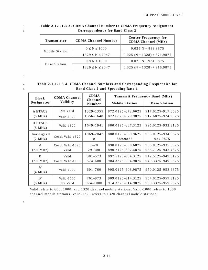
3GPP2 C.S0002-C v2.0
2-11
Table 2.1.1.1.3-3. CDMA Channel Number to CDMA Frequency Assignment 1
Correspondence for Band Class 2 2
Transmitter CDMA Channel Number Center Frequency for CDMA Channel (MHz)
0 ≤ N ≤ 1000 0.025 N + 889.9875 Mobile Station
1329 ≤ N ≤ 2047 0.025 (N − 1328) + 871.9875
0 ≤ N ≤ 1000 0.025 N + 934.9875 Base Station
1329 ≤ N ≤ 2047 0.025 (N − 1328) + 916.9875
3
Table 2.1.1.1.3-4. CDMA Channel Numbers and Corresponding Frequencies for 4
Band Class 2 and Spreading Rate 1 5
Transmit Frequency Band (MHz) Block Designator
CDMA Channel Validity
CDMA Channel Number Mobile Station Base Station
A ETACS (8 MHz)
Not Valid
Valid-1320
1329–1355 1356–1648
872.0125–872.6625 872.6875–879.9875
917.0125–917.6625 917.6875–924.9875
B ETACS (8 MHz)
Valid-1320 1649–1941 880.0125–887.3125 925.0125–932.3125
Unassigned (2 MHz)
Cond. Valid-1320 1969–2047
0 888.0125–889.9625
889.9875 933.0125–934.9625
934.9875
A (7.5 MHz)
Cond. Valid-1320
Valid
1–28 29–300
890.0125–890.6875 890.7125–897.4875
935.0125–935.6875 935.7125–942.4875
B (7.5 MHz)
Valid
Cond. Valid-1000
301–573 574–600
897.5125–904.3125 904.3375–904.9875
942.5125–949.3125 949.3375–949.9875
A′ (4 MHz)
Valid-1000 601–760 905.0125–908.9875 950.0125–953.9875
B′ (6 MHz)
Valid-1000
Not Valid
761–973 974–1000
909.0125–914.3125 914.3375–914.9875
954.0125–959.3125 959.3375–959.9875
Valid refers to 600, 1000, and 1320 channel mobile stations. Valid-1000 refers to 1000 channel mobile stations. Valid-1320 refers to 1320 channel mobile stations.
6

3GPP2 C.S0002-C v2.0
2-12
Table 2.1.1.1.3-5. CDMA Channel Numbers and Corresponding Frequencies for Band 1
Class 2 and Spreading Rate 3 2
Transmit Frequency Band (MHz) Block
Designator CDMA Channel
Validity
CDMA Channel Number Mobile Station Base Station
A ETACS (8 MHz)
Not Valid
Valid-1320
1329- Not specified
Not specified-1648
872.0125-Not specified
Not specified-879.9875
917.0125-Not specified
Not specified-924.9875
B ETACS (8 MHz)
Valid-1320 1649–1941 880.0125–887.3125 925.0125–932.3125
Unassigned (2 MHz)
Cond. Valid-1320
1969–2047 0
888.0125–889.9625 889.9875
933.0125–934.9625 934.9875
A (7.5 MHz)
Cond. Valid-1320
Valid
1-Not specified
Not specified-300
890.0125-Not specified
Not specified-897.4875
935.0125-Not specified
Not specified-942.4875
B (7.5 MHz)
Valid
Cond. Valid-1000
301–573
Not specified-600
897.5125–904.3125
Not specified-904.9875
942.5125–949.3125
Not specified-949.9875
A′ (4 MHz)
Valid-1000 601–760 905.0125–908.9875 950.0125–953.9875
B′ (6 MHz)
Valid-1000
Not Valid
761-Not specified
Not specified-1000
909.0125-Not specified
Not specified-914.9875
954.0125-Not specified
Not specified-959.9875
Valid refers to 600, 1000, and 1320 channel mobile stations. Valid-1000 refers to 1000 channel mobile stations. Valid-1320 refers to 1320 channel mobile stations.
3
Table 2.1.1.1.3-6. CDMA Preferred Set of Frequency Assignments for Band Class 2 4
Block Designator
Spreading Rate Preferred Set Channel Numbers
1 79, 679, or 1365 A
3 Not specified
1 379, 947, or 1932 B
3 Not specified
5

3GPP2 C.S0002-C v2.0
2-13
2.1.1.1.4 Band Class 3 (JTACS Band) 1
The Band Class 3 system designators for the mobile station and base station shall be as 2
specified in Table 2.1.1.1.4-1. 3
Mobile stations supporting Band Class 3 shall be capable of transmitting in Band Class 3. 4
The channel spacing, CDMA channel designations, and transmitter center frequencies of 5
Band Class 3 shall be as specified in Table 2.1.1.1.4-2. Mobile stations supporting Band 6
Class 3 and Spreading Rate 1 shall support transmission on the valid and conditionally 7
valid channel numbers shown in Table 2.1.1.1.4-3. Note that certain channel assignments 8
are not valid and others are conditionally valid. Transmission on conditionally valid 9
channels is permissible if the adjacent block is allocated to the same licensee or if other 10
valid authorization has been obtained. 11
Channel numbers for the Primary CDMA Channels and the Secondary CDMA Channels 12
are given in Table 2.1.1.1.4-4. 13
If the mobile station uses Spreading Rate 1 for both the Forward and the Reverse Traffic 14
Channel, then it shall transmit the Reverse Traffic Channel on the CDMA Channel 15
designated by CDMACHs. 16
If the mobile station is transmitting and receiving using the same spreading rate, the 17
nominal mobile station transmit carrier frequency shall be 55.0 MHz higher than the 18
frequency of the base station transmit signal as measured at the mobile station receiver. 19
20
Table 2.1.1.1.4-1. Band Class 3 System Frequency Correspondence 21
Transmit Frequency Band (MHz) System Designator Mobile Station Base Station
A
887.0125–888.9875 893.0125–898.0000 898.0125–900.9875 915.0125–924.9875
832.0125–833.9875 838.0125–843.0000 843.0125–845.9875 860.0125–869.9875
B Not specified Not specified
22

3GPP2 C.S0002-C v2.0
2-14
Table 2.1.1.1.4-2. CDMA Channel Number to CDMA Frequency Assignment 1
Correspondence for Band Class 3 2
Transmitter CDMA Channel Number Center Frequency for CDMA Channel (MHz)
1 ≤ N ≤ 799 0.0125 N + 915.000
801 ≤ N ≤ 1039 0.0125 (N – 800) + 898.000
1041 ≤ N ≤ 1199 0.0125 (N – 1040) + 887.000 Mobile Station
1201 ≤ N ≤ 1600 0.0125 (N – 1200) + 893.000
1 ≤ N ≤ 799 0.0125 N + 860.000
801 ≤ N ≤ 1039 0.0125 (N – 800) + 843.000
1041 ≤ N ≤ 1199 0.0125 (N – 1040) + 832.000 Base Station
1201 ≤ N ≤ 1600 0.0125 (N – 1200) + 838.000
In this table, only even-valued N values are valid.
3
Table 2.1.1.1.4-3. CDMA Channel Numbers and Corresponding Frequencies for 4
Band Class 3 and Spreading Rate 1 5
Transmit Frequency Band (MHz) System Designator
CDMA Channel Validity
CDMA Channel Number Mobile Station Base Station
A1 (2 MHz)
Not Valid Valid
Not Valid
1041–1099 1100–1140 1141–1199
887.0125–887.7375 887.7500–888.2500 888.2625–888.9875
832.0125–832.7375 832.7500–833.2500 833.2625–833.9875
A3 (5 MHz)
Not Valid Valid
Cond. Valid
1201–1259 1260–1540 1541–1600
893.0125–893.7375 893.7500–897.2500 897.2625–898.0000
838.0125–838.7375 838.7500–842.2500 842.2625–843.0000
A2 (3 MHz)
Cond. Valid Valid
Not Valid
801–859 860–980 981–1039
898.0125–898.7375 898.7500–900.2500 900.2625–900.9875
843.0125–843.7375 843.7500–845.2500 845.2625–845.9875
A (10 MHz)
Not Valid Valid
Not Valid
1–59 60–740 741–799
915.0125–915.7375 915.7500–924.2500 924.2625–924.9875
860.0125–860.7375 860.7500–869.2500 869.2625–869.9875
B Not specified Not specified Not specified Not specified
6

3GPP2 C.S0002-C v2.0
2-15
Table 2.1.1.1.4-4. CDMA Preferred Set of Frequency Assignments for Band Class 3 1
System Designator
Spreading Rate
Preferred Set Channel Numbers
A 1 76 (Primary) and 872 (Secondary)
B 1 Not specified
2
2.1.1.1.5 Band Class 4 (Korean PCS Band) 3
The Band Class 4 block designators for the mobile station and base station shall be as 4
specified in Table 2.1.1.1.5-1. 5
Mobile stations supporting Band Class 4 shall be capable of transmitting in Band Class 4. 6
The channel spacing, CDMA channel designations, and transmitter center frequencies of 7
Band Class 4 shall be as specified in Table 2.1.1.1.5-2. Mobile stations supporting Band 8
Class 4 and Spreading Rate 1 shall support transmission on the valid channel numbers 9
shown in Table 2.1.1.1.5-3. Mobile stations supporting Band Class 4 and Spreading Rate 3 10
shall support transmission on the valid channel numbers shown in Table 2.1.1.1.5-4. 11
Channel numbers for the Primary CDMA Channels and the Secondary CDMA Channels 12
are given in Table 2.1.1.1.5-5. 13
A preferred set of Sync Channel frequency assignments for the multi-carrier mode is given 14
in Table 2.1.1.1.5-6. 15
If the mobile station uses Spreading Rate 1 or Spreading Rate 3 for both the Forward and 16
the Reverse Traffic Channel, then it shall transmit the Reverse Traffic Channel on the 17
CDMA Channel designated by CDMACHs. If the mobile station uses Spreading Rate 3 for 18
the Forward Traffic Channel and uses Spreading Rate 1 for the Reverse Traffic Channel, 19
then it shall transmit the Reverse Traffic Channel on the CDMA Channel designated by 20
CDMACHs – 25 if 1XRL_FREQ_OFFSETs equals ‘00’, on the CDMA Channel designated by 21
CDMACHs if 1XRL_FREQ_OFFSETs equals ‘01’, or on the CDMA Channel designated by 22
CDMACHs + 25 if 1XRL_FREQ_OFFSETs equals ‘10’. 23
If the mobile station is transmitting and receiving using the same spreading rate, the 24
nominal mobile station transmit carrier frequency shall be 90.0 MHz lower than the 25
frequency of the base station transmit signal as measured at the mobile station receiver. If 26
the mobile station is transmitting on Spreading Rate 1 and receiving on Spreading Rate 3, 27
the nominal mobile station transmit carrier frequency shall be 90.0 – 1.25 × 28
(1XRL_FREQ_OFFSETs – 1) MHz lower than the center frequency of the center CDMA 29
channel transmitted by the base station as measured at the mobile station receiver. 30
31

3GPP2 C.S0002-C v2.0
2-16
Table 2.1.1.1.5-1. Band Class 4 Block Frequency Correspondence 1
Transmit Frequency Band (MHz) Block Designator Mobile Station Base Station
A 1750–1760 1840–1850
B 1760–1770 1850–1860
C 1770–1780 1860–1870
2
Table 2.1.1.1.5-2. CDMA Channel Number to CDMA Frequency Assignment 3
Correspondence for Band Class 4 4
Transmitter CDMA Channel Number Center Frequency for CDMA Channel (MHz)
Mobile Station 0 ≤ N ≤ 599 0.050 N + 1750.000
Base Station 0 ≤ N ≤ 599 0.050 N + 1840.000
5
Table 2.1.1.1.5-3. CDMA Channel Numbers and Corresponding Frequencies for Band 6
Class 4 and Spreading Rate 1 7
Transmit Frequency Band (MHz) Block Designator
CDMA Channel Validity
CDMA Channel Number Mobile Station Base Station
A (10 MHz)
Not Valid Valid
Cond. Valid
0−24 25−175 176−199
1750.000−1751.200 1751.250−1758.750 1758.800−1759.950
1840.000−1841.200 1841.250−1848.750 1848.800−1849.950
B (10 MHz)
Cond. Valid Valid
Cond. Valid
200−224 225−375 376−399
1760.000−1761.200 1761.250−1768.750 1768.800−1769.950
1850.000−1851.200 1851.250−1858.750 1858.800−1859.950
C (10 MHz)
Cond. Valid Valid
Not Valid
400−424 425−575 576−599
1770.000−1771.200 1771.250−1778.750 1778.800−1779.950
1860.000−1861.200 1861.250−1868.750 1868.800−1869.950
8

3GPP2 C.S0002-C v2.0
2-17
Table 2.1.1.1.5-4. CDMA Channel Numbers and Corresponding Frequencies for Band 1
Class 4 and Spreading Rate 3 2
Transmit Frequency Band (MHz) Block
Designator
CDMA Channel Validity
CDMA Channel Number Mobile Station Base Station
A (10 MHz)
Not Valid Valid
Cond. Valid
0−49 50−150 151−199
1750.000−1752.450 1752.500−1757.500 1757.550−1759.950
1840.000−1842.450 1842.500−1847.500 1847.550−1849.950
B (10 MHz)
Cond. Valid Valid
Cond. Valid
200−249 250−350 351−399
1760.000−1762.450 1762.500−1767.500 1767.550−1769.950
1850.000−1852.450 1852.500−1857.500 1857.550−1859.950
C (10 MHz)
Cond. Valid Valid
Not Valid
400−449 450−550 551−599
1770.000−1772.450 1772.500−1777.500 1777.550−1779.950
1860.000−1862.450 1862.500−1867.500 1867.550−1869.950
3
Table 2.1.1.1.5-5. CDMA Preferred Set of Frequency Assignments for Band Class 4 4
Block Designator
Spreading Rate Preferred Set Channel Numbers
1 25, 50, 75, 100, 125, 150, 175 A
3 50, 75, 100, 125, 150
1 225, 250, 275, 300, 325, 350, 375 B
3 250, 275, 300, 325, 350
1 425, 450, 475, 500, 525, 550, 575 C
3 450, 475, 500, 525, 550
5
Table 2.1.1.1.5-6. Sync Channel Preferred Set of Frequency Assignments for 6
Spreading Rate 3 for Band Class 4 7
Block Designator
Preferred Set of Channel Numbers
A 75, 150
B 275, 350
C 475, 550
8

3GPP2 C.S0002-C v2.0
2-18
2.1.1.1.6 Band Class 5 (450 MHz Band) 1
The Band Class 5 block designators for the mobile station and base station shall be as 2
specified in Table 2.1.1.1.6-1. 3
There are eight band subclasses specified for Band Class 5. Each band subclass 4
corresponds to a specific block designator (see Table 2.1.1.1.6-1). Each band subclass 5
includes all the channels designated for that block. Mobile stations supporting Band Class 6
5 shall be capable of transmitting in at least one band subclass belonging to Band Class 5. 7
For mobiles capable of transmitting in more than one band subclass belonging to Band 8
Class 5, one band subclass shall be designated as the Primary Band Subclass, which is 9
the band subclass used by the mobile’s home system. 10
The channel spacing, CDMA channel designations, and transmitter center frequencies of 11
Band Class 5 shall be as specified in Table 2.1.1.1.6-2. Mobile stations supporting Band 12
Class 5 and Spreading Rate 1 shall support transmission on the valid channel numbers 13
shown in Table 2.1.1.1.6-3, depending on the Band Subclass of mobile station. Mobile 14
stations supporting Band Class 5 and Spreading Rate 3 shall support transmission on the 15
valid channel numbers shown in Table 2.1.1.1.6-4, depending on the Band Subclass of 16
mobile station. 17
Channel numbers for the Primary CDMA Channels and the Secondary CDMA Channels 18
and the band subclasses are given in Table 2.1.1.1.6-5. 19
A preferred set of Sync Channel frequency assignments for the multi-carrier mode is given 20
in Table 2.1.1.1.6-6. 21
If the mobile station uses Spreading Rate 1 or Spreading Rate 3 for both the Forward and 22
the Reverse Traffic Channel, then it shall transmit the Reverse Traffic Channel on the 23
CDMA Channel designated by CDMACHs. If the mobile station uses Spreading Rate 3 for 24
the Forward Traffic Channel and uses Spreading Rate 1 for the Reverse Traffic Channel 25
and is operating in Band Subclass A, B, C, or E; then it shall transmit the Reverse Traffic 26
Channel on the CDMA Channel designated by CDMACHs – 50 if 1XRL_FREQ_OFFSETs 27
equals ‘00’, on the CDMA Channel designated by CDMACHs if 1XRL_FREQ_OFFSETs 28
equals ‘01’, or on the CDMA Channel designated by CDMACHs + 50 if 29
1XRL_FREQ_OFFSETs equals ‘10’. If the mobile station uses Spreading Rate 3 for the 30
Forward Traffic Channel and uses Spreading Rate 1 for the Reverse Traffic Channel and is 31
operating in Band Subclass F, G, or H; then it shall transmit the Reverse Traffic Channel 32
on the CDMA Channel designated by CDMACHs – 62 if 1XRL_FREQ_OFFSETs equals ‘00’, 33
on the CDMA Channel designated by CDMACHs if 1XRL_FREQ_OFFSETs equals ‘01’, or on 34
the CDMA Channel designated by CDMACHs + 62 if 1XRL_FREQ_OFFSETs equals ‘10’. 35
If the mobile station is transmitting and receiving using the same spreading rate, the 36
nominal mobile station transmit carrier frequency shall be 10.0 MHz lower than the 37
frequency of the base station transmit signal as measured at the mobile station receiver. If 38
the mobile station is transmitting on Spreading Rate 1 and receiving on Spreading Rate 3 39
and is operating in Band Subclass A, B, C, or E, the nominal mobile station transmit 40
carrier frequency shall be 10.0 – 1.25 × (1XRL_FREQ_OFFSETs – 1) MHz lower than the 41
frequency of the base station transmit signal as measured at the mobile station receiver. If 42
the mobile station is transmitting on Spreading Rate 1 and receiving on Spreading Rate 3 43

3GPP2 C.S0002-C v2.0
2-19
and is operating in Band Subclass F, G, or H, the nominal mobile station transmit carrier 1
frequency shall be 10.0 – 1.24 × (1XRL_FREQ_OFFSETs – 1) MHz lower than the center 2
frequency of the center CDMA channel transmitted by the base station as measured at the 3
mobile station receiver. 4
5
Table 2.1.1.1.6-1. Band Class 5 Block Frequency Correspondence 6
and Band Subclasses 7
Transmit Frequency Band (MHz) Block Designator
Band Subclass Mobile Station Base Station
A 0 452.500–457.475 462.500–467.475
B 1 452.000–456.475 462.000–466.475
C 2 450.000–454.800 460.000–464.800
D 3 411.675–415.850 421.675–425.850
E 4 415.500–419.975 425.500–429.975
F 5 479.000–483.480 489.000–493.480
G 6 455.230–459.990 465.230–469.990
H 7 451.310–455.730 461.310–465.730
8
Table 2.1.1.1.6-2. CDMA Channel Number to CDMA Frequency Assignment 9
Correspondence for Band Class 5 10
Transmitter CDMA Channel Number Center Frequency for CDMA Channel (MHz)
1 ≤ N ≤ 300 0.025 (N – 1) + 450.000
539 ≤ N ≤ 871 0.025 (N – 512) + 411.000
1039 ≤ N ≤ 1473 0.020 (N – 1024) + 451.010 Mobile Station
1792 ≤ N ≤ 2016 0.020 (N – 1792) + 479.000
1 ≤ N ≤ 300 0.025 (N – 1) + 460.000
539 ≤ N ≤ 871 0.025 (N – 512) + 421.000
1039 ≤ N ≤ 1473 0.020 (N – 1024) + 461.010 Base Station
1792 ≤ N ≤ 2016 0.020 (N – 1792) + 489.000
11

3GPP2 C.S0002-C v2.0
2-20
Table 2.1.1.1.6-3. CDMA Channel Numbers and Corresponding Frequencies for 1
Band Class 5 and Spreading Rate 1 2
Transmit Frequency Band (MHz) Block Designator
CDMA Channel Validity
CDMA Channel Number Mobile Station Base Station
A (4.5 MHz)
Not Valid Cond. Valid
Valid Not Valid
121–125 126–145 146–275 276–300
453.000–453.100 453.125–453.600 453.625–456.850 456.875–457.475
463.000–463.100 463.125–463.600 463.625–466.850 466.875–467.475
A′ (0.5 MHz)
Not Valid 101–120 452.500–452.975 462.500–462.975
B (4.5 MHz)
Not Valid Valid
Not Valid
81–105 106–235 236–260
452.000–452.600 452.625–455.850 455.875–456.475
462.000–462.600 462.625–465.850 465.875–466.475
C (4.8 MHz)
Not Valid Valid
Not Valid
1–25 26–168 169–193
450.000–450.600 450.625–454.175 454.200–454.800
460.000–460.600 460.625–464.175 464.200–464.800
D (4.2 MHz)
Not Valid Valid
Not Valid
539–563 564–681 682–706
411.675–412.275 412.300–415.225 415.250–415.850
421.675–422.275 422.300–425.225 425.250–425.850
E (4.5 MHz)
Not Valid Valid
Not Valid
692–716 717–846 847–871
415.500–416.100 416.125–419.350 419.375–419.975
425.500–426.100 426.125–429.350 429.375–429.975
F (4.5 MHz)
Not Valid Valid
Not Valid
1792–1822 1823–1985 1986–2016
479.000–479.600 479.620–482.860 482.880–483.480
489.000–489.600 489.620–492.860 492.880–493.480
G (4.76 MHz)
Not Valid Valid
Not Valid
1235–1265 1266–1442 1443–1473
455.230–455.830 455.850–459.370 459.390–459.990
465.230–465.830 465.850–469.370 469.390–469.990
H (4.42 MHz)
Not Valid Valid
Not Valid
1039–1069 1070–1229 1230–1260
451.310–451.910 451.930–455.110 455.130–455.730
461.310–461.910 461.930–465.110 465.130–465.730
3

3GPP2 C.S0002-C v2.0
2-21
Table 2.1.1.1.6-4. CDMA Channel Numbers and Corresponding Frequencies for 1
Band Class 5 and Spreading Rate 3 2
Transmit Frequency Band (MHz) Block Designator
CDMA Channel Validity
CDMA Channel Number Mobile Station Base Station
A (4.5 MHz)
Not Valid Valid
Not Valid
121–200 201
202–300
453.000–454.975 455.000
455.025–457.475
463.000–464.975 465.000
465.025–467.475
A′ (0.5 MHz)
Not Valid 101–120 452.500–452.975 462.500–462.975
B (4.5 MHz)
Not Valid Valid
Not Valid
81–170 171
172–260
452.000–454.225 454.250
454.275–456.475
462.000–464.225 464.250
464.275–466.475
C (4.8 MHz)
Not Valid Valid
Not Valid
1–96 97
98–193
450.000–452.375 452.400
452.425–454.800
460.000–462.375 462.400
462.425–464.800
D (4.2 MHz)
Not Valid 539–706 411.675–415.850 421.675–425.850
E (4.5 MHz)
Not Valid Valid
Not Valid
692–781 782
783–871
415.500–417.725 417.750
417.775–419.975
425.500–427.725 427.750
427.775–429.975
F (4.5 MHz)
Not Valid Valid
Not Valid
1792–1903 1904
1905–2016
479.000–481.220 481.240
481.260–483.480
489.000–491.220 491.240
491.260–493.480
G (4.76 MHz)
Not Valid Valid
Not Valid
1235–1353 1354
1355–1473
455.230–457.590 457.610
457.630–459.990
465.230–467.590 467.610
467.630–469.990
H (4.42 MHz)
Not Valid Valid
Not Valid
1039–1149 1150
1151–1260
451.310–453.510 453.530
453.550–455.730
461.310–463.510 463.530
463.550–465.730
3

3GPP2 C.S0002-C v2.0
2-22
Table 2.1.1.1.6-5. CDMA Preferred Set of Frequency Assignments for Band Class 5 1
Block Designator
Preferred Set Channel Numbers
A 160, 210*, 260
B 120, 170, 220*
C 47, 97, 147*
D 573, 623, 673*
E 731*, 781, 831
F 1841*, 1903, 1965
G 1291*, 1353, 1415
H 1089, 1151, 1213*
* CDMA frequency assignments that support inter-block roaming
2
Table 2.1.1.1.6-6. Sync Channel Preferred Set of Frequency Assignments for 3
Spreading Rate 3 for Band Class 5 4
Block Designator
Preferred Set Channel Numbers
A 210
B 220
C 147
E 731
F 1841
G 1291
H 1213
5
2.1.1.1.7 Band Class 6 (2 GHz Band) 6
The Band Class 6 block designators for the mobile station and base station are not 7
specified, since licensee allocations vary by regulatory body. 8
Mobile stations supporting Band Class 6 shall be capable of transmitting in Band Class 6. 9
The channel spacing, CDMA channel designations, and transmitter center frequencies of 10
Band Class 6 shall be as specified in Table 2.1.1.1.7-1. Mobile stations supporting Band 11
Class 6 and Spreading Rate 1 shall support transmission on the valid channel numbers 12
shown in Table 2.1.1.1.7-2. Mobile stations supporting Band Class 6 and Spreading Rate 3 13
shall support transmission on the valid channel numbers shown in Table 2.1.1.1.7-3. 14
A preferred set of CDMA frequency assignments is given in Table 2.1.1.1.7-4. 15

3GPP2 C.S0002-C v2.0
2-23
If the mobile station uses Spreading Rate 1 or Spreading Rate 3 for both the Forward and 1
the Reverse Traffic Channel, then it shall transmit the Reverse Traffic Channel on the 2
CDMA Channel designated by CDMACHs. If the mobile station uses Spreading Rate 3 for 3
the Forward Traffic Channel and uses Spreading Rate 1 for the Reverse Traffic Channel, 4
then it shall transmit the Reverse Traffic Channel on the CDMA Channel designated by 5
CDMACHs – 25 if 1XRL_FREQ_OFFSETs equals ‘00’, on the CDMA Channel designated by 6
CDMACHs if 1XRL_FREQ_OFFSETs equals ‘01’, or on the CDMA Channel designated by 7
CDMACHs + 25 if 1XRL_FREQ_OFFSETs equals ‘10’. 8
If the mobile station is transmitting and receiving using the same spreading rate, the 9
nominal mobile station transmit carrier frequency shall be 190.0 MHz lower than the 10
frequency of the base station transmit signal as measured at the mobile station receiver. If 11
the mobile station is transmitting on Spreading Rate 1 and receiving on Spreading Rate 3, 12
the nominal mobile station transmit carrier frequency shall be 190.0 – 1.25 × 13
(1XRL_FREQ_OFFSETs – 1) MHz lower than the center frequency of the center CDMA 14
channel transmitted by the base station as measured at the mobile station receiver. 15
16
Table 2.1.1.1.7-1. CDMA Channel Number to CDMA Frequency Assignment 17
Correspondence for Band Class 6 18
Transmitter CDMA Channel Number
Center Frequency for CDMA Channel (MHz)
Mobile Station 0 ≤ N ≤ 1199 1920.000 + 0.050 N
Base Station 0 ≤ N ≤ 1199 2110.000 + 0.050 N
19
Table 2.1.1.1.7-2. CDMA Channel Numbers and Corresponding Frequencies for Band 20
Class 6 and Spreading Rate 1 21
Transmit Frequency Band (MHz) CDMA Channel Validity
CDMA Channel Number Mobile Station Base Station
Not Valid Valid
Not Valid
0−24 25−1175
1176−1199
1920.000−1921.200 1921.250–1978.750 1978.800–1979.950
2110.000–2111.200 2111.250–2168.750 2168.800–2169.950
Channel numbers less than 1.25 MHz from the licensee’s band edge are not valid.
22

3GPP2 C.S0002-C v2.0
2-24
Table 2.1.1.1.7-3. CDMA Channel Numbers and Corresponding Frequencies for Band 1
Class 6 and Spreading Rate 3 2
Transmit Frequency Band (MHz) CDMA Channel Validity
CDMA Channel Number Mobile Station Base Station
Not Valid Valid
Not Valid
0−49 50−1150
1151−1199
1920.000−1922.450 1922.500–1977.500 1977.550–1979.950
2110.000–2112.450 2112.500–2167.500 2167.550–2169.950
Channel numbers less than 2.5 MHz from the licensee’s band edge are not valid.
3
Table 2.1.1.1.7-4. CDMA Preferred Set of Frequency Assignments for Band Class 6 4
Spreading Rate
Preferred Set Channel Numbers
1 25, 50,…, 1150, 1175
3 50, 75,…, 1125, 1150
5
2.1.1.1.8 Band Class 7 (700 MHz Band) 6
The Band Class 7 block designators for the mobile station and base station shall be as 7
specified in Table 2.1.1.1.8-1. 8
Mobile stations supporting Band Class 7 shall be capable of transmitting in Band Class 7. 9
The channel spacing, CDMA channel designations, and transmitter center frequencies of 10
Band Class 7 shall be as specified in Table 2.1.1.1.8-2. Mobile stations supporting Band 11
Class 7 and Spreading Rate 1 shall support operations on the valid and conditionally valid 12
channel numbers shown in Table 2.1.1.1.8-3. Mobile stations supporting Band Class 7 13
and Spreading Rate 3 shall support operations on the valid and conditionally valid 14
channel numbers shown in Table 2.1.1.1.8-4. Note that certain channel assignments are 15
not valid and others are conditionally valid. Transmission on conditionally valid channels 16
is permissible if the adjacent block is allocated to the same licensee or if other valid 17
authorization has been obtained. 18
A preferred set of CDMA frequency assignments is given in Table 2.1.1.1.8-5. 19
A preferred set of Sync Channel frequency assignments for the multi-carrier mode is given 20
in Table 2.1.1.1.8-6. 21

3GPP2 C.S0002-C v2.0
2-25
If the mobile station uses Spreading Rate 1 or Spreading Rate 3 for both the Forward and 1
the Reverse Traffic Channels, then it shall transmit the Reverse Traffic Channel on the 2
CDMA Channel designated by CDMACHs. If the mobile station uses Spreading Rate 3 for 3
the Forward Traffic Channel and uses Spreading Rate 1 for the Reverse Traffic Channel, 4
then it shall transmit the Reverse Traffic Channel on the CDMA Channel designated by 5
CDMACHs – 25 if 1XRL_FREQ_OFFSETs equals ‘00’, on the CDMA Channel designated by 6
CDMACHs if 1XRL_FREQ_OFFSETs equals ‘01’, or on the CDMA Channel designated by 7
CDMACHs + 25 if 1XRL_FREQ_OFFSETs equals ‘10’. 8
If the mobile station is transmitting and receiving using the same spreading rate, the 9
nominal mobile station transmit carrier frequency shall be 30.0 MHz higher than the 10
frequency of the base station transmit signal as measured at the mobile station receiver. If 11
the mobile station is transmitting on Spreading Rate 1 and receiving on Spreading Rate 3, 12
the nominal mobile station transmit carrier frequency shall be 30.0 + 1.25 × 13
(1XRL_FREQ_OFFSETs − 1) MHz higher than the center frequency of the center CDMA 14
channel transmitted by the base station as measured at the mobile station receiver. 15
16
Table 2.1.1.1.8-1. Band Class 7 Block Frequency Correspondence 17
Transmit Frequency Band (MHz) Block Designator Mobile Station Base Station
A 776–777 746–747
C 777–782 747–752
D 782–792 752–762
B 792–794 762–764
18
Table 2.1.1.1.8-2. CDMA Channel Number to CDMA Frequency Assignment 19
Correspondence for Band Class 7 20
Transmitter CDMA Channel Number
Center Frequency for CDMA Channel (MHz)
Mobile Station 0 ≤ N ≤ 359 776.000 + 0.050 N
Base Station 0 ≤ N ≤ 359 746.000 + 0.050 N
21

3GPP2 C.S0002-C v2.0
2-26
Table 2.1.1.1.8-3. CDMA Channel Numbers and Corresponding Frequencies for 1
Band Class 7 and Spreading Rate 1 2
Transmit Frequency Band (MHz) Block
Designator
CDMA Channel Validity
CDMA Channel Number Mobile Station Base Station
A (1 MHz)
Not Valid 0−19 776.000–776.950 746.000–746.950
C (5 MHz)
Not Valid Valid
Cond. Valid
20–44 45–95 96–119
777.000–778.200 778.250–780.750 780.800–781.950
747.000–748.200 748.250–750.750 750.800–751.950
D (10 MHz)
Cond. Valid Valid
Not Valid
120–144 145–295 296–319
782.000–783.200 783.250–790.750 790.800–791.950
752.000–753.200 753.250–760.750 760.800–761.950
B (2 MHz)
Not Valid 320–359 792.000–793.950 762.000–763.950
3
Table 2.1.1.1.8-4. CDMA Channel Numbers and Corresponding Frequencies for 4
Band Class 7 and Spreading Rate 3 5
Transmit Frequency Band (MHz) Block
Designator
CDMA Channel Validity
CDMA Channel Number Mobile Station Base Station
A (1 MHz)
Not Valid 0−19 776.000–776.950 746.000–746.950
C (5 MHz)
Not Valid Valid
Cond. Valid
20–69 70
71–119
777.000–779.450 779.500
779.550–781.950
747.000–749.450 749.500
749.550–751.950
D (10 MHz)
Cond. Valid Valid
Not Valid
120–169 170–270 271–319
782.000−784.450 784.500−789.500 789.550−791.950
752.000−754.450 754.500−759.500 759.550−761.950
B (2 MHz)
Not Valid 320–359 792.000−793.950 762.000−763.950
6

3GPP2 C.S0002-C v2.0
2-27
Table 2.1.1.1.8-5. CDMA Preferred Set of Frequency Assignments for Band Class 7 1
Block Designator
Spreading Rate
Preferred Set Channel Numbers
A N/A None
1 45, 70, 95 C
3 70
1 145, 170, 195, 220, 245, 270, 295 D
3 170, 195, 220, 245, 270
B N/A None
2
Table 2.1.1.1.8-6. Sync Channel Preferred Set of Frequency Assignments for 3
Spreading Rate 3 for Band Class 7 4
Block Designator
Preferred Set of Channel Numbers
A None
C 70
D 170, 245
B None
5
2.1.1.1.9 Band Class 8 (1800 MHz Band) 6
The Band Class 8 block designators for the mobile station and base station are not 7
specified. 8
Mobile stations supporting Band Class 8 shall be capable of transmitting in Band Class 8. 9
The channel spacing, CDMA channel designations, and transmitter center frequencies of 10
Band Class 8 shall be as specified in Table 2.1.1.1.9-1. Mobile stations supporting Band 11
Class 8 and Spreading Rate 1 shall support transmission on the valid channel numbers 12
shown in Table 2.1.1.1.9-2. Mobile stations supporting Band Class 8 and Spreading Rate 3 13
shall support transmission on the valid channel numbers shown in Table 2.1.1.1.9-3. 14
A preferred set of CDMA frequency assignments is given in Table 2.1.1.1.9-4. 15
If the mobile station uses Spreading Rate 1 or Spreading Rate 3 for both the Forward and 16
the Reverse Traffic Channel, then it shall transmit the Reverse Traffic Channel on the 17
CDMA Channel designated by CDMACHs. If the mobile station uses Spreading Rate 3 for 18
the Forward Traffic Channel and uses Spreading Rate 1 for the Reverse Traffic Channel, 19
then it shall transmit the Reverse Traffic Channel on the CDMA Channel designated by 20
CDMACHs – 25 if 1XRL_FREQ_OFFSETs equals ‘00’, on the CDMA Channel designated by 21
CDMACHs if 1XRL_FREQ_OFFSETs equals ‘01’, or on the CDMA Channel designated by 22
CDMACHs + 25 if 1XRL_FREQ_OFFSETs equals ‘10’. 23

3GPP2 C.S0002-C v2.0
2-28
If the mobile station is transmitting and receiving using the same spreading rate, the 1
nominal mobile station transmit carrier frequency shall be 95.0 MHz lower than the 2
frequency of the base station transmit signal as measured at the mobile station receiver. If 3
the mobile station is transmitting on Spreading Rate 1 and receiving on Spreading Rate 3, 4
the nominal mobile station transmit carrier frequency shall be 95.0 – 1.25 × 5
(1XRL_FREQ_OFFSETs – 1) MHz lower than the center frequency of the center CDMA 6
channel transmitted by the base station as measured at the mobile station receiver. 7
8
Table 2.1.1.1.9-1. CDMA Channel Number to CDMA Frequency Assignment 9
Correspondence for Band Class 8 10
Transmitter CDMA Channel
Number Center Frequency for CDMA Channel (MHz)
Mobile Station 0 ≤ N ≤ 1499 1710.000 + 0.050 N
Base Station 0 ≤ N ≤ 1499 1805.000 + 0.050 N
11
Table 2.1.1.1.9-2. CDMA Channel Numbers and Corresponding Frequencies for Band 12
Class 8 and Spreading Rate 1 13
Transmit Frequency Band (MHz) CDMA Channel Validity
CDMA Channel Number Mobile Station Base Station
Not Valid Valid
Not Valid
0−24 25−1475
1476−1499
1710.000−1711.200 1711.250–1783.750 1783.800–1784.950
1805.000–1806.200 1806.250–1878.750 1878.800–1879.950
Channel numbers less than 1.25 MHz from the licensee’s band edge are not valid.
14
Table 2.1.1.1.9-3. CDMA Channel Numbers and Corresponding Frequencies for Band 15
Class 8 and Spreading Rate 3 16
Transmit Frequency Band (MHz) CDMA Channel Validity
CDMA Channel Number Mobile Station Base Station
Not Valid Valid
Not Valid
0−49 50−1450
1451−1499
1710.000−1712.450 1712.500–1782.500 1782.550–1784.950
1805.000–1807.450 1807.500–1877.500 1877.550–1879.950
Channel numbers less than 2.5 MHz from the licensee’s band edge are not valid.
17

3GPP2 C.S0002-C v2.0
2-29
Table 2.1.1.1.9-4. CDMA Preferred Set of Frequency Assignments for Band Class 8 1
Spreading Rate
Preferred Set Channel Numbers
1 25, 50,…, 1450, 1475
3 50, 75,…, 1425, 1450
2
2.1.1.1.10 Band Class 9 (900 MHz Band) 3
The Band Class 9 block designators for the mobile station and base station are not 4
specified. 5
Mobile stations supporting Band Class 9 shall be capable of transmitting in Band Class 9. 6
The channel spacing, CDMA channel designations, and transmitter center frequencies of 7
Band Class 9 shall be as specified in Table 2.1.1.1.10-1. Mobile stations supporting Band 8
Class 9 and Spreading Rate 1 shall support transmission on the valid channel numbers 9
shown in Table 2.1.1.1.10-2. Mobile stations supporting Band Class 9 and Spreading Rate 10
3 shall support transmission on the valid channel numbers shown in Table 2.1.1.1.10-3. 11
A preferred set of CDMA frequency assignments is given in 12
Table 2.1.1.1.10-4. 13
If the mobile station uses Spreading Rate 1 or Spreading Rate 3 for both the Forward and 14
the Reverse Traffic Channel, then it shall transmit the Reverse Traffic Channel on the 15
CDMA Channel designated by CDMACHs. If the mobile station uses Spreading Rate 3 for 16
the Forward Traffic Channel and uses Spreading Rate 1 for the Reverse Traffic Channel, 17
then it shall transmit the Reverse Traffic Channel on the CDMA Channel designated by 18
CDMACHs – 25 if 1XRL_FREQ_OFFSETs equals ‘00’, on the CDMA Channel designated by 19
CDMACHs if 1XRL_FREQ_OFFSETs equals ‘01’, or on the CDMA Channel designated by 20
CDMACHs + 25 if 1XRL_FREQ_OFFSETs equals ‘10’. 21
If the mobile station is transmitting and receiving using the same spreading rate, the 22
nominal mobile station transmit carrier frequency shall be 45.0 MHz lower than the 23
frequency of the base station transmit signal as measured at the mobile station receiver. If 24
the mobile station is transmitting on Spreading Rate 1 and receiving on Spreading Rate 3, 25
the nominal mobile station transmit carrier frequency shall be 45.0 – 1.25 × 26
(1XRL_FREQ_OFFSETs – 1) MHz lower than the center frequency of the center CDMA 27
channel transmitted by the base station as measured at the mobile station receiver. 28
29

3GPP2 C.S0002-C v2.0
2-30
Table 2.1.1.1.10-1. CDMA Channel Number to CDMA Frequency Assignment 1
Correspondence for Band Class 9 2
Transmitter CDMA Channel
Number Center Frequency for CDMA Channel (MHz)
Mobile Station 0 ≤ N ≤ 699 880.000 + 0.050 N
Base Station 0 ≤ N ≤ 699 925.000 + 0.050 N
3
Table 2.1.1.1.10-2. CDMA Channel Numbers and Corresponding Frequencies for Band 4
Class 9 and Spreading Rate 1 5
Transmit Frequency Band (MHz) CDMA Channel Validity
CDMA Channel Number Mobile Station Base Station
Not Valid Valid
Not Valid
0−24 25−675 676−699
880.000−881.200 881.250–913.750 913.800–914.950
925.000–926.200 926.250–958.750 958.800–959.950
Channel numbers less than 1.25 MHz from the licensee’s band edge are not valid.
6
Table 2.1.1.1.10-3. CDMA Channel Numbers and Corresponding Frequencies for Band 7
Class 9 and Spreading Rate 3 8
Transmit Frequency Band (MHz) CDMA Channel Validity
CDMA Channel Number Mobile Station Base Station
Not Valid Valid
Not Valid
0−49 50−650 651−699
880.000−882.450 882.500–912.500 912.550–914.950
925.000–927.450 927.500–957.500 957.550–959.950
Channel numbers less than 2.5 MHz from the licensee’s band edge are not valid.
9
Table 2.1.1.1.10-4. CDMA Preferred Set of Frequency Assignments for Band Class 9 10
Spreading Rate Preferred Set Channel Numbers
1 25, 50,…, 650, 675
3 50, 75,…, 625, 650
11

3GPP2 C.S0002-C v2.0
2-31
2.1.1.1.11 Band Class 10 (Secondary 800 MHz Band) 1
The Band Class 10 system designators for the mobile station and base station shall be as 2
specified in Table 2.1.1.1.11-1. 3
There are five band subclasses specified for Band Class 10. Mobile stations supporting 4
Band Class 10 shall support at least one band subclass belonging to Band Class 10. 5
Mobile stations supporting Band Class 10 shall be capable of transmitting in Band Class 6
10. 7
The channel spacing, CDMA channel designations, and transmitter center frequencies of 8
Band Class 10 shall be as specified in Table 2.1.1.1.11-2. Mobile stations supporting Band 9
Class 10 and Spreading Rate 1 shall support transmission on the valid channel numbers 10
shown in Table 2.1.1.1.11-3. Mobile stations supporting Band Class 10 and Spreading 11
Rate 3 shall support operations on the valid channel numbers shown in Table 2.1.1.1.11-12
4. 13
A preferred set of CDMA frequency assignments is given in Table 2.1.1.1.11-5. 14
A preferred set of Sync Channel frequency assignments for the multi-carrier mode is given 15
in Table 2.1.1.1.11-6. 16
If the mobile station uses Spreading Rate 1 or Spreading Rate 3 for both the Forward and 17
the Reverse Traffic Channel, then it shall transmit the Reverse Traffic Channel on the 18
CDMA Channel designated by CDMACHs. If the mobile station uses Spreading Rate 3 for 19
the Forward Traffic Channel and uses Spreading Rate 1 for the Reverse Traffic Channel, 20
then it shall transmit the Reverse Traffic Channel on the CDMA Channel designated by 21
CDMACHs – 50 if 1XRL_FREQ_OFFSETs equals ‘00’, on the CDMA Channel designated by 22
CDMACHs if 1XRL_FREQ_OFFSETs equals ‘01’, or on the CDMA Channel designated by 23
CDMACHs + 50 if 1XRL_FREQ_OFFSETs equals ‘10’. 24
If the mobile station is transmitting and receiving using the same spreading rate, the 25
nominal mobile station transmit carrier frequency shall be 45.0 MHz (Band Subclasses 0, 26
1, 2, and 3) or 39.0 MHz (Band Subclass 4) lower than the frequency of the base station 27
transmit signal as measured at the mobile station receiver. If the mobile station is 28
transmitting on Spreading Rate 1 and receiving on Spreading Rate 3, the nominal mobile 29
station transmit carrier frequency shall be 45.0 – 1.25 × (1XRL_FREQ_OFFSETs – 1) MHz 30
(Band Subclass 0, 1, and 2) or 39.0 – 1.25 × (1XRL_FREQ_OFFSETs – 1) MHz (Band 31
Subclass 3) lower than the carrier frequency of the center CDMA channel transmitted by 32
the base station as measured at the mobile station receiver. 33
34

3GPP2 C.S0002-C v2.0
2-32
Table 2.1.1.1.11-1. Band Class 10 System Frequency Correspondence 1
Transmit Frequency Band (MHz) System Designator
Band Subclass Mobile Station Base Station
A 0 806.000–810.975 851.000–855.975
B 1 811.000–815.975 856.000–860.975
C 2 816.000–820.975 861.000–865.975
D 3 821.000–823.975 866.000–868.975
E 4 896.000–900.975 935.000–939.975
2
Table 2.1.1.1.11-2. CDMA Channel Number to CDMA Frequency Assignment 3
Correspondence for Band Class 10 4
Transmitter CDMA Channel Number Center Frequency for CDMA Channel (MHz)
0 ≤ N ≤ 719 0.025 N + 806.000 Mobile Station
720 ≤ N ≤ 919 0.025 (N − 720) + 896.000
0 ≤ N ≤ 719 0.025 N + 851.000 Base Station
720 ≤ N ≤ 919 0.025 (N − 720) + 935.000
5

3GPP2 C.S0002-C v2.0
2-33
Table 2.1.1.1.11-3. CDMA Channel Numbers and Corresponding Frequencies for 1
Band Class 10 and Spreading Rate 1 2
Transmit Frequency Band (MHz) Band Subclass
System Designator
CDMA Channel Validity
CDMA Channel Number Mobile Station Base Station
0 A Not Valid
Valid Cond. Valid
0–49 50–150 151–199
806.000–807.225 807.250–809.750 809.775–810.975
851.000–852.225 852.250–854.750 854.775–855.975
1 B Cond. Valid
Valid Cond. Valid
200–249 250–350 351–399
811.000–812.225 812.250–814.750 814.775–815.975
856.000–857.225 857.250–859.750 859.775–860.975
2 C Cond. Valid
Valid Cond. Valid
400–449 450–550 551–599
816.000–817.225 817.250–819.750 819.775–820.975
861.000–862.225 862.250–864.750 864.775–865.975
3 D Cond. Valid
Valid Not Valid
600–649 650–670 671–719
821.000–822.225 822.250–822.750 822.775–823.975
866.000–867.225 867.250–867.750 867.775–868.975
4 E Not Valid
Valid Not Valid
720–769 770–870 871–919
896.000–897.225 897.250–899.750 899.775–900.975
935.000–936.225 936.250–938.750 938.775–939.975
3

3GPP2 C.S0002-C v2.0
2-34
Table 2.1.1.1.11-4. CDMA Channel Numbers and Corresponding Frequencies for Band 1
Class 10 and Spreading Rate 3 2
Transmit Frequency Band (MHz) Band Subclass
System Designator
CDMA Channel Validity
CDMA Channel Number Mobile Station Base Station
0 A Not Valid
Valid Cond. Valid
0–99 100
101–199
806.000–808.475 808.500
808.525–810.975
851.000–853.475 853.500
853.525–855.975
1 B Cond. Valid
Valid Cond. Valid
200–299 300
301–399
811.000–813.475 813.500
813.525–815.975
856.000–858.475 858.500
858.525–860.975
2 C Cond. Valid
Valid Cond. Valid
400–499 500
501–599
816.000–818.475 818.500
818.525–820.975
861.000–863.475 863.500
863.525–865.975
3 D Cond. Valid Not Valid
600–620 621–719
821.000–821.500 821.525–823.975
866.000–866.500 866.525–868.975
4 E Not Valid
Valid Not Valid
720–769 770–870 871–919
896.000–897.225 897.250–99.750 899.775–900.975
935.000–936.225 936.250–938.750 938.775–939.975
3
Table 2.1.1.1.11-5. CDMA Preferred Set of Frequency Assignments for Band Class 10 4
Band Subclass
System Designator
Spreading Rate Preferred Set Channel Numbers
1 50, 100, 150, 0 A
3 100
1 250, 300, 350 1 B
3 300
1 450, 500, 550 2 C
3 500
1 650, 670 3 D
3 Not applicable
1 770, 820, 870 4 E
3 820
5

3GPP2 C.S0002-C v2.0
2-35
Table 2.1.1.1.11-6. Sync Channel Preferred Set of Frequency Assignments for 1
Spreading Rate 3 for Band Class 10 2
Band Subclass
System Designator
Preferred Set of Channel Numbers
0 A 150
1 B 300
2 C 450, 500
3 D Not applicable
4 E 820
3
2.1.1.1.12 Band Class 11 (400 MHz European PAMR Band) 4
The Band Class 11 block designators for the mobile station and base station shall be as 5
specified in Table 2.1.1.1.12-1. 6
There are sixfour band subclasses specified for Band Class 11. Each band subclass 7
corresponds to a specific block designator (see Table 2.1.1.1.12-1). Each band subclass 8
includes all the channels designated for that block. Mobile stations supporting Band Class 9
11 shall be capable of transmitting in at least one band subclass belonging to Band Class 10
11. For mobiles capable of transmitting in more than one band subclass belonging to 11
Band Class 11, one band subclass shall be designated as the Primary Band Subclass, 12
which is the band subclass used by the mobile’s home system. 13
The channel spacing, CDMA channel designations, and transmitter center frequencies of 14
Band Class 11 shall be as specified in Table 2.1.1.1.12-2. Mobile stations supporting Band 15
Class 11 and Spreading Rate 1 shall support transmission on the valid channel numbers 16
shown in Table 2.1.1.1.12-3, depending on the Band Subclass of mobile station. Mobile 17
stations supporting Band Class 11 and Spreading Rate 3 shall support transmission on 18
the valid channel numbers shown in Table 2.1.1.1.12-4 Table 2.1.1.1.11-4, depending on 19
the Band Subclass of the mobile station. 20
Channel numbers for the Primary CDMA Channels and the Secondary CDMA Channels 21
and the band subclasses are given in Table 2.1.1.1.12-5 Table 2.1.1.1.11-5. 22
A preferred set of Sync Channel frequency assignments for the multi-carrier mode is given 23
in Table 2.1.1.1.12-6 Table 2.1.1.1.11-6. 24
If the mobile station uses Spreading Rate 1 or Spreading Rate 3 for both the Forward and 25
the Reverse Traffic Channel, then it shall transmit the Reverse Traffic Channel on the 26
CDMA Channel designated by CDMACHs. If the mobile station uses Spreading Rate 3 for 27
the Forward Traffic Channel and uses Spreading Rate 1 for the Reverse Traffic Channel, 28
then it shall transmit the Reverse Traffic Channel on the CDMA Channel designated by 29
CDMACHs - 50 if 1XRL_FREQ_OFFSETs equals ‘00’, on the CDMA Channel designated by 30
CDMACHs if 1XRL_FREQ_OFFSETs equals ‘01’, or on the CDMA Channel designated by 31
CDMACHs + 50 if 1XRL_FREQ_OFFSETs equals ‘10’. 32

3GPP2 C.S0002-C v2.0
2-36
If the mobile station is transmitting and receiving using the same spreading rate, the 1
nominal mobile station transmit carrier frequency shall be 10.0 MHz lower than the 2
frequency of the base station transmit signal as measured at the mobile station receiver. If 3
the mobile station is transmitting on Spreading Rate 1 and receiving on Spreading Rate 3, 4
the nominal mobile station transmit carrier frequency shall be 10.0 - 1.25 × 5
(1XRL_FREQ_OFFSETs - 1) MHz lower than the frequency of the base station transmit 6
signal as measured at the mobile station receiver. 7
8
Table 2.1.1.1.12-1. Band Class 11 Block Frequency Correspondence 9
and Band Subclasses 10
Transmit Frequency Band (MHz) Block Designator
Band Subclass Mobile Station Base Station
A 0 452.500-457.475 462.500-467.475
B 1 410.000-414.975 420.000-424.975
C 2 415.000-419.975 425.000-429.975
D 3 451.000-455.975 461.000-465.975
E 4 415.000-417.975 425.000-427.975
F 5 452.500-455.475 462.500-465.475
11
Table 2.1.1.1.12-2. CDMA Channel Number to CDMA Frequency Assignment 12
Correspondence for Band Class 11 13
Transmitter CDMA Channel Number Center Frequency for CDMA Channel (MHz)
1 ≤≤ N ≤≤ 400 0.025 (N – -1) + 450.000
Mobile Station 1001 ≤≤ N ≤≤ 1400
0.025 (N – -1001) + 410.000
1 ≤≤ N ≤≤ 400 0.025 (N – -1) + 460.000
Base Station 1001 ≤≤ N ≤≤ 1400
0.025 (N – -1001) + 420.000
14

3GPP2 C.S0002-C v2.0
2-37
Table 2.1.1.1.12-3. CDMA Channel Numbers and Corresponding Frequencies for 1
Band Class 11 and Spreading Rate 1 2
Transmit Frequency Band (MHz) Block
Designator
Valid CDMA Frequency
Assignments
CDMA Channel Number Mobile Station Base Station
A (5 MHz)
Not Valid Valid
Not Valid
101–125 126–275 276–300
452.500–453.100 453.125–456.850 456.875–457.475
462.500–463.100 463.125–466.850 466.875–467.475
B (5 MHz)
Not Valid Valid
Not Valid
1001–1025 1026–1175 1176–1200
410.000–410.600 410.625–414.350 414.375–414.975
420.000–420.600 420.625–424.350 424.375–424.975
C (5 MHz)
Not Valid Valid
Not Valid
1201–1225 1226–1375 1376–1400
415.000–415.600 415.625–419.350 419.375–419.975
425.000–425.600 425.625–429.350 429.375–429.975
D (5 MHz)
Not Valid Valid
Not Valid
41–65 66–215 216–240
451.000–451.600 451.625–455.350 455.375–455.975
461.000–461.600 461.625–465.350 465.375–465.975
E
(3 MHz)
Not Valid
Valid
Not Valid
1201-1234
1235-1285
1286-1320
415.000-415.825
415.850-417.100
417.125-417.975
425.000–425.825
425.850–427.100
427.125–427.975
F
(3 MHz)
Not Valid
Valid
Not Valid
101–134
135–185
186–220
452.500–453.325
453.350–454.600
454.625–455.475
462.500–463.325
463.350–464.600
464.625–465.475
3
4

3GPP2 C.S0002-C v2.0
2-38
Table 2.1.1.1.12-4. CDMA Channel Numbers and Corresponding Frequencies for 1
Band Class 11 and Spreading Rate 3 2
Transmit Frequency Band (MHz) Block Designator
CDMA Channel Validity
CDMA Channel Number Mobile Station Base Station
A (5 MHz)
Not Valid Valid
Not Valid
101-200 201
202-300
452.500-454.975 455.000
455.025–457.475
462.500-464.975 465.000
465.025-467.475
B (5 MHz)
Not Valid Valid
Not Valid
1001–1100 1101
1102–1200
410.000–412.475 412.500
412.525–414.975
420.000–422.475 422.500
422.525–424.975
C (5 MHz)
Not Valid Valid
Not Valid
1201–1300 1301
1302–1400
415.000–417.475 417.500
417.525–419.975
425.000–427.475 427.500
427.525–429.975
D (5 MHz)
Not Valid Valid
Not Valid
41–140 141
142–240
451.000–453.475 453.500
453.525–455.975
461.000–463.475 463.500
463.525–465.975
E
(3 MHz) Not Valid 1201-1320 415.000–417.975 425.000–427.975
F
(3 MHz) Not Valid 101-220 452.500–455.475 462.500–465.475
3
Table 2.1.1.1.12-5. CDMA Preferred Set of Frequency Assignments for Band Class 11 4
and Spreading Rate1 5
Block Designator
Spreading Rate
Preferred Set Channel Numbers
1 151, 201, 251 A
3 201
1 1051, 1101, and 1151 B
3 1101
1 1251, 1301, and 1351 C
3 1301
1 91, 141, 191 D
3 141
E 1 1235, 1285
F 1 135, 185

3GPP2 C.S0002-C v2.0
2-39
1
2
3
Table 2.1.1.1.12-6. Sync Channel Preferred Set of Frequency Assignments for 4
Spreading Rate 3 for Band Class 1 5
Block Designator Preferred Set Channel Numbers
A 201
B 1101
C 1301
D 141
E None
F None
6
7
2.1.1.1.13 Band Class 12 (800 MHz PAMR Band) 8
The Band Class 12 block designators for the mobile station and base station are not 9
specified. 10
Mobile stations supporting Band Class 12 shall be capable of transmitting in Band Class 11
12. 12
The Band Class 12 block designators for the CDMA equipment shall be as specified in 13
Table 2.1.1.1.13-1. There are two band subclasses specified for Band Class 12. Each band 14
subclass corresponds to a specific block designator (see Table 2.1.1.1.13-1). Each band 15
subclass includes all the channels designated for that block. CDMA equipments 16
supporting Band Class 12 shall be capable of transmitting in at least one band subclass 17
belonging to Band Class 12. For CDMA equipments capable of transmitting in more than 18
one band subclass belonging to Band Class 12, one band subclass shall be designated as 19
the Primary Band Subclass, which is the band subclass used by the mobile’s home 20
system. 21
The channel spacing, CDMA channel designations, and transmitter center frequencies of 22
Band Class 12 shall be as specified in Table 2.1.1.1.13-2 Table 2.1.1.1.13-1. Mobile 23
stations supporting Band Class 12 and Spreading Rate 1 shall support transmission on 24
the valid channel numbers shown in Table 2.1.1.1.13-3 Table 2.1.1.1.13-2. Mobile stations 25
supporting Band Class 12 and Spreading Rate 3 shall support transmission on the valid 26
channel numbers shown in Table 2.1.1.1.13-4 Table 2.1.1.1.13-3. 27
A preferred set of CDMA frequency assignments is given in Table 2.1.1.1.13-5 Table 28
2.1.1.1.13-4. 29

3GPP2 C.S0002-C v2.0
2-40
If the mobile station uses Spreading Rate 1 or Spreading Rate 3 for both the Forward and 1
the Reverse Traffic Channel, then it shall transmit the Reverse Traffic Channel on the 2
CDMA Channel designated by CDMACHs. If the mobile station uses Spreading Rate 3 for 3
the Forward Traffic Channel and uses Spreading Rate 1 for the Reverse Traffic Channel, 4
then it shall transmit the Reverse Traffic Channel on the CDMA Channel designated by 5
CDMACHs - 50 if 1XRL_FREQ_OFFSETs equals ‘00’, on the CDMA Channel designated by 6
CDMACHs if 1XRL_FREQ_OFFSETs equals ‘01’, or on the CDMA Channel designated by 7
CDMACHs + 50 if 1XRL_FREQ_OFFSETs equals ‘10’. 8
If the mobile station is transmitting and receiving using the same spreading rate, the 9
nominal mobile station transmit carrier frequency shall be 45.0 MHz lower than the 10
frequency of the base station transmit signal as measured at the mobile station receiver. If 11
the mobile station is transmitting on Spreading Rate 1 and receiving on Spreading Rate 3, 12
the nominal mobile station transmit carrier frequency shall be 45.0 - 1.25 × 13
(1XRL_FREQ_OFFSETs - 1) MHz lower than the center frequency of the center CDMA 14
channel transmitted by the base station as measured at the mobile station receiver. 15
At the base station, if a Band Class 12 carrier operates with Spreading Rate 3, then all 16
three carriers shall be separated by 50 CDMA Channels (1.25 MHz separation). 17
18
Table 2.1.1.1.13-1. Band Class 12 Block Frequency Correspondence and Band 19
Subclasses 20
Transmit Frequency Band (MHz) Block Designator
Band Subclass Mobile Station Base Station
A 0 870.0125–875.9875 915.0125–920.9875
B 1 871.5125–874.4875 916.5125–919.4875
21
Table 2.1.1.1.13-2. CDMA Channel Number to CDMA Frequency Assignment 22
Correspondence for Band Class 12 23
Transmitter CDMA Channel Number
Center Frequency for CDMA Channel (MHz)
Mobile Station 0 ≤ N ≤ 239 870.0125 + 0.025 N
Base Station 0 ≤ N ≤ 239 915.0125 + 0.025 N

3GPP2 C.S0002-C v2.0
2-41
1
Table 2.1.1.1.13-3. CDMA Channel Numbers and Corresponding Frequencies for Band 2
Class 12 and Spreading Rate 1 3
Transmit Frequency Band (MHz) CDMA Channel Validity
CDMA Channel Number Mobile Station Base Station
Not Valid Valid Not Valid
0−64 65−214 215−239
870.0125−871.6125 871.6375-875.3625 875.3875-875.9875
915.0125−916.6125 916.6375-875.3625 920.3875-920.9875
Transmit Frequency Band (MHz) Block Designator
Valid CDMA Frequency Assignment
CDMA Channel Number Mobile Station Base Station
A (6MHz)
Not Valid Valid
Not Valid
0−64 65−214 215−239
870.0125−871.6125 871.6375–875.3625 875.3875–875.9875
915.0125−916.6125 916.6375–920.3625 920.3875–920.9875
B (3 MHz)
Not Valid Valid
Not Valid
60–93 94–144 145–179
871.5125–872.3375 872.3625–873.6125 873.6375–874.4875
916.5125–917.3375 917.3625–918.6125 918.6375–919.4875
4

3GPP2 C.S0002-C v2.0
2-42
1
Table 2.1.1.1.13-4. CDMA Channel Numbers and Corresponding Frequencies for Band 2
Class 12 and Spreading Rate 3 3
Transmit Frequency Band (MHz) Block Designator
Valid CDMA Frequency Assignment
CDMA Channel Number Mobile Station Base Station
A (6MHz)
Not Valid Valid
Not Valid
0−138 139
140−239
870.0125−873.4625 873.4875
873.5125–875.9875
915.0125−918.4625 918.4875
918.5125–920.9875
B (3 MHz)
Not Valid 60–179 871.5125–874.4875 916.5125–919.4875
4
Transmit Frequency Band (MHz) CDMA Channel Validity
CDMA Channel Number Mobile Station Base Station
Not Valid Valid Not Valid
0−138 139 140−239
870.0125−873.4625 873.4875 873.5125-875.9875
915.0125−918.4625 918.4875 918.5125-920.9875
5
Table 2.1.1.1.13-5. CDMA Preferred Set of Frequency Assignments for Band Class 12 6
Block Designator
Spreading Rate Preferred Set Channel Numbers
1 89, 139, 189 A
3 139
1 94, 144 B
3 None
7
Spreading Rate Preferred Set Channel Numbers
1 94, 144, 194
3 144
8
3GPP2 C.S0002-C v2.0
2-43
2.1.1.2 Frequency Tolerance 1
The mobile station shall meet the requirements in Section 4.1.1 of the current version 2
of [11]. 3
2.1.2 Power Output Characteristics 4
All power levels are referenced to the mobile station antenna connector unless otherwise 5
specified. 6
2.1.2.1 Maximum Output Power 7
The mobile station shall meet the requirements in Sections 4.4.5 and 5.1 of the current 8
version of [11]. 9
The mobile station shall be capable of transmitting at the minimum specified power level 10
when transmitting only on the Access Channel, Enhanced Access Channel, Reverse 11
Common Control Channel, or Reverse Fundamental Channel and when commanded to 12
maximum output power. The output power may be lower when transmitting on more than 13
one of the following: Reverse Dedicated Control Channel, Reverse Fundamental Channel, 14
Reverse Supplemental Channel, Reverse Supplemental Code Channel, Reverse 15
Acknowledgment Channel, or Reverse Channel Quality Indicator Channel. The mobile 16
station shall not exceed the maximum specified power levels under any circumstances. 17
2.1.2.2 Output Power Limits 18
2.1.2.2.1 Minimum Controlled Output Power 19
The mobile station shall meet the requirements in Section 4.4.6 of the current version 20
of [11]. 21
2.1.2.2.2 Gated Output Power 22
2.1.2.2.2.1 Gated Output Power Except During a Serving Frequency PUF Probe 23
The transmitter noise floor should be less than –60 dBm/1.23 MHz and shall be less than 24
–54 dBm/1.23 MHz. 25
The mobile station transmits at nominal controlled power levels only during gated-on 26
periods, which are defined as a power control group. 27
During gated-off periods, between the transmissions of power control groups, the mobile 28
station shall reduce its mean output power, either by at least 20 dB with respect to the 29
mean output power of the most recent gated-on power control group or to the transmitter 30
noise floor, whichever is the greater power. 31
Given an ensemble of K gated-on power control groups, all with the same mean output 32
power, the time response of the ensemble average shall be within the limits shown in 33
Figure 2.1.2.2.2.1-1. 34
This section applies to the following cases: 35

3GPP2 C.S0002-C v2.0
2-44
• When operating with Radio Configuration 1 or 2 in variable data rate transmission 1
mode (see 2.1.3.1.9.1), 2
• When operating with Reverse Pilot Channel gating (see 2.1.3.2.3), 3
• When transmitting the Enhanced Access Channel preamble or the Reverse 4
Common Control Channel preamble (see 2.1.3.4.2.3 and 2.1.3.5.2.3), 5
• When operating the Reverse Fundamental Channel gating with Reverse Radio 6
Configurations 3, 4, 5, orand 6 and gating is used. 7
• When operating with Reverse Channel Quality Indicator Channel gating. 8
9
(1.25 × K - 0.003) ms
20 dB or tonoise floor
Time response of theensemble average
(average power control group)
Mean output power ofthe ensemble average
(reference line)
µs 7 µs 7
3 dB
10
Figure 2.1.2.2.2.1-1. Transmission Envelope Mask (Average Gated-on Power 11
Control Group) 12
13
2.1.2.2.2.2 Gated Output Power During a Serving Frequency PUF Probe 14
If the mobile station transmits gated-off power control groups during the PUF recovery 15
time, the mobile station shall reduce its mean output power, either by at least 20 dB with 16
respect to the mean output power of the power control group prior to the final power 17
control group of the PUF Setup time, or to the transmitter noise floor, whichever is the 18
greater power. 19
2.1.2.2.3 Standby Output Power 20
The mobile station shall disable its transmitter except when transmitting on the Reverse 21
CDMA Channel. 22
3GPP2 C.S0002-C v2.0
2-45
When the transmitter of a mobile station is disabled, the output noise power spectral 1
density of the mobile station shall be less than –61 dBm/1 MHz for all frequencies within 2
the transmit bands that the mobile station supports. 3
2.1.2.3 Controlled Output Power 4
The mobile station shall provide three independent means for output power adjustment: 5
an open loop estimation performed by the mobile station, a closed loop correction 6
involving both the mobile station and the base station, and, for Radio Configurations 3 7
through 6, a code channel attribute adjustment performed by the mobile station and the 8
base station. 9
Accuracy requirements on the controlled range of mean output power (see 2.1.2.4) need 10
not apply for the following three cases: mean output power levels exceeding the minimum 11
EIRP at the maximum output power for the corresponding mobile station class (see 12
2.1.2.1); mean output power levels less than the minimum controlled output power (see 13
2.1.2.2.1); or mean input power levels exceeding -25 dBm within the 1.23 MHz CDMA 14
bandwidth for Spreading Rate 1 or –20 dBm within the 3.69 MHz CDMA bandwidth for 15
Spreading Rate 3. 16
2.1.2.3.1 Estimated Open Loop Output Power 17
In the following equations, mean power is referenced to the nominal CDMA Channel 18
bandwidth of 1.23 MHz for Spreading Rate 1 or 3.69 MHz for Spreading Rate 3. The offset 19
power is summarized in Table 2.1.2.3.1-1. 20
21

3GPP2 C.S0002-C v2.0
2-46
Table 2.1.2.3.1-1. Open Loop Power Offsets 1
Band Class
Forward Spreading
Rate
Reverse Spreading
Rate
Reverse Channels Offset Power6
Access Channel Reverse Traffic Channel (RC = 1 or 2)
–73 1 1
Enhanced Access Channel Reverse Common Control Channel Reverse Traffic Channel (RC = 3 or 4) Enhanced Access Channel Reverse Common Control Channel
Reverse Traffic Channel (RC = 3 or 4)
–81.5
1 Reverse Traffic Channel (RC = 3 or 4)
–76.5
0, 2, 3, 5, 7, 9, 10,
11, and 12
3
3 Enhanced Access Channel Reverse Common Control Channel Reverse Traffic Channel (RC = 5 or 6)
–76.5
Access Channel Reverse Traffic Channel (RC = 1 or 2)
–76 1 1
Enhanced Access Channel Reverse Common Control Channel Reverse Traffic Channel (RC = 3 or 4) Enhanced Access Channel Reverse Common Control Channel
Reverse Traffic Channel (RC = 3 or 4)
–84.5
1 Reverse Traffic Channel (RC = 3 or 4)
–79.5
1, 4, 6, and 8
3
3 Enhanced Access Channel Reverse Common Control Channel Reverse Traffic Channel (RC = 5 or 6)
–79.5
6For simplicity, the Offset Power constants are expressed without units. For example, –73 is equal to 10 × log10 (10–7.3 mW2).

3GPP2 C.S0002-C v2.0
2-47
1
2.1.2.3.1.1 Open Loop Output Power When Transmitting on the Access Channel 2
The mobile station shall transmit each Access probe at a mean output power level defined 3
by7 4
mean output power (dBm) = 5
– mean input power (dBm) 6
+ offset power (from Table 2.1.2.3.1-1) 7
+ interference correction 8
+ NOM_PWRs – 16 × NOM_PWR_EXTs 9
+ INIT_PWRs 10
+ PWR_LVL × PWR_STEPs, 11
where interference correction = min(max(–7 – ECIO, 0), 7), ECIO is the Ec/I0 (dB) per 12
carrier of the strongest active set pilot, measured within the previous 500 ms, and 13
PWR_LVL is a non-negative integer which is the power level adjustment step. 14
The mobile station shall determine Ec/I0 (dB) by taking the ratio of the received pilot 15
energy per chip, Ec, to the total received power spectral density (noise and signals), of at 16
most k usable multipath components, where k is the number of demodulating elements 17
supported by the mobile station. The mobile station shall determine the total received 18
power spectral density, I0, over 1.23 MHz. 19
During an Access probe transmission, the mobile station shall update the mean output 20
power in response to changes in the mean input power. For subsequent Access probes in 21
an Access probe sequence, the mobile station shall update the mean output power in 22
response to changes in the mean input power, the interference correction, and PWR_LVL. 23
For Band Classes 0 and 3, NOM_PWR_EXTs is set to 0 and the range of the NOM_PWRs – 24
16 × NOM_PWR_EXTs correction is from –8 to +7 dB. For Band Classes 1, 2, 4, 5, 6, 7, 8, 9, 25
and 10, the range of the NOM_PWRs – 16 × NOM_PWR_EXTs correction is from –24 to +7 26
dB. The range of the INIT_PWRs parameter is –16 to +15 dB, with a nominal value of 0 dB. 27
The range of the PWR_STEPs parameter is 0 to 7 dB. The accuracy of the adjustment to 28
the mean output power due to NOM_PWRs, NOM_PWR_EXTs, INIT_PWRs, or a single 29
Access probe correction of PWR_STEPs shall be ±0.5 dB or ±20% of the value in dB, 30
whichever is greater. 31
7The purpose of having both an INIT_PWRs and a NOM_PWR_EXTs value is to distinguish between
their use. If INIT_PWRs were 0, then NOM_PWRs – 16 × NOM_PWR_EXTs would be the correction
that should provide the correct received power at the base station. NOM_PWRs – 16 ×
NOM_PWR_EXTs allows the open loop estimation process to be adjusted for different operating
environments. INIT_PWRs is the adjustment that is made to the first Access Channel probe so that it
should be received at somewhat less than the required signal power. This conservatism partially
compensates for occasional, partially decorrelated path losses between the Forward CDMA Channel
and the Reverse CDMA Channel.

3GPP2 C.S0002-C v2.0
2-48
The mobile station shall support a total combined range of interference correction, 1
NOM_PWRs, NOM_PWR_EXTs, INIT_PWRs, and PWR_LVL × PWR_STEPs of at least ±32 dB 2
for mobile stations operating in Band Classes 0, 2, 3, 5, 7, 9, 10, 11, and 12, and ±40 dB 3
for mobile stations operating in Band Classes 1, 4, 6, and 8. 4
Prior to application of corrections from PWR_LVL × PWR_STEPs, closed loop power control 5
corrections, and with INIT_PWRs set to zero, the mobile station’s estimated open loop 6
mean output power should be within ±6 dB and shall be within ±9 dB of the value 7
determined by the following relationship: 8
mean output power (dBm) = 9
– mean input power (dBm) 10
+ offset power (from Table 2.1.2.3.1-1) 11
+ interference correction 12
+ NOM_PWRs –- 16 × NOM_PWR_EXTs. 13
This requirement shall be met over the full range of NOM_PWRs – 16 × NOM_PWR_EXTs 14
(from –8 to +7 dB for Band Classes 0 and 3, and from –24 to +7 dB for Band Classes 1, 2, 15
4, 5, 6, 7, 8, 9, 10, 11, and 12). 16
2.1.2.3.1.2 Open Loop Output Power When Transmitting on the Enhanced Access Channel 17
The mobile station shall transmit the Enhanced Access preamble (see 2.1.3.4.2.3) at a 18
mean output power defined by 19
mean pilot channel output power (dBm) = 20
– mean input power (dBm) 21
+ offset power (from Table 2.1.2.3.1-1) 22
+ interference correction 23
+ EACH_NOM_PWRs 24
+ EACH_INIT_PWRs 25
+ 6 26
+ PWR_LVL × EACH_PWR_STEPs, 27
where interference correction = min(max(IC_THRESHs – ECIO, 0), IC_MAXs), ECIO is the 28
Ec/I0 (dB) per carrier of the strongest active set pilot, measured within the previous 29
500 ms, and PWR_LVL is a non-negative integer which is the power level adjustment step. 30
The mobile station shall determine Ec/I0 (dB) by taking the ratio of the received pilot 31
energy per chip, Ec, to the total received power spectral density (noise and signals), of at 32
most k usable multipath components, where k is the number of demodulating elements 33
supported by the mobile station. While receiving Spreading Rate 1, the mobile station 34
shall determine the total received power spectral density, I0, over 1.23 MHz; while 35
receiving Spreading Rate 3, the mobile station shall determine the total received power 36
spectral density, I0, over 3.69 MHz. While receiving Spreading Rate 3, the mobile station 37
shall determine Ec/I0 by summing the Ec from each multipath component for all three 38
carriers and normalizing by I0. 39
During an initial Enhanced Access probe transmission, the mobile station shall update 40
the mean output power in response to changes in the mean input power. For subsequent 41

3GPP2 C.S0002-C v2.0
2-49
Enhanced Access probes in an Enhanced Access probe sequence, the mobile station shall 1
update the mean output power in response to changes in the mean input power, the 2
interference correction, and PWR_LVL. 3
After transmitting the Enhanced Access Channel preamble, and before receiving the first 4
valid power control bit, the mobile station shall transmit the Reverse Pilot Channel at a 5
mean output power defined by 6
mean pilot channel output power (dBm) = 7
– mean input power (dBm) 8
+ offset power (from Table 2.1.2.3.1-1) 9
+ interference correction 10
+ EACH_NOM_PWRs 11
+ EACH_INIT_PWRs 12
+ PWR_LVL × EACH_PWR_STEPs. 13
If closed loop power control is enabled for the Enhanced Access Channel, then after the 14
first valid power control bit is received, the mobile station shall transmit the Reverse Pilot 15
Channel during the Enhanced Access header and Enhanced Access data transmission at a 16
mean output power defined by 17
mean pilot channel output power (dBm) = 18
– mean input power (dBm) 19
+ offset power (from Table 2.1.2.3.1-1) 20
+ interference correction 21
+ EACH_NOM_PWRs 22
+ EACH_INIT_PWRs 23
+ PWR_LVL × EACH_PWR_STEPs 24
+ the sum of all closed loop power control corrections (dB). 25
The mobile station shall not update the interference correction after the first valid power 26
control bit is received. 27
The range of the EACH_NOM_PWRs correction is –16 to +15 dB. The range of the 28
EACH_INIT_PWRs parameter is –16 to +15 dB, with a nominal value of 0 dB. The range of 29
the EACH_PWR_STEPs parameter is 0 to 7 dB. The accuracy of the adjustment to the 30
mean output power due to EACH_NOM_PWRs, EACH_INIT_PWRs, or a single Enhanced 31
Access probe correction of EACH_PWR_STEPs shall be ±0.5 dB or ±20% of the value in dB, 32
whichever is greater. 33
The mobile station shall support a total combined range of interference correction, 34
EACH_NOM_PWRs, EACH_INIT_PWRs, and PWR_LVL × EACH_PWR_STEPs, and closed 35
loop power control corrections (if applicable) of at least ±32 dB for mobile stations 36
operating in Band Classes 0, 2, 3, 5, 7, 9, 10, 11, and 12, and of at least ±40 dB for mobile 37
stations operating in Band Classes 1, 4, 6, and 8. 38
Prior to application of corrections from PWR_LVL × EACH_PWR_STEPs, closed loop power 39
control corrections, with EACH_INIT_PWRs set to zero, and with the mobile station only 40
transmitting on the Reverse Pilot Channel, the mobile station’s estimated open loop mean 41

3GPP2 C.S0002-C v2.0
2-50
output power should be within ±6 dB and shall be within ±9 dB of the value determined 1
by the following relationship: 2
mean pilot channel output power (dBm) = 3
– mean input power (dBm) 4
+ offset power (from Table 2.1.2.3.1-1) 5
+ interference correction 6
+ EACH_NOM_PWRs. 7
This requirement shall be met over the full range of EACH_NOM_PWRs (from –16 to 8
+15 dB). 9
2.1.2.3.1.3 Open Loop Output Power When Transmitting on the Reverse Common Control 10
Channel 11
When operating in the Reservation Access Mode, the mobile station shall transmit the 12
Reverse Common Control Channel preamble (see 2.1.3.5.2.3) at a mean output power 13
defined by 14
mean pilot channel output power (dBm) = 15
– mean input power (dBm) 16
+ offset power (from Table 2.1.2.3.1-1) 17
+ interference correction 18
+ RCCCH_NOM_PWRs 19
+ RCCCH_INIT_PWRs 20
+ PREV_CORRECTIONS 21
+ 6, 22
where interference correction = min(max(IC_THRESHs – ECIO, 0), IC_MAXs), and ECIO is 23
the Ec/I0 (dB) per carrier of the strongest active set pilot, measured within the previous 24
500 ms. 25
The mobile station shall determine Ec/I0 (dB) by taking the ratio of the received pilot 26
energy per chip, Ec, to the total received power spectral density (noise and signals), of at 27
most k usable multipath components, where k is the number of demodulating elements 28
supported by the mobile station. While receiving Spreading Rate 1, the mobile station 29
shall determine the total received power spectral density, I0, over 1.23 MHz; while 30
receiving Spreading Rate 3, the mobile station shall determine the total received power 31
spectral density, I0, over 3.69 MHz. While receiving Spreading Rate 3, the mobile station 32
shall determine Ec/I0 by summing the Ec from each multipath component for all three 33
carriers and normalizing by I0. 34
The mobile station shall set PREV_CORRECTIONS to PWR_LVL × EACH_PWR_STEPs + 35
sum of all closed loop power control corrections, if applicable, from operation on the 36
Enhanced Access Channel. 37
After transmitting the Reverse Common Control Channel preamble while in the 38
Reservation Access Mode, and before receiving the first valid power control bit, the mobile 39
station shall transmit the Reverse Pilot Channel at a mean output power defined by 40

3GPP2 C.S0002-C v2.0
2-51
mean pilot channel output power (dBm) = 1
– mean input power (dBm) 2
+ offset power (from Table 2.1.2.3.1-1) 3
+ interference correction 4
+ RCCCH_NOM_PWRs 5
+ RCCCH_INIT_PWRs 6
+ PREV_CORRECTIONS., 7
After the first valid power control bit is received while in the Reservation Access Mode, the 8
mobile station shall transmit the Reverse Pilot Channel at a mean output power defined 9
by 10
mean pilot channel output power (dBm) = 11
– mean input power (dBm) 12
+ offset power (from Table 2.1.2.3.1-1) 13
+ interference correction 14
+ RCCCH_NOM_PWRs 15
+ RCCCH_INIT_PWRs 16
+ PREV_CORRECTIONS 17
+ the sum of all closed loop power control corrections (dB). 18
The mobile station shall not update the interference correction after the first power control 19
bit is received. 20
The range of the RCCCH_NOM_PWRs correction is –16 to +15 dB. The range of the 21
RCCCH_INIT_PWRs parameter is –16 to +15 dB, with a nominal value of 0 dB. The 22
accuracy of the adjustment to the mean output power due to RCCCH_NOM_PWRs or 23
RCCCH_INIT_PWRs shall be ±0.5 dB or ±20% of the value in dB, whichever is greater. 24
The mobile station shall support a total combined range of interference correction, 25
RCCCH_NOM_PWRs, RCCCH_INIT_PWRs, PREV_CORRECTIONS, and closed loop power 26
control corrections of at least ±32 dB for mobile stations operating in Band Classes 0, 2, 3, 27
5, 7, 9, 10, 11, and 12, and ±40 dB for mobile stations operating in Band Classes 1, 4, 6, 28
and 8. 29
Prior to application of closed loop power control corrections, with RCCCH_INIT_PWRs set 30
to zero, and with the mobile station only transmitting on the Reverse Pilot Channel, the 31
mobile station’s estimated open loop mean output power should be within ±6 dB and shall 32
be within ±9 dB of the value determined by the following relationship: 33
mean pilot channel output power (dBm) = 34
– mean input power (dBm) 35
+ offset power (from Table 2.1.2.3.1-1) 36
+ interference correction 37
+ RCCCH_NOM_PWRs 38
+ PREV_CORRECTIONS. 39
This requirement shall be met over the full range of RCCCH_NOM_PWRs (from –16 to 40
+15 dB). 41

3GPP2 C.S0002-C v2.0
2-52
2.1.2.3.1.4 Open Loop Output Power When Transmitting on the Reverse Traffic Channel 1
with Radio Configuration 1 or 2 2
The initial transmission on the Reverse Fundamental Channel with Radio Configurations 3
1 or 2 shall be at a mean output power defined by 4
mean output power (dBm) = 5
– mean input power (dBm) 6
+ offset power (from Table 2.1.2.3.1-1) 7
+ interference correction 8
+ ACC_CORRECTIONS 9
+ RLGAIN_ADJs, 10
where interference correction = min(max(–7 – ECIO, 0), 7), and ECIO is the Ec/I0 (dB) per 11
carrier of the strongest active set pilot, measured within the previous 500 ms. 12
The mobile station shall determine Ec/I0 (dB) by taking the ratio of the received pilot 13
energy per chip, Ec, to the total received power spectral density (noise and signals), of at 14
most k usable multipath components, where k is the number of demodulating elements 15
supported by the mobile station. The mobile station shall determine the total received 16
power spectral density, I0, over 1.23 MHz. 17
If the last channel used prior to operation on the Reverse Traffic Channel was the Access 18
Channel, the mobile station shall set ACC_CORRECTIONS to NOM_PWRs – 16 × 19
NOM_PWR_EXTs + INIT_PWRs + PWR_LVL × PWR_STEPs. 20
If the last channel used prior to operation on the Reverse Traffic Channel was the 21
Enhanced Access Channel, the mobile station shall set ACC_CORRECTIONS to 22
EACH_NOM_PWRs + EACH_INIT_PWRs + PWR_LVL × EACH_PWR_STEPs + sum of all 23
closed loop power control corrections (dB), if applicable. 24
If the last channel used prior to operation on the Reverse Traffic Channel was the Reverse 25
Common Control Channel, the mobile station shall set ACC_CORRECTIONS to 26
RCCCH_NOM_PWRs + RCCCH_INIT_PWRs + PREV_CORRECTIONS + sum of all closed loop 27
power control corrections (dB), if applicable. 28
After the first power control bit is received, the mean output power shall be defined by 29
mean output power (dBm) = 30
– mean input power (dBm) 31
+ offset power (from Table 2.1.2.3.2-1) 32
+ interference correction 33
+ ACC_CORRECTIONS 34
+ RLGAIN_ADJs 35
+ the sum of all closed loop power control corrections (dB) 36
+ 10 × log10 (1 + NUM_RSCCH) (dB), 37
where NUM_RSCCH is the number of Reverse Supplemental Code Channels on which the 38
mobile station is transmitting. The range of NUM_RSCCH is from 0 to 7. 39
The mobile station shall not update the interference correction after the first power control 40
bit is received. 41

3GPP2 C.S0002-C v2.0
2-53
The mobile station shall support a total combined range of interference correction, 1
ACC_CORRECTIONS, RLGAIN_ADJs, and closed loop power control corrections of at least 2
±32 dB for mobile stations operating in Band Classes 0, 2, 3, 5, 7, 9, 10, 11, and 12, and 3
±40 dB for mobile stations operating in Band Classes 1, 4, 6, and 8. 4
During a PUF pulse, the mean output power shall be defined by 5
mean output power (dBm) = 6
– mean input power (dBm) 7
+ offset power (from Table 2.1.2.3.1-1) 8
+ interference correction 9
+ ACC_CORRECTIONS 10
+ RLGAIN_ADJs 11
+ the sum of all closed loop power control corrections (dB) 12
+ PUF_INIT_PWRs 13
+ CURRENT_PUF_PROBEs × PUF_PWR_STEPs. 14
The mobile station shall not begin to increase power for a PUF pulse earlier than one 15
power control group before the beginning of the PUF pulse. The mean output power 16
should reach the PUF pulse power by the beginning of the PUF pulse, and shall reach the 17
PUF pulse power by the end of the first power control group of the PUF pulse. After the 18
end of a PUF pulse transmitted on the serving frequency, the mean output power shall 19
return to either the gated-on or gated-off level by the end of the first power control group 20
of the PUF recovery time. After the end of a PUF pulse transmitted on a PUF target 21
frequency, the mobile station shall disable the transmitter by the end of the first power 22
control group of the PUF recovery time. 23
During a PUF pulse, the mobile station shall support power increases from the nominal 24
up to the maximum output power. Immediately following the PUF pulse, the mobile 25
station shall decrement its output power to the nominal power or to the gated-off power 26
level with respect to the nominal output power. 27
The range of PUF_INIT_PWRs is 0 to 63 dB. The range of PUF_PWR_STEPs is 0 to 31 dB. 28
The range of CURRENT_PUF_PROBEs is 1 to 16. The accuracy of the adjustment to the 29
mean output power due to PUF_INIT_PWRs + (CURRENT_PUF_PROBEs × 30
PUF_PWR_STEPs) shall be ±1/3 of that value (in dB), or ±3 dB, whichever is greater, 31
unless the resulting mean output power exceeds the mobile station’s maximum output 32
power. If the output power exceeds the mobile station’s maximum output power, the mean 33
output power shall be within 3 dB of the maximum output power. See Figure 2.1.2.3.1.4-34
1. 35
36

3GPP2 C.S0002-C v2.0
2-54
PUF_PULSE_SIZES
0 1 M...
First power controlgroup of PUF pulse
Last power controlgroup of PUF pulse
Last power controlgroup of PUF setup
Nominal power + X
Lower bound onpower level
Upper bound onpower level
1.25 ms(1 PCG)
1.25 ms(1 PCG)
max[1/3(X),3]
max[1/3(X),3]
First power controlgroup of PUF recovery
3 dB
Nominal power level
Nominal power levelor gated-off with
respect to nominalpower level
Note: X = PUF_INIT_PWRS + (CURRENT_PUF_PROBES x PUF_PWR_STEPS) 1
Figure 2.1.2.3.1.4-1. Power Up Function Transmission Envelope Mask 2
3
2.1.2.3.1.5 Open Loop Output Power When Transmitting on the Reverse Traffic Channel 4
with Radio Configuration 3, 4, 5, or 6 5
The initial transmission on the Reverse Pilot Channel when transmitting a Reverse Traffic 6
Channel with Radio Configuration 3, 4, 5, or 6 shall be at a mean output power defined by 7
mean pilot channel output power (dBm) = 8
– mean input power (dBm) 9
+ offset power (from Table 2.1.2.3.1-1) 10
+ interference correction 11
+ ACC_CORRECTIONS 12
+ RLGAIN_ADJs, 13
where interference correction = min(max(IC_THRESHs – ECIO, 0), 7), and ECIO is the 14
Ec/I0 (dB) per carrier of the strongest active set pilot, measured within the previous 500 15
ms. 16
The mobile station shall determine Ec/I0 (dB) by taking the ratio of the received pilot 17
energy per chip, Ec, to the total received power spectral density (noise and signals), of at 18
most k usable multipath components, where k is the number of demodulating elements 19
supported by the mobile station. While receiving Spreading Rate 1, the mobile station 20
shall determine the total received power spectral density, I0, over 1.23 MHz; while 21
receiving Spreading Rate 3, the mobile station shall determine the total received power 22
spectral density, I0, over 3.69 MHz. While receiving Spreading Rate 3 operation, the 23
mobile station shall determine Ec/I0 by summing the Ec from each multipath component 24
for all three carriers and normalizing by I0. 25

3GPP2 C.S0002-C v2.0
2-55
If the last channel used prior to operation on the Reverse Traffic Channel was the Access 1
Channel, the mobile station shall set ACC_CORRECTIONS to NOM_PWRs – 16 × 2
NOM_PWR_EXTs + INIT_PWRs + PWR_LVL × PWR_STEPs. 3
If the last channel used prior to operation on the Reverse Traffic Channel was the 4
Enhanced Access Channel, the mobile station shall set ACC_CORRECTIONS to 5
EACH_NOM_PWRs + EACH_INIT_PWRs + PWR_LVL × PWR_STEPs + sum of all closed loop 6
power control corrections (dB), if applicable. 7
If the last channel used prior to operation on the Reverse Traffic Channel was the Reverse 8
Common Control Channel, the mobile station shall set ACC_CORRECTIONS to 9
RCCCH_NOM_PWRs + RCCCH_INIT_PWRs + PREV_CORRECTIONS + sum of all closed loop 10
power control corrections (dB), if applicable. 11
After the first valid power control bit is received, the mean output power shall be defined 12
by 13
mean pilot channel output power (dBm) = 14
– mean input power (dBm) 15
+ offset power (from Table 2.1.2.3.1-1) 16
+ interference correction 17
+ ACC_CORRECTIONS 18
+ RLGAIN_ADJs 19
+ the sum of all closed loop power control corrections. 20
The mobile station shall not update the interference correction after the first power control 21
bit is received. 22
The mobile station shall support a total combined range of interference correction, 23
ACC_CORRECTIONS, RLGAIN_ADJs, and closed loop power control corrections of at least 24
±32 dB for mobile stations operating in Band Classes 0, 2, 3, 5, 7, 9, 10, 11, and 12, and 25
±40 dB for mobile stations operating in Band Classes 1, 4, 6, and 8. 26
2.1.2.3.2 Closed Loop Output Power 27
For closed loop correction on the Reverse Common Control Channel (with respect to the 28
open loop estimate), the mobile station shall adjust its mean output power level in 29
response to each valid power control bit (see 3.1.3.7) received on the Forward Common 30
Power Control Channel. The nominal change in mean output power per single power 31
control bit shall be 1 dB. 32
For closed loop correction on the Reverse Traffic Channel, Reverse Acknowledgment 33
Channel, and Reverse Channel Quality Indicator Channel (with respect to the open loop 34
estimate), the mobile station shall adjust its mean output power level in response to each 35
valid power control bit (see 3.1.3.1.11) received on the Forward Fundamental Channel, the 36
Forward Dedicated Control Channel, or the Forward Common Power Control Channel. 37
For Radio Configuration 1 and 2, a power control bit shall be considered valid if it is 38
received in the second 1.25 ms time slot following a time slot in which the mobile station 39
transmitted (see 3.1.3.1.11), except during a PUF probe. During a PUF probe, the mobile 40
station shall consider a power control bit to be valid if it is received on the serving 41

3GPP2 C.S0002-C v2.0
2-56
frequency in the second 1.25 ms time slot following a time slot in which the mobile station 1
transmitted at the nominal power on the serving frequency. A power control bit received 2
on the fForward pPower cControl sSubchannel is considered invalid if it is received in the 3
second 1.25 ms time slot following a time slot in which the mobile station transmitter was 4
gated off, was changing power levels to increase power for the PUF pulse, was transmitting 5
at the PUF pulse power level, or was changing power levels to decrease power after the 6
PUF pulse. 7
For Reverse Pilot Channel gating (see 2.1.3.2.3) with Radio Configurations 3 through 6, a 8
power control bit shall be considered valid if it is received during a power control group in 9
which the fForward pPower cControl sSubchannel was transmitted (see 3.1.3.1.11). 10
Otherwise, it shall be considered invalid. For gated transmission other than the Reverse 11
Pilot Channel gating mode with Radio Configurations 3 through 6, a power control bit 12
shall be considered valid if it is received in the 1.25 ms time slot that starts 13
(REV_PWR_CNTL_DELAYs + 1) × 1.25 ms following the end of a time slot in which the 14
mobile station transmitted (see 3.1.3.1.11). For gated transmission other than the Reverse 15
Pilot Channel gating mode with Radio Configurations 3 through 6, a power control bit 16
received on the fForward pPower cControl sSubchannel or on the assigned subchannel of 17
the Common Power Control Channel is considered invalid if it is received in the 1.25 ms 18
time slot that starts (REV_PWR_CNTL_DELAYs + 1) × 1.25 ms following the end of a time 19
slot in which the mobile station transmitter was gated off. 20
If the mobile station does not support operation on the Reverse Supplemental Channel or 21
the Reverse Supplemental Code Channel, then the mobile station shall support a 1 dB 22
step size. Otherwise, the mobile station shall support 0.5 dB and 1 dB step sizes. The 23
mobile station may also support any additional step sizes in Table 2.1.2.3.2-1. If a 0.25 dB 24
step size is supported, then the 0.5 dB and 1 dB step sizes shall be supported. The 25
nominal change in mean output power per single power control bit shall be as specified in 26
Table 2.1.2.3.2-1 for the corresponding power control step size (PWR_CNTL_STEPs). The 27
total change in the closed loop mean output power shall be the accumulation of the valid 28
level changes. The mobile station shall lock the accumulation of valid level changes and 29
shall ignore received power control bits when the transmitter is disabled. The total 30
changed closed loop mean output power shall be applied to the total transmit power of the 31
mobile station. 32
33
Table 2.1.2.3.2-1. Closed Loop Power Control Step Size 34
PWR_CNTL_STEPs Power Control Step Size
(dB nominal) Tolerance
(dB)
0 1 ±0.5
1 0.5 ±0.3
2 0.25 ±0.2
35
The change in mean output power per single power control bit shall be within the 36
tolerance specified in Table 2.1.2.3.2-1 for the corresponding power control step size. For 37

3GPP2 C.S0002-C v2.0
2-57
the 1.0 dB step size, the change in mean output power level per 10 valid power control 1
bits of the same sign shall be within ±2.0 dB of 10 times the nominal change (10 dB). For 2
the 0.5 dB step size, the change in mean output power level per 20 valid power control 3
bits of the same sign shall be within ±2.5 dB of 20 times the nominal change (10 dB). For 4
the 0.25 dB step size, the change in mean output power level per 40 valid power control 5
bits of the same sign shall be within ±3.0 dB of 40 times the nominal change (10 dB). A ‘0’ 6
power control bit implies an increase in transmit power; and a ‘1’ power control bit implies 7
a decrease in transmit power. 8
The mobile station shall provide a closed loop adjustment range greater than ±24 dB 9
around its open loop estimate. 10
For the Reverse Traffic Channel with Radio Configuration 1 or 2, if the mobile station is 11
unable to transmit at the requested output power level, it shall discontinueterminate 12
transmission on at least one active Reverse Supplemental Code Channel, not later than 13
the transmission of the next 20 ms frame to maintain the requested output power on the 14
Reverse Fundamental Channel. 15
For the Reverse Traffic Channel with Radio Configuration 3 through 6, if the mobile 16
station is unable to transmit at the requested output power level, it shall reduce the data 17
rate on the Reverse Fundamental Channel, or reduce the transmission power or 18
discontinueterminate transmission on at least one of the following code channels that are 19
active: the Reverse Fundamental Channel, the Reverse Supplemental Channels, or the 20
Reverse Dedicated Control Channel, the Reverse Channel Quality Indicator Channel, or 21
the Reverse Acknowledgment Channel. The mobile station should not discontinue the 22
transmission on the Reverse Channel Quality Indicator Channel while switching to a 23
target base station. The mobile station shall perform this action not later than the 20 ms 24
frame boundary occurring no later than 40 ms after determining that the mobile station is 25
unable to transmit at the requested output power level. The mobile station should attempt 26
to reduce the transmission power, the data rate, or discontinueterminate transmission 27
first on the code channel with the lowest priority. The mobile station shall transmit at the 28
commanded output power level on the Reverse Pilot Channel. 29
2.1.2.3.3 Code Channel Output Power for Other than the Reverse Pilot Channel 30
2.1.2.3.3.1 Code Channel Output Power for the Enhanced Access Channel Header, 31
Enhanced Access Channel Data, and Reverse Common Control Channel Data 32
The mobile station shall set the output power of the Enhanced Access Channel Header, 33
Enhanced Access Channel Data, and the Reverse Common Control Channel Data relative 34
to the output power of the Reverse Pilot Channel. The mobile station shall transmit the 35
Enhanced Access Channel Header, Enhanced Access Channel Data, and Reverse Common 36
Control Channel Data at an output power given by8 37
8 The values of
Nominal_Reverse_Common_Channel_Attribute_Gain[Rate, Frame Duration] and RLGAIN_COMMONTRAFFIC_PILOTs

3GPP2 C.S0002-C v2.0
2-58
mean code channel output power (dBm) = 1
mean pilot channel output power (dBm) 2
+ 0.125 × Nominal_Reverse_Common_Channel_Attribute_Gain 3
[Rate, Frame Duration] 4
+ 0.125 × RLGAIN_COMMON_PILOTs. 5
The mobile station shall maintain a nNominal rReverse cCommon cChannel aAttribute 6
gGain tTable providing the values for Nominal_Reverse_Common_Channel_Attribute_Gain, 7
which is containing the relative header gain for the Enhanced Access Channel Header, or, 8
and the relative data gain for the Enhanced Access Channel Data orand Reverse Common 9
Channel Data for each data rate and frame duration supported by the mobile station. The 10
mobile station shall use the values given in Table 2.1.2.3.3.1-1. 11
12
Table 2.1.2.3.3.1-1. Nominal Reverse Common Channel Attribute Gain Table 13
Data Rate (bps)
Frame Length
(ms)
Nominal_Reverse _Common_Channel
_Attribute_Gain
9,600 5 (Header) 54
9,600 20 30
19,200 10 64
19,200 20 50
38,400 5 88
38,400 10 80
38,400 20 72
14
The mobile station shall maintain the ratio 15
power output channel pilot mean power output channel code mean 16
within ±0.25 dB of the number specified by 17
0.125 × (Nominal_Reverse_Common_Channel_Attribute_Gain 18
[Rate, Frame Duration]) 19
+ 0.125 × RLGAIN_COMMON_PILOTs. 20
are integers, specified in units of 0.125 dB.

3GPP2 C.S0002-C v2.0
2-59
2.1.2.3.3.2 Code Channel Output Power for the Reverse Acknowledgment Channel 1
The mobile station shall set the output power of the Reverse Acknowledgment Channel 2
relative to the output power of the Reverse Pilot Channel. The mobile station shall 3
transmit the Reverse Acknowledgment Channel at an output power given by9 4
mean code channel output power (dBm) = 5
mean pilot channel output power (dBm) 6
+ 0.125 × (Nominal_Reverse_Acknowledgment_Channel_Attribute_Gain 7
+ Reverse_Channel_Adjustment_Gain[Channel] 8
– Multiple_Channel_Adjustment_Gain[Channel] 9
+ RLGAIN_ ACKCQICH_PILOTs), 10
where Channel identifies the Reverse Acknowledgment Channel. The definitions for the 11
terms in the above equation can be found in 2.1.2.3.3.4. 12
The mobile station shall maintain a nNominal Reverse Acknowledgment Channel 13
aAttribute gGain tTable providing the value for 14
Nominal_Reverse_Acknowledgment_Channel_Attribute_Gain, which is containing the 15
relative gain for the Reverse Acknowledgment Channel given in Table 2.1.2.3.3.2-1. 16
17
18
Table 2.1.2.3.3.2-1. Nominal Reverse Acknowledgment Channel Attribute Gain Table 19
Nominal_Reverse_Acknowledgment_Channel_ Attribute_Gain
Pilot_Reference_Level
0–24 0
20
The mobile station shall maintain the ratio 21
power output channel pilot mean power output channel code mean 22
within ±0.25 dB of the number specified by 23
9 The values of
Nominal_Reverse_Acknowledgment_Channel_Attribute_Gain,
Reverse_Channel_Adjustment_Gain[Channel],
Multiple_Channel_Adjustment_Gain[Channel], and RLGAIN_ ACKCQICH_PILOTs
are integers, specified in units of 0.125 dB.

3GPP2 C.S0002-C v2.0
2-60
0.125 × (Nominal_Reverse_Acknowledgment_Channel_Attribute_Gain 1
+ Reverse_Channel_Adjustment_Gain[Channel] 2
– Multiple_Channel_Adjustment_Gain[Channel] 3
+ RLGAIN_ACKCQICH_PILOTs), 4
if the Reverse Acknowledgment Channel has an output power greater than 1/30 of the 5
total output power of the mobile station. The mobile station shall maintain the above ratio 6
to within ±0.35 dB if the Reverse Acknowledgment Channel has an output power greater 7
than 1/60 and less than 1/30 of the total output power of the mobile station. The mobile 8
station shall maintain the above ratio to within ±0.6 dB for the Reverse Acknowledgment 9
Channel having an output power less than 1/60 of the total output power of the mobile 10
station. 11
The mobile station shall support a total range of at least –(0.125 × Maximum_Pilot_ 12
Reference_Level + 4) dB to +4 dB for adjustment to the nominal mean code channel 13
output power given by 14
mean code channel output power (dBm) = 15
mean pilot channel output power (dBm) 16
+ 0.125 × Nominal_Reverse_Acknowledgment_Channel_Attribute_Gain. 17
The adjustment to the mean code channel output power (dB) is given by: 18
0.125 × (Reverse_Channel_Adjustment_Gain[Channel] 19
– Multiple_Channel_Adjustment_Gain[Channel] 20
+ RLGAIN_ACKCQICH_PILOTs). 21
Maximum_Pilot_Reference_Level is the Nominal_Pilot_Reference_Level given in Table 22
2.1.2.3.3.4-1 and Table 2.1.2.3.3.4-2 for the highest data rate transmitted by the mobile 23
station. 24
2.1.2.3.3.3 Code Channel Output Power for the Reverse Channel Quality Indicator 25
Channel 26
The mobile station shall set the output power of the Reverse Channel Quality Indicator 27
Channel relative to the output power of the Reverse Pilot Channel. The mobile station 28
shall transmit the Reverse Channel Quality Indicator Channel at an output power given 29
by10 30
10 The values of
Nominal_ Reverse_Channel_Quality_Indicator_Channel_Attribute_Gain[CQI_GAIN],
Reverse_Channel_Quality_Indicator_Channel_Attribute_Adjustment_Gain[CQI_GAIN],
Reverse_Channel_Adjustment_Gain[Channel],
Multiple_Channel_Adjustment_Gain[Channel], and RLGAIN_ACKCQICH_PILOTs
are integers, specified in units of 0.125 dB.

3GPP2 C.S0002-C v2.0
2-61
mean code channel output power (dBm) = 1
mean pilot channel output power (dBm) 2
+ 0.125 × (Nominal_Reverse_Channel_Quality_Indicator_ 3
Channel_Attribute_Gain[CQI_GAIN] 4
+ Reverse_Channel_Quality_Indicator_Channel_Attribute_ 5
Adjustment_Gain[CQI_GAIN] 6
+ Reverse_Channel_Adjustment_Gain[Channel] 7
– Multiple_Channel_Adjustment_Gain[Channel] 8
+ RLGAIN_TRAFFIC_PILOTs), 9
where Channel identifies the Reverse Channel Quality Indicator Channel. The definitions 10
for the terms in the above equation can be found in 2.1.2.3.3.4. 11
The mobile station shall maintain a nNominal Reverse Channel Quality Indicator Channel 12
aAttribute gGain tTable providing the values for 13
Nominal_Reverse_Channel_Quality_Indicator_Channel_Attribute_Adjustment_Gain, which 14
is containing the relative gain for the Reverse Channel Quality Indicator Channel for each 15
value of CQI_GAIN as indicated by the MAC Layer. The mobile station shall use the values 16
given in Table 2.1.2.3.3.3-1. 17
The mobile station shall maintain a Reverse Channel Quality Indicator Channel Link 18
aAttribute aAdjustment gGain tTable providing the values of 19
Reverse_Channel_Quality_Indicator_Channel_Attribute_Adjustment_Gain, which 20
iscontaining an offset relative to the Reverse Pilot Channel power for each value of 21
CQI_GAIN as indicated by the MAC Layer. The mobile station shall initialize each entry in 22
this table to 0. 23
24
Table 2.1.2.3.3.3-1. Nominal Reverse Channel Quality Indicator Channel Attribute 25
Gain Table 26
CQI_GAIN Nominal_Reverse_Channel_Quality_Indicator_Channel_ Attribute_Gain
Pilot_Reference_ Level
LOW –56 0
HIGH 16 0
27
The mobile station shall maintain the ratio 28
power output channel pilot mean power output channel code mean 29
within ±0.25 dB of the number specified by 30

3GPP2 C.S0002-C v2.0
2-62
0.125 × (Nominal_Reverse_Channel_Quality_Indicator_Channel_ 1
Attribute_Gain[CQI_GAIN] 2
+ Reverse_Channel_Quality_Indicator_Channel_Attribute_ 3
Adjustment_Gain[CQI_GAIN] 4
+ Reverse_Channel_Adjustment_Gain[Channel] 5
– Multiple_Channel_Adjustment_Gain[Channel] 6
+ RLGAIN_ACKCQICH_PILOTs), 7
if the Reverse Channel Quality Indicator Channel has an output power greater than 1/30 8
of the total output power of the mobile station. The mobile station shall maintain the 9
above ratio to within ±0.35 dB if the Reverse Channel Quality Indicator Channel has an 10
output power greater than 1/60 and less than 1/30 of the total output power of the 11
mobile station. The mobile station shall maintain the above ratio to within ±0.6 dB for the 12
Reverse Channel Quality Indicator Channel having an output power less than 1/60 of the 13
total output power of the mobile station. 14
The mobile station shall support a total range of at least –(0.125 × Maximum_Pilot_ 15
Reference_Level + 5) dB to +2 dB for adjustment to the nominal mean code channel 16
output power given by 17
mean code channel output power (dBm) = 18
mean pilot channel output power (dBm) 19
+ 0.125 × Nominal_Reverse_Channel_Quality_Indicator_Channel_ 20
Attribute_Gain[CQI_GAIN] 21
for each value of CQI_GAIN. The adjustment to the mean code channel output power (dB) 22
is given by: 23
0.125 × (Reverse_Channel_Quality_Indicator_Channel_ 24
Attribute_Adjustment_Gain[CQI_GAIN] 25
+ Reverse_Channel_Adjustment_Gain[Channel] 26
– Multiple_Channel_Adjustment_Gain[Channel] 27
+ RLGAIN_ACKCQICH_PILOTs)s. 28
Maximum_Pilot_Reference_Level is the Nominal_Pilot_Reference_Level given in Table 29
2.1.2.3.3.4-1 and Table 2.1.2.3.3.4-2 for the highest data rate transmitted by the mobile 30
station. 31
2.1.2.3.3.4 Code Channel Output Power for the Reverse Traffic Channel with Radio 32
Configuration 3, 4, 5, or 6 33
The mobile station shall set the output power of the Reverse Fundamental Channel, the 34
Reverse Supplemental Channel, and the Reverse Dedicated Control Channel relative to 35
the output power of the Reverse Pilot Channel. The mobile station shall transmit each of 36
the Reverse Fundamental Channel, Reverse Supplemental Channel, and Reverse 37
Dedicated Control Channel at an output power given by11 38
11 The values of

3GPP2 C.S0002-C v2.0
2-63
mean code channel output power (dBm) = 1
mean pilot channel output power (dBm) 2
+ 0.125 × (Nominal_Attribute_Gain[Rate, Frame Duration, Coding] 3
+ Attribute_Adjustment_Gain[Rate, Frame Duration, Coding] 4
+ Reverse_Channel_Adjustment_Gain[Channel] 5
– Multiple_Channel_Adjustment_Gain[Rate, Channel] 6
– Variable_Supplemental_Adjustment_Gain[Rate, Channel] 7
+ RLGAIN_TRAFFIC_PILOTs 8
+ RLGAIN_SCH_PILOTs[Channel]s) 9
+ IFHHO_SRCH_CORR, 10
where Channel identifies the Fundamental Channel, the Dedicated Control Channel, and 11
each Supplemental Channel. 12
The mobile station shall maintain a rReverse lLink nNominal aAttribute gGain tTable 13
provding the values for Nominal_Attribute_Gain, which is containing the nominal Reverse 14
Fundamental Channel, Reverse Supplemental Channel, or Reverse Dedicated Control 15
Channel power relative to the Reverse Pilot Channel power for each data rate listed in 16
Table 2.1.2.3.3.4-1 and Table 2.1.2.3.3.4-2, frame duration, and type of coding rate 17
supported by the mobile station. The mobile station shall use the values given in Table 18
2.1.2.3.3.4-1 and Table 2.1.2.3.3.4-2. 19
If flexible data rates are supported, and if the specified data rate, coding, and frame length 20
are not specified in the rReverse lLink aAttribute gGain tTable, the gain shall be 21
determined by linearly interpolating the values of Nominal_Attribute_Gain and the 22
Nominal_Pilot_Reference_Level to the nearest integer from the nearest data rates above 23
and below the specified data rate with the same frame length and coding. If the specified 24
data rate is below the lowest listed data rate with the same frame length and coding, the 25
gain shall be determined by linearly extrapolating the values of Nominal_Attribute_Gain 26
and the Nominal_Pilot_Reference_Level to the nearest integer from the two lowest data 27
rates with the same frame length and coding in the rReverse lLink aAttribute gGain 28
tTable. If variable-rate Reverse Supplemental Channel is supported and the mobile station 29
is transmitting using these rates, Pilot_Reference_Level of the highest assigned data rate 30
shall be used for all the data rates on the Reverse Supplemental Channel. 31
When the transmission on the Reverse Fundamental Channel is gated at the 1500 bps 32
data rate in Radio Configuration 3 or 5, or at the 1800 bps data rate in Radio 33
Configuration 4 or 6, the mobile station shall use the rReverse lLink nNominal aAttribute 34
gGain values given in Table 2.1.2.3.3.4-3. 35
Nominal_Attribute_Gain[Rate, Frame Duration, Coding],
Attribute_Adjustment_Gain[Rate, Frame Duration, Coding],
Reverse_Channel_Adjustment_Gain[Channel],
Multiple_Channel_Adjustment_Gain[Channel], and RLGAIN_TRAFFIC_PILOTs, and RLGAIN_SCH_PILOTs[Channel]s
are integers, specified in units of 0.125 dB.

3GPP2 C.S0002-C v2.0
2-64
The mobile station shall maintain a rReverse lLink aAttribute aAdjustment gGain tTable 1
providing the values for Attribute_Adjustment_Gain, which is containing an offset relative 2
to the Reverse Pilot Channel power for each data rate, frame duration, and type of coding 3
rate supported by the mobile station. 4
The mobile station shall maintain a reverse link pilot attribute adjustment gain table 5
providing the values for Pilot_Attribute_Adjustment_Gain, which is an adjustment to the 6
reverse pilot reference level for each data rate, frame duration, and type of coding 7
supported by the mobile station. The mobile station shall initialize each entry in theseis 8
two tables to 0.12 9
The mobile station shall maintain a rReverse cChannel aAdjustment gGain tTable 10
providing the values for Reverse_Channel_Adjustment_Gain, which is containing an offset 11
relative to Reverse Pilot Channel power for each reverse link code channel supported by 12
the mobile station. The mobile station shall initialize each entry in this table to 0. 13
The adjustment RLGAIN_SCH_PILOTs[Channel]s is valid for the Reverse Supplemental 14
Channel. 15
The mobile station shall adjust the mean code channel output power for each of the 16
Reverse Fundamental Channel, Reverse Supplemental Channel, and Reverse Dedicated 17
Control Channel by 0.125 × RLGAIN_TRAFFIC_PILOTs (dB). 18
If the mobile station is assigned only one code channel in addition to the Reverse Pilot 19
Channel, then the mobile station shall set Multiple_Channel_Adjustment_Gain [Rate, 20
Channel] to 0 for all assigned data rates on the code channels. If the mobile station is 21
assigned two or more code channels in addition to the Reverse Pilot Channel, then the 22
mobile shall set Multiple_Channel_Adjustment_Gain[Rate, Channel] for each assigned 23
data rate on each channel as follows13: 24
• Set Pilot_Reference_Level[Rate, Channel] to Nominal_Pilot_Reference_Level[Rate, 25
Channel] + Pilot_Attribute_Adjustment_Gain[Rate, Channel]. 26
• Let Max_Channel identify the code channel with the assigned data rate that has 27
the highest Pilot_Reference_Level among the code channels on which the mobile 28
station is assigned. 29
• Set Multiple_Channel_Adjustment_Gain[Rate, Max_Channel] to 0 for all assigned 30
data rates on Max_Channel. 31
12 The format of these twois tables areis similar to that of the rReverse lLink nNominal aAttribute
gGain tTable.
13 Multiple_Channel_Adjustment_Gain, Nominal_Pilot_Reference_Level and Pilot_Reference_Level
can be referred without the parameter ‘Rate’ for certain channels where the rate information is not
available, or Pilot_Reference_Level is not a function of data rate.

3GPP2 C.S0002-C v2.0
2-65
• For all assigned data rates on other code channels, set 1
Multiple_Channel_Adjustment_Gain [Rate, Channel] to 2
Pilot_Reference_Level[Max_Rate, Max_Channel] –- Pilot_Reference_Level[Rate, 3
Channel], where Max_Rate is the data rate on the Max_Channel with the highest 4
Pilot_Reference_Level among all assigned data rates. 5
If variable-rate Reverse Supplemental Channel operation is supported and the mobile 6
station is assigned to transmitt using these rates on a Reverse Supplemental Channel, 7
then the mobile station shall set Variable_Supplemental_Adjustment_Gain[Rate, Channel] 8
for each assigned data rate on each channel as follows: 9
• Let Max_Channel identify the code channel with the assigned data rate that has 10
the highest Pilot_Reference_Level among the code channels on which the mobile 11
station is assigned. 12
• If Max_Channel is not a Reverse Supplemental Channel with variable data rates, 13
set all Variable_Supplemental_Adjustment_Gain[Rate, Channel] to 0. 14
• Otherwise, set Variable_Supplemental_Adjustment_Gain[Rate, Max_Channel] to 15
Pilot_Reference_Level[Max_Rate, Max_Channel] –- Pilot_Reference_Level[Rate, 16
Max_Channel] for all rates on the Max_Channel except Max_Rate the maximum 17
assigned rate on that channel, where Max_Rate is the data rate on the 18
Max_Channel with the highest Pilot_Reference_Level among all assigned data 19
rates. Set Variable_Supplemental_Adjustment_Gain[Rate, Channel] to 0 for 20
Max_Rate on Max_Channel and all assigned data rates on other channels. 21

3GPP2 C.S0002-C v2.0
2-66
Table 2.1.2.3.3.4-1. Reverse Link Nominal Attribute Gain Table (Part 1 of 2) 1
Data Rate (bps)
Frame Length
(ms)
Coding Nominal_ Attribute
_Gain
Nominal_Pilot_Reference
_Level
Target Error Rate14
1,200 80 Convolutional –56 0 0.05
1,350 40 Convolutional –54 0 0.05
1,500 20 Convolutional –47 0 0.01
1,800 20 Convolutional –42 3 0.01
1,800 40 or 80 Convolutional –45 3 0.05
2,400 40 or 80 Convolutional –30 0 0.05
2,700 20 Convolutional –22 0 0.01
3,600 20 Convolutional –13 3 0.01
3,600 40 or 80 Convolutional –17 3 0.05
4,800 20 Convolutional –2 0 0.01
4,800 40 or 80 Convolutional –3 0 0.05
7,200 20 Convolutional 15 3 0.01
7,200 40 or 80 Convolutional 10 3 0.05
9,600 20 Convolutional 30 0 0.01
9,600 40 or 80 Convolutional 24 0 0.05
9,600 (RC 3 and 5)
5 Convolutional 58 0 0.01
9,600 (RC 4 and 6)
5 Convolutional 54 3 0.01
14,400 20 Convolutional 44 3 0.01
14,400 40 or 80 Convolutional 40 3 0.05
19,200 20, 40, or 80 Convolutional 50 1 0.05
28,800 20, 40, or 80 Convolutional 56 11 0.05
38,400 20, 40, or 80 Convolutional 60 11 0.05
57,600 20, 40, or 80 Convolutional 72 18 0.05
76,800 20, 40, or 80 Convolutional 72 21 0.05
115,200 20, 40, or 80 Convolutional 80 32 0.05
2
14 The error rate is the frame error rate when a single transmission unit is used; otherwise, the
Logical Transmission Unit (LTU) error rate is used. This applies to the cases in which the Target
Error Rate is 0.05.

3GPP2 C.S0002-C v2.0
2-67
Table 2.1.2.3.3.4-2. Reverse Link Nominal Attribute Gain Table (Part 2 of 2) 1
Data Rate (bps)
Frame Length
(ms)
Coding Nominal_ Attribute
_Gain
Nominal_Pilot_Reference
_Level
Target Error Rate
153,600 20, 40, or 80 Convolutional 84 36 0.05
230,400 20 or 40 Convolutional 88 46 0.05
259,200 80 Convolutional 96 50 0.05
307,200 20 or 40 Convolutional 96 54 0.05
460,800 20 Convolutional 104 61 0.05
518,400 40 Convolutional 104 64 0.05
614,400 20 Convolutional 112 68 0.05
1,036,800 20 Convolutional 128 83 0.05
4,800 80 Turbo 2 0 0.05
7,200 80 Turbo 24 0 0.05
9,600 40 or 80 Turbo 34 0 0.05
14,400 40 or 80 Turbo 42 0 0.05
19,200 20, 40, or 80 Turbo 44 2 0.05
28,800 20, 40, or 80 Turbo 52 9 0.05
38,400 20, 40, or 80 Turbo 56 10 0.05
57,600 20, 40, or 80 Turbo 64 19 0.05
76,800 20, 40, or 80 Turbo 68 19 0.05
115,200 20, 40, or 80 Turbo 76 29 0.05
153,600 20, 40, or 80 Turbo 76 33 0.05
230,400 20 or 40 Turbo 88 39 0.05
259,200 80 Turbo 88 48 0.05
307,200 20 or 40 Turbo 88 50 0.05
460,800 20 Turbo 104 54 0.05
518,400 40 Turbo 108 56 0.05
614,400 20 Turbo 112 58 0.05
1,036,800 20 Turbo 125 78 0.05
2

3GPP2 C.S0002-C v2.0
2-68
Table 2.1.2.3.3.4-3. Reverse Link Nominal Attribute Gain Values for the Reverse 1
Fundamental Channel at the 1500 bps or 1800 bps Data Rate during Gated 2
Transmission 3
Data Rate (bps)
Frame Length
(ms)
Coding Nominal_ Attribute
_Gain
Nominal_Pilot_Reference
_Level
Target Error Rate
1,500 20 Convolutional –10 0 0.01
1,800 20 Convolutional –2 3 0.01
4
The mobile station shall maintain the ratio 5
power output channel pilot mean power output channel code mean 6
within ±0.25 dB of the number specified by: 7
0.125 × (Nominal_Attribute_Gain[Rate, Frame Duration, Coding] 8
+ Attribute_Adjustment_Gain[Rate, Frame Duration, Coding] 9
+ Reverse_Channel_Adjustment_Gain[Channel] 10
– Multiple_Channel_Adjustment_Gain[Channel] 11
– Variable_Supplemental_Adjustment_Gain[Channel] 12
+ RLGAIN_TRAFFIC_PILOTs 13
+ RLGAIN_SCH_PILOTs[Channel]s) 14
+ IFHHO_SRCH_CORR 15
for every code channel (i.e., the Reverse Fundamental Channel, Reverse Supplemental 16
Channel, or Reverse Dedicated Control Channel) having an output power greater than 17
1/30 of the total output power of the mobile station. The mobile station shall maintain the 18
above ratio to within ±0.35 dB for every code channel having an output power greater than 19
1/60 and less than 1/30 of the total output power of the mobile station. The mobile 20
station shall maintain the above ratio to within ±0.6 dB for code channel having an output 21
power less than 1/60 of the total output power of the mobile station. 22
If the mobile station reduces the data rate or terminates transmission on a code channel 23
for any other reason than being commanded by the base station or reaching the end of an 24
allowed transmission period, the mobile station shall not change 25
Multiple_Channel_Adjustment_Gain for any code channel. 26
The mobile station shall support a total range of at least –(0.125 × Maximum_Pilot_ 27
Reference_Level + 4) dB to +6 dB for adjustment to the nominal mean code channel 28
output power given by: 29
mean code channel output power (dBm) = 30
mean pilot channel output power (dBm) 31
+ 0.125 × Nominal_Attribute_Gain[Rate, Frame Duration, Coding]. 32
The adjustment to the mean code channel output power (dB) is given by: 33
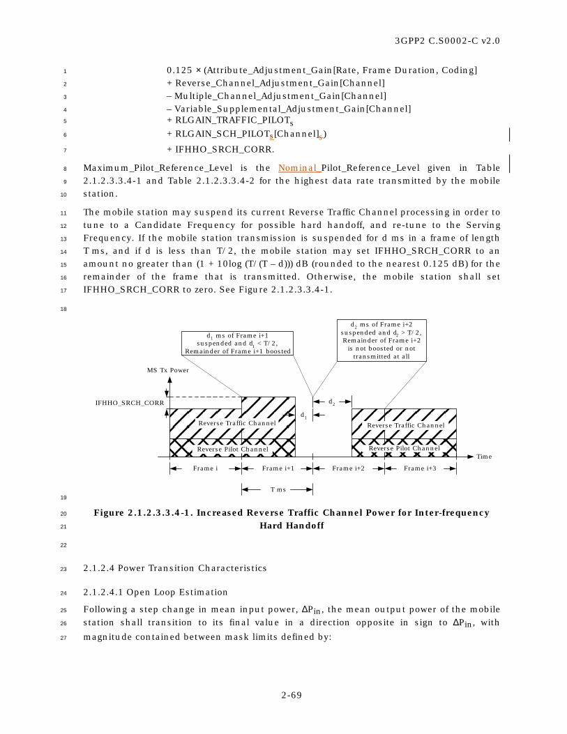
3GPP2 C.S0002-C v2.0
2-69
0.125 × (Attribute_Adjustment_Gain[Rate, Frame Duration, Coding] 1
+ Reverse_Channel_Adjustment_Gain[Channel] 2
– Multiple_Channel_Adjustment_Gain[Channel] 3
– Variable_Supplemental_Adjustment_Gain[Channel] 4
+ RLGAIN_TRAFFIC_PILOTs 5
+ RLGAIN_SCH_PILOTs[Channel]s) 6
+ IFHHO_SRCH_CORR. 7
Maximum_Pilot_Reference_Level is the Nominal_Pilot_Reference_Level given in Table 8
2.1.2.3.3.4-1 and Table 2.1.2.3.3.4-2 for the highest data rate transmitted by the mobile 9
station. 10
The mobile station may suspend its current Reverse Traffic Channel processing in order to 11
tune to a Candidate Frequency for possible hard handoff, and re-tune to the Serving 12
Frequency. If the mobile station transmission is suspended for d ms in a frame of length 13
T ms, and if d is less than T/2, the mobile station may set IFHHO_SRCH_CORR to an 14
amount no greater than (1 + 10log (T/(T – d))) dB (rounded to the nearest 0.125 dB) for the 15
remainder of the frame that is transmitted. Otherwise, the mobile station shall set 16
IFHHO_SRCH_CORR to zero. See Figure 2.1.2.3.3.4-1. 17
18
Time
Reverse Traffic Channel
Reverse Pilot Channel
d1 ms of Frame i+1suspended and d1 < T/2,
Remainder of Frame i+1 boosted
Frame i+1Frame i Frame i+2 Frame i+3
IFHHO_SRCH_CORR
d2 ms of Frame i+2suspended and d2 > T/2,Remainder of Frame i+2
is not boosted or nottransmitted at all
d1
d2
Reverse Traffic Channel
Reverse Pilot Channel
T ms
MS Tx Power
19
Figure 2.1.2.3.3.4-1. Increased Reverse Traffic Channel Power for Inter-frequency 20
Hard Handoff 21
22
2.1.2.4 Power Transition Characteristics 23
2.1.2.4.1 Open Loop Estimation 24
Following a step change in mean input power, ∆Pin, the mean output power of the mobile 25
station shall transition to its final value in a direction opposite in sign to ∆Pin, with 26
magnitude contained between mask limits defined by: 27

3GPP2 C.S0002-C v2.0
2-70
upper limit: 1
for 0 < t < 24 ms: max [1.2 × |∆Pin| × (t/24), |∆Pin| × (t/24) + 2.0 dB] + 1.5 dB,15 2
for t ≥ 24 ms: max [1.2 × |∆Pin|, |∆Pin| + 0.5 dB] + 1.5 dB; 3
lower limit: 4
for t > 0: max [0.8 × |∆Pin| × [1 – e(1.25 – t)/36] – 2.0 dB, 0] – 1 dB; 5
where t is expressed in units of milliseconds and ∆Pin is expressed in units of dB. 6
These limits shall apply for a step change ∆Pin of ±20 dB or less. The absolute value of the 7
change in mean output power due to open loop power control shall be a monotonically 8
increasing function of time. If the change in mean output power consists of discrete 9
increments, no single increment shall exceed 1.2 dB. See 2.1.2.3 for the valid range of the 10
mobile station’s mean output power. 11
2.1.2.4.2 Closed Loop Correction 12
Following the reception of a valid closed loop power control bit on the fForward pPower 13
cControl sSubchannel or the Forward cCommon pPower cControl subcChannel, the mean 14
output power of the mobile station shall be within 0.3 dB of the final value in less than 15
500 µs. For power control step sizes of 0.5 dB and 0.25 dB, the mean output power of the 16
mobile station should be within 0.15 dB of the final value in less than 500 µs. 17
2.1.2.4.3 Phase Continuity Requirements for Radio Configurations 3 through 6 18
When operating with Radio Configurations 3 through 6, the mobile station may have 19
transmitted phase discontinuities. The mobile station shall meet the requirements set 20
forth in the current version of [11]. 21
2.1.3 Modulation Characteristics 22
2.1.3.1 Reverse CDMA Channel Signals 23
Signals transmitted on the Reverse Traffic Channel (i.e., Reverse Dedicated Control 24
Channel, Reverse Fundamental Channel, Reverse Supplemental Channel, or Reverse 25
Supplemental Code Channel) are specified by radio configurations. There are six radio 26
configurations for the Reverse Traffic Channel (see Table 2.1.3.1-1). 27
A mobile station shall support operation in Radio Configuration 1, 3, or 5. A mobile station 28
may support operation on Radio Configuration 2, 4, or 6. A mobile station supporting 29
operation in Radio Configuration 2 shall support Radio Configuration 1. A mobile station 30
supporting operation in Radio Configuration 4 shall support Radio Configuration 3. A 31
mobile station supporting operation in Radio Configuration 6 shall support Radio 32
Configuration 5. 33
A mobile station shall not use Radio Configuration 1 or 2 simultaneously with Radio 34
Configuration 3, 4, 5, or 64 on the Reverse Traffic Channel. 35
15The mask limits allow for the effect of alternating closed loop power control bits.

3GPP2 C.S0002-C v2.0
2-71
If the mobile station supports the Forward Fundamental Channel with Radio 1
Configuration 1, then it shall support the Reverse Fundamental Channel with Radio 2
Configuration 1. If the mobile station supports the Forward Fundamental Channel with 3
Radio Configuration 2, then it shall support the Reverse Fundamental Channel with Radio 4
Configuration 2. If the mobile station supports the Forward Fundamental Channel with 5
Radio Configuration 3 or 4, then it shall support the Reverse Fundamental Channel with 6
Radio Configuration 3. If the mobile station supports the Forward Fundamental Channel 7
with Radio Configuration 5, then it shall support the Reverse Fundamental Channel with 8
Radio Configuration 4. 9
If the mobile station supports the Forward Fundamental Channel with Radio 10
Configuration 6 or 7, then it shall support the Reverse Fundamental Channel with Radio 11
Configuration 3 or 5. If the mobile station supports the Forward Fundamental Channel 12
with Radio Configuration 8 or 9, then it shall support the Reverse Fundamental Channel 13
with Radio Configuration 4 or 6. 14
If the mobile station supports the Forward Dedicated Control Channel with Radio 15
Configuration 3 or 4, then it shall support the Reverse Dedicated Control Channel with 16
Radio Configuration 3. If the mobile station supports the Forward Dedicated Control 17
Channel with Radio Configuration 5, then it shall support the Reverse Dedicated Control 18
Channel with Radio Configuration 4. If the mobile station supports the Forward Dedicated 19
Control Channel with Radio Configuration 6 or 7, then it shall support the Reverse 20
Dedicated Control Channel with Radio Configuration 3 or 5. If the mobile station supports 21
the Forward Dedicated Control Channel with Radio Configuration 8 or 9, then it shall 22
support the Reverse Dedicated Control Channel with Radio Configuration 4 or 6. 23
If the mobile station supports the Forward Packet Data Channel with Radio Configuration 24
10, then it shall support either the Reverse Fundamental Channel, the Reverse Dedicated 25
Control Channel, or both, with Radio Configuration 3. If the mobile station supports the 26
Forward Packet Data Channel with Radio Configuration 10, then it may support either the 27
Reverse Fundamental Channel, the Reverse Dedicated Control Channel, or both, with 28
Radio Configuration 4. If the mobile station supports the Forward Packet Data Channel 29
with Radio Configuration 10, then it shall support the reverse Acknowledgment Channel 30
and the Reverse Channel Quality Indicator Channel. 31
32

3GPP2 C.S0002-C v2.0
2-72
Table 2.1.3.1-1. Radio Configuration Characteristics for the Reverse CDMA Channel 1
Radio Config.
Associated Spreading
Rate
Data Rates, Forward Error Correction, and General Characteristics
1 1 1200, 2400, 4800, and 9600 bps data rates with R = 1/3, 64-ary orthogonal modulation
2 1 1800, 3600, 7200, and 14400 bps data rates with R = 1/2, 64-ary orthogonal modulation
3 1 1200, 1350, 1500, 2400, 2700, 4800, 9600, 19200, 38400, 76800, and 153600 bps data rates with R = 1/4, 307200 bps data rate with R = 1/2, BPSK modulation with a pilot
4 1 1800, 3600, 7200, 14400, 28800, 57600, 115200, and 230400 bps data rates with R = 1/4, BPSK modulation with a pilot
5 3 1200, 1350, 1500, 2400, 2700, 4800, 9600, 19200, 38400, 76800, and 153600 bps data rates with R = 1/4, 307200 and 614400 bps data rate with R = 1/3, BPSK modulation with a pilot
6 3 1800, 3600, 7200, 14400, 28800, 57600, 115200, 230400, and 460800 bps data rates with R = 1/4, 1036800 bps data rate with R = 1/2, BPSK modulation with a pilot
Note: For Radio Configurations 3 through 6, the Reverse Dedicated Control Channel and Reverse Fundamental Channel also allow a 9600 bps, 5 ms format.
2
2.1.3.1.1 Channel Structures 3
The structure of the code channels transmitted by a mobile station is shown in Figure 4
2.1.3.1.1-1. 5
6

3GPP2 C.S0002-C v2.0
2-73
REVERSE CDMA CHANNELfor Spreading Rates 1 and 3 (SR1 and SR3)
AccessChannel
ReverseTraffic
Channel(SR1, RC 1
or 2)
EnhancedAccess
ChannelOperation
ReverseCommonControlChannel
Operation
ReverseTraffic
ChannelOperation(RC 3 to 6)
ReverseFundamental
Channel
ReversePilot Channel
ReversePilot Channel
ReversePilot Channel
0 to 7 ReverseSupplemental
Code Channels
Enhanced AccessChannel
Reverse CommonControl Channel
0 or 1 ReverseDedicated Control
Channel
0 or 1 ReverseFundamental
Channel
0 to 2 ReverseSupplemental
Channels
0 or 1 ReversePower ControlSubchannel
0 or 1 ReverseAcknowledgment
Channel (SR1, RC 3or 4)
0 or 1 ReverseChannel Quality
Indicator Channel(SR1, RC 3 or 4)
1
Figure 2.1.3.1.1-1. Reverse CDMA Channels Received at the Base Station 2
3
2.1.3.1.1.1 Spreading Rate 1 4
The Reverse CDMA Channel consists of the channels specified in Table 2.1.3.1.1.1-1. 5
Table 2.1.3.1.1.1-1 states the maximum number of channels that can be transmitted by 6
each mobile station for each channel type. 7
8

3GPP2 C.S0002-C v2.0
2-74
Table 2.1.3.1.1.1-1. Channel Types per Mobile Station on the Reverse CDMA Channel 1
for Spreading Rate 1 2
Channel Type Maximum Number
Reverse Pilot Channel 1
Access Channel 1
Enhanced Access Channel 1
Reverse Common Control Channel 1
Reverse Dedicated Control Channel 1
Reverse Acknowledgment Channel 1
Reverse Channel Quality Indicator Channel 1
Reverse Fundamental Channel 1
Reverse Supplemental Code Channel (RC 1 and 2 only)
7
Reverse Supplemental Channel (RC 3 and 4 only)
2
3
The structure of the Access Channel for Spreading Rate 1 is shown in Figure 2.1.3.1.1.1-1. 4
The structure of the Enhanced Access Channel for Spreading Rate 1 is shown in Figure 5
2.1.3.1.1.1-2 and Figure 2.1.3.1.1.1-3. The structure of the Reverse Common Control 6
Channel for Spreading Rate 1 is shown in Figure 2.1.3.1.1.1-3. The structure of the 7
Reverse Dedicated Control Channel for Spreading Rate 1 is shown in Figure 2.1.3.1.1.1-4 8
and Figure 2.1.3.1.1.1-5. The structure of the Reverse Acknowledgment Channel is shown 9
in Figure 2.1.3.1.1.1-6. The structure of the Reverse Channel Quality Indicator Channel is 10
shown in Figure 2.1.3.1.1.1-7. 11
The Reverse Fundamental Channel and Reverse Supplemental Code Channel for Radio 12
Configuration 1 have the overall structure shown in Figure 2.1.3.1.1.1-8. The Reverse 13
Fundamental Channel and Reverse Supplemental Code Channel for Radio Configuration 2 14
have the overall structure shown in Figure 2.1.3.1.1.1-9. The Reverse Fundamental 15
Channel and Reverse Supplemental Channel for Radio Configuration 3 have the overall 16
structure shown in Figure 2.1.3.1.1.1-10. The Reverse Fundamental Channel and Reverse 17
Supplemental Channel for Radio Configuration 4 have the overall structure shown in 18
Figure 2.1.3.1.1.1-11. 19
The Reverse Pilot Channel and the rReverse pPower cControl sSubchannel are shown in 20
Figure 2.1.3.1.10.1-1. 21
The I and Q mapping for the Reverse Pilot Channel, the Enhanced Access Channel, the 22
Reverse Common Control Channel, the Reverse Acknowledgment Channel, the Reverse 23
Channel Quality Indicator Channel, and the Reverse Traffic Channel with Radio 24
Configurations 3 and 4 is shown in Figure 2.1.3.1.1.1-12. 25
26

3GPP2 C.S0002-C v2.0
2-75
I-ChannelPN Sequence
64-aryOrthogonalModulator
BlockInterleaver
(576Symbols)
RepeatedCode Symbol
307.2 kcps28.8 ksps
Long CodeGenerator(1.2288Mcps)
Long CodeMask
Add 8EncoderTail Bits
AccessChannel
Bits
88 Bits per20 ms Frame
ConvolutionalEncoder
R = 1/3, K = 9
CodeSymbol
Data Rate4.8 kbps
RepeatedCode
SymbolSymbolRepetition(2× Factor) 28.8 ksps
I
Σs(t)
cos(2πfct)
BasebandFilter
sin(2πfct)
Q ChannelGain
Signal PointMapping0 → +11 → –1
1/2 PNChipDelay
Q-ChannelPN Sequence
BasebandFilter
ChannelGain
Signal PointMapping0 → +11 → –1 +
+
1
Figure 2.1.3.1.1.1-1. Channel Structure for the Access Channel Structure for 2
Spreading Rate 1 3
4
ConvolutionalEncoder
R = 1/4, K = 9
SymbolRepetition(4× Factor)
Add 8EncoderTail Bits
BlockInterleaver
(768Symbols)
C
153.6 kspsData Rate9.6 kbps
EnhancedAccess
ChannelBits
32 Bits per5 ms Frame
Add 8-BitFrameQuality
Indicator
ModulationSymbol
5
Figure 2.1.3.1.1.1-2. Channel Structure for the Header 6
on the Enhanced Access Channel Header Sturcture for Spreading Rate 1 7
8

3GPP2 C.S0002-C v2.0
2-76
Data RateBits/Frame Bits (kbps) Factor Symbols Rate (ksps)
172 Bits/5 ms 12 38.4 1× 768 153.6360 Bits/10 ms 16 38.4 1× 1,536 153.6172 Bits/10 ms 12 19.2 2× 1,536 153.6744 Bits/20 ms 16 38.4 1× 3,072 153.6360 Bits/20 ms 16 19.2 2× 3,072 153.6172 Bits/20 ms 12 9.6 4× 3,072 153.6
ConvolutionalEncoder
R = 1/4, K = 9
SymbolRepetition
AddFrameQuality
Indicator
Add 8EncoderTail Bits
ReverseCommon Control
Channel orEnhanced Access
Channel Bits
BlockInterleaver
C
ModulationSymbol
1
Figure 2.1.3.1.1.1-3. Channel Structure for the Data on the Enhanced Access 2
Channel Data and the Reverse Common Control Channel Structure for Spreading 3
Rate 1 4
5
Data RateBits/Frame Bits (kbps) Factor Symbols Rate (ksps)
24 Bits/5 ms 16 9.6 2× 384 76.8172 Bits/20 ms 12 9.6 2× 1,536 76.8
1 to 171 Bits/20 ms 12 or 16 1.05 to 9.55 1,536 76.8
ConvolutionalEncoder
R = 1/4, K = 9
SymbolRepetition
AddFrameQuality
Indicator
Add 8EncoderTail Bits
ReverseDedicatedControlChannel
Bits
BlockInterleaver
B
ModulationSymbol
Note: If flexible data rates are supported, there can be 1 to 171 channel bits in a 20 ms frame. Symbol repetition factor iscalculated to achieve the interleaver block size of 1,536.
6
Data RateBits/Frame Bits (kbps) Symbols Rate (ksps)
24 Bits/5 ms 16 9.6 384 76.8172 Bits/20 ms 12 9.6 1,536 76.8
1 to 171 Bits/20 ms 12 or 16 1.05 to 9.55 1,536 76.8
ConvolutionalEncoder
R = 1/4, K = 9
SymbolRepetition
(2×Factor)
AddFrameQuality
Indicator
Add 8EncoderTail Bits
ReverseDedicatedControlChannel
Bits
BlockInterleaver
B
ModulationSymbol
Note: If flexible data rates are supported, there can be 1 to 171 channel bits in a 20 ms frame and the encodedsymbols will be repeated and then punctured to provide a 76.8 ksps modulation symbol rate. 7
Figure 2.1.3.1.1.1-4. Reverse Dedicated Control Channel Structure 8
for Radio Configuration 3 9
10

3GPP2 C.S0002-C v2.0
2-77
Data RateBits/Frame Bits Bits (kbps) Factor Deletion Symbols Rate (ksps)
24 Bits/5 ms 0 16 9.6 2× None 384 76.8267 Bits/20 ms 1 12 14.4 2× 8 of 24 1,536 76.8
1 to 268 Bits/20 ms 0 12 or 16 1.05 to 14.4 1,536 76.8
ReverseDedicatedControlChannel
Bits
ConvolutionalEncoder
R = 1/4, K = 9
SymbolRepetition
SymbolPuncture
BlockInterleaver
AddFrameQuality
Indicator
Add 8EncoderTail Bits
AddReserved
BitsB
ModulationSymbol
Notes: If flexible data rates are supported, there can be 1 to 268 channel bits in a 20 ms frame. Symbol repetition factor and puncturing are calculated toachieve the interleaver block size of 1,536.
1
Data RateBits/Frame Bits Bits (kbps) Deletion Symbols Rate (ksps)
24 Bits/5 ms 0 16 9.6 None 384 76.8267 Bits/20 ms 1 12 14.4 8 of 24 1,536 76.8
1 to 268 Bits/20 ms 0 12 or 16 1.05 to 14.4 1,536 76.8
ReverseDedicatedControlChannel
Bits
ConvolutionalEncoder
R = 1/4, K = 9
SymbolRepetition
(2×Factor)
SymbolPuncture
BlockInterleaver
AddFrameQuality
Indicator
Add 8EncoderTail Bits
AddReserved
BitsB
ModulationSymbol
Notes: If flexible data rates are supported, there can be 1 to 268 channel bits in a 20 ms frame and the encoded symbols will be repeated and thenpunctured to provide a 76.8 ksps modulation symbol rate.
2
Figure 2.1.3.1.1.1-5. Reverse Dedicated Control Channel Structure 3
for Radio Configuration 4 4
5
Symbol Repetition(Factor = 24)
D
ModulationSymbol
19.2 ksps
Reverse AcknowledgmentChannel Bits
(1 Bit per 1.25 ms Frame)
6
Figure 2.1.3.1.1.1-6. Reverse Acknowledgment Channel Structure 7
8
(12, 4) BlockEncoderR = 4/12
CQI Value Symbols(4 Bits per 1.25 ms Frame)
CQI Cover Symbols(3 Bits per 1.25 ms Frame)
8-SymbolWalsh Cover(76.8 ksps)
Differential CQI Symbols(1 Bit per 1.25 ms Frame)
SymbolRepetition
(Factor = 12)12
Symbolsper Frame
96Symbols
per Frame
E
ModulationSymbol
76.8 ksps
9
Figure 2.1.3.1.1.1-7. Reverse Channel Quality Indicator Channel Structure 10
11

3GPP2 C.S0002-C v2.0
2-78
I
Σs(t)
cos(2πfct + φ)
BasebandFilter
sin(2πfct + φ)
Q ChannelGain
Signal PointMapping0 → +11 → –1
1/2 PNChipDelay
I-ChannelPN Sequence
Q-ChannelPN Sequence
BasebandFilter
ChannelGain
Signal PointMapping0 → +11 → –1
DataBurst
Randomizer
64-aryOrthogonalModulator
Long CodeGenerator(1.2288Mcps)
Long CodeMask
for User m
BlockInterleaver
(576Symbols)
RepeatedCode Symbol
307.2 kcps28.8 ksps
Data RateBits/Frame Bits (kbps) Factor
16 Bits/20 ms 0 1.2 8×40 Bits/20 ms 0 2.4 4×80 Bits/20 ms 8 4.8 2×172 Bits/20 ms 12 9.6 1×
AddFrameQuality
Indicator
Add 8EncoderTail Bits
ConvolutionalEncoder
R = 1/3, K = 9
RepeatedCode
SymbolCode
SymbolSymbol
Repetition 28.8 ksps
ReverseTraffic
ChannelBits
+
+
1
Figure 2.1.3.1.1.1-8. Channel Structure for the Reverse Fundamental Channel and 2
Reverse Supplemental Code Channel Structure forwith Radio Configuration 1 3
4
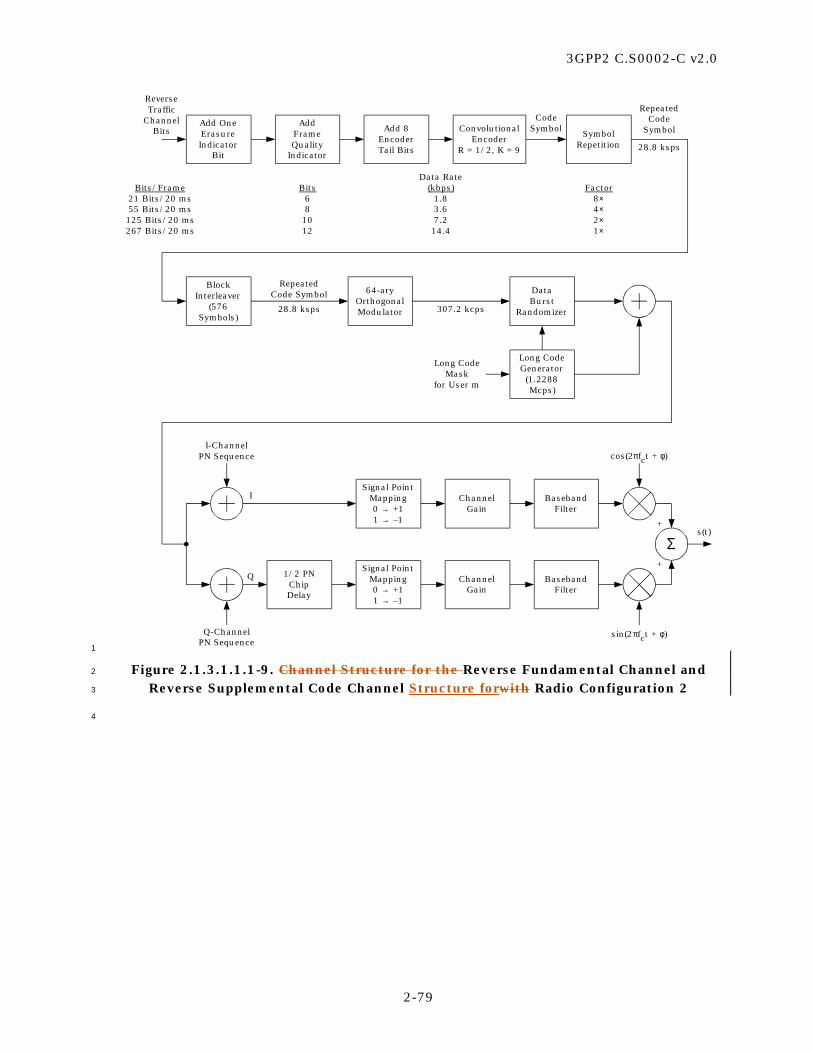
3GPP2 C.S0002-C v2.0
2-79
I
Σs(t)
cos(2πfct + φ)
BasebandFilter
sin(2πfct + φ)
Q ChannelGain
Signal PointMapping0 → +11 → –1
1/2 PNChipDelay
I-ChannelPN Sequence
Q-ChannelPN Sequence
BasebandFilter
ChannelGain
Signal PointMapping0 → +11 → –1
DataBurst
Randomizer
64-aryOrthogonalModulator
Long CodeGenerator(1.2288Mcps)
Long CodeMask
for User m
BlockInterleaver
(576Symbols)
RepeatedCode Symbol
307.2 kcps28.8 ksps
Add OneErasureIndicator
Bit
AddFrameQuality
Indicator
Add 8EncoderTail Bits
ConvolutionalEncoder
R = 1/2, K = 9
ReverseTraffic
ChannelBits
RepeatedCode
SymbolCode
SymbolSymbol
Repetition 28.8 ksps
Data RateBits/Frame Bits (kbps) Factor
21 Bits/20 ms 6 1.8 8×55 Bits/20 ms 8 3.6 4×125 Bits/20 ms 10 7.2 2×267 Bits/20 ms 12 14.4 1×
+
+
1
Figure 2.1.3.1.1.1-9. Channel Structure for the Reverse Fundamental Channel and 2
Reverse Supplemental Code Channel Structure forwith Radio Configuration 2 3
4

3GPP2 C.S0002-C v2.0
2-80
Data RateBits/Frame Bits (kbps) R Factor Deletion Symbols Rate (ksps)
24 Bits/5 ms 16 9.6 1/4 2× None 384 76.8
16 Bits/20 ms 6 1.5 1/4 16× 1 of 5 1,536 76.840 Bits/20n ms 6 2.7/n 1/4 8× 1 of 9 1,536 76.8/n80 Bits/20n ms 8 4.8/n 1/4 4× None 1,536 76.8/n172 Bits/20n ms 12 9.6/n 1/4 2× None 1,536 76.8/n
360 Bits/20n ms 16 19.2/n 1/4 1× None 1,536 76.8/n744 Bits/20n ms 16 38.4/n 1/4 1× None 3,072 153.6/n
1,512 Bits/20n ms 16 76.8/n 1/4 1× None 6,144 307.2/n3,048 Bits/20n ms 16 153.6/n 1/4 1× None 12,288 614.4/n6,120 Bits/20n ms 16 307.2/n 1/2 1× None 12,288 614.4/n
1 to 6,119 Bits/20n ms
Convolutionalor TurboEncoder
SymbolRepetition
SymbolPuncture
BlockInterleaver
AddFrameQuality
Indicator
Add 8Reserved/EncoderTail Bits
ChannelBits C
ModulationSymbol
Notes:1. n is the length of the frame in multiples of 20 ms. For 31 to 54 encoder input bits per frame, n = 1 or 2. For more than 54 encoder
input bits per frame, n = 1, 2, or 4.2. The 5 ms frame is only used for the Reverse Fundamental Channel.
3. Reverse Fundamental Channel only uses 15 to 192 encoder input bits per frame with n = 1.4. Turbo coding may be used for the Reverse Supplemental Channels with 384 or more encoder input bits per frame; otherwise, K = 9
convolutional coding is used.5. With convolutional coding, the Reserved/Encoder Tail bits provide an encoder tail. With turbo coding, the first two of these bits
are reserved bits that are encoded and the last six bits are replaced by an internally generated tail.6. If variable-rate Reverse Supplemental Channel operation, flexible reverse link data rates, or both are supported, the parameters
are determined from the specified number of channel bits per frame, the maximum assigned number of channel bits per frame forthe Reverse Fundamental Channel or the Reverse Supplemental Channel, and the specified frame quality indicator length.
- The frame quality indicator length is 16 for more than 192 encoder input bits per frame; 12 or 16 for 97 to 192 encoder inputbits per frame; 8, 12, or 16 for 55 to 96 encoder input bits per frame; and 6, 8, 12, or 16 otherwise.
- The code rate is 1/2 for more than 3,072 encoder input bits per frame; otherwise, it is 1/4. If the number of encoder input bitsper frame is less than 384, the type of encoding is convolutional; otherwise, it is the same as that of the maximum assigneddata rate for the channel.
- If the specified number of channel bits per frame is equal to the maximum assigned number of channel bits per frame and thatnumber and the specified frame quality indicator length match one of the listed cases, the symbol repetition factor and symbolpuncturing from that listed case are used. Otherwise, the symbol repetition factor and puncturing are calculated to achievethe same interleaver block size as for the maximum assigned data rate for the channel.
- If the maximum assigned data rate matches one of the data rates listed in the figure, the interleaver block size for that listeddata rate is used. Otherwise, the interleaver block size of the next higher listed data rate is used. 1
Figure 2.1.3.1.1.1-10. Reverse Fundamental Channel and Reverse Supplemental 2
Channel Structure for Radio Configuration 3 3
4

3GPP2 C.S0002-C v2.0
2-81
Data RateBits/Frame Bits Bits (kbps) R Factor Deletion Symbols Rate (ksps)
24 Bits/5 ms 0 16 9.6 1/4 2× None 384 76.8
21 Bits/20 ms 1 6 1.8 1/4 16× 8 of 24 1,536 76.855 Bits/20n ms 1 8 3.6/n 1/4 8× 8 of 24 1,536 76.8/n125 Bits/20n ms 1 10 7.2/n 1/4 4× 8 of 24 1,536 76.8/n267 Bits/20n ms 1 12 14.4/n 1/4 2× 8 of 24 1,536 76.8/n
552 Bits/20n ms 0 16 28.8/n 1/4 1× 4 of 12 1,536 76.8/n1,128 Bits/20n ms 0 16 57.6/n 1/4 1× 4 of 12 3,072 153.6/n2,280 Bits/20n ms 0 16 115.2/n 1/4 1× 4 of 12 6,144 307.2/n4,584 Bits/20n ms 0 16 230.4/n 1/4 1× 4 of 12 12,288 614.4/n
1 to 4,583 Bits/20n ms
ChannelBits
Convolutionalor TurboEncoder
SymbolRepetition
SymbolPuncture
BlockInterleaver
AddFrameQuality
Indicator
Add 8Reserved/EncoderTail Bits
AddReserved
BitsC
ModulationSymbol
Notes:1. n is the length of the frame in multiples of 20 ms. For 37 to 72 encoder input bits per frame, n = 1 or 2. For more than 72 encoder input bits per
frame, n = 1, 2, or 4.2. The 5 ms frame is only used for the Reverse Fundamental Channel.
3. Reverse Fundamental Channel only uses 15 to 288 encoder input bits per frame with n = 1.4. Turbo coding may be used for the Reverse Supplemental Channels with 576 or more encoder input bits per frame; otherwise, K = 9 convolutional
coding is used.5. With convolutional coding, the Reserved/Encoder Tail bits provide an encoder tail. With turbo coding, the first two of these bits are reserved bits that
are encoded and the last six bits are replaced by an internally generated tail.6. If variable-rate Reverse Supplemental Channel operation, flexible reverse link data rates, or both are supported, the parameters are determined
from the specified number of channel bits per frame, the maximum assigned number of channel bits per frame for the Reverse FundamentalChannel or the Reverse Supplemental Channel, and the specified frame quality indicator length.
- When the number of channel bits per frame is 21, 55, 125, or 267 and the corresponding number of frame quality indicator bits is 6, 8, 10, and12, an initial reserved bit is used; otherwise, no initial reserved bits are used.
- The frame quality indicator length is 16 for more than 288 encoder input bits per frame; 12 or 16 for 145 to 288 encoder input bits per frame;10, 12, or 16 for 73 to 144 encoder input bits per frame; 8, 10, 12, or 16 for 37 to 72 encoder input bits per frame; and 6, 8, 10, 12, or 16otherwise.
- If the number of encoder input bits per frame is less than 576, the type of encoding is convolutional; otherwise, it is the same as that of themaximum assigned data rate for the channel.
- If the specified number of channel bits per frame is equal to the maximum assigned number of channel bits per frame and that number andthe specified frame quality indicator length match one of the listed cases, the symbol repetition factor and symbol puncturing from that listedcase are used. Otherwise, the symbol repetition factor and puncturing are calculated to achieve the same interleaver block size as for themaximum assigned data rate for the channel.
- If the maximum assigned data rate matches one of the data rates listed in the figure, the interleaver block size for that listed data rate is used.Otherwise, the interleaver block size of the next higher listed data rate is used.
- If ERAM is disabled, the code rate is 1/4. If ERAM is enabled, the code rate of the turbo encoder shall be selected as follows:R = 1/3, if 8/3 < N/I < 3; R = 1/4, if 3 < N/I < 4 or N/I = 8/3; R = 1/5, if N/I > 4where I denotes the number of encoder input bits per frame, and N denotes the interleaver block size. 1
Figure 2.1.3.1.1.1-11. Reverse Fundamental Channel and Reverse Supplemental 2
Channel Structure for Radio Configuration 4 3
4
3GPP2 C.S0002-C v2.0
2-82
1
RelativeGain
RelativeGain
RelativeGain
++
Notes :1. Binary signals are represented with ±1 values
with the mapping +1 for ‘0’ and –1 for ‘1’.Unused channels and gated-off symbols arerepresented with zero values.
2. When the Reverse Common Control Channel orEnhanced Access Channel is used, the onlyadditional channel is the Reverse Pilot Channel.
3. All of the pre-baseband-filter operations occurat the chip rate of 1.2288 Mcps.
4. If the Reverse Fundamental Channel is assigned, the Reverse Channel Quality Indicator Channel shall be transmitted on the I-channel. Otherwise, the Reverse Channel Quality Indicator Channel shall be transmitted on the Q-channel.
Complex Multiplier
–
+
+
+
BasebandFilter
BasebandFilter
cos(2πfct)
sin(2πfct)
GainWalsh Cover W816
Walsh Cover W416
Walsh Cover W12 or W2
4
for Reverse Supplemental Channel 1,W2
8 for Reverse Common ControlChannel and Enhanced Access
Channel
B
C
C
ReversePilot
Channel
ReverseSupplemental
Channel 1, ReverseCommon Control
Channel, or EnhancedAccess Channel
ReverseFundamental
Channel
ReverseDedicated
Control Channel
Σ
Σ
Σ
Decimatorby Factor
of 2
Walsh CoverW1
2
C
A
RelativeGain
+
ReverseSupplemental
Channel 2
Walsh Cover W24 or W6
8
s(t)
1-ChipDelay
Long CodeGenerator
(1.2288 Mcps)
Q-ChannelPN SequenceI-Channel
PN Sequence
Long CodeMask
I-ChannelData
Q-ChannelData
+
+Σ
Σ+
+
RelativeGain
Walsh Cover W1664
DReverse
AcknowledgmentChannel
RelativeGain
Walsh Cover W1216
E
ReverseChannel Quality
IndicatorChannel
+ +
RelativeGain
Walsh Cover W1216
EReverse
Channel QualityIndicatorChannel
+
2
Figure 2.1.3.1.1.1-12. I and Q Mapping for Reverse Pilot Channel, Enhanced Access 3
Channel, Reverse Common Control Channel, Reverse Acknowledgment Channel, 4
Reverse Channel Quality Indicator Channel, and Reverse Traffic Channel with Radio 5
Configurations 3 and 4 6
7
2.1.3.1.1.2 Spreading Rate 3 8
The Reverse CDMA Channel consists of the channels specified in Table 2.1.3.1.1.2-1. 9
Table 2.1.3.1.1.2-1 states the maximum number of channels that can be transmitted by 10
each mobile station for each channel type. 11
12

3GPP2 C.S0002-C v2.0
2-83
Table 2.1.3.1.1.2-1. Channel Types per Mobile Station on the Reverse CDMA Channel 1
for Spreading Rate 3 2
Channel Type Maximum Number
Reverse Pilot Channel 1
Enhanced Access Channel 1
Reverse Common Control Channel 1
Reverse Dedicated Control Channel 1
Reverse Fundamental Channel 1
Reverse Supplemental Channel 2
3
The structure of the Enhanced Access Channel for Spreading Rate 3 is shown in Figure 4
2.1.3.1.1.2-1 and Figure 2.1.3.1.1.2-2. The structure of the Reverse Common Control 5
Channel for Spreading Rate 3 is shown in Figure 2.1.3.1.1.2-2. The structure of the 6
Reverse Dedicated Control Channel for Spreading Rate 3 is shown in Figure 2.1.3.1.1.2-3 7
and Figure 2.1.3.1.1.2-4. 8
The Reverse Fundamental Channel and Reverse Supplemental Channel for Radio 9
Configuration 5 have the overall structure shown in Figure 2.1.3.1.1.2-5. The Reverse 10
Fundamental Channel and Reverse Supplemental Channel for Radio Configuration 6 has 11
the overall structure shown in Figure 2.1.3.1.1.2-6. 12
The Reverse Pilot Channel and the rReverse pPower cControl sSubchannel are shown in 13
Figure 2.1.3.1.10.1-1. 14
The I and Q mapping for Spreading Rate 3 is shown in Figure 2.1.3.1.1.2-7. 15
16
ConvolutionalEncoder
R = 1/4, K = 9
SymbolRepetition(4× Factor)
Add 8EncoderTail Bits
BlockInterleaver
(768Symbols)
C
153.6 kspsData Rate9.6 kbps
EnhancedAccess
ChannelBits
32 Bits per5 ms Frame
Add 8-BitFrameQuality
Indicator
ModulationSymbol
17
Figure 2.1.3.1.1.2-1. Channel Structure for the Header on the Enhanced Access 18
Channel Header Structure for Spreading Rate 3 19
20

3GPP2 C.S0002-C v2.0
2-84
Data RateBits/Frame Bits (kbps) Factor Symbols Rate (ksps)
172 Bits/5 ms 12 38.4 1× 768 153.6360 Bits/10 ms 16 38.4 1× 1,536 153.6172 Bits/10 ms 12 19.2 2× 1,536 153.6744 Bits/20 ms 16 38.4 1× 3,072 153.6360 Bits/20 ms 16 19.2 2× 3,072 153.6172 Bits/20 ms 12 9.6 4× 3,072 153.6
ConvolutionalEncoder
R = 1/4, K = 9
SymbolRepetition
AddFrameQuality
Indicator
Add 8EncoderTail Bits
ReverseCommon Control
Channel orEnhanced Access
Channel Bits
BlockInterleaver
C
ModulationSymbol
1
Figure 2.1.3.1.1.2-2. Channel Structure for the Data on the Enhanced Access 2
Channel Data and the Reverse Common Control Channel Structure for Spreading 3
Rate 3 4
5
Data RateBits/Frame Bits (kbps) Factor Symbols Rate (ksps)
24 Bits/5 ms 16 9.6 2× 384 76.8172 Bits/20 ms 12 9.6 2× 1,536 76.8
1 to 171 Bits/20 ms 12 or 16 1.05 to 9.55 1,536 76.8
ConvolutionalEncoder
R = 1/4, K = 9
SymbolRepetition
AddFrameQuality
Indicator
Add 8EncoderTail Bits
ReverseDedicatedControlChannel
Bits
BlockInterleaver
B
ModulationSymbol
Note: If flexible data rates are supported, there can be 1 to 171 channel bits in a 20 ms frame. Symbol repetition factor iscalculated to achieve the interleaver block size of 1,536.
6
Data RateBits/Frame Bits (kbps) Symbols Rate (ksps)
24 Bits/5 ms 16 9.6 384 76.8172 Bits/20 ms 12 9.6 1,536 76.8
1 to 171 Bits/20 ms12 or 16 1.05 to 9.55 1,536 76.8
ConvolutionalEncoder
R = 1/4, K = 9
SymbolRepetition
(2×Factor)
AddFrameQuality
Indicator
Add 8EncoderTail Bits
ReverseDedicatedControlChannel
Bits
BlockInterleaver
B
ModulationSymbol
Note: If flexible data rates are supported, there can be 1 to 171 channel bits in a 20 ms frame and the encodedsymbols will be repeated then punctured to provide a 76.8 ksps modulation symbol rate. 7
Figure 2.1.3.1.1.2-3. Reverse Dedicated Control Channel Structure 8
for Radio Configuration 5 9
10

3GPP2 C.S0002-C v2.0
2-85
Data RateBits/Frame Bits Bits (kbps) Factor Deletion Symbols Rate (ksps)
24 Bits/5 ms 0 16 9.6 2× None 384 76.8267 Bits/20 ms 1 12 14.4 2× 8 of 24 1,536 76.8
1 to 268 Bits/20 ms 0 12 or 16 1.05 to 14.4 1,536 76.8
ReverseDedicatedControlChannel
Bits
ConvolutionalEncoder
R = 1/4, K = 9
SymbolRepetition
SymbolPuncture
BlockInterleaver
AddFrameQuality
Indicator
Add 8EncoderTail Bits
AddReserved
BitsB
ModulationSymbol
Notes: If flexible data rates are supported, there can be 1 to 268 channel bits in a 20 ms frame. Symbol repetition factor and puncturing are calculated toachieve the interleaver block size of 1,536.
1
Data RateBits/Frame Bits Bits Rate (kbps) Deletion Symbols Rate (ksps)
24 Bits/5 ms 0 16 9.6 None 384 76.8267 Bits/20 ms 1 12 14.4 8 of 24 1,536 76.8
1 to 268 Bits/20 ms 0 12 or 16 1.05 to 14.4 1,536 76.8
ReverseDedicatedControlChannel
Bits
ConvolutionalEncoder
R = 1/4, K = 9
SymbolRepetition
(2×Factor)
SymbolPuncture
BlockInterleaver
AddFrameQuality
Indicator
Add 8EncoderTail Bits
AddReserved
BitsB
ModulationSymbol
Note: If flexible data rates are supported, there can be 1 to 268 channel bits in a 20 ms frame and the encoded symbols will be additionally repeatedand then punctured to provide a 76.8 ksps modulation symbol rate. 2
Figure 2.1.3.1.1.2-4. Reverse Dedicated Control Channel Structure 3
for Radio Configuration 6 4
5

3GPP2 C.S0002-C v2.0
2-86
Convolutionalor TurboEncoder
SymbolRepetition
SymbolPuncture
BlockInterleaver
AddFrameQuality
Indicator
Add 8Reserved/EncoderTail Bits
ChannelBits
C
ModulationSymbol
Data RateBits/Frame Bits (kbps) R Factor Deletion Symbols Rate (ksps)
24 Bits/5 ms 16 9.6 1/4 2× None 384 76.8
16 Bits/20 ms 6 1.5 1/4 16× 1 of 5 1,536 76.840 Bits/20n ms 6 2.7/n 1/4 8× 1 of 9 1,536 76.8/n80 Bits/20n ms 8 4.8/n 1/4 4× None 1,536 76.8/n
172 Bits/20n ms 12 9.6/n 1/4 2× None 1,536 76.8/n
360 Bits/20n ms 16 19.2/n 1/4 1× None 1,536 76.8/n744 Bits/20n ms 16 38.4/n 1/4 1× None 3,072 153.6/n
1,512 Bits/20n ms 16 76.8/n 1/4 1× None 6,144 307.2/n3,048 Bits/20n ms 16 153.6/n 1/4 1× None 12,288 614.4/n6,120 Bits/20n ms 16 307.2/n 1/3 1× None 18,432 921.6/n12,264 Bits/20n ms 16 614.4/n 1/3 1× None 36,864 1,843.2/n
1 to 12,263 Bits/20n ms
Notes:1. n is the length of the frame in multiples of 20 ms. For 31 to 54 encoder input bits per frame, n = 1 or 2. For more than 54 encoder
input bits per frame, n = 1, 2, or 4.2. The 5 ms frame is only used for the Reverse Fundamental Channel,
3. Reverse Fundamental Channel only uses from 15 to 192 encoder input bits per frame with n = 1.4. Turbo coding may be used for the Reverse Supplemental Channels with 384 or more encoder input bits per frame; otherwise, K = 9
convolutional coding is used.5. With convolutional coding, the Reserved/Encoder Tail bits provide an encoder tail. With turbo coding, the first two of these bits
are reserved bits that are encoded and the last six bits are replaced by an internally generated tail.6. If variable-rate Reverse Supplemental Channel operation, flexible reverse link data rates, or both are supported, the parameters
are determined from the specified number of channel bits per frame, the maximum assigned number of channel bits per frame forthe Reverse Fundamental Channel or the Reverse Supplemental Channel, and the specified frame quality indicator length.
- The frame quality indicator length is 16 for more than 192 encoder input bits per frame; 12 or 16 for 97 to 192 encoder inputbits per frame; 8, 12, or 16 for 55 to 96 encoder input bits per frame; and 6, 8, 12, or 16 otherwise.
- The code rate is 1/3 for more than 3,072 encoder input bits per frame; otherwise, it is 1/4. If the number of encoder input bitsper frame is less than 384, the type of encoding is convolutional; otherwise, it is the same as that of the maximum assigneddata rate for the channel.
- If the specified number of channel bits per frame is equal to the maximum assigned number of channel bits per frame andthat number and the specified frame quality indicator length match one of the listed cases, the symbol repetition factor andsymbol puncturing from that listed case are used. Otherwise, the symbol repetition factor and puncturing are calculated toachieve the same interleaver block size as for the maximum assigned data rate for the channel.
- If the maximum assigned data rate matches one of the data rates listed in the figure, the interleaver block size for that listeddata rate is used. Otherwise, the interleaver block size of the next higher listed data rate is used. 1
Figure 2.1.3.1.1.2-5. Reverse Fundamental Channel and Reverse Supplemental 2
Channel Structure for Radio Configuration 5 3
4

3GPP2 C.S0002-C v2.0
2-87
ChannelBits
Convolutionalor TurboEncoder
SymbolRepetition
SymbolPuncture
BlockInterleaver
AddFrameQuality
Indicator
Add 8Reserved/EncoderTail Bits
AddReserved
BitsC
ModulationSymbol
Data RateBits/Frame Bits Bits (kbps) R Factor Deletion Symbols Rate (ksps)
24 Bits/5 ms 0 16 9.6 1/4 2× None 384 76.8
21 Bits/20 ms 1 6 1.8 1/4 16× 8 of 24 1,536 76.855 Bits/20n ms 1 8 3.6/n 1/4 8× 8 of 24 1,536 76.8/n125 Bits/20n ms 1 10 7.2/n 1/4 4× 8 of 24 1,536 76.8/n267 Bits/20n ms 1 12 14.4/n 1/4 2× 8 of 24 1,536 76.8/n
552 Bits/20n ms 0 16 28.8/n 1/4 1× None 2,304 115.2/n1,128 Bits/20n ms 0 16 57.6/n 1/4 1× None 4,608 230.4/n2,280 Bits/20n ms 0 16 115.2/n 1/4 1× None 9,216 460.8/n4,584 Bits/20n ms 0 16 230.4/n 1/4 1× None 18,432 921.6/n9,192 Bits/20n ms 0 16 460.8/n 1/4 1× None 36,864 1,843.2/n20,712 Bits/20n ms 0 16 1,036.8/n 1/2 1× 2 of 18 36,864 1,843.2/n
1 to 20,711 Bits/20n ms
Notes:1. n is the length of the frame in multiples of 20 ms. For 37 to 72 encoder input bits per frame, n = 1 or 2. For more than 72 encoder input bits per
frame, n = 1, 2, or 4.2. The 5 ms frame is only used for the Reverse Fundamental Channel.
3. Reverse Fundamental Channel only uses from 15 to 288 encoder input bits per frame with n = 1.4. Turbo coding may be used for the Reverse Supplemental Channels with 576 or more encoder input bits per frame; otherwise, K = 9 convolutional
coding is used.5. With convolutional coding, the Reserved/Encoder Tail bits provide an encoder tail. With turbo coding, the first two of these bits are reserved bits
that are encoded and the last six bits are replaced by an internally generated tail.6. If variable-rate Reverse Supplemental Channel operation, flexible reverse link data rates, or both are supported, the parameters are determined
from the specified number of channel bits per frame, the maximum assigned number of channel bits per frame for the Reverse FundamentalChannel or the Reverse Supplemental Channel, and the specified frame quality indicator length.
- When the number of channel bits per frame is 21, 55, 125, or 267 and the corresponding frame quality indicator length is 6, 8, 10, and 12, aninitial reserved bit is used; otherwise, no initial reserved bits are used.
- The frame quality indicator length is 16 for more than 288 encoder input bits per frame; 12 or 16 for 145 to 288 encoder input bits per frame;10, 12, or 16 for 73 to 144 encoder input bits per frame; 8, 10, 12, or 16 for 37 to 72 encoder input bits per frame; and 6, 8, 10, 12, or 16otherwise.
- The code rate is 1/2 for more than 9216 encoder input bits; otherwise, it is 1/4. If the number of encoder input bits per frame is less than 576,the type of encoding is convolutional; otherwise, it is the same as that of the maximum assigned data rate for the channel.
- If the specified number of channel bits per frame is equal to the maximum assigned number of channel bits per frame and that number andthe specified frame quality indicator length match one of the listed cases, the symbol repetition factor and symbol puncturing from that listedcase are used. Otherwise, the symbol repetition factor and puncturing are calculated to achieve the same interleaver block size as for themaximum assigned data rate for the channel.
- If the maximum assigned data rate matches one of the data rates listed in the figure, the interleaver block size for that listed data rate is used.Otherwise, the interleaver block size of the next higher listed data rate is used. 1
Figure 2.1.3.1.1.2-6. Reverse Fundamental Channel and Reverse Supplemental 2
Channel Structure for Radio Configuration 6 3
4

3GPP2 C.S0002-C v2.0
2-88
+
+
RelativeGain
RelativeGain
RelativeGain
+
+
Notes :1. Binary signals are represented with ±1 values
with the mapping +1 for ‘0’ and –1 for ‘1’.Unused channels and gated-off symbols arerepresented with zero values.
2. When the Reverse Common Control Channel orEnhanced Access Channel is used, the onlyadditional channel is the Reverse Pilot Channel.
3. All of the pre-baseband-filter operations occurat the chip rate of 3.6864 Mcps.
Complex Multiplier
–
+
+
+
BasebandFilter
BasebandFilter
cos(2πfct)
sin(2πfct)
GainWalsh Cover(+ + + + + + + + – – – – – – – – )
Walsh Cover(+ + + + – – – – + + + + – – – – )
Walsh Cover(+ – ) or (+ + – – )
for Reverse Supplemental Channel 1(+ + – – + + – – )
for Reverse Common Control Channeland Enhanced Access Channel
B
C
C
ReversePilot
Channel
ReverseSupplemental
Channel 1, ReverseCommon Control
Channel, or EnhancedAccess Channel
ReverseFundamental
Channel
ReverseDedicated
Control Channel
Σ
Σ
Σ
Σ
Decimatorby Factor
of 2
Walsh Cover(+ – )
C
A
RelativeGain
+
ReverseSupplemental
Channel 2
Walsh Cover(+ + – – ) or (+ + – – – – + +)
s(t)
1-ChipDelay
Long CodeGenerator
(3.6864 Mcps)
Q-ChannelPN Sequence
I-ChannelPN Sequence
Long CodeMask
I-ChannelData
Q-ChannelData
Σ+
+
1
Figure 2.1.3.1.1.2-7. I and Q Mapping for Spreading Rate 3 2
3
2.1.3.1.2 Modulation Parameters 4
2.1.3.1.2.1 Spreading Rate 1 5
The modulation parameters for the Reverse CDMA Channel operating in Spreading Rate 1 6
are shown in Table 2.1.3.1.2.1-1 through Table 2.1.3.1.2.1-16. 7
8

3GPP2 C.S0002-C v2.0
2-89
Table 2.1.3.1.2.1-1. Access Channel Modulation Parameters for Spreading Rate 1 1
Data Rate (bps)
Parameter 4,800 Units
PN Chip Rate 1.2288 Mcps
Code Rate 1/3 bits/code symbol
Code Symbol Repetition 2 repeated code symbols/code symbol
Repeated Code Symbol Rate 28,800 sps
Modulation 6 repeated code symbols/modulation symbol
Modulation Symbol Rate 4800 sps
Walsh Chip Rate 307.20 kcps
Modulation Symbol Duration
208.33 µs
PN Chips/Repeated Code Symbol
42.67 PN chips/repeated code symbol
PN Chips/Modulation Symbol
256 PN chips/modulation symbol
Transmit Duty Cycle 100.0 %
PN Chips/Walsh Chip 4 PN chips/Walsh chip
2

3GPP2 C.S0002-C v2.0
2-90
Table 2.1.3.1.2.1-2. Enhanced Access Channel Modulation Parameters 1
for Spreading Rate 1 2
Data Rate (bps)
Parameter 9,600 19,200 38,400 Units
PN Chip Rate 1.2288 1.2288 1.2288 Mcps
Code Rate 1/4 1/4 1/4 bits/code symbol
Code Symbol Repetition
4 2 1 repeated code symbols/code symbol
Modulation Symbol Rate
153,600 153,600 153,600 sps
Walsh Length 8 8 8 PN chips
Number of Walsh Function Repetitions per Modulation Symbol
1 1 1 Walsh functions/ modulation symbol
Transmit Duty Cycle 100.0 100.0 100.0 %
Processing Gain 128 64 32 PN chips/bit
Note: The Enhanced Access header uses the 9600 bps data rate only, while the Enhanced Access data uses 9600, 19200, and 38400 bps data rates.
3
Table 2.1.3.1.2.1-3. Reverse Common Control Channel Modulation Parameters 4
for Spreading Rate 1 5
Data Rate (bps)
Parameter 9,600 19,200 38,400 Units
PN Chip Rate 1.2288 1.2288 1.2288 Mcps
Code Rate 1/4 1/4 1/4 bits/code symbol
Code Symbol Repetition
4 2 1 repeated code symbols/code symbol
Modulation Symbol Rate
153,600 153,600 153,600 sps
Walsh Length 8 8 8 PN chips
Number of Walsh Function Repetitions per Modulation Symbol
1 1 1 Walsh functions/ modulation symbol
Transmit Duty Cycle 100.0 100.0 100.0 %
Processing Gain 128 64 32 PN chips/bit
6

3GPP2 C.S0002-C v2.0
2-91
Table 2.1.3.1.2.1-4. Reverse Dedicated Control Channel Modulation Parameters 1
for Radio Configuration 3 2
Data Rate (bps)
Parameter 9,600 Units
PN Chip Rate 1.2288 Mcps
Code Rate 1/4 bits/code symbol
Code Symbol Repetition 2 repeated code symbols/code symbol
Modulation Symbol Rate 76,800 sps
Walsh Length 16 PN chips
Number of Walsh Function Repetitions per Modulation Symbol
1 Walsh functions/ modulation symbol
Transmit Duty Cycle 100.0 %
Processing Gain 128 PN chips/bit
Note: If flexible data rates are supported, repetition and puncturing can be used to support data rates not specified in this table.
3

3GPP2 C.S0002-C v2.0
2-92
Table 2.1.3.1.2.1-5. Reverse Dedicated Control Channel Modulation Parameters 1
for Radio Configuration 4 2
Data Rate (bps)
Parameter 9,600 14,400 Units
PN Chip Rate 1.2288 1.2288 Mcps
Code Rate 1/4 1/4 bits/code symbol
Code Symbol Repetition 2 2 repeated code symbols/code symbol
Puncturing Rate 1 16/24 modulation symbols/repeated code symbol
Modulation Symbol Rate 76,800 76,800 sps
Walsh Length 16 16 PN chips
Number of Walsh Function Repetitions per Modulation Symbol
1 1 Walsh functions/ modulation symbol
Transmit Duty Cycle 100.0 100.0 %
Processing Gain 128 85.33 PN chips/bit
Notes:
1. The 9600 bps data rate is used for 5 ms frames and the 14400 bps data rate is used for 20 ms frames.
2. If flexible data rates are supported, repetition and puncturing can be used to support data rates not specified in this table.
3

3GPP2 C.S0002-C v2.0
2-93
Table 2.1.3.1.2.1-6. Reverse Acknowledgment Channel Modulation Parameters 1
Data Rate (bps)
Parameter 800 Units
PN Chip Rate 1.2288 Mcps
Code Rate 1/1 bits/code symbol
Code Symbol Repetition 24 repeated code symbols/code symbol
Modulation Symbol Rate 19,200 sps
Walsh Length 64 PN chips
Number of Walsh Function Repetitions per Modulation Symbol
1 Walsh functions/ modulation symbol
Processing Gain 1,536 PN chips/bit
Note: The code symbol repetition and processing gain are multiplied by a factor of 1, 2, or 4, and the data rate is divided by the same factor (see [3]).
2
Table 2.1.3.1.2.1-7. Reverse Channel Quality Indicator Channel Modulation 3
Parameters 4
Data Rate (bps)
Parameter 800 3,200 Units
PN Chip Rate 1.2288 1.2288 Mcps
Code Rate 1/1 4/12 bits/code symbol
Code Symbol Repetition 12 1 repeated code symbols/code symbol
Modulation Symbol Rate 76,800 76,800 sps
Walsh Length 16 16 PN chips
Number of Walsh Function Repetitions per Modulation Symbol
1 1 Walsh functions/ modulation symbol
Processing Gain 1,536 384 PN chips/bit
Note: The code symbol repetition and processing gain is actually multiplied by a factor of 1, 2, or 4, and the data rate is divided by the same factor (see [3]).
5

3GPP2 C.S0002-C v2.0
2-94
Table 2.1.3.1.2.1-8. Reverse Fundamental Channel and Reverse Supplemental Code 1
Channel Modulation Parameters for Radio Configuration 1 2
Data Rate (bps)
Parameter 9,600 4,800 2,400 1,200 Units
PN Chip Rate 1.2288 1.2288 1.2288 1.2288 Mcps
Code Rate 1/3 1/3 1/3 1/3 bits/code symbol
Code Symbol Repetition 1 2 4 8 repeated code symbols/code symbol
Repeated Code Symbol Rate
28,800 28,800 28,800 28,800 sps
Modulation 6 6 6 6 repeated code symbols/modulation symbol
Modulation Symbol Rate 4,800 4,800 4,800 4,800 sps
Walsh Chip Rate 307.20 307.20 307.20 307.20 kcps
Modulation Symbol Duration
208.33 208.33 208.33 208.33 µs
PN Chips/Repeated Code Symbol
42.67 42.67 42.67 42.67 PN chips/repeated code symbol
PN Chips/Modulation Symbol
256 256 256 256 PN chips/modulation symbol
PN Chips/Walsh Chip 4 4 4 4 PN chips/Walsh chip
Transmit Duty Cycle 100.0 50.0 25.0 12.5 %
Processing Gain 128 128 128 128 PN chips/bit
Note: The 1200, 2400, and 4800 bps data rates are applicable to the Reverse Fundamental Channel only.
3

3GPP2 C.S0002-C v2.0
2-95
Table 2.1.3.1.2.1-9. Reverse Fundamental Channel and Reverse Supplemental Code 1
Channel Modulation Parameters for Radio Configuration 2 2
Data Rate (bps)
Parameter 14,400 7,200 3,600 1,800 Units
PN Chip Rate 1.2288 1.2288 1.2288 1.2288 Mcps
Code Rate 1/2 1/2 1/2 1/2 bits/code symbol
Code Symbol Repetition 1 2 4 8 repeated code symbols/code symbol
Repeated Code Symbol Rate
28,800 28,800 28,800 28,800 sps
Modulation 6 6 6 6 repeated code symbols/modulation symbol
Modulation Symbol Rate 4,800 4,800 4,800 4,800 sps
Walsh Chip Rate 307.20 307.20 307.20 307.20 kcps
Modulation Symbol Duration
208.33 208.33 208.33 208.33 µs
PN Chips/Repeated Code Symbol
42.67 42.67 42.67 42.67 PN chips/repeated code symbol
PN Chips/Modulation Symbol
256 256 256 256 PN chips/modulation symbol
PN Chips/Walsh Chip 4 4 4 4 PN chips/Walsh chip
Transmit Duty Cycle 100.0 50.0 25.0 12.5 %
Processing Gain 85.33 85.33 85.33 85.33 PN chips/bit
Note: The 1800, 3600, and 7200 bps data rates are applicable to the Reverse Fundamental Channel only.
3

3GPP2 C.S0002-C v2.0
2-96
Table 2.1.3.1.2.1-10. Reverse Fundamental Channel and Reverse Supplemental 1
Channel Modulation Parameters for 20 ms Frames for Radio Configuration 3 2
Data Rate (bps)
Parameter 9,600 ×××× N 4,800 2,700 1,500 Units
PN Chip Rate 1.2288 1.2288 1.2288 1.2288 Mcps
Code Rate 1/4 (N < 32) 1/2 (N = 32)
1/4 1/4 1/4 bits/code symbol
Code Symbol Repetition
2 (N = 1) 1 (N > 1)
4 8 16 repeated code symbols/code symbol
Puncturing Rate 1 1 8/9 4/5 interleaver symbols/repeated code symbol
Modulation Symbol Rate
76,800 (N ≤ 2) 38,400 × N (N = 4 or 8)
614,400 (N ≥ 16)
76,800 76,800 76,800 sps
Walsh Length For Reverse Fundamental Channel: 16 For Reverse
Supplemental Channel:
8, 4, or 2 (N ≤ 4) 4 or 2 (N = 8)
2 (N ≥ 16)
16 (Reverse Fundamental Channel) 8, 4, or 2 (Reverse Supplemental
Channel)
PN chips
Number of Walsh Function Repetitions per Modulation Symbol
For Reverse Fundamental Channel: 1 For Reverse
Supplemental Channel:
2, 4, or 8 (N ≤ 2) 1, 2, or 4 (N = 4)
1 or 2 (N = 8) 1 (N ≥ 16)
1 (Reverse Fundamental Channel) 2, 4, or 8 (Reverse Supplemental
Channel)
Walsh functions/ modulation symbol
Transmit Duty Cycle
100.0 100.0 100.0 100.0 or 50.0
%
Processing Gain 128/N 256 455.1 819.2 PN chips/bit Notes:
1. N = 1, 2, 4, 8, 16, or 32, which yields data rates of 9600, 19200, 38400, 76800, 153600, or 307200 bps, respectively.
2. If variable-rate Reverse Supplemental Channel operation, flexible reverse link data rates, or both are supported, the parameters are determined from the specified number of channel bits per frame, the maximum assigned number of channel bits per frame for the Reverse Fundamental Channel or the Reverse Supplemental Channel, and the specified frame quality indicator length.
3. 3. The 50% transmit duty cycle at 1500 bps data rate corresponds to the Reverse Fundamental Channel gating.
3GPP2 C.S0002-C v2.0
2-97
Table 2.1.3.1.2.1-11. Reverse Supplemental Channel Modulation Parameters for 40 1
ms Frames for Radio Configuration 3 2
Data Rate (bps)
Parameter 9,600 ×××× N 4,800 2,400 1,350 Units
PN Chip Rate 1.2288 1.2288 1.2288 1.2288 Mcps
Code Rate 1/4 (N < 16) 1/2 (N = 16)
1/4 1/4 1/4 bits/code symbol
Code Symbol Repetition
1 2 4 8 repeated code symbols/code symbol
Puncturing Rate 1 1 1 8/9 interleaver symbols/ repeated code symbol
Modulation Symbol Rate
38,400 × N (N < 8) 307,200 (N ≥ 8)
38,400 38,400 38,400 sps
Walsh Length 8, 4, or 2 (N < 8) 4 or 2 (N ≥ 8)
8, 4, or 2 8, 4, or 2 8, 4, or 2 PN chips
Number of Walsh Function Repetitions per Modulation Symbol
4, 8, or 16 (N = 1) 2, 4, or 8 (N = 2) 1, 2, or 4 (N = 4)
1 or 2 (N ≥ 8)
4, 8, or 16 4, 8, or 16
4, 8, or 16 Walsh functions/ modulation symbol
Transmit Duty Cycle
100.0 100.0 100.0 100.0 %
Processing Gain 128/N 256 512 910.22 PN chips/bit
Notes:
1. N = 1, 2, 4, 8, or 16, which yields data rates of 9600, 19200, 38400, 76800, or 153600
bps, respectively.
2. If variable-rate Reverse Supplemental Channel operation, flexible reverse link data rates,
or both are supported, the parameters are determined from the specified number of
channel bits per frame, the maximum assigned number of channel bits per frame for the
Reverse Supplemental Channel, and the specified frame quality indicator length.
3

3GPP2 C.S0002-C v2.0
2-98
Table 2.1.3.1.2.1-12. Reverse Supplemental Channel Modulation Parameters for 1
80 ms Frames for Radio Configuration 3 2
Data Rate (bps)
Parameter 9,600 ×××× N 4,800 2,400 1,200 Units
PN Chip Rate 1.2288 1.2288 1.2288 1.2288 Mcps
Code Rate 1/4 (N < 8)
1/2 (N = 8)
1/4 1/4 1/4 bits/code symbol
Code Symbol
Repetition
1 1 2 4 repeated code
symbols/code
symbol
Modulation
Symbol Rate
38,400 × N (N < 4)
153,600 (N ≥ 4)
19,200 19,200 19,200 sps
Walsh Length 8, 4, or 2 8, 4, or 2 8, 4, or 2 8, 4, or 2 PN chips
Number of Walsh
Function
Repetitions per
Modulation
Symbol
4, 8, or 16 (N = 1)
2, 4, or 8 (N = 2)
1, 2, or 4 (N ≥ 4)
8, 16, or
32
8, 16, or
32
8, 16, or
32
Walsh functions/
modulation symbol
Transmit Duty
Cycle
100.0 100.0 100.0 100.0 %
Processing Gain 128/N 256 512 1024 PN chips/bit
Notes:
1. N = 1, 2, 4, or 8, which yields data rates of 9600, 19200, 38400, or 76800 bps, respectively.
2. If variable-rate Reverse Supplemental Channel operation, flexible reverse link data rates, or both are supported, the parameters are determined from the specified number of channel bits per frame, the maximum assigned number of channel bits per frame for the Reverse Supplemental Channel, and the specified frame quality indicator length.
3

3GPP2 C.S0002-C v2.0
2-99
Table 2.1.3.1.2.1-13. Reverse Fundamental Channel and Reverse Supplemental 1
Channel Modulation Parameters for 20 ms Frames for Radio Configuration 4 2
Data Rate (bps)
Parameter 14,400 ×××× N 7,200 3,600 1,800 Units
PN Chip Rate 1.2288 1.2288 1.2288 1.2288 Mcps
Code Rate 1/4 1/4 1/4 1/4 bits/code symbol
Code Symbol Repetition
2 (N = 1) 1 (N > 1)
4 8 16 repeated code symbols/code symbol
Puncturing Rate 16/24 (N = 1) 8/12 (N > 1)
16/24 16/24 16/24 interleaver symbols/ repeated code symbol
Modulation Symbol Rate
76,800 (N = 1) 38,400 × N (N ≥ 2)
76,800 76,800 76,800 sps
Walsh Length For Reverse Fundamental Channel: 16 For Reverse
Supplemental Channel:
8, 4, or 2 (N ≤ 4) 4 or 2 (N = 8)
2 (N = 16)
16 (Reverse Fundamental Channel) 8, 4, or 2 (Reverse Supplemental
Channel)
PN chips
Number of Walsh Function Repetitions per Modulation Symbol
For Reverse Fundamental Channel: 1 For Reverse
Supplemental Channel:
2, 4, or 8 (N ≤ 2) 1, 2, or 4 (N = 4)
1 or 2 (N = 8) 1 (N = 16)
1 (Reverse Fundamental Channel) 2, 4, or 8 (Reverse Supplemental
Channel)
Walsh functions/ modulation symbol
Transmit Duty Cycle
100.0 100.0 100.0 100.0 or 50.0
%
Processing Gain 85.33/N 170.67 341.33 682.67 PN chips/bit
Notes:
1. N = 1, 2, 4, 8, or 16, which yields data rates of 14400, 28800, 57600, 115200, or 230400 bps, respectively.
2. If variable-rate Reverse Supplemental Channel operation, flexible reverse link data rates, or both are supported, the parameters are determined from the specified number of channel bits per frame, the maximum assigned number of channel bits per frame for the Reverse Fundamental Channel or the Reverse Supplemental Channel, and the specified frame quality indicator length.
3. The 50% transmit duty cycle at 1800 bps data rate corresponds to the Reverse Fundamental Channel gating.
3

3GPP2 C.S0002-C v2.0
2-100
Table 2.1.3.1.2.1-14. Reverse Supplemental Channel Modulation Parameters for 1
40 ms Frames for Radio Configuration 4 2
Data Rate (bps)
Parameter 14,400 ×××× N 7,200 3,600 1,800 Units
PN Chip Rate 1.2288 1.2288 1.2288 1.2288 Mcps
Code Rate 1/4 1/4 1/4 1/4 bits/code symbol
Code Symbol Repetition
1 2 4 8 repeated code symbols/code symbol
Puncturing Rate 8/12 16/24 16/24 16/24 interleaver symbols/repeated code symbol
Modulation Symbol Rate
38,400 × N 38,400 38,400 38,400 sps
Walsh Length 8, 4, or 2 (N ≤ 4) 4 or 2 (N = 8)
8, 4, or 2 8, 4, or 2 8, 4, or 2 PN chips
Number of Walsh Function Repetitions per Modulation Symbol
4, 8, or 16 (N = 1) 2, 4, or 8 (N = 2) 1, 2, or 4 (N = 4)
1 or 2 (N = 8)
4, 8, or 16 4, 8, or 16
4, 8, or 16 Walsh functions/ modulation symbol
Transmit Duty Cycle
100.0 100.0 100.0 100.0 %
Processing Gain 85.33/N 170.67 341.33 682.67 PN chips/bit
Notes:
1. N = 1, 2, 4, or 8, which yields data rates of 14400, 28800, 57600, or 115200 bps, respectively.
2. If variable-rate Reverse Supplemental Channel operation, flexible reverse link data rates, or both are supported, the parameters are determined from the specified number of channel bits per frame, the maximum assigned number of channel bits per frame for the Reverse Supplemental Channel, and the specified frame quality indicator length.

3GPP2 C.S0002-C v2.0
2-101
Table 2.1.3.1.2.1-15. Reverse Supplemental Channel Modulation Parameters for 1
80 ms Frames for Radio Configuration 4 2
Data Rate (bps)
Parameter 14,400 ×××× N 7,200 3,600 1,800 Units
PN Chip Rate 1.2288 1.2288 1.2288 1.2288 Mcps
Code Rate 1/4 1/4 1/4 1/4 bits/code symbol
Code Symbol Repetition
1 1 2 4 repeated code symbols/code symbol
Puncturing Rate 8/12 8/12 16/24 16/24 interleaver symbols/ repeated code symbol
Modulation Symbol Rate
38,400 × N 19,200 19,200 19,200 sps
Walsh Length 8, 4, or 2 8, 4, or 2 8, 4, or 2 8, 4, or 2 PN chips
Number of Walsh Function Repetitions per Modulation Symbol
4, 8, or 16 (N = 1) 2, 4, or 8 (N = 2) 1, 2, or 4 (N = 4)
8, 16, or 32
8, 16, or 32
8, 16, or 32
Walsh functions/ modulation symbol
Transmit Duty Cycle
100.0 100.0 100.0 100.0 %
Processing Gain 85.33/N 170.67 341.33 682.67 PN chips/bit
Notes:
1. N = 1, 2, or 4, which yields data rates of 14400, 28800, or 57600 bps, respectively.
2. If variable-rate Reverse Supplemental Channel operation, flexible reverse link data rates, or both are supported, the parameters are determined from the specified number of channel bits per frame, the maximum assigned number of channel bits per frame for the Reverse Supplemental Channel, and the specified frame quality indicator length.
3

3GPP2 C.S0002-C v2.0
2-102
Table 2.1.3.1.2.1-16. Reverse Fundamental Channel Modulation Parameters for 5 ms 1
Frames for Radio Configurations 3 and 4 2
Data Rate (bps)
Parameter 9,600 Units
PN Chip Rate 1.2288 Mcps
Code Rate 1/4 bits/code symbol
Code Symbol Repetition
2 repeated code symbols/code symbol
Puncturing Rate 1 interleaver symbols/repeated code symbol
Modulation Symbol Rate
76,800 sps
Walsh Length 16 PN chips
Number of Walsh Function Repetitions per Modulation Symbol
1 Walsh functions/ modulation symbol
Transmit Duty Cycle
100.0 %
Processing Gain 128 PN chips/bit
3
2.1.3.1.2.2 Spreading Rate 3 4
The modulation parameters for the Reverse CDMA Channel operating in Spreading Rate 3 5
are shown in Table 2.1.3.1.2.2-1 through Table 2.1.3.1.2.2-11. 6
7

3GPP2 C.S0002-C v2.0
2-103
Table 2.1.3.1.2.2-1. Enhanced Access Channel Modulation Parameters 1
for Spreading Rate 3 2
Data Rate (bps)
Parameter 9,600 19,200 38,400 Units
PN Chip Rate 3.6864 3.6864 3.6864 Mcps
Code Rate 1/4 1/4 1/4 bits/code symbol
Code Symbol Repetition
4 2 1 repeated code symbols/code symbol
Modulation Symbol Rate
153,600 153,600 153,600 sps
Walsh Length 8 8 8 PN chips
Number of Walsh Function Repetitions per Modulation Symbol
3 3 3 Walsh functions/ modulation symbol
Transmit Duty Cycle 100.0 100.0 100.0 %
Processing Gain 384 192 96 PN chips/bit
Note: The Enhanced Access header uses the 9600 bps data rate only, while the Enhanced Access data uses 9600, 19200, and 38400 bps data rates.
3

3GPP2 C.S0002-C v2.0
2-104
Table 2.1.3.1.2.2-2. Reverse Common Control Channel Modulation Parameters 1
for Spreading Rate 3 2
Data Rate (bps)
Parameter 9,600 19,200 38,400 Units
PN Chip Rate 3.6864 3.6864 3.6864 Mcps
Code Rate 1/4 1/4 1/4 bits/code symbol
Code Symbol Repetition
4 2 1 repeated code symbols/code symbol
Modulation Symbol Rate
153,600 153,600 153,600 sps
Walsh Length 8 8 8 PN chips
Number of Walsh Function Repetitions per Modulation Symbol
3 3 3 Walsh functions/ modulation symbol
Transmit Duty Cycle 100.0 100.0 100.0 %
Processing Gain 384 192 96 PN chips/bit
3
Table 2.1.3.1.2.2-3. Reverse Dedicated Control Channel Modulation Parameters 4
for Radio Configuration 5 5
Data Rate (bps)
Parameter 9,600 Units
PN Chip Rate 3.6864 Mcps
Code Rate 1/4 bits/code symbol
Code Symbol Repetition 2 repeated code symbols/code symbol
Modulation Symbol Rate 76,800 sps
Walsh Length 16 PN chips
Number of Walsh Function Repetitions per Modulation Symbol
3 Walsh functions/ modulation symbol
Transmit Duty Cycle 100.0 %
Processing Gain 384 PN chips/bit
Note: If flexible data rates are supported, repetition and puncturing can be used to support data rates not specified in this table.
6

3GPP2 C.S0002-C v2.0
2-105
Table 2.1.3.1.2.2-4. Reverse Dedicated Control Channel Modulation Parameters 1
for Radio Configuration 6 2
Data Rate (bps)
Parameter 9,600 14,400 Units
PN Chip Rate 3.6864 3.6864 Mcps
Code Rate 1/4 1/4 bits/code symbol
Code Symbol Repetition 2 2 repeated code symbols/code symbol
Puncturing Rate 1 16/24 modulation symbols/repeated code symbol
Modulation Symbol Rate 76,800 76,800 sps
Walsh Length 16 16 PN chips
Number of Walsh Function Repetitions per Modulation Symbol
3 3 Walsh functions/ modulation symbol
Transmit Duty Cycle 100.0 100.0 %
Processing Gain 384 256 PN chips/bit
Note: The 9600 bps data rate is used for 5 ms frames and the 14400 bps data rate is used for 20 ms frames. If flexible data rates are supported, repetition and puncturing can be used to support data rates not specified in this table.
3

3GPP2 C.S0002-C v2.0
2-106
Table 2.1.3.1.2.2-5. Reverse Fundamental Channel and Reverse Supplemental 1
Channel Modulation Parameters for 20 ms Frames for Radio Configuration 5 2
Data Rate (bps)
Parameter 9,600 ×××× N 4,800 2,700 1,500 Units
PN Chip Rate 3.6864 3.6864 3.6864 3.6864 Mcps
Code Rate 1/4 (N ≤ 16) 1/3 (N ≥ 32)
1/4 1/4 1/4 bits/code symbol
Code Symbol Repetition
2 (N = 1) 1 (N > 1)
4 8 16 repeated code symbols/ code symbol
Puncturing Rate
1 1 8/9 4/5 interleaver symbols/ repeated code symbol
Modulation Symbol Rate
76,800 (N ≤ 2) 38,400 × N (4 ≤ N ≤ 16)
28,800 × N (N ≥ 32)
76,800 76,800 76,800 sps
Walsh Length For Reverse Fundamental Channel: 16 For Reverse
Supplemental Channel: 8, 4, or 2 (N ≤ 4)
4 or 2 (N = 8 or 32) 2 (N = 16 or 64)
16 (Reverse Fundamental Channel) 8, 4, or 2 (Reverse Supplemental Channel)
PN chips
Number of Walsh Function Repetitions per Modulation Symbol
For Reverse Fundamental Channel: 3 For Reverse
Supplemental Channel: 6, 12, or 24 (N ≤ 2) 3, 6, or 12 (N = 4)
3 or 6 (N = 8) 3 (N = 16)
1 or 2 (N = 32) 1 (N = 64)
3 (Reverse Fundamental Channel) 6, 12, or 24 (Reverse Supplemental
Channel)
Walsh functions/ modulation symbol
Transmit Duty Cycle
100.0 100.0 100.0 100.0 or 50.0
%
Processing Gain
384/N 768 1,365.33 2,457.60 PN chips/bit

3GPP2 C.S0002-C v2.0
2-107
Notes: 1. N = 1, 2, 4, 8, 16, 32, or 64, which yields data rates of 9600, 19200, 38400, 76800,
153600, 307200, or 614400 bps, respectively. 2. If variable-rate Reverse Supplemental Channel operation, flexible reverse link data rates,
or both are supported, the parameters are determined from the specified number of channel bits per frame, the maximum assigned number of channel bits per frame for the Reverse Fundamental Channel or the Reverse Supplemental Channel, and the specified frame quality indicator length.
3. The 50% transmit duty cycle at 1500 bps data rate corresponds to the Reverse Fundamental Channel gating.

3GPP2 C.S0002-C v2.0
2-108
Table 2.1.3.1.2.2-6. Reverse Supplemental Channel Modulation Parameters for 1
40 ms Frames for Radio Configuration 5 2
Data Rate (bps)
Parameter 9,600 ×××× N 4,800 2,400 1,350 Units
PN Chip Rate 3.6864 3.6864 3.6864 3.6864 Mcps
Code Rate 1/4 (N ≤ 8) 1/3 (N ≥ 16)
1/4 1/4 1/4 bits/code symbol
Code Symbol Repetition
1 2 4 8 repeated code symbols/code symbol
Puncturing Rate
1 1 1 8/9 interleaver symbols/ repeated code symbol
Modulation Symbol Rate
38,400 × N (N ≤ 8) 28,800 × N (N ≥ 16)
38,400 38,400 38,400 sps
Walsh Length 8, 4, or 2 (N = 1, 2, 4, or 16)
4 or 2 (N = 8 or 32)
8, 4, or 2 8, 4, or 2 8, 4, or 2 PN chips
Number of Walsh Function Repetitions per Modulation Symbol
12, 24, or 48 (N = 1) 6, 12, or 24 (N = 2) 3, 6, or 12 (N = 4)
3 or 6 (N = 8) 1, 2, or 4 (N = 16)
1 or 2 (N = 32)
12, 24, or 48
12, 24, or 48
12, 24, or 48
Walsh functions/ modulation symbol
Transmit Duty Cycle
100.0 100.0 100.0 100.0 %
Processing Gain
384/N 768 1,536 2,730.67 PN chips/bit
Notes:
1. N = 1, 2, 4, 8, 16, or 32, which yields data rates of 9600, 19200, 38400, 76800, 153600, or 307200, respectively.
2. If variable-rate Reverse Supplemental Channel operation, flexible reverse link data rates, or both are supported, the parameters are determined from the specified number of channel bits per frame, the maximum assigned number of channel bits per frame for the Reverse Supplemental Channel, and the specified frame quality indicator length.

3GPP2 C.S0002-C v2.0
2-109
Table 2.1.3.1.2.2-7. Reverse Supplemental Channel Modulation Parameters for 1
80 ms Frames for Radio Configuration 5 2
Data Rate (bps)
Parameter 9,600 ×××× N 4,800 2,400 1,200 Units
PN Chip Rate 3.6864 3.6864 3.6864 3.6864 Mcps
Code Rate 1/4 (N ≤ 4) 1/3 (N ≥ 8)
1/4 1/4 1/4 bits/code symbol
Code Symbol Repetition
1 1 2 4 repeated code symbols/code symbol
Modulation Symbol Rate
38,400 × N (N ≤ 4) 28,800 × N (N ≥ 8)
19,200 19,200 19,200 sps
Walsh Length 8, 4, or 2 8, 4, or 2 8, 4, or 2 8, 4, or 2 PN chips
Number of Walsh Function Repetitions per Modulation Symbol
12, 24, or 48 (N = 1) 6, 12, or 24 (N = 2) 3, 6, or 12 (N = 4) 2, 4, or 8 (N = 8) 1, 2, or 4 (N = 16)
24, 48, or 96
24, 48, or 96
24, 48, or 96
Walsh functions/ modulation symbol
Transmit Duty Cycle
100.0 100.0 100.0 100.0 %
Processing Gain
384/N 768 1,536 3,072 PN chips/bit
Notes:
1. N = 1, 2, 4, 8, or 16, which yields data rates of 9600, 19200, 38400, 76800, or 153600, respectively.
2. If variable-rate Reverse Supplemental Channel operation, flexible reverse link data rates, or both are supported, the parameters are determined from the specified number of channel bits per frame, the maximum assigned number of channel bits per frame for the Reverse Supplemental Channel, and the specified frame quality indicator length.

3GPP2 C.S0002-C v2.0
2-110
Table 2.1.3.1.2.2-8. Reverse Fundamental Channel and Reverse Supplemental 1
Channel Modulation Parameters for 20 ms Frames for Radio Configuration 6 2
Data Rate (bps)
Parameter 14,400 ×××× N 7,200 3,600 1,800 Units
PN Chip Rate 3.6864 3.6864 3.6864 3.6864 Mcps
Code Rate 1/4 (N ≤ 32) 1/2 (N = 72)
1/4 1/4 1/4 bits/code symbol
Code Symbol Repetition
2 (N = 1) 1 (N > 1)
4 8 16 repeated code symbols/code symbol
Puncturing Rate
16/24 (N = 1) 1 (2 ≤ N ≤ 32)
16/18 (N = 72)
16/24 16/24 16/24 interleaver symbols/ repeated code symbol
Modulation Symbol Rate
76,800 (N = 1) 57,600 × N (2 ≤ N ≤ 16)
1,843,200 (N ≥ 32)
76,800 76,800 76,800 sps
Walsh Length For Reverse Fundamental Channel: 16 For Reverse
Supplemental Channel: 8, 4, or 2 (N ≤ 8) 4 or 2 (N = 16)
2 (N ≥ 32)
16 (Reverse Fundamental Channel)
8, 4, or 2 (Reverse Supplemental Channel)
PN chips
Number of Walsh Function Repetitions per Modulation Symbol
For Reverse Fundamental Channel: 3 For Reverse
Supplemental Channel: 6, 12, or 24 (N = 1) 4, 8, or 16 (N = 2) 2, 4, or 8 (N = 4) 1, 2, or 4 (N = 8) 1 or 2 (N = 16)
1 (N ≥ 32)
3 (Reverse Fundamental Channel)
6, 12, or 24 (Reverse Supplemental Channel)
Walsh functions/ modulation symbol
Transmit Duty Cycle
100.0 100.0 100.0 100.0 or 50.0
%
Processing Gain
256/N 512 1,024 2,048 PN chips/bit
Notes: 1. N = 1, 2, 4, 8, 16, 32, or 72, which yields data rates of 14400, 28800, 57600,
115200, 230400, 460800, or 1036800 bps, respectively. 2. If variable-rate Reverse Supplemental Channel operation, flexible reverse link data
rates, or both are supported, the parameters are determined from the specified number of channel bits per frame, the maximum assigned number of channel bits per frame for the Reverse Fundamental Channel or the Reverse Supplemental Channel, and the specified frame quality indicator length.
3. The 50% transmit duty cycle at 1800 bps data rate corresponds to the Reverse Fundamental Channel gating.

3GPP2 C.S0002-C v2.0
2-111
Table 2.1.3.1.2.2-9. Reverse Supplemental Channel Modulation Parameters 1
for 40 ms Frames for Radio Configuration 6 2
Data Rate (bps)
Parameter 14,400 ×××× N 7,200 3,600 1,800 Units
PN Chip Rate 3.6864 3.6864 3.6864 3.6864 Mcps
Code Rate 1/4 (N ≤ 16) 1/2 (N = 36)
1/4 1/4 1/4 bits/code symbol
Code Symbol Repetition
1 2 4 8 repeated code symbols/code symbol
Puncturing Rate
1 (N ≤ 16) 16/18 (N = 36)
16/24 16/24 16/24 interleaver symbols/ repeated code symbol
Modulation Symbol Rate
57,600 × N (N ≤ 8) 921,600 (N ≥ 16)
38,400 38,400 38,400 sps
Walsh Length 8, 4, or 2 (N ≤ 8) 4 or 2 (N ≥ 16)
8, 4, or 2 8, 4, or 2 8, 4, or 2 PN chips
Number of Walsh Function Repetitions per Modulation Symbol
8, 16, or 32 (N = 1) 4, 8, or 16 (N = 2) 2, 4, or 8 (N = 4) 1, 2, or 4 (N = 8) 1 or 2 (N ≥ 16)
12, 24, or 48
12, 24, or 48
12, 24, or 48
Walsh functions/ modulation symbol
Transmit Duty Cycle
100.0 100.0 100.0 100.0 %
Processing Gain
256/N 512 1,024 2,048 PN chips/bit
Notes:
1. N = 1, 2, 4, 8, 16, or 36, which yields data rates of 14400, 28800, 57600, 115200, 230400, or 518400 bps, respectively.
2. If variable-rate Reverse Supplemental Channel operation, flexible reverse link data rates, or both are supported, the parameters are determined from the specified number of channel bits per frame, the maximum assigned number of channel bits per frame for the Reverse Supplemental Channel, and the specified frame quality indicator length.

3GPP2 C.S0002-C v2.0
2-112
Table 2.1.3.1.2.2-10. Reverse Supplemental Channel Modulation Parameters for 80 1
ms Frames for Radio Configuration 6 2
Data Rate (bps)
Parameter 14,400 ×××× N 7,200 3,600 1,800 Units
PN Chip Rate 3.6864 3.6864 3.6864 3.6864 Mcps
Code Rate 1/4 (N ≤ 8) 1/2 (N = 18)
1/4 1/4 1/4 bits/code symbol
Code Symbol Repetition
1 1 2 4 repeated code symbols/code symbol
Puncturing Rate
1 (N ≤ 8) 16/18 (N = 18)
1 16/24 16/24 interleaver symbols/repeated code symbol
Modulation Symbol Rate
57,600 × N (N < 8) 460,800 (N ≥ 8)
28,800 19,200 19,200 sps
Walsh Length 8, 4, or 2 8, 4, or 2 8, 4, or 2
8, 4, or 2
PN chips
Number of Walsh Function Repetitions per Modulation Symbol
8, 16, or 32 (N = 1) 4, 8, or 16 (N = 2) 2, 4, or 8 (N = 4) 1, 2, or 4 (N ≥ 8)
16, 32, or 64
24, 48, or 96
24, 48, or 96
Walsh functions/ modulation symbol
Transmit Duty Cycle
100.0 100.0 100.0 100.0 %
Processing Gain
256/N 512 1,024 2,048 PN chips/bit
Notes:
1. N = 1, 2, 4, 8, or 18, which yields data rates of 14400, 28800, 57600, 115200, or 259200 bps, respectively.
2. If variable-rate Reverse Supplemental Channel operation, flexible reverse link data rates, or both are supported, the parameters are determined from the specified number of channel bits per frame, the maximum assigned number of channel bits per frame for the Reverse Supplemental Channel, and the specified frame quality indicator length.
3

3GPP2 C.S0002-C v2.0
2-113
Table 2.1.3.1.2.2-11. Reverse Fundamental Channel Modulation Parameters for 5 ms 1
Frames for Radio Configurations 5 and 6 2
Data Rate (bps)
Parameter 9,600 Units
PN Chip Rate 3.6864 Mcps
Code Rate 1/4 bits/code symbol
Code Symbol Repetition
2 repeated code symbols/code symbol
Puncturing Rate 1 modulation symbols/repeated symbol
Modulation Symbol Rate
76,800 sps
Walsh Length 16 PN chips
Number of Walsh Function Repetitions per Modulation Symbol
3 Walsh functions/ modulation symbol
Transmit Duty Cycle
100.0 %
Processing Gain 384 PN chips/bit
3
2.1.3.1.3 Data Rates 4
The data rates for channels operating with Spreading Rate 1 shall be as specified in Table 5
2.1.3.1.3-1. The data rates for channels operating with Spreading Rate 3 shall be as 6
specified in Table 2.1.3.1.3-2. 7
Flexible data rates may be supported with Radio Configurations 3, 4, 5, and 6. If flexible 8
data rates are supported, frame formats that do not match those listed in Table 2.1.3.6.2-1 9
for the Reverse Dedicated Control Channel, Table 2.1.3.9.2-1 for the Reverse Fundamental 10
Channel, or Table 2.1.3.10.2-1, Table 2.1.3.10.2-2, and Table 2.1.3.10.2-3 for the Reverse 11
Supplemental Channel may be supported in Radio Configurations 3, 4, 5, and 6. These 12
frame formats correspond to a range of data rates up to the highest dedicated channel 13
data rate listed in Table 2.1.3.1.3-1 and Table 2.1.3.1.3-2. These non-listed data rates are 14
called flexible data rates. 15
16

3GPP2 C.S0002-C v2.0
2-114
Table 2.1.3.1.3-1. Data Rates for Spreading Rate 1 1
Channel Type Data Rates (bps)
Access Channel 4800
Enhanced Access Channel Header 9600
Data 38400 (5, 10, or 20 ms frames), 19200 (10 or 20 ms frames), or
9600 (20 ms frames)
Reverse Common Control Channel 38400 (5, 10, or 20 ms frames), 19200 (10 or 20 ms frames), or
9600 (20 ms frames)
RC 3 9600 Reverse Dedicated Control Channel RC 4 14400 (20 ms frames) or
9600 (5 ms frames)
Reverse Acknowledgment Channel 800
Reverse Channel Quality Indicator Channel
3200 or 800
RC 1 9600, 4800, 2400, or 1200
RC 2 14400, 7200, 3600, or 1800
RC 3 9600, 4800, 2700, or 1500 (20 ms frames) or 9600 (5 ms frames)
Reverse Fundamental Channel
RC 4 14400, 7200, 3600, or 1800 (20 ms frames) or 9600 (5 ms frames)
RC 1 9600 Reverse Supplemental Code Channel RC 2 14400
RC 3 307200, 153600, 76800, 38400, 19200, 9600, 4800, 2700, or 1500 (20 ms frames)
153600, 76800, 38400, 19200, 9600, 4800, 2400, or 1350 (40 ms frames)
76800, 38400, 19200, 9600, 4800, 2400, or 1200 (80 ms frames)
Reverse Supplemental Channel
RC 4 230400, 115200, 57600, 28800, 14400, 7200, 3600, or 1800 (20 ms frames)
115200, 57600, 28800, 14400, 7200, 3600, or 1800 (40 ms frames)
57600, 28800, 14400, 7200, 3600, or 1800 (80 ms frames)
2

3GPP2 C.S0002-C v2.0
2-115
Table 2.1.3.1.3-2. Data Rates for Spreading Rate 3 1
Channel Type Data Rates (bps)
Enhanced Access Channel Header 9600
Data 38400 (5, 10, or 20 ms frames), 19200 (10 or 20 ms frames), or
9600 (20 ms frames)
Reverse Common Control Channel 38400 (5, 10, or 20 ms frames), 19200 (10 or 20 ms frames), or
9600 (20 ms frames)
RC 5 9600 Reverse Dedicated Control Channel RC 6 14400 (20 ms frames) or
9600 (5 ms frames)
RC 5 9600, 4800, 2700, or 1500 (20 ms frames) or 9600 (5 ms frames)
Reverse Fundamental Channel
RC 6 14400, 7200, 3600, or 1800 (20 ms frames) or 9600 (5 ms frames)
RC 5 614400, 307200, 153600, 76800, 38400, 19200, 9600, 4800, 2700, or 1500 (20 ms frames)
307200, 153600, 76800, 38400, 19200, 9600, 4800, 2400, or 1350 (40 ms frames)
153600, 76800, 38400, 19200, 9600, 4800, 2400, or 1200 (80 ms frames)
Reverse Supplemental Channel
RC 6 1036800, 460800, 230400, 115200, 57600, 28800, 14400, 7200, 3600, or 1800 (20 ms
frames)
518400, 230400, 115200, 57600, 28800, 14400, 7200, 3600, or 1800 (40 ms frames)
259200, 115200, 57600, 28800, 14400, 7200, 3600, or 1800 (80 ms frames)
2
2.1.3.1.4 Forward Error Correction 3
The forward error correction types for channels with Spreading Rate 1 shall be as specified 4
in Table 2.1.3.1.4-1. The forward error correction types for channels with Spreading Rate 3 5
shall be as specified in Table 2.1.3.1.4-2. 6
If the mobile station supports variable-rate Reverse Supplemental Channel operation, 7
flexible data rates, or both, and the specified number of reserved bits, information bits and 8
frame quality indicator bits per frame do not match one of those listed in Table 2.1.3.10.2-9
1, Table 2.1.3.1.8.2-2, or Table 2.1.3.10.2-3 for the Reverse Supplemental Channel, the 10
forward error correction type of the Reverse Supplemental Channel shall be the same as 11

3GPP2 C.S0002-C v2.0
2-116
that of the maximum assigned data rate for that channel if, unless turbo coding is not 1
available for the specified data rate, otherwisein which case convolutional coding shall be 2
used. The forward error correction code rate of a specified frame format, not listed in Table 3
2.1.3.10.2-1, Table 2.1.3.10.2-2, or Table 2.1.3.1.8.2-3 for the Reverse Supplemental 4
Channel, shall be the same as that of the lowest listed data rate in the same radio 5
configuration that is higher than the specified data rate. 6
If ERAM is enabled for Radio Configuration 4, the code rate of the turbo encoder shall be 7
selected as follows: 8
≤
≤
1/3, if 8/3 < N/I 3
R = 1/4, if 3 < N/I 4 or N/I = 8/3
1/5, if N/I > 4
9
where I denotes the number of encoder input bits per frame and N denotes the interleaver 10
block size. 11
12
Table 2.1.3.1.4-1. Forward Error Correction for Spreading Rate 1 13
Channel Type Forward Error Correction
R
Access Channel Convolutional 1/3
Enhanced Access Channel Convolutional 1/4
Reverse Common Control Channel Convolutional 1/4
Reverse Dedicated Control Channel Convolutional 1/4
Block 4/12 Reverse Channel Quality Indicator Channel None -
Reverse Fundamental Channel Convolutional 1/3 (RC 1) 1/2 (RC 2)
1/4 (RC 3 and 4)
Reverse Supplemental Code Channel Convolutional 1/3 (RC 1) 1/2 (RC 2)
Convolutional 1/4 (RC 3, N ≤ 3048) 1/2 (RC 3, N > 3048)
1/4 (RC 4)
Reverse Supplemental Channel
Turbo (N ≥ 360 for RC 3 or N ≥ 552 for RC 4)
1/4 (RC 3, N ≤ 3048) 1/2 (RC 3, N > 3048)
1/3, 1/4, or 1/5 (RC 4)
Note: N is the number of channel bits per frame.
14

3GPP2 C.S0002-C v2.0
2-117
Table 2.1.3.1.4-2. Forward Error Correction for Spreading Rate 3 1
Channel Type Forward Error Correction
R
Enhanced Access Channel Convolutional 1/4
Reverse Common Control Channel Convolutional 1/4
Reverse Dedicated Control Channel Convolutional 1/4
Reverse Fundamental Channel Convolutional 1/4
Reverse Supplemental Channel Convolutional or Turbo (N ≥ 360 for RC 5 or N ≥ 552 for RC 6)
1/4 (RC 5, N ≤ 3048) 1/3 (RC 5, N > 3048) 1/4 (RC 6, N ≤ 9192) 1/2 (RC 6, N > 9192)
Note: N is the number of channel bits per frame.
2
2.1.3.1.4.1 Convolutional Encoding 3
All convolutional codes shall have a constraint length of 9. 4
Convolutional encoding involves the modulo-2 addition of selected taps of a serially time-5
delayed data sequence. The length of the data sequence delay is equal to K-1, where K is 6
the constraint length of the code. 7
2.1.3.1.4.1.1 Rate 1/4 Convolutional Code 8
The generator functions for the rate 1/4 code shall be g0 equals 765 (octal), g1 equals 671 9
(octal), g2 equals 513 (octal), and g3 equals 473 (octal). This code generates four code 10
symbols for each data bit input to the encoder. These code symbols shall be output so that 11
the code symbol (c0) encoded with generator function g0 is output first, the code symbol 12
(c1) encoded with generator function g1 is output second, the code symbol (c2) encoded 13
with generator function g2 is output third, and the code symbol (c3) encoded with 14
generator function g3 is output last. The state of the convolutional encoder, upon 15
initialization, shall be the all-zero state. The first code symbol that is output after 16
initialization shall be a code symbol encoded with generator function g0. The encoder for 17
this code is illustrated in Figure 2.1.3.1.4.1.1-1. 18
19

3GPP2 C.S0002-C v2.0
2-118
CodeSymbols(Output)
InformationBits
(Input)
g0c0
g1
g2
g3
c1
c2
c3 1
Figure 2.1.3.1.4.1.1-1. K = 9, Rate 1/4 Convolutional Encoder 2
3
2.1.3.1.4.1.2 Rate 1/3 Convolutional Code 4
The generator functions for this code shall be g0 equals 557 (octal), g1 equals 663 (octal), 5
and g2 equals 711 (octal). This code generates three code symbols for each data bit input 6
to the encoder. These code symbols shall be output so that the code symbol (c0) encoded 7
with generator function g0 shall be output first, the code symbol (c1) encoded with 8
generator function g1 shall be output second, and the code symbol (c2) encoded with 9
generator function g2 shall be output last. The state of the convolutional encoder, upon 10
initialization, shall be the all-zero state. The first code symbol output after initialization 11
shall be a code symbol encoded with generator function g0. The encoder for this code is 12
illustrated in Figure 2.1.3.1.4.1.2-1. 13
14

3GPP2 C.S0002-C v2.0
2-119
CodeSymbols(Output)
InformationBits
(Input)
g0
g1
g2
c0
c1
c2 1
Figure 2.1.3.1.4.1.2-1. K = 9, Rate 1/3 Convolutional Encoder 2
3
2.1.3.1.4.1.3 Rate 1/2 Convolutional Code 4
The generator functions for this code shall be g0 equals 753 (octal) and g1 equals 561 5
(octal). This code generates two code symbols for each data bit input to the encoder. These 6
code symbols shall be output so that the code symbol (c0) encoded with generator 7
function g0 shall be output first and the code symbol (c1) encoded with generator function 8
g1 shall be output last. The state of the convolutional encoder, upon initialization, shall be 9
the all-zero state. The first code symbol output after initialization shall be a code symbol 10
encoded with generator function g0. The encoder for this code is illustrated in Figure 11
2.1.3.1.4.1.3-1. 12
13
CodeSymbols(Output)
InformationBits
(Input)
g0
g1
c0
c1 14
Figure 2.1.3.1.4.1.3-1. K = 9, Rate 1/2 Convolutional Encoder 15
16
2.1.3.1.4.2 Turbo Encoding 17
The turbo encoder encodes the data, frame quality indicator (CRC), and two reserved bits. 18
During encoding, an encoder output tail sequence is added. If the total number of data, 19

3GPP2 C.S0002-C v2.0
2-120
frame quality, and reserved input bits is Nturbo, the turbo encoder generates Nturbo/R 1
encoded data output symbols followed by 6/R tail output symbols, where R is the code 2
rate of 1/2, 1/3, 1/4, or 1/5. The turbo encoder employs two systematic, recursive, 3
convolutional encoders connected in parallel, with an interleaver, the turbo interleaver, 4
preceding the second recursive convolutional encoder. 5
The two recursive convolutional codes are called the constituent codes of the turbo code. 6
The outputs of the constituent encoders are punctured and repeated to achieve the 7
(Nturbo + 6)/R output symbols. 8
2.1.3.1.4.2.1 Rate 1/2, 1/3, 1/4, and 1/5 Turbo Encoders 9
A common constituent code shall be used for the turbo codes of rate 1/2, 1/3, 1/4, and 10
1/5. The transfer function for the constituent code shall be 11
0 1n (D) n (D)G(D) 1
d(D) d(D)
=
12
where d(D) = 1 + D2 + D3, n0(D) = 1 + D + D3, and n1(D) = 1 + D + D2 + D3. 13
The turbo encoder shall generate an output symbol sequence that is identical to the one 14
generated by the encoder shown in Figure 2.1.3.1.4.2.1-1. Initially, the states of the 15
constituent encoder registers in this figure are set to zero. Then, the constituent encoders 16
are clocked with the switches in the positions noted. 17
The encoded data output symbols are generated by clocking the constituent encoders 18
Nturbo times with the switches in the up positions and puncturing the outputs as 19
specified in Table 2.1.3.1.4.2.1-1. Within a puncturing pattern, a ‘0’ means that the 20
symbol shall be deleted and a ‘1’ means that a symbol shall be passed. The constituent 21
encoder outputs for each bit period shall be output in the sequence X, Y0, Y1, X′, Y′0, Y′1 22
with the X output first. Symbol repetition is not used in generating the encoded data 23
output symbols. 24
25

3GPP2 C.S0002-C v2.0
2-121
TurboInterleaver
X'
Y'0
Y'1
Constituent Encoder 2
n1
n0
d
Clocked once for each of the Nturbo bit periods with the switch up;then, not clocked for the three Constituent Encoder 1
tail bit periods; then, clocked once for each of the threeConstituent Encoder 2 tail bit periods with the switch down.
Control
X
Y0
Y1
Constituent Encoder 1
n1
n0
d
Clocked once for each of the Nturbo bit periods with the switch up;then, clocked once for each of the three Constituent Encoder 1 tailbit periods with the switch down; then, not clocked for the three
Constituent Encoder 2 tail bit periods.
ControlSymbol
Punctureand
Repetition
NturboBits
(Input)
(Nturbo + 6)/RCode
Symbols(Output)
1
Figure 2.1.3.1.4.2.1-1. Turbo Encoder 2
3

3GPP2 C.S0002-C v2.0
2-122
Table 2.1.3.1.4.2.1-1. Puncturing Patterns for the Data Bit Periods 1
Code Rate
Output 1/2 1/3 1/4 1/5
X 11 11 11 11
Y0 10 11 11 11
Y1 00 00 10 11
X′ 00 00 00 00
Y′0 01 11 01 11
Y′1 00 00 11 11
Note: For each rate, the puncturing table shall be read first from top to bottom and then from left to right.
2
2.1.3.1.4.2.2 Turbo Code Termination 3
The turbo encoder shall generate 6/R tail output symbols following the encoded data 4
output symbols. This tail output symbol sequence shall be identical to the one generated 5
by the encoder shown in Figure 2.1.3.1.4.2.1-1. The tail output symbols are generated 6
after the constituent encoders have been clocked Nturbo times with the switches in the up 7
position. The first 3/R tail output symbols are generated by clocking Constituent Encoder 8
1 three times with its switch in the down position while Constituent Encoder 2 is not 9
clocked and puncturing and repeating the resulting constituent encoder output symbols. 10
The last 3/R tail output symbols are generated by clocking Constituent Encoder 2 three 11
times with its switch in the down position while Constituent Encoder 1 is not clocked and 12
puncturing and repeating the resulting constituent encoder output symbols. The 13
constituent encoder outputs for each bit period shall be output in the sequence X, Y0, Y1, 14
X′, Y′0, Y′1 with the X output first. 15
The tail output symbol puncturing and symbol repetition shall be as specified in Table 16
2.1.3.1.4.2.2-1. Within a puncturing pattern, a ‘0’ means that the symbol shall be deleted 17
and a ‘1’ means that a symbol shall be passed. A 2 or a 3 means that two or three copies of 18
the symbol shall be passed. For rate 1/2 turbo codes, the tail output symbols for each of 19
the first three tail bit periods shall be XY0, and the tail output symbols for each of the last 20
three tail bit periods shall be X′Y′0. For rate 1/3 turbo codes, the tail output symbols for 21
each of the first three tail bit periods shall be XXY0, and the tail output symbols for each 22
of the last three tail bit periods shall be X′X′Y′0. 23
For rate 1/4 turbo codes, the tail output symbols for each of the first three tail bit periods 24
shall be XXY0Y1, and the tail output symbols for each of the last three tail bit periods 25
shall be X′X′Y′0Y′1. For rate 1/5 turbo codes, the tail output symbols for each of the first 26
three tail bit periods shall be XXXY0Y1, and the tail output symbols for each of the last 27
three tail bit periods shall be X′X′X′Y′0Y′1. 28

3GPP2 C.S0002-C v2.0
2-123
1
Table 2.1.3.1.4.2.2-1. Puncturing and Symbol Repetition Patterns for the Tail Bit 2
Periods 3
Code Rate
Output 1/2 1/3 1/4 1/5
X 111 000 222 000 222 000 333 000
Y0 111 000 111 000 111 000 111 000
Y1 000 000 000 000 111 000 111 000
X′ 000 111 000 222 000 222 000 333
Y′0 000 111 000 111 000 111 000 111
Y′1 000 000 000 000 000 111 000 111
Note: The puncturing table shall be read first from top to bottom and then from left to right with the number of repetitions for each symbol indicated by the number in the table.
4
2.1.3.1.4.2.3 Turbo Interleavers 5
The turbo interleaver, which is part of the turbo encoder, shall block interleave the data, 6
frame quality indicator (CRC), and reserved bits input to the turbo encoder. 7
The turbo interleaver shall be functionally equivalent to an approach where the entire 8
sequence of turbo interleaver input bits are written sequentially into an array at a 9
sequence of addresses, and then the entire sequence is read out from a sequence of 10
addresses that are defined by the procedure described below. 11
Let the sequence of input addresses be from 0 to Nturbo – 1, where Nturbo is the total 12
number of information bits, frame quality indicator bits, and reserved bits in the turbo 13
interleaver. Then, the sequence of interleaver output addresses shall be equivalent to 14
those generated by the procedure illustrated in Figure 2.1.3.1.4.2.3-1 and described 15
below.16 16
1. Determine the turbo interleaver parameter, n, where n is the smallest integer such 17
that Nturbo ≤ 2n + 5. Table 2.1.3.1.4.2.3-1 gives this parameter for the numbers of 18
bits per frame that are available without flexible data rates. 19
2. Initialize an (n + 5)-bit counter to 0. 20
16 This procedure is equivalent to one where the counter values are written into a 25-row by
2n-column array by rows, the rows are shuffled according to a bit-reversal rule, the elements within
each row are permuted according to a row-specific linear congruential sequence, and tentative
output addresses are read out by column. For i = 0, 1, …, 2n-1, tThe linear congruential sequence
rule is x(i + 1) = (x(i) + (i+1)c) mod 2n, where x(0) = c and c is a row-specific value from a table
lookup.
3GPP2 C.S0002-C v2.0
2-124
3. Extract the n most significant bits (MSBs) from the counter and add one to form a 1
new value. Then, discard all except the n least significant bits (LSBs) of this value. 2
4. Obtain the n-bit output of the table lookup defined in Table 2.1.3.1.4.2.3-2 with a 3
read address equal to the five LSBs of the counter. Note that this table depends on 4
the value of n. 5
5. Multiply the values obtained in Steps 3 and 4, and discard all except the n LSBs. 6
6. Bit-reverse the five LSBs of the counter. 7
7. Form a tentative output address that has its MSBs equal to the value obtained in 8
Step 6 and its LSBs equal to the value obtained in Step 5. 9
8. Accept the tentative output address as an output address if it is less than Nturbo; 10
otherwise, discard it. 11
9. Increment the counter and repeat Steps 3 through 8 until all Nturbo interleaver 12
output addresses are obtained. 13
14
Add 1and
Select then LSBs
TableLookup
BitReverse
Multiplyand
Select then LSBs
(i0…i4)
n Bits
n Bitsn MSBs
5 Bits
n Bits
5 LSBs
(tn – 1…t0)
(i4…i0)
(in + 4…i5)
(n + 5)-BitCounter
Next(5 + n)-BitInterleaver
OutputAddress
(i0…i4tn – 1…t0)
DiscardIf
Input ≥Nturbo
MSBs
LSBs
15
Figure 2.1.3.1.4.2.3-1. Turbo Interleaver Output Address Calculation Procedure 16
17

3GPP2 C.S0002-C v2.0
2-125
Table 2.1.3.1.4.2.3-1. Turbo Interleaver Parameter 1
Turbo Interleaver Block Size
Nturbo
Turbo Interleaver Parameter
n
378 4
570 5
762 5
1,146 6
1,530 6
2,298 7
3,066 7
4,602 8
6,138 8
9,210 9
12,282 9
20,730 10
2

3GPP2 C.S0002-C v2.0
2-126
Table 2.1.3.1.4.2.3-2. Turbo Interleaver Lookup Table Definition 1
Table Index
n = 4 Entries
n = 5 Entries
n = 6 Entries
n = 7 Entries
n = 8 Entries
n = 9 Entries
n = 10 Entries
0 5 27 3 15 3 13 1
1 15 3 27 127 1 335 349
2 5 1 15 89 5 87 303
3 15 15 13 1 83 15 721
4 1 13 29 31 19 15 973
5 9 17 5 15 179 1 703
6 9 23 1 61 19 333 761
7 15 13 31 47 99 11 327
8 13 9 3 127 23 13 453
9 15 3 9 17 1 1 95
10 7 15 15 119 3 121 241
11 11 3 31 15 13 155 187
12 15 13 17 57 13 1 497
13 3 1 5 123 3 175 909
14 15 13 39 95 17 421 769
15 5 29 1 5 1 5 349
16 13 21 19 85 63 509 71
17 15 19 27 17 131 215 557
18 9 1 15 55 17 47 197
19 3 3 13 57 131 425 499
20 1 29 45 15 211 295 409
21 3 17 5 41 173 229 259
22 15 25 33 93 231 427 335
23 1 29 15 87 171 83 253
24 13 9 13 63 23 409 677
25 1 13 9 15 147 387 717
26 9 23 15 13 243 193 313
27 15 13 31 15 213 57 757
28 11 13 17 81 189 501 189
29 3 1 5 57 51 313 15
30 15 13 15 31 15 489 75
31 5 13 33 69 67 391 163
2

3GPP2 C.S0002-C v2.0
2-127
2.1.3.1.4.3 Block Encoding 1
The (12, 4) block code for the Reverse Channel Quality Indicator Channel shall consist of 2
the last 12 symbols of each of the 16-symbol Walsh functions as shown in Table 3
2.1.3.1.4.3-1. The encoder output symbols shown in Table 2.1.3.1.4.3-1 shall be provided 4
in the order from the left-most symbol to the right-most symbol. 5
6
Table 2.1.3.1.4.3-1. Codewords for the Reverse Channel Quality Indicator Channel 7
(12, 4) Block Code 8
Input Output
‘0000’ ‘0000 0000 0000’
‘0001’ ‘0101 0101 0101’
‘0010’ ‘0011 0011 0011’
‘0011’ ‘0110 0110 0110’
‘0100’ ‘1111 0000 1111’
‘0101’ 1010 0101 1010’
‘0110’ ‘1100 0011 1100’
‘0111’ ‘1001 0110 1001’
‘1000’ ‘0000 1111 1111’
‘1001’ ‘0101 1010 1010’
‘1010’ ‘0011 1100 1100’
‘1011’ ‘0110 1001 1001’
‘1100’ ‘1111 1111 0000’
‘1101’ ‘1010 1010 0101’
‘1110’ ‘1100 1100 0011’
‘1111’ ‘1001 1001 0110’
9
2.1.3.1.5 Code Symbol Repetition 10
Code symbols output from the forward error correction encoder shall be repeated as 11
specified in Table 2.1.3.1.5-1, except for the cases listed below. Since the Reverse 12
Acknowledgment Channel is not coded, the code symbol repetition is with respect to the 13
Reverse Acknowledgment Channel bits. 14
If variable-rate Reverse Supplemental Channel operation is supported and the specified 15
data rate on the Reverse Supplemental Channel is not the maximum assigned data rate, 16
the symbol repetition factor for the specified data rate is the ratio of the interleaver block 17
size of the maximum assigned data rate and the specified number of encoded symbols per 18
frame. See N_FSCH_BITS_SET[FOR_SCH_ID][SCCL_INDEX] in [5]. 19

3GPP2 C.S0002-C v2.0
2-128
If flexible data rates are used, the repetition factor is calculated as follows: 1
• If the specified data rate is the maximum assigned, the repetition factor is the ratio 2
of the interleaver block size of the next higher listed rate and the specified number 3
of encoded symbols per frame on the Reverse Dedicated Control Channel, the 4
Reverse Fundamental Channel, and the Reverse Supplemental Channel. 5
• Otherwise, the repetition factor is the ratio of the interleaver block size of the 6
maximum assigned data rate and the specified number of encoded symbols per 7
frame. 8
If the repetition factor is less than 1, then code symbol repetition shall be disabled. 9
Otherwise, the symbol repetition17 shall be performed as follows: 10
The k-th output symbol from the repetition block shall be the kL/N-th input symbol 11
where 12
k = 0 to N – 1, 13
L = Number of specified encoded symbols per frame at encoder output, and 14
N = Desired channel interleaver block size (N ≥ L). 15
16
17 The symbol repetition factor is N/L.

3GPP2 C.S0002-C v2.0
2-129
Table 2.1.3.1.5-1. Code Symbol Repetition 1
Channel Type Number of Repeated Code Symbols/Code Symbol
Access Channel (Spreading Rate 1 only) 2
Enhanced Access Channel 4 (9600 bps) 2 (19200 bps) 1 (38400 bps)
Reverse Common Control Channel 4 (9600 bps) 2 (19200 bps) 1 (38400 bps)
Reverse Acknowledgment Channel 24
Reverse Channel Quality Indicator Channel 1 (3200 bps) 12 (800 bps)
Reverse Dedicated Control Channel 2
RC 1 or 2 8 (1200 or 1800 bps) 4 (2400 or 3600 bps) 2 (4800 or 7200 bps) 1 (9600 or 14400 bps)
Reverse Fundamental Channel
RC 3, 4, 5, or 6 16 (1500 or 1800 bps) 8 (2700 or 3600 bps) 4 (4800 or 7200 bps) 2 (9600 or 14400 bps)
Reverse Supplemental Code Channel (RC 1 or 2) 1
20 ms frames 16 (1500 or 1800 bps) 8 (2700 or 3600 bps) 4 (4800 or 7200 bps) 2 (9600 or 14400 bps)
1 (> 14400 bps)
40 ms frames 8 (1350 or 1800 bps) 4 (2400 or 3600 bps) 2 (4800 or 7200 bps)
1 (> 7200 bps)
Reverse Supplemental Channel
80 ms frames 4 (1200 or 1800 bps) 2 (2400 or 3600 bps)
1 (> 3600 bps)
2

3GPP2 C.S0002-C v2.0
2-130
2.1.3.1.6 Puncturing 1
2.1.3.1.6.1 Convolutional Code Symbol Puncturing 2
Table 2.1.3.1.6.1-1 includes the base code rate, puncturing ratio, and puncturing patterns 3
that shall be used for different radio configurations. Within a puncturing pattern, a ‘0’ 4
means that the symbol shall be deleted and ‘1’ means that a symbol shall be passed. The 5
most significant bit in the pattern corresponds to the first symbol in the symbol group 6
corresponding to the length of the puncturing pattern. The puncture pattern shall be 7
repeated for all remaining symbols in the frame. 8
9
Table 2.1.3.1.6.1-1. Punctured Codes Used with Convolutional Codes 10
Base Code Rate
Puncturing Ratio
Puncturing Pattern
Associated Radio Configurations
1/4 8 of 24 ‘111010111011 101011101010’
4 and 6
1/4 4 of 12 ‘110110011011’ 4
1/4 1 of 5 ‘11110’ 3 and 5
1/4 1 of 9 ‘111111110’ 3 and 5
1/2 2 of 18 ‘111011111 111111110’
6
11
For example, the 5-symbol puncturing pattern for Radio Configuration 3 is ‘11110’, 12
meaning that the first, second, third, and fourth symbols are passed, while the fifth 13
symbol of each consecutive group of five symbols is removed. 14
2.1.3.1.6.2 Turbo Code Symbol Puncturing 15
Table 2.1.3.1.6.2-1 includes the base code rate, puncturing ratio, and puncturing patterns 16
that shall be used for different radio configurations. Within a puncturing pattern, a ‘0’ 17
means that the symbol shall be deleted and a ‘1’ means that a symbol shall be passed. The 18
most significant bit in the pattern corresponds to the first symbol in the symbol group 19
corresponding to the length of the puncturing pattern. The puncture pattern shall be 20
repeated for all remaining symbols in the frame. 21
22

3GPP2 C.S0002-C v2.0
2-131
Table 2.1.3.1.6.2-1. Punctured Codes Used with Turbo Codes 1
Base Code Rate
Puncturing Ratio
Puncturing Pattern
Associated Radio Configurations
1/2 2 of 18 ‘111110101 111111111’
6
1/4 4 of 12 ‘110111011010’ 4
2
2.1.3.1.6.3 Flexible and Variable Rate Puncturing 3
If variable-rate Reverse Supplemental Channel operation, flexible data rates, or both are 4
supported, puncturing after symbol repetition is calculated as described here. However, 5
note that the puncturing in 2.1.3.1.6.1 and 2.1.3.1.6.2 is used for the frame formats listed 6
in Table 2.1.3.6.2-1 for the Reverse Dedicated Control Channel, Table 2.1.3.9.2-1 for the 7
Reverse Fundamental Channel, or Table 2.1.3.10.2-1, Table 2.1.3.10.2-2, or Table 8
2.1.3.10.2-3 for the Reverse Supplemental Channel. 9
If the number of specified encoded symbols per frame at the encoder output, L, is less 10
than or equal to the desired channel interleaver block size, N, puncturing after symbol 11
repetition shall be disabled. 12
Otherwise, code symbol puncturing shall be applied to the encoder output as follows. 13
• For turbo codes with ERAM disabled or for convolutional codes, the k-th output 14
symbol from the puncturing block shall be the kL/N-th input symbol, where k = 0 15
to N – 1. 16
• For turbo codes with ERAM enabled for Radio Configuration 4, puncturing shall be 17
as follows: 18
• Let I denote the number of information bits per frame, including reserved and 19
tail bits. 20
• If N/I = 8/3, puncturing as specified in 2.1.3.1.6.2 shall be used. 21
• Otherwise, let 22
J = I/2 and 23
K = (L – N)/2. 24
All symbols for a frame shall be sequentially grouped into groups of L/I 25
symbols each so that the first symbol at the encoder output is in symbol group 26
0 and the last symbol at the encoder output is in symbol group I – 1. Symbol 27
puncturing shall be enabled for symbol groups with indices 2j and 2j + 1 if (j⋅K) 28
mod J < K where j = 0 to J – 1. The pattern used to puncture symbol group i 29
shall be P(i mod 2), as defined in Table 2.1.3.1.6.3-1. Symbol groups 30
corresponding to data bit periods of the turbo encoded frame shall be 31
punctured with the data puncturing pattern, whereas symbol groups 32
corresponding to tail bit periods shall be punctured with the tail puncturing 33
pattern. If L is odd, the (I – 1)-th symbol group shall also be punctured. 34

3GPP2 C.S0002-C v2.0
2-132
1
Table 2.1.3.1.6.3-1. Puncturing Pattern for Turbo Codes with ERAM Enabled 2
8/3 < N/I ≤≤≤≤ 3 R = 1/3
3 < N/I ≤≤≤≤ 4 R = 1/4
4 < N/I < 5 R = 1/5
P0 P1 P0 P1 P0 P1
Data Puncturing Pattern
‘110’ ‘’101’ ‘1011’ ‘1110’ ‘11101’ ‘11011’
Tail Puncturing Pattern ‘101’ ‘101’ ‘1011’ ‘1011’ ‘11011’ ‘11011’
3
2.1.3.1.7 Block Interleaving 4
The mobile station shall interleave all repeated code symbols and subsequent puncturing, 5
if used, on the Access Channel, the Enhanced Access Channel, the Reverse Common 6
Control Channel, and the Reverse Traffic Channel prior to modulation and transmission. 7
2.1.3.1.7.1 Interleaving for the Reverse Traffic Channel with Radio Configurations 1 and 2 8
For the Reverse Traffic Channel with Radio Configurations 1 and 2, the interleaver shall be 9
an array with 32 rows and 18 columns (i.e., 576 cells). Repeated code symbols shall be 10
written into the interleaver by columns from the first column to the eighteenth column 11
filling the complete 32 × 18 matrix. Reverse Traffic Channel repeated code symbols shall 12
be output from the interleaver by rows. For Radio Configuration 1 and 2, the interleaver 13
rows shall be output in the following order: 14
At 9600 or 14400 bps: 15
1 2 3 4 5 6 7 8 9 10 11 12 13 14 15 16 17 18 19 20 21 22 23 24 25 26 27 28 29 30 31 32 16
At 4800 or 7200 bps: 17
1 3 2 4 5 7 6 8 9 11 10 12 13 15 14 16 17 19 18 20 21 23 22 24 25 27 26 28 29 31 30 32 18
At 2400 or 3600 bps: 19
1 5 2 6 3 7 4 8 9 13 10 14 11 15 12 16 17 21 18 22 19 23 20 24 25 29 26 30 27 31 28 32 20
At 1200 or 1800 bps: 21
1 9 2 10 3 11 4 12 5 13 6 14 7 15 8 16 17 25 18 26 19 27 20 28 21 29 22 30 23 31 24 32 22
2.1.3.1.7.2 Bit-Reversal Interleaving 23
For tThe Access Channel, the Enhanced Access Channel, the Reverse Common Control 24
Channel, and the Reverse Traffic Channel with Radio Configurations 3, 4, 5, and 6 shall 25
use a bit-reversal interleaver, where the symbols input to the interleaver are written 26
sequentially at addresses 0 to the block size (N) minus one. and tThe interleaved symbols 27
are read out in a permuted order with the i-th symbol being read from address Ai, as 28
follows: 29
( ) ( )J/iBROJmodi2A mm
i += 30

3GPP2 C.S0002-C v2.0
2-133
where 1
i = 0 to N – 1, 2
x indicates the largest integer less than or equal to x, and 3
BROm(y) indicates the bit-reversed m-bit value of y (i.e., BRO3(6) = 3). 4
The interleaver parameters m and J are specified in Table 2.1.3.1.7-1. 5
6
Table 2.1.3.1.7-1. Interleaver Parameters 7
Interleaver Block Size
m J
384 6 6
768 6 12
1,536 6 24
3,072 6 48
6,144 7 48
12,288 7 96
576 5 18
2,304 6 36
4,608 7 36
9,216 7 72
18,432 8 72
36,864 8 144
8
2.1.3.1.8 Orthogonal Modulation and Spreading 9
When transmitting on the Access Channel or the Reverse Traffic Channel with Radio 10
Configurations 1 and 2, the mobile station uses orthogonal modulation. When 11
transmitting on the Reverse Pilot Channel, the Enhanced Access Channel, the Reverse 12
Common Control Channel, the Reverse Acknowledgment Channel, the Reverse Channel 13
Quality Indicator Channel, or the Reverse Traffic Channel in Radio Configuration 3 14
through 6, the mobile station uses orthogonal spreading. 15
2.1.3.1.8.1 Orthogonal Modulation 16
When transmitting on the Access Channel or the Reverse Traffic Channel in Radio 17
Configuration 1 or 2, modulation for the Reverse CDMA Channel shall be 64-ary 18
orthogonal modulation. One of 64 possible modulation symbols is transmitted for each six 19
repeated code symbols. The modulation symbol shall be one of 64 mutually orthogonal 20
waveforms generated using Walsh functions. These modulation symbols are given in Table 21

3GPP2 C.S0002-C v2.0
2-134
2.1.3.1.8.1-1 and are numbered 0 through 63. The modulation symbols shall be selected 1
according to the following formula: 2
Modulation symbol index = c0 + 2c1 + 4c2 + 8c3 + 16c4 + 32c5, 3
where c5 shall represent the last (or most recent) and c0 the first (or oldest) binary valued 4
(‘0’ and ‘1’) repeated code symbol of each group of six repeated code symbols that form a 5
modulation symbol index. 6
The 64 by 64 matrix shown in Table 2.1.3.1.8.1-1 can be generated by means of the 7
following recursive procedure: 8
0=1H , 10
00=2H ,
0110
1100
1010
0000
4 =H , NN
NNN2 HH
HHH = ; 9
where N is a power of 2 and NH denotes the binary complement of NH . 10
Walsh function time alignment shall be such that the first Walsh chip begins at the first 11
chip of a frame. 12
The period of time required to transmit a single modulation symbol shall be equal to 13
1/4800 second (208.333... µs). The period of time associated with one sixty-fourth of the 14
modulation symbol is referred to as a Walsh chip and shall be equal to 1/307200 second 15
(3.255... µs). 16
Within a modulation symbol, Walsh chips shall be transmitted in the order of 0, 1, 2,..., 17
63. 18

3GPP2 C.S0002-C v2.0
2-135
Table 2.1.3.1.8.1-1. 64-ary Orthogonal Symbol Set 1
Walsh Chip within Symbol
0 1 2 3
4 5 6 7
1 1 8 9 0 1
1 1 1 1 2 3 4 5
1 1 1 1 6 7 8 9
2 2 2 2 0 1 2 3
2 2 2 2 4 5 6 7
2 2 3 3 8 9 0 1
3 3 3 3 2 3 4 5
3 3 3 3 6 7 8 9
4 4 4 4 0 1 2 3
4 4 4 4 4 5 6 7
4 4 5 5 8 9 0 1
5 5 5 5 2 3 4 5
5 5 5 5 6 7 8 9
6 6 6 6 0 1 2 3
0 1 2 3
0 0 0 0 0 1 0 1 0 0 1 1 0 1 1 0
0 0 0 0 0 1 0 1 0 0 1 1 0 1 1 0
0 0 0 0 0 1 0 1 0 0 1 1 0 1 1 0
0 0 0 0 0 1 0 1 0 0 1 1 0 1 1 0
0 0 0 0 0 1 0 1 0 0 1 1 0 1 1 0
0 0 0 0 0 1 0 1 0 0 1 1 0 1 1 0
0 0 0 0 0 1 0 1 0 0 1 1 0 1 1 0
0 0 0 0 0 1 0 1 0 0 1 1 0 1 1 0
0 0 0 0 0 1 0 1 0 0 1 1 0 1 1 0
0 0 0 0 0 1 0 1 0 0 1 1 0 1 1 0
0 0 0 0 0 1 0 1 0 0 1 1 0 1 1 0
0 0 0 0 0 1 0 1 0 0 1 1 0 1 1 0
0 0 0 0 0 1 0 1 0 0 1 1 0 1 1 0
0 0 0 0 0 1 0 1 0 0 1 1 0 1 1 0
0 0 0 0 0 1 0 1 0 0 1 1 0 1 1 0
0 0 0 0 0 1 0 1 0 0 1 1 0 1 1 0
4 5 6 7
0 0 0 0 0 1 0 1 0 0 1 1 0 1 1 0
1 1 1 1 1 0 1 0 1 1 0 0 1 0 0 1
0 0 0 0 0 1 0 1 0 0 1 1 0 1 1 0
1 1 1 1 1 0 1 0 1 1 0 0 1 0 0 1
0 0 0 0 0 1 0 1 0 0 1 1 0 1 1 0
1 1 1 1 1 0 1 0 1 1 0 0 1 0 0 1
0 0 0 0 0 1 0 1 0 0 1 1 0 1 1 0
1 1 1 1 1 0 1 0 1 1 0 0 1 0 0 1
0 0 0 0 0 1 0 1 0 0 1 1 0 1 1 0
1 1 1 1 1 0 1 0 1 1 0 0 1 0 0 1
0 0 0 0 0 1 0 1 0 0 1 1 0 1 1 0
1 1 1 1 1 0 1 0 1 1 0 0 1 0 0 1
0 0 0 0 0 1 0 1 0 0 1 1 0 1 1 0
1 1 1 1 1 0 1 0 1 1 0 0 1 0 0 1
0 0 0 0 0 1 0 1 0 0 1 1 0 1 1 0
1 1 1 1 1 0 1 0 1 1 0 0 1 0 0 1
8 9 10 11
0 0 0 0 0 1 0 1 0 0 1 1 0 1 1 0
0 0 0 0 0 1 0 1 0 0 1 1 0 1 1 0
1 1 1 1 1 0 1 0 1 1 0 0 1 0 0 1
1 1 1 1 1 0 1 0 1 1 0 0 1 0 0 1
0 0 0 0 0 1 0 1 0 0 1 1 0 1 1 0
0 0 0 0 0 1 0 1 0 0 1 1 0 1 1 0
1 1 1 1 1 0 1 0 1 1 0 0 1 0 0 1
1 1 1 1 1 0 1 0 1 1 0 0 1 0 0 1
0 0 0 0 0 1 0 1 0 0 1 1 0 1 1 0
0 0 0 0 0 1 0 1 0 0 1 1 0 1 1 0
1 1 1 1 1 0 1 0 1 1 0 0 1 0 0 1
1 1 1 1 1 0 1 0 1 1 0 0 1 0 0 1
0 0 0 0 0 1 0 1 0 0 1 1 0 1 1 0
0 0 0 0 0 1 0 1 0 0 1 1 0 1 1 0
1 1 1 1 1 0 1 0 1 1 0 0 1 0 0 1
1 1 1 1 1 0 1 0 1 1 0 0 1 0 0 1
12 13 14 15
0 0 0 0 0 1 0 1 0 0 1 1 0 1 1 0
1 1 1 1 1 0 1 0 1 1 0 0 1 0 0 1
1 1 1 1 1 0 1 0 1 1 0 0 1 0 0 1
0 0 0 0 0 1 0 1 0 0 1 1 0 1 1 0
0 0 0 0 0 1 0 1 0 0 1 1 0 1 1 0
1 1 1 1 1 0 1 0 1 1 0 0 1 0 0 1
1 1 1 1 1 0 1 0 1 1 0 0 1 0 0 1
0 0 0 0 0 1 0 1 0 0 1 1 0 1 1 0
0 0 0 0 0 1 0 1 0 0 1 1 0 1 1 0
1 1 1 1 1 0 1 0 1 1 0 0 1 0 0 1
1 1 1 1 1 0 1 0 1 1 0 0 1 0 0 1
0 0 0 0 0 1 0 1 0 0 1 1 0 1 1 0
0 0 0 0 0 1 0 1 0 0 1 1 0 1 1 0
1 1 1 1 1 0 1 0 1 1 0 0 1 0 0 1
1 1 1 1 1 0 1 0 1 1 0 0 1 0 0 1
0 0 0 0 0 1 0 1 0 0 1 1 0 1 1 0
M O D U
16 17 18 19
0 0 0 0 0 1 0 1 0 0 1 1 0 1 1 0
0 0 0 0 0 1 0 1 0 0 1 1 0 1 1 0
0 0 0 0 0 1 0 1 0 0 1 1 0 1 1 0
0 0 0 0 0 1 0 1 0 0 1 1 0 1 1 0
1 1 1 1 1 0 1 0 1 1 0 0 1 0 0 1
1 1 1 1 1 0 1 0 1 1 0 0 1 0 0 1
1 1 1 1 1 0 1 0 1 1 0 0 1 0 0 1
1 1 1 1 1 0 1 0 1 1 0 0 1 0 0 1
0 0 0 0 0 1 0 1 0 0 1 1 0 1 1 0
0 0 0 0 0 1 0 1 0 0 1 1 0 1 1 0
0 0 0 0 0 1 0 1 0 0 1 1 0 1 1 0
0 0 0 0 0 1 0 1 0 0 1 1 0 1 1 0
1 1 1 1 1 0 1 0 1 1 0 0 1 0 0 1
1 1 1 1 1 0 1 0 1 1 0 0 1 0 0 1
1 1 1 1 1 0 1 0 1 1 0 0 1 0 0 1
1 1 1 1 1 0 1 0 1 1 0 0 1 0 0 1
L A T I
20 21 22 23
0 0 0 0 0 1 0 1 0 0 1 1 0 1 1 0
1 1 1 1 1 0 1 0 1 1 0 0 1 0 0 1
0 0 0 0 0 1 0 1 0 0 1 1 0 1 1 0
1 1 1 1 1 0 1 0 1 1 0 0 1 0 0 1
1 1 1 1 1 0 1 0 1 1 0 0 1 0 0 1
0 0 0 0 0 1 0 1 0 0 1 1 0 1 1 0
1 1 1 1 1 0 1 0 1 1 0 0 1 0 0 1
0 0 0 0 0 1 0 1 0 0 1 1 0 1 1 0
0 0 0 0 0 1 0 1 0 0 1 1 0 1 1 0
1 1 1 1 1 0 1 0 1 1 0 0 1 0 0 1
0 0 0 0 0 1 0 1 0 0 1 1 0 1 1 0
1 1 1 1 1 0 1 0 1 1 0 0 1 0 0 1
1 1 1 1 1 0 1 0 1 1 0 0 1 0 0 1
0 0 0 0 0 1 0 1 0 0 1 1 0 1 1 0
1 1 1 1 1 0 1 0 1 1 0 0 1 0 0 1
0 0 0 0 0 1 0 1 0 0 1 1 0 1 1 0
O N
S
24 25 26 27
0 0 0 0 0 1 0 1 0 0 1 1 0 1 1 0
0 0 0 0 0 1 0 1 0 0 1 1 0 1 1 0
1 1 1 1 1 0 1 0 1 1 0 0 1 0 0 1
1 1 1 1 1 0 1 0 1 1 0 0 1 0 0 1
1 1 1 1 1 0 1 0 1 1 0 0 1 0 0 1
1 1 1 1 1 0 1 0 1 1 0 0 1 0 0 1
0 0 0 0 0 1 0 1 0 0 1 1 0 1 1 0
0 0 0 0 0 1 0 1 0 0 1 1 0 1 1 0
0 0 0 0 0 1 0 1 0 0 1 1 0 1 1 0
0 0 0 0 0 1 0 1 0 0 1 1 0 1 1 0
1 1 1 1 1 0 1 0 1 1 0 0 1 0 0 1
1 1 1 1 1 0 1 0 1 1 0 0 1 0 0 1
1 1 1 1 1 0 1 0 1 1 0 0 1 0 0 1
1 1 1 1 1 0 1 0 1 1 0 0 1 0 0 1
0 0 0 0 0 1 0 1 0 0 1 1 0 1 1 0
0 0 0 0 0 1 0 1 0 0 1 1 0 1 1 0
Y M B O
28 29 30 31
0 0 0 0 0 1 0 1 0 0 1 1 0 1 1 0
1 1 1 1 1 0 1 0 1 1 0 0 1 0 0 1
1 1 1 1 1 0 1 0 1 1 0 0 1 0 0 1
0 0 0 0 0 1 0 1 0 0 1 1 0 1 1 0
1 1 1 1 1 0 1 0 1 1 0 0 1 0 0 1
0 0 0 0 0 1 0 1 0 0 1 1 0 1 1 0
0 0 0 0 0 1 0 1 0 0 1 1 0 1 1 0
1 1 1 1 1 0 1 0 1 1 0 0 1 0 0 1
0 0 0 0 0 1 0 1 0 0 1 1 0 1 1 0
1 1 1 1 1 0 1 0 1 1 0 0 1 0 0 1
1 1 1 1 1 0 1 0 1 1 0 0 1 0 0 1
0 0 0 0 0 1 0 1 0 0 1 1 0 1 1 0
1 1 1 1 1 0 1 0 1 1 0 0 1 0 0 1
0 0 0 0 0 1 0 1 0 0 1 1 0 1 1 0
0 0 0 0 0 1 0 1 0 0 1 1 0 1 1 0
1 1 1 1 1 0 1 0 1 1 0 0 1 0 0 1
L I N
32 33 34 35
0 0 0 0 0 1 0 1 0 0 1 1 0 1 1 0
0 0 0 0 0 1 0 1 0 0 1 1 0 1 1 0
0 0 0 0 0 1 0 1 0 0 1 1 0 1 1 0
0 0 0 0 0 1 0 1 0 0 1 1 0 1 1 0
0 0 0 0 0 1 0 1 0 0 1 1 0 1 1 0
0 0 0 0 0 1 0 1 0 0 1 1 0 1 1 0
0 0 0 0 0 1 0 1 0 0 1 1 0 1 1 0
0 0 0 0 0 1 0 1 0 0 1 1 0 1 1 0
1 1 1 1 1 0 1 0 1 1 0 0 1 0 0 1
1 1 1 1 1 0 1 0 1 1 0 0 1 0 0 1
1 1 1 1 1 0 1 0 1 1 0 0 1 0 0 1
1 1 1 1 1 0 1 0 1 1 0 0 1 0 0 1
1 1 1 1 1 0 1 0 1 1 0 0 1 0 0 1
1 1 1 1 1 0 1 0 1 1 0 0 1 0 0 1
1 1 1 1 1 0 1 0 1 1 0 0 1 0 0 1
1 1 1 1 1 0 1 0 1 1 0 0 1 0 0 1
D E X
36 37 38 39
0 0 0 0 0 1 0 1 0 0 1 1 0 1 1 0
1 1 1 1 1 0 1 0 1 1 0 0 1 0 0 1
0 0 0 0 0 1 0 1 0 0 1 1 0 1 1 0
1 1 1 1 1 0 1 0 1 1 0 0 1 0 0 1
0 0 0 0 0 1 0 1 0 0 1 1 0 1 1 0
1 1 1 1 1 0 1 0 1 1 0 0 1 0 0 1
0 0 0 0 0 1 0 1 0 0 1 1 0 1 1 0
1 1 1 1 1 0 1 0 1 1 0 0 1 0 0 1
1 1 1 1 1 0 1 0 1 1 0 0 1 0 0 1
0 0 0 0 0 1 0 1 0 0 1 1 0 1 1 0
1 1 1 1 1 0 1 0 1 1 0 0 1 0 0 1
0 0 0 0 0 1 0 1 0 0 1 1 0 1 1 0
1 1 1 1 1 0 1 0 1 1 0 0 1 0 0 1
0 0 0 0 0 1 0 1 0 0 1 1 0 1 1 0
1 1 1 1 1 0 1 0 1 1 0 0 1 0 0 1
0 0 0 0 0 1 0 1 0 0 1 1 0 1 1 0
40 41 42 43
0 0 0 0 0 1 0 1 0 0 1 1 0 1 1 0
0 0 0 0 0 1 0 1 0 0 1 1 0 1 1 0
1 1 1 1 1 0 1 0 1 1 0 0 1 0 0 1
1 1 1 1 1 0 1 0 1 1 0 0 1 0 0 1
0 0 0 0 0 1 0 1 0 0 1 1 0 1 1 0
0 0 0 0 0 1 0 1 0 0 1 1 0 1 1 0
1 1 1 1 1 0 1 0 1 1 0 0 1 0 0 1
1 1 1 1 1 0 1 0 1 1 0 0 1 0 0 1
1 1 1 1 1 0 1 0 1 1 0 0 1 0 0 1
1 1 1 1 1 0 1 0 1 1 0 0 1 0 0 1
0 0 0 0 0 1 0 1 0 0 1 1 0 1 1 0
0 0 0 0 0 1 0 1 0 0 1 1 0 1 1 0
1 1 1 1 1 0 1 0 1 1 0 0 1 0 0 1
1 1 1 1 1 0 1 0 1 1 0 0 1 0 0 1
0 0 0 0 0 1 0 1 0 0 1 1 0 1 1 0
0 0 0 0 0 1 0 1 0 0 1 1 0 1 1 0
44 45 46 47
0 0 0 0 0 1 0 1 0 0 1 1 0 1 1 0
1 1 1 1 1 0 1 0 1 1 0 0 1 0 0 1
1 1 1 1 1 0 1 0 1 1 0 0 1 0 0 1
0 0 0 0 0 1 0 1 0 0 1 1 0 1 1 0
0 0 0 0 0 1 0 1 0 0 1 1 0 1 1 0
1 1 1 1 1 0 1 0 1 1 0 0 1 0 0 1
1 1 1 1 1 0 1 0 1 1 0 0 1 0 0 1
0 0 0 0 0 1 0 1 0 0 1 1 0 1 1 0
1 1 1 1 1 0 1 0 1 1 0 0 1 0 0 1
0 0 0 0 0 1 0 1 0 0 1 1 0 1 1 0
0 0 0 0 0 1 0 1 0 0 1 1 0 1 1 0
1 1 1 1 1 0 1 0 1 1 0 0 1 0 0 1
1 1 1 1 1 0 1 0 1 1 0 0 1 0 0 1
0 0 0 0 0 1 0 1 0 0 1 1 0 1 1 0
0 0 0 0 0 1 0 1 0 0 1 1 0 1 1 0
1 1 1 1 1 0 1 0 1 1 0 0 1 0 0 1
48 49 50 51
0 0 0 0 0 1 0 1 0 0 1 1 0 1 1 0
0 0 0 0 0 1 0 1 0 0 1 1 0 1 1 0
0 0 0 0 0 1 0 1 0 0 1 1 0 1 1 0
0 0 0 0 0 1 0 1 0 0 1 1 0 1 1 0
1 1 1 1 1 0 1 0 1 1 0 0 1 0 0 1
1 1 1 1 1 0 1 0 1 1 0 0 1 0 0 1
1 1 1 1 1 0 1 0 1 1 0 0 1 0 0 1
1 1 1 1 1 0 1 0 1 1 0 0 1 0 0 1
1 1 1 1 1 0 1 0 1 1 0 0 1 0 0 1
1 1 1 1 1 0 1 0 1 1 0 0 1 0 0 1
1 1 1 1 1 0 1 0 1 1 0 0 1 0 0 1
1 1 1 1 1 0 1 0 1 1 0 0 1 0 0 1
0 0 0 0 0 1 0 1 0 0 1 1 0 1 1 0
0 0 0 0 0 1 0 1 0 0 1 1 0 1 1 0
0 0 0 0 0 1 0 1 0 0 1 1 0 1 1 0
0 0 0 0 0 1 0 1 0 0 1 1 0 1 1 0
52 53 54 55
0 0 0 0 0 1 0 1 0 0 1 1 0 1 1 0
1 1 1 1 1 0 1 0 1 1 0 0 1 0 0 1
0 0 0 0 0 1 0 1 0 0 1 1 0 1 1 0
1 1 1 1 1 0 1 0 1 1 0 0 1 0 0 1
1 1 1 1 1 0 1 0 1 1 0 0 1 0 0 1
0 0 0 0 0 1 0 1 0 0 1 1 0 1 1 0
1 1 1 1 1 0 1 0 1 1 0 0 1 0 0 1
0 0 0 0 0 1 0 1 0 0 1 1 0 1 1 0
1 1 1 1 1 0 1 0 1 1 0 0 1 0 0 1
0 0 0 0 0 1 0 1 0 0 1 1 0 1 1 0
1 1 1 1 1 0 1 0 1 1 0 0 1 0 0 1
0 0 0 0 0 1 0 1 0 0 1 1 0 1 1 0
0 0 0 0 0 1 0 1 0 0 1 1 0 1 1 0
1 1 1 1 1 0 1 0 1 1 0 0 1 0 0 1
0 0 0 0 0 1 0 1 0 0 1 1 0 1 1 0
1 1 1 1 1 0 1 0 1 1 0 0 1 0 0 1
56 57 58 59
0 0 0 0 0 1 0 1 0 0 1 1 0 1 1 0
0 0 0 0 0 1 0 1 0 0 1 1 0 1 1 0
1 1 1 1 1 0 1 0 1 1 0 0 1 0 0 1
1 1 1 1 1 0 1 0 1 1 0 0 1 0 0 1
1 1 1 1 1 0 1 0 1 1 0 0 1 0 0 1
1 1 1 1 1 0 1 0 1 1 0 0 1 0 0 1
0 0 0 0 0 1 0 1 0 0 1 1 0 1 1 0
0 0 0 0 0 1 0 1 0 0 1 1 0 1 1 0
1 1 1 1 1 0 1 0 1 1 0 0 1 0 0 1
1 1 1 1 1 0 1 0 1 1 0 0 1 0 0 1
0 0 0 0 0 1 0 1 0 0 1 1 0 1 1 0
0 0 0 0 0 1 0 1 0 0 1 1 0 1 1 0
0 0 0 0 0 1 0 1 0 0 1 1 0 1 1 0
0 0 0 0 0 1 0 1 0 0 1 1 0 1 1 0
1 1 1 1 1 0 1 0 1 1 0 0 1 0 0 1
1 1 1 1 1 0 1 0 1 1 0 0 1 0 0 1
60 61 62 63
0 0 0 0 0 1 0 1 0 0 1 1 0 1 1 0
1 1 1 1 1 0 1 0 1 1 0 0 1 0 0 1
1 1 1 1 1 0 1 0 1 1 0 0 1 0 0 1
0 0 0 0 0 1 0 1 0 0 1 1 0 1 1 0
1 1 1 1 1 0 1 0 1 1 0 0 1 0 0 1
0 0 0 0 0 1 0 1 0 0 1 1 0 1 1 0
0 0 0 0 0 1 0 1 0 0 1 1 0 1 1 0
1 1 1 1 1 0 1 0 1 1 0 0 1 0 0 1
1 1 1 1 1 0 1 0 1 1 0 0 1 0 0 1
0 0 0 0 0 1 0 1 0 0 1 1 0 1 1 0
0 0 0 0 0 1 0 1 0 0 1 1 0 1 1 0
1 1 1 1 1 0 1 0 1 1 0 0 1 0 0 1
0 0 0 0 0 1 0 1 0 0 1 1 0 1 1 0
1 1 1 1 1 0 1 0 1 1 0 0 1 0 0 1
1 1 1 1 1 0 1 0 1 1 0 0 1 0 0 1
0 0 0 0 0 1 0 1 0 0 1 1 0 1 1 0

3GPP2 C.S0002-C v2.0
2-136
1
2.1.3.1.8.2 Orthogonal Spreading 2
When transmitting on the Reverse Pilot Channel, the Enhanced Access Channel, the 3
Reverse Common Control Channel, the Reverse Acknowledgment Channel, the Reverse 4
Channel Quality Indicator Channel, or the Reverse Traffic Channel with Radio 5
Configuration 3 through 6, the mobile station shall use orthogonal spreading. Table 6
2.1.3.1.8.2-1 specifies the Walsh functions that are applied to the Reverse CDMA 7
Channels. 8
9
Table 2.1.3.1.8.2-1. Walsh Functions for Reverse CDMA Channels 10
Channel Type Walsh Function
Reverse Pilot Channel 320W
Enhanced Access Channel 82W
Reverse Common Control Channel 82W
Reverse Dedicated Control Channel 168W
Reverse Acknowledgment Channel W1664
Reverse Channel Quality Indicator Channel
W1216
Reverse Fundamental Channel 164W
Reverse Supplemental Channel 1 21W or 4
2W
Reverse Supplemental Channel 2 42W or 8
6W
11
Walsh function WnN represents a Walsh function of length N that is serially constructed 12
from the n-th row of an N × N Hadamard matrix with the zeroth row being Walsh function 13
0, the first row being Walsh function 1, etc. Within Walsh function n, Walsh chips shall be 14
transmitted serially from the n-th row from left to right. Hadamard matrices can be 15
generated by means of the following recursive procedure: 16
0=1H , 10
00=2H ,
0110
1100
1010
0000
4 =H , NN
NNN2 HH
HHH = ; 17
where N is a power of 2 and NH denotes the binary complement of NH . 18
A code channel that is spread using Walsh function n from the N-ary orthogonal set (0 ≤ n 19
≤ N – 1) shall be assigned to Walsh function WnN. Walsh function time alignment shall be 20
such that the first Walsh chip begins at the first chip of a frame. The Walsh function 21

3GPP2 C.S0002-C v2.0
2-137
spreading sequence shall repeat with a period of N/1.2288 µs for Spreading Rate 1 and 1
with a period of N/3.6864 µs for Spreading Rate 3. 2
Table 2.1.3.1.8.2-2 through Table 2.1.3.1.8.2-5 specify the Walsh functions that are 3
applied to the Reverse Supplemental Channels. This Walsh function repetition factor is 4
the number of Walsh function sequence repetitions per interleaver output symbol. 5
When a mobile station only supports one Reverse Supplemental Channel, it should 6
support Reverse Supplemental Channel 1. Reverse Supplemental Channel 1 should use 7
Walsh Function W24 when possible. 8
9
Table 2.1.3.1.8.2-2. Reverse Supplemental Channel Walsh Functions 10
with Spreading Rate 1 when Only One Reverse Supplemental Channel Is Assigned 11
Reverse Supplemental Channel 1 Reverse Supplemental Channel 2
Walsh Function
Interleaver Output
Symbol Rate (ksps)
Walsh Function
Repetition Factor
Walsh Function
Interleaver Output
Symbol Rate (ksps)
Walsh Function
Repetition Factor
W12 =
(+ – )
614.4/M M = 1, 2, 4, 8, 16, and 32
Not Supported
W24 =
(+ + – – )
307.2/M M = 1, 2, 4, 8, and 16
Not Supported
Not Supported W24 =
(+ + – – )
307.2/M M = 1, 2, 4, 8, and 16
Not Supported W68 =
(+ + – – – – + +)
153.6/M M = 1, 2, 4, and 8
12

3GPP2 C.S0002-C v2.0
2-138
Table 2.1.3.1.8.2-3. Reverse Supplemental Channel Walsh Functions 1
with Spreading Rate 1 when Two Reverse Supplemental Channels Are Assigned 2
Reverse Supplemental Channel 1 Reverse Supplemental Channel 2
Walsh Function
Interleaver Output
Symbol Rate (ksps)
Walsh Function
Repetition Factor
Walsh Function
Interleaver Output
Symbol Rate (ksps)
Walsh Function
Repetition Factor
W12 =
(+ – )
614.4/M M = 1, 2, 4, 8, 16, and 32
W24 =
(+ + – – )
307.2/M M = 1, 2, 4, 8, and 16
W12 =
(+ – )
614.4/M M = 1, 2, 4, 8, 16, and 32
W68 =
(+ + – – – – + +)
153.6/M M = 1, 2, 4, and 8
W24 =
(+ + – – )
307.2/M M = 2, 4, 8, and 16
W68 =
(+ + – – – – + +)
153.6/M M = 1, 2, 4, and 8
3
Table 2.1.3.1.8.2-4. Reverse Supplemental Channel Walsh Functions 4
with Spreading Rate 3 when Only One Reverse Supplemental Channel Is Assigned 5
Reverse Supplemental Channel 1 Reverse Supplemental Channel 2
Walsh Function
Interleaver Output
Symbol Rate (ksps)
Walsh Function
Repetition Factor
Walsh Function
Interleaver Output
Symbol Rate (ksps)
Walsh Function
Repetition Factor
W12 =
(+ – )
1,843.2/M M = 1, 2, 3, 4, 6, 8, 12, 16, 24, 32, 48, 64, and 96
Not Supported
W24 =
(+ + – – )
921.6/M M = 1, 2, 3, 4, 6, 8, 12, 16, 24, 32, and
48
Not Supported
Not Supported W24 =
(+ + – – )
921.6/M M = 1, 2, 3, 4, 6, 8, 12, 16, 24, 32, and
48
Not Supported W68 =
(+ + – – – – + +)
460.8/M M = 1, 2, 3, 4, 6, 8, 12, 16,
and 24
6

3GPP2 C.S0002-C v2.0
2-139
Table 2.1.3.1.8.2-5. Reverse Supplemental Channel Walsh Functions 1
with Spreading Rate 3 when Two Reverse Supplemental Channels Are Assigned 2
Reverse Supplemental Channel 1 Reverse Supplemental Channel 2
Walsh Function
Interleaver Output
Symbol Rate (ksps)
Walsh Function
Repetition Factor
Walsh Function
Interleaver Output
Symbol Rate (ksps)
Walsh Function
Repetition Factor
W12 =
(+ – )
1,843.2/M M = 1, 2, 3, 4, 6, 8, 12, 16, 24, 32, 48, 64, and 96
W24 =
(+ + – – )
921.6/M M = 1, 2, 3, 4, 6, 8, 12, 16, 24, 32, and
48
W12 =
(+ – )
1,843.2/M M = 1, 2, 3, 4, 6, 8, 12, 16, 24, 32, 48, 64, and 96
W68 =
(+ + – – – – + +)
460.8/M M = 1, 2, 3, 4, 6, 8, 12, 16,
and 24
W24 =
(+ + – – )
921.6/M M = 2, 4, 6, 8, 12, 16, 24, 32, and 48
W68 =
(+ + – – – – + +)
460.8/M M = 1, 2, 3, 4, 6, 8, 12, 16,
and 24
3
2.1.3.1.9 Gated Transmission 4
Several types of gated transmission are used, depending on the mode of operation. These 5
include: 6
• Variable data rate transmission on the Reverse Fundamental Channel with Radio 7
Configurations 1 and 2. 8
• PUF operation on the Reverse Traffic Channel with Radio Configurations 1 and 2. 9
• Gated operation on the Reverse Pilot Channel. 10
• Gated operation of the Enhanced Access Channel preamble. 11
• Gated operation of the Reverse Common Control Channel preamble. 12
• Gated operation of the Reverse Fundamental Channel and the Reverse Pilot 13
Channel with Radio Configuration 3, 4, 5, and 6. 14
• Gated operation of the Reverse Channel Quality Indicator Channel. 15
2.1.3.1.9.1 Rates and Gating for Radio Configurations 1 and 2 16
When operating with Radio Configuration 1 or 2, the Reverse Fundamental Channel 17
interleaver output stream is time-gated to allow transmission of certain interleaver output 18
symbols and deletion of others. This process is illustrated in Figure 2.1.3.1.9.1-1. As 19
shown in the figure, the duty cycle of the transmission gate varies with the transmit data 20
rate. When the transmit data rate is 9600 or 14400 bps, the transmission gate allows all 21
interleaver output symbols to be transmitted. When the transmit data rate is 4800 or 7200 22
3GPP2 C.S0002-C v2.0
2-140
bps, the transmission gate allows one-half of the interleaver output symbols to be 1
transmitted, and so forth. The gating process operates by dividing the 20 ms frame into 16 2
equal length (i.e., 1.25 ms) periods, called power control groups (PCG). Certain power 3
control groups are gated-on (i.e., transmitted), while other groups are gated-off (i.e., not 4
transmitted). 5
The assignment of gated-on and gated-off groups, referred to as the data burst 6
randomizing function, is specified in 2.1.3.1.9.2. The gated-on power control groups are 7
pseudo randomized in their positions within the frame. The data burst randomizer 8
ensures that every code symbol input to the repetition process is transmitted exactly 9
once. During the gated-off periods, the mobile station shall comply with the requirement 10
in 2.1.2.2.2, thus reducing the interference to other mobile stations operating on the same 11
Reverse CDMA Channel. 12
The data burst randomizer is not used during a PUF probe (see 2.1.3.1.9.3). 13
When transmitting on the Access Channel, the code symbols are repeated once (each 14
symbol occurs twice) prior to transmission. The data burst randomizer is not used when 15
the mobile station transmits on the Access Channel. Therefore, both copies of the 16
repeated code symbols are transmitted as shown in Figure 2.1.3.1.9.1-2 17

3GPP2 C.S0002-C v2.0
2-141
Previous Frame
12 13 14 15 0 1 2 3 4 5 6 7 8 9 10 11 12 13 14 15
9600 bps and14400 bps frames
Code symbols transmitted:0 32 64 96 ... 480 512 544 1 33 65 97 ... 481 513 545
Previous Frame
12 13 15 0 1 2 3 4 5 6 7 8 9 10 11 12 13 14 15
Code symbols transmitted:0 16 32 48 ... 240 256 272 1 17 33 49 ... 241 257 273
Previous Frame
12 13 14 15 0 1 2 3 4 5 6 7 8 9 10 11 12 13 14 15
Code symbols transmitted:0 8 16 24 ... 120 128 136 1 9 17 25 ... 121 129 137
Previous Frame
12 13 14 15 0 1 2 3 4 5 6 7 8 9 10 11 12 13 14 15
Code symbols transmitted:0 4 8 12 ... 60 64 68 1 5 9 13 ... 61 65 69
b0
b1
b2
b3
b4
b5
b6
b7
b8
b9
b10
b11
b12
b13
PN bits usedfor scrambling
PCG 14 PCG 15
Sample masking streams shownare for the 14-bit PN sequence:(b0, b1, ..., b13) = 0 0 1 0 1 1 0 1 1 0 0 1 0 0
Power Control Group number
4800 bps and7200 bps frames
2400 bps and3600 bps frames
1200 bps and1800 bps frames
=Groups Control Power 16
symbols modulation 96
symbols code 576
ms 20
=Group Control Power 1
symbols modulation 6
symbols code 36
ms 1.25
14
1
Figure 2.1.3.1.9.1-1. Reverse CDMA Channel Variable Data Rate Transmission for 2
Radio Configurations 1 and 2 Example 3
4

3GPP2 C.S0002-C v2.0
2-142
0 1 2 43 5 131296 7 8 10 11 14 15
Repeat of Code Symbols:4 20 36 52 ... 244 260 276 12 28 44 60 ... 252 268 284Repeat of Code Symbols: 0 16 32 48 ... 240 256 272 8 24 40 56 ... 248 264 280
Code Symbols: 0 16 32 48 ... 240 256 272 8 24 40 56 ... 248 264 280
Code Symbols:4 20 36 52 ... 244 260 276 12 28 44 60 ... 252 268 284
=symbols modulation 96
symbols code 576bits ninformatio 96
ms 20
1
Figure 2.1.3.1.9.1-2. Access Channel Transmission Structure 2
3
2.1.3.1.9.2 Data Burst Randomizing Algorithm for Radio Configurations 1 and 2 4
The data burst randomizer generates a masking pattern of ‘0’s and ‘1’s that randomly 5
masks out the redundant data generated by the code repetition. The masking pattern is 6
determined by the data rate of the frame and by a block of 14 bits taken from the long 7
code. These 14 bits shall be the last 14 bits of the long code used for spreading in the next 8
to last power control group of the previous frame (see Figure 2.1.3.1.9.1-1). In other 9
words, these are the 14 bits that occur exactly one power control group (1.25 ms) before 10
each Reverse Fundamental Channel frame boundary. These 14 bits are denoted as 11
b0 b1 b2 b3 b4 b5 b6 b7 b8 b9 b10 b11 b12 b13, 12
where b0 represents the oldest bit and b13 represents the latest bit.18 13
Each 20 ms Reverse Fundamental Channel frame shall be divided into 16 equal length 14
(i.e., 1.25 ms) power control groups numbered from 0 to 15 as shown in Figure 15
2.1.3.1.9.1-1. The data burst randomizer algorithm shall be as follows: 16
Data Rate Selected: 9600 or 14400 bps 17
Transmission shall occur on power control groups numbered 18
0, 1, 2, 3, 4, 5, 6, 7, 8, 9, 10, 11, 12, 13, 14, 15. 19
Data Rate Selected: 4800 or 7200 bps 20
18In order to randomize the position of the data bursts, only 8 bits are strictly necessary. The
algorithm described here uses 14 bits to ensure that the slots used for data transmission at the
quarter rate are a subset of the slots used at the half rate and that the slots used at the one-eighth
rate are a subset of the slots used at the quarter rate.

3GPP2 C.S0002-C v2.0
2-143
Transmission shall occur on power control groups numbered 1
b0, 2 + b1, 4 + b2, 6 + b3, 8 + b4, 10 + b5, 12 + b6, 14 + b7. 2
Data Rate Selected: 2400 or 3600 bps 3
Transmission shall occur on power control groups numbered 4
b0 if b8 = ‘0’, or 2 + b1 if b8 = ‘1’; 5
4 + b2 if b9 = ‘0’, or 6 + b3 if b9 = ‘1’; 6
8 + b4 if b10 = ‘0’, or 10 + b5 if b10 = ‘1’; 7
12 + b6 if b11 = ‘0’, or 14 + b7 if b11 = ‘1’. 8
Data Rate Selected: 1200 or 1800 bps 9
Transmission shall occur on power control groups numbered 10
b0 if (b8, b12) = (‘0’, ‘0’), or 11
2 + b1 if (b8, b12) = (‘1’, ‘0’), or 12
4 + b2 if (b9, b12) = (‘0’, ‘1’), or 13
6 + b3 if (b9, b12) = (‘1’, ‘1’); 14
8 + b4 if (b10, b13) = (‘0’, ‘0’), or 15
10 + b5 if (b10, b13) = (‘1’, ‘0’), or 16
12 + b6 if (b11, b13) = (‘0’, ‘1’), or 17
14 + b7 if (b11, b13) = (‘1’, ‘1’). 18
2.1.3.1.9.3 Gating During a PUF Probe 19
While operating in Radio Configuration 1 or 2, the mobile station shall transmit all power 20
control groups as gated-on during the PUF setup and PUF pulse portions of a PUF probe, 21
except when the transmitter is disabled. 22
If the transmitter is enabled during the PUF recovery portion of a PUF probe, the mobile 23
station shall transmit all power control groups as gated-on; otherwise, the mobile station 24
shall not transmit any power control groups. 25
2.1.3.1.9.4 Reverse Pilot Channel Gating 26
The mobile station may support Reverse Pilot Channel gating when operating in Reverse 27
Radio Configuration 3, 4, 5, or 6 and when none of the following channels is assigned: the 28
Reverse Fundamental Channel, the Reverse Supplemental Channel, the Reverse 29
Acknowledgment Channel, the Reverse Channel Quality Indicator Channel, the Forward 30
Fundamental Channel, the Forward Supplemental Channel, and the Forward Packet Data 31
Channel. If the mobile station supports Reverse Pilot Channel gating, it shall perform the 32
gating as specified in 2.1.3.2.3. 33
If the Reverse Acknowledgment Channel or the Reverse Channel Quality Indicator 34
Channel is present, these channels and the Reverse Pilot Channel shall be gated off 35

3GPP2 C.S0002-C v2.0
2-144
unless directed by a MAC Layer primitive that can be received by the Physical Layer at 1
every 1.25 ms Reverse Channel Quality Indicator Channel or Reverse Acknowledgment 2
Channel frame boundary. 3
2.1.3.1.9.5 Enhanced Access Channel Preamble Gating 4
The mobile station shall perform Enhanced Access Channel preamble gating as specified 5
in 2.1.3.4.2.3. 6
2.1.3.1.9.6 Reverse Common Control Channel Preamble Gating 7
The mobile station shall perform Reverse Common Control Channel preamble gating as 8
specified in 2.1.3.5.2.3. 9
2.1.3.1.9.7 Reverse Channel Quality Indicator Channel Gating 10
The mobile station may support Reverse Channel Quality Indicator Channel gating when 11
operating in Forward Radio Configuration 10. If the mobile station supports Reverse 12
Channel Quality Indicator Channel gating, the mobile station shall perform gating as 13
instructed by the MAC Layer at every 1.25 ms Reverse Channel Quality Indicator Channel 14
frame boundary. 15
2.1.3.1.9.8 Reverse Fundamental Channel Gating 16
The mobile station may support Reverse Fundamental Channel gating when operating in 17
Reverse Radio Configuration 3, 4, 5, or 6. If the mobile station supports Reverse 18
Fundamental Channel gating, the mobile station shall perform gating as specified in 19
2.1.3.9.8. 20
2.1.3.1.10 Reverse Power Control Subchannel 21
The rReverse pPower cControl sSubchannel applies to Radio Configurations 3 through 6 22
only. The mobile station shall maintain both the inner power control loop and the outer 23
power control loop for Forward Traffic Channel power control on the Forward Fundamental 24
Channel, the Forward Dedicated Control Channel, and the Forward Supplemental 25
Channel, when assigned. The mobile station does not maintain an inner and outer power 26
control loop for the Forward Packet Data Channel. 27
The outer power control loop estimates the setpoint value based on Eb/Nt to achieve the 28
target frame error rate (FER) on each assigned Forward Traffic Channel, except the 29
Forward Packet Data Channel. These setpoints are communicated to the base station, 30
either implicitly through the inner loop, or explicitly through signaling messages. The 31
differences between setpoints help the base station derive the appropriate transmit levels 32
for the Forward Traffic Channels that do not have inner loops. 33
The inner power control loop compares the Eb/Nt of the received Forward Traffic Channel 34
with the corresponding outer power control loop setpoint, if one is maintained for that 35
channel, to determine the value of the power control bit to be sent to the base station on 36
the rReverse pPower cControl sSubchannel. The mobile station shall transmit the Erasure 37
Indicator Bits (EIB) or the Quality Indicator Bits (QIB) on the rReverse pPower cControl 38
sSubchannel upon the command of the base station. 39

3GPP2 C.S0002-C v2.0
2-145
If the Forward Packet Data Channel is assigned, and neither the Forward Fundamental 1
Channel nor the Forward Dedicated Control Channel is assigned, the mobile station shall 2
not puncture power control bits on the Reverse Pilot Channel. 3
2.1.3.1.10.1 Reverse Power Control Subchannel Structure 4
Each 1.25 ms power control group on the Reverse Pilot Channel contains 1536 × N PN 5
chips, where N is the spreading rate number (N = 1 for Spreading Rate 1 and N = 3 for 6
Spreading Rate 3). 7
The mobile station shall transmit the pilot signal in the first 1152 × N PN chips, and 8
transmit the rReverse pPower cControl sSubchannel in the following 384 × N PN chips in 9
each power control group on the Reverse Pilot Channel (see Figure 2.1.3.1.10.1-1). 10
For FPC_MODEs = ‘000’, ‘001’, and ‘010’, each of the 384 × N PN chips on the rReverse 11
pPower cControl sSubchannel is a repetition of the forward power control bit generated by 12
the mobile station. For FPC_MODEs = ‘011’, ‘100’, or ‘101’, each of the 384 × N PN chips on 13
the rReverse pPower cControl sSubchannel is a repetition of the Erasure Indicator Bit 14
(EIB) or the Quality Indicator Bit (QIB) generated by the mobile station (see 2.2.2.2). For 15
FPC_MODEs = ‘110’, each of the 384 × N PN chips on the pPrimary rReverse pPower 16
cControl sSubchannel is a repetition of the forward power control bit generated by the 17
mobile station and each of the 384 × N PN chips on the sSecondary rReverse pPower 18
cControl sSubchannel is a repetition of the Erasure Indicator Bit (EIB) generated by the 19
mobile station (see 2.2.2.2). 20
All PN chips sent on the Reverse Pilot Channel within a power control group shall be 21
transmitted at the same power level. The structure of the rReverse pPower cControl 22
sSubchannel is illustrated in Figure 2.1.3.1.10.1-1. 23
24
MUX
PilotPower
Control
1 Power Control Group= 1536 × N PN Chips
384 × N Chips
A
Pilot(all '0's)
Power ControlBit
N is the Spreading Rate number 25
Figure 2.1.3.1.10.1-1. Reverse Pilot Channel Showing the Power Control Subchannel 26
Structure 27
28

3GPP2 C.S0002-C v2.0
2-146
The Reverse Pilot Channel can be transmitted with the gated transmission mode enabled 1
or disabled as described in 2.1.3.2.3. If the Forward Packet Data Channel is not assigned, 2
and the gated transmission mode is disabled (PILOT_GATING_USE_RATEs = ‘0’), the 3
mobile station shall transmit the rReverse pPower cControl sSubchannel in every power 4
control group as shown in Figure 2.1.3.1.10.1-2. If the Forward Packet Data Channel is 5
not assigned and the gated transmission mode is enabled (PILOT_GATING_USE_RATEs = 6
‘1’), the mobile station shall transmit the rReverse pPower cControl sSubchannel only in 7
the power control groups that are gated on as specified in 2.1.3.2.3. The relative timing of 8
the fForward pPower cControl sSubchannel and rReverse pPower cControl sSubchannel 9
transmissions when the gated transmission mode is enabled and disabled is depicted in 10
Figure 2.1.3.1.10.1-3. 11
12
Reverse Pilot Channelv
One Frame (20ms)
1 Power ControlGroup (1.25 ms)
Reverse Pilot Channel
Reverse PowerControl Subchannel
Power Control Group Number 1 2 3 4 5 7 8 9 10 11 12 13 14 156
FrameBoundary
0
FrameBoundary
13
Figure 2.1.3.1.10.1-2. Reverse Power Control Subchannel 14
15

3GPP2 C.S0002-C v2.0
2-147
Gating Rate = 1
ForwardPower Control Subchannel
Reception at 800 bps
Reverse Pilot ChannelTransmission
1.25 msForward
Power Control SubchannelReception at 400 bps
Reverse Pilot ChannelTransmission
ForwardPower Control Subchannel
Reception at 200 bps
Reverse Pilot ChannelTransmission
power control subchannel transmission as specified in Table 3.1.3.1.11-1 and Figure 3.1.3.1.11-2
1.25 ms
1.25 ms
Gating Rate = 1/2
Gating Rate = 1/4
0 1 2 3 4 5 6 7 8 9 11 12 13 14 1510
0 1 2 3 4 5 6 7 8 9 11 12 13 14 1510
0 1 2 3 4 5 6 7 8 9 11 12 13 14 1510
20 ms = 16 Power Control Groups
20 ms = 16 Power Control Groups
20 ms = 16 Power Control Groups
0 1 2 3 4 5 6 7 8 9 11 12 13 14 1510
0 1 2 3 4 5 6 7 8 9 11 12 13 14 1510
0 1 2 3 4 5 6 7 8 9 11 12 13 14 1510
Power Control BitPilot
1
Figure 2.1.3.1.10.1-3. Forward and Reverse Power Control Subchannel Transmission 2
Timing 3
4
If the Reverse Pilot Channel is not gated (PILOT_GATING_USE_RATEs = ‘0’), the mobile 5
station shall transmit one rReverse pPower cControl sSubchannel when FPC_MODEs = 6
‘000’, ‘011’, or ‘100’. If the mobile station supports the Forward Supplemental Channel and 7
at least one Forward Supplemental Channel is assigned to the mobile station, the mobile 8
station shall transmit two rReverse pPower cControl sSubchannels when FPC_MODEs = 9
‘001’, ‘010’, ‘101’, or ‘110’. If the Reverse Pilot Channel is in gated mode 10
(PILOT_GATING_USE_RATEs = ‘1’), the mobile station shall transmit one rReverse pPower 11
cControl sSubchannel. Therefore, when the Reverse Pilot Channel is in the gated mode, 12
FPC_MODEs shall be ‘000’, ‘011’, or ‘100’. 13
The configurations of the rReverse pPower cControl sSubchannel when the Reverse Pilot 14
Channel is not in gated mode are shown in Table 2.1.3.1.10.1-1 and described as follows: 15
When FPC_MODEs = ‘000’, the mobile station shall transmit the pPrimary rReverse 16
pPower cControl sSubchannel (see 2.1.3.1.10.3) at an 800 bps data rate. 17

3GPP2 C.S0002-C v2.0
2-148
When FPC_MODEs = ‘001’, the mobile station shall transmit the pPrimary rReverse 1
pPower cControl sSubchannel at a 400 bps data rate, and the sSecondary rReverse 2
pPower cControl sSubchannel (see 2.1.3.1.10.3) at a 400 bps data rate. 3
When FPC_MODEs = ‘010’, the mobile station shall transmit the pPrimary rReverse 4
pPower cControl sSubchannel at a 200 bps data rate, and the sSecondary rReverse 5
pPower cControl sSubchannel (see 2.1.3.1.10.3) at a 600 bps data rate. 6
When FPC_MODEs = ‘011’, the mobile station shall transmit the Erasure Indicator Bit 7
(EIB) on the rReverse pPower cControl sSubchannel. The transmission of the Erasure 8
Indicator Bit shall occur at the second frame (20 ms frame) of the Reverse Traffic 9
Channel following the corresponding Forward Traffic Channel frame in which the 10
Erasure Indicator Bit is determined (see 2.2.2.2 and Figure 2.1.3.1.10.1-4). 11
When FPC_MODEs = ‘100’, the mobile station shall transmit the Quality Indicator Bit 12
(QIB) on the rReverse pPower cControl sSubchannel. The transmission of the Quality 13
Indicator Bit shall occur at the second frame (20 ms frame) of the Reverse Traffic 14
Channel following the corresponding Forward Traffic Channel frame in which the 15
Quality Indicator Bit is determined (see 2.2.2.2 and Figure 2.1.3.1.10.1-4). 16
When FPC_MODEs = ‘101’, the mobile station shall transmit the Quality Indicator Bit 17
(QIB) derived from the Forward Fundamental Channel (FPC_PRI_CHANs = ‘0’), or the 18
Forward Dedicated Control Channel (FPC_PRI_CHANs = ‘1’), on the pPrimary rReverse 19
pPower cControl sSubchannel and shall transmit the Erasure Indicator Bit (EIB) 20
derived from Forward Supplemental Channel 0 (FPC_SEC_CHANs = ‘0’) or Forward 21
Supplemental Channel 1 (FPC_SEC_CHANs = ‘1’), on the sSecondary rReverse pPower 22
cControl sSubchannel. The transmission of the Erasure Indicator Bit and the Quality 23
Indicator Bit shall start at the second frame (20 ms frame) of the Reverse Traffic 24
Channel following the corresponding Forward Traffic Channel frame in which the 25
Quality Indicator Bit or Erasure Indicator Bit is determined (see 2.2.2.2, and Figure 26
2.1.3.1.10.1-5, and Figure 2.1.3.1.10.1-4). 27
When FPC_MODEs = ‘110’, the mobile station shall transmit the pPrimary rReverse 28
pPower cControl sSubchannel at a 400 bps data rate, and shall transmit the Erasure 29
Indicator Bit derived from Forward Supplemental Channel 0 (FPC_SEC_CHANs = ‘0’) or 30
Forward Supplemental Channel 1 (FPC_SEC_CHANs = ‘1’) on the sSecondary rReverse 31
pPower cControl sSubchannel (see 2.1.3.1.10.3 and Figure 2.1.3.1.10.1-5). The 32
transmission of the Erasure Indicator Bit shall start at the second frame (20 ms frame) 33
of the Reverse Traffic Channel following the end of the corresponding Forward 34
Supplemental Channel frame in which the Erasure Indicator Bit is determined. 35
36

3GPP2 C.S0002-C v2.0
2-149
Table 2.1.3.1.10.1-1. Reverse Power Control Subchannel Configurations 1
Reverse Power Control Subchannel Allocations (Power Control Group Numbers 0-15)
FPC_MODEs Primary Reverse Power Control Subchannel
Secondary Reverse Power Control Subchannel
‘000’ 0, 1, 2, 3, 4, 5, 6, 7, 8, 9, 10, 11, 12, 13, 14, 15
Not supported
‘001’ 0, 2, 4, 6, 8, 10, 12, 14 1, 3, 5, 7, 9, 11, 13, 15
‘010’ 1, 5, 9, 13 0, 2, 3, 4, 6, 7, 8, 10, 11, 12, 14, 15
‘011’ 0, 1, 2, 3, 4, 5, 6, 7, 8, 9, 10, 11, 12, 13, 14, 15
Not supported
‘100’ 0, 1, 2, 3, 4, 5, 6, 7, 8, 9, 10, 11, 12, 13, 14, 15
Not supported
‘101’ 0, 2, 4, 6, 8, 10, 12, 14 1, 3, 5, 7, 9, 11, 13, 15
‘110’ 0, 2, 4, 6, 8, 10, 12, 14 1, 3, 5, 7, 9, 11, 13, 15
All other values Reserved Reserved
Notes:
1. When FPC_MODEs is equal to ‘011’ or ‘100’, the 16 power control bits on the
pPrimary rReverse pPower cControl sSubchannel are all set to the Erasure Indicator Bit or the Quality Indicator Bit, respectively, so the effective feedback rate is 50 bps.
2. When FPC_MODEs is equal to ‘101’, the eight power control bits on the
pPrimary rReverse pPower cControl sSubchannel are all set to the Quality Indicator Bit, so the effective feedback rate is 50 bps.
3. When FPC_MODEs is equal to ‘101’ or ‘110’, the power control bits on the
sSecondary rReverse pPower cControl sSubchannel corresponding to a Forward Supplemental Channel frame duration are all set to the Erasure Indicator Bit, so the effective feedback rate is 50 bps for 20 ms frames, 25 bps for 40 ms frames, or 12.5 bps for 80 ms frames.
2

3GPP2 C.S0002-C v2.0
2-150
i-1 i i+1 i+2Received
Frames onForward
Fundamental orDedicated Control
Channel
20 ms
i-1 i i+1 i+2Reverse PowerControl
Subchannel20 ms
8 or 16 Power control bitsset to the EIB or the QIB
i+2
1
Figure 2.1.3.1.10.1-4. Primary Reverse Power Control Subchannel Transmission 2
Timing for FPC_MODEs = ‘011’, ‘100’, and ‘101’ 3
4
ReceivedFrames onForward
SupplementalChannel
F-SCHFrame
Boundaries
Reverse PowerControl
Subchannel 20 ms
8, 16, or 32 power control bitsset to the EIB
5
Figure 2.1.3.1.10.1-5. Secondary Reverse Power Control Subchannel Transmission 6
Timing for FPC_MODEs = ‘101’ and ‘110’ 7
8
2.1.3.1.10.2 Outer Power Control Loop 9
For FPC_MODEs = ‘000’, ‘001’, and ‘010’, the mobile station shall support an outer power 10
control loop on all Forward Traffic Channels assigned to the mobile station, including the 11
Forward Dedicated Control Channel, the Forward Fundamental Channel, and the Forward 12
Supplemental Channels. 13
For FPC_MODEs = ‘110’, the mobile station shall support an outer power control loop on 14
each of the following channels assigned to the mobile station: the Forward Dedicated 15
Control Channel and the Forward Fundamental Channel. 16
If the mobile station is monitoring the Forward Fundamental Channel which is assigned, 17
the mobile station shall adjust FPC_FCH_CURR_SETPTs (Eb/Nt) to achieve the target FER 18
for the 9600 bps or the 14400 bps data rate on the Forward Fundamental Channel for 20 19
ms frames. When the value of FPC_FCH_CURR_SETPTs is greater than 20
FPC_FCH_MAX_SETPTs, the mobile station shall set FPC_FCH_CURR_SETPTs to 21
FPC_FCH_MAX_SETPTs. When the value of FPC_FCH_CURR_SETPTs is less than 22

3GPP2 C.S0002-C v2.0
2-151
FPC_FCH_MIN_SETPTs, the mobile station shall set FPC_FCH_CURR_SETPTs to 1
FPC_FCH_MIN_SETPTs. 2
If the mobile station is monitoring the Forward Dedicated Control Channel, the mobile 3
station shall adjust FPC_DCCH_CURR_SETPTs (Eb/Nt) to achieve the target FER for the 4
9600 bps or the 14400 bps data rate on the Forward Dedicated Control Channel for 20 ms 5
frames. When the value of FPC_DCCH_CURR_SETPTs is greater than 6
FPC_DCCH_MAX_SETPTs, the mobile station shall set FPC_DCCH_CURR_SETPTs to 7
FPC_DCCH_MAX_SETPTs. When the value of FPC_DCCH_CURR_SETPTs is less than 8
FPC_DCCH_MIN_SETPTs, the mobile station shall set FPC_DCCH_CURR_SETPTs to 9
FPC_DCCH_MIN_SETPTs. 10
If the mobile station is monitoring Forward Supplemental Channel i, the mobile station 11
shall adjust FPC_SCH_CURR_SETPTs[i]s (Eb/Nt) to achieve the target FER for the 12
maximum assigned data rate on the Forward Supplemental Channel i. When the value of 13
FPC_SCH_CURR_SETPTs[i]s is greater than FPC_SCH_MAX_SETPTs[i]s, the mobile station 14
shall set FPC_SCH_CURR_SETPTs[i]s to FPC_SCH_MAX_SETPTs[i]s. When the value of 15
FPC_SCH_CURR_SETPTs[i]s is less than FPC_SCH_MIN_SETPTs[i]s, the mobile station 16
shall set FPC_SCH_CURR_SETPTs[i]s to FPC_SCH_MIN_SETPTs[i]s. 17
The mobile station may suspend its current Forward Traffic Channel processing in order 18
to tune to a Candidate Frequency for possible hard handoff, and re-tune to the Serving 19
Frequency. If the mobile station reception is suspended for d ms in a frame of length T ms, 20
and if d is less than T/2, the mobile station may increase its setpoint value by an amount 21
no greater than (1 + 10log(T/(T – d))) dB (rounded to the nearest 0.125 dB) for the 22
remainder of the frame that is received. The mobile station shall resume its original 23
setpoint value at the beginning of the next frame. See Figure 2.1.3.1.10.2-1. 24
25
Time
Set Point
d1 ms of Frame i+1 suspendedand d1 < T/2, set point in the
remainder of Frame i+1 boosted
Frame i+1Frame i Frame i+2 Frame i+3
1+10log (T/(T-d 1))
d2 ms of Frame i+2suspended and d2 > T/2,set point in the remainder
of Frame i+2 is not boosted
d1
d2
T ms T ms 26
Figure 2.1.3.1.10.2-1. Increased Outer Power Control Loop Set Point for 27
Interfrequency Hard Handoff 28
29

3GPP2 C.S0002-C v2.0
2-152
2.1.3.1.10.3 Inner Power Control Loop 1
When FPC_MODEs is set to ‘000’, ‘001’, ‘010’, or ‘110’ the mobile station shall support a 2
primary inner power control loop for the received Forward Fundamental Channel 3
(FPC_PRI_CHANs = ‘0’), or for the received Forward Dedicated Control Channel 4
(FPC_PRI_CHANs = ‘1’). 5
If FPC_MODEs is equal to ‘001’or ‘010’, the mobile station shall also support the secondary 6
inner power control loop for the Supplemental Channel specified by FPC_SEC_CHANs. 7
The mobile station receiver shall compare the Eb/Nt (dB) value provided by the inner 8
power control loop with the corresponding outer power control loop setpoint to determine 9
the power control bits (‘0’ or ‘1’) to be sent on the rReverse pPower cControl sSubchannel. 10
If FPC_PRI_CHANs = ‘0’ and if FPC_MODEs is equal to ‘000’, ‘001’, ‘010’, or ‘110’, the 11
mobile station shall compare the Eb/Nt (dB) value provided by the primary inner power 12
control loop with FPC_FCH_CURR_SETPTs to determine the power control bit sent on the 13
pPrimary rReverse pPower cControl sSubchannel. If FPC_MODEs is equal to ‘001’ or ‘010’, 14
the mobile station shall also compare the Eb/Nt (dB) value provided by the secondary 15
inner power control loop with FPC_SCH_CURR_SETPT[FPC_SEC_CHANs]s to determine 16
the power control bit sent on the sSecondary rReverse pPower cControl sSubchannel. 17
If FPC_PRI_CHANs = ‘1’ and if FPC_MODEs is equal to ‘000’, ‘001’, ‘010’, or ‘110’, the 18
mobile station shall compare the Eb/Nt (dB) value provided by the primary inner power 19
control loop with FPC_DCCH_CURR_SETPTs to determine the power control bit sent on 20
the pPrimary rReverse pPower cControl sSubchannel. If FPC_MODEs is equal to ‘001’ or 21
‘010’, the mobile station shall also compare the Eb/Nt (dB) value provided by the 22
secondary inner power control loop with FPC_SCH_CURR_SETPT[FPC_SEC_CHANs]s to 23
determine the power control bit sent on the sSecondary rReverse pPower cControl 24
sSubchannel. 25
A power control bit shall be set to ‘0’ when the Eb/Nt (dB) value provided by the inner 26
power control loop is less than the corresponding setpoint value. A power control bit shall 27
be set to ‘1’ when the Eb/Nt (dB) value provided by the inner power control loop is greater 28
than or equal to the corresponding setpoint value. 29
2.1.3.1.11 Direct Sequence Spreading 30
Direct sequence spreading using the long code shall be applied to the Access Channel and 31
the Reverse Traffic Channel with Radio Configurations 1 and 2. 32
For the Access Channel, this spreading operation involves modulo-2 addition of the 64-ary 33
orthogonal modulator output stream and the long code. For the Reverse Traffic Channel 34
with Radio Configurations 1 and 2, this spreading operation involves modulo-2 addition of 35
the data burst randomizer output stream and the long code. 36
The long code shall be periodic with period 242 – 1 chips and shall satisfy the linear 37
recursion specified by the following characteristic polynomial: 38
p(x) = x42 + x35 + x33 + x31 + x27 + x26 + x25 + x22 + x21 + x19 + 39
x18 + x17 + x16 + x10 + x7 + x6 + x5 + x3 + x2 + x1 + 1. 40

3GPP2 C.S0002-C v2.0
2-153
Each PN chip of the long code shall be generated by the modulo-2 inner product of a 42-1
bit mask and the 42-bit state vector of the sequence generator as shown in Figure 2
2.1.3.1.11-1. The time alignment of the long code generator shall be as shown in Figure 3
1.3-1. 4
The mask used for the long code varies depending upon the channel type on which the 5
mobile station is transmitting. See Figure 2.1.3.1.11-2. 6
When transmitting on the Access Channel, the mask shall be as follows: M41 through M33 7
shall be set to ‘110001111’; M32 through M28 shall be set to chosen to the Access 8
Channel number (RA); M27 through M25 shall be set to the code channel number for the 9
associated Paging Channel (PAGECHs); M24 through M9 shall be set to BASE_IDs for the 10
current base station; and M8 through M0 shall be set to PILOT_PNs for the current CDMA 11
Channel (see Figure 2.1.3.1.11-2). 12
For the public long code mask, bits M36 through M0 shall be specified by PLCM_37 (see 13
2.3.6 in [5]). Bits M41 through M37 shall be set to ‘11000’. The resulting public long code 14
mask is shown in Figure 2.1.3.1.11-2 bits M41 through M0 shall be specified by PLCM_42 15
(see 2.3.6 in [5]). 16
The private long code mask (see Figure 2.1.3.1.11-3) shall be as follows: M41 through M40 17
shall be set to ‘01’. M39 through M0 shall be the 40 least significant bits of the Voice 18
Privacy Mask (VPM) generated by the Key_VPM_Generation procedure. M0 of the private 19
long code mask shall be the least significant bit of the VPM. The private long code mask is 20
not to be changed during a call. See [13] for details of the Key_VPM_Generation procedure. 21
For the private long code mask, bits M41 through M0 shall be specified by PVTLCM_42 22
(see 2.3.6 in [5]). 23
When a mobile station is transmitting on the Reverse Fundamental Channel or the 24
Reverse Supplemental Code Channel, the mobile station shall use one of the following two 25
long code masks unique to each channel: a public long code mask or a private long code 26
mask. The Reverse Fundamental Channel shall be assigned the channel number 0. Each 27
of the n − 1 Reverse Supplemental Code Channels shall be assigned the numbers 1 28
through n − 1. Bits M39 through M37 of the public or private long code mask for assigned 29
code channel i, 0 ≤ i ≤ n − 1 ≤ NUM_REV_CODESs, shall be bit-by-bit EOR’d with the 30
binary representation of i. 31

3GPP2 C.S0002-C v2.0
2-154
+
42
41
40
39
10
9
8
7
+
6
+
5
4
+
3
+
2
+
1 LSB
MSB
Modu
lo-2
addit
ion
4242-bit Long Code Mask
Long Code
x42
x41
x40
x39
x10
x9
x8
x7
x6
x5
x4
x3
x2
x1
1 1
Figure 2.1.3.1.11-1. Long Code Generator 2

3GPP2 C.S0002-C v2.0
2-155
ACN - Access Channel Number
PCN - Paging Channel Number
BASE_ID - Base station identification
PILOT_PN - Pilot PN sequence offset index for the Forward CDMA Channel
41 … 33 32 … 28 8 … 024 … 927 … 25
110001111 ACN PCN BASE_ID PILOT_PN
1
ACN - Access Channel NumberPCN - Paging Channel NumberBASE_ID - Base station identificationPILOT_PN - Pilot PN sequence offset index for the Forward CDMA Channel
a) Access Channel Long Code Mask
41 … 33 32 … 28 8 … 024 … 927 … 25
110001111 ACN PCN BASE_ID PILOT_PN
Code Channel Index (i):‘000’: Reverse Fundamental Channel,‘001’ - ‘111’: Reverse Supplemental Code Channel i, (i = 1,…,7)
b) Public Long Code Mask for the Reverse Fundamental Channel and the ReverseSupplemental Code Channels with Radio Configurations 1 and 2
11Code
ChannelIndex (i)
PLCM_37
41 40 39 … 37 36 … 0
2
Figure 2.1.3.1.11-2. Access Channel Long Code Mask Format for Direct Sequence 3
Spreading 4
5
01 40 LSBs of VPM
41 40 39 ... 0
6
Figure 2.1.3.1.11-3. Private Long Code Mask 7
8
2.1.3.1.12 Quadrature Spreading 9
The Access Channel and the Reverse Traffic Channel with Radio Configurations 1 and 2 10
are spread in quadrature as shown in Figure 2.1.3.1.1.1-1, Figure 2.1.3.1.1.1-8, and 11
Figure 2.1.3.1.1.1-9. The direct sequence spreading output is modulo-2 added to an in-12
phase and quadrature-phase sequence. The in-phase and quadrature-phase components 13

3GPP2 C.S0002-C v2.0
2-156
of this spreading sequence are specified in 2.1.3.1.12.1. These sequences are periodic with 1
a period of 215 chips. After quadrature spreading, the Q-channel data shall be delayed by 2
half a PN chip time (406.901 ns) with respect to the I-channel data. 3
For the Reverse Pilot Channel, the Enhanced Access Channel, the Reverse Common 4
Control Channel, the Reverse Acknowledgment Channel, the Reverse Channel Quality 5
Indicator Channel, and the Reverse Traffic Channel with Radio Configurations 3 through 6
6, the I-channel data and Q-channel data shall be multiplied by a complex spreading 7
sequence before baseband filtering as shown in Figure 2.1.3.1.1.1-12 and Figure 8
2.1.3.1.1.2-7. 9
The in-phase spreading sequence shall be formed by a modulo-2 addition of the I-channel 10
PN sequence and the I long code sequence. The quadrature-phase spreading sequence 11
shall be formed by the modulo-2 addition of the following three terms: the 21W Walsh 12
function, the modulo-2 addition of the I-channel PN sequence and the I long code 13
sequence, and the decimated-by-2 output of the modulo-2 addition of the Q-channel PN 14
sequence and the Q long code sequence. The decimator shall provide an output that is 15
constant for the two chips corresponding to the two symbols of the 21W Walsh function, 16
and the value of the decimator output for the 21W Walsh function period shall be equal to 17
the first of the two symbols into the decimator in that period. The 21W Walsh function 18
time alignment shall be such that the first Walsh chip begins at the first chip of a frame. 19
The I long code for Spreading Rate 1 shall be the long code sequence specified in 20
2.1.3.1.11. The I long code for Spreading Rate 1 shall have a chip rate of 1.2288 MHz. The 21
Q long code for Spreading Rate 1 shall be the I long code delayed by one chip. 22
The I long code for Spreading Rate 3 shall consist of three multiplexed component 23
sequences, each having a chip rate of 1.2288 Mcps, as shown in Figure 2.1.3.1.12-1. The 24
first component sequence shall be the I long code for Spreading Rate 1. The second 25
component sequence shall be the modulo-2 addition of the I long code for Spreading Rate 26
1 and the I long code for Spreading Rate 1 delayed by 1/1.2288 µs. The third component 27
sequence shall be the modulo-2 addition of the I long code for Spreading Rate 1 and the I 28
long code for Spreading Rate 1 delayed by 2/1.2288 µs. The three component sequences 29
shall be multiplexed such that the I long code value at the beginning of every 1/1.2288 µs 30
interval, starting from the beginning of the System Time, corresponds to the first 31
component sequence. The I long code for Spreading Rate 3 shall have a chip rate of 3.6864 32
Mcps. The Q long code for Spreading Rate 3 shall be the I long code delayed by one chip. 33
34

3GPP2 C.S0002-C v2.0
2-157
Long CodeGenerator(1.2288Mcps)
LongCodeMask
1/1.2288 µsDelay
MUX
Long CodeGenerator
Output(3.6864 Mcps)
1/1.2288 µsDelay
1
Figure 2.1.3.1.12-1. Long Code Generator for Spreading Rate 3 2
3
The mask used for generating the I long code for Spreading Rate 1 (or equivalently, the 4
first component sequence of the I long code for Spreading Rate 3) varies depending on the 5
channel type on which the mobile station is transmitting. See Figure 2.1.3.1.11-2. 6
When transmitting on the Enhanced Access Channel using the common long code, the 7
mask shall be as follows: bits M41 through M33 shall be set to ‘110001110’; bits M32 8
through M28 shall be set to the Enhanced Access Channel number; bits M27 through M25 9
shall be set to the Forward Common Control Channel number; bits M24 through M9 shall 10
be set to BASE_IDs for the current base station; and bits M8 through M0 shall be set to 11
the time dependent field, SLOT_OFFSET (see Figure 2.1.3.1.12-2). 12
When transmitting on the Reverse Common Control Channel while in Reservation Access 13
Mode, the mask shall be as follows: bits M41 through M33 shall be set to ‘110001101’; bits 14
M32 through M28 shall be set to the Reverse Common Control Channel number chosen; 15
bits M27 through M25 shall be set to the code channel number for the associated Forward 16
Common Control Channel (the range is 1 through 7); bits M24 through M9 shall be set to 17
BASE_IDs for the current base station; and bits M8 through M0 shall be set to PILOT_PNs 18
for the current CDMA Channel (see Figure 2.1.3.1.12-2). 19
When transmitting on the Reverse Traffic Channel, the Reverse Acknowledgment Channel, 20
or the Reverse Channel Quality Indicator Channel, the mobile station shall use one of the 21
following two long code masks: a public long code mask or a private long code mask (see 22
Figure 2.1.3.1.12-2). 23
For the public long code mask, bits M41 through M0 shall be specified by PLCM_42 (see 24
2.3.6 in [5]) bits M36 through M0 shall be specified by PLCM_37 (see 2.3.6 in [5]). Bits M41 25
through M37 shall be set to ‘11000’. The resulting public long code mask is shown in 26
Figure 2.1.3.1.12-2. 27
The private long code mask (see Figure 2.1.3.1.12-2) shall be as follows: M41 through M40 28
shall be set to ‘01’. M39 through M0 shall be the 40 least significant bits of the Voice 29
Privacy Mask (VPM) generated by the Key_VPM_Generation procedure. M0 of the private 30
long code mask shall be the least significant bit of the VPM. The private long code mask is 31
not to be changed during a call. See [13] for details of the Key_VPM_Generation procedure. 32
The private long code mask shall be as follows: M41 through M0 shall be specified by 33
PVTLCM_42 (see 2.3.6 in [5]). 34
35

3GPP2 C.S0002-C v2.0
2-158
The scheduled common For the Reverse Common Control Channel, the long code mask 1
shall be as follows: bits M41 through M33 shall be set to ‘110001101’; bits M32 through 2
M28 shall be set to the Reverse Common Control Channel number chosen; bits M27 3
through M25 shall be set to the code channel number for the associated Forward Common 4
Control Channel (the range is 1 through 7); bits M24 through M9 shall be set to BASE_IDs 5
for the current base station; and bits M8 through M0 shall be set to PILOT_PNs for the 6
current CDMA Channel (see Figure 2.1.3.1.12-2). 7
8

3GPP2 C.S0002-C v2.0
2-159
1

3GPP2 C.S0002-C v2.0
2-160
a) Enhanced Access Channel Long Code Mask
110001110 EACH_ID FCCCH_ID BASE_ID SLOT_OFFSET
41 ... 33 32 ... 28 8 ... 0 24 ... 927 ... 25
EACH_ID - Enhanced Access Channel NumberFCCCH_ID - Forward Common Control Channel NumberBASE_ID - Base station identificationSLOT_OFFSET - Slot offset associated with the Enhanced Access Channel
b) Reverse Common Control Channel Long Code Mask in the Reservation Access Mode
RCCCH_ID - Reverse Common Control Channel NumberFCCCH_ID - Forward Common Control Channel NumberBASE_ID - Base station identificationPILOT_PN - Pilot PN sequence offset index for the Forward CDMA Channel
110001101 RCCCH_ID FCCCH_ID BASE_ID PILOT_PN
41 ... 33 32 ... 28 8 ... 024 ... 927 ... 25
d) Private Long Code Mask for the Reverse Fundamental Channel with RadioConfigurations 3, 4, 5, and 6, the Reverse Supplemental Channels,
and the Reverse Dedicated Control Channel
01 40 LSBs of VPM
41 40 39 0 ...
c) Public Long Code Mask for the Reverse Fundamental Channel with RadioConfigurations 3, 4, 5, and 6, the Reverse Supplemental Channels,
11 000 PLCM_37
41 40 39 ... 37 36 ... 0
and the Reverse Dedicated Control Channel
1
Figure 2.1.3.1.12-2. Long Code Mask Format for Quadrature Spreading of the 2
Enhanced Access Channel and the Reverse Common Control Channel 3

3GPP2 C.S0002-C v2.0
2-161
1
The I and Q PN sequences used for quadrature spreading shall be as specified in 2
2.1.3.1.12.1 and 2.1.3.1.12.2. These sequences are periodic with a period of 215 chips for 3
Spreading Rate 1 and with a period of 3 × 215 chips for Spreading Rate 3. 4
2.1.3.1.12.1 Spreading Rate 1 5
The PN sequences shall be based upon the following characteristic polynomials: 6
PI(x) = x15 + x13 + x9 + x8 + x7 + x5 + 1 7
(for the in-phase (I) sequence) 8
and 9
PQ(x) = x15 + x12 + x11+ x10 + x6 + x5 + x4 + x3 + 1 10
(for the quadrature-phase (Q) sequence). 11
The maximal length linear feedback shift register sequences i(n) and q(n) based upon the 12
above polynomials are of length 215 – 1 and can be generated by the following linear 13
recursions: 14
i(n) = i(n – 15) ⊕ i(n – 10) ⊕ i(n – 8) ⊕ i(n – 7) ⊕ i(n – 6) ⊕ i(n – 2) 15
(based upon PI(x) as the characteristic polynomial) 16
and 17
q(n) = q(n – 15) ⊕ q(n – 12) ⊕ q(n – 11) ⊕ q(n – 10) ⊕ q(n – 9) 18
⊕ q(n – 5) ⊕ q(n – 4) ⊕ q(n – 3) 19
(based upon PQ(x) as the characteristic polynomial), 20
where i(n) and q(n) are binary-valued (‘0’ and ‘1’) and the additions are modulo-2. In order 21
to obtain the I and Q PN sequences (of period 215), a ‘0’ is inserted in i(n) and q(n) after 14 22
consecutive ‘0’ outputs (this occurs only once in each period); therefore, the PN sequences 23
have one run of 15 consecutive ‘0’ outputs instead of 14. 24
The mobile station shall align the I and Q PN sequences such that the first chip on every 25
even second mark as referenced to the transmit time reference (see 2.1.5) is the ‘1’ after 26
the 15 consecutive ‘0’s (see Figure 1.3-1). 27
The chip rate shall be 1.2288 Mcps. The PN sequence period is 32768/1228800 = 28
26.666… ms, and exactly 75 PN sequence repetitions occur every 2 seconds. 29
For the Access Channel and the Reverse Traffic Channel with Radio Configurations 1 and 30
2, the data spread by the Q PN sequence shall be delayed by half a PN chip time 31
(406.901 ns) with respect to the data spread by the I PN sequence. 32
2.1.3.1.12.2 Spreading Rate 3 33
The PN sequences shall be truncated sequences of a maximal length linear feedback shift 34
register sequence based upon the following characteristic polynomial: 35

3GPP2 C.S0002-C v2.0
2-162
P(x) = x20 + x9 + x5 + x3 + 1 1
The maximal length linear feedback shift register sequence based upon the above 2
polynomial is of length 220 – 1 and can be generated by the following recursion: 3
b(n) = b(n – 20) ⊕ b(n – 17) ⊕ b(n – 15) ⊕ b(n – 11) 4
where b(n) is binary-valued (‘0’ and ‘1’) and the additions are modulo-2. The I and Q PN 5
sequences are both formed from this maximal length sequence of length 220 – 1 using 6
different starting positions and truncating the sequences after 3 × 215 chips. The starting 7
position of the I PN sequence is such that the first 20 chips are ‘1000 0000 0001 0001 8
0100’. The starting position of the Q PN sequence is the starting position of the I PN 9
sequence delayed by 219 chips in the untruncated maximal length sequence of length 10
220 – 1. The mobile station shall align the I and Q PN sequences such that the first 20 11
chips of the I and Q PN sequences on every even second mark as referenced to the 12
transmit time reference (see 2.1.5) are ‘1000 0000 0001 0001 0100’ and ‘1001 0000 0010 13
0100 0101’ (see Figure 1.3-1). 14
The chip rate shall be 3.6864 Mcps. The PN sequence period is 3 × 32768/3686400 = 15
26.666… ms, and exactly 75 pilot PN sequence repetitions occur every 2 seconds. 16
2.1.3.1.13 Baseband Filtering 17
2.1.3.1.13.1 Spreading Rate 1 18
Following the spreading operation when operating in Spreading Rate 1, the I and Q 19
impulses are applied to the inputs of the I and Q baseband filters as described in 20
2.1.3.1.1.1. The baseband filters shall have a frequency response S(f) that satisfies the 21
limits given in Figure 2.1.3.1.13.1-1. Specifically, the normalized frequency response of 22
the filter shall be contained within ±δ1 in the passband 0 ≤ f ≤ fp, and shall be less than or 23
equal to –δ2 in the stopband f ≥ fs. The numerical values for the parameters are 24
δ1 = 1.5 dB, δ2 = 40 dB, fp = 590 kHz, and fs = 740 kHz. 25
26

3GPP2 C.S0002-C v2.0
2-163
0ffp fs
δ2
δ1
δ1
0
S(f) log 20 10
1
Figure 2.1.3.1.13.1-1. Baseband Filters Frequency Response Limits 2
3
Let s(t) be the impulse response of the baseband filter. Then s(t) should satisfy the 4
following equation: 5
Mean Squared Error = ( ) ( )[ ]∑∞
=
−τ−α0k
2s khkTs ≤ 0.03, 6
where the constants α and τ are used to minimize the mean squared error. The constant 7
Ts is equal to 203.451... ns. Ts equals one quarter of the duration of a PN chip. The values 8
of the coefficients h(k), for k < 48, are given in Table 2.1.3.1.13.1-1; h(k) = 0 for k ≥ 48. 9
Note that h(k) equals h(47 – k). 10
11

3GPP2 C.S0002-C v2.0
2-164
Table 2.1.3.1.13.1-1. Coefficients of h(k) for Spreading Rate 1 1
k h(k)
0, 47 –0.025288315
1, 46 –0.034167931
2, 45 –0.035752323
3, 44 –0.016733702
4, 43 0.021602514
5, 42 0.064938487
6, 41 0.091002137
7, 40 0.081894974
8, 39 0.037071157
9, 38 –0.021998074
10, 37 –0.060716277
11, 36 –0.051178658
12, 35 0.007874526
13, 34 0.084368728
14, 33 0.126869306
15, 32 0.094528345
16, 31 –0.012839661
17, 30 –0.143477028
18, 29 –0.211829088
19, 28 –0.140513128
20, 27 0.094601918
21, 26 0.441387140
22, 25 0.785875640
23, 24 1.0
2
2.1.3.1.13.2 Spreading Rate 3 3
Following the spreading operation when operating in Spreading Rate 3, the I and Q 4
impulses are applied to the inputs of the I and Q baseband filters as described in 5
2.1.3.1.1.2. The baseband filters shall have a frequency response S(f) that satisfies the 6
limits given in Figure 2.1.3.1.13.1-1. Specifically, the normalized frequency response of 7
the filter shall be contained within ±δ1 in the passband 0 ≤ f ≤ fp, and shall be less than or 8
equal to –δ2 in the stopband f ≥ fs. The numerical values for the parameters are δ1 = 1.5 9
dB, δ2 = 40 dB, fp = 1.7164 MHz, and fs = 1.97 MHz. 10

3GPP2 C.S0002-C v2.0
2-165
Let s(t) be the impulse response of the baseband filter. Then s(t) should satisfy the 1
following equation: 2
Mean Squared Error = ( ) ( )[ ]∑∞
=
−τ−α0k
2s khkTs ≤ 0.03, 3
where the constants α and τ are used to minimize the mean squared error. The constant 4
Ts is equal to 67.81684027... ns. Ts equals one quarter of a PN chip. The values of the 5
coefficients h(k), for k < 108, are given in Table 2.1.3.1.13.2-1; h(k) = 0 for k ≥ 108. Note 6
that h(k) equals h(107 – k). 7
8

3GPP2 C.S0002-C v2.0
2-166
Table 2.1.3.1.13.2-1. Coefficients of h(k) for Spreading Rate 3 1
k h(k) k h(k)
0, 107 0.005907324 27, 80 0.036864993
1, 106 0.021114345 28, 79 0.032225981
2, 105 0.017930022 29, 78 0.007370446
3, 104 0.019703955 30, 77 –0.025081919
4, 103 0.011747086 31, 76 –0.046339352
5, 102 0.001239201 32, 75 –0.042011421
6, 101 –0.008925787 33, 74 –0.011379513
7, 100 –0.013339137 34, 73 0.030401507
8, 99 –0.009868192 35, 72 0.059332552
9, 98 –0.000190463 36, 71 0.055879297
10, 97 0.010347710 37, 70 0.017393708
11, 96 0.015531711 38, 69 –0.037885556
12, 95 0.011756251 39, 68 –0.078639005
13, 94 0.000409244 40, 67 –0.077310571
14, 93 –0.012439542 41, 66 –0.027229017
15, 92 –0.019169850 42, 65 0.049780118
16, 91 –0.015006530 43, 64 0.111330557
17, 90 –0.001245650 44, 63 0.115580285
18, 89 0.014862732 45, 62 0.046037444
19, 88 0.023810108 46, 61 –0.073329573
20, 87 0.019342903 47, 60 –0.182125302
21, 86 0.002612151 48, 59 –0.207349170
22, 85 –0.017662720 49, 58 –0.097600349
23, 84 –0.029588008 50, 57 0.148424686
24, 83 –0.024933958 51, 56 0.473501031
25, 82 –0.004575322 52, 55 0.779445702
26, 81 0.020992966 53, 54 0.964512513
2

3GPP2 C.S0002-C v2.0
2-167
2.1.3.1.14 Carrier Phase Offset for Radio Configurations 1 and 2 1
When operating in Radio Configuration 1 or 2, the phase offset φi represents the angular 2
offset between the ith Supplemental Code Channel and the Reverse Fundamental Channel 3
as shown in Figure 2.1.3.1.1.1-8 and Figure 2.1.3.1.1.1-9. The phase offset φi of Reverse 4
Supplemental Code Channel i shall take on the values given in Table 2.1.3.1.14-1. 5
6
Table 2.1.3.1.14-1. Reverse Supplemental Code Channel Carrier Phase Offsets 7
for Radio Configurations 1 and 2 8
Reverse Supplemental Code
Channel (i)
Carrier Phase Offset φφφφi (radians)
1 π/2
2 π/4
3 3π/4
4 0
5 π/2
6 π/4
7 3π/4
9
2.1.3.2 Reverse Pilot Channel 10
The Reverse Pilot Channel is an unmodulated spread spectrum signal used to assist the 11
base station in detecting a mobile station transmission. When the rReverse pPower 12
cControl sSubchannel is not inserted, the Reverse Pilot Channel is continuous. When the 13
rReverse pPower cControl sSubchannel is inserted, the Reverse Pilot Channel is as shown 14
in Figure 2.1.3.1.10.1-1. 15
16
17
18
19
The Reverse Pilot Channel shall be transmitted when the Enhanced Access Channel, 20
Reverse Common Control Channel, or the Reverse Traffic Channel with Radio 21
Configurations 3 through 6 is enabled. The Reverse Pilot Channel shall also be 22
transmitted during the Enhanced Access Channel preamble, the Reverse Common Control 23
Channel preamble, and the Reverse Traffic Channel preamble. 24

3GPP2 C.S0002-C v2.0
2-168
2.1.3.2.1 Reverse Power Control Subchannel 1
The mobile station shall insert a rReverse pPower cControl sSubchannel on the Reverse 2
Pilot Channel as specified in 2.1.3.1.10 when transmitting the Reverse Traffic Channel 3
preamble and when operating on the Reverse Traffic Channel with Radio Configurations 3 4
through 6, except for the case where the Forward Packet Data Channel is assigned, and 5
neither the Forward Fundamental Channel nor the Forward Dedicated Control Channel is 6
assigned. When neither the Forward Fundamental Channel , nor the Forward Dedicated 7
Control Channel is assigned, the mobile station shall transmit a continuous Reverse Pilot 8
Channel. 9
2.1.3.2.2 Reverse Pilot Channel Spreading 10
The Reverse Pilot Channel data shall be orthogonally spread with W032 as specified in 11
2.1.3.1.8. 12
2.1.3.2.3 Reverse Pilot Channel Gating 13
When transmitting on the Reverse Pilot Channel in gated mode 14
(PILOT_GATING_USE_RATEs = ‘1’), the mobile station shall periodically gate off certain 15
power control groups of the Reverse Pilot Channel at a rate specified by 16
PILOT_GATING_RATEs, which may be continuous (PILOT_GATING_RATEs = ‘00’), 1/2 rate 17
(PILOT_GATING_RATEs = ‘01’), or 1/4 rate (PILOT_GATING_RATEs = ‘10’). Reverse Pilot 18
Channel gating may be used when none of the following channels is assigned: the 19
Forward Fundamental Channel, the Forward Supplemental Channel, the Forward Packet 20
Data Control Channel, the Forward Packet Data Channel, the Reverse Fundamental 21
Channel, the Reverse Acknowledgment Channel, the Reverse Channel Quality Indicator 22
Channel, and the Reverse Supplemental Channel.The power control groups within a 20 23
ms frame are numbered from 0 to 15. When 1/2 rate gating is used, only the odd 24
numbered power control groups shall be transmitted. When 1/4 rate gating is used, only 25
power control groups 3, 7, 11, and 15 shall be transmitted. The gated-on and gated-off 26
periods are arranged so that the gated-on period always comes immediately before the 5 27
ms frame boundary. 28
Gating patterns for the Reverse Pilot Channel with gating rates of 1, 1/2, and 1/4 are 29
shown in Figure 2.1.3.2.3-1. When there is transmission on the Reverse Dedicated Control 30
Channel, the Reverse Pilot Channel shall be gated on for the duration of the active frame 31
as shown in Figure 2.1.3.2.3-2 and Figure 2.1.3.2.3-3. 32
If the Forward Packet Data Channel is not assigned and the Reverse Fundamental 33
Channel with Radio Configuration 3, 4, 5, or 6 is operated in the gated mode (see 34
2.1.3.9.8) at a data rate of 1500 bps for Radio Configurations 3 and 5, or 1800 bps for 35
Radio Configurations 4 and 6, the Reverse Pilot Channel shall have a transmission duty 36
cycle of 50%. The Reverse Pilot Channel shall be transmitted in power control groups 2, 3, 37
6, 7, 10, 11, 14, and 15, and shall not be transmitted in power control groups 0, 1, 4, 5, 8, 38
9, 12, and 13, as shown in Figure 2.1.3.9.8-1. The mobile station transmits the Reverse 39
Pilot Channel in the gated-off period if it is concurrently transmitting on a channel other 40
than the Reverse Fundamental Channel. 41
42

3GPP2 C.S0002-C v2.0
2-169
Power Control Group Number
0 1 2 3 4 5 6 7 8 9 11 12 13 14 1510
1
1/2
1/4
1.25 msGatingRate
5 ms20 ms
PCPilot
1
Figure 2.1.3.2.3-1. Reverse Pilot Channel Gating 2
3

3GPP2 C.S0002-C v2.0
2-170
1/4
1.25 ms
GatingRate
5 ms
20 ms
Reverse Dedicated ControlChannel Transmission
(5 ms)
1
1.25 ms
GatingRate
5 ms
20 ms
Reverse Dedicated ControlChannel Transmission
(5 ms)
1/2
1.25 ms
GatingRate
5 ms
20 ms
Reverse Dedicated ControlChannel Transmission
(5 ms)
1
Figure 2.1.3.2.3-2. Reverse Pilot Channel Gating during Reverse Dedicated Control 2
Channel Transmission with 5 ms Frame Duration 3
4

3GPP2 C.S0002-C v2.0
2-171
11.25 ms
GatingRate
5 ms20 ms
1/2
1.25 ms
GatingRate
5 ms20 ms
1/4
1.25 ms
GatingRate
5 ms20 ms
Reverse Dedicated Control Channel Transmission (20 ms)
Reverse Dedicated Control Channel Transmission (20 ms)
Reverse Dedicated Control Channel Transmission (20 ms)
20 ms
20 ms
20 ms 1
Figure 2.1.3.2.3-3. Reverse Pilot Channel Gating during Reverse Dedicated Control 2
Channel Transmission with 20 ms Frame Duration 3
4
2.1.3.2.4 Reverse Pilot Channel Operation during Reverse Traffic Channel Preamble 5
The Reverse Traffic Channel preamble consists of transmissions only on the Reverse Pilot 6
Channel before transmitting on the Reverse Dedicated Control Channel or the Reverse 7
Fundamental Channel with Radio Configurations 3 through 6. The Reverse Pilot Channel 8
shall not be gated during transmission of the preamble, and shall contain a power control 9
subchannel unless neither the Forward Fundamental Channel nor the Forward Dedicated 10
Control Channel is assigned (see 2.1.3.2.1). 11
When performing a hard handoff, the mobile station shall begin the transmission of the 12
Reverse Traffic Channel preamble NUM_PREAMBLEs power control groups before the start 13
of a 20 ms frame as is shown in Figure 2.1.3.2.4-1. The mobile station shall enable 14
transmission on the appropriate code channels at the beginning of the 20 ms frame as is 15
shown in Figure 2.1.3.2.4-1. 16
17

3GPP2 C.S0002-C v2.0
2-172
TransmitPower
TimeNUM_PREAMBLEs
Power Control Groups20 ms Frame
Beginning of20 ms Frame
Reverse Pilot Channel
Reverse Traffic Channel
1
Figure 2.1.3.2.4-1. Reverse Traffic Channel Preamble during Hard Handoff for the 2
Reverse Dedicated Control Channel and the Reverse Fundamental Channel with 3
Radio Configurations 3 through 6 4
5
2.1.3.2.5 Reverse Pilot Channel Quadrature Spreading 6
The Reverse Pilot Channel shall be quadrature spread as specified in 2.1.3.1.12. 7
2.1.3.2.6 Reverse Pilot Channel Baseband Filtering 8
The Reverse Pilot Channel shall be filtered as specified in 2.1.3.1.13. 9
2.1.3.2.7 Reverse Pilot Channel Transmission Processing 10
If the mobile station is transmitting only on the Reverse Channel Quality Indicator 11
Channel or only on the Reverse Acknowledgment Channel and the Reverse Channel 12
Quality Indicator Channel, the mobile station shall not transmit the Reverse Pilot Channel 13
unless the Physical Layer receives a PHY-RPICH.Request() from the MAC Layer. 14
On reception of PHY-RPICH.Request() this request from the MAC Layer, the mobile station 15
shall perform the following: 16
• Transmit the Reverse Pilot Channel for 1.25 ms. 17
2.1.3.3 Access Channel 18
The Access Channel is used by the mobile station to initiate communication with the base 19
station and to respond to Paging Channel messages. An Access Channel transmission is a 20
coded, interleaved, and modulated spread-spectrum signal. The Access Channel uses a 21
random-access protocol. Access Channels are uniquely identified by their long codes (see 22
2.1.3.1.11). 23
An Access probe shall consist of an Access preamble, followed by a series of Access 24
Channel frames, with each carrying an SDU. 25
2.1.3.3.1 Access Channel Time Alignment and Modulation Rate 26
The mobile station shall transmit information on the Access Channel at a fixed data rate of 27
4800 bps. An Access Channel frame shall be 20 ms in duration. An Access Channel frame 28
shall begin only when System Time is an integral multiple of 20 ms (see Figure 1.3-1). 29

3GPP2 C.S0002-C v2.0
2-173
The mobile station shall delay the transmit timing of the probe by RN PN chips, where the 1
value of RN is supplied by the Common Channel multiplex sublayer. This transmit timing 2
adjustment includes delay of the direct sequence spreading long code and of the 3
quadrature spreading I and Q pilot PN sequences, so it effectively increases the apparent 4
range from the mobile station to the base station.19 5
The Reverse CDMA Channel may contain up to 32 Access Channels numbered 0 through 6
31 per supported Paging Channel. At least one Access Channel exists on the Reverse 7
CDMA Channel for each Paging Channel on the corresponding Forward CDMA Channel. 8
Each Access Channel is associated with a single Paging Channel. 9
2.1.3.3.2 Access Channel Frame Structure 10
Each Access Channel frame contains 96 bits (20 ms frame at 4800 bps). Each Access 11
Channel frame shall consist of 88 information bits and eight Encoder Tail Bits (see Figure 12
2.1.3.3.2-1). 13
14
88 8
96 bits (20ms)
Information Bits T
Notation
T - Encoder Tail Bits
4800 bpsFrame
15
Figure 2.1.3.3.2-1. Access Channel Frame Structure 16
17
2.1.3.3.2.1 Access Channel Preamble 18
The Access Channel preamble shall consist of frames of 96 zeros that are transmitted at 19
the 4800 bps rate. The Access Channel preamble is transmitted to aid the base station in 20
acquiring an Access Channel transmission. 21
2.1.3.3.3 Access Channel Convolutional Encoding 22
The Access Channel data shall be convolutionally encoded as specified in 2.1.3.1.4. 23
When generating Access Channel data, the encoder shall be initialized at the end of each 24
20 ms frame. 25
19 This increases the probability that the base station will be able to separately demodulate
transmissions from multiple mobile stations in the same Access Channel slot, especially when many
mobile stations are at a similar range from the base station. Use of a non-random algorithm for PN
randomization permits the base station to separate the PN randomization from the actual
propagation delay from the mobile station, so it can accurately estimate the timing of Reverse Traffic
Channel transmissions from the mobile station.
3GPP2 C.S0002-C v2.0
2-174
2.1.3.3.4 Access Channel Code Symbol Repetition 1
Each code symbol output from the convolutional encoder on the Access Channel shall be 2
repeated once (each code symbol occurs two consecutive times) as specified in 2.1.3.1.5. 3
2.1.3.3.5 Access Channel Interleaving 4
The repeated code symbols on the Access Channel shall be interleaved as specified in 5
2.1.3.1.7. 6
2.1.3.3.6 Access Channel Modulation 7
The Access Channel data shall be modulated as specified in 2.1.3.1.8. 8
2.1.3.3.7 Access Channel Gating 9
The mobile station shall transmit all power control groups while transmitting on the 10
Access Channel as specified in 2.1.3.1.9.1. 11
2.1.3.3.8 Access Channel Direct Sequence Spreading 12
The Access Channel shall be spread by the long code as specified in 2.1.3.1.11. 13
2.1.3.3.9 Access Channel Quadrature Spreading 14
The Access Channel shall be quadrature spread by the pilot PN sequences as specified in 15
2.1.3.1.12. 16
2.1.3.3.10 Access Channel Baseband Filtering 17
The Access Channel shall be filtered as specified in 2.1.3.1.13. 18
2.1.3.3.11 Access Channel Transmission Processing 19
When the Physical Layer receives a PHY-ACHPreamble.Request(RA, PWR_LVL, RN, 20
NUM_PREAMBLE_FRAMES) from the MAC Layer, the mobile station shall perform the 21
following: 22
• Store the arguments RA, PWR_LVL, RN, and NUM_PREAMBLE_FRAMES. 23
• Transmit NUM_PREAMBLE_FRAMES Access Channel preamble frames. 24
When the Physical Layer receives a PHY-ACH.Request(RA, PWR_LVL, RN, SDU) from the 25
MAC Layer, the mobile station shall: 26
• Store the arguments RA, PWR_LVL, RN, and SDU. 27
• Set the information bits (see Figure 2.1.3.3.2-1) to SDU. 28
• Transmit an Access Channel frame. 29
2.1.3.4 Enhanced Access Channel 30
The Enhanced Access Channel is used by the mobile station to initiate communication 31
with the base station or to respond to a mobile station directed message. The Enhanced 32
Access Channel can be used in two possible modes: Basic Access Mode and Reservation 33

3GPP2 C.S0002-C v2.0
2-175
Access Mode. When operating in the Basic Access Mode, the mobile station shall not 1
transmit the Enhanced Access header on the Enhanced Access Channel. In Basic Access 2
Mode, the Enhanced Access probe shall consist of an Enhanced Access Channel preamble 3
followed by Enhanced Access data. 4
When operating in the Reservation Access Mode, the Enhanced Access probe shall consist 5
of an Enhanced Access Channel preamble followed by an Enhanced Access header. 6
Enhanced Access data is sent on the Reverse Common Control Channel upon receiving 7
permission from the base station. 8
The Enhanced Access Channel uses a random-access protocol. Enhanced Access 9
Channels are uniquely identified by their long code masks (see 2.1.3.1.12). The Enhanced 10
Access probe structure is shown in Figure 2.1.3.4-1. 11
12
Transmitted inAll Enhanced Access
Modes
EnhancedAccess HeaderPreamble
Transmission(See Figure 2.1.3.4.2.3-1)
Tx Power
Reverse PilotChannel
Enhanced AccessData
Preamble
EnhancedAccess Data
Reverse Pilot Channel Transmission
Enhanced AccessHeader
Not transmitted inBasic Access Mode
Not transmitted inReservation Access Mode
5 ms 20, 10, or 5 ms
N ×1.25 ms
(System Time) mod (EACH_SLOTs × 1.25 ms) = 0
System Time in 1.25 ms 13
Figure 2.1.3.4-1. Enhanced Access Channel Probe Structure 14
15
2.1.3.4.1 Enhanced Access Channel Time Alignment and Modulation Rate 16
The mobile station shall transmit the Enhanced Access header on the Enhanced Access 17
Channel at a fixed data rate of 9600 bps. The mobile station shall transmit the Enhanced 18
Access data on the Enhanced Access Channel at a fixed data rate of 9600, 19200, or 19
38400 bps. 20
The frame duration for the Enhanced Access header on the Enhanced Access Channel 21
shall be 5 ms in duration. The frame duration for the Enhanced Access data on the 22
Enhanced Access Channel shall be 20, 10, or 5 ms in duration. The timing of Enhanced 23
Access Channel transmissions shall start on 1.25 ms increments of System Time (see 24
Figure 1.3-1). 25
The Reverse CDMA Channel may contain up to 32 Enhanced Access Channels per 26
supported Forward Common Control Channel, numbered 0 through 31. There is a 27

3GPP2 C.S0002-C v2.0
2-176
Forward Common Assignment Channel associated with every Enhanced Access Channel 1
operating in the Reservation Access Mode. 2
The total number of slots associated with an Enhanced Access Channel shall be 512. The 3
Enhanced Access Channel slot duration shall be EACH_SLOTs × 1.25 ms. An Enhanced 4
Access Channel slot shall begin only when System Time is N × 1.25 ms after an integer 5
multiple of EACH_SLOTs × 1.25 ms, where N equals [(EACH_ID × EACH_SLOT_OFFSET2s) 6
+ EACH_SLOT_OFFSET1s] mod EACH_SLOTs, and EACH_ID is the identity of the 7
Enhanced Access Channel to be used, which is passed by the primitives from the MAC 8
Layer (see 2.1.3.4.9 and Figure 2.1.3.4-1). The mobile station shall initiate transmission of 9
an Enhanced Access probe on an Enhanced Access Channel slot boundary. 10
For each Enhanced Access probe, the mobile station shall use a long code mask 11
associated with the first slot of the transmission and shall use this mask until 12
transmission of the Enhanced Access probe is complete. Depending on the slot in which 13
the mobile station starts transmission (SLOT_OFFSET), a maximum of 512 unique long 14
code masks are possible. The mobile procedure for generating the long code mask is 15
specified in 2.1.3.1.12. 16
2.1.3.4.2 Enhanced Access Channel Frame Structure 17
Table 2.1.3.4.2-1 summarizes the Enhanced Access Channel bit allocations. The order of 18
the bits is shown in Figure 2.1.3.4.2-1. 19
20
Table 2.1.3.4.2-1. Enhanced Access Channel Frame Structure Summary 21
Number of Bits per Frame Frame Length
(ms)
Frame Type
Transmission Rate (bps) Total Information
Frame Quality
Indicator
Encoder Tail
5 Header 9600 48 32 8 8
20 Data 9600 192 172 12 8
20 Data 19200 384 360 16 8
20 Data 38400 768 744 16 8
10 Data 19200 192 172 12 8
10 Data 38400 384 360 16 8
5 Data 38400 192 172 12 8
22

3GPP2 C.S0002-C v2.0
2-177
Information Bits F T
Notation
F - Frame Quality Indicator (CRC)T - Encoder Tail Bits
1
Figure 2.1.3.4.2-1. Enhanced Access Channel Frame Structure 2
3
2.1.3.4.2.1 Enhanced Access Channel Frame Quality Indicator 4
The frame quality indicator (CRC) shall be calculated on all bits within the frame, except 5
the frame quality indicator itself and the Encoder Tail Bits. 6
When transmitting the Enhanced Access header, the Enhanced Access Channel shall use 7
an 8-bit frame quality indicator. 8
When transmitting Enhanced Access data, the 20 ms Enhanced Access Channel shall use 9
a 12-bit frame quality indicator for the 9600 bps frame and a 16-bit frame quality indicator 10
for the 38400 bps and 19200 bps frames. When transmitting Enhanced Access data, the 11
10 ms Enhanced Access Channel shall use a 12-bit frame quality indicator for the 19200 12
bps frame and a 16-bit frame quality indicator for the 38400 bps frame. When transmitting 13
Enhanced Access data, the 5 ms Enhanced Access Channel shall use a 12-bit frame 14
quality indicator. 15
The generator polynomials for the frame quality indicator shall be as follows: 16
g(x) = x16 + x15 + x14 + x11 + x6 + x5 + x2 + x + 1 for the 16-bit frame quality indicator, 17
g(x) = x12 + x11 + x10 + x9 + x8 + x4 + x + 1 for the 12-bit frame quality indicator, and 18
g(x) = x8 + x7 + x4 + x3 + x + 1 for the 8-bit frame quality indicator. 19
The frame quality indicators shall be computed according to the following procedure as 20
shown in Figure 2.1.3.4.2.1-1 through Figure 2.1.3.4.2.1-3: 21
• Initially, all shift register elements shall be set to logical one and the switches shall 22
be set in the up position. 23
• The register shall be clocked a number of times equal to the number of information 24
bits in the frame with those bits as input. 25
• The switches shall be set in the down position so that the output is a modulo-2 26
addition with a ‘0’ and the successive shift register inputs are ‘0’s. 27
• The register shall be clocked an additional number of times equal to the number of 28
bits in the frame quality indicator (16, 12, or 8). 29
• These additional bits shall be the frame quality indicator bits. 30
• The bits shall be transmitted in the order calculated. 31
32

3GPP2 C.S0002-C v2.0
2-178
0
Input
0
Output
Denotes one-bit storage element
Denotes modulo-2 addition
Up for the information bitsDown for the last 16 bits
x0 x6 x14x11 x15x1 x2 x5
1
Figure 2.1.3.4.2.1-1. Enhanced Access Channel Frame Quality Indicator Calculation 2
for the 16-Bit Frame Quality Indicator 3
4
0
Input
0
Output
Denotes one-bit storage element
Denotes modulo-2 addition
Up for the information bitsDown for the last 12 bits
x0 x1 x4 x9x8 x10 x11
5
Figure 2.1.3.4.2.1-2. Enhanced Access Channel Frame Quality Indicator Calculation 6
for the 12-Bit Frame Quality Indicator 7
8
0
Input
0
Output
Denotes one-bit storage element
Denotes modulo-2 addition
Up for the first 32 bitsDown for the last 8 bits
x0 x1 x2 x3 x4 x5 x6 x7
9
Figure 2.1.3.4.2.1-3. Enhanced Access Channel Frame Quality Indicator Calculation 10
for the 8-Bit Frame Quality Indicator 11
12
2.1.3.4.2.2 Enhanced Access Channel Encoder Tail Bits 13
The last eight bits of each Enhanced Access Channel frame are called the Encoder Tail 14
Bits. These eight bits shall be set to ‘0’. 15
2.1.3.4.2.3 Enhanced Access Channel Preamble 16
The Enhanced Access Channel preamble is transmitted to aid the base station in 17
acquiring an Enhanced Access Channel transmission. 18
The Enhanced Access Channel preamble is shown in Figure 2.1.3.4.2.3-1. The Enhanced 19
Access Channel preamble is a transmission of only the non-data-bearing Reverse Pilot 20
Channel at an increased power level. The Reverse Pilot Channel associated with the 21

3GPP2 C.S0002-C v2.0
2-179
Enhanced Access Channel does not have a rReverse pPower cControl sSubchannel. The 1
total preamble length shall be an integer multiple of 1.25 ms. No preamble shall be 2
transmitted when EACH_PREAMBLE_ENABLEDs = ‘0’. If the Enhanced Access Channel 3
preamble is not of length zero, the Enhanced Access Channel preamble shall consist of a 4
sequence of fractional preambles and one additional preamble. 5
The sequence of fractional preambles shall include EACH_PREAMBLE_NUM_FRACs + 1 6
fractional preambles, each with a duration of (EACH_PREAMBLE_FRAC_DURATIONs + 1) × 7
1.25 ms. The transmission of the Enhanced Access Channel preamble shall be gated-off 8
for a period of EACH_PREAMBLE_OFF_DURATIONs × 1.25 ms after the transmission of 9
each fractional preamble. 10
When operating in Basic Access Mode, the additional preamble with a length of 11
EACH_PREAMBLE_ADD_DURATIONs × 1.25 ms shall be transmitted just prior to the 12
Enhanced Access Channel data. When operating in the Reservation Access Mode, the 13
additional preamble with a length of EACH_PREAMBLE_ADD_DURATIONs × 1.25 ms shall 14
be transmitted just prior to the Enhanced Access Channel header. The additional 15
preamble assists the base station in channel estimation. 16
17

3GPP2 C.S0002-C v2.0
2-180
PreambleTransmission
(See Figure 2.1.3.4-1)
P AP PB B
FractionalPreamble 1
FractionalPreamble 2
FractionalPreamble N
AdditionalPreamble
T
N = EACH_PREAMBLE_NUM_FRAC s + 1
P = (EACH_PREAMBLE_FRAC_DURATION s + 1) × 1.25 ms
B = EACH_PREAMBLE_OFF_DURATION s × 1.25 ms
A = EACH_PREAMBLE_ADD_DURATION s × 1.25 ms
T = N (P + B) + A 1
Figure 2.1.3.4.2.3-1. Preamble for the Enhanced Access Channel 2
3
2.1.3.4.3 Enhanced Access Channel Convolutional Encoding 4
The Enhanced Access Channel data shall be convolutionally encoded as specified in 5
2.1.3.1.4. 6
When generating Enhanced Access Channel data, the encoder shall be initialized at the 7
end of each 20, 10, or 5 ms frame. 8
2.1.3.4.4 Enhanced Access Channel Code Symbol Repetition 9
Each code symbol output from the convolutional encoder on the Enhanced Access 10
Channel shall be repeated as specified in 2.1.3.1.5. 11
2.1.3.4.5 Enhanced Access Channel Interleaving 12
The repeated code symbols on the Enhanced Access Channel shall be interleaved as 13
specified in 2.1.3.1.7. 14

3GPP2 C.S0002-C v2.0
2-181
2.1.3.4.6 Enhanced Access Channel Modulation and Orthogonal Spreading 1
The Enhanced Access Channel header and data shall be modulated andas orthogonally 2
spread as specified in 2.1.3.1.8. 3
2.1.3.4.7 Enhanced Access Channel Quadrature Spreading 4
The Enhanced Access Channel shall be quadrature spread as specified in 2.1.3.1.12. 5
2.1.3.4.8 Enhanced Access Channel Baseband Filtering 6
The Enhanced Access Channel shall be filtered as specified in 2.1.3.1.13. 7
2.1.3.4.9 Enhanced Access Channel Transmission Processing 8
When the Physical Layer receives a PHY-EACHPreamble.Request(PWR_LVL, FCCCH_ID, 9
EACH_ID, BASE_ID, SLOT_OFFSET) from the MAC Layer, the mobile station shall perform 10
the following: 11
• Store the arguments PWR_LVL, FCCCH_ID, EACH_ID, BASE_ID, and 12
SLOT_OFFSET. 13
• Set the Enhanced Access Channel Long Code Mask using FCCCH_ID, EACH_ID, 14
BASE_ID, and SLOT_OFFSET (see Figure 2.1.3.1.12-2). 15
• Transmit Enhanced Access Channel preamble frames. 16
When the Physical Layer receives a PHY-EACHHeader.Request(PWR_LVL, FCCCH_ID, 17
EACH_ID, BASE_ID, SLOT_OFFSET, SDU) from the MAC Layer, the mobile station shall: 18
• Store the arguments PWR_LVL, FCCCH_ID, EACH_ID, BASE_ID, SLOT_OFFSET, 19
and SDU. 20
• Set the Enhanced Access Channel Long Code Mask using FCCCH_ID, EACH_ID, 21
BASE_ID, and SLOT_OFFSET (see Figure 2.1.3.1.12-2). 22
• Set the information bits (see Figure 2.1.3.4.2-1) to SDU. 23
• Transmit an Enhanced Access Channel Header. 24
When the Physical Layer receives a PHY-EACH.Request(PWR_LVL, FCCCH_ID, EACH_ID, 25
BASE_ID, SLOT_OFFSET, SDU, FRAME_DURATION, NUM_BITS) from the MAC Layer, the 26
mobile station shall: 27
• Store the arguments PWR_LVL, FCCCH_ID, EACH_ID, BASE_ID, SLOT_OFFSET, 28
FRAME_DURATION, NUM_BITS, and SDU. 29
• Set the Enhanced Access Channel Long Code Mask using FCCCH_ID, EACH_ID, 30
BASE_ID and SLOT_OFFSET (see Figure 2.1.3.1.12-2). 31
• Set the information bits (see Figure 2.1.3.4.2-1) to SDU. 32
• Transmit an Enhanced Access Channel frame of duration FRAME_DURATION (5 33
ms, 10 ms, or 20 ms) at a data rate that corresponds to NUM_BITS and 34
FRAME_DURATION as specified in Table 2.1.3.4.2-1. 35

3GPP2 C.S0002-C v2.0
2-182
2.1.3.5 Reverse Common Control Channel 1
The Reverse Common Control Channel is used for the transmission of user and signaling 2
information to the base station when Reverse Traffic Channels are not in use. The Reverse 3
Common Control Channel is used in the Reservation Access Mode. 4
A Reverse Common Control Channel transmission is a coded, interleaved, and modulated 5
spread-spectrum signal. The mobile station transmits during intervals specified by the 6
base station. Reverse Common Control Channels are uniquely identified by their long 7
codes (see 2.1.3.1.12). The Reverse Common Control Channel preamble and data 8
transmission structure is shown in Figure 2.1.3.5-1. 9
10
PreambleTransmission
(See Figure 2.1.3.5.2.3-1)
Tx Power
Reverse PilotChannel
Preamble
1.25 ms
Reverse Common Control ChannelTransmission
Reverse Pilot Channel Transmission
ReverseCommonControlChannel
20, 10, or 5 ms
Reverse CommonControl Channel
Preamble
Reverse Common Control ChannelData
System Time in 1.25 msN × 1.25 ms
System Time) mod (RCCCH_SLOTs × 1.25 ms) = 0
11
Figure 2.1.3.5-1. Preamble and Data Transmission for the Reverse Common Control 12
Channel 13
14
2.1.3.5.1 Reverse Common Control Channel Time Alignment and Modulation Rate 15
The mobile station shall transmit information on the Reverse Common Control Channel at 16
variable data rates of 9600, 19200, and 38400 bps. A Reverse Common Control Channel 17
frame shall be 20, 10, or 5 ms in duration. The timing of Reverse Common Control 18
Channel transmissions shall start on 1.25 ms increments of System Time (see Figure 1.3-19
1). 20
The Reverse CDMA Channel may contain up to 32 Reverse Common Control Channels 21
numbered 0 through 31 per supported Forward Common Control Channel and up to 32 22
Reverse Common Control Channels numbered 0 through 31 per supported Common 23
Assignment Channel. At least one Reverse Common Control Channel exists on the 24
Reverse CDMA Channel for each Forward Common Control Channel on the corresponding 25

3GPP2 C.S0002-C v2.0
2-183
Forward CDMA Channel. Each Reverse Common Control Channel is associated with a 1
single Forward Common Control Channel. 2
The Reverse Common Control Channel slot shall begin only when System Time is N × 1.25 3
ms after an integer multiple of RCCCH_SLOTs × 1.25 ms, where N equals [(RCCCH_ID × 4
RCCCH_SLOT_OFFSET2s) + RCCCH_SLOT_OFFSET1s] mod RCCCH_SLOTs, and 5
RCCCH_ID is the identity of the Reverse Common Control Channel to be used, which is 6
passed by the primitives from the MAC Layer (see 2.1.3.5.9 and Figure 2.1.3.5-1). The 7
mobile station shall initiate transmission of a Reverse Common Control Channel frame on 8
a Reverse Common Control Channel slot boundary. 9
2.1.3.5.2 Reverse Common Control Channel Frame Structure 10
Table 2.1.3.5.2-1 summarizes the Reverse Common Control Channel bit allocations. The 11
order of the bits is shown in Figure 2.1.3.5.2-1. 12
All frames shall consist of the information bits, followed by a frame quality indicator (CRC) 13
and eight Encoder Tail Bits. 14
15
Table 2.1.3.5.2-1. Reverse Common Control Channel Frame Structure Summary 16
Number of Bits per Frame Frame Length
(ms)
Transmission Rate (bps) Total Information
Frame Quality
Indicator
Encoder Tail
20 9600 192 172 12 8
20 19200 384 360 16 8
20 38400 768 744 16 8
10 19200 192 172 12 8
10 38400 384 360 16 8
5 38400 192 172 12 8
17
Information Bits F T
Notation
F - Frame Quality Indicator (CRC)T - Encoder Tail Bits
18
Figure 2.1.3.5.2-1. Reverse Common Control Channel Frame Structure 19
20

3GPP2 C.S0002-C v2.0
2-184
2.1.3.5.2.1 Reverse Common Control Channel Frame Quality Indicator 1
The frame quality indicator (CRC) shall be calculated on all bits within the frame, except 2
the frame quality indicator itself and the Encoder Tail Bits. The 20 ms Reverse Common 3
Control Channel shall use a 12-bit frame quality indicator for the 9600 bps frame and a 4
16-bit frame quality indicator for the 38400 bps and 19200 bps frames. The 10 ms Reverse 5
Common Control Channel shall use a 12-bit frame quality indicator for the 19200 bps 6
frame and a 16-bit frame quality indicator for the 38400 bps frame. The 5 ms Reverse 7
Common Control Channel shall use a 12-bit frame quality indicator. 8
The generator polynomials for the frame quality indicator shall be as follows: 9
g(x) = x16 + x15 + x14 + x11 + x6 + x5 + x2 + x + 1 for the 16-bit frame quality indicator 10
and 11
g(x) = x12 + x11 + x10 + x9 + x8 + x4 + x + 1 for the 12-bit frame quality indicator. 12
The frame quality indicators shall be computed according to the following procedure as 13
shown in Figure 2.1.3.5.2.1-1 and Figure 2.1.3.5.2.1-2: 14
• Initially, all shift register elements shall be set to logical one and the switches shall 15
be set in the up position. 16
• The register shall be clocked a number of times equal to the number of information 17
bits in the frame with those bits as input. 18
• The switches shall be set in the down position so that the output is a modulo-2 19
addition with a ‘0’ and the successive shift register inputs are ‘0’s. 20
• The register shall be clocked an additional number of times equal to the number of 21
bits in the frame quality indicator (16 or 12). 22
• These additional bits shall be the frame quality indicator bits. 23
• The bits shall be transmitted in the order calculated. 24
25
0
Input
0
Output
Denotes one-bit storage element
Denotes modulo-2 addition
Up for the information bitsDown for the last 16 bits
x0 x6 x14x11 x15x1 x2 x5
26
Figure 2.1.3.5.2.1-1. Reverse Common Control Channel Frame Quality Indicator 27
Calculation for the 16-Bit Frame Quality Indicator 28
29

3GPP2 C.S0002-C v2.0
2-185
0
Input
0
Output
Denotes one-bit storage element
Denotes modulo-2 addition
Up for the information bitsDown for the last 12 bits
x0 x1 x4 x9x8 x10 x11
1
Figure 2.1.3.5.2.1-2. Reverse Common Control Channel Frame Quality Indicator 2
Calculation for the 12-Bit Frame Quality Indicator 3
4
2.1.3.5.2.2 Reverse Common Control Channel Encoder Tail Bits 5
The last eight bits of each Reverse Common Control Channel frame are called the Encoder 6
Tail Bits. These eight bits shall each be set to ‘0’. 7
2.1.3.5.2.3 Reverse Common Control Channel Preamble 8
The Reverse Common Control Channel preamble is transmitted to aid the base station in 9
acquiring a Reverse Common Control Channel transmission. 10
The Reverse Common Control Channel preamble is shown in Figure 2.1.3.5.2.3-1. The 11
Reverse Common Control Channel preamble is a transmission of only the non-data-12
bearing Reverse Pilot Channel at an increased power level. The Reverse Pilot Channel 13
associated with the Reverse Common Control Channel does not have a rReverse pPower 14
cControl sSubchannel. The total preamble duration shall be an integer multiple of 1.25 15
ms. No preamble shall be transmitted when operating in the Reservation Access Mode and 16
RCCCH_PREAMBLE_ENABLEDs = ‘0’. If the Reverse Common Control Channel preamble is 17
not of zero length, the Reverse Common Control Channel preamble shall consist of a 18
sequence of fractional preambles and one additional preamble. 19
When operating in the Reservation Access Mode, the sequence of fractional preambles 20
shall include RCCCH_PREAMBLE_NUM_FRACs + 1 fractional preambles, each with a 21
duration of (RCCCH_PREAMBLE_FRAC_DURATIONs + 1) × 1.25 ms. The transmission of 22
the Reverse Common Control Channel preamble shall be gated -off for a duration of 23
RCCCH_PREAMBLE_OFF_DURATIONs × 1.25 ms after the transmission of each fractional 24
preamble. The additional preamble with a length of RCCCH_PREAMBLE_ADD_DURATIONs 25
× 1.25 ms shall be transmitted just prior to the Reverse Common Control Channel data. 26
The additional preamble assists the base station in channel estimation. 27
28

3GPP2 C.S0002-C v2.0
2-186
PreambleTransmission
(See Figure 2.1.3.5-1)
P AP PB B
FractionalPreamble 1
FractionalPreamble 2
FractionalPreamble N
AdditionalPreamble
T
For Reservation Access Mode
N = RCCCH_PREAMBLE_NUM_FRACs + 1
P = (RCCCH_PREAMBLE_FRAC_DURATIONs + 1) × 1.25 ms
B = RCCCH_PREAMBLE_OFF_DURATIONs × 1.25 ms
A = RCCCH_PREAMBLE_ADD_DURATIONs × 1.25 ms
T = N (P + B) + A 1
Figure 2.1.3.5.2.3-1. Preamble for the Reverse Common Control Channel 2
3
2.1.3.5.2.4 Reverse Common Control Channel Data 4
When operating in the Reservation Access Mode, the Reverse Common Control Channel 5
data shall consist of Enhanced Access data. 6
2.1.3.5.3 Reverse Common Control Channel Convolutional Encoding 7
The Reverse Common Control Channel data shall be convolutionally encoded as specified 8
in 2.1.3.1.4. 9
When generating Reverse Common Control Channel data, the encoder shall be initialized 10
at the end of each 20, 10, or 5 ms frame. 11
2.1.3.5.4 Reverse Common Control Channel Code Symbol Repetition 12
Each code symbol output from the convolutional encoder on the Reverse Common Control 13
Channel shall be repeated as specified in 2.1.3.1.5 14
2.1.3.5.5 Reverse Common Control Channel Interleaving 15
The encoded code symbols on the Reverse Common Control Channel shall be interleaved 16
as specified in 2.1.3.1.7. 17

3GPP2 C.S0002-C v2.0
2-187
2.1.3.5.6 Reverse Common Control Channel Modulation and Orthogonal Spreading 1
The Reverse Common Control Channel data shall be modulated and orthogonally spread 2
as specified in 2.1.3.1.8. 3
2.1.3.5.7 Reverse Common Control Channel Quadrature Spreading 4
The Reverse Common Control Channel shall be quadrature spread as specified in 5
2.1.3.1.12. 6
2.1.3.5.8 Reverse Common Control Channel Baseband Filtering 7
The Reverse Common Control Channel shall be filtered as specified in 2.1.3.1.13. 8
2.1.3.5.9 Reverse Common Control Channel Transmission Processing 9
When the Physical Layer receives a PHY-RCCCHPreamble.Request(FCCCH_ID, RCCCH_ID, 10
BASE_ID) from the MAC Layer, the mobile station shall perform the following: 11
• Store the arguments FCCCH_ID, RCCCH_ID, and BASE_ID. 12
• Set the Reverse Common Control Channel Long Code Mask using FCCCH_ID, 13
RCCCH_ID, and BASE_ID (see Figure 2.1.3.1.12-2). 14
• Transmit a Reverse Common Control Channel preamble. 15
When the Physical Layer receives a PHY-RCCCH.Request(FCCCH_ID, RCCCH_ID, 16
BASE_ID, SDU, FRAME_DURATION, NUM_BITS) from the MAC Layer, the mobile station 17
shall perform the following: 18
• Store the arguments FCCCH_ID, RCCCH_ID, BASE_ID, SDU, FRAME_DURATION, 19
and NUM_BITS. 20
• Set the Reverse Common Control Channel Long Code Mask using FCCCH_ID, 21
RCCCH_ID, and BASE_ID (see Figure 2.1.3.1.12-2). 22
• Set the information bits (see Figure 2.1.3.5.2-1) to SDU. 23
• Transmit a Reverse Common Control Channel frame of duration 24
FRAME_DURATION (5 ms, 10 ms, or 20 ms) at a data rate that corresponds to 25
NUM_BITS and FRAME_DURATION as specified in Table 2.1.3.5.2-1. 26
2.1.3.6 Reverse Dedicated Control Channel 27
The Reverse Dedicated Control Channel is used for the transmission of user and signaling 28
information to the base station during a call. The Reverse Traffic Channel may contain up 29
to one Reverse Dedicated Control Channel. 30
2.1.3.6.1 Reverse Dedicated Control Channel Time Alignment and Modulation Rates 31
The mobile station shall transmit information on the Reverse Dedicated Control Channel 32
at a fixed data rate of 9600 bps or 14400 bps using 20 ms frames, or 9600 bps using 5 ms 33
frames. The mobile station may support flexible data rates. If the mobile station supports 34
flexible data rates, other fixed data rates from 1050 bps to 9600 bps or 14400 bps using 35
20 ms frames can also be used. 36

3GPP2 C.S0002-C v2.0
2-188
The Reverse Dedicated Control Channel frame shall be 5 ms or 20 ms in duration. 1
The mobile station shall transmit information on the Reverse Dedicated Control Channel 2
at a data rate of 9600 bps for Radio Configurations 3 and 5. If the mobile station supports 3
flexible data rates, other fixed data rates from 1050 bps to 9600 bps using 20 ms frames 4
can also be used for the Reverse Dedicated Control Channel in Radio Configurations 3 and 5
5. 6
The mobile station shall transmit information on the Reverse Dedicated Control Channel 7
at a data rate of 14400 bps for 20 ms frames and 9600 bps for 5 ms frames for Radio 8
Configurations 4 and 6. If the mobile station supports flexible data rates, other fixed data 9
rates from 1050 bps to 14400 bps using 20 ms frames can also be used for the Reverse 10
Dedicated Control Channel in Radio Configurations 4 and 6. 11
The mobile station shall support discontinuous transmission on the Reverse Dedicated 12
Control Channel. The decision to enable or disable the Reverse Dedicated Control Channel 13
shall be made on a frame-by-frame (i.e., 5 or 20 ms) basis. 14
The mobile station shall support Reverse Dedicated Control Channel frames that are time 15
offset by multiples of 1.25 ms. The amount of the time offset is specified by 16
FRAME_OFFSETs. A zero-offset 20 ms Reverse Dedicated Control Channel frame shall 17
begin only when System Time is an integral multiple of 20 ms (see Figure 1.3-1). A zero-18
offset 5 ms Reverse Dedicated Control Channel frame shall begin only when System Time 19
is an integral multiple of 5 ms. An offset 20 ms Reverse Dedicated Control Channel frame 20
shall begin 1.25 × FRAME_OFFSETs ms later than the zero-offset 20 ms Reverse Dedicated 21
Control Channel frame. An offset 5 ms Reverse Dedicated Control Channel frame shall 22
begin 1.25 × (FRAME_OFFSETs mod 4) ms later than the zero-offset 5 ms Reverse 23
Dedicated Control Channel frame. The interleaver block for the Reverse Dedicated Control 24
Channel shall be aligned with the Reverse Dedicated Control Channel frame. 25
2.1.3.6.2 Reverse Dedicated Control Channel Frame Structure 26
Table 2.1.3.6.2-1 summarizes the Reverse Dedicated Control Channel bit allocations for 27
non-flexible data rates. Table 2.1.3.6.2-2 summarizes the Reverse Dedicated Control 28
Channel bit allocations for flexible data rates. The order of the bits is shown in Figure 29
2.1.3.6.2-1. 30
All 20 ms frames in Radio Configuration 3 and 5 and all 5 ms frames shall consist of the 31
information bits, followed by a frame quality indicator (CRC) and eight Encoder Tail Bits. 32
All 20 ms frames in Radio Configuration 4 and 6 and all 5 ms frames shall consist of the 33
information bits, followed by the frame quality indicator (CRC), and eight Encoder Tail 34
Bits, except when 267 information bits are used together with 12 frame quality indicator 35
bits, where one reserved bit will precede the information bits. 36
37

3GPP2 C.S0002-C v2.0
2-189
Table 2.1.3.6.2-1. Reverse Dedicated Control Channel Frame Structure Summary for 1
Non-flexible Data Rates 2
Number of Bits per Frame
Radio Config.
Frame Length
(ms)
Data Rate (bps) Total Reserved Information
Frame Quality
Indicator
Encoder Tail
3 and 5 20 9600 192 0 172 12 8
4 and 6 20 14400 288 1 267 12 8
3, 4, 5, and 6
5 9600 48 0 24 16 8
3
Table 2.1.3.6.2-2. Reverse Dedicated Control Channel Frame Structure Summary for 4
Flexible Data Rates 5
Number of Bits per Frame
Radio Config.
Frame Length
(ms)
Data Rate (bps) Total Information
Frame Quality
Indicator
Encoder Tail
20 1250 to 9600 25 to 192 1 to 168 16 8 3 and 5
20 1050 to 9550 21 to 191 1 to 171 12 8
20 1250 to 14400 25 to 288 1 to 264 16 8
4 and 6 20
1050 to 14300, 14400
21 to 286, 288 1 to 266, 268 12 8
6
Information Bits F TR
Notation
R - Reserved BitF - Frame Quality Indicator (CRC)T - Encoder Tail Bits 7
Figure 2.1.3.6.2-1. Reverse Dedicated Control Channel Frame Structure 8
9
2.1.3.6.2.1 Reverse Dedicated Control Channel Frame Quality Indicator 10
The frame quality indicator (CRC) shall be calculated on all bits within the frame, except 11
the frame quality indicator itself and the Encoder Tail Bits. The 20 ms Reverse Dedicated 12
Control Channel shall use a 12-bit frame quality indicator for non-flexible data rates. If 13
flexible data rates are supported, either a 12-bit or a 16-bit frame quality indicator shall be 14

3GPP2 C.S0002-C v2.0
2-190
used. The 5 ms Reverse Dedicated Control Channel shall use a 16-bit frame quality 1
indicator 2
The generator polynomials for the frame quality indicator shall be as follows: 3
g(x) = x16 + x15 + x14 + x11 + x6 + x5 + x2 + x + 1 for the 16-bit frame quality indicator 4
and 5
g(x) = x12 + x11 + x10 + x9 + x8 + x4 + x + 1 for the 12-bit frame quality indicator. 6
The frame quality indicators shall be computed according to the following procedure as 7
shown in Figure 2.1.3.6.2.1-1 and Figure 2.1.3.6.2.1-2: 8
• Initially, all shift register elements shall be set to logical one and the switches shall 9
be set in the up position. 10
• The register shall be clocked a number of times equal to the number of Reserved 11
Bits and information bits in the frame with those bits as input. 12
• The switches shall be set in the down position so that the output is a modulo-2 13
addition with a ‘0’ and the successive shift register inputs are ‘0’s. 14
• The register shall be clocked an additional number of times equal to the number of 15
bits in the frame quality indicator (16 or 12). 16
• These additional bits shall be the frame quality indicator bits. 17
• The bits shall be transmitted in the order calculated. 18
19
0
Input
0
Output
Denotes one-bit storage element
Denotes modulo-2 addition
Up for the information bits andreserved bitDown for the last 16 bits
x0 x6 x14x11 x15x1 x2 x5
20
Figure 2.1.3.6.2.1-1. Reverse Dedicated Control Channel Frame Quality Indicator 21
Calculation for the 16-Bit Frame Quality Indicator 22
23
0
Input
0
Output
Denotes one-bit storage element
Denotes modulo-2 additionUp for the information bits and reserved bit
Down for the last 12 bits
x0 x1 x4 x9x8 x10 x11
24
Figure 2.1.3.6.2.1-2. Reverse Dedicated Control Channel Frame Quality Indicator 25
Calculation for the 12-Bit Frame Quality Indicator 26
27

3GPP2 C.S0002-C v2.0
2-191
2.1.3.6.2.2 Reverse Dedicated Control Channel Encoder Tail Bits 1
The last eight bits of each Reverse Dedicated Control Channel frame are called the 2
Encoder Tail Bits. These eight bits shall each be set to ‘0’. 3
2.1.3.6.2.3 Reverse Traffic Channel Preamble 4
The Reverse Traffic Channel preamble is transmitted on the Reverse Pilot Channel as 5
specified in 2.1.3.2.4. 6
2.1.3.6.3 Reverse Dedicated Control Channel Convolutional Encoding 7
The Reverse Dedicated Control Channel shall be convolutionally encoded as specified in 8
2.1.3.1.4. 9
When generating Reverse Dedicated Control Channel data, the encoder shall be initialized 10
to the all-zero state at the end of each 20 ms or 5 ms frame. 11
2.1.3.6.4 Reverse Dedicated Control Channel Code Symbol Repetition 12
Reverse Dedicated Control Channel code symbol repetition shall be as specified in 13
2.1.3.1.5. 14
2.1.3.6.5 Reverse Dedicated Control Channel Code Symbol Puncturing 15
Reverse Dedicated Control Channel code symbol puncturing shall be as specified in 16
2.1.3.1.6. 17
2.1.3.6.6 Reverse Dedicated Control Channel Interleaving 18
The modulation symbols shall be interleaved as specified in 2.1.3.1.7. 19
2.1.3.6.7 Reverse Dedicated Control Channel Modulation and Orthogonal Spreading 20
The Reverse Dedicated Control Channel data shall be modulated and orthogonally spread 21
as specified in 2.1.3.1.8. 22
2.1.3.6.8 Reverse Dedicated Control Channel Quadrature Spreading 23
The Reverse Dedicated Control Channel shall be quadrature spread as specified in 24
2.1.3.1.12. 25
2.1.3.6.9 Reverse Dedicated Control Channel Baseband Filtering 26
Filtering for tThe Reverse Dedicated Control Channel shall be filtered as specified in 27
2.1.3.1.13. 28
2.1.3.6.10 Reverse Dedicated Control Channel Transmission Processing 29
When the Physical Layer receives a PHY-DCCH.Request(SDU, FRAME_DURATION, 30
NUM_BITS) from the MAC Layer, the mobile station shall perform the following: 31
• Store the arguments SDU, FRAME_DURATION, and NUM_BITS. 32
• If SDU is not equal to NULL, set the information bits to SDU. 33

3GPP2 C.S0002-C v2.0
2-192
• If SDU is not equal to NULL, transmit NUM_BITS bits of SDU in a Reverse 1
Dedicated Control Channel frame of duration FRAME_DURATION (5 ms or 20 ms). 2
If a PHY-DCCH.Request primitive for a 5 ms frame is received coincident with a 3
PHY-DCCH.Request primitive for a 20 ms frame or during transmission of a 20 ms 4
frame, then the mobile station may preempt transmission of the 20 ms frame and 5
transmit a 5 ms frame. Transmission of the 20 ms frame may start or resume after 6
completion of the 5 ms frame. If transmission of the 20 ms frame is resumed after 7
an interruption in transmission, then the relative power level of the Reverse 8
Dedicated Control Channel modulation symbols shall be equal to that of the 9
modulation symbols sent prior to the preemption. 10
2.1.3.7 Reverse Acknowledgment Channel 11
The Reverse Acknowledgment Channel provides feedback for the Forward Packet Data 12
Channel. 13
The mobile station transmits ACK or NAK responses to Forward Packet Data Control 14
Channel messages. See [3] for a description of the protocol that is used on the Reverse 15
Acknowledgement Channel. 16
2.1.3.7.1 Reverse Acknowledgment Channel Structure and Time Alignment 17
When the Reverse Acknowledgment Channel is transmitted, it shall transmit an 18
ACK_OR_NAK response as specified by the MAC Layer as a parameter in the PHY-19
RACKCH.Request primitive, where ACK_OR_NAK is set to ACK or NAK. Otherwise, (if no 20
PHY-RACKCH.Request primitive is received from the MAC Layer), the Reverse 21
Acknowledgment Channel shall be gated off. See [3] for more details. 22
A ‘0’ bit shall be transmitted for an ACK response and a ‘1’ bit shall be transmitted for a 23
NAK response. 24
A Reverse Acknowledgment Channel frame shall begin only when System Time is an 25
integral multiple of 1.25 ms (see Figure 1.3-1). 26
2.1.3.7.2 Reverse Acknowledgment Channel Modulation 27
The Reverse Acknowledgment Channel shall be modulated as specified in 2.1.3.1.8. 28
2.1.3.7.3 Reverse Acknowledgment Channel Quadrature Spreading 29
The Reverse Acknowledgment Channel shall be quadrature spread as specified in 30
2.1.3.1.12. 31
2.1.3.7.4 Reverse Acknowledgment Channel Baseband Filtering 32
Filtering for tThe Reverse Acknowledgment Channel shall be filtered as specified in 33
2.1.3.1.13. 34
2.1.3.7.5 Reverse Acknowledgment Channel Transmission Processing 35
When the Physical Layer receives a PHY-RACKCH.Request(ACK_OR_NAK) from the MAC 36
Layer, the mobile station shall perform the following: 37

3GPP2 C.S0002-C v2.0
2-193
• Store the argument ACK_OR_NAK. 1
• If ACK_OR_NAK is equal to ACK, transmit an ACK on the Reverse Acknowledgment 2
Channel; otherwise, transmit a NAK on the Reverse Acknowledgment Channel. 3
2.1.3.8 Reverse Channel Quality Indicator Channel 4
The mobile station uses the Reverse Channel Quality Indicator Channel to indicate the 5
channel quality measurements of the member of the packet data channel active set (see 6
[5]) from which the mobile station has selected to receive Forward Packet Data Channel 7
transmissions. This information can be used by the base station to determine the 8
transmission power levels and data transmission rates (i.e., encoder packet sizes and 9
subpacket slot durations) on the Forward Packet Data Channel and the power level and 10
duration of the Forward Packet Data Control Channel. It can also be used by the base 11
station in the decision of when to schedule a particular mobile station on the Forward 12
Packet Data Channel. 13
When the Forward Packet Data Channel is assigned to a mobile station, the mobile station 14
sends the channel quality feedback information on the Reverse Channel Quality Indicator 15
Channel every 1.25 ms. When the mobile station is not indicating a cell switch, each 16
transmission on the Reverse Channel Quality Indicator Channel carries either a full 17
channel quality indicator value (i.e., a value that is an estimate of the signal-to-noise ratio 18
of the base station’s pilot) or a differential channel quality indicator value (i.e., a positive 19
or negative increment to the most recently transmitted value). 20
A distinct Walsh cover on the Reverse Channel Quality Indicator Channel transmission 21
indicates the member of the packet data channel active set selected by the mobile station 22
for Forward Packet Data Channel transmissions. When the mobile station selects a new 23
member of the packet data channel active set from which the mobile station will receive 24
Forward Packet Data Channel transmissions, the mobile station invokes a switching 25
procedure. To initiate the switch, the mobile station transmits a distinctive switching 26
pattern on the Reverse Channel Quality Indicator Channel for some number of 20 ms 27
periods. During the switching period, the Reverse Channel Quality Indicator Channel 28
transmissions are modified to use the Walsh cover of the target base station in certain 29
1.25 ms frames. 30
There are two modes of operation of the Reverse Channel Quality Indicator Channel: full 31
C/I feedback mode and differential C/I feedback mode. In the full C/I feedback mode, 32
only full C/I reports are sent. In the differential C/I feedback mode, a pattern of full and 33
differential C/I reports is sent. The base station can indicate that the mobile station is to 34
alter the pattern of full and differential C/I reports to repeat the full C/I reports a total of 35
two or four times. 36
The Reverse Channel Quality Indicator Channel pattern of full and differential C/I reports 37
is also modified by the current rReverse lLink pilot gating rate. When the Reverse Pilot 38
Channel gating is enabled, the mobile station does not transmit on the Reverse Channel 39
Quality Indicator Channel during the 1.25 ms slots in which the Reverse Pilot Channel is 40
gated. 41

3GPP2 C.S0002-C v2.0
2-194
Further details of the timing and operating procedures for the Reverse Channel Quality 1
Indicator Channel can be found in [3]. 2
2.1.3.8.1 Reverse Channel Quality Indicator Channel Structure 3
The Reverse Channel Quality Indicator Channel structure is shown in Figure 2.1.3.1.1.1-4
7. The MAC Layer instructs the Physical Layer what to transmit on the Reverse Channel 5
Quality Indicator Channel for each frame. When the mobile station receives a PHY-6
RCQICH.Request primitive from the MAC Layer with CQI_VALUE set to a 4-bit value, the 7
mobile station shall map these 4 -bits into 12 symbols using a (12, 4) block code according 8
to 2.1.3.1.4.3. 9
When the mobile station receives a PHY-RCQICH.Request primitive from the MAC Layer 10
with CQI_VALUE set to ‘UP’ or ‘DOWN’, the mobile station shall map it into a Channel 11
Quality Indicator Channel bit (a0), and it shall be repeated 12 times to form 12 symbols 12
according to Figure 2.1.3.1.1.1-7. If the CQI_VALUE is ‘UP’, the mobile station shall set a0 13
to ‘1’. If the CQI_VALUE is ‘DOWN’, the mobile station shall set a0 to ‘0’. See [3] for more 14
details. 15
An 8-ary Walsh function specified by the WALSH_COVER parameter of the PHY-16
RCQICH.Request primitive shall be used to spread the Reverse Channel Quality Indicator 17
Channel transmission to indicate the base station identity. The Reverse Channel Quality 18
Indicator Channel shall be covered with the Walsh function as specified in Table 2.1.3.8.1-19
1. 20
21
Table 2.1.3.8.1-1. Walsh Function Selection for the Channel Quality Indicator 22
Channel 23
WALSH_COVER 8-ary Walsh Function for Reverse
Channel Quality Indicator Channel Transmission
‘000’ ‘00000000’
‘001’ ‘01010101’
‘010’ ‘00110011’
‘011’ ‘01100110’
‘100’ ‘00001111’
‘101’ ‘01011010’
‘110’ ‘00111100’
‘111’ ‘01101001’
24
A Reverse Channel Quality Indicator Channel frame shall begin only when System Time is 25
an integral multiple of 1.25 ms (see Figure 1.3-1). It may be offset from the Reverse Ttraffic 26
Cchannel frames as specified in [3]. 27

3GPP2 C.S0002-C v2.0
2-195
2.1.3.8.2 Reverse Channel Quality Indicator Channel Modulation 1
The Reverse Channel Quality Indicator Channel shall be modulated and orthogonally 2
spread as specified in 2.1.3.1.8. 3
2.1.3.8.3 Reverse Channel Quality Indicator Channel Gating 4
The Reverse Channel Quality Indicator Channel shall be gated off unless specified 5
otherwise by the MAC Layer at every Reverse Channel Quality Indicator Channel frame 6
boundary. 7
2.1.3.8.4 Reverse Channel Quality Indicator Channel Quadrature Spreading 8
The Reverse Channel Quality Indicator Channel shall be quadrature spread as specified in 9
2.1.3.1.12. If the Reverse Fundamental Channel is assigned, the Reverse Channel Quality 10
Indicator Channel shall be transmitted on the I-channel. Otherwise, the Reverse Channel 11
Quality Indicator Channel shall be transmitted on the Q-channel. 12
2.1.3.8.5 Reverse Channel Quality Indicator Channel Baseband Filtering 13
Filtering for tThe Reverse Channel Quality Indicator Channel shall be filtered as specified 14
in 2.1.3.1.13. 15
2.1.3.8.6 Reverse Channel Quality Indicator Channel Transmission Processing 16
When the Physical Layer receives a PHY-RCQICH.Request(WALSH_COVER, CQI_VALUE, 17
CQI_GAIN) from the MAC Layer, the mobile station shall perform the following: 18
• Store the arguments WALSH_COVER, CQI_VALUE, and CQI_GAIN. 19
• Transmit the channel quality indicator value, CQI_VALUE, on the Reverse Channel 20
Quality Indicator Channel using the Walsh cover WALSH_COVER with the relative 21
gain specified by CQI_GAIN (see Table 2.1.2.3.3.3-1). 22
2.1.3.9 Reverse Fundamental Channel 23
The Reverse Fundamental Channel is used for the transmission of user and signaling 24
information to the base station during a call. The Reverse Traffic Channel may contain up 25
to one Reverse Fundamental Channel. 26
2.1.3.9.1 Reverse Fundamental Channel Time Alignment and Modulation Rates 27
When operating with Radio Configuration 1, the mobile station shall transmit information 28
on the Reverse Fundamental Channel at variable data rates of 9600, 4800, 2400, and 29
1200 bps. 30
When operating with Radio Configuration 2, the mobile station shall transmit information 31
on the Reverse Fundamental Channel at variable data rates of 14400, 7200, 3600, and 32
1800 bps. 33
When operating with Radio Configurations 3 and 5, the mobile station shall transmit 34
information on the Reverse Fundamental Channel at variable data rates of 9600, 4800, 35
2700, and 1500 bps during 20 ms frames or at 9600 bps during 5 ms frames. The mobile 36

3GPP2 C.S0002-C v2.0
2-196
station may support flexible data rates. If flexible data rates are supported, the mobile 1
station should support variable data rates corresponding to 1 to 171 information bits per 2
20 ms frame on the Reverse Fundamental Channel. The minimum number of flexible data 3
rates used in variable rate operation is not specified. 4
When operating with Radio Configurations 4 and 6, the mobile station shall transmit 5
information on the Reverse Fundamental Channel at variable data rates of 14400, 7200, 6
3600, and 1800 bps during 20 ms frames or at 9600 bps during 5 ms frames. If flexible 7
data rates are supported, the mobile station should support variable rates corresponding 8
to 1 to 268 information bits per 20 ms frame on the Reverse Fundamental Channel. The 9
minimum number of flexible data rates used in variable rate operation is not specified. 10
Reverse Fundamental Channel frames with Radio Configurations 1 and 2 shall be 20 ms 11
in duration. Reverse Fundamental Channel frames with Radio Configurations 3 through 6 12
shall be 5 or 20 ms in duration. The data rate and frame duration on a Reverse 13
Fundamental Channel within a radio configuration shall be selected on a frame-by-frame 14
basis. Although the data rate may vary on a frame-by-frame basis, the modulation symbol 15
rate is kept constant by code repetition. A mobile station operating with Radio 16
Configurations 3 through 6 may discontinue transmission of the Reverse Fundamental 17
Channel for up to three 5 ms frames in a 20 ms frame. 18
The mobile station shall support Reverse Fundamental Channel frames that are time 19
offset by multiples of 1.25 ms. The amount of the time offset is specified by 20
FRAME_OFFSETs. A zero-offset 20 ms Reverse Fundamental Channel frame shall begin 21
only when System Time is an integral multiple of 20 ms (see Figure 1.3-1). A zero-offset 5 22
ms Reverse Fundamental Channel frame shall begin only when System Time is an integral 23
multiple of 5 ms. An offset 20 ms Reverse Fundamental Channel frame shall begin 1.25 24
× FRAME_OFFSETs ms later than the zero-offset 20 ms Reverse Fundamental Channel 25
frame. An offset 5 ms Reverse Fundamental Channel frame shall begin 1.25 × 26
(FRAME_OFFSETs mod 4) ms later than the zero-offset 5 ms Reverse Fundamental 27
Channel frame. The interleaver block for the Reverse Fundamental Channel shall be 28
aligned with the Reverse Fundamental Channel frame. 29
2.1.3.9.2 Reverse Fundamental Channel Frame Structure 30
Table 2.1.3.9.2-1 summarizes the Reverse Fundamental Channel bit allocations for non-31
flexible data rates. Table 2.1.3.9.2-2 summarizes the Reverse Fundamental Channel bit 32
allocations for flexible data rates. The order of the bits is shown in Figure 2.1.3.9.2-1. 33
The 2400 and 1200 bps frames with Radio Configuration 1 shall consist of the information 34
bits followed by eight Encoder Tail Bits. All 5 ms frames, all frames with Radio 35
Configurations 3 and 5, and the 9600 and 4800 bps frames with Radio Configuration 1 36
shall consist of the information bits followed by a frame quality indicator (CRC) and eight 37
Encoder Tail Bits. All 20 ms frames with Radio Configurations 2, 4, and 6 shall consist of 38
zero or one Reserved/Erasure Indicator Bits, followed by the information bits, frame 39
quality indicator (CRC), and eight Encoder Tail Bits. 40
41
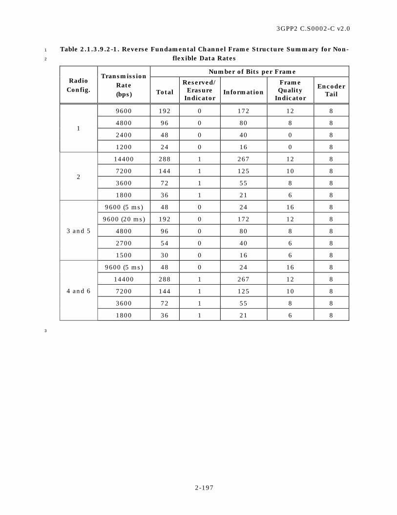
3GPP2 C.S0002-C v2.0
2-197
Table 2.1.3.9.2-1. Reverse Fundamental Channel Frame Structure Summary for Non-1
flexible Data Rates 2
Number of Bits per Frame Radio
Config.
Transmission Rate (bps) Total
Reserved/Erasure
Indicator Information
Frame Quality
Indicator
Encoder Tail
9600 192 0 172 12 8
4800 96 0 80 8 8
2400 48 0 40 0 8 1
1200 24 0 16 0 8
14400 288 1 267 12 8
7200 144 1 125 10 8
3600 72 1 55 8 8 2
1800 36 1 21 6 8
9600 (5 ms) 48 0 24 16 8
9600 (20 ms) 192 0 172 12 8
4800 96 0 80 8 8
2700 54 0 40 6 8
3 and 5
1500 30 0 16 6 8
9600 (5 ms) 48 0 24 16 8
14400 288 1 267 12 8
7200 144 1 125 10 8
3600 72 1 55 8 8
4 and 6
1800 36 1 21 6 8
3

3GPP2 C.S0002-C v2.0
2-198
Table 2.1.3.9.2-2. Reverse Fundamental Channel Frame Structure Summary for 1
Flexible Data Rates 2
Number of Bits per Frame
Radio Config.
Data Rate (bps) Total Information
Frame Quality
Indicator
Encoder Tail
4850 to 9600 97 to 192 73 to 168 16 8
4850 to 9550 97 to 191 77 to 171 12 8
2750 to 4800 55 to 96 31 to 72 16 8
2750 to 4800 55 to 96 35 to 76 12 8
2750 to 4750 55 to 95 39 to 79 8 8
1550 to 2700 31 to 54 7 to 30 16 8
1550 to 2700 31 to 54 11 to 34 12 8
1550 to 2700 31 to 54 15 to 38 8 8
1550 to 2650 31 to 53 17 to 39 6 8
1250 to 1500 25 to 30 1 to 6 16 8
1050 to 1500 21 to 30 1 to 10 12 8
850 to 1500 17 to 30 1 to 14 8 8
3 and 5
750 to 1450 15 to 29 1 to 15 6 8
7250 to 14400 145 to 288 121 to 264 16 8
7250 to 14300, 14400
145 to 286, 288
125 to 266, 268
12 8
3650 to 7200 73 to 144 49 to 120 16 8
3650 to 7200 73 to 144 53 to 124 12 8
3650 to 7100, 7200 73 to 142, 144 55 to 124, 126 10 8
1850 to 3600 37 to 72 13 to 48 16 8
1850 to 3600 37 to 72 17 to 52 12 8
1850 to 3600 37 to 72 19 to 54 10 8
1850 to 3500, 3600 37 to 70, 72 21 to 54, 56 8 8
1250 to 1800 25 to 36 1 to 12 16 8
1050 to 1800 21 to 36 1 to 16 12 8
950 to 1800 19 to 36 1 to 18 10 8
850 to 1800 17 to 36 1 to 20 8 8
4 and 6
750 to 1700, 1800 15 to 34, 36 1 to 20, 22 6 8
3

3GPP2 C.S0002-C v2.0
2-199
Information Bits F TR/E
Notation
R/E - Reserved/Erasure Indicator BitF - Frame Quality Indicator (CRC)T - Encoder Tail Bits
1
Figure 2.1.3.9.2-1. Reverse Fundamental Channel Frame Structure 2
3
2.1.3.9.2.1 Reverse Fundamental Channel Frame Quality Indicator 4
Each frame with Radio Configurations 2 through 6, and the 9600 and 4800 bps frames of 5
Radio Configuration 1 shall include a frame quality indicator. This frame quality indicator 6
is a CRC.20 No frame quality indicator is used for the 2400 and 1200 bps data rates of 7
Radio Configuration 1. 8
The frame quality indicator (CRC) shall be calculated on all bits within the frame, except 9
the frame quality indicator itself and the Encoder Tail Bits. 10
The 5 ms frames shall use a 16-bit frame quality indicator. 11
The 9600 bps transmissions with Radio Configuration 1 and the 14400 bps transmissions 12
with Radio Configuration 2 shall use a 12-bit frame quality indicator. 13
The 7200 bps transmissions with Radio Configuration 2 shall use a 10-bit frame quality 14
indicator. 15
The 4800 bps transmissions with Radio Configuration 1 and the 3600 bps transmissions 16
with Radio Configuration 2 shall use an 8-bit frame quality indicator. 17
The 1800 bps transmissions with Radio Configuration 2 shall use a 6-bit frame quality 18
indicator. 19
The 20 ms frames in Radio Configurations 3 and 5 with more than 96 total bits and in 20
Radio Configurations 4 and 6 with more than 144 total bits shall use a 12-bit frame 21
quality indicator. A 16-bit frame quality indicator may be used if flexible data rates are 22
supported. 23
The 20 ms frames in Radio Configurations 4 and 6 with 73 to 144 total bits shall use a 10-24
bit frame quality indicator. A 16-bit or 12-bit frame quality indicator may be used if 25
flexible data rates are supported. 26
20The frame quality indicator supports two functions at the receiver: The first function is to
determine whether the frame is in error. The second function is to assist in the determination of the
data rate of the received frame. Other parameters may be needed for rate determination in addition
to the frame quality indicator, such as symbol error rate evaluated at the four data rates of the
Reverse Fundamental Channel.

3GPP2 C.S0002-C v2.0
2-200
The 20 ms frames in Radio Configurations 3 and 5 with 55 to 96 total bits shall use an 8-1
bit frame quality indicator. A 16-bit or 12-bit frame quality indicator may be used if 2
flexible data rates are supported. 3
The 20 ms frames in Radio Configurations 4 and 6 with 37 to 72 total bits shall use an 8-4
bit frame quality indicator. A 16-bit, 12-bit, or 10-bit frame quality indicator may be used 5
if flexible data rates are supported. 6
The 20 ms frames in Radio Configurations 3 and 5 with 54 or fewer total bits shall use a 6-7
bit frame quality indicator. A 16-bit, 12-bit, or 8-bit frame quality indicator may be used if 8
flexible data rates are supported. 9
The 20 ms frames in Radio Configurations 4 and 6 with 36 or fewer total bits shall use a 6-10
bit frame quality indicator. A 16-bit, 12-bit, 10-bit, or 8-bit frame quality indicator may be 11
used if flexible data rates are supported. 12
The generator polynomials for the frame quality indicator shall be as follows: 13
g(x) = x16 + x15 + x14 + x11 + x6 + x5 + x2 + x + 1 for the 16-bit frame quality indicator, 14
g(x) = x12 + x11 + x10 + x9 + x8 + x4 + x + 1 for the 12-bit frame quality indicator, 15
g(x) = x10 + x9 + x8 + x7 + x6 + x4 + x3 + 1 for the 10-bit frame quality indicator, 16
g(x) = x8 + x7 + x4 + x3 + x + 1 for the 8-bit frame quality indicator, 17
g(x) = x6 + x2 + x + 1 for the 6-bit frame quality indicator (RC = 2), and 18
g(x) = x6 + x5 + x2 + x + 1 for the 6-bit frame quality indicator (3 ≤ RC ≤ 6). 19
The frame quality indicators shall be computed according to the following procedure as 20
shown in Figure 2.1.3.9.2-1 through Figure 2.1.3.9.2.1-6: 21
• Initially, all shift register elements shall be set to logical one and the switches shall 22
be set in the up position. 23
• The register shall be clocked a number of times equal to the number of 24
Reserved/Erasure Indicator Bits and information bits in the frame with those bits 25
as input. 26
• The switches shall be set in the down position so that the output is a modulo-2 27
addition with a ‘0’ and the successive shift register inputs are ‘0’s. 28
• The register shall be clocked an additional number of times equal to the number of 29
bits in the frame quality indicator (16, 12, 10, 8, or 6). 30
• These additional bits shall be the frame quality indicator bits. 31
• The bits shall be transmitted in the order calculated. 32
33

3GPP2 C.S0002-C v2.0
2-201
0
Input
0
Output
Denotes one-bit storage element
Denotes modulo-2 addition
Up for the information bits
Down for the last 16 bits
x0 x6 x14x11 x15x1 x2 x5
1
Figure 2.1.3.9.2.1-1. Reverse Fundamental Channel Frame Quality Indicator 2
Calculation for the 16-Bit Frame Quality Indicator 3
4
0
Input
0
Output
Denotes one-bit storage element
Denotes modulo-2 additionUp for the information bits and the reserved bitDown for the last 12 bits
x0 x1 x4 x9x8 x10 x11
5
Figure 2.1.3.9.2.1-2. Reverse Fundamental Channel Frame Quality Indicator 6
Calculation for the 12-Bit Frame Quality Indicator 7
8
0
Input
0
Output
Denotes one-bit storage element
Denotes modulo-2 addition
Up for the information bits and thereserved bitDown for the last 10 bits
x0 x1 x3 x7x5 x8 x9x2 x4 x6
9
Figure 2.1.3.9.2.1-3. Reverse Fundamental Channel Frame Quality Indicator 10
Calculation for the 10-Bit Frame Quality Indicator 11
12
0
Input
0
Output
Denotes one-bit storage element
Denotes modulo-2 addition
Up for the information bits and the reservedbitDown for the last 8 bits
x0 x1 x2 x3 x4 x5 x6 x7
13
Figure 2.1.3.9.2.1-4. Reverse Fundamental Channel Frame Quality Indicator 14
Calculation for the 8-Bit Frame Quality Indicator 15

3GPP2 C.S0002-C v2.0
2-202
1
0
Input
0
Output
Denotes one-bit storage element
Denotes modulo-2 addition
Up for the information bitsand the reserved bitDown for the last 6 bits
x0 x1 x2 x3 x4 x5
2
Figure 2.1.3.9.2.1-5. Reverse Fundamental Channel Frame Quality Indicator 3
Calculation for the 6-Bit Frame Quality Indicator for Radio Configuration 2 4
5
0
Input
0
Output
Denotes one-bit storage element
Denotes modulo-2 additionUp for the information bits and the reserved bitDown for the last 6 bits
x0 x1 x2 x3 x4 x5
6
Figure 2.1.3.9.2.1-6. Reverse Fundamental Channel Frame Quality Indicator 7
Calculation for the 6-Bit Frame Quality Indicator 8
for Radio Configurations 3 through 6 9
10
2.1.3.9.2.2 Reverse Fundamental Channel Encoder Tail Bits 11
The last eight bits of each Reverse Fundamental Channel frame are called the Encoder Tail 12
Bits. These eight bits shall each be set to ‘0’. 13
2.1.3.9.2.3 Reverse Traffic Channel Preambles 14
The Reverse Traffic Channel preamble is transmitted on the Reverse Pilot Channel or 15
Reverse Fundamental Channel to aid the base station in acquiring the Reverse 16
Fundamental Channel transmissions. 17

3GPP2 C.S0002-C v2.0
2-203
2.1.3.9.2.3.1 Radio Configurations 1 and 2 1
The Reverse Traffic Channel preamble shall consist of a frame of all zeros that is 2
transmitted with a 100% transmission duty cycle. The Reverse Traffic Channel preamble 3
shall not include the frame quality indicator. For Radio Configuration 1, the Reverse 4
Traffic Channel preamble shall consist of 192 zeros that are transmitted at the 9600 bps 5
rate. For Radio Configuration 2, the Reverse Traffic Channel preamble shall consist of 288 6
zeros that are transmitted at the 14400 bps rate. 7
When performing a hard handoff, the mobile station shall transmit the Reverse Traffic 8
Channel preamble for NUM_PREAMBLEs frames. 9
2.1.3.9.2.3.2 Radio Configurations 3 through 6 10
The Reverse Traffic Channel preamble is transmitted on the Reverse Pilot Channel as 11
specified in 2.1.3.2.4. 12
2.1.3.9.3 Reverse Fundamental Channel Convolutional Encoding 13
The Reverse Fundamental Channel shall be convolutionally encoded as specified in 14
2.1.3.1.4. 15
When generating Reverse Fundamental Channel data, the encoder shall be initialized to 16
the all zero state at the end of each 5 or 20 ms frame. 17
2.1.3.9.4 Reverse Fundamental Channel Code Symbol Repetition 18
Reverse Fundamental Channel code symbol repetition shall be as specified in2.1.3.1.5. 19
2.1.3.9.5 Reverse Fundamental Channel Code Symbol Puncturing 20
Reverse Fundamental Channel code symbol puncturing shall be as specified in 2.1.3.1.6. 21
2.1.3.9.6 Reverse Fundamental Channel Interleaving 22
The Reverse Fundamental Channel shall be interleaved as specified in 2.1.3.1.7. 23
2.1.3.9.7 Reverse Fundamental Channel Modulation and Orthogonal Spreading 24
The Reverse Fundamental Channel data shall be modulated as specified in 2.1.3.1.8. 25
When using Radio Configurations 1 and 2, the Reverse Fundamental Channel data shall 26
be modulated as specified in 2.1.3.1.8.1. When using Radio Configurations 3 through 6, 27
the Reverse Fundamental Channel data shall be modulated and orthogonally spread as 28
specified in 2.1.3.1.8.2. 29
2.1.3.9.8 Reverse Fundamental Channel Gating 30
The mobile station shall perform the data burst randomizing function as specified in 31
2.1.3.1.9 while transmitting on the Reverse Fundamental Channel with Radio 32
Configuration 1 or 2. 33
The transmission of the Reverse Fundamental Channel with Radio Configuration 3, 4, 5, 34
or 6 may be gated when no other Reverse Traffic Channel is assigned, FPC_MODEs is not 35
‘010’, and the data rate is 1500 bps for Radio Configuration 3 and 5, or 1800 bps for Radio 36

3GPP2 C.S0002-C v2.0
2-204
Configuration 4 and 6. The mobile station shall operate in the Reverse Fundamental 1
Channel gating mode if and only if REV_FCH_GATING_MODEs is equal to ‘1’. 2
When the Reverse Fundamental Channel with Radio Configuration 3, 4, 5, or 6 is operated 3
in the gated mode at a data rate of 1500 bps for Radio Configurations 3 and 5, or 1800 bps 4
for Radio Configurations 4 and 6 (i.e., when REV_FCH_GATING_MODEs = 1), the Reverse 5
Fundamental Channel shall have a transmission duty cycle of 50%. The Reverse 6
Fundamental Channel shall be transmitted in power control groups 2, 3, 6, 7, 10, 11, 14, 7
and 15, and shall not be transmitted in power control groups 0, 1, 4, 5, 8, 9, 12, and 13, 8
as shown in Figure 2.1.3.9.8-1. 9
10
0 1 2 3 4 5 6 7 8 9 10 11 12 13 14 15
20 ms = 16 Power Control Groups
1.25 ms = 1 Power Control Group
Reverse Pilot ChannelPilot Power Control Bit
Reverse Fundamental Channel 11
Figure 2.1.3.9.8-1. Gating Operation When the Reverse Fundamental Channel Data 12
Rate is 1500 bps for Radio Configuration 3 and 5 or 1800 bps for Radio Configuration 13
4 and 6 14
15
2.1.3.9.9 Reverse Fundamental Channel Direct Sequence Spreading 16
When operating in Radio Configuration 1 or 2, the Reverse Fundamental Channel shall be 17
spread by the long code as specified in 2.1.3.1.11. 18
2.1.3.9.10 Reverse Fundamental Channel Quadrature Spreading 19
The Reverse Fundamental Channel shall be quadrature spread as specified in 2.1.3.1.12. 20
2.1.3.9.11 Reverse Fundamental Channel Baseband Filtering 21
The Reverse Fundamental Channel shall be filtered as specified in 2.1.3.1.13. 22

3GPP2 C.S0002-C v2.0
2-205
2.1.3.9.12 Reverse Fundamental Channel Transmission Processing 1
When the Physical Layer receives a PHY-FCH.Request(SDU, FRAME_DURATION, 2
NUM_BITS) from the MAC Layer, the mobile station shall perform the following: 3
• Store the arguments SDU, FRAME_DURATION, and NUM_BITS. 4
• If SDU is not equal to NULL, set the information bits to SDU. 5
• If SDU is not equal to NULL, transmit NUM_BITS bits of SDU on a Reverse 6
Fundamental Channel frame of duration FRAME_DURATION (5 ms or 20 ms). If a 7
PHY-FCH.Request primitive for a 5 ms frame is received coincident with a PHY-8
FCH.Request primitive for a 20 ms frame or during transmission of a 20 ms frame, 9
then the mobile station may preempt transmission of the 20 ms frame and 10
transmit a 5 ms frame. Transmission of the 20 ms frame may start or resume after 11
completion of the 5 ms frame. If transmission of the 20 ms frame is resumed after 12
an interruption in transmission, then the relative power level of the Reverse 13
Fundamental Channel modulation symbols shall be equal to that of the 14
modulation symbols sent prior to the preemption. 15
2.1.3.10 Reverse Supplemental Channel 16
The Reverse Supplemental Channel applies to Radio Configurations 3 through 6 only. 17
The Reverse Supplemental Channel is used for the transmission of user 18
informationhigher-level data to the base station during a call. The Reverse Traffic Channel 19
contains up to two Reverse Supplemental Channels. 20
2.1.3.10.1 Reverse Supplemental Channel Time Alignment and Modulation Rates 21
When transmitting on the Reverse Supplemental Channel with a single assigned data rate 22
in Radio Configuration 3, the mobile station shall transmit information at fixed data rates 23
of 307200, 153600, 76800, 38400, 19200, 9600, 4800, 2700, 2400, 1500, 1350, or 1200 24
bps. 25
The mobile station may support flexible data rates. If flexible data rates are supported, 26
• When transmitting on the Reverse Supplemental Channel with a single assigned 27
data rate and 20 ms frames in Radio Configuration 3, the mobile station should 28
transmit information at a fixed data rate corresponding to 15 to 6143 total bits per 29
frame in 1 bit increments. The mobile station need not support flexible rates with 30
less than 16 information bits per frame. 31
• When transmitting on the Reverse Supplemental Channel with a single assigned 32
data rate and 40 ms frames in Radio Configuration 3, the mobile station should 33
transmit information at a fixed data rate corresponding to 31 to 6143 total bits per 34
frame in 1 bit increments. The mobile station need not support flexible rates with 35
less than 40 information bits per frame. 36

3GPP2 C.S0002-C v2.0
2-206
• When transmitting on the Reverse Supplemental Channel with a single assigned 1
data rate and 80 ms frames in Radio Configuration 3, the mobile station should 2
transmit information at a fixed data rate corresponding to 55 to 6143 total bits per 3
frame in 1 bit increments. The mobile station need not support flexible rates with 4
less than 80 information bits per frame. 5
When transmitting on the Reverse Supplemental Channel with a single assigned data rate 6
in Radio Configuration 4, the mobile station shall transmit information at fixed data rates 7
of 230400, 115200, 57600, 28800, 14400, 7200, 3600, or 1800 bps. 8
If flexible data rates are supported, 9
• When transmitting on the Reverse Supplemental Channel with a single assigned 10
data rate and 20 ms frames in Radio Configuration 4, the mobile station should 11
transmit information at a fixed data rate corresponding to 15 to 4607 total bits per 12
frame in 1 bit increments. The mobile station need not support flexible rates with 13
less than 22 information bits per frame. 14
• When transmitting on the Reverse Supplemental Channel with a single assigned 15
data rate and 40 ms frames in Radio Configuration 4, the mobile station should 16
transmit information at a fixed data rate corresponding to 37 to 4607 total bits per 17
frame in 1 bit increments. The mobile station need not support flexible rates with 18
less than 56 information bits per frame. 19
• When transmitting on the Reverse Supplemental Channel with a single assigned 20
data rate and 80 ms frames in Radio Configuration 4, the mobile station should 21
transmit information at a fixed data rate corresponding to 73 to 4607 total bits per 22
frame in 1 bit increments. The mobile station need not support flexible rates with 23
less than 126 information bits per frame. 24
When transmitting on the Reverse Supplemental Channel with a single assigned data rate 25
in Radio Configuration 5, the mobile station shall transmit information at a fixed data rate 26
of 614400, 307200, 153600, 76800, 38400, 19200, 9600, 4800, 2700, 2400, 1500, 1350, 27
or 1200 bps. 28
If flexible data rates are supported, 29
• When transmitting on the Reverse Supplemental Channel with a single assigned 30
data rate and 20 ms frames in Radio Configuration 5, the mobile station should 31
transmit information at a fixed data rate corresponding to 15 to 12287 total bits 32
per frame in 1 bit increments. The mobile station need not support flexible rates 33
with less than 16 information bits per frame. 34
• When transmitting on the Reverse Supplemental Channel with a single assigned 35
data rate and 40 ms frames in Radio Configuration 5, the mobile station should 36
transmit information at a fixed data rate corresponding to 31 to 12287 total bits 37
per frame in 1 bit increments. The mobile station need not support flexible rates 38
with less than 40 information bits per frame. 39

3GPP2 C.S0002-C v2.0
2-207
• When transmitting on the Reverse Supplemental Channel with a single assigned 1
data rate and 80 ms frames in Radio Configuration 5, the mobile station should 2
transmit information at a fixed data rate corresponding to 55 to 12287 total bits 3
per frame in 1 bit increments. The mobile station need not support flexible rates 4
with less than 80 information bits per frame. 5
When transmitting on the Reverse Supplemental Channel with a single assigned data rate 6
in Radio Configuration 6, the mobile station shall transmit information at a fixed data rate 7
of 1036800, 518400, 460800, 259200, 230400, 115200, 57600, 28800, 14400, 7200, 8
3600, or 1800 bps. 9
If flexible data rates are supported, 10
• When transmitting on the Reverse Supplemental Channel with a single assigned 11
data rate and 20 ms frames in Radio Configuration 6, the mobile station should 12
transmit information at a fixed data rate corresponding to 15 to 20735 total bits 13
per frame in 1 bit increments. The mobile station need not support flexible rates 14
with less than 22 information bits per frame. 15
• When transmitting on the Reverse Supplemental Channel with a single assigned 16
data rate and 40 ms frames in Radio Configuration 6, the mobile station should 17
transmit information at a fixed data rate corresponding to 37 to 20735 total bits 18
per frame in 1 bit increments. The mobile station need not support flexible rates 19
with less than 56 information bits per frame. 20
• When transmitting on the Reverse Supplemental Channel with a single assigned 21
data rate and 80 ms frames in Radio Configuration 6, the mobile station should 22
transmit information at a fixed data rate corresponding to 73 to 20735 total bits 23
per frame in 1 bit increments. The mobile station need not support flexible rates 24
with less than 126 information bits per frame. 25
When using variable-rate transmission on the Reverse Supplemental Channel with 26
multiple assigned data rates in Radio Configurations 3, 4, 5, and 6, the mobile station 27
shall 28
• Transmit information at the maximal assigned data rate, or 29
• Transmit information at the other assigned data rates with the same modulation 30
symbol rate as that of the maximal assigned data rate. To achieve a higher 31
modulation symbol rate, repetition or puncturing is applied to the specified data 32
rate. 33
If the mobile station supports the Reverse Supplemental Channel, the mobile station shall 34
support Reverse Supplemental Channel frames that are 20 ms in duration. The mobile 35
station may support Reverse Supplemental Channel frames that are 40 or 80 ms in 36
duration. The mobile station may support discontinuous transmission of Reverse 37
Supplemental Channel frames. 38
The mobile station shall support Reverse Supplemental Channel frames that are time 39
offset by multiples of 1.25 ms as specified by FRAME_OFFSETs. The mobile station may 40
support 40 or 80 ms Reverse Supplemental Channel frames that are time offset by 41

3GPP2 C.S0002-C v2.0
2-208
multiples of 20 ms as specified by REV_SCH_FRAME_OFFSETs[i]s, where i = 1 and 2 for 1
Reverse Supplemental Channel 1 and Reverse Supplemental Channel 2, respectively. 2
The amount of the time offset is specified by FRAME_OFFSETs and 3
REV_SCH_FRAME_OFFSETs[i]s, where i = 1 or 2. A zero-offset 20 ms Reverse 4
Supplemental Channel frame shall begin only when System Time is an integral multiple of 5
20 ms (see Figure 1.3-1). A zero-offset 40 ms Reverse Supplemental Channel frame shall 6
begin only when System Time is an integral multiple of 40 ms. A zero-offset 80 ms Reverse 7
Supplemental Channel frame shall begin only when System Time is an integral multiple of 8
80 ms. An offset 20 ms Reverse Supplemental Channel frame shall begin 1.25 9
× FRAME_OFFSETs ms later than the zero-offset 20 ms Reverse Supplemental Channel 10
frame. An offset 40 ms Reverse Supplemental Channel frame shall begin (1.25 11
× FRAME_OFFSETs + 20 × REV_SCH_FRAME_OFFSETs[i]s) ms later than the zero-offset 40 12
ms Reverse Supplemental Channel frame. An offset 80 ms Reverse Supplemental Channel 13
frame shall begin (1.25 × FRAME_OFFSETs + 20 × REV_SCH_FRAME_OFFSETs[i]s) ms later 14
than the zero-offset 80 ms Reverse Supplemental Channel frame. The interleaver block for 15
the Reverse Supplemental Channels shall be aligned with the Reverse Supplemental 16
Channel frame. 17
2.1.3.10.2 Reverse Supplemental Channel Frame Structure 18
Table 2.1.3.10.2-1 through Table 2.1.3.10.2-3 summarize the Reverse Supplemental 19
Channel bit allocations for non-flexible data rates. Table 2.1.3.10.2-4 through Table 20
2.1.3.10.2-8 summarize the Reverse Supplemental Channel bit allocations for flexible data 21
rates. All frames shall consist of zero or one Reserved Bits followed by the information bits, 22
a frame quality indicator (CRC), and eight Encoder Tail Bits, as shown in Figure 23
2.1.3.10.2-1. 24
All frames with Radio Configurations 3 and 5 and the frames with Radio Configurations 4 25
and 6 with data rates above 14400 bps shall consist of the information bits, followed by 26
the frame quality indicator (CRC) and eight Encoder Tail Bits. All frames with Radio 27
Configurations 4 and 6 with data rates equal to or less than 14400 bps shall consist of 28
zero or one Reserved Bits, followed by the information bits, frame quality indicator (CRC), 29
and eight Encoder Tail Bits. 30
31
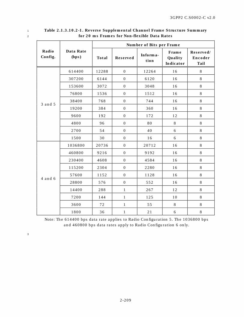
3GPP2 C.S0002-C v2.0
2-209
Table 2.1.3.10.2-1. Reverse Supplemental Channel Frame Structure Summary 1
for 20 ms Frames for Non-flexible Data Rates 2
Number of Bits per Frame
Radio Config.
Data Rate (bps) Total Reserved
Informa-tion
Frame Quality
Indicator
Reserved/ Encoder
Tail
614400 12288 0 12264 16 8
307200 6144 0 6120 16 8
153600 3072 0 3048 16 8
76800 1536 0 1512 16 8
38400 768 0 744 16 8
19200 384 0 360 16 8
9600 192 0 172 12 8
4800 96 0 80 8 8
2700 54 0 40 6 8
3 and 5
1500 30 0 16 6 8
1036800 20736 0 20712 16 8
460800 9216 0 9192 16 8
230400 4608 0 4584 16 8
115200 2304 0 2280 16 8
57600 1152 0 1128 16 8
28800 576 0 552 16 8
14400 288 1 267 12 8
7200 144 1 125 10 8
3600 72 1 55 8 8
4 and 6
1800 36 1 21 6 8
Note: The 614400 bps data rate applies to Radio Configuration 5. The 1036800 bps and 460800 bps data rates apply to Radio Configuration 6 only.
3

3GPP2 C.S0002-C v2.0
2-210
Table 2.1.3.10.2-2. Reverse Supplemental Channel Frame Structure Summary 1
for 40 ms Frames for Non-flexible Data Rates 2
Number of Bits per Frame
Radio Config.
Data Rate (bps) Total Reserved
Informa-tion
Frame Quality
Indicator
Reserved/ Encoder
Tail
307200 12288 0 12264 16 8
153600 6144 0 6120 16 8
76800 3072 0 3048 16 8
38400 1536 0 1512 16 8
19200 768 0 744 16 8
9600 384 0 360 16 8
4800 192 0 172 12 8
2400 96 0 80 8 8
3 and 5
1350 54 0 40 6 8
518400 20736 0 20712 16 8
230400 9216 0 9192 16 8
115200 4608 0 4584 16 8
57600 2304 0 2280 16 8
28800 1152 0 1128 16 8
14400 576 0 552 16 8
7200 288 1 267 12 8
3600 144 1 125 10 8
4 and 6
1800 72 1 55 8 8
Note: The 307200 bps data rate applies to Radio Configuration 5. The 518400 bps and 230400 bps data rates apply to Radio Configuration 6 only.
3

3GPP2 C.S0002-C v2.0
2-211
Table 2.1.3.10.2-3. Reverse Supplemental Channel Frame Structure Summary 1
for 80 ms Frames for Non-flexible Data Rates 2
Number of Bits per Frame
Radio Config.
Data Rate (bps) Total Reserved
Informa-tion
Frame Quality
Indicator
Reserved/ Encoder
Tail
153600 12288 0 12264 16 8
76800 6144 0 6120 16 8
38400 3072 0 3048 16 8
19200 1536 0 1512 16 8
9600 768 0 744 16 8
4800 384 0 360 16 8
2400 192 0 172 12 8
3 and 5
1200 96 0 80 8 8
259200 20736 0 20712 16 8
115200 9216 0 9192 16 8
57600 4608 0 4584 16 8
28800 2304 0 2280 16 8
14400 1152 0 1128 16 8
7200 576 0 552 16 8
3600 288 1 267 12 8
4 and 6
1800 144 1 125 10 8
Note: The 153600 bps data rate applies to Radio Configuration 5. The 259200 bps and 115200 bps data rates apply to Radio Configuration 6 only.
3

3GPP2 C.S0002-C v2.0
2-212
Table 2.1.3.10.2-4. Reverse Supplemental Channel Frame Structure Summary 1
for 20 ms Frames for Flexible Data Rates (Part 1 of 2) 2
Number of Bits per Frame
Radio Config.
Data Rate (bps) Total Information
Frame Quality
Indicator
Reserved/ Encoder
Tail
5 307250 to 614350 6145 to 12287 6121 to 12263 16 8
153650 to 307150 3073 to 6143 3049 to 6119 16 8
76850 to 153550 1537 to 3071 1513 to 3047 16 8
38450 to 76750 769 to 1535 745 to 1511 16 8
19250 to 38350 385 to 767 361 to 743 16 8
9650 to 19150 193 to 383 169 to 359 16 8
4850 to 9600 97 to 192 73 to 168 16 8
4850 to 9550 97 to 191 77 to 171 12 8
2750 to 4800 55 to 96 31 to 72 16 8
2750 to 4800 55 to 96 35 to 76 12 8
2750 to 4750 55 to 95 39 to 79 8 8
1550 to 2700 31 to 54 7 to 30 16 8
1550 to 2700 31 to 54 11 to 34 12 8
1550 to 2700 31 to 54 15 to 38 8 8
1550 to 2650 31 to 53 17 to 39 6 8
1250 to 1500 25 to 30 1 to 6 16 8
1050 to 1500 21 to 30 1 to 10 12 8
850 to 1500 17 to 30 1 to 14 8 8
3 and 5
750 to 1450 15 to 29 1 to 15 6 8
3

3GPP2 C.S0002-C v2.0
2-213
Table 2.1.3.10.2-5. Reverse Supplemental Channel Frame Structure Summary 1
for 20 ms Frames for Flexible Data Rates (Part 2 of 2) 2
Number of Bits per Frame
Radio Config.
Data Rate (bps) Total Information
Frame Quality
Indicator
Reserved/ Encoder
Tail
460850 to 1036750
9217 to 20735 9193 to 20711 16 8 6
230450 to 460750 4609 to 9215 4585 to 9191 16 8
115250 to 230350 2305 to 4607 2281 to 4583 16 8
57650 to 115150 1153 to 2303 1129 to 2279 16 8
28850 to 57550 577 to 1151 553 to 1127 16 8
14450 to 28750 289 to 575 265 to 551 16 8
7250 to 14400 145 to 288 121 to 264 16 8
7250 to 14300, 14400
145 to 286, 288 125 to 266,
268 12 8
3650 to 7200 73 to 144 49 to 120 16 8
3650 to 7200 73 to 144 53 to 124 12 8
3650 to 7100, 7200
73 to 142, 144 55 to 124, 126 10 8
1850 to 3600 37 to 72 13 to 48 16 8
1850 to 3600 37 to 72 17 to 52 12 8
1850 to 3600 37 to 72 19 to 54 10 8
1850 to 3500, 3600
37 to 70, 72 21 to 54, 56 8 8
1250 to 1800 25 to 36 1 to 12 16 8
1050 to 1800 21 to 36 1 to 16 12 8
950 to 1800 19 to 36 1 to 18 10 8
850 to 1800 17 to 36 1 to 20 8 8
4 and 6
750 to 1700, 1800 15 to 34, 36 1 to 20, 22 6 8
3

3GPP2 C.S0002-C v2.0
2-214
Table 2.1.3.10.2-6. Reverse Supplemental Channel Frame Structure Summary 1
for 40 ms Frames for Flexible Data Rates (Part 1 of 2) 2
Number of Bits per Frame Radio
Config. Data Rate
(bps) Total Information Frame Quality
Indicator
Reserved/ Encoder
Tail
5 153625 to 307175 6145 to 12287 6121 to 12263 16 8
76825 to 153575 3073 to 6143 3049 to 6119 16 8
38425 to 76775 1537 to 3071 1513 to 3047 16 8
19225 to 38375 769 to 1535 745 to 1511 16 8
9625 to 19175 385 to 767 361 to 743 16 8
4825 to 9575 193 to 383 169 to 359 16 8
2425 to 4800 97 to 192 73 to 168 16 8
2425 to 4775 97 to 191 77 to 171 12 8
1375 to 2400 55 to 96 31 to 72 16 8
1375 to 2400 55 to 96 35 to 76 12 8
1375 to 2375 55 to 95 39 to 79 8 8
775 to 1350 31 to 54 7 to 30 16 8
775 to 1350 31 to 54 11 to 34 12 8
775 to 1350 31 to 54 15 to 38 8 8
3 and 5
775 to 1325 31 to 53 17 to 39 6 8
3

3GPP2 C.S0002-C v2.0
2-215
Table 2.1.3.10.2-7. Reverse Supplemental Channel Frame Structure Summary 1
for 40 ms Frames for Flexible Data Rates (Part 2 of 2) 2
Number of Bits per Frame Radio
Config. Data Rate
(bps) Total Information Frame Quality
Indicator
Reserved/ Encoder
Tail
230425 to 518375 9217 to 20735 9193 to 20711 16 8 6
115225 to 230375 4609 to 9215 4585 to 9191 16 8
57625 to 115175 2305 to 4607 2281 to 4583 16 8
28825 to 57575 1153 to 2303 1129 to 2279 16 8
14425 to 28775 577 to 1151 553 to 1127 16 8
7225 to 14375 289 to 575 265 to 551 16 8
3625 to 7200 145 to 288 121 to 264 16 8
3625 to 7150, 7200 145 to 286, 288
125 to 266, 268
12 8
1825 to 3600 73 to 144 49 to 120 16 8
1825 to 3600 73 to 144 53 to 124 12 8
1825 to 3550, 3600 73 to 142, 144 55 to 124, 126 10 8
925 to 1800 37 to 72 13 to 48 16 8
925 to 1800 37 to 72 17 to 52 12 8
925 to 1800 37 to 72 19 to 54 10 8
4 and 6
925 to 1750, 1800 37 to 70, 72 21 to 54, 56 8 8
3

3GPP2 C.S0002-C v2.0
2-216
Table 2.1.3.10.2-8. Reverse Supplemental Channel Frame Structure Summary 1
for 80 ms Frames for Flexible Data Rates 2
Number of Bits per Frame Radio
Config. Data Rate
(bps) Total Information Frame Quality
Indicator
Reserved/ Encoder
Tail
5 76812.5 to 153587.5 6145 to 12287 6121 to 12263 16 8
38412.5 to 76787.5 3073 to 6143 3049 to 6119 16 8
19212.5 to 38387.5 1537 to 3071 1513 to 3047 16 8
9612.5 to 19187.5 769 to 1535 745 to 1511 16 8
4812.5 to 9587.5 385 to 767 361 to 743 16 8
2412.5 to 4787.5 193 to 383 169 to 359 16 8
1212.5 to 2400 97 to 192 73 to 168 16 8
1212.5 to 2387.5 97 to 191 77 to 171 12 8
687.5 to 1200 55 to 96 31 to 72 16 8
687.5 to 1200 55 to 96 35 to 76 12 8
3 and 5
687.5 to 1187.5 55 to 95 39 to 79 8 8
115212.5 to 259187.5 9217 to 20735 9193 to 20711 16 8
6 57612.5 to 115187.5 4609 to 9215 4585 to 9191 16 8
28812.5 to 57587.5 2305 to 4607 2281 to 4583 16 8
14412.5 to 28787.5 1153 to 2303 1129 to 2279 16 8
7212.5 to 14387.5 577 to 1151 553 to 1127 16 8
3612.5 to 7187.5 289 to 575 265 to 551 16 8
1812.5 to 3600 145 to 288 121 to 264 16 8
1812.5 to 3575, 3600
145 to 286, 288
125 to 266, 268
12 8
912.5 to 1800 73 to 144 49 to 120 16 8
912.5 to 1800 73 to 144 53 to 124 12 8
4 and 6
912.5 to 1775, 1800 73 to 142, 144 55 to 124, 126 10 8
3

3GPP2 C.S0002-C v2.0
2-217
Information Bits F R/TR
R - Reserved BitF - Frame Quality Indicator (CRC)R/T - Reserved/Encoder Tail Bits
Notation
1
Figure 2.1.3.10.2-1. Reverse Supplemental Channel Frame Structure 2
3
2.1.3.10.2.1 Reverse Supplemental Channel Frame Quality Indicator 4
Each frame shall include a frame quality indicator. This frame quality indicator is a CRC. 5
The frame quality indicator (CRC) shall be calculated on all bits within the frame, except 6
the frame quality indicator itself and the Reserved/Encoder Tail Bits. 7
Frames in Radio Configurations 3 and 5 with more than 192 total bits and in Radio 8
Configurations 4 and 6 with more than 288 total bits shall use a 16-bit frame quality 9
indicator. 10
Frames in Radio Configurations 3 and 5 with 97 to 192 total bits and in Radio 11
Configurations 4 and 6 with 145 to 288 total bits shall use a 12-bit frame quality 12
indicator. A 16-bit frame quality indicator may be used if flexible data rates are supported. 13
Frames in Radio Configurations 4 and 6 with 73 to 144 total bits shall use a 10-bit frame 14
quality indicator. A 16-bit or 12-bit frame quality indicator may be used if flexible data 15
rates are supported. 16
Frames in Radio Configurations 3 and 5 with 55 to 96 total bits shall use an 8-bit frame 17
quality indicator. A 16-bit or 12-bit frame quality indicator may be used if flexible data 18
rates are supported. 19
Frames in Radio Configurations 4 and 6 with 37 to 72 total bits shall use an 8-bit frame 20
quality indicator. A 16-bit, 12-bit, or 10-bit frame quality indicator may be used if flexible 21
data rates are supported. 22
Frames in Radio Configurations 3 and 5 with 54 or fewer total bits shall use a 6-bit frame 23
quality indicator. A 16-bit, 12-bit, or 8-bit frame quality indicator may be used if flexible 24
data rates are supported. 25
Frames in Radio Configurations 4 and 6 with 36 or fewer total bits shall use a 6-bit frame 26
quality indicator. A 16-bit, 12-bit, 10-bit, or 8-bit frame quality indicator may be used if 27
flexible data rates are supported. 28
The generator polynomials for the frame quality indicator shall be as follows: 29
g(x) = x16 + x15 + x14 + x11 + x6 + x5 + x2 + x + 1 for the 16-bit frame quality indicator, 30
g(x) = x12 + x11 + x10 + x9 + x8 + x4 + x + 1 for the 12-bit frame quality indicator, 31
g(x) = x10 + x9 + x8 + x7 + x6 + x4 + x3 + 1 for the 10-bit frame quality indicator, 32

3GPP2 C.S0002-C v2.0
2-218
g(x) = x8 + x7 + x4 + x3 + x + 1 for the 8-bit frame quality indicator, and 1
g(x) = x6 + x5 + x2 + x + 1 for the 6-bit frame quality indicator. 2
The frame quality indicators shall be computed according to the following procedure as 3
shown in Figure 2.1.3.10.2-1 through Figure 2.1.3.10.2.1-5: 4
• Initially, all shift register elements shall be set to logical one and the switches shall 5
be set in the up position. 6
• The register shall be clocked a number of times equal to the number of Reserved 7
Bits and information bits in the frame with those bits as input. 8
• The switches shall be set in the down position so that the output is a modulo-2 9
addition with a ‘0’ and the successive shift register inputs are ‘0’s. 10
• The register shall be clocked an additional number of times equal to the number of 11
bits in the frame quality indicator (16, 12, 10, 8, or 6). 12
• These additional bits shall be the frame quality indicator bits. 13
• The bits shall be transmitted in the order calculated. 14
15
0
Input
0
Output
Denotes one-bit storage element
Denotes modulo-2 addition
Up for the information bits andthe reserved bitDown for the last 16 bits
x0 x6 x1411 x15x1 x2 x5
16
Figure 2.1.3.10.2.1-1. Reverse Supplemental Channel Frame Quality Indicator 17
Calculation for the 16-Bit Frame Quality Indicator 18
19
0
Input
0
Output
Denotes one-bit storage element
Denotes modulo-2 addition
Up the information bits andthe reserved bitDown for the last 12 bits
x0 x1 x4 x9x8 x10 x11
20
Figure 2.1.3.10.2.1-2. Reverse Supplemental Channel Frame Quality Indicator 21
Calculation for the 12-Bit Frame Quality Indicator 22
23
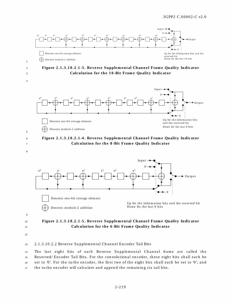
3GPP2 C.S0002-C v2.0
2-219
0
Input
0
Output
Denotes one-bit storage element
Denotes modulo-2 addition
Up for the information bits and thereserved bitDown for the last 10 bits
x0 x1 x3 x7x5 x8 x9x2 x4 x6
1
Figure 2.1.3.10.2.1-3. Reverse Supplemental Channel Frame Quality Indicator 2
Calculation for the 10-Bit Frame Quality Indicator 3
4
0
Input
0
Output
Denotes one-bit storage element
Denotes modulo-2 addition
Up for the information bitsand the reserved bit
Down for the last 8 bits
x0 x1 x2 x3 x4 x5 x6 x7
5
Figure 2.1.3.10.2.1-4. Reverse Supplemental Channel Frame Quality Indicator 6
Calculation for the 8-Bit Frame Quality Indicator 7
8
0
Input
0
Output
Denotes one-bit storage element
Denotes modulo-2 additionUp for the information bits and the reserved bitDown for the last 6 bits
x0 x1 x2 x3 x4 x5
9
Figure 2.1.3.10.2.1-5. Reverse Supplemental Channel Frame Quality Indicator 10
Calculation for the 6-Bit Frame Quality Indicator 11
12
2.1.3.10.2.2 Reverse Supplemental Channel Encoder Tail Bits 13
The last eight bits of each Reverse Supplemental Channel frame are called the 14
Reserved/Encoder Tail Bits. For the convolutional encoder, these eight bits shall each be 15
set to ‘0’. For the turbo encoder, the first two of the eight bits shall each be set to ‘0’, and 16
the turbo encoder will calculate and append the remaining six tail bits. 17

3GPP2 C.S0002-C v2.0
2-220
2.1.3.10.3 Reverse Supplemental Channel Forward Error Correction Encoding 1
The Reverse Supplemental Channel shall be convolutionally or turbo encoded as specified 2
in 2.1.3.1.4. 3
When generating Reverse Supplemental Channel data, the encoder shall be initialized to 4
the all zero state at the end of each frame. 5
2.1.3.10.4 Reverse Supplemental Channel Code Symbol Repetition 6
Reverse Supplemental Channel code symbol repetition shall be as specified in 2.1.3.1.5. 7
2.1.3.10.5 Reverse Supplemental Channel Code Symbol Puncturing 8
Reverse Supplemental Channel code symbol puncturing shall be as specified in 2.1.3.1.6. 9
2.1.3.10.6 Reverse Supplemental Channel Interleaving 10
The Reverse Supplemental Channel shall be interleaved as specified in 2.1.3.1.7. 11
2.1.3.10.7 Reverse Supplemental Channel Modulation and Orthogonal Spreading 12
The Reverse Supplemental Channel data shall be modulated and orthogonally spread as 13
specified in 2.1.3.1.8. 14
2.1.3.10.8 Reverse Supplemental Channel Quadrature Spreading 15
The Reverse Supplemental Channel shall be quadrature spread as specified in 2.1.3.1.12. 16
2.1.3.10.9 Reverse Supplemental Channel Baseband Filtering 17
The Reverse Supplemental Channel shall be filtered as specified in 2.1.3.1.13. 18
2.1.3.10.10 Reverse Supplemental Channel Transmission Processing 19
When the Physical Layer receives a PHY-SCH.Request(SDU, FRAME_DURATION, 20
NUM_BITS) from the MAC Layer, the mobile station shall perform the following: 21
• Store the arguments SDU, FRAME_DURATION, and NUM_BITS. 22
• If SDU is not equal to NULL, set the information bits to SDU. 23
• If SDU is not equal to NULL, transmit NUM_BITS bits of SDU in a Reverse 24
Supplemental Channel frame of duration FRAME_DURATION (20, 40, or 80 ms). 25
2.1.3.11 Reverse Supplemental Code Channel 26
The Reverse Supplemental Code Channel applies to Radio Configurations 1 and 2 only. 27
The Reverse Supplemental Code Channel is used for the transmission of user 28
informationhigher-level data to the base station during a call. The Reverse Traffic Channel 29
contains up to seven Reverse Supplemental Code Channels. 30
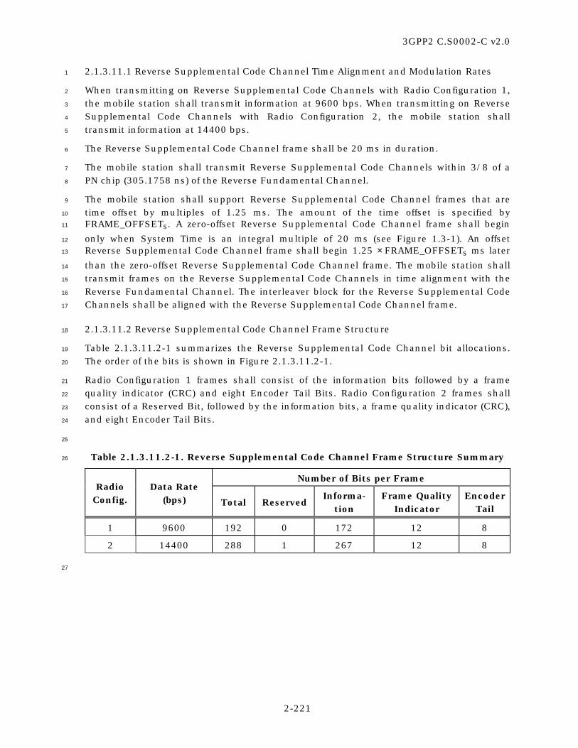
3GPP2 C.S0002-C v2.0
2-221
2.1.3.11.1 Reverse Supplemental Code Channel Time Alignment and Modulation Rates 1
When transmitting on Reverse Supplemental Code Channels with Radio Configuration 1, 2
the mobile station shall transmit information at 9600 bps. When transmitting on Reverse 3
Supplemental Code Channels with Radio Configuration 2, the mobile station shall 4
transmit information at 14400 bps. 5
The Reverse Supplemental Code Channel frame shall be 20 ms in duration. 6
The mobile station shall transmit Reverse Supplemental Code Channels within 3/8 of a 7
PN chip (305.1758 ns) of the Reverse Fundamental Channel. 8
The mobile station shall support Reverse Supplemental Code Channel frames that are 9
time offset by multiples of 1.25 ms. The amount of the time offset is specified by 10
FRAME_OFFSETs. A zero-offset Reverse Supplemental Code Channel frame shall begin 11
only when System Time is an integral multiple of 20 ms (see Figure 1.3-1). An offset 12
Reverse Supplemental Code Channel frame shall begin 1.25 × FRAME_OFFSETs ms later 13
than the zero-offset Reverse Supplemental Code Channel frame. The mobile station shall 14
transmit frames on the Reverse Supplemental Code Channels in time alignment with the 15
Reverse Fundamental Channel. The interleaver block for the Reverse Supplemental Code 16
Channels shall be aligned with the Reverse Supplemental Code Channel frame. 17
2.1.3.11.2 Reverse Supplemental Code Channel Frame Structure 18
Table 2.1.3.11.2-1 summarizes the Reverse Supplemental Code Channel bit allocations. 19
The order of the bits is shown in Figure 2.1.3.11.2-1. 20
Radio Configuration 1 frames shall consist of the information bits followed by a frame 21
quality indicator (CRC) and eight Encoder Tail Bits. Radio Configuration 2 frames shall 22
consist of a Reserved Bit, followed by the information bits, a frame quality indicator (CRC), 23
and eight Encoder Tail Bits. 24
25
Table 2.1.3.11.2-1. Reverse Supplemental Code Channel Frame Structure Summary 26
Number of Bits per Frame Radio
Config. Data Rate
(bps) Total Reserved Informa-
tion Frame Quality
Indicator Encoder
Tail
1 9600 192 0 172 12 8
2 14400 288 1 267 12 8
27

3GPP2 C.S0002-C v2.0
2-222
Information Bits F TR
Notation
R - Reserved BitF - Frame Quality Indicator (CRC)T - Encoder Tail Bits
1
Figure 2.1.3.11.2-1. Reverse Supplemental Code Channel Frame Structure 2
3
2.1.3.11.2.1 Reverse Supplemental Code Channel Frame Quality Indicator 4
The frame quality indicator (CRC) shall be calculated on all bits within the frame, except 5
the frame quality indicator itself and the Encoder Tail Bits. Each frame with Radio 6
Configuration 1 and 2 shall include a 12-bit frame quality indicator. This frame quality 7
indicator is a CRC. 8
The generator polynomial for the frame quality indicator shall be as follows: 9
g(x) = x12 + x11 + x10 + x9 + x8 + x4 + x + 1. 10
The frame quality indicator shall be computed according to the following procedure as 11
shown in Figure 2.1.3.11.2.1-1: 12
• Initially, all shift register elements shall be set to logical one and the switches shall 13
be set in the up position. 14
• The register shall be clocked a number of times equal to the number of Reserved 15
Bits and information bits in the frame with those bits as input. 16
• The switches shall be set in the down position so that the output is a modulo-2 17
addition with a ‘0’ and the successive shift register inputs are ‘0’s. 18
• The register shall be clocked an additional number of times equal to the number of 19
bits in the frame quality indicator (12). 20
• These additional bits shall be the frame quality indicator bits. 21
• The bits shall be transmitted in the order calculated. 22
23
0
Input
0
Output
Denotes one-bit storage element
Denotes modulo-2 addition
Up for the first 172 bits for the 9600 bps rateand for the first 268 bits for the 14400 rateDown for the last 12 bits
x0 x1 x4 x9x8 x10 x11
24
Figure 2.1.3.11.2.1-1. Reverse Supplemental Code Channel Frame Quality Indicator 25
Calculation 26

3GPP2 C.S0002-C v2.0
2-223
1
2.1.3.11.2.2 Reverse Supplemental Code Channel Encoder Tail Bits 2
The last eight bits of each Reverse Supplemental Code Channel frame are called the 3
Encoder Tail Bits. These eight bits shall each be set to ‘0’. 4
2.1.3.11.2.3 Reverse Supplemental Code Channel Preambles 5
The Reverse Supplemental Code Channel preamble is transmitted on the Reverse 6
Supplemental Code Channel to aid the base station in acquiring the Reverse 7
Supplemental Code Channel transmissions. 8
2.1.3.11.2.3.1 Reverse Supplemental Code Channel Preamble 9
The Reverse Supplemental Code Channel preamble shall consist of 10
NUM_PREAMBLE_FRAMESs frames of all zeros that are transmitted with a 100% 11
transmission duty cycle. The Reverse Supplemental Code Channel preamble shall not 12
include the frame quality indicator. For Radio Configuration 1, each frame of the Reverse 13
Supplemental Code Channel preamble shall consist of 192 zeros that are transmitted at 14
the 9600 bps rate. For Radio Configuration 2, each frame of the Reverse Supplemental 15
Code Channel preamble shall consist of 288 zeros that are transmitted at the 14400 bps 16
rate. 17
2.1.3.11.2.3.2 Reverse Supplemental Code Channel Discontinuous Transmission 18
Preamble 19
When discontinuous transmission is permitted on the Reverse Supplemental Code 20
Channel, the mobile station may resume transmission following a break in the Reverse 21
Supplemental Code Channel transmission. When transmission on a Reverse 22
Supplemental Code Channel is resumed, the mobile station shall transmit a preamble, 23
consisting of RESUME_PREAMBLEs frames of all zeros that are transmitted with a 100% 24
transmission duty cycle. The preamble frames shall not include the frame quality 25
indicator. 26
For Radio Configuration 1, each frame of the Reverse Supplemental Code Channel 27
preamble shall consist of 192 zeros that are transmitted at the 9600 bps rate. For Radio 28
Configuration 2, each frame of the Reverse Supplemental Code Channel Discontinuous 29
Transmission preamble shall consist of 288 zeros that are transmitted at the 14400 bps 30
rate. 31
2.1.3.11.3 Reverse Supplemental Code Channel Convolutional Encoding 32
The Reverse Supplemental Channel shall be convolutionally encoded as specified in 33
2.1.3.1.4. 34
When generating Reverse Supplemental Code Channel data, the encoder shall be 35
initialized to the all zero state at the end of each 20 ms frame. 36

3GPP2 C.S0002-C v2.0
2-224
2.1.3.11.4 Reverse Supplemental Code Channel Code Symbol Repetition 1
Reverse Supplemental Code Channel code symbol repetition shall be as specified in 2
2.1.3.1.5. 3
2.1.3.11.5 Reverse Supplemental Code Channel Interleaving 4
The Reverse Supplemental Code Channel shall be interleaved as specified in 2.1.3.1.7. 5
2.1.3.11.6 Reverse Supplemental Code Channel Modulation 6
The Reverse Supplemental Code Channel data shall be modulated as specified in 7
2.1.3.1.8. 8
2.1.3.11.7 Reverse Supplemental Code Channel Direct Sequence Spreading 9
The Reverse Supplemental Code Channel shall be spread by the long code as specified in 10
2.1.3.1.11. 11
2.1.3.11.8 Reverse Supplemental Code Channel Quadrature Spreading 12
The Reverse Supplemental Code Channel shall be quadrature spread by the pilot PN 13
sequences as specified in 2.1.3.1.12. 14
2.1.3.11.9 Reverse Supplemental Code Channel Baseband Filtering 15
The Reverse Supplemental Code Channel shall be filtered as specified in 2.1.3.1.13. 16
2.1.3.11.10 Reverse Supplemental Code Channel Transmission Processing 17
When the Physical Layer receives a PHY-SCCHPreamble.Request(NUM_PREAMBLE_ 18
FRAMES) from the MAC Layer, the mobile station shall perform the following: 19
• Store the arguments NUM_PREAMBLE_FRAMES. 20
• Transmit NUM_PREAMBLE_FRAMES Reverse Supplemental Code Channel 21
preamble frames. 22
When the Physical Layer receives a PHY-SCCH.Request(SDU, FRAME_DURATION, 23
NUM_BITS) from the MAC Layer, the mobile station shall perform the following: 24
• Store the arguments SDU and NUM_BITS. 25
• If SDU is not equal to NULL, set the information bits to SDU. 26
• If SDU is not equal to NULL, transmit NUM_BITS bits of SDU in a Reverse 27
Supplemental Code Channel frame. 28
2.1.4 Limitations on Emissions 29
2.1.4.1 Conducted Spurious Emissions 30
The mobile station shall meet the requirements in Section 4.5.1 of the current version of 31
[11]. 32

3GPP2 C.S0002-C v2.0
2-225
2.1.4.2 Radiated Spurious Emissions 1
The mobile station shall meet the requirements in Section 4.5.2 of the current version of 2
[11]. 3
2.1.5 Synchronization and Timing 4
Figure 1.3-1 illustrates the nominal relationship between the mobile station and base 5
station transmit and receive time references. The mobile station shall establish a time 6
reference that is utilized to derive timing for the transmitted chips, symbols, frame slots, 7
and system timing. Under steady state conditions, the mobile station time reference shall 8
be within ±1 µs of the time of occurrence of the earliest multipath component being used 9
for demodulation as measured at the mobile station antenna connector. If another 10
multipath component belonging to the same pilot channel or to a different pilot channel 11
becomes the earliest arriving multipath component to be used, the mobile station time 12
reference shall track to the new component. A valid pilot channel may be a Forward Pilot 13
Channel, Transmit Diversity Pilot Channel, Auxiliary Pilot Channel, or Auxiliary Transmit 14
Diversity Pilot Channel. If the difference between the mobile station time reference and 15
the time of occurrence of the earliest arriving multipath component being used for 16
demodulation, as measured at the mobile station antenna connector, is less than ±1 µs, 17
the mobile station may track its time reference to the earliest arriving multipath 18
component being used for demodulation. 19
When receiving the Forward Traffic Channel, the mobile station time reference shall be 20
used as the transmit time of the Reverse Traffic Channel. If a mobile station time reference 21
correction is needed, it shall be corrected no faster than 203 ns in any 200 ms period and 22
no slower than 305 ns per second when using Radio Configuration 1 or 2 and no slower 23
than 460 ns per second when using Radio Configuration 3 through 9. 24
When receiving the Paging Channel, the mobile station time reference shall be used as the 25
transmit time of the Access Channel. If a mobile station time reference correction is 26
needed before transmitting an Access probe, the mobile station shall correct the time 27
reference before it sends the Access probe; there is no limitation on the speed of the 28
correction. If a mobile station time reference correction is needed while transmitting an 29
Access probe, it shall be corrected no faster than 203 ns in any 200 ms period and no 30
slower than 305 ns per second. 31
When receiving the Forward Common Control Channel, the mobile station time reference 32
shall be used as the transmit time of the Enhanced Access Channel and the Reverse 33
Common Control Channel. If a mobile station time reference correction is needed before 34
transmitting on the Enhanced Access Channel or the Reverse Common Control Channel, 35
the mobile station shall correct the time reference before it transmits; there is no 36
limitation on the speed of the correction. If a mobile station time reference correction is 37
needed while transmitting, it shall be corrected no faster than 203 ns in any 200 ms 38
period and no slower than 460 ns per second. 39

3GPP2 C.S0002-C v2.0
2-226
2.1.5.1 Pilot to Walsh Cover Time Tolerance 1
When transmitting on the Enhanced Access Channel, the Reverse Common Control 2
Channel, or the Reverse Traffic Channel, the mobile station shall meet the requirements 3
in the current version of [11]. 4
2.1.5.2 Pilot to Walsh Cover Phase Tolerance 5
When transmitting on the Enhanced Access Channel, the Reverse Common Control 6
Channel, or the Reverse Traffic Channel, the mobile station shall meet the requirements 7
in the current version of [11]. 8
2.1.6 Transmitter Performance Requirements 9
System performance is predicated on transmitters meeting the requirements set forth in 10
the current version of [11]. 11
2.2 Receiver 12
2.2.1 Channel Spacing and Designation 13
Channel spacing and designation for the mobile station reception shall be as specified in 14
2.1.1.1. Valid channels for CDMA operations shall be as specified in 2.1.1.1. 15
2.2.2 Demodulation Characteristics 16
2.2.2.1 Processing 17
The mobile station demodulation process shall perform complementary operations to the 18
base station modulation process on the Forward CDMA Channel (see 3.1.3). 19
The mobile station shall support Walsh and quasi-orthogonal functions (see 3.1.3.1.15 0). 20
When the mobile station receives a Radio Configuration 2 frame with the Reserved/Flag 21
Bit in the Forward Fundamental Channel set to ‘1’ in frame i, the mobile station need not 22
process the Forward Supplemental Code Channels in frame i + 2 (see 3.1.3.12.2.3). 23
Otherwise, the mobile station shall process the assigned Forward Supplemental Code 24
Channels. 25
The mobile station receiver shall provide a minimum of four processing elements that can 26
be independently controlled. At least three elements shall be capable of tracking and 27
demodulating multipath components of the Forward CDMA Channel. At least one element 28
shall be a “searcher” element capable of scanning and estimating the signal strength at 29
each pilot PN sequence offset. 30
When the mobile station begins monitoring its assigned slot of the Paging Channel, the 31
mobile station should initialize the convolutional code decoder to minimize the message 32

3GPP2 C.S0002-C v2.0
2-227
error rate of the first message that is received at the beginning of the mobile station’s 1
assigned Paging Channel slot.21 2
If the mobile station supports flexible data rates on the Forward Supplemental Channel 3
with Radio Configuration 3, 4, 6, or 7,; the mobile station need not support flexible rates 4
with less than 16 information bits per 20 ms frame, less than 40 information bits per 40 5
ms frame, and less than 80 information bits per 80 ms frame. If the mobile station 6
supports flexible data rates on the Forward Supplemental Channel with Radio 7
Configuration 5, 8, or 9,; the mobile station need not support flexible rates with less than 8
22 information bits per 20 ms frame, less than 56 information bits per 40 ms frame, and 9
less than 126 information bits per 80 ms frame. 10
If the mobile station supports the Forward Packet Data Channel with Radio Configuration 11
10, the mobile station shall support two Forward Packet Data Control Channels and one 12
Forward Packet Data Channel with from one to 28 32-chip Walsh channels. 13
2.2.2.2 Erasure Indicator Bit and Quality Indicator Bit 14
If Radio Configuration 2 is used on the Reverse Traffic Channel, then during continuous 15
operation on the Forward Fundamental Channel and Reverse Fundamental Channel the 16
mobile station shall set the Reserved/Erasure Indicator Bit as follows: 17
• The mobile station shall set the Reserved/Erasure Indicator Bit (see Figure 18
2.1.3.9.2-1) to ‘1’ in the second transmitted frame following the reception of a bad 19
frame on the Forward Fundamental Channel as shown in Figure 2.2.2.2-1. 20
• The mobile station shall set the Reserved/Erasure Indicator Bit (see Figure 21
2.1.3.9.2.1-1) to ‘0’ in the second transmitted frame following the reception of a 22
good frame on the Forward Fundamental Channel of the Forward Traffic Channel 23
as shown in Figure 2.2.2.2-1. 24
If Radio Configuration 3, 4, 5, or 6 is used on the Reverse Traffic Channel with 25
FPC_MODEs = ‘011’, the mobile station shall set all the power control bits on the rReverse 26
pPower cControl sSubchannel during a 20 ms period to the Erasure Indicator Bit (EIB) 27
which is defined as follows: 28
• The mobile station shall set the Erasure Indicator Bit to ‘0’ in the second 29
transmitted frame following the detection22 of a good 20 ms frame on the Forward 30
Fundamental Channel or the Forward Dedicated Control Channel as shown in 31
Figure 2.2.2.2-1. 32
• The mobile station shall set the Erasure Indicator Bit to ‘0’ in the second 33
transmitted frame following the detection of at least one good 5 ms frame without 34
detection of any bad 5 ms frames. 35
21 This allows the mobile station to take advantage of the four padding bits sent prior to the
beginning of the slot. This can be achieved by assigning the greatest likelihood to 16 possible states
and the least likelihood to the remaining states.
22 A frame is considered to be detected if the mobile station determines that the base station
transmitted a frame containing data.

3GPP2 C.S0002-C v2.0
2-228
• Otherwise, the mobile station shall set the Erasure Indicator Bit to ‘1’ in the 1
second transmitted frame. 2
If Radio Configuration 3, 4, 5, or 6 is used on the Reverse Traffic Channel with 3
FPC_MODEs = ‘100’ and the channel configuration contains the Forward Fundamental 4
Channel, the mobile station shall set all the power control bits on the rReverse pPower 5
cControl sSubchannel during a 20 ms period to the Quality Indicator Bit (QIB). The 6
Quality Indicator Bit shall be set the same as the Erasure Indicator Bit as when 7
FPC_MODEs = ‘011’. 8
If Radio Configuration 3, 4, 5, or 6 is used on the Reverse Traffic Channel with 9
FPC_MODEs = ‘100’ and if the channel configuration does not contain the Forward 10
Fundamental Channel, the mobile station shall set all the power control bits on the 11
rReverse pPower cControl sSubchannel during a 20 ms period to the Quality Indicator Bit 12
(QIB) which is defined as follows: 13
• The mobile station shall set the Quality Indicator Bit to ‘1’ in the second 14
transmitted frame following the reception of a 20 ms period with insufficient signal 15
quality (e.g., bad frame) on the Forward Dedicated Control Channel as shown in 16
Figure 2.2.2.2-1. 17
• The mobile station shall set the Quality Indicator Bit to ‘0’ in the second 18
transmitted frame following the reception of a 20 ms period with sufficient signal 19
quality (e.g., good frame) on the Forward Dedicated Control Channel as shown in 20
Figure 2.2.2.2-1. 21
If Radio Configuration 3, 4, 5, or 6 is used on the Reverse Traffic Channel with 22
FPC_MODEs = ‘101’, the mobile station shall set all the power control bits on the pPrimary 23
rReverse pPower cControl sSubchannel during a 20 ms period to the Quality Indicator Bit 24
(QIB). The Quality Indicator Bit shall be set the same as when FPC_MODEs = ‘100’. 25
If Radio Configuration 3, 4, 5, or 6 is used on the Reverse Traffic Channel with 26
FPC_MODEs = ‘101’ or ‘110’, the mobile station shall set all the power control bits on the 27
sSecondary rReverse pPower cControl sSubchannel during a period equal to the frame 28
duration of the Forward Supplemental Channel 0 (FPC_SEC_CHANs = ‘0’) or the Forward 29
Supplemental Channel 1 (FPC_SEC_CHANs = ‘1’) to the Erasure Indicator Bit (EIB). This 30
Erasure Indicator Bit is derived from the Forward Supplemental Channel 0 31
(FPC_SEC_CHANs = ‘0’) or the Forward Supplemental Channel 1 (FPC_SEC_CHANs = ‘1’). 32
The Erasure Indicator Bit is defined as follows: 33
• The mobile station shall set the Erasure Indicator Bit to ‘0’ for a period equal to the 34
frame duration of the corresponding Forward Supplemental Channel, starting at 20 35
ms after a detected good frame on that Forward Supplemental Channel as shown 36
in Figure 2.2.2.2-2. 37
• Otherwise, the mobile station mobile station shall set the Erasure Indicator Bit to 38
‘1’ for a period equal to the frame duration of the corresponding Forward 39
Supplemental Channel, starting at 20 ms after a frame on that Forward 40
Supplemental Channel as shown in Figure 2.2.2.2-2. 41

3GPP2 C.S0002-C v2.0
2-229
When the mobile station temporarily suspends reception of the Forward Traffic Channel in 1
order to tune to another frequency (such as during a PUF probe, a hard handoff with 2
return on failure, or a Candidate Frequency search), the mobile station shall set the 3
Reserved/Erasure Indicator/Quality Indicator Bit as follows: 4
• In the first two frames after the mobile station re-enables its transmitter, the 5
mobile station shall send Reserved/Erasure Indicator/Quality Indicator Bits 6
corresponding to the two most recently received frames. One or both of these 7
Reserved/Erasure Indicator/Quality Indicator Bits could be for frames that were 8
received before the mobile station tuned to the other frequency, and were stored by 9
the mobile station before the visit. 10
• After transmitting the first two frames, if the number of frames missed on the 11
Reverse Traffic Channel (due to the mobile station’s visit away from the Serving 12
Frequency) is less than that on the Forward Traffic Channel, the mobile station 13
shall set the Reserved/Erasure Indicator/Quality Indicator Bit to ‘0’, until it 14
receives two frames on the Forward Traffic Channel. 15
• The mobile station shall then set subsequent Reserved/Erasure Indicator/Quality 16
Indicator Bits as described above for continuous operation. 17
18
i i+1 i+2 i+3
i i+1 i+2 i+3
ReceivedFrames
TransmittedFrames
Erasure Indicator Bit orQuality Indicator Bit
20 ms
20 ms 19
Figure 2.2.2.2-1. Erasure Indicator Bit/Quality Indicator Bit Timing 20
21

3GPP2 C.S0002-C v2.0
2-230
ReceivedFrames onForward
SupplementalChannel
F-SCHFrame
Boundaries
Reverse PowerControl
Subchannel 20 ms
8, 16, or 32 power controlbits set to the EIB
1
Figure 2.2.2.2-2. Erasure Indicator Bit Timing for the Forward Supplemental Channel 2
3
2.2.2.3 Forward Traffic Channel Time Alignment 4
The Forward Traffic Channel frame time alignment is specified in 3.1.3.11.1, 3.1.3.12.1, 5
3.1.3.13.1 and 3.1.3.14.1. The mobile station shall support offset Forward Traffic Channel 6
frames. 7
2.2.2.4 Interface to the MAC Layer 8
This section specifies the passing of the received physical layer frames. 9
2.2.2.4.1 Sync Channel Reception Processing 10
When the mobile station receives a Sync Channel frame, the Physical Layer shall send a 11
PHY-SYNCH.Indication(SDU) to the MAC Layer, after the mobile station performs the 12
following action: 13
• Set the SDU to the received information bits. 14
2.2.2.4.2 Paging Channel Reception Processing 15
When the mobile station receives a Paging Channel frame, the Physical Layer shall send a 16
PHY-PCH.Indication(SDU) to the MAC Layer, after the mobile station performs the 17
following action: 18
• Set the SDU to the received information bits. 19
2.2.2.4.3 Broadcast Control Channel Reception Processing 20
When the mobile station receives a Broadcast Control Channel frame, the Physical Layer 21
shall send a PHY-BCCH.Indication(SDU, NUM_BITS, FRAME_QUALITY) to the MAC Layer, 22
after the mobile station performs the following actions: 23
• Set SDU to the received information bits. 24
• Set NUM_BITS to the number of bits of the received frame. 25
• Set FRAME_QUALITY to “sufficient” if the received frame has sufficient frame 26
quality; otherwise, set FRAME_QUALITY to “insufficient.” 27

3GPP2 C.S0002-C v2.0
2-231
2.2.2.4.4 Quick Paging Channel Reception Processing 1
Not specified. 2
2.2.2.4.5 Common Power Control Channel Reception Processing 3
While operating in the Reservation Access Mode, the mobile station shall use the common 4
power control subchannel transmitted by the base station on the assigned Common Power 5
Control Channel to adjust the transmit power of the Reverse Common Control Channel. 6
While operating on the Forward Packet Data Channel without the assignment of the 7
Forward Fundamental Channel or the Forward Dedicated Control Channel, the mobile 8
station shall use the common power control subchannel transmitted by the base station 9
on the assigned Common Power Control Channel to adjust the transmit power of the 10
Reverse Acknowledgment Channel, the Reverse Channel Quality Indicator Channel, and 11
the Reverse Traffic Channel. 12
2.2.2.4.6 Common Assignment Channel Reception Processing 13
When the mobile station receives a Common Assignment Channel frame, the Physical 14
Layer shall send a PHY-CACH.Indication(SDU, FRAME_QUALITY) to the MAC Layer, after 15
the mobile station performs the following actions: 16
• Set the SDU to the received information bits. 17
• Set FRAME_QUALITY to “sufficient” if the received frame has sufficient frame 18
quality; otherwise, set FRAME_QUALITY to “insufficient.” 19
2.2.2.4.7 Forward Common Control Channel Reception Processing 20
When the mobile station receives a Forward Common Control Channel frame, the Physical 21
Layer shall send a PHY-FCCCH.Indication(SDU, FRAME_DURATION, NUM_BITS, 22
FRAME_QUALITY) to the MAC Layer, after the mobile station performs the following 23
actions: 24
• Set SDU to the received information bits. 25
• Set FRAME_DURATION to the duration of the received frame. 26
• Set NUM_BITS to the number of bits of the received frame. 27
• Set FRAME_QUALITY to “sufficient” if the received frame has sufficient frame 28
quality; otherwise, set FRAME_QUALITY to “insufficient.” 29
2.2.2.4.8 Forward Packet Data Control Channel Reception Processing 30
When the mobile station receives a PHY-DecodeFPDCCH.Request(PDCCH_ID, PILOT_PN, 31
WALSH_INDEX, SYS_TIME, NUM_SLOTS) from the MAC Layer, the mobile station shall 32
perform the following actions: 33
• Store the arguments PDCCH_ID, PILOT_PN, SYS_TIME, NUM_SLOTS. 34

3GPP2 C.S0002-C v2.0
2-232
• If SYS_TIME and NUM_SLOTS are both equal to NULL, the mobile station shall 1
continuously monitor the Forward Packet Data Control Channel corresponding to 2
channel identifier PDCCH_ID, the Walsh code WALSH_INDEX, and the pilot PN 3
offset PILOT_PN for all possible frame durations (i.e., 1, 2, or 4 slots). 4
• If neither NUM_SLOTS, nor SYS_TIME is equal to NULL, the mobile station shall 5
monitor the Forward Packet Data Control Channel corresponding to the channel 6
identifier PDCCH_ID and the pilot PN offset PILOT_PN for a frame duration equal to 7
NUM_SLOTS starting at SYS_TIME. 8
9
When the mobile station receives a Forward Packet Data Control Channel, with sufficient 10
frame quality, corresponding to channel identifier PDCCH_ID, the Physical Layer shall 11
send a PHY-DecodeFPDCCH.Indication(PDCCH_ID, SDU, SYS_TIME, NUM_SLOTS) to the 12
MAC Layer, after the mobile station performs the following actions: 13
• Set PDCCH_ID to the channel identifier of the Forward Packet Data Control 14
Channel. 15
• Compute an 8-bit frame quality indicator on the first 13 information bits as 16
specified in 2.2.2.4.8.1. The first information bit shall be input to the generator of 17
the frame quality indicator first and the 13-th information bit shall be input last. 18
• Perform bit-by-bit modulo-2 addition on the 8-bit frame quality indicator and the 19
last 8 bits of the information bits to form SDU[0…720:13]. SDU[0] shall be the 20
addition of the first output bit of the frame quality indicator and the 14-th 21
information bit and SDU[7] shall be the addition of the last output bit of the frame 22
quality indicator and the 21-st information bit. 23
• Set SYS_TIME to the system time (in 1.25 ms units) at which the first slot of the 24
Forward Packet Data Control Channel frame was received. 25
• Descramble the first 13 bits of the information bits by performing bit-by-bit 26
modulo-2 adding a 13-bit scrambler sequence. The scrambler sequence shall be 27
equal to the 13 least significant bits of (SYS_TIME + NUM_SLOTS). The first bit of 28
the scrambler sequence shall be the least significant bit The bit-by-bit modulo-2 29
additions shall be such that the first bit among these 13 information bits is added 30
with the most significant bit of the scrambler sequence and the last bit with the 31
least significant bit of the scrambler sequence. 32
• Set SDU[8…2012:0] to the descrambled 13 information bits, where SDU[8] shall be 33
the first descrambled information bit and SDU[20] shall be the last descrambled 34
information bit. 35
36
• Set NUM_SLOTS to the number of 1.25 ms slots in the decoded Forward Packet 37
Data Control Channel frame. 38
2.2.2.4.8.1 8-bit Frame Quality Indicator Calculation 39
The 8-bit frame quality indicator shall be calculated on the first 13 information bits. 40

3GPP2 C.S0002-C v2.0
2-233
The generator polynomial for the 8-bit frame quality indicator shall be as follows: 1
g(x) = x8 + x2 + x + 1. 2
The 8-bit frame quality indicator shall be computed according to the following procedure 3
as shown in Figure 2.2.2.4.8.1-1. 4
• Initially, all shift register elements shall be set to logical one and the switches shall 5
be set in the up position. 6
• The register shall be clocked once for each of the first 13 information bits of the 7
Forward Packet Data Control Channel frame with those bits as input. 8
• The switches shall be set in the down position so that the output is a modulo-2 9
addition with a ‘0’ and the successive shift register inputs are ‘0’s. 10
• The register shall be clocked an additional eight times. 11
These additional bits shall be the 8-bit frame quality indicator. 12
Input
Output
0
'0'
Up for the first 13 bits; then,down for the 8-bit frame quality
indicator
x0 x2 x7x5 x6x4x3x1
13
Figure 2.2.2.4.8.1-1. Generation of the 8-bit Frame Quality Indicator 14
2.2.2.4.9 Forward Dedicated Control Channel Reception Processing 15
When the mobile station receives a Forward Dedicated Control Channel frame, the 16
Physical Layer shall send a PHY-DCCH.Indication(SDU, FRAME_DURATION, NUM_BITS, 17
FRAME_QUALITY) to the MAC Layer, after the mobile station performs the following 18
actions: 19
• Set the SDU to the received information bits. 20
• Set FRAME_DURATION to the duration of the received frame. 21
• Set NUM_BITS to the number of information bits in the SDU. 22
• Set FRAME_QUALITY to “sufficient” if the received frame has sufficient frame 23
quality; otherwise, set FRAME_QUALITY to “insufficient.” 24
If the mobile station does not receive a Forward Dedicated Control Channel frame at the 25
end of a 20 ms frame boundary, the Physical Layer shall send a PHY-26
DCCH.Indication(SDU) to the MAC Layer, after the mobile station performs the following 27
action: 28
• Set the SDU to NULL. 29

3GPP2 C.S0002-C v2.0
2-234
2.2.2.4.10 Forward Fundamental Channel Reception Processing 1
When the mobile station receives a Forward Fundamental Channel frame, the Physical 2
Layer shall send a PHY-FCH.Indication(SDU, FRAME_DURATION, NUM_BITS, 3
FRAME_QUALITY) to the MAC Layer, after the mobile station performs the following 4
actions: 5
• Set the SDU to the received information bits. 6
• Set FRAME_DURATION to the duration of the received frame. 7
• Set NUM_BITS to the number of information bits in the SDU. 8
• Set FRAME_QUALITY to “sufficient” if the received frame has sufficient frame 9
quality; otherwise, set FRAME_QUALITY to “insufficient.” 10
2.2.2.4.11 Forward Supplemental Channel Reception Processing 11
When the mobile station receives a Forward Supplemental Channel frame, the Physical 12
Layer shall send a PHY-SCH.Indication(SDU, FRAME_DURATION, NUM_BITS, 13
FRAME_QUALITY) to the MAC Layer, after the mobile station performs the following 14
actions: 15
• Set the SDU to the received information bits. 16
• Set FRAME_DURATION to the duration of the received frame. 17
• Set NUM_BITS to the number of information bits of the SDU. 18
• Set FRAME_QUALITY to “sufficient” if the received frame has sufficient frame 19
quality; otherwise, set FRAME_QUALITY to “insufficient.” 20
2.2.2.4.12 Forward Supplemental Code Channel Reception Processing 21
When the mobile station receives a Forward Supplemental Code Channel frame, the 22
Physical Layer shall send a PHY-SCCH.Indication(SDU, FRAME_DURATION, NUM_BITS, 23
FRAME_QUALITY) to the MAC Layer, after the mobile station performs the following 24
actions: 25
• Set the SDU to the received information bits. 26
• Set FRAME_DURATION to the duration of the received frame. 27
• Set NUM_BITS to the number of information bits of the SDU. 28
• Set FRAME_QUALITY to “sufficient” if the received frame has sufficient frame 29
quality; otherwise, set FRAME_QUALITY to “insufficient.” 30
2.2.2.4.13 Forward Packet Data Channel Reception Processing 31
When the mobile station receives a PHY-DecodeFPDCH.Request(PILOT_PN, ACID, SPID, 32
EP_SIZE, WCI_SET, EP_NEW, SYS_TIME, NUM_SLOTS) from the MAC Layer, the mobile 33
station shall perform the following actions: 34
• Store the arguments PILOT_PN, ACID, SPID, EP_SIZE, WCI_SET, EP_NEW, 35
SYS_TIME, and NUM_SLOTS. 36

3GPP2 C.S0002-C v2.0
2-235
• Decode the Forward Packet Data Channel frame with duration NUM_SLOTS that 1
begins at SYS_TIME, using the following information: 2
- The pilot PN offset corresponding to PILOT_PN. 3
- The Walsh cCodes corresponding to the Walsh cCode iIndices as specified in 4
WCI_SET. 5
- EP_SIZE, the size of the encoder packet. 6
- ACID, the ARQ Channel Identifier for the encoder packet. 7
- SPID, the Subpacket Indentifier. 8
• Send a PHY-DecodeFPDCH.Response(ACID, EP, SYS_TIME, NUM_SLOTS) to the 9
MAC Layer after the mobile station performs the following actions: 10
- Set ACID to the ARQ Channel Identifier for the decoded encoder packet. 11
- Set EP to the received information bits if the encoder packet is successfully 12
decoded, or to NULL if the encoder packet is not successfully decoded. 13
- Set SYS_TIME to the system time (in 1.25 ms units) for the first slot of the 14
successfully or unsuccessfully decoded encoder packet. 15
- Set NUM_SLOTS to the number of 1.25 ms slots of the successfully or 16
unsuccessfully decoded encoder packet in the Forward Packet Data Channel 17
frame. 18
2.2.3 Limitations on Emissions 19
The mobile station shall meet the requirements in Section 3.65.1 of the current version 20
of [11]. 21
2.2.4 Receiver Performance Requirements 22
System performance is predicated on receivers meeting the requirements set forth in 23
Section 3 of the current version of [11]. 24
2.3 Malfunction Detection 25
2.3.1 Malfunction Timer 26
The mobile station shall have a malfunction timer that is separate from and independent 27
of all other functions and that runs continuously whenever power is applied to the 28
transmitter of the mobile station. Sufficient reset commands shall be interspersed 29
throughout the mobile station logic program to ensure that the timer never expires as long 30
as the proper sequence of operations is taking place. If the timer expires, a malfunction 31
shall be assumed and the mobile station shall be inhibited from transmitting. The 32
maximum time allowed for expiration of the timer is two seconds. 33
2.3.2 False Transmission 34
A protection circuit shall be provided to minimize the possibility of false transmitter 35
operation caused by component failure within the mobile station. 36

3GPP2 C.S0002-C v2.0
2-236
No text. 1

3GPP2 C.S0002-C v2.0
3-1
3 REQUIREMENTS FOR BASE STATION CDMA OPERATION 1
This section defines requirements specific to CDMA base station equipment and 2
operation. 3
3.1 Transmitter 4
3.1.1 Frequency Parameters 5
3.1.1.1 Channel Spacing and Designation 6
3.1.1.1.1 Band Class 0 (800 MHz Band) 7
The Band Class 0 system designators for base station transmissions shall be as specified 8
in Table 2.1.1.1.1-1. Base stations supporting Band Class 0 shall support CDMA 9
operations on CDMA Channels as calculated in Table 2.1.1.1.1-2 and as described in 10
Table 2.1.1.1.1-3 and Table 2.1.1.1.1-4 11
The preferred set of CDMA frequency assignments for Band Class 0 is given in Table 12
2.1.1.1.1-5. 13
If a Band Class 0 carrier operates with Spreading Rate 3, then all three carriers shall be 14
separated by 41 CDMA Channels (1.23 MHz separation). 15
3.1.1.1.2 Band Class 1 (1900 MHz Band) 16
The Band Class 1 block designators for base station transmissions shall be as specified in 17
Table 2.1.1.1.2-1. Base stations supporting Band Class 1 shall support CDMA operations 18
on CDMA Channels as calculated in Table 2.1.1.1.2-2 and as described in Table 2.1.1.1.2-19
3 and Table 2.1.1.1.2-4. 20
The preferred set of CDMA frequency assignments for Band Class 1 is given in Table 21
2.1.1.1.2-5. 22
If a Band Class 1 carrier operates with Spreading Rate 3, then all three carriers shall be 23
separated by 25 CDMA Channels (1.25 MHz separation). 24
3.1.1.1.3 Band Class 2 (TACS Band) 25
The Band Class 2 block designators for base station transmissions shall be as specified in 26
Table 2.1.1.1.3-1. Base stations supporting Band Class 2 shall support CDMA operations 27
on CDMA Channels as calculated in Table 2.1.1.1.3-3 and as described in Table 2.1.1.1.3-28
4 and Table 2.1.1.1.3-5. 29
The preferred set of CDMA frequency assignments for Band Class 2 is given in Table 30
2.1.1.1.3-6. 31
If a Band Class 2 carrier operates with Spreading Rate 3, then all three carriers shall be 32
separated by 50 CDMA Channels (1.25 MHz separation). 33

3GPP2 C.S0002-C v2.0
3-2
3.1.1.1.4 Band Class 3 (JTACS Band) 1
The Band Class 3 system designators for base station transmissions shall be as specified 2
in Table 2.1.1.1.4-1. Base stations supporting Band Class 3 shall support CDMA 3
operations on CDMA Channels as calculated in Table 2.1.1.1.4-2 and as described in 4
Table 2.1.1.1.4-3. 5
The preferred set of CDMA frequency assignments for Band Class 3 is given in Table 6
2.1.1.1.4-4. 7
3.1.1.1.5 Band Class 4 (Korean PCS Band) 8
The Band Class 4 block designators for base station transmissions shall be as specified in 9
Table 2.1.1.1.5-1. Base stations supporting Band Class 4 shall support CDMA operations 10
on CDMA Channels as calculated in Table 2.1.1.1.5-2and as described in Table 2.1.1.1.5-3 11
and Table 2.1.1.1.5-4. 12
The preferred set of CDMA frequency assignments for Band Class 4 is given in Table 13
2.1.1.1.5-5. 14
If a Band Class 4 carrier operates with Spreading Rate 3, then all three carriers shall be 15
separated by 25 CDMA Channels (1.25 MHz separation). 16
3.1.1.1.6 Band Class 5 (450 MHz Band) 17
The Band Class 5 block designators for base station transmissions shall be as specified in 18
Table 2.1.1.1.6-1. Base stations supporting Band Class 5 shall support CDMA operations 19
on CDMA Channels as calculated in Table 2.1.1.1.6-2 and as described in Table 2.1.1.1.6-20
3 and Table 2.1.1.1.6-4. 21
The preferred set of CDMA frequency assignments for Band Class 5 is given in Table 22
2.1.1.1.6-5. 23
If a Band Class 5 carrier operates with Spreading Rate 3 in Block A, B, C or E, then all 24
three carriers shall be separated by 50 CDMA Channels (1.25 MHz separation). If a Band 25
Class 5 carrier operates with Spreading Rate 3 in Block F, G, or H, then all three carriers 26
shall be separated by 62 CDMA Channels (1.24 MHz separation). 27
3.1.1.1.7 Band Class 6 (2 GHz Band) 28
Base stations supporting Band Class 6 shall support CDMA operations on CDMA 29
Channels as calculated in Table 2.1.1.1.7-1 and as described in Table 2.1.1.1.7-2 and 30
Table 2.1.1.1.7-3. 31
The preferred set of CDMA frequency assignments for Band Class 6 is given in Table 32
2.1.1.1.7-4. 33
If a Band Class 6 carrier operates with Spreading Rate 3, then all three carriers shall be 34
separated by 25 CDMA Channels (1.25 MHz separation). 35
3.1.1.1.8 Band Class 7 (700 MHz Band) 36
The Band Class 7 block designators for base station transmissions shall be as specified in 37
Table 2.1.1.1.8-1. Base stations supporting Band Class 7 shall support CDMA operations 38

3GPP2 C.S0002-C v2.0
3-3
on CDMA Channels as calculated in Table 2.1.1.1.8-2 and as described in Table 2.1.1.1.8-1
3 and Table 2.1.1.1.8-4. 2
The preferred set of CDMA frequency assignments for Band Class 7 is given in Table 3
2.1.1.1.8-5. 4
If a Band Class 7 carrier operates with Spreading Rate 3, then all three carriers shall be 5
separated by 25 CDMA Channels (1.25 MHz separation). 6
3.1.1.1.9 Band Class 8 (1800 MHz Band) 7
The Band Class 8 block designators for base station transmissions are not specified. Base 8
stations supporting Band Class 8 shall support CDMA operations on CDMA Channels as 9
calculated in Table 2.1.1.1.9-1 and as described in Table 2.1.1.1.9-2 and Table 2.1.1.1.9-3. 10
The preferred set of CDMA frequency assignments for Band Class 8 is given in Table 11
2.1.1.1.9-4. 12
If a Band Class 8 carrier operates with Spreading Rate 3, then all three carriers shall be 13
separated by 25 CDMA Channels (1.25 MHz separation). 14
3.1.1.1.10 Band Class 9 (900 MHz Band) 15
The Band Class 9 block designators for base station transmissions are not specified. Base 16
stations supporting Band Class 9 shall support CDMA operations on CDMA Channels as 17
calculated in Table 2.1.1.1.10-1 and as described in Table 2.1.1.1.10-2 and Table 18
2.1.1.1.10-3. 19
The preferred set of CDMA frequency assignments for Band Class 9 is given in Table 20
2.1.1.1.10-4 21
If a Band Class 9 carrier operates with Spreading Rate 3, then all three carriers shall be 22
separated by 25 CDMA Channels (1.25 MHz separation). 23
3.1.1.1.11 Band Class 10 (Secondary 800 MHz Band) 24
The Band Class 10 system designators for base station transmissions shall be as specified 25
in Table 2.1.1.1.11-1. Base stations supporting Band Class 10 shall support CDMA 26
operations on CDMA Channels as calculated in Table 2.1.1.1.11-2 and as described in 27
Table 2.1.1.1.11-3 and Table 2.1.1.1.11-4. 28
The preferred set of CDMA frequency assignments for Band Class 10 is given in Table 29
2.1.1.1.11-5. 30
If a Band Class 10 carrier operates with Spreading Rate 3, then all three carriers shall be 31
separated by 50 CDMA Channels (1.25 MHz separation). 32
3.1.1.1.12 Band Class 11 (400 MHz European PAMR Band) 33
The Band Class 11 block designators for base station transmissions shall be as specified 34
in Table 2.1.1.1.12-1. Base stations supporting Band Class 11 shall support CDMA 35
operations on CDMA Channels as calculated in Table 2.1.1.1.12-2 and as described in 36
Table 2.1.1.1.12-3 and Table 2.1.1.1.12-4. 37

3GPP2 C.S0002-C v2.0
3-4
The preferred set of CDMA frequency assignments for Band Class 11 is given in Table 1
2.1.1.1.12-5 and Table 2.1.1.1.12-6. 2
If a Band Class 11 carrier operates with Spreading Rate 3, then all three carriers shall be 3
separated by 50 CDMA Channels (1.25 MHz separation). 4
3.1.1.1.13 Band Class 12 (800 MHz European PAMR Band) 5
The Band Class 12 block designators for base station transmissions shall be as specified 6
in Table 2.1.1.1.13-1are not specified. Base stations supporting Band Class 12 shall 7
support CDMA operations on CDMA Channels as calculated in Table 2.1.1.1.13-2Table 8
2.1.1.1.13-1 and as described in Table 2.1.1.1.13-3Table 2.1.1.1.13-2 and Table 9
2.1.1.1.13-4 Table 2.1.1.1.13-3. 10
The preferred set of CDMA frequency assignments for Band Class 12 is given in Table 11
2.1.1.1.13-5 Table 2.1.1.1.13-4. 12
If a Band Class 12 carrier operates with Spreading Rate 3, then all three carriers shall be 13
separated by 50 CDMA Channels (1.25 MHz separation). 14
3.1.1.2 Frequency Tolerance 15
The base station transmit carrier frequency shall be maintained within ±5 × 10⁻⁸ of the 16
CDMA frequency assignment. 17
3.1.2 Power Output Characteristics 18
The base station shall meet the requirements in the current version of [10]. 19
3.1.3 Modulation Characteristics 20
3.1.3.1 Forward CDMA Channel Signals 21
Signals transmitted on the Forward Traffic Channel (i.e., the Forward Dedicated Control 22
Channel, Forward Fundamental Channel, Forward Supplemental Channel, Forward 23
Supplemental Code Channel, or Forward Packet Data Channel sent to a specific mobile 24
stations) are specified by radio configurations. There are ten radio configurations for the 25
Forward Traffic Channel (see Table 3.1.3.1-1). 26
A base station shall support operation in Radio Configuration 1, 3, or 7. A base station 27
may support operation in Radio Configurations 2, 4, 5, 6, 8, 9, or 10. A base station 28
supporting operation in Radio Configuration 2 shall support Radio Configuration 1. A base 29
station supporting operation in Radio Configuration 4 or 5 shall support Radio 30
Configuration 3. A base station supporting operation in Radio Configuration 6, 8, or 9 31
shall support Radio Configuration 7. 32
A base station shall not use Radio Configuration 1 or 2 simultaneously with Radio 33
Configuration 3, 4, 5, or 10 on a Forward Traffic Channel. 34
If the base station supports the Reverse Fundamental Channel with Radio Configuration 35
1, then it shall support the Forward Fundamental Channel with Radio Configuration 1. If 36
the base station supports the Reverse Fundamental Channel with Radio Configuration 2, 37
then it shall support the Forward Fundamental Channel with Radio Configuration 2. If the 38

3GPP2 C.S0002-C v2.0
3-5
base station supports the Reverse Fundamental Channel with Radio Configuration 3, then 1
it shall support the Forward Fundamental Channel with Radio Configuration 3, 4, 6, or 7. 2
If the base station supports the Reverse Fundamental Channel with Radio Configuration 3
4, then it shall support the Forward Fundamental Channel with Radio Configuration 5, 8, 4
or 9. If the base station supports the Reverse Fundamental Channel with Radio 5
Configuration 5, then it shall support the Forward Fundamental Channel with Radio 6
Configuration 6 or 7. If the base station supports the Reverse Fundamental Channel with 7
Radio Configuration 6, then it shall support the Forward Fundamental Channel with 8
Radio Configuration 8 or 9. 9
If the base station supports the Reverse Dedicated Control Channel with Radio 10
Configuration 3, then it shall support the Forward Dedicated Control Channel with Radio 11
Configuration 3, 4, 6, or 7. If the base station supports the Reverse Dedicated Control 12
Channel with Radio Configuration 4, then it shall support the Forward Dedicated Control 13
Channel with Radio Configuration 5, 8, or 9. If the base station supports the Reverse 14
Dedicated Control Channel with Radio Configuration 5, then it shall support the Forward 15
Dedicated Control Channel with Radio Configuration 6 or 7. If the base station supports 16
the Reverse Dedicated Control Channel with Radio Configuration 6, then it shall support 17
the Forward Dedicated Control Channel with Radio Configuration 8 or 9. 18
If the base station supports the Forward Packet Data Channel with Radio Configuration 19
10, then it shall support the Forward Packet Data Control Channel, the Reverse 20
Acknowledgment Channel, and the Reverse Channel Quality Indicator Channel. 21
Table 3.1.3.1-1 shows the general characteristics of the radio configurations. 22
23

3GPP2 C.S0002-C v2.0
3-6
Table 3.1.3.1-1. Radio Configuration Characteristics for the Forward Traffic Channel 1
Radio Configuration
Associated Spreading
Rate
Data Rates, Forward Error Correction, and General Characteristics
1 1 1200, 2400, 4800, and 9600 bps data rates with R =
1/2, BPSK pre-spreading symbols
2 1 1800, 3600, 7200, and 14400 bps data rates with R =
1/2, BPSK pre-spreading symbols
3 1 1200, 1350, 1500, 2400, 2700, 4800, 9600, 19200,
38400, 76800, and 153600 bps data rates with R = 1/4, QPSK pre-spreading symbols, TD allowed
4 1
1200, 1350, 1500, 2400, 2700, 4800, 9600, 19200, 38400, 76800, 153600, and 307200 bps data rates with
R = 1/2, QPSK pre-spreading symbols, TD and CCSH allowed
5 1 1800, 3600, 7200, 14400, 28800, 57600, 115200, and
230400 bps data rates with R = 1/4, QPSK pre-spreading symbols, TD and CCSH allowed
6 3 1200, 1350, 1500, 2400, 2700, 4800, 9600, 19200,
38400, 76800, 153600, and 307200 bps data rates with R = 1/6, QPSK pre-spreading symbols
7 3 1200, 1350, 1500, 2400, 2700, 4800, 9600, 19200,
38400, 76800, 153600, 307200, and 614400 bps data rates with R = 1/3, QPSK pre-spreading symbols
8 3 1800, 3600, 7200, 14400, 28800, 57600, 115200,
230400, and 460800 bps data rates with R = 1/4 (20 ms) or 1/3 (5 ms), QPSK pre-spreading symbols
9 3
1800, 3600, 7200, 14400, 28800, 57600, 115200, 230400, 259200, 460800, 518400, and 1036800 bps data rates with R = 1/2 (20 ms) or 1/3 (5 ms), QPSK
pre-spreading symbols
10 1
81600, 158400, 163200, 312000, 316800, 326400, 465600, 619200, 624000, 633600, 772800, 931200, 1238400, 1248000, 1545600, 1862400 2476800, and
3091200 bps subpacket data rates with R = 1/5, QPSK, 8-PSK, or 16-QAM pre-spreading symbols (see Table
3.1.3.1.13.4-1)
Note: For Radio Configurations 3 through 9, the Forward Dedicated Control Channel and Forward Fundamental Channel also allow a 9600 bps, 5 ms format. 2
For Spreading Rate 1, the base station may support orthogonal transmit diversity (OTD) or 3
space time spreading (STS) on the Forward Dedicated Control Channel, the Forward 4

3GPP2 C.S0002-C v2.0
3-7
Fundamental Channel, the Forward Supplemental Channel, the Broadcast Control 1
Channel, the Quick Paging Channel, the Common Power Control Channel, the Common 2
Assignment Channel, and the Forward Common Control Channel. For Spreading Rate 3, 3
the base station may support transmit diversity by transmitting carriers on separate 4
antennas. The base station shall transmit all forward dedicated channels (i.e., the Forward 5
Dedicated Control Channel, the Forward Fundamental Channel, and the Forward 6
Supplemental Channel) assigned to a mobile station using one of the following schemes: 7
no transmit diversity, OTD, or STS. 8
The base station shall transmit the Forward Packet Data Channel, the Forward Packet 9
Data Control Channel, and the common power control subchannel (used to control the 10
Reverse Fundamental Channel, the Reverse Dedicated Control Channel, and the Reverse 11
Supplemental Channel) transmitted on the Common Power Control Channel not using 12
transmit diversity. The base station may simultaneously transmit to a mobile station the 13
forward dedicated channels (i.e., the the Forward Dedicated Control Channel, the Forward 14
Fundamental Channel, and the Forward Supplemental Channel) using no transmit 15
diversity, OTD, or STS, and the Forward Packet Data Channel and the Forward Packet 16
Data Control Channel not using transmit diversity. 17
The base station shall transmit the Broadcast Control Channel, the common power control 18
subchannel (used to control the Reverse Common Control Channel) on the Common 19
Power Control Channel, the Common Assignment Channel, and the Forward Common 20
Control Channel on a Forward CDMA Channel using one of the following schemes: no 21
transmit diversity, OTD, or STS. 22
3.1.3.1.1 Channel Structures 23
The structure of the code channels transmitted by a base station is shown in Figure 24
3.1.3.1.1-1. 25
26
FORWARD CDMA CHANNELfor Spreading Rates 1 and 3
(SR1 and SR3)
PilotChannels
SyncChannel
PagingChannels
(SR1)
CommonControl
Channels
TrafficChannels
Power ControlSubchannel
BroadcastControl
Channels
QuickPaging
Channels
CommonPower Control
Channels
CommonAssignmentChannels
ForwardPilot
Channel
TransmitDiversity Pilot
Channel
AuxiliaryPilot
Channels
Auxiliary TransmitDiversity Pilot
Channels
Packet Data ControlChannels (SR1, Radio
Configuration 10)
Packet Data Channels(SR1, Radio
Configuration 10)
DedicatedControlChannel
FundamentalChannel
SupplementalCode Channels (Radio
Configurations 1-2)
SupplementalChannels (Radio
Configurations 3-9) 27
Figure 3.1.3.1.1-1. Forward CDMA Channel Transmitted by a Base Station 28
29

3GPP2 C.S0002-C v2.0
3-8
3.1.3.1.1.1 Spreading Rate 1 1
The Forward CDMA Channel consists of the channels specified in Table 3.1.3.1.1.1-1. 2
Table 3.1.3.1.1.1-1 states the range of valid channels for each channel type. 3
4
Table 3.1.3.1.1.1-1. Channel Types on the Forward CDMA Channel 5
for Spreading Rate 1 6
Channel Type Maximum Number
Forward Pilot Channel 1
Transmit Diversity Pilot Channel 1
Auxiliary Pilot Channel Not specified
Auxiliary Transmit Diversity Pilot Channel Not specified
Sync Channel 1
Paging Channel 7
Broadcast Control Channel 78
Quick Paging Channel 3
Common Power Control Channel 15
Common Assignment Channel 7
Forward Packet Data Control Channel 2
Forward Common Control Channel 7
Forward Dedicated Control Channel 1*
Forward Fundamental Channel 1*
Forward Supplemental Code Channel (RC 1 and 2 only)
7*
Forward Supplemental Channel (RC 3 through 5 only)
2*
Forward Packet Data Channel (RC 10 only) 2 (1*)
* per Forward Traffic Channel
7
Each of these code channels is spread by the appropriate Walsh or quasi-orthogonal 8
function. Each code channel is then spread by a quadrature pair of PN sequences at a 9
fixed chip rate of 1.2288 Mcps. Multiple Forward CDMA Channels may be used within a 10
base station in a frequency division multiplexed manner. 11
If a base station transmits the Forward Common Control Channel on a Forward CDMA 12
Channel, then the base station shall also transmit the Broadcast Control Channel on that 13
Forward CDMA Channel. 14
The structures of the Forward Pilot Channel, Transmit Diversity Pilot Channel, Auxiliary 15
Pilot Channels, Auxiliary Transmit Diversity Pilot Channels, Sync Channel, and Paging 16

3GPP2 C.S0002-C v2.0
3-9
Channels for the Forward CDMA Channel for Spreading Rate 1 are shown in Figure 1
3.1.3.1.1-1. The structure of the Broadcast Control Channel for Spreading Rate 1 is shown 2
in Figure 3.1.3.1.1.1-2 and Figure 3.1.3.1.1.1-3. The structure of the Quick Paging 3
Channel for Spreading Rate 1 is shown in Figure 3.1.3.1.1.1-4. The structure of the 4
Common Power Control Channel for Spreading Rate 1 is shown in Figure 3.1.3.1.1.1-5. 5
The structure of the Common Assignment Channel for Spreading Rate 1 is shown in 6
Figure 3.1.3.1.1.1-6 and Figure 3.1.3.1.1.1-7. The structure of the Forward Common 7
Control Channel for Spreading Rate 1 is shown in Figure 3.1.3.1.1.1-8 and Figure 8
3.1.3.1.1.1-9. The structure of the Forward Packet Data Control Channel is shown in 9
Figure 3.1.3.1.1.1-10. The structure of the Forward Dedicated Control Channel for 10
Spreading Rate 1 is shown in Figure 3.1.3.1.1.1-11 through Figure 3.1.3.1.1.1-13. 11
The Forward Fundamental Channel and Forward Supplemental Code Channel for Radio 12
Configuration 1 have the overall structure shown in Figure 3.1.3.1.1.1-14. The Forward 13
Fundamental Channel and Forward Supplemental Code Channel for Radio Configuration 14
2 have the overall structure shown in Figure 3.1.3.1.1.1-15. The Forward Fundamental 15
Channel and Forward Supplemental Channel for Radio Configuration 3 have the overall 16
structure shown in Figure 3.1.3.1.1.1-16. The Forward Fundamental Channel and 17
Forward Supplemental Channel for Radio Configuration 4 have the overall structure 18
shown in Figure 3.1.3.1.1.1-17. The Forward Fundamental Channel and Forward 19
Supplemental Channel for Radio Configuration 5 have the overall structure shown in 20
Figure 3.1.3.1.1.1-18. The Forward Packet Data Channel for Radio Configuration 10 has 21
the overall structure shown in Figure 3.1.3.1.1.1-19. 22
For the Forward Traffic Channel with Radio Configurations 3 through 5, long code 23
scrambling, power control puncturing, and symbol point mapping is shown in Figure 24
3.1.3.1.1.1-20. 25
The symbol demultiplexing and I and Q mappings are shown in Figure 3.1.3.1.1.1-21, 26
Figure 3.1.3.1.1.1-22, Figure 3.1.3.1.1.1-23, and Figure 3.1.3.1.1.1-24. 27
28

3GPP2 C.S0002-C v2.0
3-10
PilotChannels(All 0’s)
Data RateBits/20 ms (kbps) Factor
96 4.8 2×192 9.6 1×
ConvolutionalEncoder
R = 1/2, K = 9
PagingChannel
Bits
SymbolRepetition
BlockInterleaver
(384Symbols)
ChannelGain
Signal PointMapping0 → +11 → –1
XI
XQ0
ConvolutionalEncoder
R = 1/2, K = 9
SyncChannel
Bits
SymbolRepetition(2× Factor)
BlockInterleaver
(128Symbols)
32 Bits per26.666... ms FrameData Rate 1.2 kbps
ChannelGain
Signal PointMapping0 → +11 → –1
XI
XQ0
ChannelGain
Signal PointMapping0 → +11 → –1
XI
XQ0
19.2 ksps
19.2 ksps
Decimator
Long CodeGenerator(1.2288Mcps)
Long CodeMask forPaging
Channel p
ModulationSymbol
ModulationSymbol
4.8 ksps
1
Figure 3.1.3.1.1.1-1. Pilot Channels, Sync Channel, and Paging Channels 2
for Spreading Rate 1 3
4
BlockInterleaver
(3,072 Symbols)
Add 16-BitFrameQuality
Indicator
Add 8-BitEncoder
Tail
ConvolutionalEncoder
R = 1/4, K = 9
Broadcast ControlChannel Bits(744 Bits per
40, 80, or 160 msBroadcast Control
Channel Slot) Data Rate19.2, 9.6, or 4.8 kbps
ChannelGain
Signal PointMapping0 → +11 → –1
SequenceRepetition(1, 2, or 4×
Factor)
X76.8 ksps
I and Q Scrambling Bit ExtractorExtract the Pairs at a Rate of
Modulation Symbol Rate/(2 × Scrambling Bit Repetition Factor)
Scrambling Bit Repetition1× Factor for Non-TD
2× Factor for TD
ModulationSymbol Rate
Long CodeMask for
BroadcastControlChannel
Long CodeGenerator(1.2288Mcps)
ModulationSymbol
5
Figure 3.1.3.1.1.1-2. Broadcast Control Channel Structure for Spreading Rate 1 6
with R = 1/4 Mode 7

3GPP2 C.S0002-C v2.0
3-11
1
BlockInterleaver
(1,536 Symbols)
Add 16-BitFrameQuality
Indicator
Add 8-BitEncoder
Tail
ConvolutionalEncoder
R = 1/2, K = 9
Broadcast ControlChannel Bits(744 Bits per
40, 80, or 160 msBroadcast Control
Channel Slot) Data Rate19.2, 9.6, or 4.8 kbps
ChannelGain
Signal PointMapping0 → +11 → –1
SequenceRepetition(1, 2, or 4×
Factor)
X38.4 ksps
I and Q Scrambling Bit ExtractorExtract the Pairs at a Rate of
Modulation Symbol Rate/(2 × Scrambling Bit Repetition Factor)
Scrambling Bit Repetition1× Factor for Non-TD
2× Factor for TD
ModulationSymbol Rate
Long CodeMask for
BroadcastControlChannel
Long CodeGenerator(1.2288Mcps)
ModulationSymbol
2
Figure 3.1.3.1.1.1-3. Broadcast Control Channel Structure for Spreading Rate 1 3
with R = 1/2 Mode 4
5
Quick Paging ChannelIndicators
Indicator Rate 9.6 or 4.8 kspsData Rate 4.8 or 2.4 kbps
SymbolRepetition(2× or 4×Factor)
Signal Point Mapping+1 When Indicator Enabled0 Otherwise
ChannelGain
X19.2 ksps
ModulationSymbol
6
Figure 3.1.3.1.1.1-4. Quick Paging Channel Structure for Spreading Rate 1 7
8

3GPP2 C.S0002-C v2.0
3-12
Long Code Maskfor Common
Power ControlChannel
Long CodeGenerator
(1.2288Mcps)
DecimatorRelativeOffset
Calculation
MUX
MUX
I ArmData Rate= 9.6 kbps
Signal Point Mapping0 → +11 → –1
No Symbol → 0
MUX InputSymbol
Position 2N – 1
MUX InputSymbol
Position 0
MUX InputSymbol
Position N
MUX InputSymbol
Position N – 1Mapto
MUXInput
SymbolPositions
InputPower
ControlBits
SymbolPresentIndicator
Q ArmData Rate= 9.6 kbps
SymbolPresentIndicator
SymbolRepetition(1× Factorfor Non-TD
and2× Factorfor TD)
Q ArmModulation
Symbol9.6 ksps for Non-TD
19.2 ksps for TD
Signal Point Mapping0 → +11 → –1
No Symbol → 0
ChannelGain XI
ChannelGain XQ
Update Rate N800 bps 12400 bps 24200 bps 48
SymbolRepetition(1× Factorfor Non-TD
and2× Factorfor TD)
I ArmModulation
Symbol9.6 ksps for Non-TD
19.2 ksps for TD
1
Long Code Maskfor Common
Power ControlChannel
Long CodeGenerator(1.2288Mcps)
DecimatorRelativeOffset
Calculation
MUX
MUX
Q ArmData Rate= 9.6 kbps
I ArmData Rate= 9.6 kbps
Update Rate N800 bps 12400 bps 24200 bps 48
Q ArmInput
PC Bits
I ArmInput
PC Bits
AssignedInitial
Offset 0
AssignedInitial
Offset N – 1
AssignedInitial
Offset 0
AssignedInitial
Offset N – 1
ChannelGain
SymbolPresent
Indicator
XQ
Q Arm Modulation Symbol9.6 ksps for Non-TD
19.2 for TD
SymbolRepetition
(1× Factor for Non-TD2× Factor forTD)
Signal Point Mapping0 → +11 → –1
No Symbol → 0
SymbolRepetition
(1× Factor for Non-TD2× Factor for TD)
Signal Point Mapping0 → +11 → –1
No Symbol → 0
ChannelGain XI
SymbolPresent
Indicator
I Arm Modulation Symbol9.6 ksps for Non-TD
19.2 for TD
2
Figure 3.1.3.1.1.1-5. Common Power Control Channel Structure for Spreading Rate 1 3
4

3GPP2 C.S0002-C v2.0
3-13
BlockInterleaver
(192 Symbols)
Add 8-BitFrameQuality
Indicator
Add 8-BitEncoder
Tail
ConvolutionalEncoder
R = 1/4, K = 9
Common AssignmentChannel Bits(32 Bits per5 ms Frame)
Data Rate 9.6 kbps
Signal Point Mapping0 → +11 → –1
No Message → 0
ChannelGain
X
MessagePresent
Indicator
38.4 ksps
I and Q Scrambling Bit ExtractorExtract the Pairs at a Rate of
Modulation Symbol Rate/(2 × Scrambling Bit Repetition Factor)
Scrambling Bit Repetition1× Factor for Non-TD
2× Factor for TD
ModulationSymbol Rate
Long CodeMask forCommon
AssignmentChannel
Long CodeGenerator(1.2288Mcps)
ModulationSymbol
1
Figure 3.1.3.1.1.1-6. Common Assignment Channel Structure for Spreading Rate 1 2
with R = 1/4 Mode 3
4
BlockInterleaver
(96 Symbols)
Add 8-BitFrameQuality
Indicator
Add 8-BitEncoder
Tail
ConvolutionalEncoder
R = 1/2, K = 9
Common AssignmentChannel Bits(32 Bits per5 ms Frame)
Data Rate 9.6 kbps
Signal Point Mapping0 → +11 → –1
No Message → 0
ChannelGain
X
MessagePresent
Indicator
19.2 ksps
I and Q Scrambling Bit ExtractorExtract the Pairs at a Rate of
Modulation Symbol Rate/(2 × Scrambling Bit Repetition Factor)
Scrambling Bit Repetition1× Factor for Non-TD
2× Factor for TD
ModulationSymbol Rate
Long CodeMask forCommon
AssignmentChannel
Long CodeGenerator(1.2288Mcps)
ModulationSymbol
5
Figure 3.1.3.1.1.1-7. Common Assignment Channel Structure for Spreading Rate 1 6
with R = 1/2 Mode 7
8

3GPP2 C.S0002-C v2.0
3-14
BlockInterleaver
Add 8-BitEncoder
Tail
ConvolutionalEncoder
R = 1/4, K = 9
ForwardCommonControlChannel
Bits
Data Rate RateBits/Frame Bits (kbps) Symbols (ksps)
172 Bits/5 ms 12 38.4 768 153.6172 Bits/10 ms 12 19.2 768 76.8360 Bits/10 ms 16 38.4 1,536 153.6172 Bits/20 ms 12 9.6 768 38.4360 Bits/20 ms 16 19.2 1,536 76.8744 Bits/20 ms 16 38.4 3,072 153.6
ChannelGain
Signal PointMapping0 → +11 → –1
X
I and Q Scrambling Bit ExtractorExtract the Pairs at a Rate of
Modulation Symbol Rate/(2 × Scrambling Bit Repetition Factor)
Scrambling Bit Repetition1× Factor for Non-TD
2× Factor for TD
ModulationSymbol Rate
Long CodeMask for
Forward CommonControl Channel
Long CodeGenerator(1.2288Mcps)
ModulationSymbol
AddFrameQuality
Indicator
1
Figure 3.1.3.1.1.1-8. Forward Common Control Channel Structure 2
for Spreading Rate 1 with R = 1/4 Mode 3
4

3GPP2 C.S0002-C v2.0
3-15
BlockInterleaver
Add 8-BitEncoder
Tail
ConvolutionalEncoder
R = 1/2, K = 9
ForwardCommonControlChannel
Bits
Data Rate RateBits/Frame Bits (kbps) Symbols (ksps)
172 Bits/5 ms 12 38.4 384 76.8172 Bits/10 ms 12 19.2 384 38.4360 Bits/10 ms 16 38.4 768 76.8172 Bits/20 ms 12 9.6 384 19.2360 Bits/20 ms 16 19.2 768 38.4744 Bits/20 ms 16 38.4 1,536 76.8
ChannelGain
Signal PointMapping0 → +11 → –1
X
I and Q Scrambling Bit ExtractorExtract the Pairs at a Rate of
Modulation Symbol Rate/(2 × Scrambling Bit Repetition Factor)
Scrambling Bit Repetition1× Factor for Non-TD
2× Factor for TD
ModulationSymbol Rate
Long CodeMask for
Forward CommonControl Channel
Long CodeGenerator(1.2288Mcps)
ModulationSymbol
AddFrameQuality
Indicator
1
Figure 3.1.3.1.1.1-9. Forward Common Control Channel Structure 2
for Spreading Rate 1 with R = 1/2 Mode 3
4
K = 9Convolutional
Encoder
Add 8-BitOuter Frame Quality
Indicator
Add 8EncoderTail Bits
Data Rate(kbps)29.6/n
Forward Packet Data Control ChannelInformation Bits: 13 Bits per 1.25nms frame duration (n = 1, 2, or 4)
SymbolRepetition
SymbolPuncture
Add 8-Bit InnerFrame QualityIndicator (CRC)
Repetition Factor1 for n = 11 for n = 2
48/37 for n = 4
BlockInterleaver
R1/2 for n = 11/4 for n = 21/4 for n = 4
Deletion13 of 37 for n = 113 of 37 for n = 2
None for n = 4
Symbols48 for n = 196 for n = 2
192 for n = 4
Rate (ksps)38.4 for n = 138.4 for n = 238.4 for n = 4
X
Signal PointMapping0 → +11 → –1
ChannelGain
ModulationSymbol
Add Offset,Select 13
LSBs
System Time(SYS_TIME) in
units of 1.25 ms
SDU[0...7]
5
Figure 3.1.3.1.1.1-10. Forward Packet Data Control Channel Structure 6
7

3GPP2 C.S0002-C v2.0
3-16
Data RateBits/Frame Bits (kbps) Factor Symbols Rate (ksps)
24 Bits/5 ms 16 9.6 1× 192 38.4172 Bits/20 ms 12 9.6 1× 768 38.4
1 to 171 Bits/20 ms 12 or 16 1.05 to 9.55 768 38.4
ConvolutionalEncoder
R = 1/4, K = 9
SymbolRepetition
AddFrameQuality
Indicator
Add 8EncoderTail Bits
ForwardDedicatedControlChannel
Bits
BlockInterleaver
ModulationSymbol
Note: If flexible data rates are supported, there can be 1 to 171 channel bits in a 20 ms frame. Symbol repetition factor iscalculated to achieve the interleaver block size of 768.
W
1
Data RateBits/Frame Bits Rate (kbps) Symbols Rate (ksps)
24 Bits/5 ms 16 9.6 192 38.4172 Bits/20 ms 12 9.6 768 38.4
1 to 171 Bits/20 ms 12 or 16 1.05 to 9.55 768 38.4
ConvolutionalEncoder
R = 1/4, K = 9
AddFrameQuality
Indicator
Add 8EncoderTail Bits
ForwardDedicatedControlChannel
Bits
BlockInterleaver
W
ModulationSymbol
Note: If flexible data rates are supported, there can be 1 to 171 channel bits in a 20 ms frame and theencoded symbols will be repeated then punctured to provide a 38.4 ksps modulation symbol rate. 2
Figure 3.1.3.1.1.1-11. Forward Dedicated Control Channel Structure 3
for Radio Configuration 3 4
5
Data RateBits/Frame Bits (kbps) Factor Symbols Rate (ksps)
24 Bits/5 ms 16 9.6 1× 96 19.2172 Bits/20 ms 12 9.6 1× 384 19.2
1 to 171 Bits/20 ms 12 or 16 1.05 to 9.55 384 19.2
ConvolutionalEncoder
R = 1/2, K = 9
SymbolRepetition
AddFrameQuality
Indicator
Add 8EncoderTail Bits
ForwardDedicatedControlChannel
Bits
BlockInterleaver
ModulationSymbol
Note: If flexible data rates are supported, there can be 1 to 171 channel bits in a 20 ms frame. Symbol repetition factor iscalculated to achieve the interleaver block size of 384.
W
6
Data RateBits/Frame Bits (kbps) Symbols Rate (ksps)
24 Bits/5 ms 16 9.6 96 19.2172 Bits/20 ms 12 9.6 384 19.2
1 to 171 Bits/20 ms 12 or 16 1.05 to 9.55 384 19.2
ConvolutionalEncoder
R = 1/2, K = 9
AddFrameQuality
Indicator
Add 8EncoderTail Bits
ForwardDedicatedControlChannel
Bits
BlockInterleaver
W
ModulationSymbol
Note: If flexible data rates are supported, there can be 1 to 171 channel bits in a 20 ms frame and theencoded symbols will be repeated then punctured to provide a 19.2 ksps modulation symbol rate. 7
Figure 3.1.3.1.1.1-12. Forward Dedicated Control Channel Structure 8
for Radio Configuration 4 9

3GPP2 C.S0002-C v2.0
3-17
1
Data RateBits/Frame Bits Bits (kbps) Factor Deletion Symbols Rate (ksps)
24 Bits/5 ms 0 16 9.6 1× None 192 38.4267 Bits/20 ms 1 12 14.4 1× 4 of 12 768 38.4
1 to 268 Bits/20 ms 0 12 or 16 1.05 to 14.4 768 38.4
ForwardDedicatedControlChannel
Bits
ConvolutionalEncoder
R = 1/4, K = 9
SymbolRepetition
SymbolPuncture
BlockInterleaver
AddFrameQuality
Indicator
Add 8EncoderTail Bits
AddReserved
Bits
ModulationSymbol
Notes: If flexible data rates are supported, there can be 1 to 268 channel bits in a 20 ms frame. Symbol repetition factor and puncturing are calculated toachieve the interleaver block size of 768.
W
2
Data RateBits/Frame Bits Bits (kbps) Deletion Symbols Rate (ksps)
24 Bits/5 ms 0 16 9.6 None 192 38.4267 Bits/20 ms 1 12 14.4 4 of 12 768 38.4
1 to 268 Bits/20 ms 0 12 or 16 1.05 to 14.4 768 38.4
ForwardDedicatedControlChannel
Bits
ConvolutionalEncoder
R = 1/4, K = 9
AddFrameQuality
Indicator
Add 8EncoderTail Bits
AddReserved
Bits
SymbolPuncture
BlockInterleaver
W
ModulationSymbol
Note: If flexible data rates are supported, there can be 1 to 268 channel bits in a 20 ms frame. If there are 1 to 192 encoder input bitsper frame, the encoder output symbols will be additionally repeated and then punctured to provide a 38.4 ksps modulation symbol rate.If there are 193 to 288 encoder input bits per frame, the encoder output symbols will be punctured to provide a 38.4 ksps modulationsymbol rate. 3
Figure 3.1.3.1.1.1-13. Forward Dedicated Control Channel Structure 4
for Radio Configuration 5 5
6
Data RateBits/Frame Bits (kbps) Factor
16 Bits/20 ms 0 1.2 8×40 Bits/20 ms 0 2.4 4×80 Bits/20 ms 8 4.8 2×172 Bits/20 ms 12 9.6 1×
ChannelGain
Signal PointMapping0 → +11 → –1
Forward PowerControl
SubchannelGain
Power ControlBits
±1 Values800 bps
19.2 ksps
BlockInterleaver
(384Symbols) 19.2 ksps
Power control bits are not punctured in for Forward Supplemental Code Channels of the Forward Traffic Channels.
PowerControl
Bit PositionExtractor
Decimator
Long CodeGenerator(1.2288Mcps)
Long CodeMask
for User m
PowerControlSymbol
Puncture
Puncture TimingControl (800 Hz)
XQ0
XI
ForwardTraffic
ChannelBits
AddFrameQuality
Indicator
Add 8EncoderTail Bits
ConvolutionalEncoder
R = 1/2, K = 9
SymbolRepetition
ModulationSymbol
7
Figure 3.1.3.1.1.1-14. Forward Traffic Channel Structure for Radio Configuration 1 8

3GPP2 C.S0002-C v2.0
3-18
1
Data Rate RateBits/Frame Bits (kbps) Factor (ksps)
21 Bits/20 ms 6 1.8 8× 28.855 Bits/20 ms 8 3.6 4× 28.8125 Bits/20 ms 10 7.2 2× 28.8267 Bits/20 ms 12 14.4 1× 28.8
Add OneReserved/
FlagBit
AddFrameQuality
Indicator
Add 8EncoderTail Bits
ConvolutionalEncoder
R = 1/2, K = 9
ForwardTraffic
ChannelBits
SymbolRepetition
SymbolPuncture(2 of 6)
ChannelGain
Signal PointMapping0 → +11 → –1
Forward PowerControl
SubchannelGain
Power ControlBits
±1 Values800 bps
19.2 ksps
BlockInterleaver
(384Symbols) 19.2 ksps
Power control bits are not punctured in for Forward Supplemental Code Channels of the Forward Traffic Channels.
PowerControl
Bit PositionExtractor
Decimator
Long CodeGenerator(1.2288Mcps)
Long CodeMask
for User m
PowerControlSymbol
Puncture
Puncture TimingControl (800 Hz)
XQ0
XI
ModulationSymbol
2
Figure 3.1.3.1.1.1-15. Forward Traffic Channel Structure for Radio Configuration 2 3
4

3GPP2 C.S0002-C v2.0
3-19
Data RateBits/Frame Bits (kbps) R Factor Deletion Symbols Rate (ksps)
24 Bits/5 ms 16 9.6 1/4 1× None 192 38.4
16 Bits/20 ms 6 1.5 1/4 8× 1 of 5 768 38.440 Bits/20n ms 6 2.7/n 1/4 4× 1 of 9 768 38.4/n80 Bits/20n ms 8 4.8/n 1/4 2× None 768 38.4/n172 Bits/20n ms 12 9.6/n 1/4 1× None 768 38.4/n
360 Bits/20n ms 16 19.2/n 1/4 1× None 1,536 76.8/n744 Bits/20n ms 16 38.4/n 1/4 1× None 3,072 153.6/n
1,512 Bits/20n ms 16 76.8/n 1/4 1× None 6,144 307.2/n3,048 Bits/20n ms 16 153.6/n 1/4 1× None 12,288 614.4/n
1 to 3,047 Bits/20n ms
Convolutionalor TurboEncoder
SymbolRepetition
SymbolPuncture
BlockInterleaver
AddFrameQuality
Indicator
Add 8Reserved/EncoderTail Bits
WChannel
Bits
Notes:1. n is the length of the frame in multiples of 20 ms. For 31 to 54 encoder input bits per frame, n = 1 or 2. For more than 54 encoder
input bits per frame, n = 1, 2, or 4.2. The 5 ms frame is only used for the Forward Fundamental Channel, and the Forward Fundamental Channel only uses from 15 to
192 encoder input bits per frame with n = 1.3. Turbo coding may be used for the Forward Supplemental Channels with 384 or more encoder input bits per frame; otherwise, K =
9 convolutional coding is used.4. With convolutional coding, the Reserved/Encoder Tail bits provide an encoder tail. With turbo coding, the first two of these bits
are reserved bits that are encoded and the last six bits are replaced by an internally generated tail.5. If variable-rate Forward Supplemental Channel operation, flexible forward link data rates, or both are supported, the parameters
are determined from the specified number of channel bits per frame, the maximum assigned number of channel bits per frame forthe Forward Fundamental Channel or the Forward Supplemental Channel, and the specified frame quality indicator length.
- The frame quality indicator length is 16 for more than 192 encoder input bits per frame; 12 or 16 for 97 to 192 encoder inputbits per frame; 8, 12, or 16 for 55 to 96 encoder input bits per frame; and 6, 8, 12, or 16 otherwise.
- The code rate is 1/4. If the number of encoder input bits per frame is less than 384, the type of encoding is convolutional;otherwise, it is the same as that of the maximum assigned data rate for the channel.
- If the specified number of channel bits per frame is equal to the maximum assigned number of channel bits per frame and thatnumber and the specified frame quality indicator length match one of the listed cases, the symbol repetition factor andsymbol puncturing from that listed case are used. Otherwise, the symbol repetition factor and puncturing are calculated toachieve the same interleaver block size as for the maximum assigned data rate for the channel.
- If the maximum assigned data rate matches one of the data rates listed in the figure, the interleaver block size for that listeddata rate is used. Otherwise, the interleaver block size of the next higher listed data rate is used.
ModulationSymbol
1
Figure 3.1.3.1.1.1-16. Forward Fundamental Channel and Forward Supplemental 2
Channel Structure for Radio Configuration 3 3
4

3GPP2 C.S0002-C v2.0
3-20
Data RateBits/Frame Bits (kbps) R Factor Deletion Symbols Rate (ksps)
24 Bits/5 ms 16 9.6 1/2 1× None 96 19.2
16 Bits/20 ms 6 1.5 1/2 8× 1 of 5 384 19.240 Bits/20n ms 6 2.7/n 1/2 4× 1 of 9 384 19.2/n80 Bits/20n ms 8 4.8/n 1/2 2× None 384 19.2/n172 Bits/20n ms 12 9.6/n 1/2 1× None 384 19.2/n
360 Bits/20n ms 16 19.2/n 1/2 1× None 768 38.4/n744 Bits/20n ms 16 38.4/n 1/2 1× None 1,536 76.8/n
1,512 Bits/20n ms 16 76.8/n 1/2 1× None 3,072 153.6/n3,048 Bits/20n ms 16 153.6/n 1/2 1× None 6,144 307.2/n6,120 Bits/20n ms 16 307.2/n 1/2 1× None 12,288 614.4/n
1 to 6,119 Bits/20n ms
Convolutionalor TurboEncoder
SymbolRepetition
SymbolPuncture
BlockInterleaver
AddFrameQuality
Indicator
Add 8Reserved/EncoderTail Bits
WChannel
Bits
Notes:1. n is the length of the frame in multiples of 20 ms. For 31 to 54 encoder input bits per frame, n = 1 or 2. For more than 54 encoder
input bits per frame, n = 1, 2, or 4.2. The 5 ms frame is only used for the Forward Fundamental Channel, and the Forward Fundamental Channel only uses from 15 to
192 encoder input bits per frame with n = 1.3. Turbo coding may be used for the Forward Supplemental Channels with 384 or more encoder input bits per frame; otherwise, K =
9 convolutional coding is used.4. With convolutional coding, the Reserved/Encoder Tail bits provide an encoder tail. With turbo coding, the first two of these bits
are reserved bits that are encoded and the last six bits are replaced by an internally generated tail.5. If variable-rate Forward Supplemental Channel operation, flexible forward link data rates, or both are supported, the parameters
are determined from the specified number of channel bits per frame, the maximum assigned number of channel bits per frame forthe Forward Fundamental Channel or the Forward Supplemental Channel, and the specified frame quality indicator length.
- The frame quality indicator length is 16 for more than 192 encoder input bits per frame; 12 or 16 for 97 to 192 encoder inputbits per frame; 8, 12, or 16 for 55 to 96 encoder input bits per frame; and 6, 8, 12, or 16 otherwise.
- If the number of encoder input bits per frame is less than 384, the type of encoding is convolutional; otherwise, it is the same asthat of the maximum assigned data rate for the channel.
- If the specified number of channel bits per frame is equal to the maximum assigned number of channel bits per frame and thatnumber and the specified frame quality indicator length match one of the listed cases, the symbol repetition factor and symbolpuncturing from that listed case are used. Otherwise, the symbol repetition factor and puncturing are calculated to achievethe same interleaver block size as for the maximum assigned data rate for the channel.
- If the maximum assigned data rate matches one of the data rates listed in the figure, the interleaver block size for that listeddata rate is used. Otherwise, the interleaver block size of the next higher listed data rate is used.
- If ERAM is disabled, the code rate is 1/2. If ERAM is enabled, the code rate of the turbo encoder shall be selected as follows:R = 1/2, if N/I = 2; R = 1/3, if 2 < N/I < 3; R = 1/4, if 3 < N/I < 4; R = 1/5, if N/I > 4where I denotes the number of encoder input bits per frame, and N denotes the interleaver block size.
ModulationSymbol
1
Figure 3.1.3.1.1.1-17. Forward Fundamental Channel and Forward Supplemental 2
Channel Structure for Radio Configuration 4 3
4
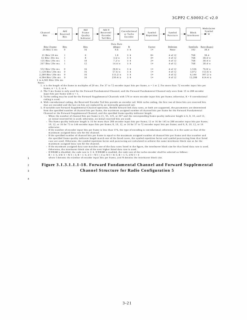
3GPP2 C.S0002-C v2.0
3-21
Data RateBits/Frame Bits Bits (kbps) R Factor Deletion Symbols Rate (ksps)
24 Bits/5 ms 0 16 9.6 1/4 1× None 192 38.4
21 Bits/20 ms 1 6 1.8 1/4 8× 4 of 12 768 38.455 Bits/20n ms 1 8 3.6/n 1/4 4× 4 of 12 768 38.4/n
125 Bits/20n ms 1 10 7.2/n 1/4 2× 4 of 12 768 38.4/n267 Bits/20n ms 1 12 14.4/n 1/4 1× 4 of 12 768 38.4/n
552 Bits/20n ms 0 16 28.8/n 1/4 1× 4 of 12 1,536 76.8/n1,128 Bits/20n ms 0 16 57.6/n 1/4 1× 4 of 12 3,072 153.6/n2,280 Bits/20n ms 0 16 115.2/n 1/4 1× 4 of 12 6,144 307.2/n4,584 Bits/20n ms 0 16 230.4/n 1/4 1× 4 of 12 12,288 614.4/n
1 to 4,583 Bits/20n ms
ChannelBits
Convolutionalor TurboEncoder
SymbolRepetition
SymbolPuncture
BlockInterleaver
AddFrameQuality
Indicator
Add 8Reserved/EncoderTail Bits
AddReserved
BitsW
Notes:1. n is the length of the frame in multiples of 20 ms. For 37 to 72 encoder input bits per frame, n = 1 or 2. For more than 72 encoder input bits per
frame, n = 1, 2, or 4.2. The 5 ms frame is only used for the Forward Fundamental Channel, and the Forward Fundamental Channel only uses from 15 to 288 encoder
input bits per frame with n = 1.3. Turbo coding may be used for the Forward Supplemental Channels with 576 or more encoder input bits per frame; otherwise, K = 9 convolutional
coding is used.4. With convolutional coding, the Reserved/Encoder Tail bits provide an encoder tail. With turbo coding, the first two of these bits are reserved bits
that are encoded and the last six bits are replaced by an internally generated tail.5. If variable-rate Forward Supplemental Channel operation, flexible forward link data rates, or both are supported, the parameters are determined
from the specified number of channel bits per frame, the maximum assigned number of channel bits per frame for the Forward FundamentalChannel or the Forward Supplemental Channel, and the specified frame quality indicator length.
- When the number of channel bits per frame is 21, 55, 125, or 267 and the corresponding frame quality indicator length is 6, 8, 10, and 12,an initial reserved bit is used; otherwise, no initial reserved bits are used.
- The frame quality indicator length is 16 for more than 288 encoder input bits per frame; 12 or 16 for 145 to 288 encoder input bits per frame;10, 12, or 16 for 73 to 144 encoder input bits per frame; 8, 10, 12, or 16 for 37 to 72 encoder input bits per frame; and 6, 8, 10, 12, or 16otherwise.
- If the number of encoder input bits per frame is less than 576, the type of encoding is convolutional; otherwise, it is the same as that of the maximum assigned data rate for the channel.
- If the specified number of channel bits per frame is equal to the maximum assigned number of channel bits per frame and that number andthe specified frame quality indicator length match one of the listed cases, the symbol repetition factor and symbol puncturing from that listedcase are used. Otherwise, the symbol repetition factor and puncturing are calculated to achieve the same interleaver block size as for themaximum assigned data rate for the channel.
- If the maximum assigned data rate matches one of the data rates listed in the figure, the interleaver block size for that listed data rate is used.Otherwise, the interleaver block size of the next higher listed data rate is used.
- If ERAM is disabled, the code rate is 1/4. If ERAM is enabled, the code rate of the turbo encoder shall be selected as follows:R = 1/3, if 8/3 < N/I < 3; R = 1/4, if 3 < N/I < 4 or N/I = 8/3; R = 1/5, if N/I > 4where I denotes the number of encoder input bits per frame, and N denotes the interleaver block size.
ModulationSymbol
1
Figure 3.1.3.1.1.1-18. Forward Fundamental Channel and Forward Supplemental 2
Channel Structure for Radio Configuration 5 3
4

3GPP2 C.S0002-C v2.0
3-22
QPSK/8-PSK/16-QAM
Modulator
SymbolDEMUXI/Q Pairs
1 to N
Q
I
Q
I
Cover by 32-Chip Walsh
Code(WCI_SET[0])
Cover by 32-Chip Walsh
Code(WCI_SET
[N-1])
Q
I
Q
I WalshChipLevel
Summer
Q
I
B
A
Q
ISubpacket
SymbolSelection
Forward PacketData Channel
Information Bits (386,770, 1538, 2306, 3074,
or 3842 Bits)
TurboEncoderR = 1/5
Add 16-BitPacketCRC
Add 6-BitTurbo
Encoder TailAllowance
Encoder Packets
ChannelInterleaver
Long Code Mask Scrambler
1
BasebandFilter
∑
BasebandFilter
s(t)
PNQQ-Channel
PN Sequence1.2288 Mcps
PNII-Channel
PN Sequence1.2288 Mcps
cos(2πfCt)
sin(2πfCt)
Q'
I'
Quadrature Spreading(Complex Multiply)I' = I PNI − Q PNQQ' = I PNQ + Q PNI
B
A
Q
IChannel
Gain Q
I
2
Figure 3.1.3.1.1.1-19. Forward Packet Data Channel Structure 3
for Radio Configuration 10 4
5

3GPP2 C.S0002-C v2.0
3-23
Power control symbol puncturing is on the Forward Fundamental Channels and Forward Dedicated Control Channels only.
W
I and Q Scrambling Bit ExtractorExtract the Pairs at a Rate of
Modulation Symbol Rate/(2 × Scrambling Bit Repetition Factor)
Scrambling Bit Repetition1× Factor for Non-TD
2× Factor for TD
ModulationSymbol Rate
ModulationSymbol Rate
ChannelGain
Signal PointMapping0 → +11 → –1
Forward PowerControl
SubchannelGain
PowerControlSymbol
PuncturePower Control
Bits±1 Values16 Bits per
20 ms Frameor 4 Bits per5 ms Frame
Puncture TimingControl (800 Hz)
X
ModulationSymbol Rate
Decimator
PowerControl
Bit PositionExtractor
Long CodeMask
for User m
Long CodeGenerator(1.2288Mcps)
1
Figure 3.1.3.1.1.1-20. Long Code Scrambling, Power Control, and Signal Point 2
Mapping for Forward Traffic Channels with Radio Configurations 3, 4, and 5 3
4
b) TD Mode
a) Non-TD Mode
DEMUXXI
YI1
YI2DEMUX
DEMUXXQ
YQ1
YQ2
YI1
YI2
YQ1
YQ2
X
XI YI
DEMUX
XQ YQ
YI
YQ
X
The DEMUX functions distribute input symbols sequentially from the top to the bottom output paths. 5
Figure 3.1.3.1.1.1-21. Demultiplexer Structure for Spreading Rate 1 6
7

3GPP2 C.S0002-C v2.0
3-24
Walsh function = ±1 (mapping: ‘0’ → +1, ‘1’ → –1)QOFsign = ±1 sign multiplier QOF mask (mapping: ‘0’ → +1, ‘1’ → –1)Walshrot = ‘0’ or ‘1’ 90º-rotation-enable Walsh function
Walshrot = ‘0’ means no rotationWalshrot = ‘1’ means rotate by 90º
The null QOF has QOFsign = +1 and Walshrot = ‘0’.PNI and PNQ = ±1 I-channel and Q-channel PN sequencesThe null QOF is used for Radio Configurations 1 and 2
BasebandFilter
cos(2πfct)
BasebandFilter
sin(2πfct)
s(t)
Complex Multiplier
–
+I
Q
PNQ
PNI
WalshFunction
YI
YQ
QOFsign
WhenEnabled,Rotateby 90º
(Output–Qin + jIin)
Walshrot
Qin
Iin
Enable
Σ
+
+
Σ
+
+
Σ
1
Figure 3.1.3.1.1.1-22. I and Q Mapping (Non-TD Mode) for Spreading Rate 1 2
3

3GPP2 C.S0002-C v2.0
3-25
Walsh function = ±1 (mapping: ‘0’ → +1, ‘1’ → –1)QOFsign = ±1 sign multiplier QOF mask (mapping: ‘0’ → +1, ‘1’ → –1)Walshrot = ‘0’ or ‘1’ 90º-rotation-enable Walsh function
Walshrot = ‘0’ means no rotationWalshrot = ‘1’ means rotate by 90º
The null QOF has QOFsign = +1 and Walshrot = ‘0’.PNI and PNQ = ±1 I-channel and Q-channel PN sequencess1(t) is associated with the Pilot Channel on W0
64
s2(t) is associated with the Transmit Diversity Pilot Channel on W16128
BasebandFilter
cos(2πfct)
BasebandFilter
sin(2πfct)
s1(t)
Complex Multiplier
–
+
+
+
I
Q
YI1
YQ1
PNQ
PNI
BasebandFilter
cos(2πfct)
BasebandFilter
sin(2πfct)
s2(t)
–
+I
Q
YI2
YQ2
WalshFunction
QOFsign
WhenEnabled,Rotateby 90º
(Output–Qin + jIin)
Walshrot
Qin
Iin
Enable
WalshFunction
QOFsign
WhenEnabled,Rotateby 90º
(Output–Qin + jIin)
Walshrot
Qin
Iin
Enable
SymbolRepetition
(+ +)
SymbolRepetition
(+ – )
SymbolRepetition
(+ +)
SymbolRepetition
(+ – )
Σ
Σ
Σ
+
+
Σ
+
+
Σ
+
+
Σ
1
Figure 3.1.3.1.1.1-23. I and Q Mapping (OTD Mode) for Spreading Rate 1 2
3

3GPP2 C.S0002-C v2.0
3-26
Walsh function = ±1 (mapping: ‘0’ → +1, ‘1’ → –1)QOFsign = ±1 sign multiplier QOF mask (mapping: ‘0’ → +1, ‘1’ → –1)Walshrot = ‘0’ or ‘1’ 90º-rotation-enable Walsh function
Walshrot = ‘0’ means no rotationWalshrot = ‘1’ means rotate by 90º
The null QOF has QOF sign = +1 and Walshrot = ‘0’.PNI and PNQ = ±1 I-channel and Q-channel PN sequencess1(t) is associated with the Pilot Channel on W 0
64
s2(t) is associated with the Transmit Diversity Pilot Channel on W 16128
BasebandFilter
cos(2πfct)
BasebandFilter
sin(2πfct)
s1(t)
Complex Multiplier
I
Q
PNQ
PNI
BasebandFilter
cos(2πfct)
BasebandFilter
sin(2πfct)
s2(t)
–
+
+
+
I
Q
WalshFunction
QOFsign
WhenEnabled,Rotateby 90º
(Output–Qin + jIin)
Walshrot
Qin
Iin
Enable
WalshFunction
QOFsign
WhenEnabled,Rotateby 90º
(Output–Qin + jIin)
Walshrot
Qin
Iin
Enable
Σ
Σ
Σ
Σ
–
+
Σ
+
+
Σ
YI1
SymbolRepetition
(+ +)
YI2
SymbolRepetition
(+ – )
–
+
Σ
YQ1
SymbolRepetition
(+ +)
YQ2
SymbolRepetition
(+ – )
+
+
Σ
YI1
SymbolRepetition
(+ – )
YI2
SymbolRepetition
(+ +)
+
+
Σ
YQ1
SymbolRepetition
(+ – )
YQ2
SymbolRepetition
(+ +)
+
–
Σ
1
Figure 3.1.3.1.1.1-24. I and Q Mapping (STS Mode) for Spreading Rate 1 2
3
3.1.3.1.1.2 Spreading Rate 3 4
The Forward CDMA Channel consists of the channels specified in Table 3.1.3.1.1.2-1. 5
Table 3.1.3.1.1.2-1 states the range of valid channels for each channel type. 6
7

3GPP2 C.S0002-C v2.0
3-27
Table 3.1.3.1.1.2-1. Channel Types for the Forward CDMA Channel 1
for Spreading Rate 3 2
Channel Type Maximum Number
Forward Pilot Channel 1
Auxiliary Pilot Channel Not specified
Sync Channel 1
Broadcast Control Channel 78
Quick Paging Channel 3
Common Power Control Channel 4
Common Assignment Channel 7
Forward Common Control Channel 7
Forward Dedicated Control Channel 1*
Forward Fundamental Channel 1*
Forward Supplemental Channel 2*
* per Forward Traffic Channel
3
Each of these code channels is spread by the appropriate Walsh function or quasi-4
orthogonal function. Each code channel is then spread by a quadrature pair of PN 5
sequences at a fixed chip rate of 1.2288 Mcps. Multiple Forward CDMA Channels may be 6
used within a base station in a frequency division multiplexed manner. 7
If a base station transmits the Forward Common Control Channel on a Forward CDMA 8
Channel, then the base station shall also transmit the Broadcast Control Channel on that 9
Forward CDMA Channel. 10
The structures of the Forward Pilot Channel, Auxiliary Pilot Channels, and Sync Channel 11
for Spreading Rate 3 are shown in Figure 3.1.3.1.1.2-1. The structure of the Broadcast 12
Control Channel for Spreading Rate 3 is shown in Figure 3.1.3.1.1.2-2. The structure of 13
the Quick Paging Channel for Spreading Rate 3 is shown in Figure 3.1.3.1.1.2-3. The 14
structure of the Common Power Control Channel for Spreading Rate 3 is shown in Figure 15
3.1.3.1.1.2-4. The structure of the Common Assignment Channel for Spreading Rate 3 is 16
shown in Figure 3.1.3.1.1.2-5. The structure of the Forward Common Control Channel for 17
Spreading Rate 3 is shown in Figure 3.1.3.1.1.2-6. The structure of the Forward Dedicated 18
Control Channel for Spreading Rate 3 is shown in Figure 3.1.3.1.1.2-7 through Figure 19
3.1.3.1.1.2-10. 20
The Forward Fundamental Channel and Forward Supplemental Channel for Radio 21
Configuration 6 have the overall structure shown in Figure 3.1.3.1.1.2-11. The Forward 22
Fundamental Channel and Forward Supplemental Channel for Radio Configuration 7 have 23
the overall structure shown in Figure 3.1.3.1.1.2-12. The Forward Fundamental Channel 24
and Forward Supplemental Channel for Radio Configuration 8 have the overall structure 25
shown in Figure 3.1.3.1.1.2-13. The Forward Fundamental Channel and Forward 26

3GPP2 C.S0002-C v2.0
3-28
Supplemental Channel for Radio Configuration 9 have the overall structure shown in 1
Figure 3.1.3.1.1.2-14. 2
Long code scrambling, power control, and signal point mapping for Forward Traffic 3
Channels with Radio Configurations 6 though 9 are shown in Figure 3.1.3.1.1.2-15. 4
The symbol demultiplexing and I and Q mappings are shown in Figure 3.1.3.1.1.2-16 and 5
Figure 3.1.3.1.1.2-17. 6
7
a) Pilot Channels
PilotChannels(All 0’s)
ChannelGain
Signal PointMapping0 → +11 → –1
XI
XQ0
b) Sync Channel
SyncChannel
Bits
32 Bits per26.666... ms FrameData Rate 1.2 kbps
ConvolutionalEncoder
R = 1/2, K = 9
SymbolRepetition(2× Factor)
BlockInterleaver
(128Symbols)
4.8 ksps
ChannelGain
Signal PointMapping0 → +11 → –1
YIi
YQi
For Carrier i(i = 1, 2, or 3)
0
ModulationSymbol
4.8 ksps
8
Figure 3.1.3.1.1.2-1. Forward Pilot Channel, Auxiliary Pilot Channels, and Sync 9
Channel for Spreading Rate 3 10
11

3GPP2 C.S0002-C v2.0
3-29
BlockInterleaver
(2,304 Symbols)
Add 16-BitFrameQuality
Indicator
Add 8-BitEncoder
Tail
ConvolutionalEncoder
R = 1/3, K = 9
Broadcast ControlChannel Bits(744 Bits per
40, 80, or 160 msBroadcast Control
Channel Slot) Data Rate19.2, 9.6, or 4.8 kbps
ChannelGain
Signal PointMapping0 → +11 → –1
SequenceRepetition(1, 2, or 4×
Factor)
X57.6 ksps
I and Q Scrambling Bit ExtractorExtract the Pairs at a Rate ofModulation Symbol Rate/6
Scrambling Bit Repetition(3× Factor)
ModulationSymbol Rate
Long CodeMask for
BroadcastControlChannel
Long CodeGenerator(3.6864Mcps)
ModulationSymbol
1
Figure 3.1.3.1.1.2-2. Broadcast Control Channel Structure for Spreading Rate 3 2
3
Quick Paging ChannelIndicators
Indicator Rate 9.6 or 4.8 kspsData Rate 4.8 or 2.4 kbps
SymbolRepetition(3× or 6×Factor)
Signal Point Mapping+1 When Indicator Enabled0 Otherwise
ChannelGain
X28.8 ksps
ModulationSymbol
4
Figure 3.1.3.1.1.2-3. Quick Paging Channel Structure for Spreading Rate 3 5
6

3GPP2 C.S0002-C v2.0
3-30
Long Code Maskfor Common
Power ControlChannel
Long CodeGenerator
(3.6864Mcps)
DecimatorRelativeOffset
Calculation
MUX
MUX
I ArmData Rate= 9.6 kbps
SymbolRepetition(3× Factor)
Signal Point Mapping0 → +11 → –1
No Symbol → 0
I ArmModulation
Symbol28.8 ksps
MUX InputSymbol
Position 2N – 1
MUX InputSymbol
Position 0
MUX InputSymbol
Position N
MUX InputSymbol
Position N – 1Mapto
MUXInput
SymbolPositions
InputPower
ControlBits
SymbolPresentIndicator
Q ArmData Rate= 9.6 kbps
SymbolPresentIndicator
SymbolRepetition(3× Factor)
Q ArmModulation
Symbol28.8 ksps
Signal Point Mapping0 → +11 → –1
No Symbol → 0
ChannelGain XI
ChannelGain XQ
Update Rate N800 bps 12400 bps 24200 bps 48
1
Long Code Maskfor Common
Power ControlChannel
Long CodeGenerator(3.6864Mcps)
DecimatorRelativeOffset
Calculation
Signal Point Mapping0 → +11 → –1
No Symbol → 0
ChannelGain
SymbolRepetition(3× Factor)
MUX
Signal Point Mapping0 → +11 → –1
No Symbol → 0
ChannelGain
SymbolPresent
Indicator
SymbolRepetition(3× Factor)
MUX
XI
XQ
Q ArmModulation Symbol
28.8 ksps
Q ArmData Rate= 9.6 kbps
I ArmModulation Symbol
28.8 ksps
I ArmData Rate= 9.6 kbps Symbol
PresentIndicator
Update Rate N800 bps 12400 bps 24200 bps 48
Q ArmInput
PC Bits
I ArmInput
PC Bits
AssignedInitial
Offset 0
AssignedInitial
Offset N – 1
AssignedInitial
Offset 0
AssignedInitial
Offset N – 1
2
Figure 3.1.3.1.1.2-4. Common Power Control Channel Structure for Spreading Rate 3 3

3GPP2 C.S0002-C v2.0
3-31
1
BlockInterleaver
(144 Symbols)
Add 8-BitFrameQuality
Indicator
Add 8-BitEncoder
Tail
ConvolutionalEncoder
R = 1/3, K = 9
Common AssignmentChannel Bits(32 Bits per5 ms Frame)
Data Rate 9.6 kbps
Signal Point Mapping0 → +11 → –1
No Message → 0
ChannelGain
X
MessagePresent
Indicator
28.8 ksps
I and Q Scrambling Bit ExtractorExtract the Pairs at a Rate ofModulation Symbol Rate/6
Scrambling Bit Repetition(3× Factor)
ModulationSymbol Rate
Long CodeMask forCommon
AssignmentChannel
Long CodeGenerator(3.6864Mcps)
ModulationSymbol
2
Figure 3.1.3.1.1.2-5. Common Assignment Channel Structure for Spreading Rate 3 3
4

3GPP2 C.S0002-C v2.0
3-32
BlockInterleaver
Add 8-BitEncoder
Tail
ConvolutionalEncoder
R = 1/3, K = 9
ForwardCommonControlChannel
Bits
Data Rate RateBits/Frame Bits (kbps) Symbols (ksps)
172 Bits/5 ms 12 38.4 576 115.2172 Bits/10 ms 12 19.2 576 57.6360 Bits/10 ms 16 38.4 1,152 115.2172 Bits/20 ms 12 9.6 576 28.8360 Bits/20 ms 16 19.2 1,152 57.6744 Bits/20 ms 16 38.4 2,304 115.2
ChannelGain
Signal PointMapping0 → +11 → –1
X
I and Q Scrambling Bit ExtractorExtract the Pairs at a Rate ofModulation Symbol Rate/6
Scrambling Bit Repetition(3× Factor)
ModulationSymbol Rate
Long CodeMask for
Forward CommonControl Channel
Long CodeGenerator(3.6864Mcps)
ModulationSymbol
AddFrameQuality
Indicator
1
Figure 3.1.3.1.1.2-6. Forward Common Control Channel Structure 2
for Spreading Rate 3 3
4

3GPP2 C.S0002-C v2.0
3-33
Data RateBits/Frame Bits (kbps) Factor Symbols Rate (ksps)
24 Bits/5 ms 16 9.6 1× 288 57.6172 Bits/20 ms 12 9.6 1× 1,152 57.6
1 to 171 Bits/20 ms 12 or 16 1.05 to 9.55 1,152 57.6
ConvolutionalEncoder
R = 1/6, K = 9
SymbolRepetition
AddFrameQuality
Indicator
Add 8EncoderTail Bits
ForwardDedicatedControlChannel
Bits
BlockInterleaver
ModulationSymbol
Note: If flexible data rates are supported, there can be 1 to 171 channel bits in a 20 ms frame. Symbol repetition factor iscalculated to achieve the interleaver block size of 1,152.
W
1
Data RateBits/Frame Bits (kbps) Symbols Rate (ksps)
24 Bits/5 ms 16 9.6 288 57.6172 Bits/20 ms 12 9.6 1,152 57.6
1 to 171 Bits/20 ms12 or 16 1.05 to 9.55 1,152 57.6
ConvolutionalEncoder
R = 1/6, K = 9
AddFrameQuality
Indicator
Add 8EncoderTail Bits
ForwardDedicatedControlChannel
InformationBits
BlockInterleaver
W
ModulationSymbol
Note: If flexible data rates are supported, there can be 1 to 171 information bits in a 20 ms frameand the encoded symbols will be repeated then punctured to provide a 57.6 ksps modulation symbolrate. 2
Figure 3.1.3.1.1.2-7. Forward Dedicated Control Channel Structure 3
for Radio Configuration 6 4
5

3GPP2 C.S0002-C v2.0
3-34
Data RateBits/Frame Bits (kbps) Factor Symbols Rate (ksps)
24 Bits/5 ms 16 9.6 1× 144 28.8172 Bits/20 ms 12 9.6 1× 576 28.8
1 to 171 Bits/20 ms 12 or 16 1.05 to 9.55 576 28.8
ConvolutionalEncoder
R = 1/3, K = 9
SymbolRepetition
AddFrameQuality
Indicator
Add 8EncoderTail Bits
ForwardDedicatedControlChannel
Bits
BlockInterleaver
ModulationSymbol
Note: If flexible data rates are supported, there can be 1 to 171 channel bits in a 20 ms frame. Symbol repetition factor iscalculated to achieve the interleaver block size of 576.
W
1
Data RateBits/Frame Bits (kbps) Symbols Rate (ksps)
24 Bits/5 ms 16 9.6 144 28.8172 Bits/20 ms 12 9.6 576 28.8
1 to 171 Bits/20 ms 12 or 16 1.05 to 9.55 576 28.8
ConvolutionalEncoder
R = 1/3, K = 9
AddFrameQuality
Indicator
Add 8EncoderTail Bits
ForwardDedicatedControlChannel
InformationBits
BlockInterleaver
W
ModulationSymbol
Note: If flexible data rates are supported, there can be 1 to 171 information bits in a 20 ms frameand the encoded symbols will be repeated then punctured to provide a 28.8 ksps modulation symbolrate. 2
Figure 3.1.3.1.1.2-8. Forward Dedicated Control Channel Structure 3
for Radio Configuration 7 4
5
Data RateBits/Frame Bits Bits (kbps) R Factor Symbols Rate (ksps)
24 Bits/5 ms 0 16 9.6 1/3 2× 288 57.6267 Bits/20 ms 1 12 14.4 1/4 1× 1,152 57.6
1 to 268 Bits/20 ms 0 12 or 16 1.05 to 14.4 1/4 1,152 57.6
ForwardDedicatedControlChannel
Bits
ConvolutionalEncoder
SymbolRepetition
BlockInterleaver
AddFrame Quality
Indicator
Add 8EncoderTail Bits
Add Reserved
Bits
ModulationSymbol
Notes: If flexible data rates are supported, there can be 1 to 268 channel bits in a 20 ms frame. Symbol repetition factor is calculated to achieve the interleaver block size of 1,152.
W
6
Data RateBits/Frame Bits Bits (kbps) R Factor Symbols Rate (ksps)
24 Bits/5 ms 0 16 9.6 1/3 2× 288 57.6267 Bits/20 ms 1 12 14.4 1/4 1× 1,152 57.6
1 to 268 Bits/20 ms 0 12 or 16 1.05 to 14.4 1/4 1,152 57.6
ForwardDedicatedControlChannel
InformationBits
ConvolutionalEncoder
SymbolRepetition
AddFrameQuality
Indicator
Add 8EncoderTail Bits
AddReserved
Bits
BlockInterleaver
W
ModulationSymbol
Note: If flexible data rates are supported, there can be 1 to 268 information bits in a 20 ms frame and the encoded symbols will beadditionally repeated then punctured to provide a 57.6 ksps modulation symbol rate. 7
Figure 3.1.3.1.1.2-9. Forward Dedicated Control Channel Structure 8
for Radio Configuration 8 9
10

3GPP2 C.S0002-C v2.0
3-35
Data RateBits/Frame Bits Bits (kbps) R Factor Symbols Rate (ksps)
24 Bits/5 ms 0 16 9.6 1/3 1× 144 28.8267 Bits/20 ms 1 12 14.4 1/2 1× 576 28.8
1 to 268 Bits/20 ms 0 12 or 16 1.05 to 14.4 1/2 576 28.8
ForwardDedicatedControlChannel
Bits
ConvolutionalEncoder
SymbolRepetition
BlockInterleaver
AddFrameQuality
Indicator
Add 8EncoderTail Bits
AddReserved
Bits
ModulationSymbol
Notes: If flexible data rates are supported, there can be 1 to 268 channel bits in a 20 ms frame. Symbol repetition factor is calculated to achievethe interleaver block size of 576.
W
1
Data RtaeBits/Frame Bits Bits (kbps) R Symbols Rate (ksps)
24 Bits/5 ms 0 16 9.6 1/3 144 28.8267 Bits/20 ms 1 12 14.4 1/2 576 28.8
1 to 268 Bits/20 ms 0 12 or 16 1.05 to 14.4 1/2 576 28.8
ForwardDedicatedControlChannel
InformationBits
ConvolutionalEncoder
AddFrameQuality
Indicator
Add 8EncoderTail Bits
AddReserved
Bits
BlockInterleaver
W
ModulationSymbol
Note: If flexible data rates are supported, there can be 1 to 268 information bits in a 20 ms frame and the encodedsymbols will be repeated then punctured to provide a 28.8 ksps modulation symbol rate.
2
Figure 3.1.3.1.1.2-10. Forward Dedicated Control Channel Structure 3
for Radio Configuration 9 4
5

3GPP2 C.S0002-C v2.0
3-36
Data RateBits/Frame Bits (kbps) R Factor Deletion Symbols Rate (ksps)
24 Bits/5 ms 16 9.6 1/6 1× None 288 57.6
16 Bits/20 ms 6 1.5 1/6 8× 1 of 5 1,152 57.640 Bits/20n ms 6 2.7/n 1/6 4× 1 of 9 1,152 57.6/n80 Bits/20n ms 8 4.8/n 1/6 2× None 1,152 57.6/n172 Bits/20n ms 12 9.6/n 1/6 1× None 1,152 57.6/n
360 Bits/20n ms 16 19.2/n 1/6 1× None 2,304 115.2/n744 Bits/20n ms 16 38.4/n 1/6 1× None 4,608 230.4/n
1,512 Bits/20n ms 16 76.8/n 1/6 1× None 9,216 460.8/n3,048 Bits/20n ms 16 153.6/n 1/6 1× None 18,432 921.6/n6,120 Bits/20n ms 16 307.2/n 1/6 1× None 36,864 1,843.2/n
1 to 6,119 Bits/20n ms
ConvolutionalEncoder
SymbolRepetition
SymbolPuncture
BlockInterleaver
AddFrameQuality
Indicator
Add 8EncoderTail Bits
WChannel
Bits
Notes:1. n is the length of the frame in multiples of 20 ms. For 31 to 54 encoder input bits per frame, n = 1 or 2. For more than 54 encoder
input bits per frame, n = 1, 2, or 4.2. The 5 ms frame is only used for the Forward Fundamental Channel, and the Forward Fundamental Channel only uses from 15 to
192 encoder input bits per frame with n = 1.3. If variable-rate Forward Supplemental Channel operation, flexible forward link data rates, or both are supported, the parameters
are determined from the specified number of channel bits per frame, the maximum assigned number of channel bits per frame forthe Forward Fundamental Channel or the Forward Supplemental Channel, and the specified frame quality indicator length.
- The frame quality indicator length is 16 for more than 192 encoder input bits per frame; 12 or 16 for 97 to 192 encoder inputbits per frame; 8, 12, or 16 for 55 to 96 encoder input bits per frame; and 6, 8, 12, or 16 otherwise.
- The code rate is 1/6.- If the specified number of channel bits per frame is equal to the maximum assigned number of channel bits per frame and that
number and the specified frame quality indicator length match one of the listed cases, the symbol repetition factor and symbolpuncturing from that listed case are used. Otherwise, the symbol repetition factor and puncturing are calculated to achievethe same interleaver block size as for the maximum assigned data rate for the channel.
- If the maximum assigned data rate matches one of the data rates listed in the figure, the interleaver block size for that listeddata rate is used. Otherwise, the interleaver block size of the next higher listed data rate is used. 1
Figure 3.1.3.1.1.2-11. Forward Fundamental Channel and Forward Supplemental 2
Channel Structure for Radio Configuration 6 3
4

3GPP2 C.S0002-C v2.0
3-37
Data RateBits/Frame Bits (kbps) R Factor Deletion Symbols Rate (ksps)
24 Bits/5 ms 16 9.6 1/3 1× None 144 28.8
16 Bits/20 ms 6 1.5 1/3 8× 1 of 5 576 28.840 Bits/20n ms 6 2.7/n 1/3 4× 1 of 9 576 28.8/n80 Bits/20n ms 8 4.8/n 1/3 2× None 576 28.8/n172 Bits/20n ms 12 9.6/n 1/3 1× None 576 28.8/n
360 Bits/20n ms 16 19.2/n 1/3 1× None 1,152 57.6/n744 Bits/20n ms 16 38.4/n 1/3 1× None 2,304 115.2/n
1,512 Bits/20n ms 16 76.8/n 1/3 1× None 4,608 230.4/n3,048 Bits/20n ms 16 153.6/n 1/3 1× None 9,216 460.8/n6,120 Bits/20n ms 16 307.2/n 1/3 1× None 18,432 921.6/n12,264 Bits/20n ms 16 614.4/n 1/3 1× None 36,864 1,843.2/n
1 to 12,263 Bits/20n ms
Convolutionalor TurboEncoder
SymbolRepetition
SymbolPuncture
BlockInterleaver
AddFrameQuality
Indicator
Add 8Reserved/EncoderTail Bits
WChannel
Bits
Notes:1. n is the length of the frame in multiples of 20 ms. For 31 to 54 encoder input bits per frame, n = 1 or 2. For more than 54 encoder
input bits per frame, n = 1, 2, or 4.2. The 5 ms frame is only used for the Forward Fundamental Channel, and the Forward Fundamental Channel only uses from 15 to
192 encoder input bits per frame with n = 1.3. Turbo coding may be used for the Forward Supplemental Channels with 384 or more encoder input bits per frame; otherwise, K =
9 convolutional coding is used.4. With convolutional coding, the Reserved/Encoder Tail bits provide an encoder tail. With turbo coding, the first two of these bits are
reserved bits that are encoded and the last six bits are replaced by an internally generated tail.5. If variable-rate Forward Supplemental Channel operation, flexible forward link data rates, or both are supported, the parameters
are determined from the specified number of channel bits per frame, the maximum assigned number of channel bits per frame forthe Forward Fundamental Channel or the Forward Supplemental Channel, and the specified frame quality indicator length.- The frame quality indicator length is 16 for more than 192 encoder input bits per frame; 12 or 16 for 97 to 192 encoder input
bits per frame; 8, 12, or 16 for 55 to 96 encoder input bits per frame; and 6, 8, 12, or 16 otherwise.- The code rate is 1/3. If the number of encoder input bits per frame is less than 384, the type of encoding is convolutional;
otherwise, it is the same as that of the maximum assigned data rate for the channel.- If the specified number of channel bits per frame is equal to the maximum assigned number of channel bits per frame and that
number and the specified frame quality indicator length match one of the listed cases, the symbol repetition factor and symbolpuncturing from that listed case are used. Otherwise, the symbol repetition factor and puncturing are calculated to achieve thesame interleaver block size as for the maximum assigned data rate for the channel.
- If the maximum assigned data rate matches one of the data rates listed in the figure, the interleaver block size for that listeddata rate is used. Otherwise, the interleaver block size of the next higher listed data rate is used.
ModulationSymbol
1
Figure 3.1.3.1.1.2-12. Forward Fundamental Channel and Forward Supplemental 2
Channel Structure for Radio Configuration 7 3
4

3GPP2 C.S0002-C v2.0
3-38
Data RateBits/Frame Bits Bits (kbps) R Factor Symbols Rate (ksps)
24 Bits/5 ms 0 16 9.6 1/3 2× 288 57.6
21 Bits/20 ms 1 6 1.8 1/4 8× 1,152 57.655 Bits/20n ms 1 8 3.6/n 1/4 4× 1,152 57.6/n125 Bits/20n ms 1 10 7.2/n 1/4 2× 1,152 57.6/n267 Bits/20n ms 1 12 14.4/n 1/4 1× 1,152 57.6/n
552 Bits/20n ms 0 16 28.8/n 1/4 1× 2,304 115.2/n1,128 Bits/20n ms 0 16 57.6/n 1/4 1× 4,608 230.4/n2,280 Bits/20n ms 0 16 115.2/n 1/4 1× 9,216 460.8/n4,584 Bits/20n ms 0 16 230.4/n 1/4 1× 18,432 921.6/n9,192 Bits/20n ms 0 16 460.8/n 1/4 1× 36,864 1,843.2/n
1 to 9,191 Bits/20n ms
ChannelBits
Convolutionalor TurboEncoder
SymbolRepetition
AddFrameQuality
Indicator
Add 8Reserved/EncoderTail Bits
AddReserved
Bits
BlockInterleaver
W
Notes:1. n is the length of the frame in multiples of 20 ms. For 37 to 72 encoder iput bits per frame, n = 1 or 2. For more than 72 encoder
input bits per frame, n = 1, 2, or 4.2. The 5 ms frame is only used for the Forward Fundamental Channel, and the Forward Fundamental Channel only uses from 15 to
288 encoder input bits per frame with n = 1.3. Turbo coding may be used for the Forward Supplemental Channels with 576 or more encoder input bits per frame; otherwise, K =
9 convolutional coding is used.4. With convolutional coding, the Reserved/Encoder Tail bits provide an encoder tail. With turbo coding, the first two of these bits are
reserved bits that are encoded and the last six bits are replaced by an internally generated tail.5. If variable-rate Forward Supplemental Channel operation, flexible forward link data rates, or both are supported, the parameters
are determined from the specified number of channel bits per frame, the maximum assigned number of channel bits per frame forthe Forward Fundamental Channel or the Forward Supplemental Channel, and the specified frame quality indicator length.
- When the number of channel bits per frame is 21, 55, 125, or 267 and the corresponding frame quality indicator length is 6, 8, 10, and 12, an initial reserved bit is used; otherwise, no initial reserved bits are used.
- The frame quality indicator length is 16 for more than 288 encoder input bits per frame; 12 or 16 for 145 to 288 encoder inputbits per frame; 10, 12, or 16 for 73 to 144 encoder input bits per frame; 8, 10, 12, or 16 for 37 to 72 encoder input bits perframe; and 6, 8, 10, 12, or 16 otherwise.
- The code rate is 1/4. If the number of encoder input bits per frame is less than 576, the type of encoding is convolutional;otherwise, it is the same as that of the maximum assigned data rate for the channel.
- If the specified number of channel bits per frame is equal to the maximum assigned number of channel bits per frame andthat number and the specified frame quality indicator length match one of the listed cases, the symbol repetition factor andsymbol puncturing from that listed case are used. Otherwise, the symbol repetition factor and puncturing are calculated toachieve the same interleaver block size as for the maximum assigned data rate for the channel.
- If the maximum assigned data rate matches one of the data rates listed in the figure, the interleaver block size for that listeddata rate is used. Otherwise, the interleaver block size of the next higher listed data rate is used.
ModulationSymbol
1
Figure 3.1.3.1.1.2-13. Forward Fundamental Channel and Forward Supplemental 2
Channel Structure for Radio Configuration 8 3
4

3GPP2 C.S0002-C v2.0
3-39
Data RateBits/Frame Bits Bits (kbps) R Factor Deletion Symbols Rate (ksps)
24 Bits/5 ms 0 16 9.6 1/3 1× None 144 28.8
21 Bits/20 ms 1 6 1.8 1/2 8× None 576 28.855 Bits/20n ms 1 8 3.6/n 1/2 4× None 576 28.8/n
125 Bits/20n ms 1 10 7.2/n 1/2 2× None 576 28.8/n267 Bits/20n ms 1 12 14.4/n 1/2 1× None 576 28.8/n
552 Bits/20n ms 0 16 28.8/n 1/2 1× None 1,152 57.6/n1,128 Bits/20n ms 0 16 57.6/n 1/2 1× None 2,304 115.2/n2,280 Bits/20n ms 0 16 115.2/n 1/2 1× None 4,608 230.4/n4,584 Bits/20n ms 0 16 230.4/n 1/2 1× None 9,216 460.8/n9,192 Bits/20n ms 0 16 460.8/n 1/2 1× None 18,432 921.6/n20,712 Bits/20n ms 0 16 1,036.8/n 1/2 1× 2 of 18 36,864 1,843.2/n
1 to 20,711 Bits/20n ms
ChannelBits
Convolutionalor TurboEncoder
SymbolRepetition
SymbolPuncture
BlockInterleaver
AddFrameQuality
Indicator
Add 8Reserved/EncoderTail Bits
AddReserved
BitsW
Notes:1. n is the length of the frame in multiples of 20 ms. For 37 to 72 encoder input bits per frame, n = 1 or 2. For more than 72 encoder input bits per
frame, n = 1, 2, or 4.2. The 5 ms frame is only used for the Forward Fundamental Channel, and the Forward Fundamental Channel only uses from 15 to 288 encoder input
bits per frame with n = 1.3. Turbo coding may be used for the Forward Supplemental Channels with 576 or more encoder input bits per frame; otherwise, K = 9 convolutional
coding is used.4. With convolutional coding, the Reserved/Encoder Tail bits provide an encoder tail. With turbo coding, the first two of these bits are reserved bits that
are encoded and the last six bits are replaced by an internally generated tail.5. If variable-rate Forward Supplemental Channel operation, flexible forward link data rates, or both are supported, the parameters are determined
from the specified number of channel bits per frame, the maximum assigned number of channel bits per frame for the Forward Fundamental Channelor the Forward Supplemental Channel, and the specified frame quality indicator length.
- When the number of channel bits per frame is 21, 55, 125, or 267 and the corresponding frame quality indicator length is 6, 8, 10, and 12, aninitial reserved bit is used; otherwise, no initial reserved bits are used.
- The frame quality indicator length is 16 for more than 288 encoder input bits per frame; 12 or 16 for 145 to 288 encoder input bits per frame; 10,12, or 16 for 73 to 144 encoder input bits per frame; 8, 10, 12, or 16 for 37 to 72 encoder input bits per frame; and 6, 8, 10, 12, or 16 otherwise.
- The code rate is 1/2. If the number of encoder input bits per frame is less than 576, the type of encoding is convolutional; otherwise, it is thesame as that of the maximum assigned data rate for the channel.
- If the specified number of channel bits per frame is equal to the maximum assigned number of channel bits per frame and that number and thespecified frame quality indicator length match one of the listed cases, the symbol repetition factor and symbol puncturing from that listed caseare used. Otherwise, the symbol repetition factor and puncturing are calculated to achieve the same interleaver block size as for the maximumassigned data rate for the channel.
- If the maximum assigned data rate matches one of the data rates listed in the figure, the interleaver block size for that listed data rateis used. Otherwise, the interleaver block size of the next higher listed data rate is used.
ModulationSymbol
1
Figure 3.1.3.1.1.2-14. Forward Fundamental Channel and Forward Supplemental 2
Channel Structure for Radio Configuration 9 3
4

3GPP2 C.S0002-C v2.0
3-40
Power control symbol puncturing is on the Forward Fundamental Channels and Forward Dedicated Control Channels only.
W
I and Q Scrambling Bit ExtractorExtract the Pairs at a Rate ofModulation Symbol Rate/6
Scrambling Bit Repetition(3× Factor)
ModulationSymbol Rate
ModulationSymbol Rate
ChannelGain
Signal PointMapping0 → +11 → –1
Forward PowerControl
SubchannelGain
PowerControlSymbol
PuncturePower Control
Bits±1 Values16 Bits per
20 ms Frameor 4 Bits per5 ms Frame
Puncture TimingControl (800 Hz)
X
ModulationSymbol Rate
Decimator
PowerControl
Bit PositionExtractor
Long CodeMask
for User m
Long CodeGenerator(3.6864Mcps)
1
Figure 3.1.3.1.1.2-15. Long Code Scrambling, Power Control, and Signal Point 2
Mapping for Forward Traffic Channels with Radio Configurations 6 through 9 3
4
DEMUXXI
DEMUXXQ
YI1YI2YI3
YQ1YQ2YQ3
DEMUXX
YI1YI2YI3YQ1YQ2YQ3
The DEMUX functions distribute input symbols sequentially from the top to thebottom output paths. 5
Figure 3.1.3.1.1.2-16. Demultiplexer Structure for Spreading Rate 3 6
7

3GPP2 C.S0002-C v2.0
3-41
Walsh function = ±1 (mapping: ‘0’ → +1, ‘1’ → –1)QOFsign = ±1 sign multiplier QOF mask (mapping: ‘0’ → +1, ‘1’ → –1)Walshrot = ‘0’ or ‘1’ 90º-rotation-enable Walsh function
Walshrot = ‘0’ means no rotationWalshrot = ‘1’ means rotate by 90º
The null QOF has QOFsign = +1 and Walshrot = ‘0’.PNI and PNQ = ±1 I-channel and Q-channel PN sequencesfc1 < fc2 < fc3
BasebandFilter
cos(2πfc1t)
BasebandFilter
sin(2πfc1t)
s1(t)
Complex Multiplier
–
+
+
+
I
Q
PNQ
PNI
BasebandFilter
cos(2πfc2t)
BasebandFilter
sin(2πfc2t)
s2(t)
–
+
+
+
I
Q
PNQ
PNI
BasebandFilter
cos(2πfc3t)
BasebandFilter
sin(2πfc3t)
s3(t)
–
+I
Q
PNQ
PNI
YI1
YQ1
WalshFunction
QOFsign
WhenEnabled,Rotateby 90º
(Output–Qin + jIin)
Walshrot
Qin
Iin
Enable
YI2
YQ2
WalshFunction
QOFsign
WhenEnabled,Rotateby 90º
(Output–Qin + jIin)
Walshrot
Qin
Iin
Enable
YI3
YQ3
WalshFunction
QOFsign
WhenEnabled,Rotateby 90º
(Output–Qin + jIin)
Walshrot
Qin
Iin
Enable
Σ
Σ
Σ
Σ
Σ
+
+
Σ
+
+
Σ
+
+
Σ
+
+
Σ
1
Figure 3.1.3.1.1.2-17. I and Q Mapping for Spreading Rate 3 2

3GPP2 C.S0002-C v2.0
3-42
3.1.3.1.2 Modulation Parameters 1
3.1.3.1.2.1 Spreading Rate 1 2
The modulation parameters for the Forward CDMA Channel operating in Spreading Rate 1 3
are shown in Table 3.1.3.1.2.1-1 through . 4
5
Table 3.1.3.1.2.1-1. Sync Channel Modulation Parameters for Spreading Rate 1 6
Data Rate (bps)
Parameter 1,200 Units
PN Chip Rate 1.2288 Mcps
Code Rate 1/2 bits/code symbol
Code Symbol Repetition 2 modulation symbols/code symbol
Modulation Symbol Rate 4,800 sps
Walsh Length 64 PN chips
Number of Walsh Function Repetitions per Modulation Symbol
4 Walsh functions/modulation symbol
Processing Gain 1,024 PN chips/bit
7
Table 3.1.3.1.2.1-2. Paging Channel Modulation Parameters for Spreading Rate 1 8
Data Rate (bps)
Parameter 9,600 4,800 Units
PN Chip Rate 1.2288 1.2288 Mcps
Code Rate 1/2 1/2 bits/code symbol
Code Symbol Repetition 1 2 modulation symbols/code symbol
Modulation Symbol Rate 19,200 19,200 sps
Walsh Length 64 64 PN chips
Number of Walsh Function Repetitions per Modulation Symbol
1 1 Walsh functions/ modulation symbol
Processing Gain 128 256 PN chips/bit
9

3GPP2 C.S0002-C v2.0
3-43
Table 3.1.3.1.2.1-3. Broadcast Control Channel Modulation Parameters for Spreading 1
Rate 1 with R = 1/4 2
Data Rate (bps)
Parameter 19,200 9,600 4,800 Units
PN Chip Rate 1.2288 1.2288 1.2288 Mcps
Code Rate 1/4 1/4 1/4 bits/code symbol
Code Sequence Repetition 1 2 4 modulation symbols/ code symbol
Modulation Symbol Rate 76,800 76,800 76,800 sps
QPSK Symbol Rate 38,400 38,400 38,400 sps
Walsh Length 32 32 32 PN chips
Number of Walsh Function Repetitions per QPSK Symbol
1 1 1 Walsh functions/QPSK symbol
Processing Gain 64 128 256 PN chips/bit
3
Table 3.1.3.1.2.1-4. Broadcast Control Channel Modulation Parameters for Spreading 4
Rate 1 with R = 1/2 5
Data Rate (bps)
Parameter 19,200 9,600 4,800 Units
PN Chip Rate 1.2288 1.2288 1.2288 Mcps
Code Rate 1/2 1/2 1/2 bits/code symbol
Code Sequence Repetition 1 2 4 modulation symbols/ code symbol
Modulation Symbol Rate 38,400 38,400 38,400 sps
QPSK Symbol Rate 19,200 19,200 19,200 sps
Walsh Length 64 64 64 PN chips
Number of Walsh Function Repetitions per QPSK Symbol
1 1 1 Walsh functions/QPSK symbol
Processing Gain 64 128 256 PN chips/bit
6

3GPP2 C.S0002-C v2.0
3-44
Table 3.1.3.1.2.1-5. Quick Paging Channel Modulation Parameters 1
for Spreading Rate 1 2
Data Rate (bps)
Parameter 4,800 2,400 Units
PN Chip Rate 1.2288 1.2288 Mcps
Number of Indicators/80 ms Quick Paging Channel Slot
768 384 indicators/slot
Number of Indicators/Slot/ Mobile Station
2 2 indicators/mobile station
Indicator Rate 9,600 4,800 bps
Indicator Repetition Factor 2 4 modulation symbols/ indicator
Modulation Symbol Rate 19,200 19,200 sps
QPSK Symbol Rate 9,600 9,600 sps
Walsh Length 128 128 PN chips
Number of Walsh Function Repetitions per QPSK Symbol
1 1 Walsh functions/QPSK symbol
Processing Gain 256 512 PN chips/mobile station
3
Table 3.1.3.1.2.1-6. Common Power Control Channel Modulation Parameters 4
for Spreading Rate 1 5
Data Rate (bps)
Parameter 19,200 Units
PN Chip Rate 1.2288 Mcps
PC Bit Repetition Factor 1 (non-TD) 2 (TD)
modulation symbols /bit
Modulation Symbol Rate 9,600 (non-TD) 19,200 (TD)
sps on I and Q
Walsh Length 128 (non-TD) 64 (TD)
PN chips
Number of Walsh Function Repetitions per I or Q Arm Modulation Symbol
1 Walsh functions/I or Q arm modulation symbol
Processing Gain 64 PN chips/bit
Note: I and Q arms are considered as separate BPSK channels.
6

3GPP2 C.S0002-C v2.0
3-45
Table 3.1.3.1.2.1-7. Common Assignment Channel Modulation Parameters 1
for Spreading Rate 1 with R = 1/4 2
Data Rate (bps)
Parameter 9,600 Units
PN Chip Rate 1.2288 Mcps
Code Rate 1/4 bits/code symbol
Code Symbol Repetition 1 modulation symbols/code symbol
Modulation Symbol Rate 38,400 sps
QPSK Symbol Rate 19,200 sps
Walsh Length 64 PN chips
Number of Walsh Function Repetitions per QPSK Symbol
1 Walsh functions/QPSK symbol
Processing Gain 128 PN chips/bit
3
Table 3.1.3.1.2.1-8. Common Assignment Channel Modulation Parameters 4
for Spreading Rate 1 with R = 1/2 5
Data Rate (bps)
Parameter 9,600 Units
PN Chip Rate 1.2288 Mcps
Code Rate 1/2 bits/code symbol
Code Symbol Repetition 1 modulation symbols/code symbol
Modulation Symbol Rate 19,200 sps
QPSK Symbol Rate 9,600 sps
Walsh Length 128 PN chips
Number of Walsh Function Repetitions per QPSK Symbol
1 Walsh functions/QPSK symbol
Processing Gain 128 PN chips/bit
6

3GPP2 C.S0002-C v2.0
3-46
Table 3.1.3.1.2.1-9. Forward Common Control Channel Modulation Parameters 1
for Spreading Rate 1 with R = 1/4 2
Data Rate (bps)
Parameter 38,400 19,200 9,600 Units
PN Chip Rate 1.2288 1.2288 1.2288 Mcps
Code Rate 1/4 1/4 1/4 bits/code symbol
Code Symbol Repetition
1 1 1 modulation symbols/code symbol
Modulation Symbol Rate
153,600 76,800 38,400 sps
QPSK Symbol Rate 76,800 38,400 19,200 sps
Walsh Length 16 32 64 PN chips
Number of Walsh Function Repetitions per QPSK Symbol
1 1 1 Walsh functions/QPSK symbol
Processing Gain 32 64 128 PN chips/bit
3
Table 3.1.3.1.2.1-10. Forward Common Control Channel Modulation Parameters 4
for Spreading Rate 1 with R = 1/2 5
Data Rate (bps)
Parameter 38,400 19,200 9,600 Units
PN Chip Rate 1.2288 1.2288 1.2288 Mcps
Code Rate 1/2 1/2 1/2 bits/code symbol
Code Symbol Repetition
1 1 1 modulation symbols/ code symbol
Modulation Symbol Rate
76,800 38,400 19,200 sps
QPSK Symbol Rate 38,400 19,200 9600 sps
Walsh Length 32 64 128 PN chips
Number of Walsh Function Repetitions per QPSK Symbol
1 1 1 Walsh functions/QPSK symbol
Processing Gain 32 64 128 PN chips/bit
6

3GPP2 C.S0002-C v2.0
3-47
Table 3.1.3.1.2.1-11. Forward Packet Data Control Channel Parameters 1
Data Rate (bps)
Parameter 29,600 14,800 7,400 Units
Frame Duration 1.25 2.5 5 ms
PN Chip Rate 1.2288 1.2288 1.2288 Mcps
Code Rate 1/2 1/4 1/4 bits/code symbol
Code Symbol Repetition Rate
1 1 48/37 repeated code symbols/ code symbol
Puncturing Rate 24/37 24/37 1 modulation symbols/repeated code symbol
Modulation Symbol Rate
38,400 38,400 38,400 sps
QPSK Symbol Rate 19,200 19,200 19,200 sps
Walsh Length 64 64 64 PN chips
Number of Walsh Function Repetitions per QPSK Symbol
1 1 1 Walsh functions/QPSK symbol
Processing Gain 41.51 83.03 166.05 PN chips/bit
2
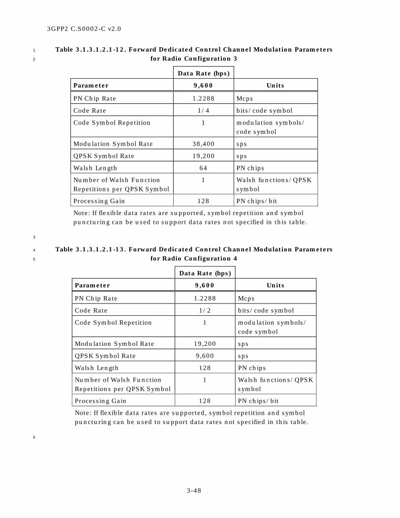
3GPP2 C.S0002-C v2.0
3-48
Table 3.1.3.1.2.1-12. Forward Dedicated Control Channel Modulation Parameters 1
for Radio Configuration 3 2
Data Rate (bps)
Parameter 9,600 Units
PN Chip Rate 1.2288 Mcps
Code Rate 1/4 bits/code symbol
Code Symbol Repetition 1 modulation symbols/ code symbol
Modulation Symbol Rate 38,400 sps
QPSK Symbol Rate 19,200 sps
Walsh Length 64 PN chips
Number of Walsh Function Repetitions per QPSK Symbol
1 Walsh functions/QPSK symbol
Processing Gain 128 PN chips/bit
Note: If flexible data rates are supported, symbol repetition and symbol puncturing can be used to support data rates not specified in this table.
3
Table 3.1.3.1.2.1-13. Forward Dedicated Control Channel Modulation Parameters 4
for Radio Configuration 4 5
Data Rate (bps)
Parameter 9,600 Units
PN Chip Rate 1.2288 Mcps
Code Rate 1/2 bits/code symbol
Code Symbol Repetition 1 modulation symbols/ code symbol
Modulation Symbol Rate 19,200 sps
QPSK Symbol Rate 9,600 sps
Walsh Length 128 PN chips
Number of Walsh Function Repetitions per QPSK Symbol
1 Walsh functions/QPSK symbol
Processing Gain 128 PN chips/bit
Note: If flexible data rates are supported, symbol repetition and symbol puncturing can be used to support data rates not specified in this table.
6

3GPP2 C.S0002-C v2.0
3-49
Table 3.1.3.1.2.1-14. Forward Dedicated Control Channel Modulation Parameters 1
for Radio Configuration 5 2
Data Rate (bps)
Parameter 9,600 14,400 Units
PN Chip Rate 1.2288 1.2288 Mcps
Code Rate 1/4 1/4 bits/code symbol
Code Symbol Repetition 1 1 repeated code symbols/ code symbol
Puncturing Rate 1 8/12 modulation symbols/ repeated code symbol
Modulation Symbol Rate 38,400 38,400 sps
QPSK Symbol Rate 19,200 19,200 sps
Walsh Length 64 64 PN chips
Number of Walsh Function Repetitions per QPSK Symbol
1 1 Walsh functions/QPSK symbol
Processing Gain 128 85.33 PN chips/bit
Notes:
The 9600 bps data rate is used for 5 ms frames and the 14400 bps data rate is used for 20 ms frames.
If flexible data rates are supported, symbol repetition and symbol puncturing can be used to support data rates not specified in this table.
3
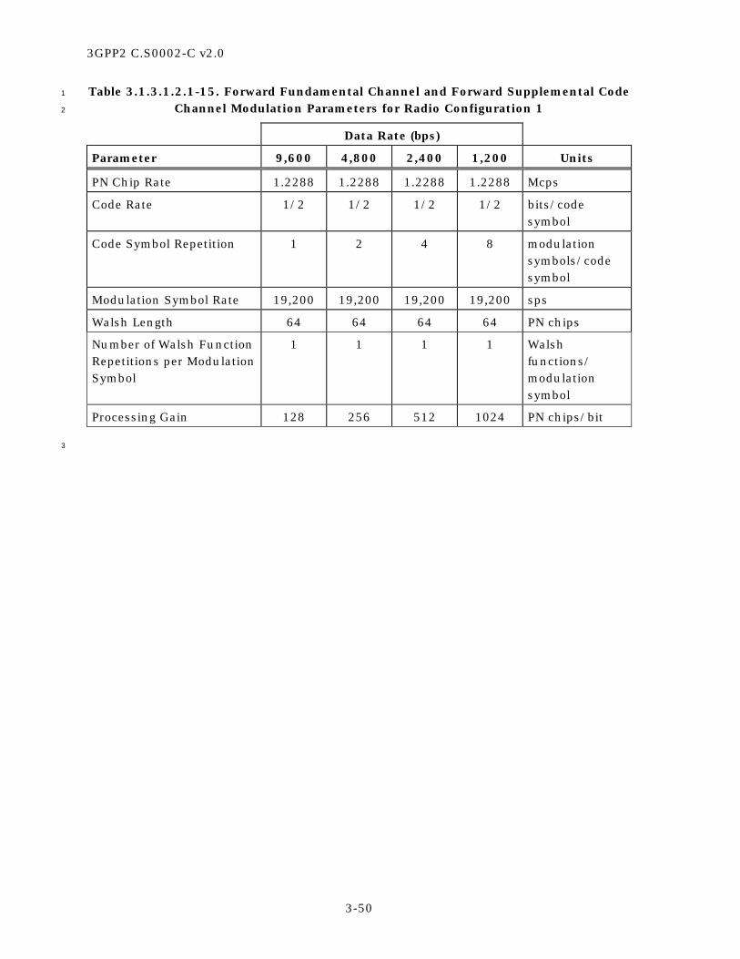
3GPP2 C.S0002-C v2.0
3-50
Table 3.1.3.1.2.1-15. Forward Fundamental Channel and Forward Supplemental Code 1
Channel Modulation Parameters for Radio Configuration 1 2
Data Rate (bps)
Parameter 9,600 4,800 2,400 1,200 Units
PN Chip Rate 1.2288 1.2288 1.2288 1.2288 Mcps
Code Rate 1/2 1/2 1/2 1/2 bits/code symbol
Code Symbol Repetition 1 2 4 8 modulation symbols/code symbol
Modulation Symbol Rate 19,200 19,200 19,200 19,200 sps
Walsh Length 64 64 64 64 PN chips
Number of Walsh Function Repetitions per Modulation Symbol
1 1 1 1 Walsh functions/ modulation symbol
Processing Gain 128 256 512 1024 PN chips/bit
3

3GPP2 C.S0002-C v2.0
3-51
Table 3.1.3.1.2.1-16. Forward Fundamental Channel and Forward Supplemental Code 1
Channel Modulation Parameters for Radio Configuration 2 2
Data Rate (bps)
Parameter 14,400 7,200 3,600 1,800 Units
PN Chip Rate 1.2288 1.2288 1.2288 1.2288 Mcps
Code Rate 1/2 1/2 1/2 1/2 bits/code symbol
Code Symbol Repetition 1 2 4 8 repeated code symbols/ code symbol
Puncturing Rate 4/6 4/6 4/6 4/6 modulation symbols/repeat-ed code symbol
Modulation Symbol Rate 19,200 19,200 19,200 19,200 sps
Walsh Length 64 64 64 64 PN chips
Number of Walsh Function Repetitions per Modulation Symbol
1 1 1 1 Walsh functions/ modulation symbol
Processing Gain 85.33 170.7 341.33 682.7 PN chips/bit
3

3GPP2 C.S0002-C v2.0
3-52
Table 3.1.3.1.2.1-17. Forward Fundamental Channel and Forward Supplemental 1
Channel Modulation Parameters for 5 or 20 ms Frames for Radio Configuration 3 2
Data Rate (bps)
Parameter 9,600 ×××× N 4,800 2,700 1,500 Units
PN Chip Rate 1.2288 1.2288 1.2288 1.2288 Mcps
Code Rate 1/4 1/4 1/4 1/4 bits/code symbol
Code Symbol Repetition
1 2 4 8 repeated code symbols/code symbol
Puncturing Rate 1 1 8/9 4/5 modulation symbols/repeated code symbol
Modulation Symbol Rate
38,400 × N 38,400 38,400 38,400 sps
QPSK Symbol Rate 19,200 × N 19,200 19,200 19,200 sps
Walsh Length 64/N 64 64 64 PN chips
Number of Walsh Function Repetitions per QPSK Symbol
1 1 1 1 Walsh functions/QPSK symbol
Processing Gain 128/N 256 455.1 819.2 PN chips/bit
Notes:
1. N = 1, 2, 4, 8, or 16, which yields data rates of 9600, 19200, 38400, 76800, or 153600 bps, respectively.
2. If variable-rate Forward Supplemental Channel operation, flexible forward link data rates, or both are supported, the parameters are determined from the specified number of channel bits per frame, the maximum assigned number of channel bits per frame for the Forward Fundamental Channel or the Forward Supplemental Channel, and the specified frame quality indicator length.
3

3GPP2 C.S0002-C v2.0
3-53
Table 3.1.3.1.2.1-18. Forward Supplemental Channel Modulation Parameters 1
for 40 ms Frames for Radio Configuration 3 2
Data Rate (bps)
Parameter 9,600 ×××× N 4,800 2,400 1,350 Units
PN Chip Rate 1.2288 1.2288 1.2288 1.2288 Mcps
Code Rate 1/4 1/4 1/4 1/4 bits/code symbol
Code Symbol Repetition
1 1 2 4 repeated code symbols/ code symbol
Puncturing Rate 1 1 1 8/9 interleaver symbols/repeated code symbol
Modulation Symbol Rate
38,400 × N 19,200 19,200 19,200 sps
QPSK Symbol Rate 19,200 × N 9,600 9,600 9,600 sps
Walsh Length 64/N 64 64 64 PN chips
Number of Walsh Function Repetitions per QPSK Symbol
1 2 2 2 Walsh functions/QPSK symbol
Processing Gain 128/N 256 512 910.2 PN chips/bit
Notes:
1. N = 1, 2, 4, or 8, which yields data rates of 9600, 19200, 38400, or 76800 bps, respectively.
2. If variable-rate Forward Supplemental Channel operation, flexible forward link data rates, or both are supported, the parameters are determined from the specified number of channel bits per frame, the maximum assigned number of channel bits per frame for the Forward Supplemental Channel, and the specified frame quality indicator length.
3

3GPP2 C.S0002-C v2.0
3-54
Table 3.1.3.1.2.1-19. Forward Supplemental Channel Modulation Parameters 1
for 80 ms Frames for Radio Configuration 3 2
Data Rate (bps)
Parameter 9,600 ×××× N 4,800 2,400 1,200 Units
PN Chip Rate 1.2288 1.2288 1.2288 1.2288 Mcps
Code Rate 1/4 1/4 1/4 1/4 bits/code symbol
Code Symbol Repetition
1 1 1 2 repeated code symbols/ code symbol
Modulation Symbol Rate
38,400 × N 19,200 9,600 9,600 sps
QPSK Symbol Rate 19,200 × N 9,600 4,800 4,800 sps
Walsh Length 64/N 64 64 64 PN chips
Number of Walsh Function Repetitions per QPSK Symbol
1 2 4 4 Walsh functions/QPSK symbol
Processing Gain 128/N 256 512 1024 PN chips/bit
Notes:
1. N = 1, 2, or 4, which yields data rates of 9600, 19200, or 38400 bps, respectively.
2. If variable-rate Forward Supplemental Channel operation, flexible forward link data rates, or both are supported, the parameters are determined from the specified number of channel bits per frame, the maximum assigned number of channel bits per frame for the Forward Supplemental Channel, and the specified frame quality indicator length.
3

3GPP2 C.S0002-C v2.0
3-55
Table 3.1.3.1.2.1-20. Forward Fundamental Channel and Forward Supplemental 1
Channel Modulation Parameters for 5 or 20 ms Frames for Radio Configuration 4 2
Data Rate (bps)
Parameter 9,600 ×××× N 4,800 2,700 1,500 Units
PN Chip Rate 1.2288 1.2288 1.2288 1.2288 Mcps
Code Rate 1/2 1/2 1/2 1/2 bits/code symbol
Code Symbol Repetition
1 2 4 8 repeated code symbols/ code symbol
Puncturing Rate 1 1 8/9 4/5 modulation symbols/repeated code symbol
Modulation Symbol Rate
19,200 × N 19,200 19,200 19,200 sps
QPSK Symbol Rate 9,600 × N 9,600 9,600 9,600 sps
Walsh Length 128/N 128 128 128 PN chips
Number of Walsh Function Repetitions per QPSK Symbol
1 1 1 1 Walsh functions/QPSK symbol
Processing Gain 128/N 256 455.1 819.2 PN chips/bit
Notes:
1. N = 1, 2, 4, 8, 16, or 32, which yields data rates of 9600, 19200, 38400, 76800, 153600, or 307200 bps, respectively.
2. If variable-rate Forward Supplemental Channel operation, flexible forward link data rates, or both are supported, the parameters are determined from the specified number of channel bits per frame, the maximum assigned number of channel bits per frame for the Forward Fundamental Channel or the Forward Supplemental Channel, and the specified frame quality indicator length.
3

3GPP2 C.S0002-C v2.0
3-56
Table 3.1.3.1.2.1-21. Forward Supplemental Channel Modulation Parameters 1
for 40 ms Frames for Radio Configuration 4 2
Data Rate (bps)
Parameter 9,600 ×××× N 4,800 2,400 1,350 Units
PN Chip Rate 1.2288 1.2288 1.2288 1.2288 Mcps
Code Rate 1/2 1/2 1/2 1/2 bits/code symbol
Code Symbol Repetition
1 1 2 4 repeated code symbols/ code symbol
Puncturing Rate 1 1 1 8/9 interleaver symbols/repeated code symbol
Modulation Symbol Rate
19,200 × N 9,600 9,600 9,600 sps
QPSK Symbol Rate 9,600 × N 4,800 4,800 4,800 sps
Walsh Length 128/N 128 128 128 PN chips
Number of Walsh Function Repetitions per QPSK Symbol
1 2 2 2 Walsh functions/QPSK symbol
Processing Gain 128/N 256 512 910.2 PN chips/bit
Notes:
1. N = 1, 2, 4, 8, or 16, which yields data rates of 9600, 19200, 38400, 76800, or 153600 bps, respectively.
2. If variable-rate Forward Supplemental Channel operation, flexible forward link data rates, or both are supported, the parameters are determined from the specified number of channel bits per frame, the maximum assigned number of channel bits per frame for the Forward Supplemental Channel, and the specified frame quality indicator length.
3

3GPP2 C.S0002-C v2.0
3-57
Table 3.1.3.1.2.1-22. Forward Supplemental Channel Modulation Parameters 1
for 80 ms Frames for Radio Configuration 4 2
Data Rate (bps)
Parameter 9,600 ×××× N 4,800 2,400 1,200 Units
PN Chip Rate 1.2288 1.2288 1.2288 1.2288 Mcps
Code Rate 1/2 1/2 1/2 1/2 bits/code symbol
Code Symbol Repetition
1 1 1 2 repeated code symbols/ code symbol
Modulation Symbol Rate
19,200 × N 9,600 4,800 4,800 sps
QPSK Symbol Rate 9,600 × N 4,800 2,400 2,400 sps
Walsh Length 128/N 128 128 128 PN chips
Number of Walsh Function Repetitions per QPSK Symbol
1 2 4 4 Walsh functions/QPSK symbol
Processing Gain 128/N 256 512 1024 PN chips/bit
Notes:
1. N = 1, 2, 4, or 8, which yields data rates of 9600, 19200, 38400, or 76800 bps, respectively.
2. If variable-rate Forward Supplemental Channel operation, flexible forward link data rates, or both are supported, the parameters are determined from the specified number of channel bits per frame, the maximum assigned number of channel bits per frame for the Forward Supplemental Channel, and the specified frame quality indicator length.
3

3GPP2 C.S0002-C v2.0
3-58
Table 3.1.3.1.2.1-23. Forward Fundamental Channel and Forward Supplemental 1
Channel Modulation Parameters for 20 ms Frames for Radio Configuration 5 2
Data Rate (bps)
Parameter 14,400 ×××× N 7,200 3600 1,800 Units
PN Chip Rate 1.2288 1.2288 1.2288 1.2288 Mcps
Code Rate 1/4 1/4 1/4 1/4 bits/code symbol
Code Symbol Repetition
1 2 4 8 repeated code symbols/ code symbol
Puncturing Rate 8/12 8/12 8/12 8/12 modulation symbols/repeated code symbol
Modulation Symbol Rate
38,400 × N 38,400 38,400 38,400 sps
QPSK Symbol Rate 19,200 × N 19,200 19,200 19,200 sps
Walsh Length 64/N 64 64 64 PN chips
Number of Walsh Function Repetitions per QPSK Symbol
1 1 1 1 Walsh functions/QPSK symbol
Processing Gain 85.33/N 170.7 341.33 682.7 PN chips/bit
Notes:
1. N = 1, 2, 4, 8, or 16, which yields data rates of 14400, 28800, 57600, 115200, or 230400 bps, respectively.
2. If variable-rate Forward Supplemental Channel operation, flexible forward link data rates, or both are supported, the parameters are determined from the specified number of channel bits per frame, the maximum assigned number of channel bits per frame for the Forward Fundamental Channel or the Forward Supplemental Channel, and the specified frame quality indicator length.
3

3GPP2 C.S0002-C v2.0
3-59
Table 3.1.3.1.2.1-24. Forward Supplemental Channel Modulation Parameters 1
for 40 ms Frames for Radio Configuration 5 2
Data Rate (bps)
Parameter 14,400 ×××× N 7,200 3,600 1,800 Units
PN Chip Rate 1.2288 1.2288 1.2288 1.2288 Mcps
Code Rate 1/4 1/4 1/4 1/4 bits/code symbol
Code Symbol Repetition
1 1 2 4 repeated code symbols/ code symbol
Puncturing Rate 8/12 8/12 8/12 8/12 interleaver symbols/repeated code symbol
Modulation Symbol Rate
38,400 × N 19,200 19,200 19,200 sps
QPSK Symbol Rate 19,200 × N 9,600 9,600 9,600 sps
Walsh Length 64/N 64 64 64 PN chips
Number of Walsh Function Repetitions per QPSK Symbol
1 2 2 2 Walsh functions/QPSK symbol
Processing Gain 85.33/N 170.7 341.33 682.7 PN chips/bit
Notes:
1. N = 1, 2, 4, or 8, which yields data rates of 14400, 28800, 57600, or 115200 bps, respectively.
2. If variable-rate Forward Supplemental Channel operation, flexible forward link data rates, or both are supported, the parameters are determined from the specified number of channel bits per frame, the maximum assigned number of channel bits per frame for the Forward Supplemental Channel, and the specified frame quality indicator length.
3
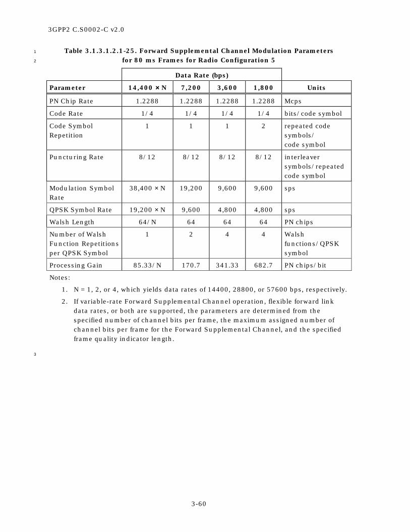
3GPP2 C.S0002-C v2.0
3-60
Table 3.1.3.1.2.1-25. Forward Supplemental Channel Modulation Parameters 1
for 80 ms Frames for Radio Configuration 5 2
Data Rate (bps)
Parameter 14,400 ×××× N 7,200 3,600 1,800 Units
PN Chip Rate 1.2288 1.2288 1.2288 1.2288 Mcps
Code Rate 1/4 1/4 1/4 1/4 bits/code symbol
Code Symbol Repetition
1 1 1 2 repeated code symbols/ code symbol
Puncturing Rate 8/12 8/12 8/12 8/12 interleaver symbols/repeated code symbol
Modulation Symbol Rate
38,400 × N 19,200 9,600 9,600 sps
QPSK Symbol Rate 19,200 × N 9,600 4,800 4,800 sps
Walsh Length 64/N 64 64 64 PN chips
Number of Walsh Function Repetitions per QPSK Symbol
1 2 4 4 Walsh functions/QPSK symbol
Processing Gain 85.33/N 170.7 341.33 682.7 PN chips/bit
Notes:
1. N = 1, 2, or 4, which yields data rates of 14400, 28800, or 57600 bps, respectively.
2. If variable-rate Forward Supplemental Channel operation, flexible forward link data rates, or both are supported, the parameters are determined from the specified number of channel bits per frame, the maximum assigned number of channel bits per frame for the Forward Supplemental Channel, and the specified frame quality indicator length.
3

3GPP2 C.S0002-C v2.0
3-61
Table 3.1.3.1.2.1-26. Forward Fundamental Channel Modulation Parameters 1
for 5 ms Frames for Radio Configuration 5 2
Data Rate (bps)
Parameter 9,600 Units
PN Chip Rate 1.2288 Mcps
Code Rate 1/4 bits/code symbol
Code Symbol Repetition 1 modulation symbols/code symbol
Modulation Symbol Rate 38,400 sps
QPSK Symbol Rate 19,200 sps
Walsh Length 64 PN chips
Number of Walsh Function Repetitions per QPSK Symbol
1 Walsh functions/QPSK symbol
Processing Gain 128 PN chips/bit
3
Table 3.1.3.1.2.1-27. Forward Packet Data Channel Parameters for Radio 4
Configuration 10 5
Please refer to Table 3.1.3.1.13.4-1
6
3.1.3.1.2.2 Spreading Rate 3 7
The modulation parameters for the Forward CDMA Channel operating in Spreading Rate 3 8
are shown in Table 3.1.3.1.2.2-1 through Table 3.1.3.1.2.2-23. 9
10

3GPP2 C.S0002-C v2.0
3-62
Table 3.1.3.1.2.2-1. Sync Channel Modulation Parameters for Spreading Rate 3 1
Data Rate (bps)
Parameter 1,200 Units
PN Chip Rate 1.2288 Mcps
Code Rate 1/2 bits/code symbol
Code Symbol Repetition 2 modulation symbols/code symbol
Modulation Symbol Rate 4,800 sps
Walsh Length 64 PN chips
Number of Walsh Function Repetitions per Modulation Symbol
4 Walsh functions/ modulation symbol
Processing Gain 1,024 PN chips/bit
Note: A Spreading Rate 3 Sync Channel can be transmitted on any of the three carriers.
2
Table 3.1.3.1.2.2-2. Broadcast Control Channel Modulation Parameters for Spreading 3
Rate 3 4
Data Rate (bps)
Parameter 19,200 9,600 4,800 Units
PN Chip Rate 1.2288 1.2288 1.2288 Mcps/carrier
Code Rate 1/3 1/3 1/3 bits/code symbol
Code Sequence Repetition 1 2 4 modulation symbols/code symbol
Modulation Symbol Rate 57,600 57,600 57,600 sps
QPSK Symbol Rate 28,800 28,800 28,800 sps
Walsh Length 128 128 128 PN chips
Number of Walsh Function Repetitions per QPSK Symbol
1 1 1 Walsh functions/QPSK symbol
Processing Gain 192 384 768 PN chips/bit
5

3GPP2 C.S0002-C v2.0
3-63
Table 3.1.3.1.2.2-3. Quick Paging Channel Modulation Parameters for 1
Spreading Rate 3 2
Data Rate (bps)
Parameter 4,800 2,400 Units
PN Chip Rate 1.2288 1.2288 Mcps/carrier
Number of Indicators/80 ms Quick Paging Channel Slot
768 384 indicators/slot
Number of Indicators/Slot/ Mobile Station
2 2 indicators/mobile station
Indicator Rate 9,600 4,800 bps
Indicator Repetition Factor 3 6 modulation symbols/ indicator
Modulation Symbol Rate 28,800 28,800 sps
QPSK Symbol Rate 14,400 14,400 sps
Walsh Length 256 256 PN chips
Number of Walsh Function Repetitions per QPSK Symbol
1 1 Walsh functions/QPSK symbol
Processing Gain 768 1,536 PN chips/mobile station
3
Table 3.1.3.1.2.2-4. Common Power Control Channel Modulation Parameters 4
for Spreading Rate 3 5
Data Rate (bps)
Parameter 19,200 Units
PN Chip Rate 1.2288 Mcps/carrier
PC Bit Repetition Factor 3 modulation symbols /bit
Modulation Symbol Rate 28,800 sps on I and Q
Walsh Length 128 PN chips
Number of Walsh Function Repetitions per QPSK Symbol
1 Walsh functions/QPSK symbol
Processing Gain 192 PN chips/bit
Note: I and Q arms are considered as separate BPSK channels.
6

3GPP2 C.S0002-C v2.0
3-64
Table 3.1.3.1.2.2-5. Common Assignment Channel Modulation Parameters 1
for Spreading Rate 3 2
Data Rate (bps)
Parameter 9,600 Units
PN Chip Rate 1.2288 Mcps/carrier
Code Rate 1/3 bits/code symbol
Code Symbol Repetition 1 modulation symbols/code symbol
Modulation Symbol Rate 28,800 sps
QPSK Symbol Rate 14,400 sps
Walsh Length 256 PN chips
Number of Walsh Function Repetitions per QPSK Symbol
1 Walsh functions/QPSK symbol
Processing Gain 384 PN chips/bit
3
Table 3.1.3.1.2.2-6. Forward Common Control Channel Modulation Parameters 4
for Spreading Rate 3 5
Data Rate (bps)
Parameter 38,400 19,200 9,600 Units
PN Chip Rate 1.2288 1.2288 1.2288 Mcps/carrier
Code Rate 1/3 1/3 1/3 bits/code symbol
Code Symbol Repetition
1 1 1 Modulation symbols/code symbol
Modulation Symbol Rate
115,200 57,600 28,800 sps
QPSK Symbol Rate 57,600 28,800 14,400 sps
Walsh Length 64 128 256 PN chips
Number of Walsh Function Repetitions per QPSK Symbol
1 1 1 Walsh functions/QPSK symbol
Processing Gain 96 192 384 PN chips/bit
6

3GPP2 C.S0002-C v2.0
3-65
Table 3.1.3.1.2.2-7. Forward Dedicated Control Channel Modulation Parameters 1
for Radio Configuration 6 2
Data Rate (bps)
Parameter 9,600 Units
PN Chip Rate 1.2288 Mcps/carrier
Code Rate 1/6 bits/code symbol
Code Symbol Repetition 1 modulation symbols/code symbol
Modulation Symbol Rate 57,600 sps
QPSK Symbol Rate 28,800 sps
Walsh Length 128 PN chips
Number of Walsh Function Repetitions per QPSK Symbol
1 Walsh functions/QPSK symbol
Processing Gain 384 PN chips/bit
Note: If flexible data rates are supported, repetition and puncturing can be used to support data rates not specified in this table.
3
Table 3.1.3.1.2.2-8. Forward Dedicated Control Channel Modulation Parameters 4
for Radio Configuration 7 5
Data Rate (bps)
Parameter 9,600 Units
PN Chip Rate 1.2288 Mcps/carrier
Code Rate 1/3 bits/code symbol
Code Symbol Repetition 1 modulation symbols/code symbol
Modulation Symbol Rate 28,800 sps
QPSK Symbol Rate 14,400 sps
Walsh Length 256 PN chips
Number of Walsh Function Repetitions per QPSK Symbol
1 Walsh functions/QPSK symbol
Processing Gain 384 PN chips/bit
Note: If flexible data rates are supported, repetition and puncturing can be used to support data rates not specified in this table.
6
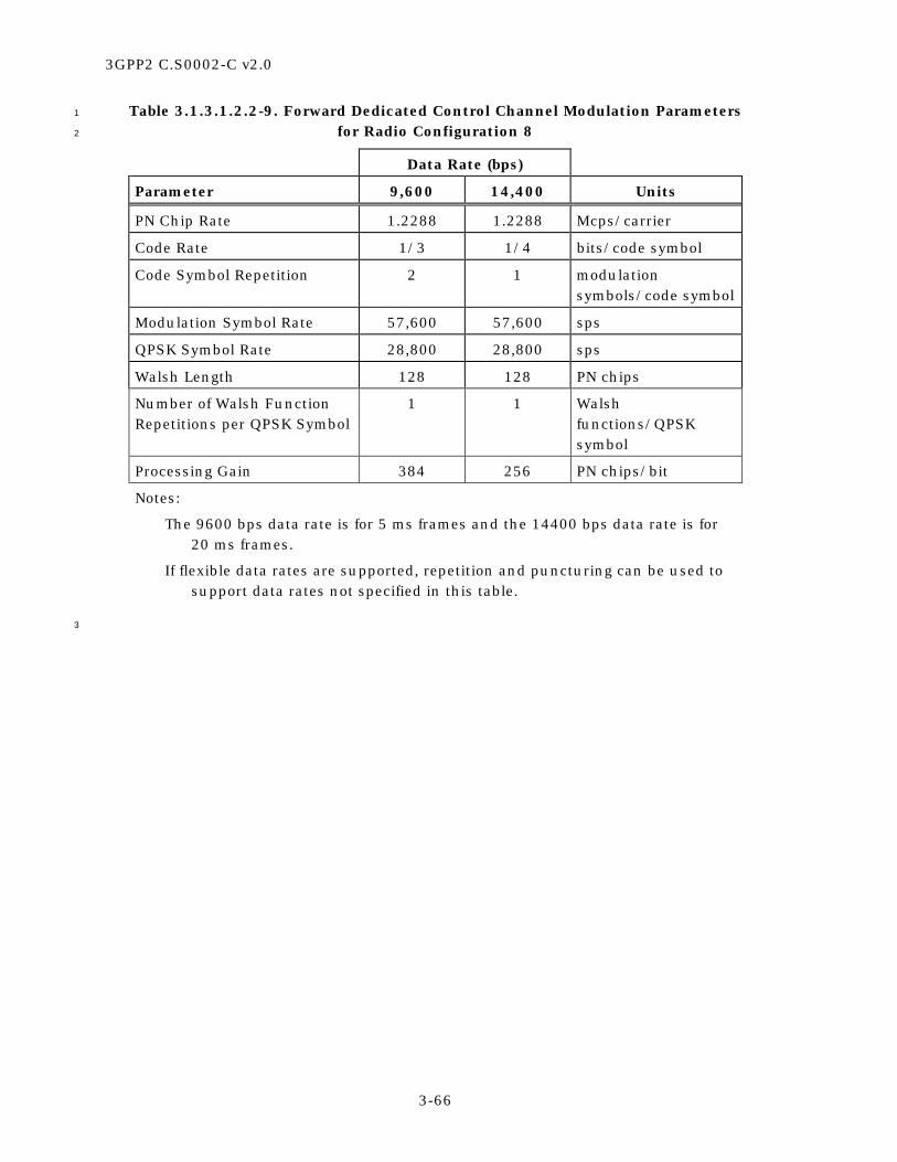
3GPP2 C.S0002-C v2.0
3-66
Table 3.1.3.1.2.2-9. Forward Dedicated Control Channel Modulation Parameters 1
for Radio Configuration 8 2
Data Rate (bps)
Parameter 9,600 14,400 Units
PN Chip Rate 1.2288 1.2288 Mcps/carrier
Code Rate 1/3 1/4 bits/code symbol
Code Symbol Repetition 2 1 modulation symbols/code symbol
Modulation Symbol Rate 57,600 57,600 sps
QPSK Symbol Rate 28,800 28,800 sps
Walsh Length 128 128 PN chips
Number of Walsh Function Repetitions per QPSK Symbol
1 1 Walsh functions/QPSK symbol
Processing Gain 384 256 PN chips/bit
Notes:
The 9600 bps data rate is for 5 ms frames and the 14400 bps data rate is for 20 ms frames.
If flexible data rates are supported, repetition and puncturing can be used to support data rates not specified in this table.
3

3GPP2 C.S0002-C v2.0
3-67
Table 3.1.3.1.2.2-10. Forward Dedicated Control Channel Modulation Parameters 1
for Radio Configuration 9 2
Data Rate (bps)
Parameter 9,600 14,400 Units
PN Chip Rate 1.2288 1.2288 Mcps/carrier
Code Rate 1/3 1/2 bits/code symbol
Code Symbol Repetition 1 1 modulation symbols/code symbol
Modulation Symbol Rate 28,800 28,800 sps
QPSK Symbol Rate 14,400 14,400 sps
Walsh Length 256 256 PN chips
Number of Walsh Function Repetitions per QPSK Symbol
1 1 Walsh functions/QPSK symbol
Processing Gain 384 256 PN chips/bit
Notes:
The 9600 bps data rate is for 5 ms frames and the 14400 bps data rate is for 20 ms frames.
If flexible data rates are supported, repetition and puncturing can be used to support data rates not specified in this table.
3
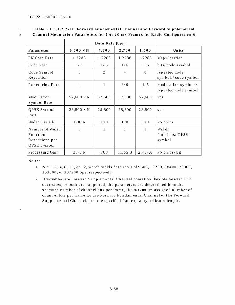
3GPP2 C.S0002-C v2.0
3-68
Table 3.1.3.1.2.2-11. Forward Fundamental Channel and Forward Supplemental 1
Channel Modulation Parameters for 5 or 20 ms Frames for Radio Configuration 6 2
Data Rate (bps)
Parameter 9,600 ×××× N 4,800 2,700 1,500 Units
PN Chip Rate 1.2288 1.2288 1.2288 1.2288 Mcps/carrier
Code Rate 1/6 1/6 1/6 1/6 bits/code symbol
Code Symbol Repetition
1 2 4 8 repeated code symbols/code symbol
Puncturing Rate 1 1 8/9 4/5 modulation symbols/ repeated code symbol
Modulation Symbol Rate
57,600 × N 57,600 57,600 57,600 sps
QPSK Symbol Rate
28,800 × N 28,800 28,800 28,800 sps
Walsh Length 128/N 128 128 128 PN chips
Number of Walsh Function Repetitions per QPSK Symbol
1 1 1 1 Walsh functions/QPSK symbol
Processing Gain 384/N 768 1,365.3 2,457.6 PN chips/bit
Notes:
1. N = 1, 2, 4, 8, 16, or 32, which yields data rates of 9600, 19200, 38400, 76800, 153600, or 307200 bps, respectively.
2. If variable-rate Forward Supplemental Channel operation, flexible forward link data rates, or both are supported, the parameters are determined from the specified number of channel bits per frame, the maximum assigned number of channel bits per frame for the Forward Fundamental Channel or the Forward Supplemental Channel, and the specified frame quality indicator length.
3

3GPP2 C.S0002-C v2.0
3-69
Table 3.1.3.1.2.2-12. Forward Supplemental Channel Modulation Parameters 1
for 40 ms Frames for Radio Configuration 6 2
Data Rate (bps)
Parameter 9,600 ×××× N 4,800 2,400 1,350 Units
PN Chip Rate 1.2288 1.2288 1.2288 1.2288 Mcps/carrier
Code Rate 1/6 1/6 1/6 1/6 bits/code symbol
Code Symbol Repetition
1 1 2 4 repeated code symbols/code symbol
Puncturing Rate 1 1 1 8/9 interleaver symbols/ repeated code symbol
Modulation Symbol Rate
57,600 × N 28,800 28,800 28,800 sps
QPSK Symbol Rate
28,800 × N 14,400 14,400 14,400 sps
Walsh Length 128/N 128 128 128 PN chips
Number of Walsh Function Repetitions per QPSK Symbol
1 2 2 2 Walsh functions/QPSK symbol
Processing Gain 384/N 768 1,536 2,730.7 PN chips/bit
Notes:
1. N = 1, 2, 4, 8, or 16, which yields data rates of 9600, 19200, 38400, 76800, or 153600 bps, respectively.
2. If variable-rate Forward Supplemental Channel operation, flexible forward link data rates, or both are supported, the parameters are determined from the specified number of channel bits per frame, the maximum assigned number of channel bits per frame for the Forward Supplemental Channel, and the specified frame quality indicator length.
3

3GPP2 C.S0002-C v2.0
3-70
Table 3.1.3.1.2.2-13. Forward Supplemental Channel Modulation Parameters 1
for 80 ms Frames for Radio Configuration 6 2
Data Rate (bps)
Parameter 9,600 ×××× N 4,800 2,400 1,200 Units
PN Chip Rate 1.2288 1.2288 1.2288 1.2288 Mcps/carrier
Code Rate 1/6 1/6 1/6 1/6 bits/code symbol
Code Symbol Repetition
1 1 1 2 repeated code symbols/code symbol
Modulation Symbol Rate
57,600 × N 28,800 14,400 14,400 sps
QPSK Symbol Rate
28,800 × N 14,400 7,200 7,200 sps
Walsh Length 128/N 128 128 128 PN chips
Number of Walsh Function Repetitions per QPSK Symbol
1 2 4 4 Walsh functions/QPSK symbol
Processing Gain 384/N 768 1,536 3,072 PN chips/bit
Notes:
1. N = 1, 2, 4, or 8, which yields data rates of 9600, 19200, 38400, or 76800 bps, respectively.
2. If variable-rate Forward Supplemental Channel operation, flexible forward link data rates, or both are supported, the parameters are determined from the specified number of channel bits per frame, the maximum assigned number of channel bits per frame for the Forward Supplemental Channel, and the specified frame quality indicator length.
3

3GPP2 C.S0002-C v2.0
3-71
Table 3.1.3.1.2.2-14. Forward Fundamental Channel and Forward Supplemental 1
Channel Modulation Parameters for 5 or 20 ms Frames for Radio Configuration 7 2
Data Rate (bps)
Parameter 9,600 ×××× N 4,800 2,700 1,500 Units
PN Chip Rate 1.2288 1.2288 1.2288 1.2288 Mcps/carrier
Code Rate 1/3 1/3 1/3 1/3 bits/code symbol
Code Symbol Repetition
1 2 4 8 repeated code symbols/code symbol
Puncturing Rate 1 1 8/9 4/5 modulation symbols/ repeated code symbol
Modulation Symbol Rate
28,800 × N 28,800 28,800 28,800 sps
QPSK Symbol Rate
14,400 × N 14,400 14,400 14,400 sps
Walsh Length 256/N 256 256 256 PN chips
Number of Walsh Function Repetitions per QPSK Symbol
1 1 1 1 Walsh functions/QPSK symbol
Processing Gain 384/N 768 1,365.3 2,457.6 PN chips/bit
Notes:
1. N = 1, 2, 4, 8, 16, 32, or 64, which yields data rates of 9600, 19200, 38400, 76800, 153600, 307200, or 614400 bps, respectively.
2, If variable-rate Forward Supplemental Channel operation, flexible forward link data rates, or both are supported, the parameters are determined from the specified number of channel bits per frame, the maximum assigned number of channel bits per frame for the Forward Fundamental Channel or the Forward Supplemental Channel, and the specified frame quality indicator length.
3

3GPP2 C.S0002-C v2.0
3-72
Table 3.1.3.1.2.2-15. Forward Supplemental Channel Modulation Parameters 1
for 40 ms Frames for Radio Configuration 7 2
Data Rate (bps)
Parameter 9,600 ×××× N 4,800 2,400 1,350 Units
PN Chip Rate 1.2288 1.2288 1.2288 1.2288 Mcps/carrier
Code Rate 1/3 1/3 1/3 1/3 bits/code symbol
Code Symbol Repetition
1 1 2 4 repeated code symbols/code symbol
Puncturing Rate 1 1 1 8/9 modulation symbols/ repeated code symbol
Modulation Symbol Rate
28,800 × N 14,400 14,400 14,400 sps
QPSK Symbol Rate
14,400 × N 7,200 7,200 7,200 sps
Walsh Length 256/N 256 256 256 PN chips
Number of Walsh Function Repetitions per QPSK Symbol
1 2 2 2 Walsh functions/QPSK symbol
Processing Gain 384/N 768 1,536 2,730.7 PN chips/bit
Notes:
1. N = 1, 2, 4, 8, 16, or 32, which yields data rates of 9600, 19200, 38400, 76800, 153600, or 307200 bps, respectively.
2. If variable-rate Forward Supplemental Channel operation, flexible forward link data rates, or both are supported, the parameters are determined from the specified number of channel bits per frame, the maximum assigned number of channel bits per frame for the Forward Supplemental Channel, and the specified frame quality indicator length.
3

3GPP2 C.S0002-C v2.0
3-73
Table 3.1.3.1.2.2-16. Forward Supplemental Channel Modulation Parameters 1
for 80 ms Frames for Radio Configuration 7 2
Data Rate (bps)
Parameter 9,600 ×××× N 4,800 2,400 1,200 Units
PN Chip Rate 1.2288 1.2288 1.2288 1.2288 Mcps/carrier
Code Rate 1/3 1/3 1/3 1/3 bits/code symbol
Code Symbol Repetition
1 1 1 2 repeated code symbols/code symbol
Modulation Symbol Rate
28,800 × N 14,400 7,200 7,200 sps
QPSK Symbol Rate
14,400 × N 7,200 3,600 3,600 sps
Walsh Length 256/N 256 256 256 PN chips
Number of Walsh Function Repetitions per QPSK Symbol
1 2 4 4 Walsh functions/QPSK symbol
Processing Gain 384/N 768 1,536 3,072 PN chips/bit
Notes:
1. N = 1, 2, 4, 8, or 16, which yields data rates of 9600, 19200, 38400, 76800, or 153600 bps, respectively.
2. If variable-rate Forward Supplemental Channel operation, flexible forward link data rates, or both are supported, the parameters are determined from the specified number of channel bits per frame, the maximum assigned number of channel bits per frame for the Forward Supplemental Channel, and the specified frame quality indicator length.
3

3GPP2 C.S0002-C v2.0
3-74
Table 3.1.3.1.2.2-17. Forward Fundamental Channel and Forward Supplemental 1
Channel Modulation Parameters for 20 ms Frames for Radio Configuration 8 2
Data Rate (bps)
Parameter 14,400 ×××× N 7,200 3,600 1,800 Units
PN Chip Rate 1.2288 1.2288 1.2288 1.2288 Mcps/carrier
Code Rate 1/4 1/4 1/4 1/4 bits/code symbol
Code Symbol Repetition 1 2 4 8 repeated code symbols/code symbol
Modulation Symbol Rate 57,600 × N 57,600 57,600 57,600 sps
QPSK Symbol Rate 28,800 × N 28,800 28,800 28,800 sps
Walsh Length 128/N 128 128 128 PN chips
Number of Walsh Function Repetitions per QPSK Symbol
1 1 1 1 Walsh functions/ QPSK symbol
Processing Gain 256/N 512 1,024 2,048 PN chips/bit
Notes:
1. N = 1, 2, 4, 8, 16, or 32, which yields data rates of 14400, 28800, 57600, 115200, 230400, or 460800, respectively.
2. If variable-rate Forward Supplemental Channel operation, flexible forward link data rates, or both are supported, the parameters are determined from the specified number of channel bits per frame, the maximum assigned number of channel bits per frame for the Forward Fundamental Channel or the Forward Supplemental Channel, and the specified frame quality indicator length.
3

3GPP2 C.S0002-C v2.0
3-75
Table 3.1.3.1.2.2-18. Forward Supplemental Channel Modulation Parameters 1
for 40 ms Frames for Radio Configuration 8 2
Data Rate (bps)
Parameter 14,400 ×××× N 7,200 3,600 1,800 Units
PN Chip Rate 1.2288 1.2288 1.2288 1.2288 Mcps/carrier
Code Rate 1/4 1/4 1/4 1/4 bits/code symbol
Code Symbol Repetition 1 1 2 4 repeated code symbols/code symbol
Modulation Symbol Rate 57,600 × N 28,800 28,800 28,800 sps
QPSK Symbol Rate 28,800 × N 14,400 14,400 14,400 sps
Walsh Length 128/N 128 128 128 PN chips
Number of Walsh Function Repetitions per QPSK Symbol
1 2 2 2 Walsh functions/ QPSK symbol
Processing Gain 256/N 512 1,024 2,048 PN chips/bit
Notes:
1. N = 1, 2, 4, 8, or 16, which yields data rates of 14400, 28800, 57600, 115200, or 230400, respectively.
2. If variable-rate Forward Supplemental Channel operation, flexible forward link data rates, or both are supported, the parameters are determined from the specified number of channel bits per frame, the maximum assigned number of channel bits per frame for the Forward Supplemental Channel, and the specified frame quality indicator length.
3

3GPP2 C.S0002-C v2.0
3-76
Table 3.1.3.1.2.2-19. Forward Supplemental Channel Modulation Parameters 1
for 80 ms Frames for Radio Configuration 8 2
Data Rate (bps)
Parameter 14,400 ×××× N 7,200 3,600 1,800 Units
PN Chip Rate 1.2288 1.2288 1.2288 1.2288 Mcps/carrier
Code Rate 1/4 1/4 1/4 1/4 bits/code symbol
Code Symbol Repetition 1 1 1 2 repeated code symbols/code symbol
Modulation Symbol Rate 57,600 × N 28,800 14,400 14,400 sps
QPSK Symbol Rate 28,800 × N 14,400 7,200 7,200 sps
Walsh Length 128/N 128 128 128 PN chips
Number of Walsh Function Repetitions per QPSK Symbol
1 2 4 4 Walsh functions/ QPSK symbol
Processing Gain 256/N 512 1,024 2,048 PN chips/bit
Notes:
1. N = 1, 2, 4, or 8, which yields data rates of 14400, 28800, 57600, or 115200, respectively.
2. If variable-rate Forward Supplemental Channel operation, flexible forward link data rates, or both are supported, the parameters are determined from the specified number of channel bits per frame, the maximum assigned number of channel bits per frame for the Forward Supplemental Channel, and the specified frame quality indicator length.
3

3GPP2 C.S0002-C v2.0
3-77
Table 3.1.3.1.2.2-20. Forward Fundamental Channel and Forward Supplemental 1
Channel Modulation Parameters for 20 ms Frames for Radio Configuration 9 2
Data Rate (bps)
Parameter 14,400 ×××× N 7,200 3,600 1,800 Units
PN Chip Rate 1.2288 1.2288 1.2288 1.2288 Mcps/carrier
Code Rate 1/2 1/2 1/2 1/2 bits/code symbol
Code Symbol Repetition
1 2 4 8 repeated code symbols/code symbol
Puncturing Rate 1 (N ≤ 32) 16/18 (N = 72)
1 1 1 modulation symbols/ repeated code symbol
Modulation Symbol Rate
28,800 × N (N ≤ 32) 1,843,200 (N = 72)
28,800 28,800 28,800 sps
QPSK Symbol Rate
14,400 × N (N ≤ 32) 921,600 (N = 72)
14,400 14,400 14,400 sps
Walsh Length 256/N (N ≤ 32) 4 (N = 72)
256 256 256 PN chips
Number of Walsh Function Repetitions per QPSK Symbol
1 1 1 1 Walsh functions/ QPSK symbol
Processing Gain 256/N 512 1,024 2,048 PN chips/bit
Notes:
1. N = 1, 2, 4, 8, 16, 32, or 72, which yields data rates of 14400, 28800, 57600, 115200, 230400, 460800, or 1036800 bps, respectively.
2. If variable-rate Forward Supplemental Channel operation, flexible forward link data rates, or both are supported, the parameters are determined from the specified number of channel bits per frame, the maximum assigned number of channel bits per frame for the Forward Fundamental Channel or the Forward Supplemental Channel, and the specified frame quality indicator length.
3

3GPP2 C.S0002-C v2.0
3-78
Table 3.1.3.1.2.2-21. Forward Supplemental Channel Modulation Parameters 1
for 40 ms Frames for Radio Configuration 9 2
Data Rate (bps)
Parameter 14,400 ×××× N 7,200 3,600 1,800 Units
PN Chip Rate 1.2288 1.2288 1.2288 1.2288 Mcps/carrier
Code Rate 1/2 1/2 1/2 1/2 bits/code symbol
Code Symbol Repetition
1 1 2 4 repeated code symbols/code symbol
Puncturing Rate 1 (N ≤ 16) 16/18 (N = 36)
1 1 1 interleaver symbols/ repeated code symbol
Modulation Symbol Rate
28,800 × N (N ≤ 16) 921,600 (N = 36)
14,400 14,400 14,400 sps
QPSK Symbol Rate
14,400 × N (N ≤ 16) 460,800 (N = 36)
7,200 7,200 7,200 sps
Walsh Length 256/N (N ≤ 16) 8 (N = 36)
256 256 256 PN chips
Number of Walsh Function Repetitions per QPSK Symbol
1 2 2 2 Walsh functions/ QPSK symbol
Processing Gain 256/N 512 1,024 2,048 PN chips/bit
Notes:
1. N = 1, 2, 4, 8, 16, or 36, which yields data rates of 14400, 28800, 57600, 115200, 230400, or 518400 bps, respectively.
2. If variable-rate Forward Supplemental Channel operation, flexible forward link data rates, or both are supported, the parameters are determined from the specified number of channel bits per frame, the maximum assigned number of channel bits per frame for the Forward Supplemental Channel, and the specified frame quality indicator length.
3

3GPP2 C.S0002-C v2.0
3-79
Table 3.1.3.1.2.2-22. Forward Supplemental Channel Modulation Parameters 1
for 80 ms Frames for Radio Configuration 9 2
Data Rate (bps)
Parameter 14,400 ×××× N 7,200 3,600 1,800 Units
PN Chip Rate 1.2288 1.2288 1.2288 1.2288 Mcps/carrier
Code Rate 1/2 1/2 1/2 1/2 bits/code symbol
Code Symbol Repetition
1 1 1 2 repeated code symbols/code symbol
Puncturing Rate 1 (N ≤ 8) 16/18 (N = 18)
1 1 1 interleaver symbols/ repeated code symbol
Post-Interleaver Symbol Repetition
1 2 4 4 modulation symbols/ interleaver symbol
Modulation Symbol Rate
28,800 × N (N ≤ 8) 460,800 (N = 18)
14,400 7,200 7,200 sps
QPSK Symbol Rate
14,400 × N (N ≤ 8) 230,400 (N = 18)
7,200 3,600 3,600 sps
Walsh Length 256/N (N ≤ 8) 16 (N = 18)
256 256 256 PN chips
Number of Walsh Function Repetitions per QPSK Symbol
1 2 4 4 Walsh functions/ QPSK symbol
Processing Gain 256/N 512 1,024 2,048 PN chips/bit
Notes:
1. N = 1, 2, 4, 8, or 18, which yields data rates of 14400, 28800, 57600, 115200, or 259200 bps, respectively.
2. If variable-rate Forward Supplemental Channel operation, flexible forward link data rates, or both are supported, the parameters are determined from the specified number of channel bits per frame, the maximum assigned number of channel bits per frame for the Forward Supplemental Channel, and the specified frame quality indicator length.
3
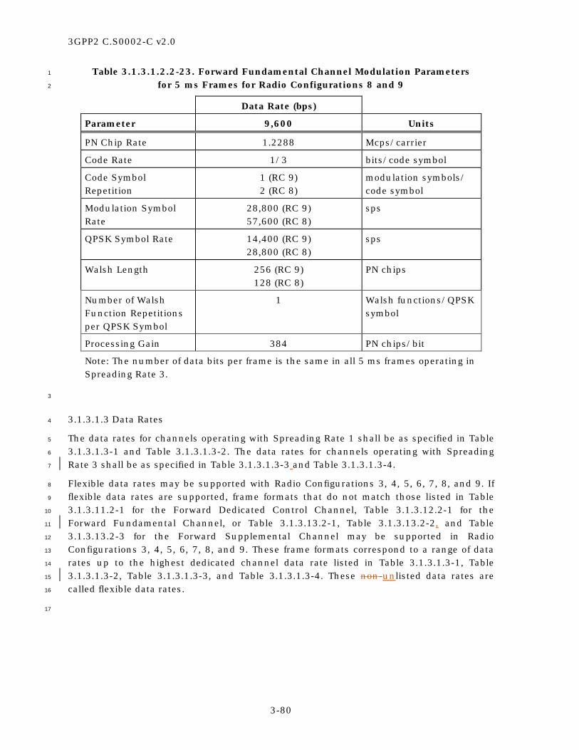
3GPP2 C.S0002-C v2.0
3-80
Table 3.1.3.1.2.2-23. Forward Fundamental Channel Modulation Parameters 1
for 5 ms Frames for Radio Configurations 8 and 9 2
Data Rate (bps)
Parameter 9,600 Units
PN Chip Rate 1.2288 Mcps/carrier
Code Rate 1/3 bits/code symbol
Code Symbol Repetition
1 (RC 9) 2 (RC 8)
modulation symbols/ code symbol
Modulation Symbol Rate
28,800 (RC 9) 57,600 (RC 8)
sps
QPSK Symbol Rate 14,400 (RC 9) 28,800 (RC 8)
sps
Walsh Length 256 (RC 9) 128 (RC 8)
PN chips
Number of Walsh Function Repetitions per QPSK Symbol
1 Walsh functions/QPSK symbol
Processing Gain 384 PN chips/bit
Note: The number of data bits per frame is the same in all 5 ms frames operating in Spreading Rate 3.
3
3.1.3.1.3 Data Rates 4
The data rates for channels operating with Spreading Rate 1 shall be as specified in Table 5
3.1.3.1.3-1 and Table 3.1.3.1.3-2. The data rates for channels operating with Spreading 6
Rate 3 shall be as specified in Table 3.1.3.1.3-3 and Table 3.1.3.1.3-4. 7
Flexible data rates may be supported with Radio Configurations 3, 4, 5, 6, 7, 8, and 9. If 8
flexible data rates are supported, frame formats that do not match those listed in Table 9
3.1.3.11.2-1 for the Forward Dedicated Control Channel, Table 3.1.3.12.2-1 for the 10
Forward Fundamental Channel, or Table 3.1.3.13.2-1, Table 3.1.3.13.2-2, and Table 11
3.1.3.13.2-3 for the Forward Supplemental Channel may be supported in Radio 12
Configurations 3, 4, 5, 6, 7, 8, and 9. These frame formats correspond to a range of data 13
rates up to the highest dedicated channel data rate listed in Table 3.1.3.1.3-1, Table 14
3.1.3.1.3-2, Table 3.1.3.1.3-3, and Table 3.1.3.1.3-4. These non-unlisted data rates are 15
called flexible data rates. 16
17

3GPP2 C.S0002-C v2.0
3-81
Table 3.1.3.1.3-1. Data Rates for Spreading Rate 1 (Part 1 of 2) 1
Channel Type Data Rates (bps)
Sync Channel 1200
Paging Channel 9600 or 4800
Broadcast Control Channel 19200 (40 ms slots), 9600 (80 ms slots), or 4800 (160 ms slots)
Quick Paging Channel 4800 or 2400
Common Power Control Channel 19200 (9600 bps per I and Q arm)
Common Assignment Channel 9600
Forward Common Control Channel 38400 (5, 10 or 20 ms frames), 19200 (10 or 20 ms frames), or
9600 (20 ms frames)
Forward Packet Data Control Channel 29600 (1.25 ms frames) 14800 (2.5 ms frames)
7400 (5 ms frames)
RC 3 or 4 9600 Forward Dedicated Control Channel RC 5 14400 (20 ms frames) or
9600 (5 ms frames)
RC 1 9600, 4800, 2400, or 1200
RC 2 14400, 7200, 3600, or 1800
RC 3 or 4 9600, 4800, 2700, or 1500 (20 ms frames) or 9600 (5 ms frames)
Forward Fundamental Channel
RC 5 14400, 7200, 3600, or 1800 (20 ms frames) or 9600 (5 ms frames)
RC 1 9600 Forward Supplemental Code Channel RC 2 14400
2
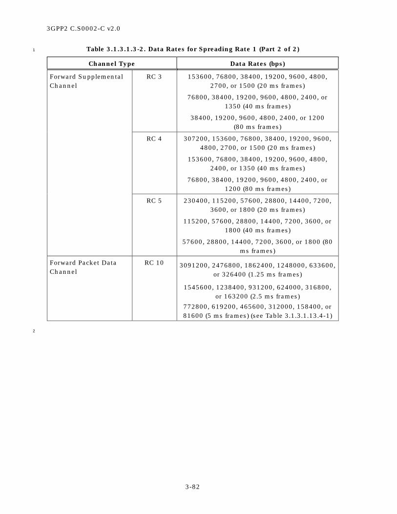
3GPP2 C.S0002-C v2.0
3-82
Table 3.1.3.1.3-2. Data Rates for Spreading Rate 1 (Part 2 of 2) 1
Channel Type Data Rates (bps)
RC 3 153600, 76800, 38400, 19200, 9600, 4800, 2700, or 1500 (20 ms frames)
76800, 38400, 19200, 9600, 4800, 2400, or 1350 (40 ms frames)
38400, 19200, 9600, 4800, 2400, or 1200 (80 ms frames)
RC 4 307200, 153600, 76800, 38400, 19200, 9600, 4800, 2700, or 1500 (20 ms frames)
153600, 76800, 38400, 19200, 9600, 4800, 2400, or 1350 (40 ms frames)
76800, 38400, 19200, 9600, 4800, 2400, or 1200 (80 ms frames)
Forward Supplemental Channel
RC 5 230400, 115200, 57600, 28800, 14400, 7200, 3600, or 1800 (20 ms frames)
115200, 57600, 28800, 14400, 7200, 3600, or 1800 (40 ms frames)
57600, 28800, 14400, 7200, 3600, or 1800 (80 ms frames)
Forward Packet Data Channel
RC 10 3091200, 2476800, 1862400, 1248000, 633600, or 326400 (1.25 ms frames)
1545600, 1238400, 931200, 624000, 316800, or 163200 (2.5 ms frames)
772800, 619200, 465600, 312000, 158400, or 81600 (5 ms frames) (see Table 3.1.3.1.13.4-1)
2

3GPP2 C.S0002-C v2.0
3-83
Table 3.1.3.1.3-3. Data Rates for Spreading Rate 3 (Part 1 of 2) 1
Channel Type Data Rates (bps)
Sync Channel 1200
Broadcast Control Channel 19200 (40 ms slots), 9600 (80 ms slots), or 4800 (160 ms slots)
Quick Paging Channel 4800 or 2400
Common Power Control Channel 19200 (9600 per I and Q arm)
Common Assignment Channel 9600
Forward Common Control Channel 38400 (5, 10 or 20 ms frames), 19200 (10 or 20 ms frames), or
9600 (20 ms frames)
RC 6 or 7 9600 Forward Dedicated Control Channel RC 8 or 9 14400 (20 ms frames) or
9600 (5 ms frames)
RC 6 or 7 9600, 4800, 2700, or 1500 (20 ms frames) or 9600 (5 ms frames)
Forward Fundamental Channel
RC 8 or 9 14400, 7200, 3600, or 1800 (20 ms frames) or 9600 (5 ms frames)
2

3GPP2 C.S0002-C v2.0
3-84
Table 3.1.3.1.3-4. Data Rates for Spreading Rate 3 (Part 2 of 2) 1
Channel Type Data Rates (bps)
RC 6 307200, 153600, 76800, 38400, 19200, 9600, 4800, 2700, or 1500 (20 ms frames)
153600, 76800, 38400, 19200, 9600, 4800, 2400, or 1350 (40 ms frames)
76800, 38400, 19200, 9600, 4800, 2400, or 1200 (80 ms frames)
RC 7 614400, 307200, 153600, 76800, 38400, 19200, 9600, 4800, 2700, or 1500 (20 ms
frames) 307200, 153600, 76800, 38400, 19200,
9600, 4800, 2400, or 1350 (40 ms frames) 153600, 76800, 38400, 19200, 9600, 4800,
2400, or 1200 (80 ms frames)
RC 8 460800, 230400, 115200, 57600, 28800, 14400, 7200, 3600, or 1800 (20 ms frames)
230400, 115200, 57600, 28800, 14400, 7200, 3600, or 1800 (40 ms frames)
115200, 57600, 28800, 14400, 7200, 3600, or 1800 (80 ms frames)
Forward Supplemental Channel
RC 9 1036800, 460800, 230400, 115200, 57600, 28800, 14400, 7200, 3600, or 1800 (20 ms
frames) 518400, 230400, 115200, 57600, 28800,
14400, 7200, 3600, or 1800 (40 ms frames) 259200, 115200, 57600, 28800, 14400,
7200, 3600, or 1800 (80 ms frames)
2
3.1.3.1.4 Forward Error Correction 3
The forward error correction types for channels with Spreading Rate 1 shall be as specified 4
in Table 3.1.3.1.4-1. The forward error correction types for channels with Spreading Rate 3 5
shall be as specified in Table 3.1.3.1.4-2. 6
If the base station supports variable-rate Forward Supplemental Channel operation, 7
flexible data rates, or both, and the specified number of reserved bits, information bits and 8
frame quality indicator bits do not match one of those listed in Table 3.1.3.13.2-1, Table 9
3.1.3.13.2-2, or Table 3.1.3.13.2-3 for the Forward Supplemental Channel, the forward 10
error correction type of the Forward Supplemental Channel shall be the same as that of 11
the maximum assigned number of bits per frame for that channel if, unless turbo code is 12
not available for the specified number of bits per frame, otherwisein which case 13
convolutional code shall be used. The forward error correction code rate of a specified 14
frame format, not listed in Table 3.1.3.13.2-1, Table 3.1.3.13.2-2, or Table 3.1.3.13.2-3 for 15

3GPP2 C.S0002-C v2.0
3-85
the Forward Supplemental Channel, shall be the same as that of the lowest listed data 1
rate in the same radio configuration that is higher than the specified data rate. 2
If ERAM is enabled, the code rate of the turbo encoder shall be selected as follows: 3
• For Radio Configuration 4, the code rate of the turbo encoder shall be 4
=
≤
≤
1/2, if N/I 2
1/3, if 2 < N/I 3R =
1/4, if 3 < N/I 4
1/5, if N/I > 4
5
• For Radio Configuration 5, the code rate of the turbo encoder shall be 6
≤
≤
1/3, if 8/3 < N/I 3
R = 1/4, if 3 < N/I 4 or N/I = 8/3
1/5, if N/I > 4
7
where I denotes the number of encoder input bits per frame and N denotes the interleaver 8
block size. 9
10

3GPP2 C.S0002-C v2.0
3-86
Table 3.1.3.1.4-1. Forward Error Correction for Spreading Rate 1 1
Channel Type Forward Error Correction
R
Sync Channel Convolutional 1/2
Paging Channel Convolutional 1/2
Broadcast Control Channel Convolutional 1/4 or 1/2
Quick Paging Channel None -
Common Power Control Channel None -
Common Assignment Channel Convolutional 1/4 or 1/2
Forward Common Control Channel Convolutional 1/4 or 1/2
Forward Packet Data Control Channel Convolutional 1/2 (1.25 ms frames) 1/4 (2.5 ms frames) 1/4 (5 ms frames)
Forward Dedicated Control Channel Convolutional 1/4 (RC 3 or 5) 1/2 (RC 4)
Forward Fundamental Channel Convolutional 1/2 (RC 1, 2, or 4) 1/4 (RC 3 or 5)
Forward Supplemental Code Channel Convolutional 1/2 (RC 1 or 2)
Convolutional 1/2 (RC 4) 1/4 (RC 3 or 5)
Forward Supplemental Channel
Turbo (N ≥ 360 for RC 3, 4 or N ≥ 552
for RC 5)
1/4 (RC 3) 1/2, 1/3, 1/4 or 1/5 (RC 4)
1/3, 1/4, or 1/5 (RC 5)
Forward Packet Data Channel Turbo 1/5 (RC 10)
Notes:
1. The state of the convolutional encoder shall not be reset between Sync Channel and Paging Channel frames.
2. N is the number of channel bits per frame.
2

3GPP2 C.S0002-C v2.0
3-87
Table 3.1.3.1.4-2. Forward Error Correction for Spreading Rate 3 1
Channel Type Forward Error Correction
R
Sync Channel Convolutional 1/2
Broadcast Control Channel Convolutional 1/3
Quick Paging Channel None -
Common Power Control Channel None -
Common Assignment Channel Convolutional 1/3
Forward Common Control Channel Convolutional 1/3
Forward Dedicated Control Channel Convolutional 1/6 (RC 6); 1/3 (RC 7);
1/4 (RC 8, 20 ms), 1/3 (RC 8, 5 ms); or 1/2 (RC 9, 20 ms), 1/3 (RC 9, 5 ms)
Forward Fundamental Channel Convolutional 1/6 (RC 6); 1/3 (RC 7);
1/4 (RC 8, 20 ms), 1/3 (RC 8, 5 ms); or 1/2 (RC 9, 20 ms), 1/3 (RC 9, 5 ms)
Convolutional 1/6 (RC 6) Forward Supplemental Channel
Convolutional or Turbo (N ≥ 360 for RC 7 or N ≥ 552 for RC 8, 9)
1/3 (RC 7) 1/4 (RC 8) 1/2 (RC 9)
Notes:
1. The state of the convolutional encoder shall not be reset between Sync Channel frames.
2. N is the number of channel bits per frame.
2
3.1.3.1.4.1 Convolutional Encoding 3
All convolutional codes shall have a constraint length of 9. 4
3.1.3.1.4.1.1 Rate 1/6 Convolutional Code 5
The generator functions for the rate 1/6 code shall be g0 equals 457 (octal), g1 equals 755 6
(octal), g2 equals 551 (octal), g3 equals 637 (octal), g4 equals 625 (octal), and g5 equals 727 7
(octal). This code generates six code symbols for each data bit input to the encoder. These 8
code symbols shall be output so that the code symbol (c0) encoded with generator 9
function g0 is output first, the code symbol (c1) encoded with generator function g1 is 10

3GPP2 C.S0002-C v2.0
3-88
output second, the code symbol (c2) encoded with generator function g2 is output third, 1
the code symbol (c3) encoded with generator function g3 is output fourth, the code symbol 2
(c4) encoded with generator function g4 is output fifth, and the code symbol (c5) encoded 3
with generator function g5 is output last. The state of the convolutional encoder, upon 4
initialization, shall be the all-zero state. The first code symbol that is output after 5
initialization shall be a code symbol encoded with generator function g0. 6
Convolutional encoding involves the modulo-2 addition of selected taps of a serially time-7
delayed data sequence. The length of the data sequence delay is equal to K-1, where K is 8
the constraint length of the code. Figure 3.1.3.1.4.1.1-1 illustrates the specific K equals 9, 9
rate 1/6 convolutional encoder that is used for these channels. 10
11
CodeSymbols(Output)
InformationBits
(Input)
c0g0
g1
g2
g3
g4
g5
c1
c2
c3
c4
c5 12
Figure 3.1.3.1.4.1.1-1. K = 9, Rate 1/6 Convolutional Encoder 13
14
3.1.3.1.4.1.2 Rate 1/4 Convolutional Code 15
The generator functions for the rate 1/4 code shall be g0 equals 765 (octal), g1 equals 671 16
(octal), g2 equals 513 (octal), and g3 equals 473 (octal). This code generates four code 17
symbols for each data bit input to the encoder. These code symbols shall be output so that 18
the code symbol (c0) encoded with generator function g0 is output first, the code symbol 19
(c1) encoded with generator function g1 is output second, the code symbol (c2) encoded 20

3GPP2 C.S0002-C v2.0
3-89
with generator function g2 is output third, and the code symbol (c3) encoded with 1
generator function g3 is output last. 2
The state of the convolutional encoder, upon initialization, shall be the all-zero state. The 3
first code symbol that is output after initialization shall be a code symbol encoded with 4
generator function g0. 5
Convolutional encoding involves the modulo-2 addition of selected taps of a serially time-6
delayed data sequence. The length of the data sequence delay is equal to K-1, where K is 7
the constraint length of the code. Figure 3.1.3.1.4.1.2-1 illustrates the specific K equals 9, 8
rate 1/4 convolutional encoder that is used for these channels. 9
10
CodeSymbols(Output)
InformationBits
(Input)
g0c0
g1
g2
g3
c1
c2
c3 11
Figure 3.1.3.1.4.1.2-1. K = 9, Rate 1/4 Convolutional Encoder 12
13
3.1.3.1.4.1.3 Rate 1/3 Convolutional Code 14
The generator functions for the rate 1/3 code shall be g0 equals 557 (octal), g1 equals 663 15
(octal), and g2 equals 711 (octal). This code generates three code symbols for each data bit 16
that is input to the encoder. These code symbols shall be output so that the code symbol 17
(c0) encoded with generator function g0 is output first, the code symbol (c1) encoded with 18
generator function g1 is output second, and the code symbol (c2) encoded with generator 19
function g2 is output last. The state of the convolutional encoder, upon initialization, shall 20
be the all-zero state. The first code symbol that is output after initialization shall be a code 21
symbol encoded with generator function g0. 22
Convolutional encoding involves the modulo-2 addition of selected taps of a serially time-23
delayed data sequence. The length of the data sequence delay is equal to K-1, where K is 24
the constraint length of the code. Figure 3.1.3.1.4.1.3-1 illustrates the specific K equals 9, 25
rate 1/3 convolutional encoder that is used for these channels. 26

3GPP2 C.S0002-C v2.0
3-90
1
CodeSymbols(Output)
InformationBits
(Input)
g0
g1
g2
c0
c1
c2 2
Figure 3.1.3.1.4.1.3-1. K = 9, Rate 1/3 Convolutional Encoder 3
4
3.1.3.1.4.1.4 Rate 1/2 Convolutional Code 5
The generator functions for the rate 1/2 code shall be g0 equals 753 (octal) and g1 equals 6
561 (octal). This code generates two code symbols for each data bit that is input to the 7
encoder. These code symbols shall be output so that the code symbol (c0) encoded with 8
generator function g0 is output first, and the code symbol (c1) encoded with generator 9
function g1 is output last. The state of the convolutional encoder, upon initialization, shall 10
be the all-zero state. The first code symbol that is output after initialization shall be a code 11
symbol encoded with generator function g0. 12
Convolutional encoding involves the modulo-2 addition of selected taps of a serially time-13
delayed data sequence. The length of the data sequence delay is equal to K-1, where K is 14
the constraint length of the code. Figure 3.1.3.1.4.1.4-1 illustrates the specific K equals 9, 15
rate 1/2 convolutional encoder that is used for these channels. 16
17
CodeSymbols(Output)
InformationBits
(Input)
g0
g1
c0
c1 18
Figure 3.1.3.1.4.1.4-1. K = 9, Rate 1/2 Convolutional Encoder 19
20

3GPP2 C.S0002-C v2.0
3-91
3.1.3.1.4.2 Turbo Encoding 1
For Radio Configurations 3 through 9, the turbo encoder encodes the data, frame quality 2
indicator (CRC), and two reserved bits. For the Radio Configuration 10, the turbo encoder 3
encodes the information bits and the frame quality indicator bits. During encoding, an 4
encoder output tail sequence is added. For Radio Configurations 3 through 9, Nturbo is 5
the total number of data, frame quality indicator, and reserved input bits, and for Radio 6
Configuration 10 Nturbo is the total number of information bits and frame quality indicator 7
bits. Then, the turbo encoder generates Nturbo/R encoded data output symbols followed 8
by 6/R tail output symbols, where R is the code rate of 1/2, 1/3, 1/4, or 1/5. The turbo 9
encoder employs two systematic, recursive, convolutional encoders connected in parallel, 10
with an interleaver, the turbo interleaver, preceding the second recursive convolutional 11
encoder. The two recursive convolutional codes are called the constituent codes of the 12
turbo code. The outputs of the constituent encoders are punctured and repeated to 13
achieve the (Nturbo + 6)/R output symbols. 14
3.1.3.1.4.2.1 Rate 1/2, 1/3, 1/4, and 1/5 Turbo Encoders 15
A common constituent code shall be used for the turbo codes of rate 1/2, 1/3, 1/4, and 16
1/5. The transfer function for the constituent code shall be 17
0 1n (D) n (D)G(D) 1
d(D) d(D)
=
18
where d(D) = 1 + D2 + D3, n0(D) = 1 + D + D3, and n1(D) = 1 + D + D2 + D3. 19
The turbo encoder shall generate an output symbol sequence that is identical to the one 20
generated by the encoder shown in Figure 2.1.3.1.4.2.1-1. Initially, the states of the 21
constituent encoder registers in this figure are set to zero. Then, the constituent encoders 22
are clocked with the switches in the positions noted. 23
When Code Combining Soft Handoff is enabled, the base station may be configured to use 24
either the default turbo encoder or the complementary turbo encoder. When Code 25
Combining Soft Handoff is not enabled, the base station shall use the default turbo 26
encoder. For a base station using the default turbo encoder, the constituent encoder 27
output symbols are generated by clocking the constituent encoders Nturbo times with the 28
switches in the up positions and puncturing as specified in Table 3.1.3.1.4.2.1-1. For a 29
base station using the complementary turbo encoder, the constituent encoder output 30
symbols are generated by clocking the constituent encoders Nturbo times with the 31
switches in the up positions and puncturing as specified in Table 3.1.3.1.4.2.1-2. Within a 32
puncturing pattern, a ‘0’ means that the symbol shall be deleted and a ‘1’ means that a 33
symbol shall be passed. 34
The turbo encoder shall generate symbols for rate 1/2 turbo codes as follows. 35
• The symbols output by the default encoder for even-indexed data bit periods shall 36
be XY0. 37
• The symbols output by the default encoder for odd-indexed data bit periods shall 38
be XY′0. 39

3GPP2 C.S0002-C v2.0
3-92
• The symbols output by the complementary encoder for even-indexed data bit 1
periods shall be XY′0. 2
• The symbols output by the complementary encoder for odd-indexed data bit 3
periods shall be XY0. 4
The turbo encoder shall generate symbols for rate 1/3 turbo codes as follows. 5
• The symbols output by the default encoder for all data bit periods shall be XY0Y′0. 6
• The symbols output by the complementary encoder for all data bit periods shall be 7
XY′0Y0. 8
The turbo encoder shall generate symbols for rate 1/4 turbo codes as follows. 9
• The symbols output by the default encoder for even-indexed data bit periods shall 10
be XY0Y1Y′1. 11
• The symbols output by the default encoder for odd-indexed data bit periods shall 12
be XY0Y′0Y′1. 13
• The symbols output by the complementary encoder for even-indexed data bit 14
periods shall be XY′0Y′1Y1. 15
• The symbols output by the complementary encoder for odd-indexed data bit 16
periods shall be XY′0Y0Y1. 17
The turbo encoder shall generate symbols for rate 1/5 turbo codes as follows. 18
• The symbols output by the default encoder for all data bit periods shall be 19
XY0Y1Y′0Y′1. 20
• The symbols output by the complementary encoder for all data bit periods shall be 21
XY′0Y′1Y0Y1. 22
Symbol repetition is not used in generating the encoded data output symbols. 23
24

3GPP2 C.S0002-C v2.0
3-93
TurboInterleaver
X'
Y'0
Y'1
Constituent Encoder 2
n1
n0
d
Clocked once for each of the Nturbo bit periods with the switch up;then, not clocked for the three Constituent Encoder 1
tail bit periods; then, clocked once for each of the threeConstituent Encoder 2 tail bit periods with the switch down.
Control
X
Y0
Y1
Constituent Encoder 1
n1
n0
d
Clocked once for each of the Nturbo bit periods with the switch up;then, clocked once for each of the three Constituent Encoder 1 tailbit periods with the switch down; then, not clocked for the three
Constituent Encoder 2 tail bit periods.
ControlSymbol
Punctureand
Repetition
NturboBits
(Input)
(Nturbo + 6)/RCode
Symbols(Output)
1
Figure 3.1.3.1.4.2.1-1. Turbo Encoder 2
3

3GPP2 C.S0002-C v2.0
3-94
Table 3.1.3.1.4.2.1-1. Puncturing Patterns for the Default Turbo Encoder During the 1
Data Bit Periods 2
Code Rate
Output 1/2 1/3 1/4 1/5
X 11 11 11 11
Y0 10 11 11 11
Y1 00 00 10 11
X′ 00 00 00 00
Y′0 01 11 01 11
Y′1 00 00 11 11
Note: For each rate, the puncturing table shall be read first from top tobottom and then from left to right.
3
Table 3.1.3.1.4.2.1-2. Puncturing Patterns for the Complementary Turbo Encoder 4
During the Data Bit Periods 5
Code Rate
Output 1/2 1/3 1/4 1/5
X 11 11 11 11
Y′0 10 11 11 11
Y′1 00 00 10 11
X′ 00 00 00 00
Y0 01 11 01 11
Y′1 00 00 11 11
Note:
1. For each rate, the puncturing table shall be read first from top to bottom and then from left to right.
2. For R = 1/3 and 1/5, the puncturing patterns do not result in complementary turbo codes.
6
3.1.3.1.4.2.2 Turbo Code Termination 7
The turbo encoder shall generate 6/R tail output symbols following the encoded data 8
output symbols. This tail output symbol sequence shall be identical to the one generated 9
by the encoder shown in Figure 3.1.3.1.4.2.1-1. The tail output symbols are generated 10
after the constituent encoders have been clocked Nturbo times with the switches in the up 11

3GPP2 C.S0002-C v2.0
3-95
position. The first 3/R tail output symbols are generated by clocking Constituent Encoder 1
1 three times with its switch in the down position while Constituent Encoder 2 is not 2
clocked and puncturing and repeating the resulting constituent encoder output symbols. 3
The last 3/R tail output symbols are generated by clocking Constituent Encoder 2 three 4
times with its switch in the down position while Constituent Encoder 1 is not clocked and 5
puncturing and repeating the resulting constituent encoder output symbols. The 6
constituent encoder outputs for each bit period shall be output in the sequence X, Y0, Y1, 7
X′, Y′0, Y′1 with the X output first. 8
The tail output symbol puncturing and symbol repetition used by both the default and 9
complementary turbo encoders shall be as specified in Table 3.1.3.1.4.2.2-1. Within a 10
puncturing pattern, a ‘0’ means that the symbol shall be deleted and a ‘1’ means that a 11
symbol shall be passed. A 2 or a 3 means that two or three copies of the symbol shall be 12
passed. For rate 1/2 turbo codes, the tail output symbols for each of the first three tail bit 13
periods shall be XY0, and the tail output symbols for each of the last three tail bit periods 14
shall be X′Y′0. For rate 1/3 turbo codes, the tail output symbols for each of the first three 15
tail bit periods shall be XXY0, and the tail output symbols for each of the last three tail bit 16
periods shall be X′X′Y′0. For rate 1/4 turbo codes, the tail output symbols for each of the 17
first three tail bit periods shall be XXY0Y1, and the tail output symbols for each of the last 18
three tail bit periods shall be X′X′Y′0Y′1. For rate 1/5 turbo codes, the tail output symbols 19
for each of the first three tail bit periods shall be XXXY0Y1, and the tail output symbols for 20
each of the last three tail bit periods shall be X′X′X′Y′0Y′1. 21
22
Table 3.1.3.1.4.2.2-1. Puncturing and Symbol Repetition Patterns for the Default and 23
Complementary Turbo Encoders During the Tail Bit Periods 24
Code Rate
Output 1/2 1/3 1/4 1/5
X 111 000 222 000 222 000 333 000
Y0 111 000 111 000 111 000 111 000
Y1 000 000 000 000 111 000 111 000
X′ 000 111 000 222 000 222 000 333
Y′0 000 111 000 111 000 111 000 111
Y′1 000 000 000 000 000 111 000 111
Note:
1. The puncturing table shall be read first from top to bottom and then from left to right with the number of repetitions for each symbol indicated by the number in the table.
2. For R = 1/3 and 1/5, the puncturing patterns do not result in complementary turbo codes.
25

3GPP2 C.S0002-C v2.0
3-96
3.1.3.1.4.2.3 Turbo Interleavers 1
The turbo interleaver, which is part of the turbo encoder, shall block interleave the Nturbo 2
input bits. 3
The turbo interleaver shall be functionally equivalent to an approach where the entire 4
sequence of turbo interleaver input bits are written sequentially into an array at a 5
sequence of addresses, and then the entire sequence is read out from a sequence of 6
addresses that are defined by the procedure described below. 7
Let the sequence of input addresses be from 0 to Nturbo – 1. Then, the sequence of 8
interleaver output addresses shall be equivalent to those generated by the procedure 9
illustrated in Figure 3.1.3.1.4.2.3-1 and described below:23 10
1. Determine the turbo interleaver parameter, n, where n is the smallest integer such 11
that Nturbo ≤ 2n + 5. Table 3.1.3.1.4.2.3-1 gives this parameter. 12
2. Initialize an (n + 5)-bit counter to 0. 13
3. Extract the n most significant bits (MSBs) from the counter and add one to form a 14
new value. Then, discard all except the n least significant bits (LSBs) of this value. 15
4. Obtain the n-bit output of the table lookup defined in Table 3.1.3.1.4.2.3-2 with a 16
read address equal to the five LSBs of the counter. Note that this table depends 17
upon the value of n. 18
5. Multiply the values obtained in Steps 3 and 4, and discard all except the n LSBs. 19
6. Bit-reverse the five LSBs of the counter. 20
7. Form a tentative output address that has its MSBs equal to the value obtained in 21
Step 6 and its LSBs equal to the value obtained in Step 5. 22
8. Accept the tentative output address as an output address if it is less than Nturbo; 23
otherwise, discard it. 24
9. Increment the counter and repeat Steps 3 through 8 until all Nturbo interleaver 25
output addresses are obtained. 26
27
23 This procedure is equivalent to one in which the counter values are written into a 25-row by
2n-column array by rows, the rows are shuffled according to a bit-reversal rule, the elements within
each row are permuted according to a row-specific linear congruential sequence, and tentative
output addresses are read out by column. For i = 0, 1, …, 2n-1, tThe linear congruential sequence
rule is x(i + 1) = (x(i) + (i+1)c) mod 2n, where x(0) = c and c is a row-specific value from a table
lookup.

3GPP2 C.S0002-C v2.0
3-97
Add 1and
Select then LSBs
TableLookup
BitReverse
Multiplyand
Select then LSBs
(i0…i4)
n Bits
n Bitsn MSBs
5 Bits
n Bits
5 LSBs
(tn – 1…t0)
(i4…i0)
(in + 4…i5)
(n + 5)-BitCounter
Next(5 + n)-BitInterleaver
OutputAddress
(i0…i4tn – 1…t0)
DiscardIf
Input ≥Nturbo
MSBs
LSBs
1
Figure 3.1.3.1.4.2.3-1. Turbo Interleaver Output Address Calculation Procedure 2
3
Table 3.1.3.1.4.2.3-1. Turbo Interleaver Parameters 4
Turbo Interleaver Block Size
Nturbo
Turbo Interleaver Parameter
n
378 4
402 4
570 5
762 5
786 5
1,146 6
1,530 6
1,554 6
2,298 7
2,322 7
3,066 7
3,090 7
3,858 7
4,602 8
6,138 8
9,210 9
12,282 9
20,730 10
5

3GPP2 C.S0002-C v2.0
3-98
Table 3.1.3.1.4.2.3-2. Turbo Interleaver Lookup Table Definition 1
Table Index
n = 4 Entries
n = 5 Entries
n = 6 Entries
n = 7 Entries
n = 8 Entries
n = 9 Entries
n = 10 Entries
0 5 27 3 15 3 13 1
1 15 3 27 127 1 335 349
2 5 1 15 89 5 87 303
3 15 15 13 1 83 15 721
4 1 13 29 31 19 15 973
5 9 17 5 15 179 1 703
6 9 23 1 61 19 333 761
7 15 13 31 47 99 11 327
8 13 9 3 127 23 13 453
9 15 3 9 17 1 1 95
10 7 15 15 119 3 121 241
11 11 3 31 15 13 155 187
12 15 13 17 57 13 1 497
13 3 1 5 123 3 175 909
14 15 13 39 95 17 421 769
15 5 29 1 5 1 5 349
16 13 21 19 85 63 509 71
17 15 19 27 17 131 215 557
18 9 1 15 55 17 47 197
19 3 3 13 57 131 425 499
20 1 29 45 15 211 295 409
21 3 17 5 41 173 229 259
22 15 25 33 93 231 427 335
23 1 29 15 87 171 83 253
24 13 9 13 63 23 409 677
25 1 13 9 15 147 387 717
26 9 23 15 13 243 193 313
27 15 13 31 15 213 57 757
28 11 13 17 81 189 501 189
29 3 1 5 57 51 313 15
30 15 13 15 31 15 489 75
31 5 13 33 69 67 391 163
2

3GPP2 C.S0002-C v2.0
3-99
3.1.3.1.5 Code Symbol Repetition 1
For the Sync Channel, the Paging Channel, the Broadcast Control Channel, the Quick 2
Paging Channel, the Common Power Control Channel, the Common Assignment Channel, 3
the Forward Common Control Channel, the Forward Dedicated Control Channel, the 4
Forward Fundamental Channel, the Forward Supplemental Code Channel, and the 5
Forward Supplemental Channel, the code symbols output from the forward error 6
correction encoder shall be repeated as specified in Table 3.1.3.1.5-1. Since the Quick 7
Paging Channel and the Common Power Control Channel are not coded, the term code 8
symbol repetition refers to symbol repetition for the Quick Paging Channel Indicators and 9
the Common Power Control Channel bits. 10
If variable-rate Forward Supplemental Channel operation is supported and the specified 11
number of bits per frame on the Forward Supplemental Channel is not the maximum 12
assigned, repetition is calculated as follows: The symbol repetition factor is the ratio of the 13
interleaver block size of the maximum assigned rate and the specified number of encoded 14
symbols per frame. 15
If flexible data rates are used, the repetition factor is calculated as follows: 16
• If the specified data rate is the maximum assigned; the repetition factor is the ratio 17
of the interleaver block size of the next higher listed rate and the specified number 18
of encoded symbols per frame. 19
• Otherwise, the repetition factor is the ratio of the interleaver block size of the 20
maximum assigned and the specified number of encoded symbol per frame. 21
If the repetition factor is less than 1, then code symbol repetition shall be disabled. 22
Otherwise, the symbol repetition24 shall be performed as follows: 23
The k-th output symbol from the repetition block shall be the kL/N-th input symbol 24
where k = 0 to N – 1, 25
L = Number of specified encoded symbols per frame at encoder output, and 26
N = Desired channel interleaver block size (N ≥ L). 27
For the Forward Packet Data Control Channel with 1.25- or 2.5-ms frames, the code 28
symbol repetition block shall be disabled. For the Forward Packet Data Control Channel 29
with 5-ms frames, the symbol repetition shall be performed such that the k-th output 30
symbol from the repetition block is the 148k/192-th input symbol, where k = 0 to 191. 31
32
24 The symbol repetition factor is N/L.

3GPP2 C.S0002-C v2.0
3-100
Table 3.1.3.1.5-1. Code Symbol Repetition 1
Channel Type Number of Repeated Code Symbols/Code Symbol
Sync Channel 2 (SR 1) 2 (SR 3)
Paging Channel 2 (4800 bps) 1 (9600 bps)
Broadcast Control Channel 1
Quick Paging Channel 2 (SR 1 at 4800 bps) 4 (SR 1 at 2400 bps) 3 (SR 3 at 4800 bps) 6 (SR 3 at 2400 bps)
Common Power Control Channel 1 (SR 1, non-TD) 2 (SR 1, TD)
3 (SR 3)
Common Assignment Channel 1
Forward Common Control Channel 1 (SR 1, non-TD) 2 (SR 1, TD)
3 (SR 3)
Forward Dedicated Control Channel 1 (RC 3, 4, 5, 6, 7, and 9; and RC 8, 20 ms)
2 (RC 8, 5 ms)
Forward Fundamental Channel 8 (1200, 1500, or 1800 bps) 4 (2400, 2700, or 3600 bps) 2 (4800 or 7200 bps; and
RC 8, 5 ms) 1 (9600 or 14400 bps, 20 ms; and
RC 3, 4, 5, 6, 7, and 9, 5 ms)
Forward Supplemental Code Channel 1 (RC 1 or 2)
20 ms frames 8 (1500 or 1800 bps) 4 (2700 or 3600 bps) 2 (4800 or 7200 bps)
1 (> 7200 bps)
40 ms frames 4 (1350 or 1800 bps) 2 (2400 or 3600 bps)
1 (> 3600 bps)
Forward Supplemental Channel
80 ms frames 2 (1200 or 1800 bps) 1 (> 1800 bps)
2

3GPP2 C.S0002-C v2.0
3-101
3.1.3.1.6 Puncturing 1
3.1.3.1.6.1 Convolutional Code Symbol Puncturing 2
This section specifies the puncturing pattern of convolutional code symbols for all 3
channels except for the Forward Packet Data Control Channel. Table 3.1.3.1.6.1-1 4
includes the base code rate, puncturing ratio, and puncturing patterns that shall be used 5
for different radio configurations. Within a puncturing pattern, a ‘0’ means that the symbol 6
shall be deleted, and ‘1’ means that a symbol shall be passed. The most significant bit in 7
the pattern corresponds to the first symbol in the symbol group corresponding to the 8
length of the puncturing pattern. The puncture pattern shall be repeated for all remaining 9
symbols in the frame. 10
11
Table 3.1.3.1.6.1-1. Punctured Codes Used with Convolutional Codes 12
Base Code Rate
Puncturing Ratio
Puncturing Pattern
Associated Radio Configurations
1/2 2 of 6 ‘110101’ 2
1/2 1 of 5 ‘11110’ 4
1/2 1 of 9 ‘111111110’ 4
1/2 2 of 18 ‘111011111 111111110’
9
1/3 1 of 5 ‘11110’ 7
1/3 1 of 9 ‘111111110’ 7
1/4 4 of 12 ‘110110011011’ 5
1/4 1 of 5 ‘11110’ 3
1/4 1 of 9 ‘111111110’ 3
1/6 1 of 5 ‘11110’ 6
1/6 1 of 9 ‘111111110’ 6
13
For example, the puncturing pattern for Radio Configuration 2 is ‘110101’, meaning that 14
the first, second, fourth, and sixth symbols are passed, while the third and the fifth 15
symbols of each consecutive group of six symbols are removed. 16
3.1.3.1.6.2 Turbo Code Symbol Puncturing 17
Table 3.1.3.1.6.2-1 includes the base code rate, puncturing ratio, and puncturing patterns 18
that shall be used for different radio configurations. Within a puncturing pattern, a ‘0’ 19
means that the symbol shall be deleted and a ‘1’ means that a symbol shall be passed. The 20
most significant bit in the pattern corresponds to the first symbol in the symbol group 21

3GPP2 C.S0002-C v2.0
3-102
corresponding to the length of the puncturing pattern. The puncture pattern shall be 1
repeated for all remaining symbols in the frame. 2
3
Table 3.1.3.1.6.2-1. Punctured Codes Used with Turbo Codes 4
Base Code Rate
Puncturing Ratio
Puncturing Pattern
Associated Radio Configurations
1/2 2 of 18 ‘111110101 111111111’
9
1/4 4 of 12 ‘110111011010’ 5
5
3.1.3.1.6.3 Flexible and Variable Rate Puncturing 6
If variable-rate Forward Supplemental Channel operation, flexible data rates, or both are 7
supported, puncturing after symbol repetition is calculated as described here. However, 8
the puncturing in 3.1.3.1.6.1 and 3.1.3.1.6.2 is used for the frame formats listed in Table 9
3.1.3.11.2-2 for the Forward Dedicated Control Channel, Table 3.1.3.12.2-1 for the 10
Forward Fundamental Channel, or Table 3.1.3.13.2-1, Table 3.1.3.13.2-2, or Table 11
3.1.3.13.2-3 for the Forward Supplemental Channel. 12
If the number of specified encoded symbols per frame at the encoder output, L, is less 13
than the desired channel interleaver block size, N, puncturing after symbol repetition 14
shall be disabled. 15
Otherwise, code symbol puncturing shall be applied to the encoder output as follows. 16
• For turbo codes with ERAM disabled or for convolutional codes, the k-th output 17
symbol from the puncturing block shall be the kL/N-th input symbol, where k = 0 18
to N – 1. 19
• For turbo codes with ERAM enabled for Radio Configurations 4 and 5, puncturing 20
shall be as follows: 21
• Let I denote the number of information bits per frame, including reserved and 22
tail bits. 23
• If N/I = 2 for Radio Configuration 4 or N/I = 8/3 for Radio Configuration 5, 24
puncturing as specified in 3.1.3.1.6.2 shall be used. 25
• Otherwise, let 26
J = I/2 and 27
K = (L – N)/2. 28
All symbols for a frame shall be sequentially grouped into groups of L/I 29
symbols each so that the first symbol at the encoder output is in symbol group 30
0 and the last symbol at the encoder output is in symbol group I – 1. Symbol 31
puncturing shall be enabled for symbol groups with indices 2j and 2j + 1 if (j⋅K) 32
mod J < K, where j = 0 to J – 1. The pattern used to puncture symbol group i 33

3GPP2 C.S0002-C v2.0
3-103
shall be P(i mod 2), as defined in Table 3.1.3.1.6.3-1. Symbol groups 1
corresponding to data bit periods of the turbo encoded frame shall be 2
punctured with the data puncturing pattern, whereas symbol groups 3
corresponding to tail bit periods shall be punctured with the tail puncturing 4
pattern. If L is odd, the (I – 1)-th symbol group shall also be punctured. 5
6
Table 3.1.3.1.6.3-1. Puncturing Pattern for Turbo Codes with ERAM Enabled 7
2 < N/I ≤≤≤≤ 3 R = 1/3
3 < N/I ≤≤≤≤ 4 R = 1/4
4 < N/I < 5 R = 1/5
P0 P1 P0 P1 P0 P1
Data Puncturing Pattern
‘110’ ‘101’ ‘1011’ ‘1110’ ‘11101’ ‘11011’
Tail Puncturing Pattern ‘101’ ‘101’ ‘1011’ ‘1011’ ‘11011’ ‘11011’
8
3.1.3.1.6.4 Forward Packet Data Control Channel Puncturing 9
With 5-ms frames, the Forward Packet Data Control Channel puncturing shall be 10
disabled. With 1.25- or 2.5-ms frames, the Forward Packet Data Control Channel 11
puncturing shall be performed such that the k-th output symbol from the encoder is the 12
37k/24-th input symbol, where k = 0 to 47 for 1.25-ms frames and k = 0 to 95 for 2.5-ms 13
frames. 14
3.1.3.1.7 Block Interleaving 15
For the Sync Channel, the Paging Channels, the Broadcast Control Channels, the 16
Common Assignment Channel, the Forward Common Control Channel, the Forward 17
Packet Data Control Channel, and the Forward Traffic Channels with Radio Configurations 18
1 through 9, all the symbols after symbol repetition and subsequent puncturing, if used, 19
shall be block interleaved. The interleaver parameters m and J for these channels are 20
specified in Table 3.1.3.1.7-1. Figure 3.1.3.1.7-1 shows the configuration of the 21
interleaver. 22
For the Forward Packet Data Channel with Radio Configuration 10, all the symbols after 23
encoding shall be block interleaved as described in 3.1.3.1.7.1.3. 24
25

3GPP2 C.S0002-C v2.0
3-104
Table 3.1.3.1.7-1. Interleaver Parameters 1
Interleaver Block Size
m J
48 4 3
96 5 3
192 6 3
384 6 6
768 6 12
1,536 6 24
3,072 6 48
6,144 7 48
12,288 7 96
144 4 9
288 5 9
576 5 18
1,152 6 18
2,304 6 36
4,608 7 36
9,216 7 72
18,432 8 72
36,864 8 144
128 7 1
2

3GPP2 C.S0002-C v2.0
3-105
b) Spreading Rate 3
The DEMUX functions distribute input symbols sequentially from the top to the bottom output paths.The MUX functions combine the input symbols sequentially from the top to the bottom input paths.
a) Spreading Rate 1
BlockInterleaver
(NSymbols)
InputSymbols
OutputSymbols
BlockInterleaver
(N/3Symbols)
BlockInterleaver
(N/3Symbols)
BlockInterleaver
(N/3Symbols)
CyclicShift byN/9
Symbols
CyclicShift by2N/9
Symbols
MUXDEMUX OutputSymbols
InputSymbols
1
Figure 3.1.3.1.7-1. Structure for the N-Symbol Block Interleavers 2
3
3.1.3.1.7.1 Spreading Rate 1 Interleaving 4
3.1.3.1.7.1.1 Bit-Reversal Order Interleaver 5
When operating on the Sync Channel, the Paging Channel, the Forward Packet Data 6
Control Channel, or the Forward Traffic Channel with Radio Configuration 1 and 2, the 7
symbols input to the interleaver are written sequentially at addresses 0 to the block size 8
(N) minus one. The interleaved symbols are read out in permuted order from address Ai, as 9
follows: 10
( ) ( )J/iBROJmodi2A mm
i += 11
where 12
i = 0 to N – 1, 13
m and J are given in Table 3.1.3.1.7-1 using interleaver block size N, 14
x indicates the largest integer less than or equal to x, and 15
BROm(y) indicates the bit-reversed m-bit value of y (i.e., BRO3(6) = 3). 16
3.1.3.1.7.1.2 Forward-Backwards Bit-Reversal Order Interleaver 17
When operating on the Broadcast Control Channel, the Common Assignment Channel, the 18
Forward Common Control Channel, or the Forward Traffic Channel with Radio 19

3GPP2 C.S0002-C v2.0
3-106
Configuration 3 through 5, the symbols input to the interleaver are written sequentially at 1
addresses 0 to the block size (N) minus one. 2
The even interleaved symbols (i is even) are read out in permuted order from address Ai, 3
as follows: 4
+
= J/2i
BRO Jmod 2i
2A mm
i 5
where 6
i = 0, 2,…, N – 2, 7
m and J are given in Table 3.1.3.1.7-1 using interleaver block size N, 8
x indicates the largest integer less than or equal to x, and 9
BROm(y) indicates the bit-reversed m-bit value of y (i.e., BRO3(6) = 3). 10
The odd interleaved symbols (i is odd) are read out in permuted order from address Ai, as 11
follows: 12
( )
+−+
+−= J/2
)1i(NBRO Jmod
21i
N2A mm
i 13
where 14
i = 1, 3,…, N – 1, and 15
m and J are given in Table 3.1.3.1.11-1 using interleaver block size N. 16
The Spreading Rate 1 block interleaving procedure is diagrammed in Figure 3.1.3.1.7-1. 17
3.1.3.1.7.1.3 Interleaving for the Forward Packet Data Channel 18
The channel interleaving for the Forward Packet Data Channel shall consist of symbol 19
separation, subblock interleaving, and symbol grouping. 20
3.1.3.1.7.1.3.1 Symbol Separation 21
All of the encoded symbols shall be demultiplexed into five subblocks denoted S, P0, P1, 22
P′0, and P′1. The encoder output symbols shall be sequentially distributed into five 23
subblocks with the first encoder output symbol going to the S subblock, the second to the 24
P0 subblock, the third to the P1 subblock, the fourth to the P′0 subblock, the fifth to the 25
P′1 subblock, the sixth to the S subblock, etc. 26
3.1.3.1.7.1.3.2 Subblock Interleaving 27
The five subblocks shall be interleaved separately. The sequence of interleaver output 28
symbols for each subblock shall be generated by the procedure described below. The 29
entire subblock of symbols to be interleaved is written into an array at addresses from 0 to 30
the interleaver subblock size (Nint) minus one, and the interleaved symbols are read out in 31
a permuted order with the i-th symbol being read from an address, Ai (i = 0 to Nint – 1), as 32
follows: 33

3GPP2 C.S0002-C v2.0
3-107
1. Determine the subblock interleaver parameters, m and J. Table 3.1.3.1.7.1.3.2-1 1
gives these parameters. 2
2. Initialize i and k to 0. 3
3. Form a tentative output address Tk according to the formula 4
Tk= 2m (k mod J) + BROm ( k/J ), 5
where BROm(y) indicates the bit-reversed m-bit value of y (i.e., BRO3(6) = 3). 6
4. If Tk is less than Nint, Ai = Tk and increment i and k by 1. Otherwise, discard Tk 7
and increment k only. 8
5. Repeat steps 3 and 4 until all Nint interleaver output addresses are obtained. 9
10
The parameters for the subblock interleavers are specified in Table 3.1.3.1.7.1.3.2-1. 11
12
Table 3.1.3.1.7.1.3.2-1. Subblock Interleaver Parameters 13
Subblock Interleaver Parameters
Encoder Packet Size Nint m J
408 408 7 4
792 792 8 4
1,560 1,560 9 4
2,328 2,328 10 3
3,096 3,096 10 4
3,864 3,864 11 2
14
3.1.3.1.7.1.3.3 Symbol Grouping 15
The channel interleaver output sequence shall consist of the interleaved S subblock 16
sequence followed by a symbol-by-symbol multiplexed sequence of the interleaved P0 and 17
P′0 subblock sequences followed by a symbol-by-symbol multiplexed sequence of the 18
interleaved P1 and P′1 subblock sequences. The symbol-by-symbol multiplexed sequence 19
of interleaved P0 and P′0 subblock sequences shall consist of the first interleaved P0 20
subblock output, the first interleaved P′0 subblock output, the second interleaved P0 21
subblock output, the second interleaved P′0 subblock output, etc. The symbol-by-symbol 22
multiplexed sequence of interleaved P1 and P′1 subblock sequences shall consist of the 23
first interleaved P1 subblock output, the first interleaved P′1 subblock output, the second 24
interleaved P1 subblock output, the second interleaved P′1 subblock output, etc. 25
Figure 3.1.3.1.7.1.3.3-1 shows the subblock symbol grouping. 26
27

3GPP2 C.S0002-C v2.0
3-108
SSubblock
SubblockInterleaver
SubblockInterleaver
SubblockInterleaver
Channel Interleaver Output Sequence
SubblockInterleaver
SubblockInterleaver
′1PSubblock
′0PSubblock
1PSubblock
0PSubblock
1
Figure 3.1.3.1.7.1.3.3-1. Subblock Symbol Grouping 2
3
3.1.3.1.7.2 Spreading Rate 3 Interleaving 4
The block interleaver shall demultiplex its input symbols into three blocks with N/3 5
symbols each. 6
The symbols input to block interleaver k (k = 0, 1, 2) are written sequentially into 7
addresses 0 to N/3 – 1. The interleaved symbols are read out in a permuted order, with 8
the i-th address being read from address Ai, as follows: 9
++
+= /J3
N mod
9
kNiBROJ mod
9
kNi2A m
mi 10
where 11
i = 0 to N/3 – 1, 12
m and J are given in Table 3.1.3.1.7-1 using interleaver block size N/3, 13
x indicates the largest integer less than or equal to x, and 14
BROm(y) indicates the bit-reversed m-bit value of y (i.e., BRO3(6) = 3). 15
The three interleaved block outputs shall then be multiplexed together. 16
The Spreading Rate 3 block interleaving procedure is diagrammed in Figure 3.1.3.1.7-1. 17
Note that the equation describes the operation performed by both the interleaver block 18
and cyclic shift block in Figure 3.1.3.1.7-1. 19
3.1.3.1.8 Sequence Repetition 20
Sequence repetition applies to the Broadcast Control Channel. 21

3GPP2 C.S0002-C v2.0
3-109
When operating at 4800 bps, the encoded and interleaved sequence of symbols of the first 1
Broadcast Control Channel frame (40 ms) of a Broadcast Control Channel slot (160 ms) 2
shall be repeated in the next three Broadcast Control Channel frames. When operating at 3
9600 bps, the encoded and interleaved sequence of symbols of the first Broadcast Control 4
Channel frame (40 ms) of a Broadcast Control Channel slot (80 ms) shall be repeated in 5
the next Broadcast Control Channel frame. When operating at 19,200 bps, the encoded 6
and interleaved sequence of symbols of the first Broadcast Control Channel frame (40 ms) 7
of a Broadcast Control Channel slot (40 ms) shall not be repeated. 8
3.1.3.1.9 Data Scrambling 9
Data scrambling applies to the Paging Channels, the Broadcast Control Channels, the 10
Common Assignment Channels, the Forward Common Control Channels, and the Forward 11
Traffic Channels with Radio Configurations 1 through 9. The Forward Traffic Channel with 12
Radio Configuration 10 uses packet data scrambling, which is described in 3.1.3.1.10. 13
Data scrambling for the Paging Channels, Common Assignment Channel, Forward 14
Common Control Channels, and Forward Traffic Channels with Radio Configurations 1 15
through 9, is performed on the modulation symbols output from the block interleaver at 16
the modulation symbol rate. Data scrambling for the Broadcast Control Channel is 17
performed on the modulation symbols after sequence repetition at the modulation symbol 18
rate. 19
When operating on the Paging Channel or the Forward Traffic Channel with Radio 20
Configurations 1 and 2, the data scrambling shall be accomplished by performing the 21
modulo-2 addition of the modulation symbol with the binary value of the long code PN 22
chip that is valid at the start of the transmission period for that symbol as shown in Figure 23
3.1.3.1.1.1-1, Figure 3.1.3.1.1.1-14 and Figure 3.1.3.1.1.1-15. This PN sequence shall be 24
the equivalent of the long code operating at 1.2288 MHz clock rate. Only the first output of 25
every 64 chips is used for the data scrambling. 26
When operating on the Broadcast Control Channel, Common Assignment Channel, 27
Forward Common Control Channel, and the Forward Traffic Channel with Radio 28
Configurations 3 through 9, the data scrambling shall be accomplished by operating on 29
groups of 2M modulation symbols, where M is 1 for the Spreading Rate 1 non-TD mode, 2 30
for the Spreading Rate 1 TD mode, and 3 for the Spreading Rate 3 mode. For the first M 31
modulation symbols of each group, modulo-2 addition shall be performed on the 32
modulation symbols with the binary value of the long code PN chip that is valid at the 33
start of the transmission period for the 2M modulation symbols as shown in Figure 34
3.1.3.1.1.1-2, Figure 3.1.3.1.1.1-3, Figure 3.1.3.1.1.1-6, Figure 3.1.3.1.1.1-7, Figure 35
3.1.3.1.1.1-8, Figure 3.1.3.1.1.1-9, Figure 3.1.3.1.1.1-20, Figure 3.1.3.1.1.2-2, Figure 36
3.1.3.1.1.2-5, Figure 3.1.3.1.1.2-6, and Figure 3.1.3.1.1.2-15. For the second M 37
modulation symbols of each group, modulo-2 addition shall be performed on the 38
modulation symbols with the binary value of the long code PN chip that is valid just prior 39
to the start of the transmission period for the 2M modulation symbols. This PN sequence 40
shall be the equivalent of the long code described in Figure 2.1.3.1.11-1 for Spreading 41
Rate 1 and the equivalent of the long code described in Figure 2.1.3.1.12-1 for Spreading 42
Rate 3. 43
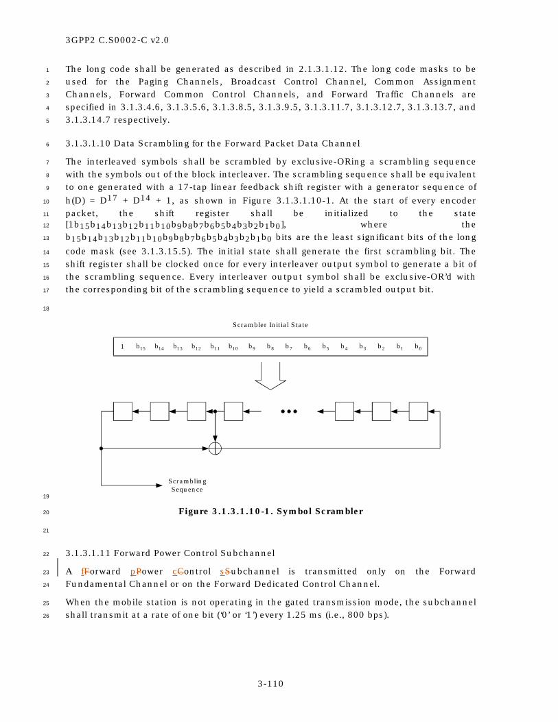
3GPP2 C.S0002-C v2.0
3-110
The long code shall be generated as described in 2.1.3.1.12. The long code masks to be 1
used for the Paging Channels, Broadcast Control Channel, Common Assignment 2
Channels, Forward Common Control Channels, and Forward Traffic Channels are 3
specified in 3.1.3.4.6, 3.1.3.5.6, 3.1.3.8.5, 3.1.3.9.5, 3.1.3.11.7, 3.1.3.12.7, 3.1.3.13.7, and 4
3.1.3.14.7 respectively. 5
3.1.3.1.10 Data Scrambling for the Forward Packet Data Channel 6
The interleaved symbols shall be scrambled by exclusive-ORing a scrambling sequence 7
with the symbols out of the block interleaver. The scrambling sequence shall be equivalent 8
to one generated with a 17-tap linear feedback shift register with a generator sequence of 9
h(D) = D17 + D14 + 1, as shown in Figure 3.1.3.1.10-1. At the start of every encoder 10
packet, the shift register shall be initialized to the state 11
[1b15b14b13b12b11b10b9b8b7b6b5b4b3b2b1b0], where the 12
b15b14b13b12b11b10b9b8b7b6b5b4b3b2b1b0 bits are the least significant bits of the long 13
code mask (see 3.1.3.15.5). The initial state shall generate the first scrambling bit. The 14
shift register shall be clocked once for every interleaver output symbol to generate a bit of 15
the scrambling sequence. Every interleaver output symbol shall be exclusive-OR’d with 16
the corresponding bit of the scrambling sequence to yield a scrambled output bit. 17
18
ScramblingSequence
Scrambler Initial State
1 0b7b 6b 5b 4b 3b 2b 1b8b15b 14b 13b 12b 11b 10b 9b
19
Figure 3.1.3.1.10-1. Symbol Scrambler 20
21
3.1.3.1.11 Forward Power Control Subchannel 22
A fForward pPower cControl sSubchannel is transmitted only on the Forward 23
Fundamental Channel or on the Forward Dedicated Control Channel. 24
When the mobile station is not operating in the gated transmission mode, the subchannel 25
shall transmit at a rate of one bit (‘0’ or ‘1’) every 1.25 ms (i.e., 800 bps). 26

3GPP2 C.S0002-C v2.0
3-111
When the mobile station is operating in the gated transmission mode, the subchannel 1
shall transmit at a rate of 400 or 200 bps when the gating rate is 1/2 or 1/4 respectively 2
as shown in Figure 3.1.3.1.11-1. 3
The power control groups within a 20 ms frame are numbered from 0 to 15. When 4
operating with 1/2 rate Reverse Pilot Channel gating, the fForward pPower cControl 5
sSubchannel shall be transmitted only in the even numbered power control groups. When 6
operating with 1/4 rate Reverse Pilot Channel gating, the fForward pPower cControl 7
sSubchannel shall be transmitted only in power control groups 1, 5, 9, and 13. 8
When using gating other than Reverse Pilot Channel gating with Reverse Radio 9
Configurations 3 through 6, the base station shall transmit the power control bit in the 10
power control group that begins (REV_PWR_CNTL_DELAY + 1) × 1.25 ms following the end 11
of a power control group in which the mobile station transmitted. 12
A ‘0’ bit shall indicate to the mobile station that it is to increase the mean output power 13
level, and a ‘1’ bit shall indicate to the mobile station that it is to decrease the mean 14
output power level. The amount that the mobile station increases or decreases its power 15
for every power control bit is specified in 2.1.2.3.2. 16
17

3GPP2 C.S0002-C v2.0
3-112
Gating Rate = 1
ForwardPower Control SubchannelTransmission at 800 bps
Reverse Pilot ChannelReception
1.25 msForward
Power Control SubchannelTransmission at 400 bps
Reverse Pilot ChannelReception
ForwardPower Control SubchannelTransmission at 200 bps
Reverse Pilot ChannelReception
power control subchannel transmission as specified in Table 3.1.3.1.11-1 and Figure 3.1.3.1.11-2
1.25 ms
1.25 ms
Gating Rate = 1/2
Gating Rate = 1/4
0 1 2 3 4 5 6 7 8 9 11 12 13 14 1510
0 1 2 3 4 5 6 7 8 9 11 12 13 14 1510
0 1 2 3 4 5 6 7 8 9 11 12 13 14 1510
20 ms = 16 Power Control Groups
20 ms = 16 Power Control Groups
20 ms = 16 Power Control Groups
Round TripDelay
Round TripDelay
Round TripDelay
0 1 2 3 4 5 6 7 8 9 11 12 13 14 1510
0 1 2 3 4 5 6 7 8 9 11 12 13 14 1510
0 1 2 3 4 5 6 7 8 9 11 12 13 14 1510
Power Control BitPilot
1
Figure 3.1.3.1.11-1. Forward and Reverse Power Control Subchannel Transmission 2
Timing 3
4
The base station receiver shall estimate the received signal strength of the particular 5
mobile station to which it is assigned over a 1.25 ms period. The base station receiver 6
shall use the estimate to determine the value of the power control bit (‘0’ or ‘1’). The base 7
station shall transmit the power control bit on the Forward Fundamental Channel or on 8
the Forward Dedicated Control Channel using the puncturing technique described below. 9
For Radio Configurations 1 and 2, the transmission of the power control bit shall occur in 10
the second power control group following the corresponding reverse channel power control 11
group in which the signal strength was estimated25. 12
In the case of non-gated transmission mode, the transmission of the power control bit 13
shall occur on the Forward Fundamental Channel or on the Forward Dedicated Control 14
25 For example, the signal is received on the Reverse Traffic Channel in power control group number
7, and the corresponding power control bit is transmitted on the Forward Traffic Channel during
power control group number 7 + 2 = 9.

3GPP2 C.S0002-C v2.0
3-113
Channel (as specified by FPC_PRI_CHANs) in all of the power control groups. In the case of 1
Reverse Pilot Channel gated transmission mode (at 1/2 or 1/4 rate), the transmission of 2
the power control bit shall occur on the Forward Dedicated Control Channel in every 3
second or fourth power control group as shown in Figure 3.1.3.1.11-1. 4
The duration and power level of power control bits for each radio configuration are 5
specified in Table 3.1.3.1.11-1. Each power control bit shall replace the number of 6
modulation symbols specified in Table 3.1.3.1.11-1. Each power control bit shall be 7
transmitted with minimum energy as specified in Table 3.1.3.1.11-1. The power control 8
bits shall be inserted into the Forward Dedicated Control Channel or into the Forward 9
Fundamental Channel data stream, after the data scrambling. 10
An n-bit (n = 3 or 4) binary number with values 0 through 2n –-- 1 formed by the 11
decimated bits specified in Table 3.1.3.1.11-1 shall be used to determine the power 12
control bit starting position by indexing the list in Table 3.1.3.1.11-1. For example, if the 13
values of decimated bits for Radio Configuration 4 (non-TD) are ‘110’ (6 decimal), the 14
power control bit starting position is 12 as shown in Figure 3.1.3.1.11-2. The value of the 15
decimated bits shall be equal to the first of the chips into the decimator (see Figure 16
3.1.3.1.1.1-20 and Figure 3.1.3.1.1.2-15) for each modulation symbol. 17
When operating with Radio Configurations 1 and 2, all unpunctured modulation symbols 18
in a frame are transmitted at the same power level. Modulation symbols in adjacent 19
frames may be sent at different power levels. 20
21

3GPP2 C.S0002-C v2.0
3-114
Table 3.1.3.1.11-1. Power Control Bit Duration and Power Level 1
Radio Configuration
Punctured Modulation
Symbols
Minimum Power Control Bit
Energy
Starting Symbol Positions
Decimated Bits (MSB →→→→ LSB)
1 2 Eb 0, 1,…, 15 23, 22, 21, 20
2 1 3Eb/4 0, 1,…, 15 23, 22, 21, 20
3 (non-TD) 4 Eb 0, 2,…, 30 47, 46, 45, 44
3 (TD) 4 Eb 0, 4,…, 28 47, 46, 45
4 (non-TD) 2 Eb 0, 2,…, 14 23, 22, 21
4 (TD) 2 Eb 0, 2,…, 14 23, 22, 21
5 (non-TD) 4 Eb 0, 2,…, 30 47, 46, 45, 44
5 (TD) 4 Eb 0, 4,…, 28 47, 46, 45
6 6 Eb 0, 6,…, 42 71, 70, 69
7 3 Eb 0, 3,…, 21 35, 34, 33
8 6 Eb 0, 6,…, 42 71, 70, 69
9 3 Eb 0, 3,…, 21 35, 34, 33
Notes:
Eb is the energy per bit of the Forward Fundamental Channel or Forward Dedicated
Control Channel (RC 3, 4, 5, 6, 7, 8, and 9) being punctured.
The decimated bits are numbered so that the first bit from the decimator in every power
control group is the zeroth, the next one is the first, etc.
2
0 1 2 3 4 5 6 7 8 9 10 11
LL 0 1 0 1 1 0 1
Decimated long code bits
1.25 ms = 1 Power Control Group
For RadioConfiguration 4
(non-TD), '110' = 6decimal = power
control bit startingposition 12
12 13
3
Figure 3.1.3.1.11-2. Randomization of Power Control Bit Starting Positions 4
5

3GPP2 C.S0002-C v2.0
3-115
3.1.3.1.12 Subpacket Symbol Selection for the Forward Packet Data Channel 1
Encoder packets are transmitted as one or more subpackets. Initially, the first subpacket 2
is transmitted. Then, subsequent subpackets are transmitted if requested by the mobile 3
station. See [3] for a more complete description of the control of the Forward Ppacket Data 4
Channel. The symbols in a subpacket are formed by selecting specific sequences of 5
symbols from the interleaved and scrambled turbo encoder output sequence. The 6
resulting subpacket sequence is a binary sequence of symbols for the modulator. 7
Let 8
k be the subpacket index; 9
NEP be the number of bits in the encoder packet (NEP = 408, 792, 1560, 2328, 3096, 10
or 3864); 11
NWalsh,k be the number of 32-chip Walsh channels for the k-th subpacket; 12
Nslots,k be the number of 1.25-ms slots for the k-th subpacket; 13
mk be the modulation order for the k-th subpacket (mk = 2 for QPSK, 3 for 8-PSK, 14
and 4 for 16-QAM); and 15
SPIDk be the subpacket ID for the k-th subpacket (SPIDk = 0, 1, 2, or 3). 16
Also, let the scrambled and selected symbols be numbered from zero with the 0-th symbol 17
being the first symbol in the sequence. Then, the index of the i-th symbol for the k-th 18
subpacket shall be 19
k,i k MAXS = (F +i)mod(P ) , 20
where i = 0 to Lk – 1, 21
k Walsh,k slots,k kL 48N N m= , 22
k k k MAXF = (SPID L )mod(P ) , and. 23
MAX EPP = min(7800, 5N ) . 24
The NEP, NWalsh,k, and Nslots,k values are determined by the base station and are 25
provided to the mobile station through the Forward Packet Data Control Channels. The 26
mk parameter is determined according to the rule specified in 3.1.3.1.13.4. 27
28
3.1.3.1.13 Modulation for the Forward Packet Data Channel 29
For a Forward Packet Data Channel operating with Radio Configuration 10, the symbols 30
from the subpacket symbol selection operation are mapped into a sequence of QPSK, 8-31
PSK, or 16-QAM modulation symbols. The type of modulation depends on the encoder 32
packet size, number of Walsh channels, and number of slots, as specified in 3.1.3.1.13.4. 33
3.1.3.1.13.1 QPSK Modulation 34
For subpackets that use QPSK modulation (modulation order = 2), groups of two 35
successive symbols out of the subpacket symbol selection operation shall be grouped to 36

3GPP2 C.S0002-C v2.0
3-116
form QPSK modulation symbols. Each group of two adjacent symbol-selection-operation 1
output symbols, s0 = x(2i) and s1 = x(2i + 1), i = 0,…, M – 1, shall be mapped into a 2
complex modulation symbol (mI(i), mQ(i)) as specified in Table 3.1.3.1.13.1-1. The 3
parameter M is the number of QPSK modulation symbols in all the Walsh channels of the 4
Forward Packet Data Channel subpacket. Figure 3.1.3.1.13.1-1 shows the signal 5
constellation of the QPSK modulator, where s0 = x(2i) and s1 = x(2i + 1). 6
7
Table 3.1.3.1.13.1-1. QPSK Modulation Table 8
Symbol-Selection-Operation Output Symbols Modulation Symbols
s1
x(2i + 1)
s0
x(2i) mI(ik) mQ(ik)
0 0 D D
0 1 –D D
1 0 D –D
1 1 –D –D
Note: D 1 2= .
9
Q Channel
I Channel
1 0s s
1 2−
0001
11 10
1 2
1 21 2−
10
Figure 3.1.3.1.13.1-1. Signal Constellation for QPSK Modulation 11
12
3.1.3.1.13.2 8-PSK Modulation 13
For subpackets that use 8-PSK modulation (modulation order = 3), the symbols out of the 14
subpacket symbol selection operation shall be grouped to form 8-PSK modulation 15
symbols: s0 = x(2M + i), s1 = x(2i), and s2 = x(2i + 1). These groups of three symbol-16
selection-operation output symbols shall be mapped into complex modulation symbols 17
(mI(i), mQ(i)), i = 0,…, M – 1,; k = 0, 1, 2; as specified in Table 3.1.3.1.13.2-1. The 18
parameter M is the number of 8-PSK modulation symbols in all the Walsh channels of the 19

3GPP2 C.S0002-C v2.0
3-117
Forward Packet Data Channel subpacket. Figure 3.1.3.1.13.2-1 shows the signal 1
constellation of the 8-PSK modulator, where s0 = x(2M + i), s1 = x(2i), and s2 = x(2i + 1). 2
3
Table 3.1.3.1.13.2-1. 8-PSK Modulation Table 4
Symbol-Selection-Operation Output Symbols Modulation Symbols
s2 s1 s0 mI(ik) mQ(ik)
0 0 0 C S
0 0 1 S C
0 1 1 –S C
0 1 0 –C S
1 1 0 –C –S
1 1 1 –S –C
1 0 1 S –C
1 0 0 C –S
Note: C cos( /8) 0.9239= π ≈ and S sin( /8) 0.3827= π ≈ .
5
Q Channel
I Channel
000
–C –S CS
–C
–S
C
S
2 1 0s s s
C = cos( /8)S = sin( /8)
ππ001011
010
100
111
110
101
6
Figure 3.1.3.1.13.2-1. Signal Constellation for 8-PSK Modulation 7
8
3.1.3.1.13.3 16-QAM Modulation 9
For subpackets that use 16-QAM modulation (modulation order = 4), the symbols out of 10
the subpacket symbol selection operation shall be grouped to form 16-QAM modulation 11
symbols: s0 = x(2M + 2i), s1 = x(2i), s2 = x(2M + 2i + 1), and s3 = x(2i + 1). These groups of 12
four symbol-selection-operation output symbols shall be mapped into complex modulation 13
symbols (mI(i), mQ(i)), i = 0,…, M – 1,; k = 0, 1, 2, 3; as specified in Table 3.1.3.1.13.3-1. 14

3GPP2 C.S0002-C v2.0
3-118
The parameter M is the number of 16-QAM modulation symbols in all the Walsh channels 1
of the Forward Packet Data Channel subpacket. Figure 3.1.3.1.13.3-1 shows the signal 2
constellation of the 16-QAM modulator, where s0 = x(2M + 2i), s1 = x(2i), s2 = x(2M + 2i + 3
1), and s3 = x(2i + 1). 4
5
Table 3.1.3.1.13.3-1. 16-QAM Modulation Table 6
Symbol-Selection-Operation Output Symbols Modulation Symbols
s3 s2 s1 s0 mI(ik) mQ(ik)
0 0 0 0 3A 3A
0 0 0 1 A 3A
0 0 1 1 –A 3A
0 0 1 0 –3A 3A
0 1 0 0 3A A
0 1 0 1 A A
0 1 1 1 –A A
0 1 1 0 –3A A
1 1 0 0 3A –A
1 1 0 1 A –A
1 1 1 1 –A –A
1 1 1 0 –3A –A
1 0 0 0 3A –3A
1 0 0 1 A –3A
1 0 1 1 –A –3A
1 0 1 0 –3A –3A
Note: A 1 10 0.3162= ≈ .
7

3GPP2 C.S0002-C v2.0
3-119
Q Channel
I Channel
00000011
1000
0001
0110
0010
010001010111
1100110111111110
100110111010
–3A –A 3AA
–3A
–A
3A
A
3 2 1 0s s s s
A = 1 10
1
Figure 3.1.3.1.13.3-1. Signal Constellation for 16-QAM Modulation 2
3
3.1.3.1.13.4 Modulation Order 4
The base station shall set the modulation order for all the allowed subpacket formats that 5
can be transmitted by the base station as shown in Table 3.1.3.1.13.4-1.26 The subpacket 6
modulation symbols are the QPSK, 8-PSK, or 16-QAM symbols. The subpacket data rate is 7
the number of encoder packet bits divided by the subpacket duration. The effective 8
subpacket code rate is defined as the number of bits in the encoder packet divided by the 9
number of subpacket binary code symbols in all of the slots and Walsh channels of the 10
Forward Packet Data Channel subpacket. In the notation of 3.1.3.1.12, the effective 11
subpacket code rate of the k-th subpacket of an encoder packet is equal to NEP/Lk. 12
26In the notation of 3.1.3.1.12, define the Modulation order Product code Rate of the k-th subpacket of an encoder packet as
= EPk
Walsh,k slots,k
NMPR
48N N.
Then, the modulation order is specified by the following rule:
• If 0 < MPRk ≤ 3/2, then a modulation order of 2 (i.e., QPSK) is used.
• If 3/2 < MPRk ≤ 2, then a modulation order of 3 (i.e., 8-PSK) is used.
• If 2 < MPRk ≤ 3.2, then a modulation order of 4 (i.e., 16-QAM) is used.

3GPP2 C.S0002-C v2.0
3-120
Table 3.1.3.1.13.4-1. Forward Packet Data Channel Parameters with Radio 1
Configuration 10 2
Number of Bits per Encoder Packet
Number of 32-Chip Walsh
Channels
Subpacket Data Rate
(kbps)
Number of Slots per
Subpacket
Modulation Order
Effective Subpacket
Code Rate
Number of Subpacket Modulation
Symbols per Walsh Channel
Number of Subpacket
Binary Code
Symbols
2,328 28 1,862.4 1 3 0.5774 48 4,032
3,864 27 1,545.6 2 2 0.7454 96 5,184
3,096 26 2,476.8 1 4 0.6202 48 4,992
3,864 26 3,091.2 1 4 0.7740 48 4,992
1,560 25 1,248.0 1 2 0.6500 48 2,400
2,328 25 1,862.4 1 3 0.6467 48 3,600
3,096 25 1,238.4 2 2 0.6450 96 4,800
3,864 25 1,545.6 2 3 0.5367 96 7,200
2,328 23 931.2 2 2 0.5272 96 4,416
2,328 23 1,862.4 1 4 0.5272 48 4,416
3,096 23 2,476.8 1 4 0.7011 48 4,416
3,864 23 1,545.6 2 3 0.5833 96 6,624
1,560 22 1,248.0 1 2 0.7386 48 2,112
3,096 22 1,238.4 2 2 0.7330 96 4,224
1,560 21 1,248.0 1 3 0.5159 48 3,024
3,096 21 1,238.4 2 3 0.5119 96 6,048
3,096 21 2,476.8 1 4 0.7679 48 4,032
3,864 21 1,545.6 2 3 0.6389 96 6,048
1,560 20 624.0 2 2 0.4063 96 3,840
2,328 20 465.6 4 2 0.3031 192 7,680
2,328 20 931.2 2 2 0.6063 96 3,840
2,328 20 1,862.4 1 4 0.6063 48 3,840
3,096 20 619.2 4 2 0.4031 192 7,680
408 19 326.4 1 2 0.2237 48 1,824
792 19 316.8 2 2 0.2171 96 3,648
792 19 633.6 1 2 0.4342 48 1,824
1,560 19 1,248.0 1 3 0.5702 48 2,736

3GPP2 C.S0002-C v2.0
3-121
Number of Bits per Encoder Packet
Number of 32-Chip Walsh
Channels
Subpacket Data Rate
(kbps)
Number of Slots per
Subpacket
Modulation Order
Effective Subpacket
Code Rate
Number of Subpacket Modulation
Symbols per Walsh Channel
Number of Subpacket
Binary Code
Symbols
3,096 19 1,238.4 2 3 0.5658 96 5,472
3,864 19 772.8 4 2 0.5296 192 7,296
3,864 19 1,545.6 2 4 0.5296 96 7,296
2,328 18 1,862.4 1 4 0.6736 48 3,456
1,560 17 1,248.0 1 3 0.6373 48 2,448
2,328 17 931.2 2 2 0.7132 96 3,264
3,096 17 1,238.4 2 3 0.6324 96 4,896
3,864 17 1,545.6 2 4 0.5919 96 6,528
2,328 16 1,862.4 1 4 0.7578 48 3,072
3,096 16 619.2 4 2 0.5039 192 6,144
3,864 16 772.8 4 2 0.6289 192 6,144
792 15 633.6 1 2 0.5500 48 1,440
1,560 15 624.0 2 2 0.5417 96 2,880
1,560 15 1,248.0 1 4 0.5417 48 2,880
2,328 15 931.2 2 3 0.5389 96 4,320
3,096 15 1,238.4 2 4 0.5375 96 5,760
3,864 15 1,545.6 2 4 0.6708 96 5,760
1,560 14 312.0 4 2 0.2902 192 5,376
2,328 14 465.6 4 2 0.4330 192 5,376
3,864 14 772.8 4 2 0.7188 192 5,376
3,864 14 1,545.6 2 4 0.7188 96 5,376
792 13 633.6 1 2 0.6346 48 1,248
1,560 13 624.0 2 2 0.6250 96 2,496
1,560 13 1,248.0 1 4 0.6250 48 2,496
2,328 13 931.2 2 3 0.6218 96 3,744
3,096 13 619.2 4 2 0.6202 192 4,992
3,096 13 1,238.4 2 4 0.6202 96 4,992
3,864 13 1,545.6 2 4 0.7740 96 4,992
1,560 12 1,248.0 1 4 0.6771 48 2,304

3GPP2 C.S0002-C v2.0
3-122
Number of Bits per Encoder Packet
Number of 32-Chip Walsh
Channels
Subpacket Data Rate
(kbps)
Number of Slots per
Subpacket
Modulation Order
Effective Subpacket
Code Rate
Number of Subpacket Modulation
Symbols per Walsh Channel
Number of Subpacket
Binary Code
Symbols
3,096 12 1,238.4 2 4 0.6719 96 4,608
3,864 12 772.8 4 3 0.5590 192 6,912
408 11 326.4 1 2 0.3864 48 1,056
792 11 158.4 4 2 0.1875 192 4,224
792 11 316.8 2 2 0.3750 96 2,112
792 11 633.6 1 2 0.7500 48 1,056
1,560 11 624.0 2 2 0.7386 96 2,112
1,560 11 1,248.0 1 4 0.7386 48 2,112
2,328 11 465.6 4 2 0.5511 192 4,224
2,328 11 931.2 2 4 0.5511 96 4,224
3,096 11 619.2 4 2 0.7330 192 4,224
3,096 11 1,238.4 2 4 0.7330 96 4,224
3,864 11 772.8 4 3 0.6098 192 6,336
792 10 633.6 1 3 0.5500 48 1,440
1,560 10 624.0 2 3 0.5417 96 2,880
2,328 10 931.2 2 4 0.6063 96 3,840
3,096 10 619.2 4 3 0.5375 192 5,760
792 9 633.6 1 3 0.6111 48 1,296
1,560 9 312.0 4 2 0.4514 192 3,456
1,560 9 624.0 2 3 0.6019 96 2,592
2,328 9 465.6 4 2 0.6736 192 3,456
2,328 9 931.2 2 4 0.6736 96 3,456
3,096 9 619.2 4 3 0.5972 192 5,184
3,864 9 772.8 4 4 0.5590 192 6,912
408 8 163.2 2 2 0.2656 96 1,536
408 8 326.4 1 2 0.5313 48 768
792 8 316.8 2 2 0.5156 96 1,536
792 8 633.6 1 4 0.5156 48 1,536
1,560 8 624.0 2 4 0.5078 96 3,072

3GPP2 C.S0002-C v2.0
3-123
Number of Bits per Encoder Packet
Number of 32-Chip Walsh
Channels
Subpacket Data Rate
(kbps)
Number of Slots per
Subpacket
Modulation Order
Effective Subpacket
Code Rate
Number of Subpacket Modulation
Symbols per Walsh Channel
Number of Subpacket
Binary Code
Symbols
2,328 8 465.6 4 3 0.5052 192 4,608
2,328 8 931.2 2 4 0.7578 96 3,072
3,096 8 619.2 4 4 0.5039 192 6,144
3,864 8 772.8 4 4 0.6289 192 6,144
408 7 326.4 1 2 0.6071 48 672
792 7 316.8 2 2 0.5893 96 1,344
792 7 633.6 1 4 0.5893 48 1,344
1,560 7 312.0 4 2 0.5804 192 2,688
1,560 7 624.0 2 4 0.5804 96 2,688
2,328 7 465.6 4 3 0.5774 192 4,032
3,096 7 619.2 4 4 0.5759 192 5,376
3,864 7 772.8 4 4 0.7188 192 5,376
408 6 326.4 1 2 0.7083 48 576
792 6 158.4 4 2 0.3438 192 2,304
792 6 316.8 2 2 0.6875 96 1,152
792 6 633.6 1 4 0.6875 48 1,152
1,560 6 312.0 4 2 0.6771 192 2,304
1,560 6 624.0 2 4 0.6771 96 2,304
2,328 6 465.6 4 4 0.5052 192 4,608
3,096 6 619.2 4 4 0.6719 192 4,608
408 5 163.2 2 2 0.4250 96 960
408 5 326.4 1 3 0.5667 48 720
792 5 316.8 2 3 0.5500 96 1,440
1,560 5 312.0 4 3 0.5417 192 2,880
2,328 5 465.6 4 4 0.6063 192 3,840
408 4 81.6 4 2 0.2656 192 1,536
408 4 163.2 2 2 0.5313 96 768
408 4 326.4 1 4 0.5313 48 768
792 4 158.4 4 2 0.5156 192 1,536
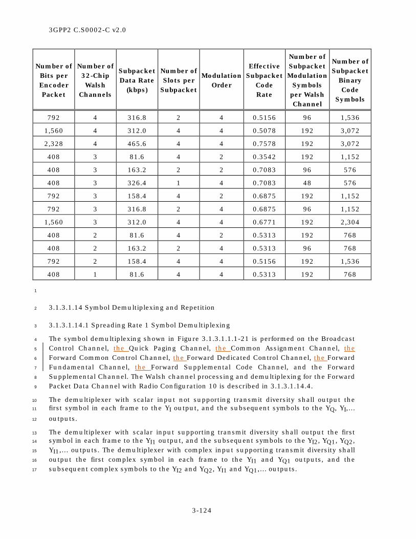
3GPP2 C.S0002-C v2.0
3-124
Number of Bits per Encoder Packet
Number of 32-Chip Walsh
Channels
Subpacket Data Rate
(kbps)
Number of Slots per
Subpacket
Modulation Order
Effective Subpacket
Code Rate
Number of Subpacket Modulation
Symbols per Walsh Channel
Number of Subpacket
Binary Code
Symbols
792 4 316.8 2 4 0.5156 96 1,536
1,560 4 312.0 4 4 0.5078 192 3,072
2,328 4 465.6 4 4 0.7578 192 3,072
408 3 81.6 4 2 0.3542 192 1,152
408 3 163.2 2 2 0.7083 96 576
408 3 326.4 1 4 0.7083 48 576
792 3 158.4 4 2 0.6875 192 1,152
792 3 316.8 2 4 0.6875 96 1,152
1,560 3 312.0 4 4 0.6771 192 2,304
408 2 81.6 4 2 0.5313 192 768
408 2 163.2 2 4 0.5313 96 768
792 2 158.4 4 4 0.5156 192 1,536
408 1 81.6 4 4 0.5313 192 768
1
3.1.3.1.14 Symbol Demultiplexing and Repetition 2
3.1.3.1.14.1 Spreading Rate 1 Symbol Demultiplexing 3
The symbol demultiplexing shown in Figure 3.1.3.1.1.1-21 is performed on the Broadcast 4
Control Channel, the Quick Paging Channel, the Common Assignment Channel, the 5
Forward Common Control Channel, the Forward Dedicated Control Channel, the Forward 6
Fundamental Channel, the Forward Supplemental Code Channel, and the Forward 7
Supplemental Channel. The Walsh channel processing and demultiplexing for the Forward 8
Packet Data Channel with Radio Configuration 10 is described in 3.1.3.1.14.4. 9
The demultiplexer with scalar input not supporting transmit diversity shall output the 10
first symbol in each frame to the YI output, and the subsequent symbols to the YQ, YI,… 11
outputs. 12
The demultiplexer with scalar input supporting transmit diversity shall output the first 13
symbol in each frame to the YI1 output, and the subsequent symbols to the YI2, YQ1, YQ2, 14
YI1,… outputs. The demultiplexer with complex input supporting transmit diversity shall 15
output the first complex symbol in each frame to the YI1 and YQ1 outputs, and the 16
subsequent complex symbols to the YI2 and YQ2, YI1 and YQ1,… outputs. 17

3GPP2 C.S0002-C v2.0
3-125
The Forward Pilot Channel, the Transmit Diversity Pilot Channel, the Auxiliary Pilot 1
Channels, and the Auxiliary Transmit Diversity Pilot Channels shall be demultiplexed 2
using the non-TD demultiplexer (i.e., the TD demultiplexer is not allowed). 3
The Sync Channel, Paging Channels, the Forward Packet Data Control Channel, and the 4
Forward Traffic Channels with Radio Configurations 1 and 2 shall be demultiplexed using 5
the non-TD demultiplexer only (i.e., the TD demultiplexer is not allowed). 6
The Broadcast Control Channels, the Common Power Control Channels, the Common 7
Assignment Channels, the Forward Common Control Channels, and Forward Traffic 8
Channels with Radio Configurations 3 through 5 shall be demultiplexed using either the 9
non-TD or TD demultiplexer. 10
The Quick Paging Channel, when used in conjunction with the Paging Channel, shall be 11
demultiplexed using the non-TD demultiplexer (see Figure 3.1.3.1.1.1-21). Otherwise, the 12
Quick Paging Channel may be demultiplexed using the non-TD or TD demultiplexer. 13
3.1.3.1.14.2 Spreading Rate 1 Symbol Repetition for Transmit Diversity 14
If OTD mode is enabled, each symbol output on YI1, YI2, YQ1, and YQ2 shall be repeated 15
once, to create two output symbols for each input symbol to the symbol repeater. The first 16
repeated symbol output from both the YI2 and YQ2 symbol repetition blocks during a 17
frame shall not be inverted. Subsequent outputs from both the YI2 and YQ2 symbol 18
repetition blocks shall be alternatively inverted. 19
If STS mode is enabled, each symbol output on YI1, YI2, YQ1, and YQ2 shall be applied to 20
two repeaters, one for each transmit antenna, as shown in Figure 3.1.3.1.1.1-24 to create 21
two output symbols for each symbol input to the symbol repeater. On antenna 1 the first 22
repeated output symbol from the YI2 repetition block shall be inverted and the second 23
repeated output symbol shall not be inverted. Subsequent output symbols from the YI2 24
repetition block on antenna 1 shall be alternatively inverted. The first repeated output 25
symbol from the YQ2 symbol repetition block on antenna 1 shall not be inverted and the 26
second repeated output symbol shall be inverted. Subsequent output symbols from the 27
YQ2 symbol repetition block shall be alternatively inverted. On antenna 2 the first 28
repeated output symbol from the YQ1 repetition block shall be inverted and the second 29
repeated output symbol shall not be inverted. Subsequent output symbols from YQ1 30
repetition block on antenna 2 shall be alternatively inverted. The first repeated output 31
symbol from the YI1 symbol repetition block on antenna 2 shall not be inverted and the 32
second repeated output symbol shall be inverted. Subsequent output symbols from the 33
YI1 symbol repetition block shall be alternatively inverted. 34
3.1.3.1.14.3 Spreading Rate 3 Symbol Demultiplexing 35
Symbol demultiplexing is performed on every code channel in the Forward CDMA Channel 36
as shown in Figure 3.1.3.1.1.2-16. 37
The demultiplexer shall output the first symbol in each frame to the YI1 output and the 38
subsequent symbols to the YI2, YI3, YQ1, YQ2, YQ3, YI1,… outputs. The demultiplexer 39
shall output the first complex symbol in each frame to the YI1 and YQ1 outputs, and the 40
subsequent complex symbols to the YI2 and YQ2, YI3 and YQ3, YI1 and YQ1,… outputs. 41

3GPP2 C.S0002-C v2.0
3-126
The Forward Pilot Channel and the Auxiliary Pilot Channels, shall be demultiplexed using 1
the demultiplexer shown in Figure 3.1.3.1.1.2-16. 2
The Broadcast Control Channels, the Common Power Control Channels, the Common 3
Assignment Channels, the Forward Common Control Channels, the Quick Paging 4
Channels, and Forward Traffic Channels with Radio Configurations 6 through 9 shall be 5
demultiplexed using the demultiplexer shown in Figure 3.1.3.1.1.2-16. 6
3.1.3.1.14.4 Symbol Demultiplexing and Walsh Channel Processing for the Forward 7
Packet Data Channel 8
When using the Forward Packet Data Channel, the in-phase stream at the output of 9
QPSK/8-PSK/16-QAM modulator shall be demultiplexed into N parallel streams labeled I1, 10
I2,..., IN, where N is the total number of 32-chip Walsh codes that are indicated in 11
WCI_SET.WCI_SET is a parameter that the Physical layer received from the MAC Layer in 12
PHY-FPDCH.Request or PHY-DecodeFPDCH.Request. WCI_SET is a vector of N elements 13
with each element specifying a 32-chip Walsh code index WWCI_SET[n]32 (0 ≤ n ≤ N-1), that 14
is used for the Forward Packet Data Channel. If mI(1), mI(2), mI(3),... denotes the sequence 15
of the modulation output in the in-phase stream, then for each k = 1, 2,..., N, the kth 16
demultiplexed stream Ik shall consist of the values mI(k), mI(N + k), mI(2N + k), mI(3N + 17
k),…. 18
Similarly, the quadrature stream at the output of the QPSK/8-PSK/16-QAM modulator 19
shall be demultiplexed into N parallel streams labeled Q1, Q2,..., QN. If mQ(1), mQ(2), 20
mQ(3),… denotes the sequence of the modulation output values in the quadrature stream, 21
then for each k = 1, 2,..., N, the kth demultiplexed stream Qk shall consist of the values 22
mQ(k), mQ(N + k), mQ(2N + k), mQ(3N + k),…. 23
For each k = 1, 2,..., N, the demultiplexed streams with labels Ik and Qk shall be assigned 24
to the in-phase and quadrature phases, respectively, of the kth Walsh code that appears in 25
the WCI_SET. 26
27
Following the Walsh channel spreading, the spread subpacket modulation symbols from 28
the Walsh channels shall be summed to form a single sequence of (I, Q) symbols. 29
3.1.3.1.15 Orthogonal and Quasi-Orthogonal Spreading 30
Walsh functions are used with Radio Configurations 1, 2, and 10. Walsh functions or 31
quasi-orthogonal functions are used with Radio Configurations 3 through 9. 32
Each code channel transmitted on the Forward CDMA Channel shall be spread with a 33
Walsh function or a quasi-orthogonal function at a fixed chip rate of 1.2288 Mcps to 34
provide channelization among all code channels on a given Forward CDMA Channel. 35
The maximum length of the assigned Walsh functions (Nmax) for code channels, except for 36
the Auxiliary Pilot Channels and the Auxiliary Transmit Diversity Pilot Channels, 37
transmitted on the Forward CDMA Channel is given in Table 3.1.3.1.15-1. One of N-ary (N 38
≤ Nmax) time-orthogonal Walsh functions, generated as described in 2.1.3.1.8.2, shall be 39
used. A code channel that is spread using Walsh function n from the N-ary orthogonal set 40

3GPP2 C.S0002-C v2.0
3-127
(0 ≤ n ≤ N – 1) shall be assigned to code channel WnN. Walsh function time alignment shall 1
be such that the first Walsh chip begins at an even second time mark referenced to base 2
station transmission time (see 3.1.5). The Walsh function spreading sequence shall repeat 3
with a period of (N/1.2288) µs. 4
5
Table 3.1.3.1.15-1. Maximum Walsh Function Length for Code Channels on the 6
Forward CDMA Channel Except the Auxiliary Pilot Channel and 7
Auxiliary Transmit Diversity Pilot Channel 8
Spreading Rate
Maximum Walsh Length
1 128
3 256
9
Quasi-orthogonal functions (QOFs) shall be created using a non-zero sign multiplier QOF 10
mask and a non-zero rotate enable Walsh function as specified in Table 3.1.3.1.15-2. The 11
repeated sequence of an appropriate Walsh function shall be multiplied by the repeated 12
sequence of masks with symbols +1 and –1, which correspond to the sign multiplier QOF 13
mask values of 0 and 1, respectively. The sequence shall also be multiplied by the 14
repeated sequence of masks with symbols 1 and j (j is the complex number representing a 15
90° phase shift) which correspond to the rotate enable Walsh function values of 0 and 1, 16
respectively. The sign multiplier QOF masks (QOFsign) and the rotate enable Walsh 17
functions (Walshrot) given in Table 3.1.3.13.2-2 shall be used. The mask sequence order 18
shall be output by rows from left to right for each row from top to bottom. Each hex 19
symbol is output from the most-significant bit to the least-significant bit. The time 20
alignment of QOFsign and Walshrot shall be such that the first Walsh chip of the quasi-21
orthogonal function begins at an even second time mark referenced to base station 22
transmission time (see 3.1.5). 23
24

3GPP2 C.S0002-C v2.0
3-128
Table 3.1.3.1.15-2. Masking Functions for Quasi-Orthogonal Functions with Length 1
256 2
Masking Function Function
Hexadecimal Representation of QOFsign Walshrot
0 00000000000000000000000000000000 00000000000000000000000000000000
W0256
1 7228d7724eebebb1eb4eb1ebd78d8d28 278282d81b41be1b411b1bbe7dd8277d
W130256
2 114b1e4444e14beeee4be144bbe1b4ee
dd872d77882d78dd2287d277772d87dd W173
256
3 1724bd71b28118d48ebddb172b187eb2 e7d4b27ebd8ee82481b22be7dbe871bd
W47256
3
The assignment of code channels shall be such that each code channel is orthogonal or 4
quasi-orthogonal to all other code channels in use. 5
Code channel W064 shall be assigned to the Forward Pilot Channel. Code channel W0
64 6
shall not be used with a non-zero quasi-orthogonal function. Non-zero quasi-orthogonal 7
functions shall not be used for the Forward Transmit Diversity Pilot Channel, the Auxiliary 8
Pilot Channel, the Auxiliary Transmit Diversity Pilot Channel, the Broadcast Control 9
Channel, the Quick Paging Channel, the Common Power Control Channel, the Common 10
Assignment Channel, the Forward Common Control Channel, the Forward Packet Data 11
Control Channel, and the Forward Packet Data Channel. Code channels W64kN, with and 12
without a non-zero quasi-orthogonal function, where N > 64 and k is an integer such that 13
0 ≤ 64k < N, shall not be used. 14
If the Transmit Diversity Pilot Channel is present, it shall be assigned code channel 15
W16128. 16
If an Auxiliary Pilot Channel is present, it shall be assigned a code channel WnN, where N 17
≤ 512, and 1 ≤ n ≤ N – 1. The value of N and n are specified by the base station. 18
If an Auxiliary Pilot Channel is used with an Auxiliary Transmit Diversity Pilot Channel, 19
then the Auxiliary Pilot Channel shall be assigned a code channel WnN, and the Auxiliary 20
Transmit Diversity Pilot Channel shall be assigned a code channel Wn+N/2N, where N ≤ 21
512 and 1 ≤ n ≤ N/2 – 1. The value of N and n are specified by the base station. 22
If the Sync Channel is present, it shall be assigned code channel W3264. 23
If Paging Channels are present, they shall be assigned to code channels W164 to W7
64, 24
consecutively. 25
3GPP2 C.S0002-C v2.0
3-129
If a Spreading Rate 1, rate 1/2 coded Broadcast Control Channel is present, it shall be 1
assigned to a code channel Wn64, where 1 ≤ n ≤ 63. See Figure 3.1.3.1.1.1-22, Figure 2
3.1.3.1.1.1-23, and Figure 3.1.3.1.1.1-24. The value of n is specified by the base station. 3
If a Spreading Rate 1, rate 1/4 coded Broadcast Control Channel is present, it shall be 4
assigned to a code channel Wn32, where 1 ≤ n ≤ 31. See Figure 3.1.3.1.1.1-22, Figure 5
3.1.3.1.1.1-23, and Figure 3.1.3.1.1.1-24. The value of n is specified by the base station. 6
If a Spreading Rate 3 Broadcast Control Channel is present, it shall be assigned to a code 7
channel Wn128, where 1 ≤ n ≤ 127. See Figure 3.1.3.1.1.2-17. The value of n is specified 8
by the base station. 9
If Spreading Rate 1 Quick Paging Channels are present, they shall be assigned to code 10
channels W80128, W48
128, and W112128, in that order. See Figure 3.1.3.1.1.1-22, Figure 11
3.1.3.1.1.1-23, and Figure 3.1.3.1.1.1-24. 12
If a Spreading Rate 3 Quick Paging channel is present, it shall be assigned to a code 13
channel Wn256, where 1 ≤ n ≤ 255. See Figure 3.1.3.1.1.2-17. The value of n is specified 14
by the base station. 15
If a Spreading Rate 1 Common Power Control Channel operating in the non-TD mode is 16
present, it shall be assigned to a code channel Wn128, where 1 ≤ n ≤ 127. See Figure 17
3.1.3.1.1.1-22. The value of n is specified by the base station. 18
If a Spreading Rate 1 Common Power Control Channel operating in the OTD or STS mode 19
is present, it shall be assigned to a code channel Wn64, where 1 ≤ n ≤ 63. See Figure 20
3.1.3.1.1.1-23 and Figure 3.1.3.1.1.1-24. The value of n is specified by the base station. 21
If a Spreading Rate 3 Common Power Control Channel is present, it shall be assigned to a 22
code channel Wn128, where 1 ≤ n ≤ 127. See Figure 3.1.3.1.1.2-17. The value of n is 23
specified by the base station. 24
If a Spreading Rate 1, rate 1/2 coded Common Assignment Channel is present, it shall be 25
assigned to a code channel Wn128, where 1 ≤ n ≤ 127. See Figure 3.1.3.1.1.1-22, Figure 26
3.1.3.1.1.1-23, and Figure 3.1.3.1.1.1-24. The value of n is specified by the base station. 27
If a Spreading Rate 1, rate 1/4 coded Common Assignment Channel is present, it shall be 28
assigned to a code channel Wn64, where 1 ≤ n ≤ 63. See Figure 3.1.3.1.1.1-22, Figure 29
3.1.3.1.1.1-23, and Figure 3.1.3.1.1.1-24. The value of n is specified by the base station. 30
If a Spreading Rate 3 Common Assignment Channel is present, it shall be assigned to a 31
code channel Wn256, where 1 ≤ n ≤ 255. See Figure 3.1.3.1.1.2-17. The value of n is 32
specified by the base station. 33
If a Spreading Rate 1, rate 1/2 coded Forward Common Control Channel is present, it 34
shall be assigned to a code channel WnN, where N = 32, 64, and 128 for the data rate of 35
38400 bps, 19200 bps, and 9600 bps, respectively, and 1 ≤ n ≤ N – 1. See Figure 36
3.1.3.1.1.1-22, Figure 3.1.3.1.1.1-23, and Figure 3.1.3.1.1.1-24. The value of n is specified 37
by the base station. 38

3GPP2 C.S0002-C v2.0
3-130
If a Spreading Rate 1, rate 1/4 coded Forward Common Control Channel is present, it 1
shall be assigned to a code channel WnN, where N = 16, 32, and 64 for the data rate of 2
38400 bps, 19200 bps, and 9600 bps, respectively, and 1 ≤ n ≤ N – 1. See Figure 3
3.1.3.1.1.1-22, Figure 3.1.3.1.1.1-23, and Figure 3.1.3.1.1.1-24. The value of n is specified 4
by the base station. 5
If a Spreading Rate 3 Forward Common Control Channel is present, it shall be assigned to 6
a code channel WnN, where N = 64, 128, and 256 for the data rate of 38400 bps, 19200 7
bps, and 9600 bps, respectively, and 1 ≤ n ≤ N – 1. See Figure 3.1.3.1.1.2-17. The value of 8
n is specified by the base station. 9
If a Forward Packet Data Control Channel is present, it shall be assigned to a code 10
channel Wn64, where 1 ≤ n ≤ 63 (see Figure 3.1.3.1.1.1-22). The value of n is specified by 11
the base station. 12
Each Forward Fundamental Channel and Forward Supplemental Code Channel with 13
Radio Configuration 1 or 2 shall be assigned to a code channel Wn64, where 1 ≤ n ≤ 63. 14
See Figure 3.1.3.1.1.1-22. The value of n is specified by the base station. 15
Each Forward Fundamental Channel and Forward Dedicated Control Channel with Radio 16
Configuration 3 or 5 shall be assigned to a code channel Wn64, where 1 ≤ n ≤ 63. See 17
Figure 3.1.3.1.1.1-22, Figure 3.1.3.1.1.1-23, and Figure 3.1.3.1.1.1-24. The value of n is 18
specified by the base station. 19
Each Forward Fundamental Channel and Forward Dedicated Control Channel with Radio 20
Configuration 4 shall be assigned to a code channel Wn128, where 1 ≤ n ≤ 127. See Figure 21
3.1.3.1.1.1-22, Figure 3.1.3.1.1.1-23, and Figure 3.1.3.1.1.1-24. The value of n is specified 22
by the base station. 23
Each Forward Fundamental Channel and Forward Dedicated Control Channel with Radio 24
Configuration 6 or 8 shall be assigned to a code channel Wn128, where 1 ≤ n ≤ 127. See 25
Figure 3.1.3.1.1.2-17. The value of n is specified by the base station. 26
Each Forward Fundamental Channel and Forward Dedicated Control Channel with Radio 27
Configuration 7 or 9 shall be assigned to a code channel Wn256, where 1 ≤ n ≤ 255. See 28
Figure 3.1.3.1.1.2-17. The value of n is specified by the base station. 29
Each Forward Supplemental Channel with Radio Configuration 3, 4, or 5 shall be assigned 30
to a code channel WnN, where N = 4, 8, 16, 32, 64, 128, 128, and 128 for the maximum 31
assigned QPSK symbol rate of 307200 sps, 153600 sps, 76800 sps, 38400 sps, 19200 sps, 32
9600 sps, 4800 sps, and 2400 sps, respectively, and 1 ≤ n ≤ N – 1. See Figure 3.1.3.1.1.1-33
22, Figure 3.1.3.1.1.1-23, and Figure 3.1.3.1.1.1-24. The value of n is explicitly specified 34
by the base station, while the value of N is indirectly specified by the base station by 35
explicitly specifying the radio configuration, the number of bits in the frame, and the 36
frame duration. For QPSK symbol rates of 4800 sps and 2400 sps, the Walsh function is 37
transmitted two times and four times per QPSK symbol, respectively. The effective length 38
of the Walsh function is 256 for the QPSK symbol rate of 4800 sps, and 512 for the QPSK 39
symbol rate of 2400 sps. 40

3GPP2 C.S0002-C v2.0
3-131
Each Forward Supplemental Channel with Radio Configuration 6, 7, 8, or 9 shall be 1
assigned to a code channel WnN, where N = 4, 8, 16, 32, 64, 128, 256, 256, and 256 for 2
the maximum assigned QPSK symbol rate of 921600 sps, 460800 sps, 230400 sps, 3
115200 sps, 57600 sps, 28800 sps, 14400 sps, 7200 sps, and 3600 sps, respectively, and 4
1 ≤ n ≤ N – 1. See Figure 3.1.3.1.1.2-17. The value of n is explicitly specified by the base 5
station, while the value of N is indirectly specified by the base station by explicitly 6
specifying the radio configuration, the number of bits in the frame, and the frame 7
duration. For QPSK symbol rates of 7200 sps and 3600 sps, the Walsh function is 8
transmitted two times and four times per QPSK symbol, respectively. The effective length 9
of the Walsh function is 512 for the QPSK symbol rate of 7200 sps, and 1024 for the QPSK 10
symbol rate of 3600 sps. 11
If a Forward Packet Data Channel with Radio Configuration 10 is present, it shall be 12
assigned to one to 28 code channels Wn32, where 1 ≤ n ≤ 31 (see Figure 3.1.3.1.1.1-19), 13
depending on the number of Walsh Channels in WCI_SET (see 3.1.3.1.14.4). The value of 14
n is specified by the base station. For specific data rates and modulations, refer to Table 15
3.1.3.1.13.4-1. 16
3.1.3.1.16 Quadrature Spreading 17
Following the orthogonal spreading, each code channel is spread in quadrature as shown 18
in Figure 3.1.3.1.1.1-10, Figure 3.1.3.1.1.1-19, Figure 3.1.3.1.1.1-22, Figure 3.1.3.1.1.1-19
23, Figure 3.1.3.1.1.1-24, and Figure 3.1.3.1.1.2-17. The spreading sequence shall be a 20
quadrature sequence of length 215 (i.e., 32768 PN chips in length) for Spreading Rate 1 21
and each carrier of Spreading Rate 3. This sequence is called the pilot PN sequence. 22
For Spreading Rate 1 and each carrier of Spreading Rate 3, the pilot PN sequence shall be 23
based on the following characteristic polynomials: 24
PI(x) = x15 + x13 + x9 + x8 + x7 + x5 + 1 25
(for the in-phase (I) sequence) 26
and 27
PQ(x) = x15 + x12 + x11+ x10 + x6 + x5 + x4 + x3 + 1 28
(for the quadrature-phase (Q) sequence). 29
The maximum length linear feedback shift register sequences i(n) and q(n) based on the 30
above polynomials are of length 215 – 1 and can be generated by the following linear 31
recursions: 32
i(n) = i(n – 15) ⊕ i(n – 10) ⊕ i(n – 8) ⊕ i(n – 7) ⊕ i(n – 6) ⊕ i(n – 2) 33
(based on PI(x) as the characteristic polynomial) 34
and 35
q(n) = q(n – 15) ⊕ q(n – 12) ⊕ q(n – 11) ⊕ q(n – 10) ⊕ q(n – 9) 36
⊕ q(n – 5) ⊕ q(n – 4) ⊕ q(n – 3) 37
(based on PQ(x) as the characteristic polynomial), 38

3GPP2 C.S0002-C v2.0
3-132
where i(n) and q(n) are binary-valued (‘0’ and ‘1’) and the additions are modulo-2. In order 1
to obtain the I and Q pilot PN sequences (of period 215), a ‘0’ is inserted in i(n) and q(n) 2
after 14 consecutive ‘0’ outputs (this occurs only once in each period); therefore, the pilot 3
PN sequences have one run of 15 consecutive ‘0’ outputs instead of 14. 4
The chip rate for Spreading Rate 1 and each carrier of Spreading Rate 3 shall be 1.2288 5
Mcps. The pilot PN sequence period is 32768/1228800 = 26.666… ms, and exactly 75 6
pilot PN sequence repetitions occur every 2 seconds. The pilot PN sequence offset shall be 7
as specified in 3.1.3.2.1. 8
3.1.3.1.17 Filtering 9
3.1.3.1.17.1 Baseband Filtering 10
Following the spreading operation, the I and Q impulses are applied to the inputs of the I 11
and Q baseband filters as described in 3.1.3.1.1.1 and 3.1.3.1.1.2. The baseband filters 12
shall have a frequency response S(f) that satisfies the limits given in Figure 3.1.3.1.17.1-1. 13
Specifically, the normalized frequency response of the filter shall be contained within ±δ1 14
in the passband 0 ≤ f ≤ fp, and shall be less than or equal to –δ2 in the stopband f ≥ fs. The 15
numerical values for the parameters are δ1 = 1.5 dB, δ2 = 40 dB, fp = 590 kHz, and fs = 16
740 kHz. 17
18
0ffp fs
δ2
δ1
δ1
0
S(f) log 20 10
19
Figure 3.1.3.1.17.1-1. Baseband Filters Frequency Response Limits 20
21

3GPP2 C.S0002-C v2.0
3-133
If s(t) is the impulse response of the baseband filter, then s(t) should satisfy the following 1
equation: 2
Mean Squared Error = ( ) ( )[ ]∑∞
=−τ−α
0k
2s khkTs ≤ 0.03, 3
where the constants α and τ are used to minimize the mean squared error. The constant 4
Ts is equal to 203.51... ns. Ts equals one quarter of a PN chip. The values of the 5
coefficients h(k), for k < 48, are given in Table 3.1.3.1.17.1-1; h(k) = 0 for k ≥ 48. Note that 6
h(k) equals h(47 – k). 7
8

3GPP2 C.S0002-C v2.0
3-134
Table 3.1.3.1.17.1-1. Coefficients of h(k) 1
k h(k)
0, 47 –0.025288315
1, 46 –0.034167931
2, 45 –0.035752323
3, 44 –0.016733702
4, 43 0.021602514
5, 42 0.064938487
6, 41 0.091002137
7, 40 0.081894974
8, 39 0.037071157
9, 38 –0.021998074
10, 37 –0.060716277
11, 36 –0.051178658
12, 35 0.007874526
13, 34 0.084368728
14, 33 0.126869306
15, 32 0.094528345
16, 31 –0.012839661
17, 30 –0.143477028
18, 29 –0.211829088
19, 28 –0.140513128
20, 27 0.094601918
21, 26 0.441387140
22, 25 0.785875640
23, 24 1.0
2
3.1.3.1.17.2 Phase Characteristics 3
The base station shall provide phase equalization for the transmit signal path.27 The 4
equalizing filter shall be designed to provide the equivalent baseband transfer function 5
( )2
002
200
2
j
jKH
ω−αωω−ω
ω−αωω+ω=ω , 6
27This equalization simplifies the design of the mobile station receive filters.

3GPP2 C.S0002-C v2.0
3-135
where K is an arbitrary gain, j equals 1− , α equals 1.36, ω0 equals 2π × 3.15 × 105, and ω 1
is the radian frequency. The equalizing filter implementation shall be equivalent to 2
applying baseband filters with this transfer function, individually, to the baseband I and Q 3
waveforms. 4
A phase error test filter is defined to be the overall base station transmitter filter 5
(including the equalizing filter) cascaded with a filter having a transfer function that is the 6
inverse of the equalizing filter specified above. The response of the test filter should have a 7
mean squared phase error from the best fit linear phase response that is no greater than 8
0.01 squared radians when integrated over the frequency range 1 kHz ≤ |f – fc| ≤ 630 kHz. 9
For purposes of this requirement, “overall” shall mean from the I and Q baseband filter 10
inputs (see 3.1.3.1.17.1) to the RF output of the transmitter. 11
3.1.3.2 Pilot Channels 12
The Forward Pilot Channel, the Transmit Diversity Pilot Channel, the Auxiliary Pilot 13
Channels, and the Auxiliary Transmit Diversity Pilot Channels are unmodulated spread 14
spectrum signals used for synchronization by a mobile station operating within the 15
coverage area of the base station. 16
The Forward Pilot Channel is transmitted at all times by the base station on each active 17
Forward CDMA Channel, unless the base station is classified as a hopping pilot beacon. If 18
the Forward Pilot Channel is transmitted by a hopping pilot beacon, then the timing 19
requirements in 3.1.3.2.5 shall apply. Hopping pilot beacons change frequency 20
periodically to simulate multiple pilot beacons transmitting pilot information. This results 21
in discontinuous transmissions on a given Forward CDMA Channel. If transmit diversity is 22
used on a Forward CDMA Channel, then the base station shall transmit a Transmit 23
Diversity Pilot. 24
When the Transmit Diversity Pilot Channel is transmitted, the base station should 25
continue to use sufficient power on the Forward Pilot Channel to ensure that a mobile 26
station is able to acquire and estimate the Forward CDMA Channel without using energy 27
from the Transmit Diversity Pilot Channel. 28
Zero or more Auxiliary Pilot Channels can be transmitted by the base station on an active 29
Forward CDMA Channel. If transmit diversity is used on the Forward CDMA Channel 30
associated with an Auxiliary Pilot Channel, then the base station shall transmit an 31
Auxiliary Transmit Diversity Pilot. 32
3.1.3.2.1 Pilot PN Sequence Offset 33
Each base station shall use a time offset of the pilot PN sequence to identify a Forward 34
CDMA Channel. Time offsets may be reused within a CDMA cellular system. 35
Distinct pilot channels shall be identified by an offset index (0 through 511 inclusive). 36
This offset index specifies the offset time from the zero offset pilot PN sequence in 37
multiples of 64 chips. The zero offset pilot PN sequence shall be such that the start of the 38
sequence shall be output at the beginning of every even second in time, referenced to the 39
base station transmission time (see 3.1.5). For Spreading Rate 1 and for each carrier of 40
Spreading Rate 3, the start of the zero offset pilot PN sequence for either the I or Q 41

3GPP2 C.S0002-C v2.0
3-136
sequence shall be defined as the state of the sequence for which the previous 15 outputs 1
were ‘0’s (see Figure 1.3-1). 2
There are 512 unique values that are possible for the pilot PN sequence offset. The offset 3
(in chips) for a given pilot PN sequence from the zero offset pilot PN sequence is equal to 4
the index value multiplied by 64; for example, if the pilot PN sequence offset index is 15, 5
the pilot PN sequence offset will be 15 × 64 = 960 PN chips. The pilot PN sequence offset is 6
illustrated in Figure 3.1.3.2.1-1. The same pilot PN sequence offset shall be used on all 7
CDMA frequency assignments for a given base station. 8
9
Long codestate valid at
this time
"Common Channels"*or
Traffic Channelwith
FRAME_OFFSETequal to 0
(for any pilot PNsequence offset)
Sync ChannelAssociated with a
Non-Zero Offset PilotPN Sequence
Sync ChannelAssociated with a
Zero Offset Pilot PNSequence
Traffic ChannelFrame = 5, 10,
or 20 ms
This message contains the longcode state valid at a time equal to320 ms - pilot PN sequence offset
after the end of the message
Pilot PNSequence
Offset Sync ChannelSuperframe
Last SuperframeContaining a SyncChannel Message
4 Sync ChannelSuperframes
Sync ChannelSuperframe = 80 ms
4 Sync ChannelSuperframes = 320 ms
SyncChannelFrame =80/3 ms
EvenSecond Marks
Beginning of Every 25th SyncChannel Superframe with a
Zero Offset Pilot PN SequenceAligns with Even Seconds
Note: "Common Channels" consists of the Paging Channel, Broadcast Control Channel, Quick PagingChannel, Common Power Control Channel, Common Assignment Channel, and Forward Common ControlChannel. 10
Figure 3.1.3.2.1-1. Forward CDMA Channel Pilot PN Sequence Offset 11
12
3.1.3.2.2 Pilot Channel Orthogonal and Quasi-Orthogonal Spreading 13
3.1.3.2.2.1 Forward Pilot Channel 14
The Forward Pilot Channel shall be spread by W0 as specified in 3.1.3.1.15 0. 15

3GPP2 C.S0002-C v2.0
3-137
3.1.3.2.2.2 Forward Transmit Diversity Pilot Channel 1
If transmit diversity is supported on the Forward CDMA Channel, then the Transmit 2
Diversity Pilot Channel shall be spread with W16128 as specified in 3.1.3.1.150 and shall 3
be transmitted at a power level of 0, –3, –6, or –9 dB relative to the power level of the 4
Forward Pilot Channel. 5

3GPP2 C.S0002-C v2.0
3-138
3.1.3.2.2.3 Auxiliary Pilot Channel 1
Code multiplexed Auxiliary Pilots are generated by assigning a different Walsh function or 2
a different quasi-orthogonal function to each Auxiliary Pilot. The Walsh function length 3
may be extended to increase the number of available Walsh functions or quasi-orthogonal 4
functions, thereby achieving a smaller impact to the number of orthogonal codes available 5
for Ttraffic Cchannels. 6
Every Walsh function Wim (where i is the index of the Walsh function and m is 128 for 7
Spreading Rate 1 and 256 for Spreading Rate 3) may be used to generate N Walsh 8
functions of order N × m, where N is a non-negative integer power of 2 (N = 2n). A Walsh 9
function of order N × m can be constructed by concatenating N times Wim, with certain 10
permissible polarities for the concatenated Wim. Concatenation of W0m shall not be 11
allowed, since it is incompatible with continuous or non-periodic integration of the 12
Forward Pilot Channel. Additionally, concatenation of W64128 shall not be allowed for 13
Spreading Rate 1 and concatenation of W64256, W128256, and W192256 shall not be 14
allowed for Spreading Rate 3. Walsh function time alignment shall be such that the first 15
Walsh chip begins at an even second time mark referenced to base station transmission 16
time (see 3.1.5). The Walsh function spreading sequence shall repeat with a period of (N × 17
m)/1.2288 µs 18
The maximum length of the Walsh functions that may be used for Walsh function 19
spreading or quasi-orthogonal function spreading of an Auxiliary Pilot shall be 512. For 20
Spreading Rate 1, N equals 1, 2, or 4. For Spreading Rate 3, N equals 1 or 2. 21
For the case N = 2, the two possible Walsh functions of order 2 × m are miW m
iW ( 2miW ) 22
and miW m
iW ( 2mmiW + ), where the overbar denotes a polarity change and mi < . For the 23
case N = 4, the four possible Walsh functions are miW m
iW miW m
iW 24
( 4miW ), m
iW miW m
iW miW ( 4m
miW + ), miW m
iW miW m
iW ( 4mm2iW + ), m
iW miW m
iW miW 25
( 4mm3iW + ). 26
When the Auxiliary Transmit Diversity Pilot Channel is transmitted, the base station 27
should continue to use sufficient power on the Auxiliary Pilot Channel to ensure that a 28
mobile station is able to acquire and estimate the Forward CDMA Channel without using 29
energy from the Auxiliary Transmit Diversity Pilot Channel. 30
3.1.3.2.2.4 Auxiliary Transmit Diversity Pilot Channel 31
If transmit diversity is supported on the Forward CDMA Channel associated with an 32
Auxiliary Pilot Channel, then the Auxiliary Transmit Diversity Pilot Channel shall be 33
spread with a Walsh function or a quasi-orthogonal function. The length of the Walsh 34
function, the sign multiplier QOF mask, and the rotate enable Walsh function used to 35
spread the Auxiliary Transmit Diversity Pilot Channel shall be the same as the length of 36
the Walsh function, the sign multiplier QOF mask, and the rotate enable Walsh function, 37
respectively, that are used to spread the associated Auxiliary Pilot Channel. 38

3GPP2 C.S0002-C v2.0
3-139
3.1.3.2.3 Pilot Channel Quadrature Spreading 1
Each pilot channel shall be PN spread, using the PN sequence specified in 3.1.3.1.16. 2
3.1.3.2.4 Pilot Channel Filtering 3
For each pilot channel, the filtering shall be as specified in 3.1.3.1.17. 4
3.1.3.2.5 Hopping Pilot Beacon Timing 5
The hopping pilot beacon shall be transmitted periodically. The transmission time of a 6
hopping pilot beacon is defined by three parameters: NGHBR_TX_PERIOD, 7
NGHBR_TX_OFFSET, and NGHBR_TX_DURATION, as shown in Figure 3.1.3.2.5-1. 8
NGHBR_TX_PERIOD, in units of 80 ms, is the period between pilot beacon transmissions. 9
The start of the transmission period shall be aligned to the beginning of the System Time. 10
NGHBR_TX_OFFSET, in units of 80 ms, is the time offset of the pilot beacon transmission 11
from the beginning of the transmission period. NGHBR_TX_DURATION, in units of 80 ms, 12
is the duration of each pilot beacon transmission. 13
Each pilot beacon transmission shall be NGHBR_TX_DURATION in duration. Pilot beacon 14
shall be transmitted when 15
(t/4 − NGHBR_TX_OFFSET) mod NGHBR_TX_PERIOD = 0, 16
where t is the System Time in units of 20 ms. 17
18
Pilot BeaconTransmission
Pilot BeaconTransmission
NGHBR_TX_PERIOD
NGHBR_TX_DURATION NGHBR_TX_OFFSET
80 ms
NGHBR_TX_PERIOD = 20NGHBR_TX_OFFSET = 9NGHBR_TX_DURATION = 7
0 1 2 3 4 5 6 7 8 9 10 11 12 13 14 15 16 17 18 19
19
Figure 3.1.3.2.5-1. Hopping Pilot Beacon Timing 20
21
3.1.3.3 Sync Channel 22
The Sync Channel is an encoded, interleaved, spread, and modulated spread spectrum 23
signal that is used by mobile stations operating within the coverage area of the base 24
station to acquire initial time synchronization. 25
3.1.3.3.1 Sync Channel Time Alignment and Modulation Rates 26
The bit rate for the Sync Channel is 1200 bps. A Sync Channel frame is 26.666... ms in 27
duration. For a given base station, the I and Q channel pilot PN sequences for the Sync 28
Channel shall use the same pilot PN sequence offset as for the Forward Pilot Channel. 29

3GPP2 C.S0002-C v2.0
3-140
Once the mobile station achieves pilot PN sequence synchronization by acquiring the 1
Forward Pilot Channel, the synchronization for the Sync Channel is immediately known. 2
This is because the Sync Channel (and all other channels) is spread with the same pilot 3
PN sequence, and because the frame and interleaver timing on the Sync Channel are 4
aligned with the pilot PN sequence. 5
The start of the interleaver block and the frame of the Sync Channel shall align with the 6
start of the pilot PN sequence being used to spread the Forward CDMA Channel (see 7
Figure 3.1.3.1.1.1-1 and Figure 3.1.3.1.1.2-1). See Table 3.1.3.1.2.1-1 and Table 8
3.1.3.1.2.2-1 for a summary of Sync Channel modulation parameters. 9
3.1.3.3.2 Sync Channel Structure 10
A Sync Channel superframe is formed by three Sync Channel frames (i.e., 80 ms) as 11
shown in Figure 3.1.3.2.1-1. 12
When using the zero-offset Pilot PN sequence, Sync Channel superframes shall begin at 13
the even second time mark referenced to base station transmission time (see 3.1.5) or at 14
the end of any third Sync Channel frame thereafter. When using a Pilot PN sequence other 15
than the zero-offset sequence, the Sync Channel superframe shall begin at the even 16
second time mark plus the pilot PN offset value in time or at the end of any third Sync 17
Channel frame thereafter. 18
3.1.3.3.3 Sync Channel Convolutional Encoding 19
The Sync Channel data shall be convolutionally encoded prior to transmission, as 20
specified in 3.1.3.1.4. The state of the Sync Channel convolutional encoder shall not be 21
reset between Sync Channel frames. 22
3.1.3.3.4 Sync Channel Code Symbol Repetition 23
The Sync Channel code symbols shall be repeated as specified in 3.1.3.1.5. 24
3.1.3.3.43.1.3.3.5 Sync Channel Interleaving 25
The modulation symbols on the Sync Channel shall be interleaved as specified in 26
3.1.3.1.7. 27
3.1.3.3.53.1.3.3.6 Sync Channel Orthogonal Spreading 28
The Sync Channel shall be spread by W3264 as specified in 3.1.3.1.150. When operating 29
in Spreading Rate 3, a Sync Channel should be transmitted on a frequency from the Sync 30
Channel preferred set of frequency assignments for Spreading Rate 3. 31
3.1.3.3.63.1.3.3.7 Sync Channel Quadrature Spreading 32
The Sync Channel shall be PN spread, using the PN sequence specified in 3.1.3.1.16. 33
3.1.3.3.73.1.3.3.8 Sync Channel Filtering 34
Filtering for tThe Sync Channel shall be filtered as specified in 3.1.3.1.17. 35

3GPP2 C.S0002-C v2.0
3-141
3.1.3.3.83.1.3.3.9 Sync Channel Transmission Processing 1
When the Physical Layer receives a PHY-SYNCH.Request(SDU) from the MAC Layer, the 2
base station shall perform the following: 3
• Set the information bits to SDU. 4
• Transmit a Sync Channel frame. 5
3.1.3.4 Paging Channel 6
The Paging Channel applies to Spreading Rate 1 only. 7
The Paging Channel is an encoded, interleaved, spread, and modulated spread spectrum 8
signal that is used by mobile stations operating within the coverage area of the base 9
station. The base station uses the Paging Channel to transmit system overhead 10
information and mobile station-specific messages. 11
The Primary Paging Channel shall be Paging Channel number 1. 12
3.1.3.4.1 Paging Channel Time Alignment and Modulation Rates 13
The Paging Channel shall transmit information at a fixed data rate of 9600 or 4800 bps. All 14
Paging Channels in a given system (i.e., with the same SID) should transmit information 15
at the same data rate. A Paging Channel frame is 20 ms in duration. 16
For a given base station, the I and Q channel pilot PN sequences for the Paging Channel 17
shall use the same pilot PN sequence offset as for the Forward Pilot Channel. 18
The start of the interleaver block and the frame of the Paging Channel shall align with the 19
start of the zero-offset pilot PN sequence at every even-second time mark (t mod 100 = 0, 20
where t is the System Time in 20 ms frames) as shown in Figure 3.1.3.2.1-1. The first 21
Paging Channel frame shall begin at the start of base station transmission time (see 3.1.5). 22
See Table 3.1.3.1.2.1-2 for a summary of Paging Channel modulation parameters. 23
3.1.3.4.2 Paging Channel Structure 24
The Paging Channel shall be divided into Paging Channel slots that are each 80 ms in 25
duration. 26
3.1.3.4.3 Paging Channel Convolutional Encoding 27
The Paging Channel data shall be convolutionally encoded as specified in 3.1.3.1.4. The 28
state of the Paging Channel convolutional encoder shall not be reset between Paging 29
Channel frames. 30
3.1.3.4.4 Paging Channel Code Symbol Repetition 31
The Paging Channel code symbols shall be repeated as specified in 3.1.3.1.5. 32
3.1.3.4.5 Paging Channel Interleaving 33
The modulation symbols on the Paging Channel shall be interleaved, as specified in 34
3.1.3.1.7. The interleaver block shall align with the Paging Channel frame. The alignment 35

3GPP2 C.S0002-C v2.0
3-142
shall be such that the first bit of the frame influences the first 18 modulation symbols (for 1
9600 bps) or 36 modulation symbols (for 4800 bps) input into the interleaver. 2
Since the Paging Channel is not convolutionally encoded by blocks, the last 8 bits of a 3
Paging Channel frame influence symbols in the successive interleaver block. 4
3.1.3.4.6 Paging Channel Data Scrambling 5
The Paging Channel data shall be scrambled as specified in 3.1.3.1.9, utilizing the Paging 6
Channel long code mask as shown in Figure 3.1.3.4.6-1. 7
8
PCN - Paging Channel NumberPILOT_PN - Pilot PN sequence offset index for the Forward CDMA Channel
1100011001101 00000 PCN 000000000000 PILOT_PN
41 … 29 28 … 24 8 … 020 … 923 … 21
9
Figure 3.1.3.4.6-1. Paging Channel Long Code Mask 10
11
3.1.3.4.7 Paging Channel Orthogonal Spreading 12
The Paging Channel shall be spread by Wi64, where i is equal to the Paging Channel 13
number, as specified in 3.1.3.1.150. 14
3.1.3.4.8 Paging Channel Quadrature Spreading 15
The Paging Channel shall be PN spread, using the PN sequence specified in 3.1.3.1.16. 16
3.1.3.4.9 Paging Channel Filtering 17
Filtering for tThe Paging Channel shall be filtered as specified in 3.1.3.1.17. 18
3.1.3.4.10 Paging Channel Transmission Processing 19
When the Physical Layer receives a PHY-PCH.Request(SDU) from the MAC Layer, the base 20
station shall perform the following: 21
• Set the information bits to SDU. 22
• Transmit a Paging Channel frame. 23
3.1.3.5 Broadcast Control Channel 24
The Broadcast Control Channel is an encoded, interleaved, spread, and modulated spread 25
spectrum signal that is used by mobile stations operating within the coverage area of the 26
base station. 27

3GPP2 C.S0002-C v2.0
3-143
3.1.3.5.1 Broadcast Control Channel Time Alignment and Modulation Rates 1
The Broadcast Control Channel shall transmit information at a data rate of 19200, 9600, 2
or 4800 bps, which correspond to slot durations of 40, 80, and 160 ms respectively. The 3
base station may support discontinuous transmission on the Broadcast Control Channel. 4
The decision to enable or disable transmission shall be made on a Broadcast Control 5
Channel slot basis. 6
For a given base station, the I and Q channel pilot PN sequences for the Broadcast Control 7
Channel shall use the same pilot PN sequence offset as for the Pilot Channel. 8
The start of the Broadcast Control Channel slot shall align with the start of the zero-offset 9
pilot PN sequence at every four-second time mark (t mod 200 = 0, where t is the System 10
Time in 20 ms frames) as shown in Figure 3.1.3.2.1-1. The first Broadcast Control Channel 11
slot shall begin at the start of base station transmission time (see 3.1.5). 12
3.1.3.5.2 Broadcast Control Channel Structure 13
The Broadcast Control Channel shall be divided into Broadcast Control Channel slots that 14
are 40, 80, or 160 ms in duration. For the 80 ms Broadcast Control Channel slot case, 15
each Broadcast Control Channel slot shall consist of two 40 ms Broadcast Control 16
Channel frames. For the 160 ms Broadcast Control Channel slot case, each Broadcast 17
Control Channel slot shall consist of four 40 ms Broadcast Control Channel frames. 18
The first Broadcast Control Channel frame of a Broadcast Control Channel slot shall 19
consist of a sequence of encoded and interleaved symbols. The following Broadcast 20
Control Channel frames of a Broadcast Control Channel slot shall consist of the same 21
sequence of encoded and interleaved symbols that were used on the first Broadcast 22
Control Channel frame. 23
A Broadcast Control Channel frame shall consist of 768 bits. These shall be composed of 24
744 information bits followed by 16 Broadcast Control Channel frame quality indicator 25
(CRC) bits and 8 Encoder Tail Bits, as shown in Figure 3.1.3.5.2-1. 26
27
Information Bits F T
Notation
F - Frame Quality Indicator (CRC)T - Encoder Tail Bits
28
Figure 3.1.3.5.2-1. Broadcast Control Channel Frame Structure 29
30
3.1.3.5.2.1 Broadcast Control Channel Frame Quality Indicator 31
The frame quality indicator (CRC) shall be calculated on all bits within the frame, except 32
the frame quality indicator itself and the Encoder Tail Bits. The Broadcast Control 33
Channel shall use a 16-bit frame quality indicator. 34

3GPP2 C.S0002-C v2.0
3-144
The generator polynomial for the frame quality indicator shall be as follows: 1
g(x) = x16 + x15 + x14 + x11 + x6 + x5 + x2 + x + 1 2
The frame quality indicator shall be computed according to the following procedure as 3
shown in Figure 3.1.3.5.2.1-1: 4
• Initially, all shift register elements shall be set to logical one and the switches shall 5
be set in the up position. 6
• The register shall be clocked a number of times equal to the number of information 7
bits in the Broadcast Control Channel frame (i.e., 744) with those bits as input. 8
• The switches shall be set in the down position so that the output is a modulo-2 9
addition with a ‘0’ and the successive shift register inputs are ‘0’s. 10
• The register shall be clocked an additional number of times equal to the number of 11
bits in the frame quality indicator (i.e., 16). 12
• These additional bits shall be the frame quality indicator bits. 13
• The bits shall be transmitted in the order calculated. 14
15
0
Input
0
Output
Denotes one-bit storage element
Denotes modulo-2 addition
Up for the first 744 bits
Down for the last 16 bits
x0 x6 x14x11 x15x1 x2 x5
16
Figure 3.1.3.5.2.1-1. Broadcast Control Channel Frame Quality Indicator Calculation 17
18
3.1.3.5.2.2 Broadcast Control Channel Encoder Tail Bits 19
The last eight bits of each Broadcast Control Channel frame are called the Encoder Tail 20
Bits. These eight bits shall each be set to ‘0’. 21
3.1.3.5.3 Broadcast Control Channel Convolutional Encoding 22
The Broadcast Control Channel data shall be convolutionally encoded as specified in 23
3.1.3.1.4. 24
When generating Broadcast Control Channel data, the encoder shall be initialized to the 25
all-zero state at the end of each Broadcast Control Channel frame. 26
3.1.3.5.4 Broadcast Control Channel Interleaving 27
The modulation symbols on the Broadcast Control Channel shall be interleaved, as 28
specified in 3.1.3.1.7. The interleaver block shall align with the Broadcast Control Channel 29
frame. 30

3GPP2 C.S0002-C v2.0
3-145
3.1.3.5.5 Broadcast Control Channel Sequence Repetition 1
When operating at 4800 and 9600 bps, the sequence shall be repeated as specified in 2
3.1.3.1.8. 3
3.1.3.5.6 Broadcast Control Channel Data Scrambling 4
The Broadcast Control Channel data shall be scrambled as specified in 3.1.3.1.9 utilizing 5
the Broadcast Control Channel long code mask as shown in Figure 3.1.3.5.6-1. 6
7
BCN - Broadcast Control Channel NumberPILOT_PN - Pilot PN sequence offset index for the Forward CDMA Channel
1100011001101 00100 BCN 000000000000 PILOT_PN
41 … 29 28 … 24 8 … 020 … 923 … 21
8
Figure 3.1.3.5.6-1. Broadcast Control Channel Long Code Mask 9
10
3.1.3.5.7 Broadcast Control Channel Orthogonal and Quasi-Orthogonal Spreading 11
The Broadcast Control Channel shall be spread by a Walsh function or quasi-orthogonal 12
function as specified in 3.1.3.1.150. 13
3.1.3.5.8 Broadcast Control Channel Quadrature Spreading 14
The Broadcast Control Channel shall be PN spread, using the PN sequence specified in 15
3.1.3.1.16. 16
3.1.3.5.9 Broadcast Control Channel Filtering 17
Filtering for tThe Broadcast Control Channel shall be filtered as specified in 3.1.3.1.17. 18
3.1.3.5.10 Broadcast Control Channel Transmission Processing 19
When the Physical Layer receives a PHY-BCCH.Request(SDU, NUM_BITS) from the MAC 20
Layer, the base station shall: 21
• Store the arguments SDU, and NUM_BITS. 22
• Set the information bits (see Figure 3.1.3.5.2-1) to SDU. 23
• Transmit a Broadcast Control Channel frame. 24
3.1.3.6 Quick Paging Channel 25
The Quick Paging Channel is an uncoded, spread, and On-Off-Keying (OOK) modulated 26
spread spectrum signal that is used by mobile stations operating within the coverage area 27
of the base station. The base station uses the Quick Paging Channel to inform mobile 28
stations, operating in the slotted mode while in the idle state, whether or not they should 29

3GPP2 C.S0002-C v2.0
3-146
receive the Forward Common Control Channel or the Paging Channel starting in the next 1
Forward Common Control Channel or Paging Channel slot. 2
3.1.3.6.1 Quick Paging Channel Time Alignment and Modulation Rates 3
The Quick Paging Channel shall transmit information at a fixed data rate of 4800 or 2400 4
bps. For a given base station, the I and Q channel pilot PN sequences for the Quick Paging 5
Channel shall use the same pilot PN sequence offset as for the Pilot Channel. 6
The Quick Paging Channel slots shall be aligned such that they begin 20 ms before the 7
start of the zero-offset pilot PN sequence at every even-second time mark (t mod 100 = 0, 8
where t is the System Time in 20 ms frames). 9
3.1.3.6.2 Quick Paging Channel Structure 10
The Quick Paging Channel shall be divided into Quick Paging Channel slots that are each 11
80 ms in duration. Quick Paging Channel slots shall be divided into Paging Indicators, 12
Configuration Change Indicators, and Broadcast Indicators. The indicator data rate is 13
9600 or 4800 bps. 14
3.1.3.6.3 Quick Paging Channel Paging Indicator Enabling 15
The base station enables the Paging Indicators for the mobile stations operating in slotted 16
mode in its coverage area that are to receive the Forward Common Control Channel or the 17
Paging Channel starting 20 ms following the end of the current Quick Paging Channel 18
slot. 19
The base station enables two Paging Indicators in the Quick Paging Channel slot for each 20
mobile station that is to receive the next Forward Common Control Channel or Paging 21
Channel slot. The first of the two Paging Indicators is enabled in the first 40 ms of the 22
Quick Paging Channel slot. The second Paging Indicator is enabled in either the third 23
20 ms portion or the fourth 20 ms portion of the Quick Paging Channel slot. The third 24
20 ms portion of the Quick Paging Channel slot is used when the first Paging Indicator is 25
enabled in the first 20 ms portion of the Quick Paging Channel slot; otherwise, the fourth 26
20 ms portion of the Quick Paging Channel slot is used. The signal shall be turned off for 27
Paging Indicators that have not been enabled for any mobile station. The base station 28
should refrain from setting Paging Indicators for mobile stations that do not monitor the 29
Quick Paging Channel. 30
3.1.3.6.4 Quick Paging Channel Configuration Change Indicator Enabling 31
Configuration Change Indicators are only used on Quick Paging Channel 1. 32
If the Quick Paging Channel indicator data rate is 4800 bps, the last two indicators of the 33
first 40 ms of a Quick Paging Channel slot and the last two indicators of the Quick Paging 34
Channel slot are reserved as Configuration Change Indicators. If the Quick Paging 35
Channel indicator data rate is 9600 bps, the last four indicators of the first 40 ms of a 36
Quick Paging Channel slot and the last four indicators of the Quick Paging Channel slot 37
are reserved as Configuration Change Indicators. The base station enables the 38
Configuration Change Indicators in each Quick Paging Channel slot for a period of time 39
following a change in configuration parameters. 40

3GPP2 C.S0002-C v2.0
3-147
3.1.3.6.5 Quick Paging Channel Broadcast Indicator Enabling 1
Broadcast Indicators are only used on Quick Paging Channel 1. 2
If the Quick Paging Channel indicator data rate is 4800 bps, the two indicators prior to the 3
last two indicators of the first 40 ms of a Quick Paging Channel slot and the two indicators 4
prior to the last two indicators of the Quick Paging Channel slot are reserved as Broadcast 5
Indicators. If the Quick Paging Channel indicator data rate is 9600 bps, the four indicators 6
prior to the last four indicators of the first 40 ms of a Quick Paging Channel slot and the 7
four indicators prior to the last four indicators of the Quick Paging Channel slot are 8
reserved as Broadcast Indicators. The base station enables the Broadcast Indicators in the 9
Quick Paging Channel slot corresponding to a Broadcast Slot on the Forward Common 10
Control Channel or Paging Channel which mobile stations configured to receive broadcast 11
messages are to monitor. 12
3.1.3.6.6 Quick Paging Channel Paging Indicator, Configuration Change Indicator, and 13
Broadcast Indicator Repetition 14
For Spreading Rate 1, each Paging Indicator, Configuration Change Indicator, and 15
Broadcast Indicator at the 9600 bps rate shall be repeated one time (each indicator occurs 16
two consecutive times) and each indicator at the 4800 bps rate shall be repeated three 17
times (each indicator occurs four consecutive times) as specified in Table 3.1.3.1.2.1-5. 18
For Spreading Rate 3, each Paging Indicator, Configuration Change Indicator, and 19
Broadcast Indicator at the 9600 bps rate shall be repeated two times (each indicator 20
occurs three consecutive times) and each indicator at the 4800 bps rate shall be repeated 21
five times (each indicator occurs six consecutive times) as specified in Table 3.1.3.1.2.2-3. 22
3.1.3.6.7 Quick Paging Channel Orthogonal and Quasi-Orthogonal Spreading 23
The Quick Paging Channel shall be spread by a Walsh function or quasi-orthogonal 24
function as specified in 3.1.3.1.150. 25
3.1.3.6.8 Quick Paging Channel Quadrature Spreading 26
The Quick Paging Channel shall be PN spread using the PN sequence specified in 27
3.1.3.1.16. 28
3.1.3.6.9 Quick Paging Channel Filtering 29
Filtering for tThe Quick Paging Channel shall be filtered as specified in 3.1.3.1.17. 30
3.1.3.6.10 Quick Paging Channel Transmit Power Level 31
The enabled Paging Indicator modulation symbols shall be transmitted at the power level 32
relative to that of the Forward Pilot Channel that is specified by 33
QPCH_POWER_LEVEL_PAGE. 34
The enabled Configuration Change Indicator modulation symbols shall be transmitted at 35
the power level relative to that of the Forward Pilot Channel that is specified by 36
QPCH_POWER_LEVEL_CONFIG. 37

3GPP2 C.S0002-C v2.0
3-148
The enabled Broadcast Indicator modulation symbols shall be transmitted at the power 1
level relative to that of the Forward Pilot Channel that is specified by 2
QPCH_POWER_LEVEL_BCAST. 3
3.1.3.6.11 Quick Paging Channel Transmission Processing 4
Not specified. 5
3.1.3.7 Common Power Control Channel 6
The base station may support operation on one or more Common Power Control Channels. 7
The Common Power Control Channel is used by the base station for transmitting common 8
power control subchannels (one bit per subchannel) for the power control of multiple 9
Reverse Common Control Channels, or Reverse Acknowledgment Channels, Reverse 10
Channel Quality Indicator Channels, and Reverse Traffic Channels. The common power 11
control subchannels are time multiplexed on the Common Power Control Channel. Each 12
common power control subchannel controls a Reverse Common Control Channel or the 13
Reverse Acknowledgment Channel, the Reverse Channel Quality Indicator Channel, and 14
the Reverse Traffic Channel. 15
The common power control subchannel may be used with the Reverse Common Control 16
Channel, or the Reverse Acknowledgment Channel, the Reverse Channel Quality Indicator 17
Channel, and the Reverse Traffic Channel, depending upon the operating mode. While 18
operating in the Reservation Access Mode, the mobile station uses the common power 19
control subchannel transmitted by the base station on the assigned Common Power 20
Control Channel to adjust the transmit power of the Reverse Common Control Channel. 21
While operating on the Forward Packet Data Channel without the assignment of the 22
Forward Fundamental Channel or the Forward Dedicated Control Channel, the mobile 23
station uses the common power control subchannel transmitted by the base station on 24
the assigned Common Power Control Channel to adjust the transmit power of the Reverse 25
Acknowledgment Channel, the Reverse Channel Quality Indicator Channel, and the 26
Reverse Traffic Channel. 27
3.1.3.7.1 Common Power Control Channel Time Alignment and Modulation Rates 28
The common power control subchannels are multiplexed into separate data streams on 29
the I and Q arms of the Common Power Control Channels. The data rate on both the I arm 30
and Q arm is 9600 bps. In a 20 ms frame, there are 16 common power control groups for 31
an 800 bps power control update rate, 8 common power control groups for a 400 bps 32
power control update rate, and 4 common power control groups for a 200 bps power 33
control update rate. The start of the first power control bit in the first common power 34
control group aligns with the beginning of the 20 ms frame. The start of the Common 35
Power Control Channel frame shall align with the start of the zero-offset pilot PN sequence 36
at every even-second time mark (t mod 100 = 0, where t is the System Time in 20 ms 37
frames) as shown in Figure 3.1.3.2.1-1. The first Common Power Control Channel frame 38
shall begin at the start of the base station transmission time (see 3.1.5). 39
For Spreading Rate 1, the power control bits on each of the I and Q arms are not repeated 40
(1 symbol/bit) for the non-TD mode, and repeated once (2 symbols/bit) for the TD mode. 41

3GPP2 C.S0002-C v2.0
3-149
For Spreading Rate 3, the power control bits on each of the I and Q arms are repeated 1
twice (3 symbols/bit). 2
For a given base station, the I and Q channel pilot PN sequences for the Common Power 3
Control Channel shall use the same pilot PN sequence offset as for the Pilot Channel. 4
3.1.3.7.2 Common Power Control Channel Structure 5
The channel structure for the Common Power Control Channel is shown in Figure 6
3.1.3.1.1.1-5 and Figure 3.1.3.1.1.2-4. 7
There are 2N common power control subchannels, numbered from 0 through 2N – 1, in 8
one common power control group of the Common Power Control Channel. These are 9
divided equally between the I arm and the Q arm of the Common Power Control Channel. 10
Table 3.1.3.7.2-1 gives the number of common power control subchannels for power 11
control update rates of 800, 400 and 200 bps per subchannel. 12
If the Common Power Control Channel is used for transmitting common power control 13
subchannels for the power control of Reverse Acknowledgment Channels, Reverse 14
Channel Quality Indicator Channels, and Reverse Traffic Channels, the power control 15
update rate per subchannel is restricted to 800 bps. 16
17
Table 3.1.3.7.2-1. Common Power Control Subchannels for Spreading Rate 1 18
Rate (bps)
Duration (ms)
Power Control Subchannels (N) per I and Q Arms
Power Control Subchannels (2N)
800 1.25 12 24
400 2.5 24 48
200 5.0 48 96
19
The common power control subchannels numbered 0 through N − 1 shall correspond to 20
the I arm and those numbered N through 2N − 1 shall correspond to the Q arm. When the 21
power control update rate is 800 bps, the power control bit sequence for common power 22
control subchannel n, n = 0 to 23, shall be mapped to multiplexer input symbol position 23
n. 24
When the power control update rate is 400 bps, the power control bit sequence for 25
common power control subchannel n, n = 0 to 47, shall be mapped to multiplexer input 26
symbol position n. 27
When the power control update rate is 200 bps, the power control bit sequence for 28
common power control subchannel n, n = 0 to 95, shall be mapped to multiplexer input 29
symbol position n. 30
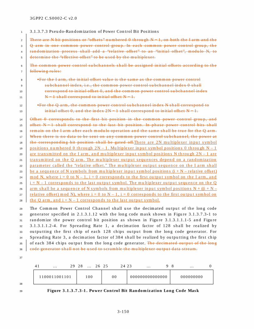
3GPP2 C.S0002-C v2.0
3-150
3.1.3.7.3 Pseudo-Randomization of Power Control Bit Positions 1
There are N bit positions or “offsets” numbered 0 through N − 1, on both the I arm and the 2
Q arm in one common power control group. In each common power control group, the 3
randomization process shall add a “relative offset” to an “initial offset”, modulo N, to 4
determine the “effective offset” to be used by the multiplexer. 5
The common power control subchannels shall be assigned initial offsets according to the 6
following rules: 7
•For the I arm, the initial offset value is the same as the common power control 8
subchannel index, i.e., the common power control subchannel index 0 shall 9
correspond to initial offset 0, and the common power control subchannel index 10
N − 1 shall correspond to initial offset N − 1. 11
•For the Q arm, the common power control subchannel index N shall correspond to 12
initial offset 0, and the index 2N − 1 shall correspond to initial offset N − 1. 13
Offset 0 corresponds to the first bit position in the common power control group, and 14
offset N − 1 shall correspond to the last bit position. In-phase power control bits shall 15
remain on the I arm after each modulo operation and the same shall be true for the Q arm. 16
When there is no data to be sent on any common power control subchannel, the power at 17
the corresponding bit position shall be gated off.There are 2N multiplexer input symbol 18
positions numbered 0 through 2N – 1. Multiplexer input symbol positions 0 through N – 1 19
are transmitted on the I arm, and multiplexer input symbol positions N through 2N – 1 are 20
transmitted on the Q arm. The multiplexer output sequences depend on a randomization 21
parameter called the “relative offset.” The multiplexer output sequence on the I arm shall 22
be a sequence of N symbols from multiplexer input symbol positions (i + N – relative offset) 23
mod N, where i = 0 to N – 1, i = 0 corresponds to the first output symbol on the I arm, and 24
i = N – 1 corresponds to the last output symbol. The multiplexer output sequence on the Q 25
arm shall be a sequence of N symbols from multiplexer input symbol positions N + ((i + N – 26
relative offset) mod N), where i = 0 to N – 1, i = 0 corresponds to the first output symbol on 27
the Q arm, and i = N – 1 corresponds to the last output symbol. 28
The Common Power Control Channel shall use the decimated output of the long code 29
generator specified in 2.1.3.1.12 with the long code mask shown in Figure 3.1.3.7.3-1 to 30
randomize the power control bit position as shown in Figure 3.1.3.1.1.1-5 and Figure 31
3.1.3.1.1.2-4. For Spreading Rate 1, a decimation factor of 128 shall be realized by 32
outputting the first chip of each 128 chips output from the long code generator. For 33
Spreading Rate 3, a decimation factor of 384 shall be realized by outputting the first chip 34
of each 384 chips output from the long code generator. The decimated output of the long 35
code generator shall not be used to scramble the multiplexer output data stream. 36
37
1100011001101 100 00 000000000000000 000000000
41 … 29 28 … 26 8 … 023 … 925 24
38
Figure 3.1.3.7.3-1. Power Control Bit Randomization Long Code Mask 39

3GPP2 C.S0002-C v2.0
3-151
1
The following algorithm shall be used to compute the relative offset using the long code 2
decimator output. The decimator output bit rate shall be 9600 bps, giving exactly N 3
scrambling bits in one common power control group. During the common power control 4
group, the N bits from the long code decimator are numbered from 0 through N − 1, with 5
bit 0 occurring first, and bit N − 1 occurring last. The last L bits from the decimator 6
appearing in the previous common power control group shall be used to compute the 7
relative offset for the current common power control group, where L is listed in Table 8
3.1.3.7.3-1. 9
10
Table 3.1.3.7.3-1. Parameters for Relative Offset Computation 11
PCG (ms)
Number of Offset Position Bits
(L)
First Offset Position Bits
(L1)
Second Offset Position Bits
(L2)
Computed Relative Offset
(P)
1.25 5 2 3 0 to 10
2.5 7 3 4 0 to 22
5.0 9 4 5 0 to 46
12
The L bits are separated into L1-bit and L2-bit blocks, with the L1-bit block occurring first. 13
The relative offset P is computed from the sum of P1 and P2, the unsigned binary integers 14
given by the L1-bit block and the L2-bit block, respectively, where the first bit in each 15
block is considered as the LSB. The value of the relative offset (P) is from 0 through N − 2 16
as shown in Table 3.1.3.7.3-1. 17
3.1.3.7.4 Common Power Control Channel Orthogonal and Quasi-Orthogonal Spreading 18
The Common Power Control Channel shall be spread by a Walsh function or quasi-19
orthogonal function as specified in 3.1.3.1.150. 20
3.1.3.7.5 Common Power Control Channel Quadrature Spreading 21
The Common Power Control Channel shall be PN spread, using the PN sequence specified 22
in 3.1.3.1.16. 23
3.1.3.7.6 Common Power Control Channel Filtering 24
Filtering for the Common Power Control Channel shall be as specified in 3.1.3.1.17. 25
3.1.3.7.7 Common Power Control Channel Transmission Processing 26
When the Physical Layer receives a PHY-CPCCH.Request(PN, CPCCH_ID, 27
RES_SCH_ADDR) from the MAC Layer, the base station shall perform the following: 28
• Store the arguments PN, CPCCH_ID, and RES_SCH_ADDR. 29
3GPP2 C.S0002-C v2.0
3-152
• For the base station with its pilot PN offset equal to the stored value of PN, set the 1
common power control subchannel index to RES_SCH_ADDR and compute the 2
relativeeffective offset for the common power control subchannel as specified in 3
3.1.3.7.3. 4
• Transmit the common power control subchannel with the relativeeffective offset 5
(computed in the previous step) on the Common Power Control Channel specified 6
by CPCCH_ID and the rate specified by CPCCH_RATE (see [5]). 7
3.1.3.8 Common Assignment Channel 8
The Common Assignment Channel is specifically designed to provide fast -response 9
reverse link channel assignments to support transmission of random access packets on 10
the reverse link. This channel controls the Reverse Common Control Channel and the 11
associated common power control subchannel in the Reservation Access Mode. It also 12
implements congestion control. The base station may choose not to support Common 13
Assignment Channels and inform the mobile stations on the Broadcast Control Channel of 14
this choice. 15
3.1.3.8.1 Common Assignment Channel Time Alignment and Modulation Rates 16
The base station shall transmit information on the Common Assignment Channel at a 17
fixed data rate of 9600 bps. The Common Assignment Channel frame length shall be 5 ms. 18
For a given base station, the I and Q channel pilot PN sequences for the Common 19
Assignment Channel shall use the same pilot PN sequence offset as for the Pilot Channel. 20
The Common Assignment Channel block interleaver shall always be aligned with the 21
Common Assignment Channel frame. 22
The base station shall support discontinuous transmission on the Common Assignment 23
Channel. The decision to enable or disable the Common Assignment Channel shall be 24
made by the base station on a frame-by-frame basis (i.e., 5 ms basis). 25
The start of the Common Assignment Channel block interleaver shall align with the start 26
of the zero-offset pilot PN sequence at every even-second time mark (t mod 100 = 0, where 27
t is the System Time in 20 ms frames). The first Common Assignment Channel frame shall 28
begin at the start of the base station transmission time. 29
3.1.3.8.2 Common Assignment Channel Structure 30
Common Assignment Channel frames shall consist of 48 bits. These 48 bits shall be 31
composed of 32 information bits followed by 8 frame quality indicator (CRC) bits and 8 32
Encoder Tail Bits, as shown in Figure 3.1.3.8.2-1. 33
34

3GPP2 C.S0002-C v2.0
3-153
Information Bits F T
Notation
F - Frame Quality Indicator (CRC)T - Encoder Tail Bits
1
Figure 3.1.3.8.2-1. Common Assignment Channel Frame Structure 2
3
3.1.3.8.2.1 Common Assignment Channel Frame Quality Indicator 4
The frame quality indicator (CRC) shall be calculated on all bits within the frame, except 5
the frame quality indicator itself and the Encoder Tail Bits. The generator polynomial for 6
the frame quality indicator shall be as follows: 7
g(x) = x8 + x7 + x4 + x3 + x + 1. 8
The frame quality indicators shall be computed according to the following procedure as 9
shown in Figure 3.1.3.8.2.1-1: 10
• Initially, all shift register elements shall be set to logical one and the switches shall 11
be set in the up position. 12
• The register shall be clocked a number of times equal to the number of information 13
bits in the frame with those bits as input. 14
• The switches shall be set in the down position so that the output is a modulo-2 15
addition with a ‘0’ and the successive shift register inputs are ‘0’s. 16
• The register shall be clocked an additional number of times equal to the number of 17
bits in the frame quality indicator (8). 18
• These additional bits shall be the frame quality indicator bits. 19
• The bits shall be transmitted in the order calculated. 20
21
0
Input
0
Output
Denotes one-bit storage element
Denotes modulo-2 addition
Up for the first 32 bits
Down for the last 8 bits
x0 x1 x2 x3 x4 x5 x6 x7
22
Figure 3.1.3.8.2.1-1. Common Assignment Channel Frame Quality Indicator 23
Calculation for the 8-Bit Frame Quality Indicator 24
25

3GPP2 C.S0002-C v2.0
3-154
3.1.3.8.2.2 Common Assignment Channel Encoder Tail Bits 1
The last eight bits of each Common Assignment Channel frame are called the Encoder Tail 2
Bits. These eight bits shall each be set to ‘0’. 3
3.1.3.8.3 Common Assignment Channel Convolutional Encoding 4
The Common Assignment Channel shall be convolutionally encoded as specified in 5
3.1.3.1.4. When generating Common Assignment Channel data, the encoder shall be 6
initialized to the all-zero state at the end of each frame. 7
3.1.3.8.4 Common Assignment Channel Interleaving 8
The modulation symbols shall be interleaved as specified in 3.1.3.1.7. 9
3.1.3.8.5 Common Assignment Channel Data Scrambling 10
The Common Assignment Channel shall be scrambled as specified in 3.1.3.1.9, using the 11
Common Assignment Channel long code mask which shall be as shown in Figure 12
3.1.3.8.5-1. 13
14
CACH_ID - Common Assignment Channel IDPILOT_PN - Pilot PN sequence offset index for the Forward CDMA Channel
1100011001101 01100 CACH_ID 000000000000 PILOT_PN
41 … 29 28 … 24 8 … 020 … 923 … 21
15
Figure 3.1.3.8.5-1. Common Assignment Channel Long Code Mask 16
17
3.1.3.8.6 Common Assignment Channel Orthogonal and Quasi-Orthogonal Spreading 18
The Common Assignment Channel shall be spread by a Walsh function or quasi-19
orthogonal function as specified in 3.1.3.1.150. 20
3.1.3.8.7 Common Assignment Channel Quadrature Spreading 21
The Common Assignment Channel shall be PN spread, using the PN sequence specified in 22
3.1.3.1.16. 23
3.1.3.8.8 Common Assignment Channel Filtering 24
Filtering for tThe Common Assignment Channel shall be filtered as specified in 3.1.3.1.17. 25
3.1.3.8.9 Common Assignment Channel Transmission Processing 26
When the Physical Layer receives a PHY-CACH.Request(SDU, CACH_ID, NUM_BITS) from 27
the MAC Layer, the base station shall: 28
• Store the arguments SDU, CACH_ID, and NUM_BITS; 29

3GPP2 C.S0002-C v2.0
3-155
• Set the information bits (see Figure 3.1.3.8.2-1) to SDU; 1
• Transmit a Common Assignment Channel frame. 2
3.1.3.9 Forward Common Control Channel 3
The Forward Common Control Channel is an encoded, interleaved, spread, and modulated 4
spread spectrum signal that is used by mobile stations operating within the coverage area 5
of the base station. The base station uses the Forward Common Control Channel to 6
transmit mobile station-specific messages. 7
3.1.3.9.1 Forward Common Control Channel Time Alignment and Modulation Rates 8
The Forward Common Control Channel shall be transmitted at a variable data rate of 9
9600, 19200, or 38400 bps. A Forward Common Control Channel frame is 20, 10, or 5 ms 10
in duration. Although the data rate of the Forward Common Control Channel is variable 11
from frame to frame, the data rate transmitted to a mobile station in a given frame is 12
predetermined and known to that mobile station. 13
For a given base station, the I and Q channel pilot PN sequences for the Forward Common 14
Control Channel shall use the same pilot PN sequence offset as for the Forward Pilot 15
Channel. 16
The start of the interleaver block and the frame of the Forward Common Control Channel 17
shall align with the start of the zero-offset pilot PN sequence at every even-second time 18
mark (t mod 100 = 0, where t is the System Time in 20 ms frames) as shown in Figure 19
3.1.3.2.1-1. The first Forward Common Control Channel frame shall begin at the start of 20
base station transmission time (see 3.1.5). 21
3.1.3.9.2 Forward Common Control Channel Structure 22
Table 3.1.3.9.2-1 specifies the Forward Common Control Channel bit allocations, and the 23
structure is shown in Figure 3.1.3.9.2-1. 24
All frames shall consist of the information bits, followed by a frame quality indicator (CRC) 25
and eight Encoder Tail Bits. 26
The Forward Common Control Channel shall be divided into Forward Common Control 27
Channel slots that are each 80 ms in duration. 28
29
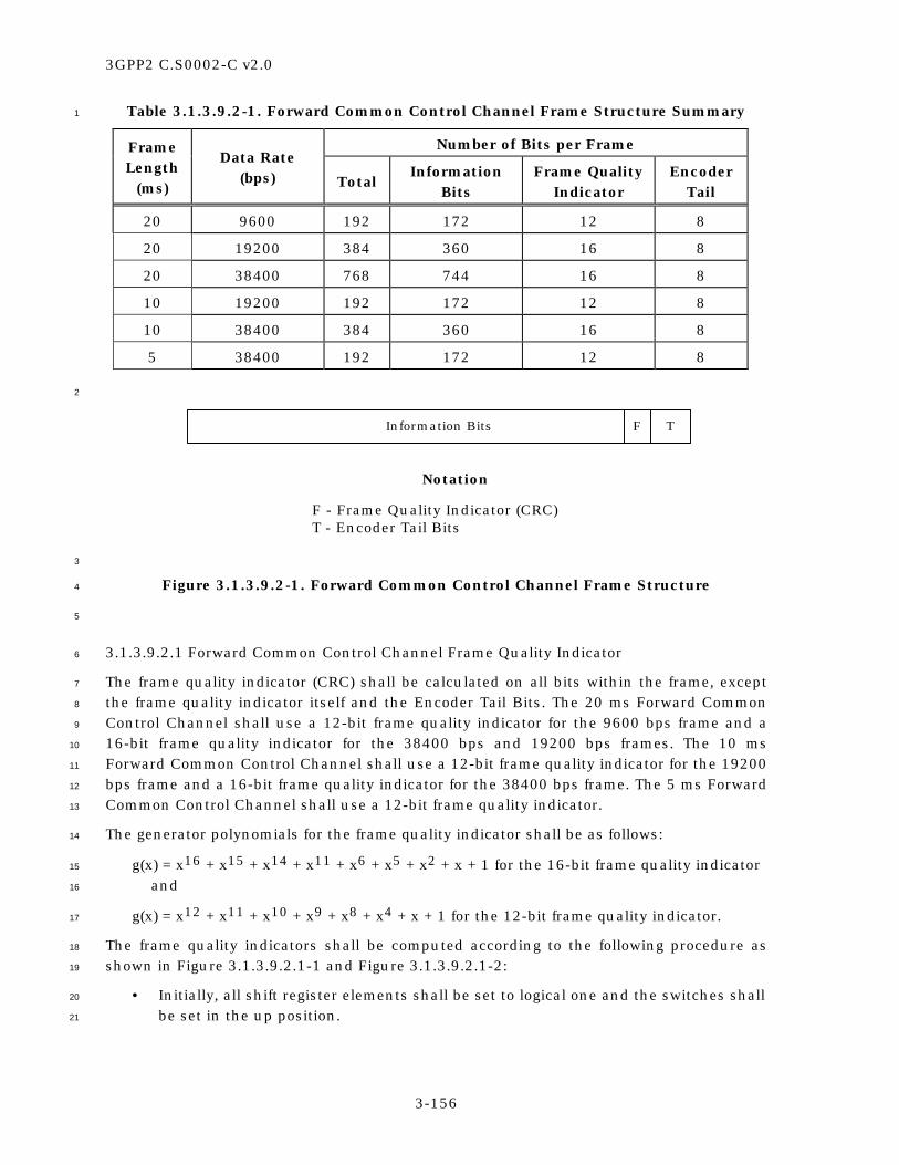
3GPP2 C.S0002-C v2.0
3-156
Table 3.1.3.9.2-1. Forward Common Control Channel Frame Structure Summary 1
Number of Bits per Frame Frame Length
(ms)
Data Rate (bps) Total
Information Bits
Frame Quality Indicator
Encoder Tail
20 9600 192 172 12 8
20 19200 384 360 16 8
20 38400 768 744 16 8
10 19200 192 172 12 8
10 38400 384 360 16 8
5 38400 192 172 12 8
2
Information Bits F T
Notation
F - Frame Quality Indicator (CRC)T - Encoder Tail Bits
3
Figure 3.1.3.9.2-1. Forward Common Control Channel Frame Structure 4
5
3.1.3.9.2.1 Forward Common Control Channel Frame Quality Indicator 6
The frame quality indicator (CRC) shall be calculated on all bits within the frame, except 7
the frame quality indicator itself and the Encoder Tail Bits. The 20 ms Forward Common 8
Control Channel shall use a 12-bit frame quality indicator for the 9600 bps frame and a 9
16-bit frame quality indicator for the 38400 bps and 19200 bps frames. The 10 ms 10
Forward Common Control Channel shall use a 12-bit frame quality indicator for the 19200 11
bps frame and a 16-bit frame quality indicator for the 38400 bps frame. The 5 ms Forward 12
Common Control Channel shall use a 12-bit frame quality indicator. 13
The generator polynomials for the frame quality indicator shall be as follows: 14
g(x) = x16 + x15 + x14 + x11 + x6 + x5 + x2 + x + 1 for the 16-bit frame quality indicator 15
and 16
g(x) = x12 + x11 + x10 + x9 + x8 + x4 + x + 1 for the 12-bit frame quality indicator. 17
The frame quality indicators shall be computed according to the following procedure as 18
shown in Figure 3.1.3.9.2.1-1 and Figure 3.1.3.9.2.1-2: 19
• Initially, all shift register elements shall be set to logical one and the switches shall 20
be set in the up position. 21

3GPP2 C.S0002-C v2.0
3-157
• The register shall be clocked a number of times equal to the number of information 1
bits in the frame with those bits as input. 2
• The switches shall be set in the down position so that the output is a modulo-2 3
addition with a ‘0’ and the successive shift register inputs are ‘0’s. 4
• The register shall be clocked an additional number of times equal to the number of 5
bits in the frame quality indicator (16 or 12). 6
• These additional bits shall be the frame quality indicator bits. 7
• The bits shall be transmitted in the order calculated. 8
9
0
Input
0
Output
Denotes one-bit storage element
Denotes modulo-2 addition
Up for the information bitsDown for the last 16 bits
x0 x6 x14x11 x15x1 x2 x5
10
Figure 3.1.3.9.2.1-1. Forward Common Control Channel Frame Quality Indicator 11
Calculation for the 16-Bit Frame Quality Indicator 12
13
0
Input
0
Output
Denotes one-bit storage element
Denotes modulo-2 addition
Up for the information bitsDown for the last 12 bits
x0 x1 x4 x9x8 x10 x11
14
Figure 3.1.3.9.2.1-2. Forward Common Control Channel Frame Quality Indicator 15
Calculation for the 12-Bit Frame Quality Indicator 16
17
3.1.3.9.2.2 Forward Common Control Channel Encoder Tail Bits 18
The last eight bits of each Forward Common Control Channel frame are called the Encoder 19
Tail Bits. These eight bits shall each be set to ‘0’. 20
3.1.3.9.3 Forward Common Control Channel Encoding 21
The Forward Common Control Channel data shall be encoded as specified in 3.1.3.1.4. 22
When generating Forward Common Control Channel data, the encoder shall be initialized 23
to the all-zero state at the end of each 5, 10, or 20 ms frame. 24

3GPP2 C.S0002-C v2.0
3-158
3.1.3.9.4 Forward Common Control Channel Interleaving 1
The modulation symbols on the Forward Common Control Channel shall be interleaved, 2
as specified in 3.1.3.1.7. The interleaver block shall align with the Forward Common 3
Control Channel frame. 4
3.1.3.9.5 Forward Common Control Channel Data Scrambling 5
The Forward Common Control Channel data shall be scrambled as specified in 3.1.3.1.9 6
utilizing the Forward Common Control Channel long code mask as shown in Figure 7
3.1.3.9.5-1. 8
9
1100011001101 01000 000 000000000000 000000000
41 … 29 28 … 24 8 … 020 … 923 … 21
10
Figure 3.1.3.9.5-1. Forward Common Control Channel Long Code Mask 11
12
3.1.3.9.6 Forward Common Control Channel Orthogonal and Quasi-Orthogonal Spreading. 13
The Forward Common Control Channel shall be spread by a Walsh function or quasi-14
orthogonal function as specified in 3.1.3.1.150. 15
3.1.3.9.7 Forward Common Control Channel Quadrature Spreading 16
The Forward Common Control Channel shall be PN spread, using the PN sequence 17
specified in 3.1.3.1.16. 18
3.1.3.9.8 Forward Common Control Channel Filtering 19
Filtering for tThe Forward Common Control Channel shall be filtered as specified in 20
3.1.3.1.17. 21
3.1.3.9.9 Forward Common Control Channel Transmission Processing 22
When the Physical Layer receives a PHY-FCCCH.Request(SDU, FCCCH_ID, 23
FRAME_DURATION, NUM_BITS) from the MAC Layer, the base station shall: 24
• Store the arguments SDU, FCCCH_ID, FRAME_DURATION, and NUM_BITS; 25
• Set the information bits (see Figure 3.1.3.9.2-1) to SDU; 26
• Transmit a Forward Common Control Channel frame of duration 27
FRAME_DURATION (5 ms, 10 ms, or 20 ms) at a data rate that corresponds to 28
NUM_BITS and FRAME_DURATION as specified in Table 3.1.3.9.2-1. 29
3.1.3.10 Forward Packet Data Control Channel 30
The Forward Packet Data Control Channel is used by the base station for transmitting 31
control information for the associated Forward Packet Data Channel or transmitting a 32

3GPP2 C.S0002-C v2.0
3-159
Walsh mask to the mobile station with Spreading Rate 1. A forward CDMA channel may 1
contain up to two Forward Packet Data Control Channels. The Forward Packet Data 2
Control Channels are identified by a channel identifier (PDCCH_ID), which is set to ‘0’ for 3
the first Forward Packet Data Control Channel and to ‘1’ for the second Forward Packet 4
Data Control Channel, if supported. 5
If the base station supports one Forward Packet Data Channel with Radio Configuration 6
10, the base station shall support one or two Forward Packet Data Control Channels. If 7
the base station supports two Forward Packet Data Channels with Radio Configuration 10, 8
the base station shall support two Forward Packet Data Control Channels. 9
3.1.3.10.1 Forward Packet Data Control Channel Time Alignment, and Modulation Rates 10
The base station shall transmit on the Forward Packet Data Control Channel at variable 11
data rates of 29600, 14800, and 7400 bps depending on the frame duration. The frame 12
duration is NUM_SLOTS (NUM_SLOTS = 1, 2, or 4) 1.25-ms slots. All Forward Packet Data 13
Control Channels and Forward Packet Data Channels transmitted simultaneously shall 14
start their transmissions at the same time (SYS_TIME) and have the same durations. 15
16
For a given base station, the I and Q pilot PN sequences for the Forward Packet Data 17
Control Channel shall use the same pilot PN sequence offset as for the Forward Pilot 18
Channel. 19
The modulation symbols transmitted on the first Forward Packet Data Control Channel 20
(PDCCH_ID = ‘0’) should be transmitted using at least as much energy as the modulation 21
symbols transmitted on the second Forward Packet Data Control Channel (PDCCH_ID = 22
‘1’) that is being transmitted simultaneously. 23
24
3.1.3.10.2 Forward Packet Data Control Channel Frame Structure 25
The information transmitted on the Forward Packet Data Control Channel consists of the 26
scrambled SDU[8…2012:0] and the frame quality indicator-covered SDU[0…720:13], 27
where SDU is a parameter passed by the MAC Layer in the PHY-FPDCCH.Request 28
primitive. 29
The Forward Packet Data Control Channel frame shall consists of the scrambled 30
SDU[8…2012:0], the 8-bit frame quality indicator-covered SDU[0…720:13], the 8-bit inner 31
frame quality indicator (CRC), and the eight Encoder Tail Bits, as shown in Figure 32
3.1.3.10.2-1. 33
34

3GPP2 C.S0002-C v2.0
3-160
Encoder TailBits
(8 Bits)
Inner FrameQuality
Indicator(8 Bits)
Frame QualityIndicator-Covered
SDU[0...7](8 Bits)
Scrambled SDU[8...20](13 Bits)
21 Bits Used toCalculate the Inner
Frame Quality Indicator
13 Bits Used toCalculate the Outer
Frame Quality Indicator
1
Figure 3.1.3.10.2-1. Forward Packet Data Control Channel Frame Structure 2
3
3.1.3.10.2.1 Forward Packet Data Control Channel Scrambling 4
SDU[8…2012:0] (see Figure 3.1.3.10.2-1) shall be scrambled by bit-by-bit modulo-2 5
adding a 13-bit scrambler sequence. The scrambler sequence shall be equal to the 13 6
least significant bits of (SYS_TIME + NUM_SLOTS), where SYS_TIME is the system time in 7
units of 1.25 ms of the first slot of the Forward Packet Data Control Channel transmission. 8
The bit-by-bit modulo-2 additions shall be such that SDU[8] is added to the most 9
significant bit of the scrambler sequence and SDU[20] to the least significant bit of the 10
scrambler sequence.The first bit of the scrambler sequence shall be the least significant 11
bit. 12
3.1.3.10.2.2 Frame Quality Indicator-Covered SDU[0…720:13] for the Forward Packet Data 13
Control Channel 14
The 8-bit frame quality indicator-covered SDU[0…720:13] shall be generated by 15
performing the modulo-2 addition of the SDU[0…720:13] passed by the MAC Layer with 16
an outer frame quality indicator, which is calculated on the scrambled SDU[8…2012:0]. 17
The generator polynomial for the outer frame quality indicator shall be as follows: 18
g(x) = x8 + x2 + x + 1. 19
The frame quality indicator-covered SDU[0…720:13] shall be computed according to the 20
following procedure as shown in Figure 3.1.3.10.2.2-1. 21
• Initially, all shift register elements shall be set to logical one and the switches shall 22
be set in the up position. 23
• The register shall be clocked once for each of the first 13 scrambled input bits of 24
the Forward Packet Data Control Channel frame with those bits as input. The first 25
input bit to the generator of the outer frame quality indicator shall be the 26
scrambled SDU[8] and the last input bit shall be the scrambled SDU[20]. 27
• Then, the switches shall be set in the down position so that the output is a 28
modulo-2 addition with the 8-bit SDU[0…720:13] and the successive shift register 29
inputs are ‘0’s. The bit-by-bit modulo-2 addition of the SDU[0…7] with the outer 30
frame quality indicator shall be such that SDU[0] is added to the first output bit of 31
the outer frame quality indicator and SDU[7] to the last output bit of the outer 32
frame quality indicator. 33

3GPP2 C.S0002-C v2.0
3-161
• The register shall be clocked an additional eight times. 1
• The frame quality indicator-covered SDU[0] shall be output followed by the frame 2
quality indicator-covered SDU[1], etc. 3
•These additional bits shall be the frame quality indicator-covered SDU[20:13] field. 4
•The bits shall be transmitted in the order calculated. 5
6
Input
Output
SDU[0...7]
'0'
Up for the 13 scrambled bits; then,down for the 8-bit frame quality
indicator-covered SDU[0...7]
x0 x2 x7x5 x6x4x3x1
7
Figure 3.1.3.10.2.2-1. Generation of the Frame Quality Indicator-Covered 8
SDU[20:13] for the Forward Packet Data Control Channel 9
10
3.1.3.10.2.3 Forward Packet Data Control Channel Inner Frame Quality Indicator 11
The inner frame quality indicator (CRC) shall be calculated on all bits within the frame, 12
except the inner frame quality indicator itself and the Encoder Tail Bits. The Forward 13
Packet Data Control Channel shall use an 8-bit inner frame quality indicator. 14
The generator polynomial for the inner frame quality indicator shall be as follows: 15
g(x) = x8 + x7 + x4 + x3 + x + 1. 16
The inner frame quality indicator shall be computed according to the following procedure 17
as shown in Figure 3.1.3.10.2.3-1. 18
• If the frame duration of the Forward Packet Data Control Channel is 1.25 or 2.5 19
ms, all shift register elements shall be initialized to logical one and the switches 20
shall be set in the up position. If the frame duration of the Forward Packet Data 21
Control Channel is 5 ms, all shift register elements shall be initialized to logical 22
zero and the switches shall be set in the up position. 23
• The register shall be clocked once for each of the first 21 bits of the Forward Packet 24
Data Control Channel frame with those bits as input. 25
• The switches shall be set in the down position so that the output is a modulo-2 26
addition with a ‘0’ and the successive shift register inputs are ‘0’s. 27
• The register shall be clocked an additional eight times. 28
• These additional bits shall be the inner frame quality indicator bits. 29

3GPP2 C.S0002-C v2.0
3-162
• The bits shall be transmitted in the order calculated. 1
2
Input
Output
'0'
'0'
Up for the first 21 bits;then, down for the 8-bit
inner frame quality indicator field
x0 x2 x7x5 x6x4x3x1
3
Figure 3.1.3.10.2.3-1. Forward Packet Data Control Channel Inner Frame Quality 4
Indicator Calculation 5
6
3.1.3.10.3 Forward Packet Data Control Channel Encoder Tail Bits 7
The last eight bits of each Forward Packet Data Control Channel frame are called the 8
Encoder Tail Bits. These eight bits shall each be set to ‘0’. 9
3.1.3.10.4 Forward Packet Data Control Channel Convolutional Encoding 10
The Forward Packet Data Control Channel shall be convolutionally encoded as specified in 11
3.1.3.1.4. When generating Forward Packet Data Control Channel data, the encoder shall 12
be initialized to the all-zero state at the end of each frame. 13
3.1.3.10.5 Forward Packet Data Control Channel Code Symbol Repetition 14
Forward Packet Data Control Channel code symbol repetition shall be as specified in 15
3.1.3.1.5. 16
3.1.3.10.6 Forward Packet Data Control Channel Puncturing 17
Code symbols resulting from the symbol repetition shall be punctured as specified in 18
3.1.3.1.6. 19
3.1.3.10.7 Forward Packet Data Control Channel Interleaving 20
The modulation symbols on the Forward Packet Data Control Channel shall be 21
interleaved, as specified in 3.1.3.1.7. The interleaver block shall align with the Forward 22
Packet Data Control Channel frame. 23
3.1.3.10.8 Forward Packet Data Control Channel Orthogonal Spreading 24
The Forward Packet Data Control Channel shall be spread by a Walsh function as 25
specified in 3.1.3.1.150. 26

3GPP2 C.S0002-C v2.0
3-163
3.1.3.10.9 Forward Packet Data Control Channel Quadrature Spreading 1
The Forward Packet Data Control Channel shall be PN spread as specified in 3.1.3.1.16. 2
3.1.3.10.10 Forward Packet Data Control Channel Filtering 3
Filtering for tThe Forward Packet Data Control Channel shall be filtered as specified in 4
3.1.3.1.17. 5
3.1.3.10.11 Forward Packet Data Control Channel Transmission Processing 6
When the Physical Layer receives a PHY-FPDCCH.Request(PDCCH_ID, SDU, NUM_SLOTS, 7
SYS_TIME) from the MAC Layer, the base station shall: 8
• Store the arguments PDCCH_ID, SDU, NUM_SLOTS, and SYS_TIME. 9
• Scramble SDU[8…2012:0] as specified in 3.1.3.10.2.1. 10
• Use the scrambled SDU[8…2012:0] and the SDU[0…720:13] to compute thean 8-11
bit frame quality indicator-covered SDU[0…720:13] as specified in 3.1.3.10.2.2. 12
• Transmit the scrambled SDU[8…2012:0], the computed frame quality indicator-13
covered SDU[0…720:13], thea computed 8-bit inner frame quality indicator, and 14
eight Encoder Tail Bits on the Forward Packet Data Control Channel with identifier 15
PDCCH_ID and frame of duration NUM_SLOTS starting at SYS_TIME. 16
3.1.3.11 Forward Dedicated Control Channel 17
The Forward Dedicated Control Channel is used for the transmission of user and signaling 18
information to a specific mobile station during a call. Each Forward Traffic Channel may 19
contain one Forward Dedicated Control Channel. 20
3.1.3.11.1 Forward Dedicated Control Channel Time Alignment and Modulation Rates 21
The base station shall transmit information on the Forward Dedicated Control Channel at 22
a fixed data rate. 23
A Forward Dedicated Control Channel frame shall be 5 or 20 ms in duration. 24
The base station shall transmit information on the Forward Dedicated Control Channel at 25
a fixed data rate of 9600 bps for Radio Configurations 3, 4, 6, and 7. If flexible data rates 26
are supported for 20 ms frames, a fixed data rate between 1050 and 9600 bps can be used 27
for the Forward Dedicated Control Channel in Radio Configurations 3, 4, 6, and 7. 28
The base station shall transmit information on the Forward Dedicated Control Channel at 29
a fixed data rate of 14400 bps for 20 ms frames and 9600 bps for 5 ms frames for Radio 30
Configurations 5, 8, and 9. The base station may support flexible data rates. If flexible 31
data rates are supported for 20 ms frames, a fixed data rate between 1050 and 14400 bps 32
can be used for the Forward Dedicated Control Channel in Radio Configurations 5, 8, and 33
9. 34
For a given base station, the I and Q channel pilot PN sequences for the Forward 35
Dedicated Control Channel shall use the same pilot PN sequence offset as for the Forward 36
Pilot Channel. 37

3GPP2 C.S0002-C v2.0
3-164
The base station shall support discontinuous transmission on the Forward Dedicated 1
Control Channel. The decision to enable or disable transmission shall be made on a 2
frame-by-frame (i.e., 5 or 20 ms) basis. 3
The base station may support Forward Dedicated Control Channel frames that are time 4
offset by multiples of 1.25 ms. The amount of the time offset is specified by 5
FRAME_OFFSET. A zero-offset 20 ms Forward Dedicated Control Channel frame shall 6
begin only when System Time is an integral multiple of 20 ms (see Figure 1.3-1). A zero-7
offset 5 ms Forward Dedicated Control Channel frame shall begin only when System Time 8
is an integral multiple of 5 ms. An offset 20 ms Forward Dedicated Control Channel frame 9
shall begin 1.25 × FRAME_OFFSET ms later than the zero-offset 20 ms Forward Dedicated 10
Control Channel frame. An offset 5 ms Forward Dedicated Control Channel frame shall 11
begin 1.25 × (FRAME_OFFSET mod 4) ms later than the zero-offset 5 ms Forward 12
Dedicated Control Channel frame. The interleave block for the Forward Dedicated Control 13
Channel shall be aligned with the Forward Dedicated Control Channel frame. 14
3.1.3.11.2 Forward Dedicated Control Channel Frame Structure 15
Table 3.1.3.11.2-1 specifies the Forward Dedicated Control Channel bit allocations. Table 16
3.1.3.11.2-2 specifies the Forward Dedicated Control Channel bit allocations for flexible 17
data rates. All frames that carry data shall consist of zero or one Reserved Bits and the 18
information bits followed by a frame quality indicator (CRC) and eight Encoder Tail Bits, as 19
shown in Figure 3.1.3.11.2-1. 20
21
Table 3.1.3.11.2-1. Forward Dedicated Control Channel Frame Structure Summary 22
for Non-flexible Data Rates 23
Number of Bits per Frame
Radio Config.
Frame Length
(ms)
Data Rate (bps) Total Reserved Information
Frame Quality
Indicator
Encoder Tail
3 4, 6, and 7
20 9600 192 0 172 12 8
5, 8, and 9
20 14400 288 1 267 12 8
3, 4, 5, 6, 7, 8, and 9
5 9600 48 0 24 16 8
24

3GPP2 C.S0002-C v2.0
3-165
Table 3.1.3.11.2-2. Forward Dedicated Control Channel Frame Structure Summary 1
for Flexible Data Rates 2
Number of Bits per Frame
Radio Config.
Frame Length
(ms)
Data Rate (bps) Total Information
Frame Quality
Indicator
Encoder Tail
20 1250 to 9600 25 to 192 1 to 168 16 8 3, 4, 6, and 7 20 1050 to 9550 21 to 191 1 to 171 12 8
20 1250 to 14400 25 to 288 1 to 264 16 8 5, 8, and 9 20
1050 to 14300, 14400
21 to 286, 288
1 to 266, 268 12 8
3
Information Bits F TR
Notation
R - Reserved BitF - Frame Quality Indicator (CRC)T - Encoder Tail Bits
4
Figure 3.1.3.11.2-1. Forward Dedicated Control Channel Frame Structure 5
6
3.1.3.11.2.1 Forward Dedicated Control Channel Frame Quality Indicator 7
The frame quality indicator (CRC) shall be calculated on all bits within the frame, except 8
the frame quality indicator itself and the Encoder Tail Bits. The 20 ms Forward Dedicated 9
Control Channel shall use a 12-bit frame quality indicator. If flexible data rates are 10
supported, a 16-bit frame quality indicator may be used. The 5 ms Forward Dedicated 11
Control Channel shall use a 16-bit frame quality indicator. 12
The generator polynomials for the frame quality indicator shall be as follows: 13
g(x) = x16 + x15 + x14 + x11 + x6 + x5 + x2 + x + 1 for the 16-bit frame quality indicator 14
and 15
g(x) = x12 + x11 + x10 + x9 + x8 + x4 + x + 1 for the 12-bit frame quality indicator. 16
The frame quality indicators shall be computed according to the following procedure as 17
shown in Figure 3.1.3.11.2.1-1 and Figure 3.1.3.11.2.1-2: 18
• Initially, all shift register elements shall be set to logical one and the switches shall 19
be set in the up position. 20
• The register shall be clocked a number of times equal to the number of reserved 21
and information bits in the frame with those bits as input. 22

3GPP2 C.S0002-C v2.0
3-166
• The switches shall be set in the down position so that the output is a modulo-2 1
addition with a ‘0’ and the successive shift register inputs are ‘0’s. 2
• The register shall be clocked an additional number of times equal to the number of 3
bits in the frame quality indicator (16 or 12). 4
• These additional bits shall be the frame quality indicator bits. 5
• The bits shall be transmitted in the order calculated. 6
7
0
Input
0
Output
Denotes one-bit storage element
Denotes modulo-2 addition
Up for theinformation bits andthe reserved bitDown for the last 16 bits
x0 x6 x14x11 x15x1 x2 x5
8
Figure 3.1.3.11.2.1-1. Forward Dedicated Control Channel Frame Quality Indicator 9
Calculation for the 16-Bit Frame Quality Indicator 10
11
0
Input
0
Output
Denotes one-bit storage element
Denotes modulo-2 additionUp for the information bits and the reserved bitDown for the last 12 bits
x0 x1 x4 x9x8 x10 x11
12
Figure 3.1.3.11.2.1-2. Forward Dedicated Control Channel Frame Quality Indicator 13
Calculation for the 12-Bit Frame Quality Indicator 14
15
3.1.3.11.2.2 Forward Dedicated Control Channel Encoder Tail Bits 16
The last eight bits of each Forward Dedicated Control Channel frame are called the 17
Encoder Tail Bits. These eight bits shall each be set to ‘0’. 18
3.1.3.11.2.3 Forward Dedicated Control Channel Reserved Bit 19
This bit is reserved and shall be set to ‘0’. 20
3.1.3.11.3 Forward Dedicated Control Channel Convolutional Encoding 21
The Forward Dedicated Control Channel shall be convolutionally encoded as specified in 22
3.1.3.1.4. 23
When generating Forward Dedicated Control Channel data, the encoder shall be initialized 24
to the all-zero state at the end of each 5 or 20 ms frame. 25

3GPP2 C.S0002-C v2.0
3-167
3.1.3.11.4 Forward Dedicated Control Channel Code Symbol Repetition 1
Forward Dedicated Control Channel code symbol repetition shall be as specified in 2
3.1.3.1.5. 3
3.1.3.11.5 Forward Dedicated Control Channel Puncturing 4
Code symbols resulting from the symbol repetition shall be punctured as specified in 5
3.1.3.1.6. 6
3.1.3.11.6 Forward Dedicated Control Channel Interleaving 7
The modulation symbols shall be interleaved as specified in 3.1.3.1.7. 8
3.1.3.11.7 Forward Dedicated Control Channel Data Scrambling 9
The Forward Dedicated Control Channel shall be scrambled as specified in 3.1.3.1.9. The 10
public long code mask shall be specified by PLCM_42 (see 2.3.6 in [5]) as shown in Figure 11
3.1.3.11.7-1. The generation of the private long code mask shall be as specified in 12
2.1.3.1.12. 13
14
11000 PLCM_37
41 … 37 36 … 0
15
Figure 3.1.3.11.7-1. Forward Dedicated Control Channel Public Long Code Mask 16
17
3.1.3.11.8 Forward Dedicated Control Channel Power Control Subchannel 18
If the fForward pPower cControl sSubchannel is enabled on the Forward Dedicated 19
Control Channel (FPC_PRI_CHANNEL = ‘1’), the base station shall transmit continuously a 20
fForward pPower cControl sSubchannel on the Forward Dedicated Control Channel as 21
specified in 3.1.3.1.11. 22
3.1.3.11.9 Forward Dedicated Control Channel Orthogonal and Quasi-Orthogonal 23
Spreading 24
The Forward Dedicated Control Channel shall be spread by a Walsh function or quasi-25
orthogonal function as specified in 3.1.3.1.150. 26
3.1.3.11.10 Forward Dedicated Control Channel Quadrature Spreading 27
The Forward Dedicated Control Channel shall be PN spread as specified in 3.1.3.1.16. 28
3.1.3.11.11 Forward Dedicated Control Channel Filtering 29
Filtering for tThe Forward Dedicated Control Channel shall be filtered as specified in 30
3.1.3.1.17. 31
3GPP2 C.S0002-C v2.0
3-168
3.1.3.11.12 Forward Dedicated Control Channel Transmission Processing 1
When the Physical Layer receives a PHY-DCCH.Request(SDU, FRAME_DURATION, 2
NUM_BITS) from the MAC Layer, the base station shall perform the following: 3
• Store the arguments SDU, FRAME_DURATION, and NUM_BITS. 4
• If SDU is not equal to NULL, set the information bits to SDU. 5
• If SDU is not equal to NULL, transmit NUM_BITS bits of SDU in a Forward 6
Dedicated Control Channel frame of duration FRAME_DURATION (5 ms or 20 ms). 7
If a PHY-DCCH.Request primitive for a 5 ms frame is received coincident with a 8
PHY-DCCH.Request primitive for a 20 ms frame or during transmission of a 20 ms 9
frame, then the base station may preempt transmission of the 20 ms frame and 10
transmit a 5 ms frame. Transmission of the 20 ms frame may start or resume after 11
completion of the 5 ms frame. 12
3.1.3.12 Forward Fundamental Channel 13
The Forward Fundamental Channel is used for the transmission of user and signaling 14
information to a specific mobile station during a call. Each Forward Traffic Channel may 15
contain one Forward Fundamental Channel. 16
3.1.3.12.1 Forward Fundamental Channel Time Alignment and Modulation Rates 17
When operating in Radio Configuration 1, the base station shall transmit information on 18
the Forward Fundamental Channel at variable data rates of 9600, 4800, 2400, and 1200 19
bps. 20
When operating in Radio Configuration 2, the base station shall transmit information on 21
the Forward Fundamental Channel at variable data rates of 14400, 7200, 3600, and 1800 22
bps. 23
When operating in Radio Configurations 3, 4, 6, or 7, the base station shall transmit 24
information on the Forward Fundamental Channel at variable data rates of 9600, 4800, 25
2700, and 1500 bps during 20 ms frames or at 9600 bps during 5 ms frames. The base 26
station may support flexible data rates. If flexible data rates are supported for 20 ms 27
frames, the base station should support variable rates corresponding to 1 to 171 28
information bits per 20 ms frame on the Forward Fundamental Channel. The minimum 29
number of flexible data rates used in variable rate operation is not specified. 30
When operating in Radio Configurations 5, 8, or 9, the base station shall transmit 31
information on the Forward Fundamental Channel at variable data rates of 14400, 7200, 32
3600, and 1800 bps during 20 ms frames or at 9600 bps during 5 ms frames. If flexible 33
data rates are supported, the base station should support variable rates corresponding to 34
1 to 268 information bits per 20 ms frame on the Forward Fundamental Channel. The 35
minimum number of flexible data rates used in variable rate operation is not specified. 36
Forward Fundamental Channel frames with Radio Configurations 1 and 2 shall be 20 ms 37
in duration. Forward Fundamental Channel frames with Radio Configurations 3 through 9 38
shall be 5 or 20 ms in duration. The data rate and frame duration on a Forward 39
Fundamental Channel within a radio configuration shall be selected on a frame-by-frame 40

3GPP2 C.S0002-C v2.0
3-169
basis. Although the data rate may vary on a frame-by-frame basis, the modulation symbol 1
rate is kept constant by code repetition for data rates lower than the maximum. A base 2
station operating with Radio Configurations 3 through 9 may discontinue transmission of 3
the Forward Fundamental Channel for up to three 5 ms frames in a 20 ms frame. 4
For a given base station, the I and Q channel pilot PN sequences for the Forward 5
Fundamental Channel shall use the same pilot PN sequence offset as for the Forward Pilot 6
Channel. 7
The modulation symbols that are transmitted at lower data rates shall be transmitted 8
using lower energy. Specifically, the energy per modulation symbol (Es) for the supported 9
data rates should be: 10
Es = Emax × R / Rmax 11
where Emax is the energy per symbol at the maximum data rate for the Forward 12
Fundamental Channel with the associated radio configuration, R is the data rate, and 13
Rmax is the maximum data rate for the Forward Fundamental Channel for the associated 14
radio configuration. For example, when transmitting a Radio Configuration 1 frame at 15
4800 bps, the energy per symbol should be one half the energy per symbol in a 9600 bps 16
frame. 17
The base station may support Forward Fundamental Channel frames that are time offset 18
by multiples of 1.25 ms. The amount of the time offset is specified by FRAME_OFFSET. A 19
zero-offset 20 ms Forward Fundamental Channel frame shall begin only when System 20
Time is an integral multiple of 20 ms (see Figure 1.3-1). A zero-offset 5 ms Forward 21
Fundamental Channel frame shall begin only when System Time is an integral multiple of 22
5 ms. An offset 20 ms Forward Fundamental Channel frame shall begin 1.25 × 23
FRAME_OFFSET ms later than the zero-offset 20 ms Forward Fundamental Channel 24
frame. An offset 5 ms Forward Fundamental Channel frame shall begin 1.25 × 25
(FRAME_OFFSET mod 4) ms later than the zero-offset 5 ms Forward Fundamental 26
Channel frame. The interleaver block for the Forward Fundamental Channel shall be 27
aligned with the Forward Fundamental Channel frame. 28
3.1.3.12.2 Forward Fundamental Channel Frame Structure 29
Table 3.1.3.12.2-1 summarizes the Forward Fundamental Channel bit allocations. Table 30
3.1.3.12.2-2 and Table 3.1.3.12.2-3 summarize the Forward Fundamental Channel bit 31
allocations for flexible data rates. The order of the bits is shown in Figure 3.1.3.12.2-1. 32
The 2400 and 1200 bps frames with Radio Configuration 1 shall consist of the information 33
bits followed by 8 Encoder Tail Bits. All frames with Radio Configurations 3, 4, 6, and 7, 34
and the 9600 and 4800 bps frames with Radio Configuration 1, shall consist of the 35
information bits followed by a frame quality indicator (CRC) and 8 Encoder Tail Bits. All 36
frames with Radio Configurations 2, 5, 8, and 9 shall consist of zero or one Reserved/Flag 37
Bits followed by the information bits, a frame quality indicator (CRC), and 8 Encoder Tail 38
Bits. 39
40

3GPP2 C.S0002-C v2.0
3-170
Table 3.1.3.12.2-1. Forward Fundamental Channel Frame Structure Summary for 1
Non-flexible Data Rates 2
Number of Bits per Frame
Radio Config.
Data Rate (bps) Total
Reserved/ Flag
Informa-tion
Frame Quality
Indicator
Encoder Tail
9600 192 0 172 12 8
4800 96 0 80 8 8
2400 48 0 40 0 8 1
1200 24 0 16 0 8
14400 288 1 267 12 8
7200 144 1 125 10 8
3600 72 1 55 8 8 2
1800 36 1 21 6 8
9600 (5 ms) 48 0 24 16 8
9600 (20 ms) 192 0 172 12 8
4800 96 0 80 8 8
2700 54 0 40 6 8
3, 4, 6, and 7
1500 30 0 16 6 8
9600 48 0 24 16 8
14400 288 1 267 12 8
7200 144 1 125 10 8
3600 72 1 55 8 8
5, 8, and 9
1800 36 1 21 6 8
3

3GPP2 C.S0002-C v2.0
3-171
Table 3.1.3.12.2-2. Forward Fundamental Channel Frame Structure Summary for 1
Flexible Data Rates (Part 1 of 2) 2
Number of Bits per Frame
Radio Config.
Data Rate (bps) Total Information
Frame Quality
Indicator
Encoder Tail
4850 to 9600 97 to 192 73 to 168 16 8
4850 to 9550 97 to 191 77 to 171 12 8
2750 to 4800 55 to 96 31 to 72 16 8
2750 to 4800 55 to 96 35 to 76 12 8
2750 to 4750 55 to 95 39 to 79 8 8
1550 to 2700 31 to 54 7 to 30 16 8
1550 to 2700 31 to 54 11 to 34 12 8
1550 to 2700 31 to 54 15 to 38 8 8
1550 to 2650 31 to 53 17 to 39 6 8
1250 to 1500 25 to 30 1 to 6 16 8
1050 to 1500 21 to 30 1 to 10 12 8
850 to 1500 17 to 30 1 to 14 8 8
3, 4, 6, and 7
750 to 1450 15 to 29 1 to 15 6 8

3GPP2 C.S0002-C v2.0
3-172
Table 3.1.3.12.2-3. Forward Fundamental Channel Frame Structure Summary for 1
Flexible Data Rates (Part 2 of 2) 2
Number of Bits per Frame
Radio Config.
Data Rate (bps) Total Information
Frame Quality
Indicator
Encoder Tail
7250 to 14400 145 to 288 121 to 264 16 8
7250 to 14300, 14400
145 to 286, 288
125 to 266, 268
12 8
3650 to 7200 73 to 144 49 to 120 16 8
3650 to 7200 73 to 144 53 to 124 12 8
3650 to 7100, 7200 73 to 142, 144 55 to 124, 126 10 8
1850 to 3600 37 to 72 13 to 48 16 8
1850 to 3600 37 to 72 17 to 52 12 8
1850 to 3600 37 to 72 19 to 54 10 8
1850 to 3500, 3600 37 to 70, 72 21 to 54, 56 8 8
1250 to 1800 25 to 36 1 to 12 16 8
1050 to 1800 21 to 36 1 to 16 12 8
950 to 1800 19 to 36 1 to 18 10 8
850 to 1800 17 to 36 1 to 20 8 8
5, 8, and 9
750 to 1700, 1800 15 to 34, 36 1 to 20, 22 6 8
3
Information Bits F TR/F
Notation
R/F - Reserved/Flag BitF - Frame Quality Indicator (CRC)T - Encoder Tail Bits
4
Figure 3.1.3.12.2-1. Forward Fundamental Channel Frame Structure 5
6
3.1.3.12.2.1 Forward Fundamental Channel Frame Quality Indicator 7
Each frame with Radio Configurations 2 through 9, and the 9600 and 4800 bps frames of 8
Radio Configuration 1 shall include a frame quality indicator. This frame quality indicator 9

3GPP2 C.S0002-C v2.0
3-173
is a CRC.28 No frame quality indicator is used for the 2400 and 1200 bps data rates of 1
Radio Configuration 1. 2
The frame quality indicator (CRC) shall be calculated on all bits within the frame, except 3
the frame quality indicator itself and the Encoder Tail Bits. 4
The 5 ms frames use a 16-bit frame quality indicator. 5
The 9600 bps transmissions with Radio Configuration 1 and the 14400 bps transmissions 6
with Radio Configuration 2 shall use a 12-bit frame quality indicator. 7
The 7200 bps transmissions with Radio Configuration 2 shall use a 10-bit frame quality 8
indicator. 9
The 4800 bps transmissions with Radio Configuration 1 and the 3600 bps transmissions 10
with Radio Configuration 2 shall use an 8-bit frame quality indicator. 11
The 1800 bps transmissions with Radio Configuration 2 shall use a 6-bit frame quality 12
indicator. 13
The 20 ms frames in Radio Configurations 3, 4, 6, and 7 with more than 96 total bits and 14
in Radio Configurations 5, 8, and 9 with more than 144 total bits shall use a 12-bit frame 15
quality indicator. A 16-bit frame quality indicator may be used if flexible data rates are 16
supported. 17
The 20 ms frames in Radio Configurations 5, 8, and 9 with 73 to 144 total bits shall use a 18
10-bit frame quality indicator. A 16-bit or 12-bit frame quality indicator may be used if 19
flexible data rates are supported. 20
The 20 ms frames in Radio Configurations 3, 4, 6, and 7 with 55 to 96 total bits shall use 21
an 8-bit frame quality indicator. A 16-bit or 12-bit frame quality indicator may be used if 22
flexible data rates are supported. 23
The 20 ms frames in Radio Configurations 5, 8, and 9 with 37 to 72 total bits shall use an 24
8-bit frame quality indicator. A 16-bit, 12-bit, or 10-bit frame quality indicator may be 25
used if flexible data rates are supported. 26
The 20 ms frames in Radio Configurations 3, 4, 6, and 7 with 54 or fewer total bits shall 27
use a 6-bit frame quality indicator. A 16-bit, 12-bit, or 8-bit frame quality indicator may be 28
used if flexible data rates are supported. 29
The 20 ms frames in Radio Configurations 5, 8, and 9 with 36 or fewer total bits shall use 30
a 6-bit frame quality indicator. A 16-bit, 12-bit, 10-bit, or 8-bit frame quality indicator may 31
be used if flexible data rates are supported. 32
The generator polynomials for the frame quality indicator shall be as follows: 33
28The frame quality indicator supports two functions at the receiver: The first function is to
determine whether the frame is in error. The second function is to assist in the determination of the
data rate of the received frame. Other parameters may be needed for rate determination in addition
to the frame quality indicator, such as symbol error rate evaluated at the four data rates of the
Forward Fundamental Channel.

3GPP2 C.S0002-C v2.0
3-174
g(x) = x16 + x15 + x14 + x11 + x6 + x5 + x2 + x + 1 for the 16-bit frame quality indicator, 1
g(x) = x12 + x11 + x10 + x9 + x8 + x4 + x + 1 for the 12-bit frame quality indicator, 2
g(x) = x10 + x9 + x8 + x7 + x6 + x4 + x3 + 1 for the 10-bit frame quality indicator, 3
g(x) = x8 + x7 + x4 + x3 + x + 1 for the 8-bit frame quality indicator, 4
g(x) = x6 + x2 + x + 1 for the 6-bit frame quality indicator (for Radio Configuration 2), 5
and 6
g(x) = x6 + x5 + x2 + x + 1 for the 6-bit frame quality indicator (for Radio Configurations 7
3 through 9). 8
The frame quality indicators shall be computed according to the following procedure as 9
shown in Figure 3.1.3.12.2.1-1 through Figure 3.1.3.12.2.1-6: 10
• Initially, all shift register elements shall be set to logical one and the switches shall 11
be set in the up position. 12
• The register shall be clocked a number of times equal to the number of 13
Reserved/Flag Bits and information bits in the frame with those bits as input. 14
• The switches shall be set in the down position so that the output is a modulo-2 15
addition with a ‘0’ and the successive shift register inputs are ‘0’s. 16
• The register shall be clocked an additional number of times equal to the number of 17
bits in the frame quality indicator (16, 12, 10, 8, or 6). 18
• These additional bits shall be the frame quality indicator bits. 19
• The bits shall be transmitted in the order calculated. 20
21
0
Input
0
Output
Denotes one-bit storage element
Denotes modulo-2 addition
Up for the information bits andthe reserved bitDown for the last 16 bits
x0 x6 x14x11 x15x1 x2 x5
22
Figure 3.1.3.12.2.1-1. Forward Fundamental Channel Frame Quality Indicator 23
Calculation for the 16-Bit Frame Quality Indicator 24
25

3GPP2 C.S0002-C v2.0
3-175
0
Input
0
Output
Denotes one-bit storage element
Denotes modulo-2 additionUp for the information bits and the reserved bitDown for the last 12 bits
x0 x1 x4 x9x8 x10 x11
1
Figure 3.1.3.12.2.1-2. Forward Fundamental Channel Frame Quality Indicator 2
Calculation for the 12-Bit Frame Quality Indicator 3
4
0
Input
0
Output
Denotes one-bit storage element
Denotes modulo-2 addition
Up forthe information bits and thereserved bitDown for the last 10 bits
x0 x1 x3 x7x5 x8 x9x2 x4 x6
5
Figure 3.1.3.12.2.1-3. Forward Fundamental Channel Frame Quality Indicator 6
Calculation for the 10-Bit Frame Quality Indicator 7
8
0
Input
0
Output
Denotes one-bit storage element
Denotes modulo-2 addition
Up for the information bits and the reservedbitDown for the last 8 bits
x0 x1 x2 x3 x4 x5 x6 x7
9
Figure 3.1.3.12.2.1-4. Forward Fundamental Channel Frame Quality Indicator 10
Calculation for the 8-Bit Frame Quality Indicator 11
12

3GPP2 C.S0002-C v2.0
3-176
0
Input
0
Output
Denotes one-bit storage element
Denotes modulo-2 addition
Up for the informationbits and the reserved bitDown for the last 6 bits
x0 x1 x2 x3 x4 x5
1
Figure 3.1.3.12.2.1-5. Forward Fundamental Channel Frame Quality Indicator 2
Calculation for the 6-Bit Frame Quality Indicator for Radio Configuration 2 3
4
0
Input
0
Output
Denotes one-bit storage element
Denotes modulo-2 additionUp for the information bits and the reserved bitDown for the last 6 bits
x0 x1 x2 x3 x4 x5
5
Figure 3.1.3.12.2.1-6. Forward Fundamental Channel Frame Quality Indicator 6
Calculation for the 6-Bit Frame Quality Indicator 7
for Radio Configurations 3 through 9 8
9
3.1.3.12.2.2 Forward Fundamental Channel Encoder Tail Bits 10
The last eight bits of each Forward Fundamental Channel frame are called the Encoder 11
Tail Bits. These eight bits shall each be set to ‘0’. 12
3.1.3.12.2.3 Forward Fundamental Channel Reserved/Flag Bit 13
The Reserved/Flag Bit is used with Radio Configurations 2, 5, 8, and 9. 14
The Reserved/Flag Bit may be used on the Forward Fundamental Channel when one or 15
more Forward Supplemental Code Channels are in use; otherwise, this bit is reserved and 16
shall be set to ‘0’. 17
If the Reserved/Flag bit is used, the base station shall set this bit to ‘0’ if the mobile 18
station is to process the Forward Supplemental Code Channels in the second transmitted 19
frame after the current frame (see 2.2.2.1). The base station should set this bit to ‘1’ if the 20

3GPP2 C.S0002-C v2.0
3-177
base station will not transmit to the mobile station on the Forward Supplemental Code 1
Channels in the second frame after the current frame. 2
3.1.3.12.3 Forward Fundamental Channel Convolutional Encoding 3
The Forward Fundamental Channel data shall be convolutionally encoded as specified in 4
3.1.3.1.4. When generating Forward Fundamental Channel data, the encoder shall be 5
initialized to the all-zero state at the end of each 5 or 20 ms frame. 6
3.1.3.12.4 Forward Fundamental Channel Code Symbol Repetition 7
Forward Fundamental Channel code symbol repetition shall be as specified in 3.1.3.1.5. 8
3.1.3.12.5 Forward Fundamental Channel Puncturing 9
Code symbols resulting from the symbol repetition shall be punctured as specified in 10
3.1.3.1.6. 11
3.1.3.12.6 Forward Fundamental Channel Interleaving 12
The modulation symbols shall be interleaved as specified in 3.1.3.1.7. 13
3.1.3.12.7 Forward Fundamental Channel Data Scrambling 14
The Forward Fundamental Channel data shall be scrambled as specified in 3.1.3.1.9. The 15
public long code mask shall be specified by PLCM_42 (see 2.3.6 in [5]) The public long 16
code mask shall be as shown in Figure 3.1.3.12.7-1. The generation of the private long 17
code mask shall be as specified in 2.1.3.1.11 and 2.1.3.1.12. 18
19
11000 PLCM_37
41 … 37 36 … 0
20
Figure 3.1.3.12.7-1. Forward Fundamental Channel Public Long Code Mask 21
22
3.1.3.12.8 Forward Fundamental Channel Power Control Subchannel 23
If the fForward pPower cControl sSubchannel is enabled on the Forward Fundamental 24
Channel (FPC_PRI_CHANNEL = ‘0’), the base station shall transmit continuously a 25
fForward pPower cControl sSubchannel on the Forward Fundamental Channel as 26
specified in 3.1.3.1.11. 27
3.1.3.12.9 Forward Fundamental Channel Orthogonal and Quasi-Orthogonal Spreading 28
The Forward Fundamental Channel shall be spread by a Walsh function (Radio 29
Configurations 1 through 9) or quasi-orthogonal function (Radio Configurations 3 through 30
9) as specified in 3.1.3.1.150. 31

3GPP2 C.S0002-C v2.0
3-178
3.1.3.12.10 Forward Fundamental Channel Quadrature Spreading 1
The Forward Fundamental Channel shall be PN spread as specified in 3.1.3.1.16. 2
3.1.3.12.11 Forward Fundamental Channel Filtering 3
Filtering for tThe Forward Fundamental Channel shall be filtered as specified in 4
3.1.3.1.17. 5
3.1.3.12.12 Forward Fundamental Channel Transmission Processing 6
When the Physical Layer receives a PHY-FCH.Request(SDU, FRAME_DURATION, 7
NUM_BITS) from the MAC Layer, the base station shall perform the following: 8
• Store the arguments SDU, FRAME_DURATION, and NUM_BITS. 9
• Set the information bits to SDU. 10
• Transmit NUM_BITS bits of SDU on a Forward Fundamental Channel frame of 11
duration FRAME_DURATION (5 ms or 20 ms). If a PHY-FCH.Request primitive for a 12
5 ms frame is received coincident with a PHY-FCH.Request primitive for a 20 ms 13
frame or during transmission of a 20 ms, then the base station may preempt 14
transmission of the 20 ms frame and transmit a 5 ms frame. Transmission of the 15
20 ms frame may start or resume after completion of the 5 ms frame. 16
3.1.3.13 Forward Supplemental Channel 17
The Forward Supplemental Channel applies to Radio Configurations 3 through 9 only. 18
The Forward Supplemental Channel is used for the transmission of user 19
informationhigher-level data to a specific mobile station during a call. Each Forward 20
Traffic Channel contains up to two Forward Supplemental Channels. 21
3.1.3.13.1 Forward Supplemental Channel Time Alignment and Modulation Rates 22
When transmitting on the Forward Supplemental Channel with a single assigned data rate 23
in Radio Configuration 3, the base station shall transmit information at a fixed rate of 24
153600, 76800, 38400, 19200, 9600, 4800, 2700, 2400, 1500, 1350, or 1200 bps. 25
The base station may support flexible data rates. If flexible data rates are supported, 26
• When transmitting on the Forward Supplemental Channel with a single assigned 27
data rate and 20 ms frames in Radio Configuration 3, the base station should 28
transmit information at a fixed rate corresponding to 15 to 3071 total bits per 29
frame in 1 bit increments. 30
• When transmitting on the Forward Supplemental Channel with a single assigned 31
data rate and 40 ms frames in Radio Configuration 3, the base station should 32
transmit information at a fixed rate corresponding to 31 to 3071 total bits per 33
frame in 1 bit increments. 34

3GPP2 C.S0002-C v2.0
3-179
• When transmitting on the Forward Supplemental Channel with a single assigned 1
data rate and 80 ms frames in Radio Configuration 3, the base station should 2
transmit information at a fixed rate corresponding to 55 to 3071 total bits per 3
frame in 1 bit increments. 4
When transmitting on the Forward Supplemental Channel with a single assigned data rate 5
in Radio Configuration 4, the base station shall transmit information at a fixed rate of 6
307200, 153600, 76800, 38400, 19200, 9600, 4800, 2700, 2400, 1500, 1350, or 1200 bps. 7
If flexible data rates are supported, 8
• When transmitting on the Forward Supplemental Channel with a single assigned 9
data rate and 20 ms frames in Radio Configuration 4, the base station should 10
transmit information at a fixed rate corresponding to 15 to 6143 total bits per 11
frame in 1 bit increments. 12
• When transmitting on the Forward Supplemental Channel with a single assigned 13
data rate and 40 ms frames in Radio Configurations 4, the base station should 14
transmit information at a fixed rate corresponding to 31 to 6143 total bits per 15
frame in 1 bit increments. 16
• When transmitting on the Forward Supplemental Channel with a single assigned 17
data rate and 80 ms frames in Radio Configuration 4, the base station should 18
transmit information at a fixed rate corresponding to 55 to 6143 total bits per 19
frame in 1 bit increments. 20
When transmitting on the Forward Supplemental Channel with a single assigned data rate 21
in Radio Configuration 5, the base station shall transmit information at a fixed rate of 22
230400, 115200, 57600, 28800, 14400, 7200, 3600, or 1800 bps. 23
If flexible data rates are supported, 24
• When transmitting on the Forward Supplemental Channel with a single assigned 25
data rate and 20 ms frames in Radio Configuration 5, the base station should 26
transmit information at a fixed rate corresponding to 15 to 4607 total bits per 27
frame in 1 bit increments. 28
• When transmitting on the Forward Supplemental Channel with a single assigned 29
data rate and 40 ms frames in Radio Configuration 5, the base station should 30
transmit information at a fixed rate corresponding to 37 to 4607 total bits per 31
frame in 1 bit increments. 32
• When transmitting on the Forward Supplemental Channel with a single assigned 33
data rate and 80 ms frames in Radio Configuration 5, the base station should 34
transmit information at a fixed rate corresponding to 73 to 4607 total bits per 35
frame in 1 bit increments. 36
When transmitting on the Forward Supplemental Channel with a single assigned data rate 37
in Radio Configuration 6, the base station shall transmit information at a fixed rate of 38
307200, 153600, 76800, 38400, 19200, 9600, 4800, 2700, 2400, 1500, 1350, or 1200 bps. 39
If flexible data rates are supported, 40

3GPP2 C.S0002-C v2.0
3-180
• When transmitting on the Forward Supplemental Channel with a single assigned 1
data rate and 20 ms frames in Radio Configuration 6, the base station should 2
transmit information at a fixed rate corresponding to 15 to 6143 total bits per 3
frame in 1 bit increments. 4
• When transmitting on the Forward Supplemental Channel with a single assigned 5
data rate and 40 ms frames in Radio Configurations 6, the base station should 6
transmit information at a fixed rate corresponding to 31 to 6143 total bits per 7
frame in 1 bit increments. 8
• When transmitting on the Forward Supplemental Channel with a single assigned 9
data rate and 80 ms frames in Radio Configuration 6, the base station should 10
transmit information at a fixed rate corresponding to 55 to 6143 total bits per 11
frame in 1 bit increments. 12
When transmitting on the Forward Supplemental Channel with a single assigned data rate 13
in Radio Configuration 7, the base station shall transmit information at a fixed rate of 14
614400, 307200, 153600, 76800, 38400, 19200, 9600, 4800, 2700, 2400, 1500, 1350, or 15
1200 bps. 16
If flexible data rates are supported, 17
• When transmitting on the Forward Supplemental Channel with a single assigned 18
data rate and 20 ms frames in Radio Configuration 7, the base station should 19
transmit information at a fixed rate corresponding to 15 to 12287 total bits per 20
frame in 1 bit increments. 21
• When transmitting on the Forward Supplemental Channel with a single assigned 22
data rate and 40 ms frames in Radio Configuration 7, the base station should 23
transmit information at a fixed rate corresponding to 31 to 12287 total bits per 24
frame in 1 bit increments. 25
• When transmitting on the Forward Supplemental Channel with a single assigned 26
data rate and 80 ms frames in Radio Configuration 7, the base station should 27
transmit information at a fixed rate corresponding to 55 to 12287 total bits per 28
frame in 1 bit increments. 29
When transmitting on the Forward Supplemental Channel with a single assigned data rate 30
in Radio Configuration 8, the base station shall transmit information at a fixed rate of 31
460800, 230400, 115200, 57600, 28800, 14400, 7200, 3600, or 1800 bps. 32
If flexible data rates are supported, 33
• When transmitting on the Forward Supplemental Channel with a single assigned 34
data rate and 20 ms frames in Radio Configuration 8, the base station should 35
transmit information at a fixed rate corresponding to 15 to 9215 total bits per 36
frame in 1 bit increments. 37
• When transmitting on the Forward Supplemental Channel with a single assigned 38
data rate and 40 ms frames in Radio Configuration 8, the base station should 39
transmit information at a fixed rate corresponding to 37 to 9215 total bits per 40
frame in 1 bit increments. 41

3GPP2 C.S0002-C v2.0
3-181
• When transmitting on the Forward Supplemental Channel with a single assigned 1
data rate and 80 ms frames in Radio Configuration 8, the base station should 2
transmit information at a fixed rate corresponding to 73 to 9215 total bits per 3
frame in 1 bit increments. 4
When transmitting on the Forward Supplemental Channel with a single assigned data rate 5
in Radio Configuration 9, the base station shall transmit information at a fixed rate of 6
1036800, 518400, 460800, 259200, 230400, 115200, 57600, 28800, 14400, 7200, 3600, 7
or 1800 bps. 8
If flexible data rates are supported, 9
• When transmitting on the Forward Supplemental Channel with a single assigned 10
data rate and 20 ms frames in Radio Configuration 9, the base station should 11
transmit information at a fixed rate corresponding to 15 to 20735 total bits per 12
frame in 1 bit increments. 13
• When transmitting on the Forward Supplemental Channel with a single assigned 14
data rate and 40 ms frames in Radio Configuration 9, the base station should 15
transmit information at a fixed rate corresponding to 37 to 20735 total bits per 16
frame in 1 bit increments. 17
• When transmitting on the Forward Supplemental Channel with a single assigned 18
data rate and 80 ms frames in Radio Configuration 9, the base station should 19
transmit information at a fixed rate corresponding to 73 to 20735 total bits per 20
frame in 1 bit increments. 21
When using variable-rate transmission on the Forward Supplemental Channel with 22
multiple assigned data rates in Radio Configurations 3, 4, 5, 6, 7, 8, and 9, the base 23
station shall 24
• Transmit information at the maximal assigned data rate, or 25
• Transmit information at the other assigned data rates with the same modulation 26
symbol rate as that of the maximal assigned data rate. To achieve a higher 27
modulation symbol rate, repetition or puncturing is applied to the specified data 28
rate. 29
The base station shall not use forward power control mode FPC_MODE = ‘001’ nor 30
FPC_MODE ‘010’ when the Forward Supplemental Channel is operated in a variable rate 31
mode. 32
Forward Supplemental Channel frames shall be 20, 40, or 80 ms in duration. A base 33
station may support discontinuous transmission of Forward Supplemental Channel 34
frames. 35
For a given base station, the I and Q channel pilot PN sequences for the Forward 36
Supplemental Channel shall use the same pilot PN sequence offset as for the Forward 37
Pilot Channel. 38
The base station may support Forward Supplemental Channel frames that are time offset 39
by multiples of 1.25 ms as specified by FRAME_OFFSET. The base station may support 40 40
or 80 ms Forward Supplemental Channel frames that are time offset by multiples of 20 ms 41

3GPP2 C.S0002-C v2.0
3-182
as specified by FOR_SCH_FRAME_OFFSET[i], where i = 1 and 2 for Forward Supplemental 1
Channel 1 and Forward Supplemental Channel 2, respectively. 2
The amount of the time offset is specified by FRAME_OFFSET and 3
FOR_SCH_FRAME_OFFSET[i], where i = 1 or 2. A zero-offset 20 ms Forward Supplemental 4
Channel frame shall begin only when System Time is an integral multiple of 20 ms (see 5
Figure 1.3-1). A zero-offset 40 ms Forward Supplemental Channel frame shall begin only 6
when System Time is an integral multiple of 40 ms. A zero-offset 80 ms Forward 7
Supplemental Channel frame shall begin only when System Time is an integral multiple of 8
80 ms. An offset 20 ms Forward Supplemental Channel frame shall begin 1.25 × 9
FRAME_OFFSET ms later than the zero-offset 20 ms Forward Supplemental Channel 10
frame. An offset 40 ms Forward Supplemental Channel frame shall begin (1.25 × 11
FRAME_OFFSET + 20 × FOR_SCH_FRAME_OFFSET[i]) ms later than the zero-offset 40 ms 12
Forward Supplemental Channel frame. An offset 80 ms Forward Supplemental Channel 13
frame shall begin (1.25 × FRAME_OFFSET + 20 × FOR_SCH_FRAME_OFFSET[i]) ms later 14
than the zero-offset 80 ms Forward Supplemental Channel frame. The interleaver block for 15
the Forward Supplemental Channel shall be aligned with the Forward Supplemental 16
Channel frame. 17
3.1.3.13.2 Forward Supplemental Channel Frame Structure 18
Table 3.1.3.13.2-1 through Table 3.1.3.13.2-3 specify the Forward Supplemental Channel 19
bit allocations for non-flexible data rates. Table 3.1.3.13.2-4 through Table 3.1.3.13.2-9 20
specify the Forward Supplemental Channel bit allocations for flexible data rates. 21
All frames shall consist of zero or one Reserved Bits and the information bits followed by a 22
frame quality indicator (CRC) and eight Encoder Tail Bits, as shown in Figure 3.1.3.13.2-1. 23
24

3GPP2 C.S0002-C v2.0
3-183
Table 3.1.3.13.2-1. Forward Supplemental Channel Frame Structure Summary 1
for 20 ms Frames for Non-flexible Data Rates 2
Number of Bits per Frame
Radio Config.
Data Rate (bps) Total Reserved
Informa-tion
Frame Quality
Indicator
Reserved/ Encoder
Tail
614400 12288 0 12264 16 8
307200 6144 0 6120 16 8
153600 3072 0 3048 16 8
76800 1536 0 1512 16 8
38400 768 0 744 16 8
19200 384 0 360 16 8
9600 192 0 172 12 8
4800 96 0 80 8 8
2700 54 0 40 6 8
3, 4, 6, and 7
1500 30 0 16 6 8
1036800 20736 0 20712 16 8
460800 9216 0 9192 16 8
230400 4608 0 4584 16 8
115200 2304 0 2280 16 8
57600 1152 0 1128 16 8
28800 576 0 552 16 8
14400 288 1 267 12 8
7200 144 1 125 10 8
3600 72 1 55 8 8
5, 8, and 9
1800 36 1 21 6 8
Note: The 614400 bps rate applies to Radio Configuration 7. The 307200 bps rate applies to Radio Configurations 4, 6, and 7. The 1036800 bps rate applies to Radio
Configuration 9. The 460800 bps rate applies to Radio Configurations 8 and 9.
3

3GPP2 C.S0002-C v2.0
3-184
Table 3.1.3.13.2-2. Forward Supplemental Channel Frame Structure Summary 1
for 40 ms Frames for Non-flexible Data Rates 2
Number of Bits per Frame
Radio Config.
Data Rate (bps) Total Reserved
Informa-tion
Frame Quality
Indicator
Reserved/ Encoder
Tail
307200 12288 0 12264 16 8
153600 6144 0 6120 16 8
76800 3072 0 3048 16 8
38400 1536 0 1512 16 8
19200 768 0 744 16 8
9600 384 0 360 16 8
4800 192 0 172 12 8
2400 96 0 80 8 8
3, 4, 6, and 7
1350 54 0 40 6 8
518400 20736 0 20712 16 8
230400 9216 0 9192 16 8
115200 4608 0 4584 16 8
57600 2304 0 2280 16 8
28800 1152 0 1128 16 8
14400 576 0 552 16 8
7200 288 1 267 12 8
3600 144 1 125 10 8
5, 8, and 9
1800 72 1 55 8 8
Note: The 307200 bps rate applies to Radio Configuration 7. The 153600 bps rate applies to Radio Configurations 4, 6, and 7. The 518400 bps rate applies to Radio
Configuration 9. The 230400 bps rate applies to Radio Configurations 8 and 9.
3

3GPP2 C.S0002-C v2.0
3-185
Table 3.1.3.13.2-3. Forward Supplemental Channel Frame Structure Summary 1
for 80 ms Frames for Non-flexible Data Rates 2
Number of Bits per Frame
Radio Config.
Data Rate (bps) Total Reserved
Informa-tion
Frame Quality
Indicator
Reserved/ Encoder
Tail
153600 12288 0 12264 16 8
76800 6144 0 6120 16 8
38400 3072 0 3048 16 8
19200 1536 0 1512 16 8
9600 768 0 744 16 8
4800 384 0 360 16 8
2400 192 0 172 12 8
3, 4, 6, and 7
1200 96 0 80 8 8
259200 20736 0 20712 16 8
115200 9216 0 9192 16 8
57600 4608 0 4584 16 8
28800 2304 0 2280 16 8
14400 1152 0 1128 16 8
7200 576 0 552 16 8
3600 288 1 267 12 8
5, 8, and 9
1800 144 1 125 10 8
Note: The 153600 bps rate applies to Radio Configuration 7. The 76800 bps rate applies to Radio Configurations 4, 6, and 7. The 259200 bps rate applies to Radio
Configuration 9. The 115200 bps rate applies to Radio Configurations 8 and 9.
3
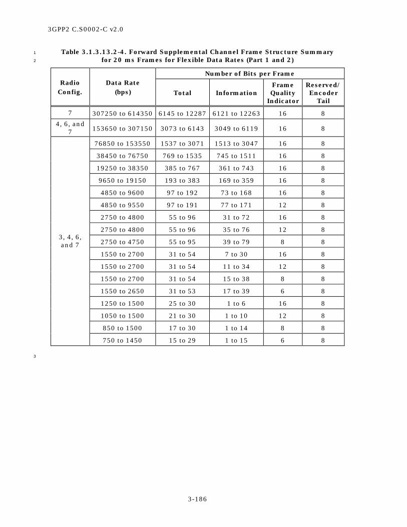
3GPP2 C.S0002-C v2.0
3-186
Table 3.1.3.13.2-4. Forward Supplemental Channel Frame Structure Summary 1
for 20 ms Frames for Flexible Data Rates (Part 1 and 2) 2
Number of Bits per Frame Radio
Config. Data Rate
(bps) Total Information Frame Quality
Indicator
Reserved/ Encoder
Tail
7 307250 to 614350 6145 to 12287 6121 to 12263 16 8
4, 6, and 7 153650 to 307150 3073 to 6143 3049 to 6119 16 8
76850 to 153550 1537 to 3071 1513 to 3047 16 8
38450 to 76750 769 to 1535 745 to 1511 16 8
19250 to 38350 385 to 767 361 to 743 16 8
9650 to 19150 193 to 383 169 to 359 16 8
4850 to 9600 97 to 192 73 to 168 16 8
4850 to 9550 97 to 191 77 to 171 12 8
2750 to 4800 55 to 96 31 to 72 16 8
2750 to 4800 55 to 96 35 to 76 12 8
2750 to 4750 55 to 95 39 to 79 8 8
1550 to 2700 31 to 54 7 to 30 16 8
1550 to 2700 31 to 54 11 to 34 12 8
1550 to 2700 31 to 54 15 to 38 8 8
1550 to 2650 31 to 53 17 to 39 6 8
1250 to 1500 25 to 30 1 to 6 16 8
1050 to 1500 21 to 30 1 to 10 12 8
850 to 1500 17 to 30 1 to 14 8 8
3, 4, 6, and 7
750 to 1450 15 to 29 1 to 15 6 8
3

3GPP2 C.S0002-C v2.0
3-187
Table 3.1.3.13.2-5. Forward Supplemental Channel Frame Structure Summary 1
for 20 ms Frames for Flexible Data Rates (Part 2 and 2) 2
Number of Bits per Frame Radio
Config. Data Rate
(bps) Total Information Frame Quality
Indicator
Reserved/ Encoder
Tail
9 460850 to 1036750 9217 to 20735 9193 to 20711 16 8
230450 to 460750 4609 to 9215 4585 to 9191 16 8 8 and 9
115250 to 230350 2305 to 4607 2281 to 4583 16 8
5 115250 to 230350 2305 to 4607 2281 to 4583 16 8
57650 to 115150 1153 to 2303 1129 to 2279 16 8
28850 to 57550 577 to 1151 553 to 1127 16 8
14450 to 28750 289 to 575 265 to 551 16 8
7250 to 14400 145 to 288 121 to 264 16 8
7250 to 14300, 14400
145 to 286, 288 125 to 266, 268 12 8
3650 to 7200 73 to 144 49 to 120 16 8
3650 to 7200 73 to 144 53 to 124 12 8
3650 to 7100, 7200 73 to 142, 144 55 to 124, 126 10 8
1850 to 3600 37 to 72 13 to 48 16 8
1850 to 3600 37 to 72 17 to 52 12 8
1850 to 3600 37 to 72 19 to 54 10 8
1850 to 3500, 3600 37 to 70, 72 21 to 54, 56 8 8
1250 to 1800 25 to 36 1 to 12 16 8
1050 to 1800 21 to 36 1 to 16 12 8
950 to 1800 19 to 36 1 to 18 10 8
850 to 1800 17 to 36 1 to 20 8 8
5, 8, and 9
750 to 1700, 1800 15 to 34, 36 1 to 20, 22 6 8
3

3GPP2 C.S0002-C v2.0
3-188
Table 3.1.3.13.2-6. Forward Supplemental Channel Frame Structure Summary 1
for 40 ms Frames for Flexible Data Rates (Part 1 of 2) 2
Number of Bits per Frame Radio
Config. Data Rate
(bps) Total Information Frame Quality
Indicator
Reserved/ Encoder
Tail
7 153625 to 307175 6145 to 12287 6121 to 12263 16 8
4, 6, and 7
76825 to 153575 3073 to 6143 3049 to 6119 16 8
38425 to 76775 1537 to 3071 1513 to 3047 16 8
19225 to 38375 769 to 1535 745 to 1511 16 8
9625 to 19175 385 to 767 361 to 743 16 8
4825 to 9575 193 to 383 169 to 359 16 8
2425 to 4800 97 to 192 73 to 168 16 8
2425 to 4775 97 to 191 77 to 171 12 8
1375 to 2400 55 to 96 31 to 72 16 8
1375 to 2400 55 to 96 35 to 76 12 8
1375 to 2375 55 to 95 39 to 79 8 8
775 to 1350 31 to 54 7 to 30 16 8
775 to 1350 31 to 54 11 to 34 12 8
775 to 1350 31 to 54 15 to 38 8 8
3, 4, 6, and 7
775 to 1325 31 to 53 17 to 39 6 8
3

3GPP2 C.S0002-C v2.0
3-189
Table 3.1.3.13.2-7. Forward Supplemental Channel Frame Structure Summary 1
for 40 ms Frames for Flexible Data Rates (Part 2 of 2) 2
Number of Bits per Frame Radio
Config. Data Rate
(bps) Total Information Frame Quality
Indicator
Reserved/ Encoder
Tail
9 230425 to 518375 9217 to 20735 9193 to 20711 16 8
115225 to 230375 4609 to 9215 4585 to 9191 16 8 8 and 9
57625 to 115175 2305 to 4607 2281 to 4583 16 8
5 57625 to 115175 2305 to 4607 2281 to 4583 16 8
28825 to 57575 1153 to 2303 1129 to 2279 16 8
14425 to 28775 577 to 1151 553 to 1127 16 8
7225 to 14375 289 to 575 265 to 551 16 8
3625 to 7200 145 to 288 121 to 264 16 8
3625 to 7150, 7200
145 to 286, 288
125 to 266, 268
12 8
1825 to 3600 73 to 144 49 to 120 16 8
1825 to 3600 73 to 144 53 to 124 12 8
1825 to 3550, 3600 73 to 142, 144 55 to 124, 126 10 8
925 to 1800 37 to 72 13 to 48 16 8
925 to 1800 37 to 72 17 to 52 12 8
925 to 1800 37 to 72 19 to 54 10 8
5, 8, and 9
925 to 1750, 1800 37 to 70, 72 21 to 54, 56 8 8
3

3GPP2 C.S0002-C v2.0
3-190
Table 3.1.3.13.2-8. Forward Supplemental Channel Frame Structure Summary 1
for 80 ms Frames for Flexible Data Rates (Part 1 of 2) 2
Number of Bits per Frame Radio
Config. Data Rate
(bps) Total Information Frame Quality
Indicator
Reserved/ Encoder
Tail
7 76812.5 to 153587.5 6145 to 12287 6121 to 12263 16 8
4, 6, and 7
38412.5 to 76787.5 3073 to 6143 3049 to 6119 16 8
19212.5 to 38387.5 1537 to 3071 1513 to 3047 16 8
9612.5 to 19187.5 769 to 1535 745 to 1511 16 8
4812.5 to 9587.5 385 to 767 361 to 743 16 8
2412.5 to 4787.5 193 to 383 169 to 359 16 8
1212.5 to 2400 97 to 192 73 to 168 16 8
1212.5 to 2387.5 97 to 191 77 to 171 12 8
687.5 to 1200 55 to 96 31 to 72 16 8
687.5 to 1200 55 to 96 35 to 76 12 8
3, 4, 6, and 7
687.5 to 1187.5 55 to 95 39 to 79 8 8
3

3GPP2 C.S0002-C v2.0
3-191
Table 3.1.3.13.2-9. Forward Supplemental Channel Frame Structure Summary 1
for 80 ms Frames for Flexible Data Rates (Part 2 of 2) 2
Number of Bits per Frame Radio
Config. Data Rate
(bps) Total Information Frame Quality
Indicator
Reserved/ Encoder
Tail
9 115212.5 to 259187.5 9217 to 20735
9193 to 20711
16 8
57612.5 to 115187.5 4609 to 9215 4585 to 9191 16 8
8 and 9 28812.5 to 57587.5 2305 to 4607 2281 to 4583 16 8
5 28812.5 to 57587.5 2305 to 4607 2281 to 4583 16 8
14412.5 to 28787.5 1153 to 2303 1129 to 2279 16 8
7212.5 to 14387.5 577 to 1151 553 to 1127 16 8
3612.5 to 7187.5 289 to 575 265 to 551 16 8
1812.5 to 3600 145 to 288 121 to 264 16 8
1812.5 to 3575, 3600 145 to 286, 288
125 to 266, 268
12 8
912.5 to 1800 73 to 144 49 to 120 16 8
912.5 to 1800 73 to 144 53 to 124 12 8
5, 8, and 9
912.5 to 1775, 1800 73 to 142, 144
55 to 124, 126
10 8
3

3GPP2 C.S0002-C v2.0
3-192
Information Bits F R/TR
Notation
R - Reserved BitF - Frame Quality Indicator (CRC)R/T - Reserved/Encoder Tail Bits
1
Figure 3.1.3.13.2-1. Forward Supplemental Channel Frame Structure 2
3
3.1.3.13.2.1 Forward Supplemental Channel Frame Quality Indicator 4
Each frame shall include a frame quality indicator. This frame quality indicator is a CRC. 5
The frame quality indicator (CRC) shall be calculated on all bits within the frame, except 6
the frame quality indicator itself and the Reserved/Encoder Tail Bits. 7
Frames in Radio Configurations 3, 4, 6, and 7 with more than 192 total bits shall use a 8
16-bit frame quality indicator. 9
Frames in Radio Configurations 5, 8, and 9 with more than 288 total bits shall use a 16-10
bit frame quality indicator. 11
Frames in Radio Configurations 3, 4, 6, and 7 with 97 to 192 total bits shall use a 12-bit 12
frame quality indicator. A 16-bit frame quality indicator may be used if flexible data rates 13
are supported. 14
Frames in Radio Configurations 5, 8, and 9 with 145 to 288 total bits shall use a 12-bit 15
frame quality indicator. A 16-bit frame quality indicator may be used if flexible data rates 16
are supported. 17
Frames in Radio Configurations 5, 8, and 9 with 73 to 144 total bits shall use a 10-bit 18
frame quality indicator. A 16-bit or 12-bit frame quality indicator may be used if flexible 19
data rates are supported. 20
Frames in Radio Configurations 3, 4, 6, and 7 with 55 to 96 total bits shall use an 8-bit 21
frame quality indicator. A 16-bit or 12-bit frame quality indicator may be used if flexible 22
data rates are supported. 23
Frames in Radio Configurations 5, 8, and 9 with 37 to 72 total bits shall use an 8-bit 24
frame quality indicator. A 16-bit, 12-bit, or 10-bit frame quality indicator may be used if 25
flexible data rates are supported. 26
Frames in Radio Configurations 3, 4, 6, and 7 with 54 or fewer total bits shall use a 6-bit 27
frame quality indicator. A 16-bit, 12-bit, or 8-bit frame quality indicator may be used if 28
flexible data rates are supported. 29
Frames in Radio Configurations 5, 8, and 9 with 36 or fewer total bits shall use a 6-bit 30
frame quality indicator. A 16-bit, 12-bit, 10-bit, or 8-bit frame quality indicator may be 31
used if flexible data rates are supported. 32

3GPP2 C.S0002-C v2.0
3-193
The generator polynomials for the frame quality indicator shall be as follows: 1
g(x) = x16 + x15 + x14 + x11 + x6 + x5 + x2 + x + 1 for the 16-bit frame quality indicator, 2
g(x) = x12 + x11 + x10 + x9 + x8 + x4 + x + 1 for the 12-bit frame quality indicator, 3
g(x) = x10 + x9 + x8 + x7 + x6 + x4 + x3 + 1 for the 10-bit frame quality indicator, 4
g(x) = x8 + x7 + x4 + x3 + x + 1 for the 8-bit frame quality indicator, and 5
g(x) = x6 + x5 + x2 + x + 1 for the 6-bit frame quality indicator. 6
The frame quality indicators shall be computed according to the following procedure as 7
shown in Figure 3.1.3.13.2.1-1 through Figure 3.1.3.13.2.1-5: 8
• Initially, all shift register elements shall be set to logical one and the switches shall 9
be set in the up position. 10
• The register shall be clocked a number of times equal to the number of reserved 11
and information bits in the frame with those bits as input. 12
• The switches shall be set in the down position so that the output is a modulo-2 13
addition with a ‘0’ and the successive shift register inputs are ‘0’s. 14
• The register shall be clocked an additional number of times equal to the number of 15
bits in the frame quality indicator (16, 12, 10, 8, or 6). 16
• These additional bits shall be the frame quality indicator bits. 17
• The bits shall be transmitted in the order calculated. 18
19
0
Input
0
Output
Denotes one-bit storage element
Denotes modulo-2 addition
Up for the information bits andthe reserved bitDown for the last 16 bits
x0 x6 x14x11 x15x1 x2 x5
20
Figure 3.1.3.13.2.1-1. Forward Supplemental Channel Frame Quality Indicator 21
Calculation for the 16-Bit Frame Quality Indicator 22
23
0
Input
0
Output
Denotes one-bit storage element
Denotes modulo-2 addition Up for the information bits and the reserved bit
Down for the last 12 bits
x0 x1 x4 x9x8 x10 x11
24
Figure 3.1.3.13.2.1-2. Forward Supplemental Channel Frame Quality Indicator 25
Calculation for the 12-Bit Frame Quality Indicator 26

3GPP2 C.S0002-C v2.0
3-194
1
0
Input
0
Output
Denotes one-bit storage element
Denotes modulo-2 addition
Up for the information bits and thereserved bitDown for the last 10 bits
x0 x1 x3 x7x5 x8 x9x2 x4 x6
2
Figure 3.1.3.13.2.1-3. Forward Supplemental Channel Frame Quality Indicator 3
Calculation for the 10-Bit Frame Quality Indicator 4
5
0
Input
0
Output
Denotes one-bit storage element
Denotes modulo-2 addition
Up for the information bits and the reserved bitDown for the last 8 bits
x0 x1 x2 x3 x4 x5 x6 x7
6
Figure 3.1.3.13.2.1-4. Forward Supplemental Channel Frame Quality Indicator 7
Calculation for the 8-Bit Frame Quality Indicator 8
9
0
Input
0
Output
Denotes one-bit storage element
Denotes modulo-2 addition Up for the information bits and the reserved bitDown for the last 6 bits
x0 x1 x2 x3 x4 x5
10
Figure 3.1.3.13.2.1-5. Forward Supplemental Channel Frame Quality Indicator 11
Calculation for the 6-Bit Frame Quality Indicator 12
13
3.1.3.13.2.2 Forward Supplemental Channel Encoder Tail Bits 14
The last eight bits of each Forward Supplemental Channel frame are called the 15
Reserved/Encoder Tail Bits. For the convolutional encoder, these eight bits shall each be 16

3GPP2 C.S0002-C v2.0
3-195
set to ‘0’. For the turbo encoder, the first two of the eight bits shall each be set to ‘0’, and 1
the turbo encoder will calculate and append the remaining six tail bits. 2
3.1.3.13.2.3 Forward Supplemental Channel Reserved Bit 3
This bit is reserved and shall be set to ‘0’. 4
3.1.3.13.3 Forward Supplemental Channel Forward Error Correction Encoding 5
The data for Forward Supplemental Channels shall be convolutionally or turbo encoded as 6
specified in 3.1.3.1.4. 7
3.1.3.13.4 Forward Supplemental Channel Code Symbol Repetition 8
Forward Supplemental Channel code symbol repetition shall be as specified in 3.1.3.1.5. 9
3.1.3.13.5 Forward Supplemental Channel Puncturing 10
Code symbols resulting from the symbol repetition shall be punctured as specified in 11
3.1.3.1.6. 12
3.1.3.13.6 Forward Supplemental Channel Interleaving 13
The modulation symbols shall be interleaved as specified in 3.1.3.1.7. 14
3.1.3.13.7 Forward Supplemental Channel Data Scrambling 15
The data for Forward Supplemental Channels shall be scrambled as specified in 3.1.3.1.9. 16
The same long code mask is used for all code channels of the Forward Traffic Channel. The 17
public long code mask shall be specified by PLCM_42 (see 2.3.6 in [5]) The public long 18
code mask shall be as shown in Figure 3.1.3.13.7-1. The generation of the private long 19
code mask shall be as specified in 2.1.3.1.12. 20
21
11000 PLCM_37
41 … 37 36 … 0
22
Figure 3.1.3.13.7-1. Forward Supplemental Channel Public Long Code Mask 23
24
3.1.3.13.8 Forward Supplemental Channel Orthogonal and Quasi-Orthogonal Spreading 25
The Forward Supplemental Channels shall be spread by a Walsh function or quasi-26
orthogonal function as specified in 3.1.3.1.150. 27
3.1.3.13.9 Forward Supplemental Channel Quadrature Spreading 28
The Forward Supplemental Channels shall be PN spread as specified in 3.1.3.1.16. 29

3GPP2 C.S0002-C v2.0
3-196
3.1.3.13.10 Forward Supplemental Channel Filtering 1
Filtering for tThe Forward Supplemental Channels shall be filtered as specified in 2
3.1.3.1.17. 3
3.1.3.13.11 Forward Supplemental Channel Transmission Processing 4
When the Physical Layer receives a PHY-SCH.Request(SDU, FRAME_DURATION, 5
NUM_BITS) from the MAC Layer, the base station shall perform the following: 6
• Store the arguments SDU, FRAME_DURATION, and NUM_BITS. 7
• If SDU is not equal to NULL, set the information bits to SDU. 8
• If SDU is not equal to NULL, transmit NUM_BITS bits of SDU in a Forward 9
Supplemental Channel frame of duration FRAME_DURATION. 10
3.1.3.14 Forward Supplemental Code Channel 11
The Forward Supplemental Code Channel applies to Radio Configurations 1 and 2 only. 12
The Forward Supplemental Code Channel is used for the transmission of user 13
informationhigher-level data to a specific mobile station during a call. Each Forward 14
Traffic Channel contains up to seven Forward Supplemental Code Channels. 15
3.1.3.14.1 Forward Supplemental Code Channel Time Alignment and Modulation Rates 16
When transmitting on Forward Supplemental Code Channels with Radio Configuration 1, 17
the base station shall transmit information at 9600 bps. When transmitting on Forward 18
Supplemental Code Channels with Radio Configuration 2, the base station shall transmit 19
information at 14400 bps. 20
All Forward Supplemental Code Channel frames shall be 20 ms in duration. 21
For a given base station, the I and Q channel pilot PN sequences for the Forward 22
Supplemental Code Channels shall use the same pilot PN sequence offset as for the 23
Forward Pilot Channel. 24
The base station may support Forward Supplemental Code Channel frames that are time 25
offset by multiples of 1.25 ms. The amount of the time offset is specified by 26
FRAME_OFFSET. A zero-offset Forward Supplemental Code Channel frame shall begin 27
only when System Time is an integral multiple of 20 ms (see Figure 1.3-1). An offset 28
Forward Supplemental Code Channel frame shall begin 1.25 × FRAME_OFFSET ms later 29
than the zero-offset Forward Supplemental Code Channel frame. The base station shall 30
transmit frames on the Forward Supplemental Code Channels in time alignment with the 31
Forward Fundamental Channel. The interleave block for the Forward Supplemental Code 32
Channel shall be aligned with the Forward Supplemental Code Channel frame. 33
3.1.3.14.2 Forward Supplemental Code Channel Frame Structure 34
Table 3.1.3.14.2-1 specifies the Forward Supplemental Code Channel bit allocations. All 35
frames shall consist of zero or one Reserved Bits and information bits followed by a frame 36
quality indicator (CRC) and eight Encoder Tail Bits, as shown in Figure 3.1.3.14.2-1. 37

3GPP2 C.S0002-C v2.0
3-197
1
Table 3.1.3.14.2-1. Forward Supplemental Code Channel Frame Structure Summary 2
Number of Bits per Frame Radio
Config. Data Rate
(bps) Total Reserved Informa-
tion Frame Quality
Indicator Encoder
Tail
1 9600 192 0 172 12 8
2 14400 288 1 267 12 8
3
Information Bits F TR
Notation
R - Reserved BitF - Frame Quality Indicator (CRC)T - Encoder Tail Bits
4
Figure 3.1.3.14.2-1. Forward Supplemental Code Channel Frame Structure 5
6
3.1.3.14.2.1 Forward Supplemental Code Channel Frame Quality Indicator 7
The frame quality indicator (CRC) shall be calculated on all bits within the frame, except 8
the frame quality indicator itself and the Encoder Tail Bits. Each frame with Radio 9
Configuration 1 and 2 shall include a 12-bit frame quality indicator. This frame quality 10
indicator is a CRC. 11
The generator polynomial for the frame quality indicator shall be as follows: 12
g(x) = x12 + x11 + x10 + x9 + x8 + x4 + x + 1. 13
The frame quality indicators shall be computed according to the following procedure as 14
shown in Figure 3.1.3.14.2.1-1: 15
• Initially, all shift register elements shall be set to logical one and the switches shall 16
be set in the up position. 17
• The register shall be clocked a number of times equal to the number of reserved 18
and information bits in the frame with those bits as input. 19
• The switches shall be set in the down position so that the output is a modulo-2 20
addition with a ‘0’ and the successive shift register inputs are ‘0’s. 21
• The register shall be clocked an additional number of times equal to the number of 22
bits in the frame quality indicator (12). 23
• These additional bits shall be the frame quality indicator bits. 24
• The bits shall be transmitted in the order calculated. 25

3GPP2 C.S0002-C v2.0
3-198
1
0
Input
0
Output
Denotes one-bit storage element
Denotes modulo-2 addition
Up for the first 172 bits for the 9600 bps rateand for the first 268 bits for the 14400 rateDown for the last 12 bits
x0 x1 x4 x9x8 x10 x11
2
Figure 3.1.3.14.2.1-1. Forward Supplemental Code Channel Frame Quality Indicator 3
Calculation 4
5
3.1.3.14.2.2 Forward Supplemental Code Channel Encoder Tail Bits 6
The last eight bits of each Forward Supplemental Code Channel frame are called the 7
Reserved/Encoder Tail Bits. These eight bits shall each be set to ‘0’. 8
3.1.3.14.2.3 Forward Supplemental Code Channel Reserved Bit 9
This bit is reserved and shall be set to ‘0’. 10
3.1.3.14.3 Forward Supplemental Code Channel Convolutional Encoding 11
The data for Forward Supplemental Code Channels shall be convolutionally encoded as 12
specified in 3.1.3.1.4. 13
When generating Forward Supplemental Code Channel data, the encoder shall be 14
initialized to the all-zero state at the end of each 20 ms frame. 15
3.1.3.14.4 Forward Supplemental Code Channel Code Symbol Repetition 16
Forward Supplemental Code Channel code symbol repetition shall be as specified in 17
3.1.3.1.5. 18
3.1.3.14.5 Forward Supplemental Code Channel Puncturing 19
Code symbols resulting from the symbol repetition shall be punctured as specified in 20
3.1.3.1.6. 21
3.1.3.14.6 Forward Supplemental Code Channel Interleaving 22
The modulation symbols shall be interleaved as specified in 3.1.3.1.7. 23
3.1.3.14.7 Forward Supplemental Code Channel Data Scrambling 24
The data for Forward Supplemental Code Channels shall be scrambled as specified in 25
3.1.3.1.9. The same long code mask is used for all code channels of the Forward Traffic 26
Channel. The public long code mask shall be specified by PLCM_42 (see 2.3.6 in [5]) The 27
public long code mask shall be as shown in Figure 3.1.3.14.7-1. The generation of the 28
private long code mask shall be as specified in 2.1.3.1.11. 29

3GPP2 C.S0002-C v2.0
3-199
1
11000 PLCM_37
41 … 37 36 … 0
2
Figure 3.1.3.14.7-1. Forward Supplemental Code Channel Public Long Code Mask 3
4
3.1.3.14.8 Forward Supplemental Code Channel Orthogonal Spreading 5
The Forward Supplemental Code Channels shall be spread by a Walsh function of length 6
64 as specified in 3.1.3.1.150. 7
3.1.3.14.9 Forward Supplemental Code Channel Quadrature Spreading 8
The Forward Supplemental Code Channels shall be PN spread as specified in 3.1.3.1.16. 9
3.1.3.14.10 Forward Supplemental Code Channel Filtering 10
Filtering for tThe Forward Supplemental Code Channels shall be filtered as specified in 11
3.1.3.1.17. 12
3.1.3.14.11 Forward Supplemental Code Channel Transmission Processing 13
When the Physical Layer receives a PHY-SCCH.Request(SDU, FRAME_DURATION, 14
NUM_BITS) from the MAC Layer, the base station shall perform the following: 15
• Store the arguments SDU, FRAME_DURATION, and NUM_BITS. 16
• If SDU is not equal to NULL, set the information bits to SDU. 17
• If SDU is not equal to NULL, transmit NUM_BITS bits of SDU in a Forward 18
Supplemental Code Channel frame. 19
3.1.3.15 Forward Packet Data Channel 20
The Forward Packet Data Channel is used for the transmission of user informationhigher-21
level data to the mobile stations with Spreading Rate 1. A forward CDMA channel may 22
contain up to two Forward Packet Data Channels. Each Forward Packet Data Channel 23
transmits information to one specific mobile station at a time. 24
3.1.3.15.1 Forward Packet Data Channel Structure, Time Alignment, and Subpacket Data 25
Rates 26
The Forward Packet Data Channel shall transmit 386, 770, 1538, 2306, 3074, or 3842 27
information bits. Sixteen packet frame quality indicator bits and six turbo encoder tail 28
allowance bits shall be added to the information bits to form encoder packets. The encoder 29
packets shall be encoded with a rate-1/5 turbo encoder, interleaved, and scrambled. 30
Then, symbols from the scrambled sequence shall be selected for transmission as a 31
subpacket. The selected symbols may not include all of the scrambled output symbols or 32
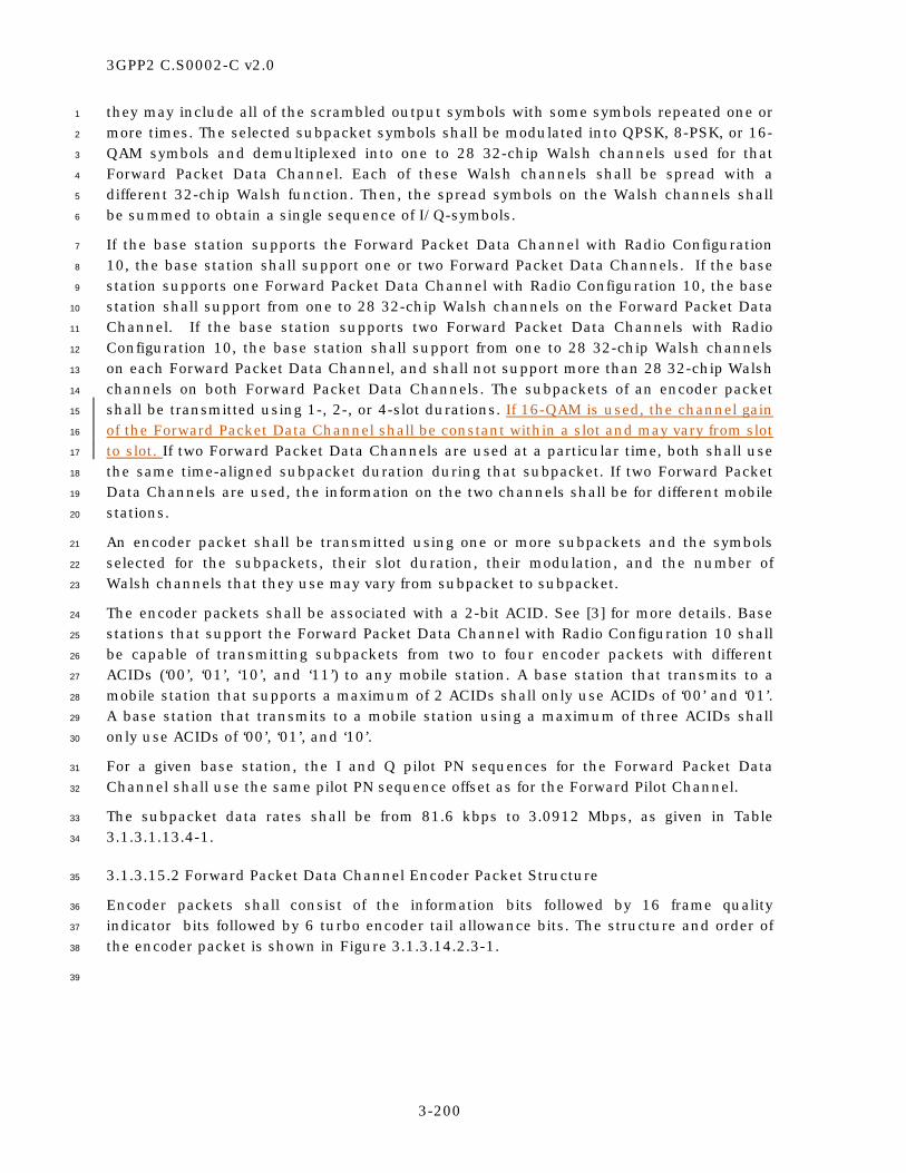
3GPP2 C.S0002-C v2.0
3-200
they may include all of the scrambled output symbols with some symbols repeated one or 1
more times. The selected subpacket symbols shall be modulated into QPSK, 8-PSK, or 16-2
QAM symbols and demultiplexed into one to 28 32-chip Walsh channels used for that 3
Forward Packet Data Channel. Each of these Walsh channels shall be spread with a 4
different 32-chip Walsh function. Then, the spread symbols on the Walsh channels shall 5
be summed to obtain a single sequence of I/Q-symbols. 6
If the base station supports the Forward Packet Data Channel with Radio Configuration 7
10, the base station shall support one or two Forward Packet Data Channels. If the base 8
station supports one Forward Packet Data Channel with Radio Configuration 10, the base 9
station shall support from one to 28 32-chip Walsh channels on the Forward Packet Data 10
Channel. If the base station supports two Forward Packet Data Channels with Radio 11
Configuration 10, the base station shall support from one to 28 32-chip Walsh channels 12
on each Forward Packet Data Channel, and shall not support more than 28 32-chip Walsh 13
channels on both Forward Packet Data Channels. The subpackets of an encoder packet 14
shall be transmitted using 1-, 2-, or 4-slot durations. If 16-QAM is used, the channel gain 15
of the Forward Packet Data Channel shall be constant within a slot and may vary from slot 16
to slot. If two Forward Packet Data Channels are used at a particular time, both shall use 17
the same time-aligned subpacket duration during that subpacket. If two Forward Packet 18
Data Channels are used, the information on the two channels shall be for different mobile 19
stations. 20
An encoder packet shall be transmitted using one or more subpackets and the symbols 21
selected for the subpackets, their slot duration, their modulation, and the number of 22
Walsh channels that they use may vary from subpacket to subpacket. 23
The encoder packets shall be associated with a 2-bit ACID. See [3] for more details. Base 24
stations that support the Forward Packet Data Channel with Radio Configuration 10 shall 25
be capable of transmitting subpackets from two to four encoder packets with different 26
ACIDs (‘00’, ‘01’, ‘10’, and ‘11’) to any mobile station. A base station that transmits to a 27
mobile station that supports a maximum of 2 ACIDs shall only use ACIDs of ‘00’ and ‘01’. 28
A base station that transmits to a mobile station using a maximum of three ACIDs shall 29
only use ACIDs of ‘00’, ‘01’, and ‘10’. 30
For a given base station, the I and Q pilot PN sequences for the Forward Packet Data 31
Channel shall use the same pilot PN sequence offset as for the Forward Pilot Channel. 32
The subpacket data rates shall be from 81.6 kbps to 3.0912 Mbps, as given in Table 33
3.1.3.1.13.4-1. 34
3.1.3.15.2 Forward Packet Data Channel Encoder Packet Structure 35
Encoder packets shall consist of the information bits followed by 16 frame quality 36
indicator bits followed by 6 turbo encoder tail allowance bits. The structure and order of 37
the encoder packet is shown in Figure 3.1.3.14.2.3-1. 38
39

3GPP2 C.S0002-C v2.0
3-201
Information Bits386, 770, 1538, 2306, 3074, or 3842 Bits
FrameQuality
Indicator(16 Bits)
TurboEncoder Tail
Allowance(6 Bits)
1
Figure 3.1.3.14.2.3-1. Forward Packet Data Channel Encoder Packet Structure 2
3
3.1.3.15.2.1 Forward Packet Data Channel Packet Frame Quality Indicator 4
The frame quality indicator shall be calculated based on the input information bits. A 16-5
bit frame quality indicator shall be used. The generator polynomial for the frame quality 6
indicator shall be 7
g(x) = x16 + x15 + x14 + x11 + x6 + x5 + x2 + x + 1. 8
The frame quality indicator shall be computed according to the following procedure as 9
shown in Figure 3.1.3.15.2.1-1: 10
• Initially, all shift register elements shall be set to logical one and the switches shall 11
be set in the up position. 12
• The register shall be clocked a number of times equal to the number of information 13
bits with those bits as input. 14
• The switches shall be set in the down position so that the output is a modulo-2 15
addition with a ‘0’ and the successive shift register inputs are ‘0’s. 16
• The register shall be clocked an additional 16 times. 17
• These additional bits shall be the frame quality indicator bits. 18
• The bits shall be transmitted in the order calculated. 19
20
0
Input
0
Output
Denotes one-bit storage element
Denotes modulo-2 addition
x0 x6 x14x11 x15x1 x2 x5
Up for the information bitsDown for the last 16 bits.
21
Figure 3.1.3.15.2.1-1. Forward Packet Data Channel Frame Quality Indicator 22
23
3.1.3.15.2.2 Forward Packet Data Channel Turbo Encoder Tail Allowance 24
Encoder packets include a 6-bit turbo encoder tail allowance, as described in 3.1.3.15.2. 25
The turbo encoder discards the turbo encoder tail allowance bits and adds turbo encoder 26
output tail bits such that the number of bits out of the rate-1/5 turbo encoder is five 27
times the number of bits in an encoder packet. 28

3GPP2 C.S0002-C v2.0
3-202
3.1.3.15.3 Forward Packet Data Channel Turbo Encoding 1
Encoder packets shall be turbo encoded with a code rate of 1/5 as specified in 3.1.3.1.4.2. 2
3.1.3.15.4 Forward Packet Data Channel Interleaving 3
The turbo encoder output sequence shall be interleaved as specified in 3.1.3.1.7.1.3. 4
3.1.3.15.5 Forward Packet Data Channel Packet Data Scrambling 5
The interleaved sequence shall be covered with a scrambler sequence as specified in 6
3.1.3.1.10. The public long code mask shall be specified by PLCM_42 (see 2.3.6 in [5]) The 7
public long code mask shall be as shown in Figure 3.1.3.15.5-1. The generation of the 8
private long code mask shall be as specified in 2.1.3.1.12. 9
10
11000 PLCM_37
41 … 37 36 … 0
11
Figure 3.1.3.15.5-1. Forward Packet Data Channel Public Long Code Mask 12
13
3.1.3.15.6 Forward Packet Data Channel Subpacket Symbol Selection 14
Subpacket symbols are selected from the scrambler output sequence as specified in 15
3.1.3.1.12. 16
3.1.3.15.7 Forward Packet Data Channel Modulation 17
The symbols from the subpacket symbol selection process shall be modulated as specified 18
in 3.1.3.1.13. 19
3.1.3.15.8 Forward Packet Data Channel Walsh Channel Processing 20
The modulated symbols shall be demultiplexed into Walsh channels, each Walsh channel 21
shall be Walsh spread, and the spread symbols from the Walsh channels shall be summed 22
as specified in 3.1.3.1.14.4. 23
3.1.3.15.9 Forward Packet Data Channel Quadrature Spreading 24
The Forward Packet Data Channel shall be PN spread as specified in 3.1.3.1.16. 25
3.1.3.15.10 Forward Packet Data Channel Filtering 26
Filtering for tThe Forward Packet Data Channel shall be filtered as specified in 3.1.3.1.17. 27
3.1.3.15.11 Forward Packet Data Channel Transmission Processing 28
When the Physical Layer receives a PHY-FPDCH.Request(EP, SPID, NUM_SLOTS, 29
WCI_SET, SYS_TIME) from the MAC Layer, the base station shall: 30

3GPP2 C.S0002-C v2.0
3-203
• Store the arguments EP, SPID, NUM_SLOTS, WCI_SET, and SYS_TIME. 1
• Use the EP, and SPID as information to form an encoder packet as specified in 2
3.1.3.1.12 with duration NUM_SLOTS. The Physical Layer shall use the Walsh 3
cCodes corresponding to the Walsh cCode indices specified in WCI_SET to encode 4
the encoder packet. 5
• Transmit the encoder packet on the Forward Packet Data Channel frame at 6
SYS_TIME with duration NUM_SLOTS. 7
3.1.4 Limitations on Emissions 8
3.1.4.1 Conducted Spurious Emissions 9
The base station shall meet the requirements in Section 4.45.1 of the current version of 10
[10]. 11
3.1.4.2 Radiated Spurious Emissions 12
The base station shall meet the requirements in Section 4.45.2 of the current version of 13
[10]. 14
3.1.4.3 Intermodulation Products 15
The base station shall meet the requirements in Section 4.4.3 of the current version of 16
[10]. 17
3.1.5 Synchronization, Timing, and Phase 18
3.1.5.1 Timing Reference Source 19
Each base station shall use a time base reference from which all time-critical CDMA 20
transmission components, including pilot PN sequences, frames, and Walsh functions, 21
shall be derived. The time base reference shall be time-aligned to CDMA System Time, as 22
described in 1.3. Reliable external means should be provided at each base station to 23
synchronize each base station’s time base reference to CDMA System Time. Each base 24
station should use a frequency reference of sufficient accuracy to maintain time alignment 25
to CDMA System Time. 26

3GPP2 C.S0002-C v2.0
3-204
In the event that the external source of System Time is lost,29 the system shall maintain 1
the base station transmit time within the tolerance specified in 3.1.5.2 for a period of time 2
specified in the current version of [10]. 3
3.1.5.2 Base Station Transmission Time 4
The base station shall meet the requirements in Section 4.23.1.1 of the current version of 5
[10]. 6
Time measurements are made at the base station antenna connector. If a base station has 7
multiple radiating antenna connectors for the same CDMA channel, time measurements 8
are made at the antenna connector having the earliest radiated signal. 9
The rate of change for timing corrections shall not exceed 101.725 ns per 200 ms. 10
3.1.5.3 Pilot to Walsh Cover Time Tolerance 11
The base station shall meet the requirements in Section 4.23.1.2 of the current version of 12
[10]. 13
3.1.5.4 Pilot to Walsh Cover Phase Tolerance 14
The base station shall meet the requirements in Section 4.23.1.3 of the current version of 15
[10]. 16
3.1.6 Transmitter Performance Requirements 17
System performance is predicated on transmitters meeting the requirements set forth in 18
the current version of [10]. 19
3.2 Receiver 20
3.2.1 Channel Spacing and Designation 21
Channel spacing and designations for the base station reception shall be as specified in 22
2.1.1.1. 23
29These guidelines on time keeping requirements reflect the fact that the amount of time error
between base stations that can be tolerated in a CDMA network is not a hard limit. Each mobile
station can search an ever increasing time window as directed by the base stations. However,
increasing this window gradually degrades performance, since wider windows require a longer time
for the mobile stations to search out and to locate the various arrivals from all base stations that
may be in view. An eventual limit on time errors occurs, since pilot addresses are derived as 64 chip
time shifts of a length 32768 chip sequence. In a very extreme case where the maximum number of
512 sequences were assigned to base stations, these address sequences would be 64 chips apart. In
this situation, it is possible that large time errors between base station transmissions would be
confused with path-delayed arrivals from a given base station.

3GPP2 C.S0002-C v2.0
3-205
3.2.2 Demodulation Characteristics 1
The base station demodulation process shall perform complementary operations to the 2
mobile station modulation process on the Reverse CDMA Channel (see 2.1.3). 3
The base station receiver shall support the operation of the rReverse pPower cControl 4
sSubchannel as specified in 3.1.3.1.11. 5
The Reverse Traffic Channel frame is described in 2.1.3.6.2, 2.1.3.9.2, 2.1.3.10.2, and 6
2.1.3.11.2. A base station may implement offset Reverse Traffic Channel frames as 7
described in 2.1.3.6.1, 2.1.3.9.1, 2.1.3.10.1, and 2.1.3.11.1. 8
3.2.2.1 Interface to the MAC Layer 9
This section specifies the passing of the received physical layer frames. 10
3.2.2.1.1 Reverse Pilot Channel Reception Processing 11
If PILOT_GATING_USE_RATEs = 1, the base station shall monitor the Reverse Pilot 12
Channel and continue monitoring the Reverse Fundamental Channel and/or the Reverse 13
Dedicated Control Channel if they existed in active mode. If the base station detects the 14
continuous Reverse Pilot or a valid frame for the Reverse Fundamental Channel or 15
Reverse Dedicated Control Channel, the Physical Layer shall send a CONTINUOUS-16
REVERSE-PILOT.Indication to the MAC Layer. 17
3.2.2.1.13.2.2.1.2 Access Channel Reception Processing 18
When the base station receives an Access Channel frame, the Physical Layer shall send a 19
PHY-ACH.Indication(SDU, FRAME_QUALITY) to the MAC Layer, after the base station 20
performs the following actions: 21
• Set the SDU to the received information bits. 22
• Set FRAME_QUALITY to “sufficient” if the received frame has sufficient frame 23
quality; otherwise, set FRAME_QUALITY to “insufficient.” 24
3.2.2.1.23.2.2.1.3 Enhanced Access Channel Reception Processing 25
When the base station receives an Enhanced Access Channel Preamble, the Physical 26
Layer shall send a PHY-EACHPreamble.Indication to the MAC Layer. 27
When the base station receives an Enhanced Access header, the Physical Layer shall send 28
a PHY-EACHHeader.Indication(SDU, FRAME_QUALITY) to the MAC Layer, after the base 29
station performs the following actions: 30
• Set SDU to the received information bits. 31
• Set FRAME_QUALITY to “sufficient” if the received frame has sufficient frame 32
quality; otherwise, set FRAME_QUALITY to “insufficient.” 33
When the base station receives an Enhanced Access data frame, the Physical Layer shall 34
send a PHY-EACH.Indication(SDU, FRAME_DURATION, NUM_BITS, FRAME_QUALITY) to 35
the MAC Layer, after the base station performs the following actions: 36
• Set SDU to the received information bits. 37

3GPP2 C.S0002-C v2.0
3-206
• Set FRAME_DURATION to the duration of the received frame. 1
• Set NUM_BITS to the number of data bits of the received frame. 2
• Set FRAME_QUALITY to “sufficient” if the received frame has sufficient frame 3
quality; otherwise, set FRAME_QUALITY to “insufficient.” 4
3.2.2.1.33.2.2.1.4 Reverse Common Control Channel Reception Processing 5
When the base station receives a Reverse Common Control Channel preamble, the 6
Physical Layer shall send a PHY-RCCCHPreamble.Indication to the MAC Layer. 7
When the base station receives a Reverse Common Control Channel frame, the Physical 8
Layer shall send a PHY-RCCCH.Indication(SDU, FRAME_DURATION, NUM_BITS, 9
FRAME_QUALITY) to the MAC Layer, after the base station performs the following actions: 10
• Set SDU to the received information bits. 11
• Set FRAME_DURATION to the duration of the received frame. 12
• Set NUM_BITS to the number of data bits of the received frame. 13
• Set FRAME_QUALITY to “sufficient” if the received frame has sufficient frame 14
quality; otherwise, set FRAME_QUALITY to “insufficient.” 15
3.2.2.1.43.2.2.1.5 Reverse Dedicated Control Channel Reception Processing 16
When the base station receives a Reverse Dedicated Control Channel frame, the Physical 17
Layer shall send a PHY-DCCH.Indication(SDU, FRAME_DURATION, NUM_BITS, 18
FRAME_QUALITY) to the MAC Layer, after the base station performs the following actions: 19
• Set the SDU to the received information bits. 20
• Set FRAME_DURATION to the duration of the received frame. 21
• Set NUM_BITS to the number of information bits in the SDU. 22
• Set FRAME_QUALITY to “sufficient” if the received frame has sufficient frame 23
quality; otherwise, set FRAME_QUALITY to “insufficient.” 24
If the base station does not receive a ReverseForward Dedicated Control Channel frame at 25
the end of a 20 ms frame boundary, the Physical Layer shall send a PHY-26
DCCH.Indication(SDU) to the MAC Layer, after the base station performs the following 27
actions: 28
• Set the SDU to NULL. 29
• Pass the SDU as an argument. 30
3.2.2.1.53.2.2.1.6 Reverse Acknowledgment Channel Reception Processing 31
When the base station receives a Reverse Acknowledgment Channel frame, the Physical 32
Layer shall send a PHY-RACKCH.Indication(ACK_OR_NAK) to the MAC Layer, after the 33
base station performs the following actions: 34

3GPP2 C.S0002-C v2.0
3-207
• Set ACK_OR_NAK to NAK if a NAK was received on the Reverse Acknowledgment 1
Channel and to ACK if an ACK was received on the Reverse Acknowledgment 2
Channel. 3
3.2.2.1.63.2.2.1.7 Reverse Channel Quality Indicator Channel Reception Processing 4
When the base station receives a Reverse Channel Quality Indicator Channel frame, the 5
Physical Layer shall send a PHY-RCQICH.Indication(CQI_VALUE, WALSH_COVER) to the 6
MAC Layer after the base station performs the following action: 7
• Set the CQI_VALUE to the received channel quality indicator value. 8
• Set the WALSH_COVER to the 3-bit value corresponding to the 8-ary Walsh 9
function received on the Reverse Chjannel Quality Indicator Channel as specified 10
in Table 2.1.3.8.1-1. 11
3.2.2.1.73.2.2.1.8 Reverse Fundamental Channel Reception Processing 12
When the base station receives a Reverse Fundamental Channel frame, the Physical Layer 13
shall send a PHY-FCH.Indication(SDU, FRAME_DURATION, NUM_BITS, FRAME_QUALITY) 14
to the MAC Layer, after the base station performs the following actions: 15
• Set the SDU to the received information bits. 16
• Set FRAME_DURATION to the duration of the received frame. 17
• Set NUM_BITS to the number of bits of the SDU. 18
• Set FRAME_QUALITY to “sufficient” if the received frame has sufficient frame 19
quality; otherwise, set FRAME_QUALITY to “insufficient.” 20
3.2.2.1.8Reverse Pilot Channel Reception Processing 21
If PILOT_GATING_USE_RATEs = 1, the base station shall monitor the Reverse Pilot 22
Channel and continue monitoring the Reverse Fundamental Channel and/or the Reverse 23
Dedicated Control Channel if they existed in active mode. If the base station detects the 24
continuous Reverse Pilot or a valid frame for the Reverse Fundamental Channel or 25
Reverse Dedicated Control Channel, the Physical Layer shall send a CONTINUOUS-26
REVERSE-PILOT.Indication to the MAC Layer. 27
3.2.2.1.9 Reverse Supplemental Channel Reception Processing 28
When the base station receives a Reverse Supplemental Channel frame, the Physical Layer 29
shall send a PHY-SCH.Indication(SDU, FRAME_DURATION, NUM_BITS, FRAME_QUALITY) 30
to the MAC Layer, after the base station performs the following actions: 31
• Set the SDU to the received information bits. 32
• Set FRAME_DURATION to the duration of the received frame. 33
• Set NUM_BITS to the number of bits of the SDU. 34
• Set FRAME_QUALITY to “sufficient” if the received frame has sufficient frame 35
quality; otherwise, set FRAME_QUALITY to “insufficient.” 36

3GPP2 C.S0002-C v2.0
3-208
3.2.2.1.10 Reverse Supplemental Code Channel Reception Processing 1
When the base station receives a Reverse Supplemental Code Channel frame, the Physical 2
Layer shall send a PHY-SCCH.Indication(SDU, FRAME_DURATION, NUM_BITS, 3
FRAME_QUALITY) to the MAC Layer, after the base station performs the following actions: 4
• Set the SDU to the received information bits. 5
• Set FRAME_DURATION to the duration of the received frame. 6
• Set NUM_BITS to the number of bits of the SDU. 7
• Set FRAME_QUALITY to “sufficient” if the received frame has sufficient frame 8
quality; otherwise, set FRAME_QUALITY to “insufficient.” 9
3.2.3 Limitations on Emissions 10
The base station shall meet the requirements in Section 3.65.1 of the current version of 11
[10]. 12
3.2.4 Receiver Performance Requirements 13
System performance is predicated on receivers meeting the requirements set forth in the 14
current version of [10]. 15
16
17
18