Embed Size (px)
Citation preview

Ares I-X
National Aeronautics and Space Administration
PRESS KITOCTOBER 2009
www.nasa.gov
OVERVIEW .................................................................................................................................... 3 LAUNCH VEHICLE DATA ............................................................................................................. 4
FLIGHT TEST OBJECTIVES ........................................................................................................ 5
FLIGHT TEST PROFILE ............................................................................................................... 6
VEHICLE FIRST STAGE ........................................................................................... ............ 8 UPPER STAGE SIMULATOR ................................................................................ 14 ROLL CONTROL SYSTEM ................................................................................... 17 CREW MODULE AND LAUNCH ABORT SYSTEM ............................................. 19 AVIONICS .............................................................................................................. 20
SYSTEMS ENGINEERING AND INTEGRATION ......................................................................... 22
LAUNCH COMMIT CRITERIA ...................................................................................................... 23
WEATHER CONSTRAINTS .......................................................................................................... 24
PARTNERS ................................................................................................................................... 25
GROUND OPERATIONS AND GROUND SYSTEMS ................................................................... 26 LAUNCH PAD 39B ............................................................................................................ 27 MOBILE LAUNCHER PLATFORM ................................................................................... 28 CRAWLER-TRANSPORTER ............................................................................................ 30 CRAWLERWAY ................................................................................................................ 31 YOUNG-CRIPPEN FIRING ROOM ................................................................................... 32 LAUNCH TEAM ................................................................................................................. 33 COUNTDOWN SUMMARY ................................................................................................ 36
TRANSITION TO CONSTELLATION OVERVIEW ........................................................................................................................ 40 ORION CREW EXPLORATION VEHICLE ........................................................................ 41 ARES I CREW LAUNCH VEHICLE .................................................................................. 42
ACRONYMS .................................................................................................................................. 43 PUBLIC AFFAIRS CONTACTS .................................................................................................... 45
ADDITIONAL INFORMATION ....................................................................................................... 46
CONTENTSSection Page
Ares I-XPRESS KIT

The first flight test for NASA’s Constellation Program is called Ares I-X and it will bring the agency one step closer to its exploration goals -- to transport astronauts to the International Space Station after the space shuttle retires and explore destinations beyond low Earth orbit.
The flight of the Ares I-X rocket will provide NASA an early opportunity to test and prove hardware, models, facilities and ground operations associated with the Ares I launch vehicle.
The flight also will allow NASA to gather critical data during ascent of the integrated stack, which includes the Ares I launch vehicle with a simulated upper stage, Orion crew exploration vehicle and launch abort system. Data collected, including from more than 700 sensors throughout the rocket, will begin to confirm the vehicle as a whole is safe and stable in flight before astronauts begin traveling into orbit.
OVERVIEW
OCTOBER 2009 3
Ares I-XPRESS KIT
The Ares I-X rocket sits on Launch Pad 39B awaiting its targeted Oct. 27, 2009, liftoff from NASA’s Kennedy Space Center.

Vehicle: Ares I-X
Launch Site: Kennedy Space Center
Launch Pad: 39B
Launch Date: Oct. 27, 2009
Launch Time: 8 a.m. EDT
Launch Window: Four hours (approximately)
Separation Altitude: 130,000 feet, 24.6 miles
Maximum Altitude: 150,000 feet, 28.4 miles
Maximum Mach: 4.76
Maximum Acceleration: 2.48 g
Maximum Thrust: 3.3 million pounds
Flight Path: East (28.5 degrees inclination)
Powered Flight Duration: 124 seconds
Total Flight Duration: 369 seconds
Liftoff Weight: 1.8 million pounds
Vehicle Height: 327.24 feet
OCTOBER 2009 4
Ares I-XPRESS KIT
LAUNCH VEHICLE DATA

The purpose of a development flight test is to combine direct observation, experience and physical measurements with modeling analysis, which leads to a deeper understanding and insight of the vehicle.
• Validate the initial vehicle design • Gain practical experience with the vehicle • Learn as much as possible, as early as possible in the product development cycle • Testing is vital in developing and designing new vehicles
Objectives
• Demonstrate controllability of new launch vehicle dynamically similar to Ares I
• Assembly and recovery of new launch vehicle
• Demonstrate parachute performance and booster entry sequence
• Characterize in-flight roll characteristics
• Perform stage separation of new launch vehicle
The goal of a development flight test is to:
Gather information to improve analysis capability and design activities for future rockets
Success Criteria
• Successful rollout to launch pad
• Rocket safely clears the launch pad
• Rocket remains within the determined flight profile
• Collect flight data that can be used to improve the design of future launch vehicles
FLIGHT TEST OBJECTIVES
OCTOBER 2009 5
Ares I-XPRESS KIT

FLIGHT TEST PROFILE
OCTOBER 2009 6
Ares I-XPRESS KIT
The Ares I-X rocket will be similar in mass and size to the actual Ares I rocket and Orion spacecraft systems, but it will incorporate a mix of proven spaceflight and simulated, or mock-up, hardware.
The flight test vehicle will be powered by a single, four-segment reusable solid rocket booster -- flight hardware currently in the space shuttle inventory -- modified to include a fifth, inactive segment to simulate the Ares I five-segment booster.
Mock-ups of the upper stage, Orion crew module and launch abort system will be used to simulate the integrated spacecraft.
The flight test profile will closely follow the approximate flight conditions that will be experienced by the Ares and Orion vehicles through Mach 4.7 -- more than four times the speed of sound.
Approximately two minutes into flight and at about 130,000 feet, the launch vehicle’s first stage will separate from the upper stage. The maximum altitude, or apogee, of the flight test will be about 150,000 feet, or 28 miles.

FLIGHT TEST PROFILE cont.
OCTOBER 2009 7
Ares I-X assembly, testing and launch uses existing facilities at Kennedy Space Center.
The first stage motor segments arrived by railcar and were prepared for assembly on top of a mobile launcher platform in the Vehicle Assembly Building.
The upper stage simulator was shipped by barge, while the Orion simulator was sent by air. These components were assembled into super segments, integrated onto the first stage, and the completed Ares I-X stack rolled out to Launch Pad 39B.
From the Launch Control Center, the launch team will perform final checkout and launch
the Ares I-X rocket.
During the Ares I-X flight test, the vehicle upper stage simulator and the Orion crew module and launch abort system mock-up will separate from the first stage and fall into the Atlantic Ocean.
The first stage booster will continue through a complete recovery sequence, releasing its Ares I prototype three-stage parachute recovery system safely into the ocean. The system will float until the hardware can be retrieved for inspection and analysis.
Data gathered from the first stage will provide vital information on hardware and software performance and will be used to fine-tune ground operations.
Ares I-XPRESS KIT
An artist’s conception of the Ares I-X flight test vehicle lifting off from Launch Pad 39B at NASA’s Kennedy Space Center in Florida.

Overview• Solid rocket booster provides primary propulsion for the flight• Motor from the space shuttle inventory• Includes a fifth segment simulator to match the Ares I first stage height and weight• Includes new main parachutes, the largest ever flown• Demonstrates ability to recover first stage
HardwareThe first stage, which provides primary propulsion for the flight test, is managed by a team at NASA’s Marshall Space Flight Center in Huntsville, Ala. The stage comprises several primary components:
• A four-segment solid rocket motor, capable of generating 3.3 million pounds of thrust and an aft skirt from the space shuttle inventory• New forward structures that will allow it to match the shape of Ares I, including a fifth segment simulator, forward skirt and forward skirt extension• New, larger parachutes that will allow NASA to recover the longer, heavier stage• A frustum that connects the wide upper stage simulator to the narrow first stage
The fifth segment simulator will house most of the first stage avionics, including batteries, transmitters, data recorders, the igniter controls and control systems for the parachute recovery system.
TestingAres I-X is using a solid rocket motor directly from the space shuttle inventory. This allows NASA to use motor firing data from ground tests and actual space shuttle flights to support this flight test.
FIRST STAGE
OCTOBER 2009 8
Ares I-XPRESS KIT

Frustum• Segment between the forward skirt extension and the Ares I-X upper stage• Cone-shaped hardware that attaches the upper stage to the first stage forward skirt• Composed of two machined aluminum forged rings that are attached to a truncated conical section • Length: 10 feet • Diameter at base: 12 feet • Diameter at top:18 feet • Cone thickness: 1 1/4 inches • Weight: 13,000 pounds• Function: • Transitions primary flight loads from upper stage to first stage
OCTOBER 2009 9
Ground and Flight OperationsThe first stage will have developmental flight instrumentation attached to gather data on vibration, thermal and aerodynamic information during the flight. This data is important because while the solid rocket motor is well understood, this will be the first time it has been used as a first stage with vehicle weight placed directly on top.
FIRST STAGE cont.
Ares I-XPRESS KIT
Also, a “Z-stripe” has been painted around and down the length of the stage to allow ground observers to see and measure how much the rocket rolls during flight. After the first stage ignites and lifts the rocket clear of the launch tower, its thrust vector control system will direct the rocket upward at a six-degree angle to a maximum speed of Mach 4.76 and an altitude of 130,000 feet above sea level.
Forward Skirt Extension (FSE)• Proof-of-concept, incorporating 18 months of design work and eight months of manufacturing• Aircraft-grade aluminum structure• Aft end attaches to the recovery separation ring (RSR) • Features more than 1,600 machined connect points within a thousandth of an inch apart • Joints are so tight, a single sheet of paper could not pass through • Length: 6 feet • Diameter: 12 feet • Thickness: 1 inch • Weight: 16,000 pounds• Function: • Houses three newly designed parachutes that will slow the descent of the Ares first stage motor for recovery and reuse• Supports the upper load of the Ares I-X vehicle, which weighs 300,000 pounds• When the RSR is severed, allows the release of the forward skirt extension and deployment of the main parachutes• Designed to withstand 255,000 pounds of force when the main parachute is deployed

Forward Skirt (FS)
• Constructed entirely of armored steel • Forward end attaches to forward skirt extension • Aft end attaches to fifth segment simulator (5SS) • Ares I-X stabilization while on the pad will occur at the tie-down posts and through brackets attached to the forward skirt • Length: 7 feet• Diameter: 12 feet• Weight: 14,000 pounds• Function: • Designed to simulate the stage that will contain the Ares I first stage electronics and provide access to top of motor • Contains two video cameras to capture main parachute deployment
OCTOBER 2009 10
FIRST STAGE cont.
Ares I-XPRESS KIT
Fifth Segment Simulator (5SS)
• Fifth segment simulator (5SS) is unique to this flight test• Will be recovered with the first stage booster• Attaches to top of first stage booster forward segment and bottom of forward skirt • Function: • Allows simulation of the full length of the Ares I first stage • Houses 90 percent of the flight avionics for the vehicle including : • Data recorder • Vehicle antennas • Range safety system electronics • Houses one of the external vehicle cameras

OCTOBER 2009 11
FIRST STAGE cont.
Ares I-XPRESS KIT
Case Reuse History
Shuttle Flights:
30
Static Tests: 4
New: 1

Although similar to the space shuttle’s parachute system, the Ares recovery system is designed to be much larger and stronger because of the heavier weight of the first-stage rocket.
The Ares chutes cover more than two acres and are 325 feet long. Kevlar makes these new parachutes stronger and lighter than their nylon predecessors. Although the chute is bigger, it still fits into the same-sized container and weighs less. The canopy consists of strong strips of material sewn together in a lattice-work design, which looks similar to a pie-crust top. This design allows the wind to flow through the canopy, stabilizing the entire stack.
Both the Ares and space shuttle parachutes are processed in Kennedy Space Center’s Parachute Refurbishment Facility, a building that covers 18,000 square feet and is bigger than two side-by-side basketball courts.
After one of NASA’s retrieval ships, Liberty Star or Freedom Star, recover the first stage booster parachutes from the water, they will be transported back to the parachute facility.
The chutes will be stretched out on an 11,000 square-foot outdoor deck where the suspension lines can be untangled. Next, the chutes will be hung by hand onto L-shaped hooks attached to a monorail system that carries them into a monster-sized washer.
After hours of sloshing in a 25,000-gallon tank to cleanse the fabric of debris and minerals, the monorail will move the chutes into a mammoth dryer. When the drying cycle is complete, the monorail will snake its way through the building for the next processing step -- repair and re-pack.
Recovery
OCTOBER 2009 12
FIRST STAGE cont.
Ares I-XPRESS KIT
Workers pack an Ares I-X main parachute in Kennedy Space Center’s Parachute Refurbish-ment Facility.
NASA’s retrieval ship, Liberty Star, returns a spent shuttle solid rocket booster to Hangar AF at Cape Canaveral Air Force Station.
OCTOBER 2009 13
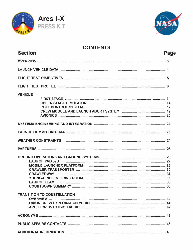
Recovery Trajectory
FIRST STAGE cont.
Ares I-XPRESS KIT
T0 Mission elapsed time from liftoffTsep Time after first stage separationH HeightV VelocityQ Maximum Dynamic Pressure

The upper stage simulator (USS) was designed and manufactured by NASA’s Glenn Research Center in Cleveland.
The USS is similar in shape and total mass to the Ares I upper stage, and will allow the flight test to have the same approximate trajectory through the first stage of flight.
The USS is unique in that it has interfaces with every other Ares I-X element, or integrated project team, including the first stage, crew module and launch abort system, and roll control system.
It also hosts more than 250 sensors, or development flight instrumentation, and several integrated data acquisition units. The data obtained from these sensors will be used to guide the engineering and final design of the Ares I launch vehicle. The USS also is home to two critical avionics devices, the flight control computer and the forward rate gyro unit.
UPPER STAGE SIMULATOR (USS)
OCTOBER 2009 14
Ares I-XPRESS KIT

Glenn utilized its local work force of highly skilled welders and on-site facilities to manufacture the USS between June 2007 and October 2008.
Steel sheets were rolled and welded into cylinders, painted and then outfitted with an internal access system, electronic sensors and cabling.
The upper stage simulator traveled to Port Canaveral, Fla., aboard the Delta Mariner, a ship that transports the Delta IV rocket for United Launch Alliance.
The journey began Oct. 22, 2008, on the Ohio River as the barge traveled toward the Mississippi River for its voyage to Port Canaveral.
The flight hardware arrived Nov. 4, 2008, and moved off the barge into High Bay 4 of the Vehicle Assembly Building at NASA’s Kennedy Space Center.
Eleven segments comprise the USS: two interstage segments, two ballast segments, five “common” segments, and the spacecraft adapter and service module.
OCTOBER 2009 15
UPPER STAGE SIMULATOR (USS) cont.
Ares I-XPRESS KIT

OCTOBER 2009 16
The interior wall of the Ares I-X rocket’s upper stage simulator.
These segments vary in height from 7 to 10 feet and weigh approximately 27,000 to 68,000 pounds.
Together they account for more than 100 feet of the total 327-foot vehicle height and almost 450,000 pounds of the Ares I-X vehicle’s liftoff weight.
Every segment was fit-checked and super stacks were created in Glenn’s Power Systems Facility to mimic assembly at Kennedy Space Center.
This process enabled the verification of the procedures to build the upper stage and eliminated potential interface problems.
Once the vehicle was integrated in High Bay 3 of Kennedy’s Vehicle Assembly Building, access above the first stage only was available via internal ladders and platforms.
The internal access door is located in Interstage 1. This internal design reduced modifications to the Vehicle Assembly Building and Launch Pad 39B.
UPPER STAGE SIMULATOR (USS) cont.
Ares I-XPRESS KIT
The upper stage simulator segments are ready for stacking in Kennedy Space Center’s Vehicle Assembly Building.

Overview • Performs 90-degree roll maneuver after vehicle clears launch tower • Controls roll attitude during flight • Includes two modules (RoCS A and B) with two engines each • Integrated into the USS
Hardware RoCS was developed by NASA’s Marshall Space Flight Center in Huntsville, Ala., with Teledyne Brown Engineering Inc. as prime contractor.
The modules are located in the lowest segment, or interstage, of the upper stage. Their thrusters are capable of generating up to 2,250 pounds (10,000 newtons) of force (at vacuum). The modules fire tangential and at right angles to the roll axis in order to provide a controlling roll torque.
The RoCS will operate from just after the rocket clears the launch tower at six seconds to just before first stage separation. As part of the USS, it is expected to break up after it falls into the Atlantic Ocean and will not be recovered.
The RoCS propulsion system components were harvested from decommissioned Peacekeeper missiles, which were to be dismantled by the U.S. Air Force as part of the second Strategic Arms Reduction Treaty. The use of Peacekeeper parts for RoCS, and space shuttle parts for the first stage, was an effective means for NASA to reduce the cost and development time of the Ares I-X flight test vehicle. The alternative would have been to design and build a new propulsion system or use and discard reaction control thrusters needed for the space shuttle.
ROLL CONTROL SYSTEM (RoCS)
OCTOBER 2009 17
Ares I-XPRESS KIT
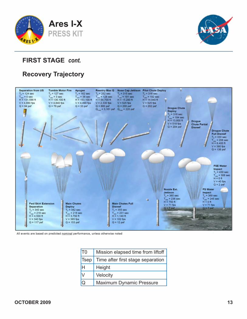
The RoCS also was “cold-flow” tested at Teledyne Brown Engineering Inc. in Huntsville, Ala. During these tests, helium-pressurized water passed through the tanks, pipes and valves to check pressurization rates and pressure peaks during engine operation. The modules were then fit-tested for assembly and installation purposes after delivery to Kennedy Space Center and before propellant loading. The fit-check testing into the USS was used to verify that the RoCS drill holes and panels matched the designated cutouts on the interstage segment and to provide installation procedure verification before installing the modules fully loaded with propellants.
Ground OperationsThe propellants -- nitrogen tetroxide (NTO) and monomethyl hydrazine (MMH) -- were loaded into the modules at Kennedy’s Hypergolic Maintenance Facility (HMF). The modules were installed into the flight test vehicle in the Vehicle Assembly Building prior to rollout to Launch Pad 39B.
OCTOBER 2009 18
Testing The thrusters were hot-fire tested at NASA’s White Sands Test Facility in Las Cruces, N.M., in 2007 and 2008 to verify they could perform the pulsing duty cycle required by Ares I-X.
The RoCS successfully was tested up to a half-second-on, one-second-off cycle. The hot-fire tests also checked for vulnerability to air-ingestion coming from the propellant lines, as will be the case during the initial roll maneuver pulse.
ROLL CONTROL SYSTEM (RoCS) cont.
Ares I-XPRESS KIT
The Ares I-X roll control system module is revealed in Kennedy Space Center’s Vehicle Assembly Building.
A roll control system thruster is hot-fire tested at NASA’s White Sands Test Facility in Las Cruces, N.M.

The topmost part of the Ares I-X rocket is formed by the crew module (CM) and associated launch abort system (LAS) mass simulators.
These precisely fabricated hardware components will contribute to a better understanding of overall vehicle aerodynamics, as well as the vehicle’s guidance, navigation and control systems. The simulators will help researchers more confidently compare flight test results with preflight predictions, an important step toward verifying analysis tools and techniques needed to further develop Ares I. The CM/LAS simulators contribute by accurately reflecting the shape and physical properties of the models used in computer analyses and the physical models used in wind tunnel tests. They will house about 150 sensors that will relay flight data to ground recorders.
While the conical module has the same basic shape as the Apollo command module, at approximately five meters in diameter, it is significantly larger. The launch abort system simulator will be positioned over and above the crew module at launch, rising 46 feet above the module.
Crew Module (CM) andLaunch Abort System (LAS)
OCTOBER 2009 19
Ares I-XPRESS KIT
Crew Module
Laun
ch A
bort
Syste
m
The sensors will measure aerodynamic pressure and temperature at the nose of the rocket, and contribute to measurements of vehicle acceleration and angle of attack. How the tip of the rocket slices through the atmosphere is important because that determines the flow of air over the entire vehicle.
The CM/LAS simulators were the first segments used to help demonstrate lifting, handling and stacking of Ares I-X flight test vehicle elements in Kennedy Space Center’s Vehicle Assembly Building. They also were used in the first of a three-part series of prelaunch ground tests to verify predicted flight dynamics during the first two minutes of flight. Strategically placed shakers imposed random loads and vibrations to determine the vehicle’s first several structural bending modes, an important confidence-builder before launch. The CM/LAS mass simulators were designed, fabricated and assembled at NASA’s Langley Research Center in Hampton, Va., and delivered to Kennedy in early 2009.

Avionics control every active portion of the Ares I-X flight test, from liftoff and navigation to data collection and parachute deployment. The avionics system functions as the rocket’s “brains” and “nervous system,” as it provides information on the environment and controls movement and direction. In addition to controlling the rocket, the avionics will be collecting, transmitting and storing engineering data before, during and after the flight. The information gathered by the avionics system will be incorporated into further computer simulations and analyses to help NASA better understand how the Ares I launch vehicle will fly and interact with its environment.
HardwareThe avionics hardware was developed by a NASA team at Marshall Space Flight Center in Huntsville, Ala., which includes Jacobs
AVIONICS
OCTOBER 2009 20
Ares I-XPRESS KIT
Engineering Group Inc. and Lockheed Martin as subcontractors. The avionics systems include four primary types of hardware:
• Fault tolerant inertial navigation unit (FTINU), developed from United Launch Alliance Atlas V avionics, which
directs the rocket in flight• Space shuttle-derived avionics (SDA), which controls the actions of the first stage, including the parachutes• New ascent thrust vector controller (ATVC), which will translate between Atlas and shuttle hardware• Developmental flight instrumentation (DFI), which will collect data on aerodynamic, vibration, thermal, thrust oscillation and other forces during flight•The ground command, control and communication (GC3) system installed in the mobile launcher platform will enable launch controllers to monitor, interact with and launch the vehicle
The ascent thrust vector controller (ATVC), part of the Ares I-X avionics hardware, undergoes testing at Marshall Space Flight Center.

AVIONICS
Ares I-XPRESS KIT
OCTOBER 2009 21
TestingThe avionics systems were integrated and tested in the Systems Integration Laboratory (SIL) at a Lockheed Martin facility in Denver. The SIL functions as a flight simulator for the computers, putting them through a variety of flight situations, much as a human pilot would be tested before flying a real aircraft. The SIL included interfaces, or connections, to simulated or actual pieces of rocket hardware as well as proper lengths of wiring to ensure a realistic interaction between computers and hardware.
Ground, Flight and Recovery OperationsAvionics hardware was installed in nearly every part of the flight test vehicle, from the crew
module and launch abort system simulators to the aft skirt of the first stage. DFI sensors were placed all along the front end of the rocket, and along the inside and outside of the upper stage simulator and first stage.
Redundant rate gyroscope units (RRGU) at the forward and aft ends of the rocket will continually monitor the rocket’s location on the ground and in space. RRGU feeds that information to the fault tolerant inertial navigation unit (FTINU), also known as the flight computer, which is mounted beneath the ballast in the middle of the upper stage simulator to minimize movement.
The first stage avionics module (FSAM), located inside the fifth segment simulator, includes batteries, controls for the first stage rocket motor, the parachute recovery system and data storage. It will be recovered and its data downloaded and analyzed after the flight.
The Ares I-X avionics systems were integrated and tested in the Systems Integration Laboratory at a Lockheed Martin facility in Denver.

The Systems Engineering & Integration (SE&I) Office, managed by NASA’s Langley Research Center in Hampton, Va., is responsible for integrating the vehicle’s components into a complete rocket and making sure they work together as a system to meet flight test objectives.
SE&I provides:• Structural, thermal and aerodynamic analyses for the overall system • Manages the mass of the vehicle • Develops the trajectory and guidance • Builds navigation and control algorithms
Key contributions include integrated design and analysis (ID&A), which serves two main purposes: • Integrating the analysis of multiple groups • Aerodynamics • Trajectory • Structures • Thermal • Guidance, navigation and control
• Accounting for the interdisciplinary interactions between all flight and ground elements
One key goal is to develop and document the vibro-acoustic environment and provide the vibro-acoustic and shock environmental criteria for liftoff, ascent and re-entry phases. It also is responsible for developmental flight instrumentation (DFI), which is comprised of more than 700 sensors mounted on the vehicle from top to bottom. The sensors will take 850 measurements -- many of them thousands of times -- during the six minutes it takes from launch to splashdown.
The office developed and manages requirements and methods to validate each mission objective down to performance requirements. The validation process involves checking subsystems to ensure they satisfy the requirement, and if not, it assesses alternatives.Proper validation is key to mission success.
SYSTEMS ENGINEERING and INTEGRATION (SE&I)
OCTOBER 2009 22
Ares I-XPRESS KIT

First Stage • Thermal control system • First stage electrical and instrumentation • Thrust vector control • Flight system safety systems
Avionics • Electrical power system • Flight control system • Vehicle health monitoring system • Ground communication command and control system
LAUNCH COMMIT CRITERIA
OCTOBER 2009 23
Ares I-XPRESS KIT
The launch commit criteria will become effective at T-4 hours and will terminate at first stage solid rocket motor ignition.
Time Action
Prior to T-4 hours Proceed with the countdown if the malfunction or problem is accept able or can be repaired in parallel with launch operations. Otherwise, hold at T-4 hours for repair or until a launch scrub is declared.
T-4 hours to T-4 minutes Proceed with the countdown if the malfunction or problem is acceptable. Otherwise, hold at T-4 minutes for repair or until a launch scrub is declared.
T-4 minutes to T-0 Any problem that occurs after T-4 minutes will result in a recycle to T-4 minutes for problem resolution.
Roll Control System • Propellant system • Thrust engine system
Ground System and Ground Operation • Ground control system • Ground pyrotechnic initiator controller • Sound suppression system
Integration • Developmental flight instrumentation • Photo optical control system • Telemetry
The following summarizes the launch commit criteria for systems that will be monitored for anomalies:

T-7 days The Ares I-X rocket rolled out during early morning hours of Oct. 20, 2009, to reduce exposure to wind, similar to the space shuttle. The rocket was connected to the mobile launcher platform by four hold-down posts through the aft skirt. In this configuration, Ares I-X was allowed to safely move because winds were not predicted to exceed 30 knots or 35 mph. Crawler-transporter speed was limited to 0.8 mph to prevent excessive loading. Winds were acceptable, allowing the vehicle to safely be secured at Launch Pad 39B. The ground operations team extended the vehicle stability system (VSS) arms from the fixed service structure and “grabbed” the rocket at the top of the first stage forward skirt. Once attached, the rocket can safely sit at the pad for 30 days with winds of 65 knots or 74 mph peak.
T-3 days, 8 hours Ordnance is installed. If a lightning violation occurs, all ordnance must be disconnected to allow system testing.
T-2 hours The vehicle stability system (VSS) is retracted and secured. Winds are not to exceed 20 knots or 23 mph from this point in the countdown until launch.
T-1 hourThe ambient temperature shall not exceed a maximum of 95 degrees F (35 degrees C), and the ambient temperature shall not drop below a minimum of 36 degrees F (2.22 degrees C) in order to maintain operational limits for the RoCS valve.
Additional weather launch commit criteria: • Do not launch for 30 minutes after any type of lightning occurs within 10 nautical miles of the flight path • Cumulus clouds near the flight path of the vehicle are to be avoided to limit precipitation forming on the vehicle • Anvil clouds near the flight path of the vehicle are to be avoided to reduce probability of lightning discharge
WEATHER CONSTRAINTS
OCTOBER 2009 24
Ares I-XPRESS KIT

NASA’s Glenn Research Center developed the upper stage mass simulator. NASA’s Langley Research Center provided aerodynamic characterization and flight test vehicle integration of the crew module/launch abort system mass simulators. NASA’s Marshall Space Flight Center provided management for the development of avionics, roll control and first stage systems. NASA’s Kennedy Space Center in Florida, provided operations and associated ground activities. ATK Space Systems, of Magna, Utah, is the prime contractor for the first stage reusable solid rocket boosters. Jacobs Technology of Tullahoma, Tenn., is the prime contractor for avionics. United Space Alliance of Houston is the prime contractor supporting launch operations at Kennedy.
PARTNERS
OCTOBER 2009 25
Ares I-XPRESS KIT

To save on time and cost, the space shuttle heritage infrastructure was modified and used to receive hardware and process the Ares I-X rocket.
Heritage facilities modified: Heritage facilities needing no modifications:
• Vehicle Assembly Building • Assembly Refurbishment Facility • Launch Pad 39B • Rotation Processing and Surge Facility • Mobile launcher platform • Hypergolic Maintenance Facility • Hangar AF • Parachute Refurbishment Facility • Launch Control Center
GROUND OPERATIONS (GO) and GROUND SYSTEMS (GS)
OCTOBER 2009 26
Ares I-XPRESS KIT

Several new pieces of hardware were added to or modified on the fixed service structure (FSS) and rotating service structure (RSS) at Launch Pad 39B. These changes include:
• Upper stage access arm -- gaseous oxygen vent arm (GVA) was modified to provide internal access to the upper stage simulator (USS) through the interstage segment. This access also supports the environmental control system (ECS) connection to the USS
• First stage environmental control system umbilical -- locally extendable and retractable arm will carry and support the environmentally controlled ducts from the FSS to the first stage ECS
OCTOBER 2009 27
LAUNCH PAD 39B
Ares I-XPRESS KIT
• First stage avionics module access -- platform was added to the RSS to provide access to the first stage’s fifth segment for launch pad processing of the first stage avionics module (FSAM) and manual mating or demating of the first stage ECS
• Environmental control system purge -- Two ECS purge ducts will keep the avionics and ground staff cool while they service the rocket. There is one purge circuit for the USS and one for the first stage and FSAM
• Lightning protection system -- New system features a large cable strung between two of the three 600-foot-tall steel and fiberglass towers. The new system will provide better protection from lightning strikes and help avoid delays to the launch schedule by collecting more information on the strike for analysis by launch managers
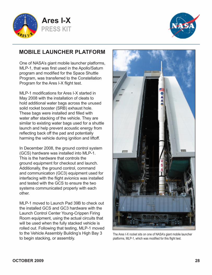
One of NASA’s giant mobile launcher platforms, MLP-1, that was first used in the Apollo/Saturn program and modified for the Space Shuttle Program, was transferred to the Constellation Program for the Ares I-X flight test.
MLP-1 modifications for Ares I-X started in May 2008 with the installation of cleats to hold additional water bags across the unused solid rocket booster (SRB) exhaust hole. These bags were installed and filled with water after stacking of the vehicle. They are similar to existing water bags used for a shuttle launch and help prevent acoustic energy from reflecting back off the pad and potentially harming the vehicle during ignition and liftoff.
In December 2008, the ground control system (GCS) hardware was installed into MLP-1. This is the hardware that controls the ground equipment for checkout and launch. Additionally, the ground control, command and communication (GC3) equipment used for interfacing with the flight avionics was installed and tested with the GCS to ensure the two systems communicated properly with each other.
MLP-1 moved to Launch Pad 39B to check out the installed GCS and GC3 hardware with the Launch Control Center Young-Crippen Firing Room equipment, using the actual circuits that will be used when the fully stacked vehicle is rolled out. Following that testing, MLP-1 moved to the Vehicle Assembly Building’s High Bay 3 to begin stacking, or assembly.
MOBILE LAUNCHER PLATFORM
OCTOBER 2009 28
Ares I-XPRESS KIT
The Ares I-X rocket sits on one of NASA’s giant mobile launcher platforms, MLP-1, which was modified for this flight test.

Historical Data
• ML-3 was first used for Apollo 10 on May 18, 1969 • Thomas Stafford, John Young and Eugene Cernan made 31 lunar orbits • Second use of ML-3 was Apollo 13 on April 11, 1970 • James Lovell, Fred Haise and John Swigert safely returned to Earth after service module oxygen tank ruptured • Third use of ML-3 was Apollo 15 on July 26, 1971 • David Scott, James Irwin and Alfred Worden made fourth moon landing • Fourth use of ML-3 was Apollo 16 on April 16, 1972 • Young, Kenneth Mattingly and Charles Duke made fifth moon landing • Fifth and final use of ML-3 prior to the start of the Space Shuttle Program was for Apollo 17 on Dec. 7, 1972 • Cernan, Ronald Evans and Harrison Schmitt made sixth and final moon landing • Dismantling of the ML-3 umbilical tower began Dec. 8, 1975, when the first of 11 sections was lowered to the ground • Modifications on ML-3 to support the Space Shuttle Program as MLP-1 were completed in 1979 • MLP-1 was first used on STS-1 on April 12, 1981 • MLP-1 was last used on STS-119 on March 15, 2009 • MLP-1 was used a total of 51 times
OCTOBER 2009 29
MOBILE LAUNCHER PLATFORM cont.
Ares I-XPRESS KIT
Statistics
• Two-story steel structure, 25 feet (7.6 meters) high, 160 feet (49 meters) long and 135 feet (41 meters) wide • Empty weight: 8.23 million pounds (3.73 million kilograms) • Height above the ground when positioned on six steel pedestals: 22 feet (7 meters) when in the Vehicle Assembly Building or at the launch pad • Four attach points on the aft skirt hold the vehicle on the mobile launcher platform and disconnect by explosive nuts that release the bolts at liftoff

The crawler-transporter moves a fully assembled vehicle, mounted on a mobile launcher platform, from Kennedy Space Center’s Vehicle Assembly Building to the launch pad. The huge tracked crawler originally was used during the Apollo era, and underwent modifications for the space shuttle and Constellation programs.
The crawler-transporter is about 20 feet (6.1 meters) high, 131 feet (40 meters) long, and 114 feet (34.7 meters) wide -- about the size of a baseball diamond. It weighs about 6 million pounds (2.7 million kilograms) unloaded. The crawler has eight tracks, each with 57 shoes, or cleats, each weighing approximately 1 ton (907 kilograms). Unloaded, it has a maximum design speed of 2 mph (3.2 kilometers), but in practice usually moves at the loaded speed of 0.8 mph. Two 2,750-horsepower diesel engines power the crawler. The engines drive four 1,000-kilowatt generators that provide electrical power to 16 traction motors. Operators in cabs on either end steer the giant vehicle.
The crawler-transporter has a leveling system designed to keep the top of the vehicle vertical while negotiating the 5 percent grade leading to the top of the launch pad. Also, a laser docking system provides almost pinpoint accuracy when the crawler-transporter and mobile launcher platform are positioned at the launch pad or in the Vehicle Assembly Building.
CRAWLER-TRANSPORTER
OCTOBER 2009 30
Ares I-XPRESS KIT
A crawler-transporter, traveling at less than 1 mph, takes the Ares I-X rocket to Launch Pad 39B at Kennedy Space Center.

The crawlerway is a 130-foot-wide (39.6-meter) roadway -- almost as broad as an eight-lane freeway. The crawler-transporter uses this for its more than 3-mile (4.8-kilometer) trek from Kennedy Space Center’s Vehicle Assembly Building to one of the launch pads.
The crawlerway consists of two 40-foot- (12-meter-) wide lanes, separated by a 50-foot- (15-meter-) wide median strip. It has four layers to support the huge weight. The top layer of the crawlerway is river gravel about 8 inches (20.3 centimeters) thick on curves and 4 inches (10.2 centimeters) thick on straightaway sections. The other layers in descending order are 4 feet (1.2 meters) of graded, crushed stone; 2.5 feet (0.76 meter) of select fill; and 1 foot (0.30 meter) of compact fill. The journey to a launch pad from the Vehicle Assembly Building takes several hours.
OCTOBER 2009 31
CRAWLERWAY
Ares I-XPRESS KIT
The first stretch of the crawlerway at Kennedy Space Center began in November 1963. The maximum crawlerway loading reported to date from any Apollo or space shuttle configuration is 18.6 million pounds. The Ares V loads are projected to be up to 35 percent larger.
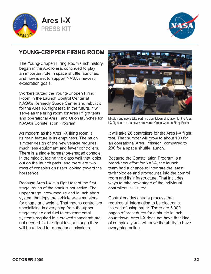
The Young-Crippen Firing Room’s rich history began in the Apollo era, continued to play an important role in space shuttle launches, and now is set to support NASA’s newest exploration goals.
Workers gutted the Young-Crippen Firing Room in the Launch Control Center at NASA’s Kennedy Space Center and rebuilt it for the Ares I-X flight test. In the future, it will serve as the firing room for Ares I flight tests and operational Ares I and Orion launches for NASA’s Constellation Program.
As modern as the Ares I-X firing room is, its main feature is its emptiness. The much simpler design of the new vehicle requires much less equipment and fewer controllers. There is a single horseshoe-shaped console in the middle, facing the glass wall that looks out on the launch pads, and there are two rows of consoles on risers looking toward the horseshoe.
Because Ares I-X is a flight test of the first stage, much of the stack is not active. The upper stage, crew module and launch abort system that tops the vehicle are simulators for shape and weight. That means controllers specializing in everything from the upper stage engine and fuel to environmental systems required in a crewed spacecraft are not needed for the flight test, although they will be utilized for operational missions.
YOUNG-CRIPPEN FIRING ROOM
OCTOBER 2009 32
Ares I-XPRESS KIT
Mission engineers take part in a countdown simulation for the Ares I-X flight test in the newly renovated Young-Crippen Firing Room.
It will take 26 controllers for the Ares I-X flight test. That number will grow to about 100 for an operational Ares I mission, compared to 200 for a space shuttle launch.
Because the Constellation Program is a brand-new effort for NASA, the launch team had a chance to integrate the latest technologies and procedures into the control room and its infrastructure. That includes ways to take advantage of the individual controllers’ skills, too.
Controllers designed a process that requires all information to be electronic instead of using paper. There are 6,000 pages of procedures for a shuttle launch countdown. Ares I-X does not have that kind of complexity and will have the ability to have everything online.

Doug Cooke, Associate AdministratorNASA’s Exploration Systems Mission Directorate
Doug Cooke is responsible for managing the development of flight hardware systems for future support of the International Space Station and the exploration of the moon, Mars and beyond. This includes development of lunar robotic precursors, critical technologies and human research to
support future human spacecraft and exploration missions. Cooke has more than 35 years of experience in the space shuttle, space station and exploration programs. He has been assigned significant responsibilities during critical periods of each, including top management positions in all three programs.
Jeff Hanley, Manager NASA’s Constellation Program
Jeff Hanley is leading the development of NASA’s new spacecraft and launch vehicle system, which will take astronauts to the moon, Mars and beyond. Prior to his leadership role with the Constellation Program, Hanley was chief of the Flight Director Office from January to December of 2005. Hanley had
been a flight director since 1996, and he achieved certification for both the International Space Station and the space shuttle. He supported several space station assembly missions as a station flight director and was the lead space station flight director for assembly mission 4A, Endeavour’s STS-97 mission. Hanley also was the lead flight director for Expedition 1 and lead shuttle flight director for the STS-110 mission.
Edward Mango, NASA Launch DirectorNASA’s Ares I-X Flight Test
Since spring 2009, Edward Mango has served as the launch director for Ares I-X, including the management and direction for the prime launch team and the launch support team. In addition, he is the leader of the launch authority team, which is responsible for programmatic authority to perform the launch
and flight test. Also, since the fall of 2008, Mango has been assigned as director of the Constellation Space Transportation Planning (CSTP) office at Kennedy Space Center. He is responsible for the development of a new program effort under NASA’s Space Operations Mission Directorate to operate and sustain the Constellation systems to the International Space Station.
LAUNCH TEAM
OCTOBER 2009 33
Ares I-XPRESS KIT

Bob Ess, Mission ManagerNASA’s Ares I-X Flight Test
In June 2007, Bob Ess assumed responsibility for overall project management and direction of the developmental flight test through the Ares I-X Mission Management Office. The office is responsible for the integration of the launch vehicle system and the ground operations system within the Constellation
Program Office. Prior to his appointment as mission manager, Ess served as the chief of flight test for the Constellation Program at NASA’s Johnson Space Center. In this position, he was responsible for developing an integrated flight test strategy and defining flight test objectives for the Constellation Program.
Jon Cowart, Deputy Mission ManagerNASA’s Kennedy Space Center
In 2007, Jon Cowart became the senior project manager responsible for all modifications to Launch Pad 39B, the Vehicle Assembly Building and mobile launcher platform for the Ares I-X flight test. In December 2008, he was chosen deputy mission manager for Ares I-X. As part of the Mission
Management Office, he is responsible for the entire Ares I-X flight test mission. Before his current assignment supporting Ares I-X, Cowart was the manager of the Orbiter Sustaining Engineering Office at NASA’s Kennedy Space Center, representing the Orbiter Project Office located at the Johnson Space Center. The office was responsible for all design engineering problems and changes encountered and implemented at Kennedy.
Steve Davis, Deputy Mission ManagerNASA’s Marshall Space Flight Center
In 2006, Steve Davis began supporting the management of the Ares I-X flight test mission. He supports the mission manager and has special oversight responsibilities for the design, development and integration of the flight test vehicle’s first stage, avionics and roll control systems at the Marshall Space
Flight Center.Before his current assignment of supporting Ares I-X, Davis was deeply involved in the 2005 Exploration Systems Architecture Study (ESAS) at NASA Headquarters, which established the basic configurations for the Ares launch vehicles being built today. That work led directly to developing a flight test program, which eventually included Ares I-X.
OCTOBER 2009 34
Ares I-XPRESS KIT
LAUNCH TEAM cont.

NASA’s Integrated Product Team Leadership:
Marshall Smith, Langley, Systems Engineering and Integration ChiefChris Calfee, Marshall, First Stage ManagerVince Bilardo, Glenn, Upper Stage Simulator ManagerJonathan Cruz, Langley, Crew Module/Launch Abort System ManagerRon Unger, Marshall, Roll Control System ManagerKevin Flynn, Marshall, Avionics ManagerMike Stelzer, Kennedy, Ground Systems Manager Tassos Abadiotakis, Kennedy, Ground Operations ManagerJoe Brunty, Marshall, Chief EngineerShaun Green, Kennedy, Chief EngineerDan Mullane, Marshall, Chief Safety and Mission Assurance OfficerBruce Askins, Marshall, Project Integration Manager
Ares I-XPRESS KIT
LAUNCH TEAM cont.
Constellation Program Manager, Jeff Hanley• Overall NASA “go-no go” authority • Provide agency and Constellation Program perspective of advisability to proceed with launch • Provide risk acceptance• Provide agency vote on risk discussions deemed acceptable by LAT, technical authority and chief safety officer• Receive and consider alternate opinions
Ares I-X Launch Director, Edward Mango• Prime launch team, PLT, authority• Facilitate risk discussions with LAT and PLT• Performs readiness poll(s)• Maintain situational awareness/objective perspective of countdown activities and advise LAT• Receive alternate opinion feedback and facilitate resolution
Ares I-X Mission Manager, Bob Ess• Ares I-X hardware authority• Provide Ares I-X perspective of advisability to proceed with launch • Provide Ares I-X team risk acceptance vote • Provide Ares I-X vote on risk discussions• Receive and consider alternate opinions
OCTOBER 2009 35
NASA’s Launch Authority Team roles and responsibilities: • Program requirements change authority • Disposition of undocumented programmatic risks • Disposition of increases to programmatic risks

T-7 hours • First weather balloon is launched to collect atmospheric thermal properties
T-4 hours, 30 minutes • Technicians remove the external environmental control systems that provide cool airflow to the vehicle • Onboard navigation unit begins system alignment • Additional subsystems complete testing and remain powered on • First stage avionics module (FSAM) access platform is retracted
T-3 hours, 30 minutes • Six additional weather balloons begin to launch to evaluate if the conditions are suitable for flight
T-3 hours • Fault tolerant inertial navigation unit (FTINU) completes alignment and begins navigation testing
T-2 hours, 30 minutes • C-band beacon transponder is powered up and tested with the range • Range safety system verification walk down is completed • Auxiliary power unit is verified for system health
T-2 hours • VSS is retracted and secured • Ground control station (GCS) system begins monitoring for commands from the Launch Control Center • Sound suppression water control is transferred to the GCS • Video, operational flight instrumentation (OFI) and developmental flight instrumentation (DFI) are checked
T-1 hour, 45 minutes • Safety personnel begin the process of securing launch pad
T-1 hour, 15 minutes • Ground command, control and communication initiates launch commit criteria monitoring • Developmental flight instrumentation covers are removed • FTINU executes final alignment after the VSS is retracted
COUNTDOWN SUMMARY
OCTOBER 2009 36
Ares I-XPRESS KIT

T-1 hour • All personnel depart Launch Pad 39B for the safe haven • Range verifies all “go/no-go” interfaces
T-43 minutes • Flight termination system is activated and set to safe
T-30 minutes • DFI, with the exception of cameras, are powered on and recording
T-4 minutes, built-in hold • Enter 10-minute built-in hold • Vehicle can remain in this hold status for up to four hours • Six video cameras and low power transmitters are powered up • Telemetry is verified and readiness for launch established • Range safety issues cleared for launch • Countdown clock initiates automated count
T-3 minutes, 55 seconds and counting • Sound suppression system is verified for pressure, water tank level and power • Flight termination system and solid rocket motor ignition are set to arm • Power to avionics cooling fans is terminated • Onboard data recorder begins taking data
T-1 minute, 40 seconds • Flight control system is enabled and prepared for flight • Inertial measurement subsystem executes final alignment
T-1 minute, 20 seconds • Flight control system receives the start count • Signal is sent to the OFI and DFI data streams to synchronize
T-35 seconds • Flight control system transfers from alignment to navigation mode • Inertial and navigation data are verified for accuracy • Auxiliary power unit start sequence is initiated
T-21 seconds • Reusable solid rocket motor (RSRM) thrust vector control (TVC) gimbal test performed by rocking and tilting each axis approximately 1.5 degrees
OCTOBER 2009 37
COUNTDOWN SUMMARY cont.
Ares I-XPRESS KIT

T-16 seconds • Ground control station issues commands for sound suppression, opening the valves to flood the mobile launch platform with water • At its peak, water will flow at a rate of 900,000 gallons per minute
T-0, liftoff • RSRMs ignite and hold-down bolts fire.
T+0.225 seconds • Liftoff • Pyrotechnics fire, releasing umbilicals attached to the vehicle
T+6 seconds • Vehicle clears the launch tower • Sound suppression system is secured
T+20 seconds • Roll control system is turned off for one second out of every 10 • This provides an opportunity to characterize roll torques on the vehicle, which is a primary mission objective
T+34 to 44 seconds • First test maneuver is executed on the rocket during ascent • This will help determine the flight dynamics characteristics, satisfying the primary mission objective of demonstrating control of a vehicle that is dynamically similar to the Ares I/Orion vehicle using Ares I-relevant flight control algorithms
T+50 seconds • Final weather balloon is launched to 59,000 feet
T+1 minute, 33.6 seconds • Final test maneuver is executed for structural mode identification
T+1 minute, 55 seconds • Sequencer begins looking for RSRM burnout • When filtered accelerations drop below 7.14 feet per second
OCTOBER 2009 38
Ares I-XPRESS KIT
COUNTDOWN SUMMARY cont.

T+2 minutes, burnout + 0 seconds • Nominal RSRM burnout • Safe and arm is commanded to safe
T+2 minutes, 1 second to 2 minutes, 3 seconds, burnout phase • DFI switches from ascent video to recovery video • Flight termination system is shutdown and power removed • Roll control system is disabled • Auxiliary power units are shut down
T+2 minutes, 3 seconds, burnout + 3 seconds • Booster deceleration motors mounted on the first stage aft skirt fire, slowing the first stage for separation from the upper stage simulator (USS)
T+2 minutes, 3.04 seconds, separation + 0 seconds • Upper stage simulator and first stage separate at approximately 130,000 feet • USS will continue its trajectory and land in the Atlantic Ocean
T+2 minutes, 6 seconds, separation + 3 seconds • Booster tumble motors fire on the first stage • Critical to slowing for safe recovery
T+2 minutes, 33 seconds, separation + 30 seconds • Recovery control unit (RCU) is armed for altitude-based events • The RCU is the computer that executes various commands to ensure a successful recovery of the first stage
T+5 minutes, 3 seconds, separation + 3 minutes • RCU senses an altitude of 16,000-17,000 feet and jettisons the aeroshell to deploy pilot chutes
T+5 minutes, 33 seconds, separation + 3 minutes, 30 seconds • RCU senses an altitude of 4,200-4,600 feet and separates the forward skirt extension to deploy main chutes
T+6 minutes, 9 seconds, separation + 4 minutes, 6 seconds • RCU severs the first stage nozzle in preparation for splashdown
OCTOBER 2009 39
Ares I-XPRESS KIT
COUNTDOWN SUMMARY cont.

OVERVIEW
Established in 2005, NASA’s Constellation Program was established to continue U.S. leadership in space by developing an exploration system that eventually would allow a sustained human presence beyond low Earth orbit.
The program consists of the Ares I rocket to loft astronauts to low Earth orbit for trips to the International Space Station, or to rendezvous with an Earth departure stage carried up by the Ares V heavy lift launcher for missions to other destinations in the solar system.
During the past four years, the Constellation Program has developed detailed requirements for the many components necessary for the next steps in human spaceflight. The program has completed the preliminary design phase for both the Orion crew exploration vehicle and the Ares I crew launch vehicle, and has begun to develop the infrastructure needed for humans to explore beyond low Earth orbit.
With four years of preliminary design work complete, component testing is under way for both the Ares I and Orion. In addition to extensive computer design, analysis and simulation work, NASA already has conducted motor and engine test firings, parachute drop tests, airbag landing tests, thermal protection system tests and vehicle wind tunnel tests.
Initial operational capability of Ares I and Orion -- a crewed flight to the International Space Station -- is targeted for March 2015.
Ares I-X will be the first demonstration flight of the technologies being developed for the new launch vehicle system.
The Orion project will conduct its first major test on its new launch abort system -- the Pad Abort 1 (PA-1) launch -- from the White Sands Missile Range in New Mexico in early 2010. The system will allow the crew to escape if problems develop on the launch pad or during ascent to orbit after launch. PA-1 will be followed by a series of increasingly complex flight tests on the pad and ascent abort systems.
TRANSITION TO CONSTELLATION
OCTOBER 2009 40
Ares I-XPRESS KIT
ORION CREW EXPLORATION VEHICLE
Orion is named for one of the brightest, most familiar and easily identifiable constellations.
The Orion crew exploration vehicle will succeed the space shuttle as NASA’s primary vehicle for human space exploration. Orion looks similar to the Apollo command module, but it will be larger and more versatile, with the capability of transporting four crew members into low Earth orbit.
The crew module’s conical shape is the safest and most reliable for re-entering Earth’s atmosphere.
Designed for maximum crew operability and safety, the new spacecraft will consist of a crew module, service module, spacecraft adapter and launch abort system. It will measure about 16.4 feet in diameter, 50.3 feet in height and have a mass of about 25 tons.
The module’s new launch abort system will greatly improve astronaut safety by providing a safe, reliable method of pulling the crew out of danger in the event of an emergency on the launch pad or during the climb to Earth orbit. Mounted at the top of the Orion and launch vehicle stack, the abort system will be capable of automatically separating the spacecraft from the rocket at a moment’s notice and setting the stage for a safe landing.
The crew module includes a pressurized crew transfer tunnel and docking device capable of mating with the International Space Station. Other features include fiber optic systems and a digital control system -- such as those used in today’s most advanced aircraft. And, for the first time in NASA history, the spacecraft will use onboard sensors and computers to automatically dock with the space station. Gemini, Apollo and shuttle all required manual piloting for docking.
As with Apollo, the spacecraft will land in the ocean. This time the spacecraft will not land along the eastern U.S. coast, instead it will land near the western coast, within 200 miles of the Navy’s San Clemente Island Range Complex. It also will be able to land on solid ground, should that become necessary.
Orion’s first flight with astronauts on board is planned for 2015 to the International Space Station.
OCTOBER 2009 41
Ares I-XPRESS KIT

ARES I CREW LAUNCH VEHICLE
NASA is designing, testing and evaluating hardware and related systems for its Ares I rocket. Ares I is an in-line, two-stage rocket topped by the Orion crew exploration vehicle, its service module and a launch abort system. The combination of the rocket’s configuration and Orion’s launch abort system, which can move astronauts away quickly in case of a launch emergency, will improve crew safety.
The launch vehicle’s first stage is a single, five-segment reusable solid rocket booster derived from the Space Shuttle Program’s four-segment reusable solid rocket booster. A newly designed forward adapter called a frustum will mate the vehicle’s first stage to the second, and will be equipped with booster separation motors to disconnect the stages during ascent.
The second, or upper, stage is being designed at NASA’s Marshall Space Flight Center in Huntsville, Ala. Much like the upper stage for the Ares V cargo launch vehicle, the Ares I upper stage is propelled by a J-2X main engine fueled with liquid oxygen and liquid hydrogen.
The J-2X is an evolved variation of two historic predecessors:
• The powerful J-2 upper-stage engine that propelled the Apollo-era Saturn IB and Saturn V rockets to the moon• The J-2S, a simplified version of the J-2 developed and tested in the early 1970s.
During the first two-and-a-half minutes of flight, the first stage booster powers the vehicle to an altitude of about 187,400 feet (35.5 miles) and a speed of Mach 5.7. After its propellant is spent, the reusable booster separates and the upper stage’s J-2X engine ignites and powers the Orion spacecraft to an altitude of about 425,328 feet (80 miles). Then, the upper stage separates and Orion’s service module propulsion system completes the trip to a circular orbit of 976,800 feet (185 miles) above Earth.
The Ares I effort and associated hardware and propulsion element teams are led by the Ares Projects Office at Marshall, on behalf of the Constellation Program, at NASA’s Johnson Space Center in Houston, and NASA’s Exploration Systems Mission Directorate in Washington. ATK Launch Systems near Brigham City, Utah, is the prime contractor for the first stage. Pratt & Whitney Rocketdyne in Canoga Park, Calif., is the prime contractor for the Ares I upper stage J-2X engine. The Boeing Co. in Huntsville, Ala., is the prime contractor responsible for manufacture and assembly of the upper stage and avionics systems integration and checkout.
OCTOBER 2009 42
Ares I-XPRESS KIT

OCTOBER 2009 43
Ares I-XPRESS KIT
5SS fifth segment simulator
AIT assembly, integration and test
ARF Assembly and Refurbishment Facility
ATVC ascent thrust vector controller
BDM booster deceleration motor
BTM booster tumble motor
CDR Critical Design Review
CG center of gravity
CM/LAS crew module/launch abort system
DAC design analysis cycle
DFI developmental flight instrumentation
ECS environmental control system
EELV evolved expendable launch vehicle
FS first stage
FSAM first stage avionics module
FTINU fault tolerant inertial navigation unit
FTS flight termination system
FTV flight test vehicle
g Gravity
GFE government-furnished equipment
GN&C guidance, navigation and control
ACRONYMSGO ground operations
GRC Glenn Research Center
GS ground systems
GSE ground support equipment
HMF Hypergolic Maintenance Facility
IPT integrated product team
IS interstage
K ft. thousands of feet
kg kilogram
K lb. thousands of pounds
kPa kilopascal
KSC Kennedy Space Center
LaRC Langley Research Center
LAT Launch Authority Team
LC launch complex
LCC Launch Control Center
LCC launch commit criteria
m meter
MLP mobile launch platform
MMO Mission Management Office
MPSS main parachute support system

OCTOBER 2009 44
Ares I-XPRESS KIT
ACRONYMS cont.
MSFC Marshall Space Flight Center
NASA National Aeronautics and Space Administration
nm nautical miles
OFI operational flight instrumentation
OML outer mold line
PLT Prime Launch Team
RoCS roll control system
RPSF Rotation, Processing and Surge Facility
secs seconds
SDA solid rocket booster-derived avionics
SIL Systems Integration Laboratory
SRB solid rocket booster
TRR Test Readiness Review
TTR Table Top Review
ULA United Launch Alliance
USS upper stage simulator
VAB Vehicle Assembly Building
VSS vehicle stabilization system

OCTOBER 2009 45
Ares I-XPRESS KIT
Grey Hautaluoma, NASA Headquarters202-358-0668, [email protected]
Ashley Edwards, NASA Headquarters202-358-1756, [email protected]
Lynnette Madison, Johnson Space Center281-483-5111, [email protected]
Amber Philman, Kennedy Space Center321-867-2468, [email protected]
Dan Kanigan, Marshall Space Flight Center256-544-6849, [email protected]
Katherine Martin, Glenn Research Center216-433-2406, [email protected]
Keith Henry, Langley Research Center757-864-6120, [email protected]
Jessica Rye, ATK Space Systems321-328-2468, [email protected]
Trina Patterson, ATK Space Systems801-251-3517, [email protected]
Tracy Yates, United Space Alliance321-861-3956, [email protected]
Marion LaNasa, Avionics: Lockheed Martin504-257-1307, [email protected]
Eileen Heaton, Roll Control System: Teledyne256-726-1319, [email protected]
PUBLIC AFFAIRS CONTACTS
OCTOBER 2009 46
Ares I-XPRESS KIT
Ares I-X: www.nasa.gov/aresIX
Constellation Program: www.nasa.gov/constellation
NASA TV: www.nasa.gov/ntv
Kennedy Space Center Media Gallery: http://mediaarchive.ksc.nasa.gov
Blog: http://blogs.nasa.gov/cm/blog/Ares%20I-X/
Twitter: twitter.com/NASA_Ares_I_X
Facebook: www.facebook.com/group.php?gid=77195835389&ref=mf
Flickr: www.flickr.com/photos/28634332@N05/sets/72157610311312927/
Wikipedia: http://en.wikipedia.org/wiki/Ares_I-X
ADDITIONAL INFORMATION