Embed Size (px)
Citation preview

Arctic RS-485 / RS-422

RS- 485• Also known as RS-485 Half Duplex, RS-485 2-wire• same pair is used to transmit and receive data• only one device can transmit on the bus simultaneously because the bus is shared
• in theory there could be multiple masters and also slaves could speak with each other but typically used on ”single master – multiple slaves” setup communicating with request-reply type of protocol
MASTER
SLAVE SLAVE SLAVE
+ -
+ - + - + -
REQUEST
REPLY
A
B
RS- 422• Also known as RS-485 Full Duplex, RS-485 4-wire• separate pairs for transmit and reception• only one device can command the bus, slaves can’t speak
with each other• device can transmit and receive simultaneously (full duplex)• typically used on ”single master – multiple slaves” setup
REQUEST
MASTER
+ - + -
TX RX SLAVE
+ - + -
TX RX
SLAVE
+ - + -
TX RX
REPLY

Voltages• RS-485 and RS-422 use differential (balanced)
signalling providing good noise immunity• Generally non-inverting line is called positive, +, A or Y• Generally inverting line is called negative,-,B or Z• If voltage between A-B (Vdiff) is >200mV receiver
detects state ”1” and if A-B is below -200mV receiver detects state ”0”
• Usually transmitters drive >1,5V for state ”1” and <-1.5V for state ”0” leaving good margin to 200 mV trigger level
A
B
Vdiff = A-B
Loading• Each device causes capacitive and resistive load to bus • If the load is too big the minimum ”200 mV” signal
difference may not be reached or the signal waveform becomes too disturbed to detect the start bit
• Also termination and biasing loads the bus• Also the length of the cable and serial speed affects the
performance• Because the implementation between devices vary a lot
(e.g. some has internal termination) the only sure way is to measure the differential waveform (at both ends of the bus) with oscilloscope
• Note that the RS-485 has both ”transmit” and ”receive” phases, both have to exceed the 200 mV limit
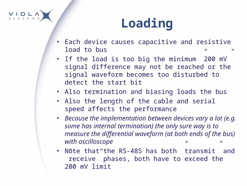
Grounding• Allthrough data transmission is balanced grounding may
be required if the distance between devices is long and/or they don’t othervise share the common ground
• The most common reason for RS-485/422 circuit damages is the excessive potential difference between the devices
• When separate grounding is required use 100R resistor to connect each remote device to common ground wire. The resistor should be rated for at least 0.5 Watts.
MASTERSLAVE SLAVE SLAVE
+ -+ - + - + -
A
BGND

Termination• Usually short lines do not require termination• Usually small data rates (<115200 bps) do not require
termination• The purpose of the termination is to cancel/attenuate the
reflections on the bus the value of termination resistor should match the characteristic impedance (Z0) of the cable
• Typically twisted-pair type of cables have Z0 100-120 (e.g. CAT-5 has 100 )
• Termination is most effective on the receiving end• Note that the termination causes plenty of load to the
bus, increases idle state power consumption and should be used only when required
• ”AC termination” does not increase idle state power consumption but is not as effective as pure resistive termination

Termination placement
MASTER
+ - + -
TX RX SLAVE
+ - + -
TX RX
SLAVE
+ - + -
TX RX
MASTER
SLAVE SLAVE SLAVE
+ -
+ - + - + -
RS-485
RS-422

Arctic Termination• Arctic internal termination is ”AC termination” • The termination is available between RS2 pins 2 and 8
(RS-422 receive pins) when DIP switch 4 is ”ON”• If termination is required on RS-485 (2-wire) mode pins
2-7 and 3-8 must be connected manually
120R
10 nF
PIN 2
PIN 8
DIP 4

Biasing• When the tranmitters are not active the line may float
causing e.g. detection of false start bits• The purpose of biasing is to tie the bus to known state
when idle• Most modern RS-422/485 receivers have internal ”fail-
safe” biasing • However if termination is used the internal ”fail-safe”
biasing may not be enough and external biasing is required
• Placement of biasing is not that sensitive as termination
> 200 mV when idle A
B

Arctic Biasing• Arctic biasing uses 3.3V voltage and 560R resistors• The biasing is available between RS2 pins 2 and 8
(RS-422 RX pins) when DIP switchs 1 and 3 are ”ON”• If biasing is required on RS-485 (2-wire) mode pins 2-
7 and 3-8 must be connected manually
3V3
PIN 8
560R
560R
PIN 2
DIP 1
DIP 3

Arctic DIP Switches and RS2 pinout
• DIP switches control the operation of RS2
• RS2 pinout (standard male DB-9)
• RS2 in RS-422/485 mode
RS-485 termination0=off, 1=onTERMINATION4
RS-485 biasing0=off, 1=onBIAS3
Selects between full-duplex (4-wire) and half-duplex (2-wire) RS-485 operation
0=full, 1=halfFULL/HALF2
Selects RS-port operation0=RS-232, 1=RS-485RS-232/RS-4851
ExplanationStateFunctionNumber
RS-485 termination0=off, 1=onTERMINATION4
RS-485 biasing0=off, 1=onBIAS3
Selects between full-duplex (4-wire) and half-duplex (2-wire) RS-485 operation
0=full, 1=halfFULL/HALF2
Selects RS-port operation0=RS-232, 1=RS-485RS-232/RS-4851
ExplanationStateFunctionNumber
Pin RS-485 FD (4-wire) RS-485 HD (2-wire)12 RXD+ (in)3 TXD- (out) TXD/RXD- (out/in)45 GND GND67 TXD+ (out) TXD/RDX+ (out/in)8 RXD- (in)9

Arctic RS- 485 howto• Set DIP switches 1 and 2 ”ON” which causes RS2 to be on RS-485 (Half-
Duplex) mode• If biasing is required set DIP switch 3 to ”ON” and manually connect Arctic RS2
pins 2-7 and 3-8 together• If termination is required set DIP switch 4 to ”ON” and manually connect Arctic
RS2 pins 2-7 and 3-8 together• Connect Arctic pin 7 (TXD/RXD+) to other device non-inverting pin (usually
marked positive,TXD/RXD+,+,A or Y)• Connect Arctic pin 3 (TXD/RXD-) to other device inverting pin (usually marked
negative,TXD/RXD-,-,B or Z)• Connect Arctic pin 5 (GND) to common ground wire (with 100R resistor in
series if the distanse is long and devices do not othervise share common ground)
• NOTE! When using RS-422/RS-485 Arctic RS2 handshaking must be set to ”none” in application configuration
7
3
2
8
ARCTIC DEVICE
+ / A / Y
- / B / Z
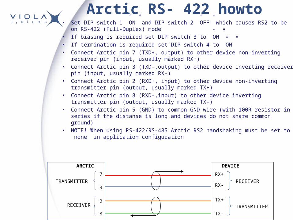
Arctic RS- 422 howto• Set DIP switch 1 ”ON” and DIP switch 2 ”OFF” which causes RS2 to be on RS-422
(Full-Duplex) mode• If biasing is required set DIP switch 3 to ”ON” • If termination is required set DIP switch 4 to ”ON” • Connect Arctic pin 7 (TXD+, output) to other device non-inverting receiver pin (input,
usually marked RX+)• Connect Arctic pin 3 (TXD-,output) to other device inverting receiver pin (input,
usually marked RX-)• Connect Arctic pin 2 (RXD+, input) to other device non-inverting transmitter pin
(output, usually marked TX+)• Connect Arctic pin 8 (RXD-,input) to other device inverting transmitter pin (output,
usually marked TX-)• Connect Arctic pin 5 (GND) to common GND wire (with 100R resistor in series if the
distanse is long and devices do not share common ground) • NOTE! When using RS-422/RS-485 Arctic RS2 handshaking must be set to ”none”
in application configuration
3
2
7
8
ARCTIC DEVICE
RX+
RX-
TX+
TX-
TRANSMITTER
TRANSMITTERRECEIVER
RECEIVER