Embed Size (px)
Citation preview

ELECTRICAL SPECIFICATIONS
PART 1 – GENERAL RELATED WORK
A. All of the work executed under this section shall meet the requirements of related disciplines as if fully stated herein.
B. See all contract documents for other requirements including as applicable General Conditions, Bidding
and Construction Schedule, Safety Requirements, Mobilization Requirements, and other Contract Terms and Conditions.
C. All Contract Documents, including but not limited to Plans, Specifications, Instructions to Bidders, and
other published documents are a part of the Contract. FIRE PROTECTION
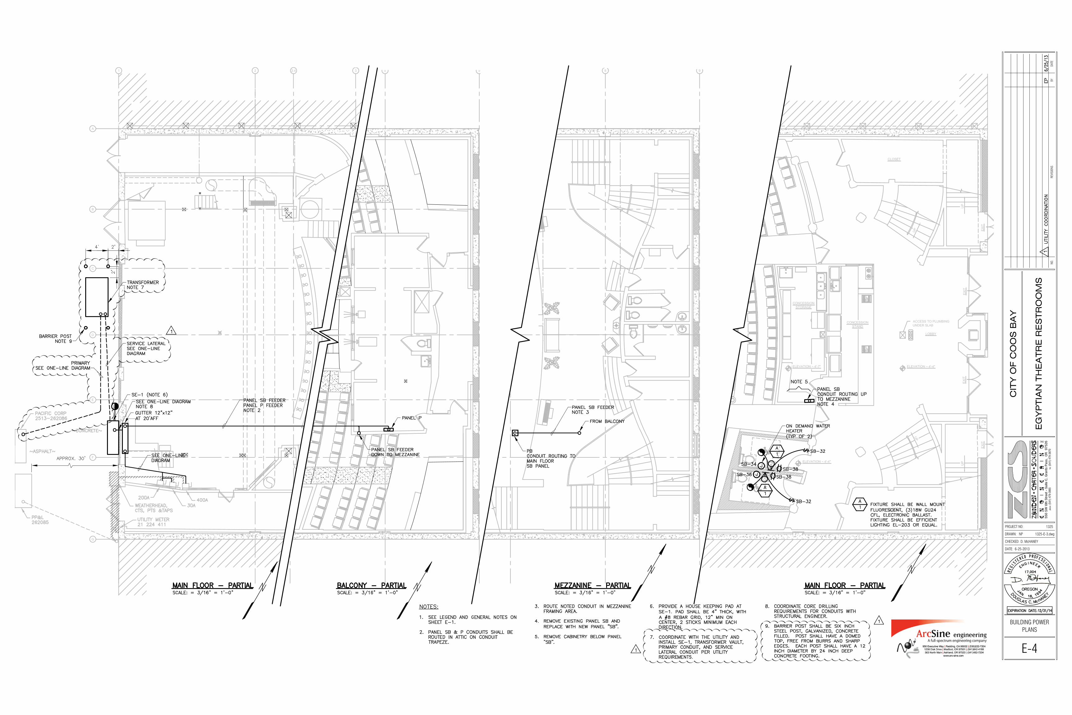
A. See Structural documents for fire-stopping requirements, and comply with State Fire Marshal requirements for approved and listed fire-stopping systems. See Structural Drawings for fire-stop finish details. At a minimum, penetration of fire rated walls, floor-ceilings, and roof-ceilings shall meet UBC Sections 709 and 710.
CODES, PERMITS, AND REGULATIONS
A. Perform all work, furnish and install all materials and equipment in full accordance with the latest applicable rules, regulations, requirements, and specifications of the following:
1. Local laws and ordinances 2. State and Federal laws 3. National Electrical Code (NEC) 4. Oregon Electrical Specialty Code (OESC) 5. Underwriters Laboratories (UL) 6. Local Utility Company
B. Wherever the requirements of the specifications or drawings are in conflict with the items above, the
more stringent requirement shall prevail. C. Obtain all permits and pay all fees required by any governmental agency having jurisdiction of the
work. Arrange all inspections required by these agencies. On completion of the work, furnish satisfactory evidence to the Owner that the work is acceptable to the regulatory authorities having jurisdiction.
SUBMITTALS
A. Before any material is fabricated or shipped, furnish to the Engineer full details, shop drawings, dimensions, catalog cuts, schematic (elementary) diagrams, wiring diagrams, and other descriptive matter as required to fully describe the products specified under this Section.
B. For service entrance equipment, meter base, and other related materials, obtain written approval of
submittals from the serving utility before submitting to the Engineer. Submittals shall include manufacturer UL listed series rated information sheets. All equipment shall be separately labeled per requirements of the NEC.
WARRANTY
A. The work and materials covered in this Section shall be guaranteed for a period of 1 year from the date of acceptance thereof against defective materials, design, and workmanship.
PART 2 – PRODUCTS GENERAL
A. Unless otherwise indicated, provide all first-quality, new materials and equipment, free from any defects, in first class condition, with ratings as shown on these drawings, and suitable for the space provided.
B. Like items of equipment provided hereunder shall be the end products of one manufacturer in order to
achieve standardization for appearance, operation, maintenance, spare parts, and manufacturer’s service.
C. Furnish labor, materials, and equipment as necessary to deliver complete and operable systems.
MATERIALS
A. Provide a meter base(s), main service panel(s), main breaker(s) with copper bussing, and other materials and work that will provide service to the facility. Short circuit rating of equipment shown on the drawings may be met using UL listed series-rated components. Materials and work shall be UL listed and shall meet the requirements of EUSERC and the utility company.
B. Lighting and power distribution panel boards: Provide circuit breaker panel boards meeting standards
established by UL, NEMA PB1, and the NEC. Where used as service entrance equipment, provide panels having UL approval for that use. Provide panels rated for the available short circuit current of the electric system. Panelboards shall include bolt on breakers.
C. Conductor sizes indicated are based on copper conductors. Do not provide conductors smaller than
those indicated. Conductors shall be stranded THWN (wet) or THHN (dry), except solid conductors may be used for 15-, 20-, and 30-amp branch circuits.
PART 3 – EXECUTION GENERAL
A. Work shall be performed in a workman like manner by craftsmen skilled in the particular trade. Work shall be performed in accordance with the drawings, specifications, manufacturer’s recommendations, and the best practice of the trade. Completed work shall present a neat and finished appearance.
B. Field verify dimensions, equipment, structural elements, and materials indicated as existing.
INSTALLATION
A. Locations of electrical equipment, and other electrical system components shown on drawings are approximate unless dimensioned. Check for and resolve conflicts with openings, structural members, and equipment having fixed locations.
B. Do not cut or notch any structural member or building surface without specific approval of the
Engineer. Carefully carry out any cutting, channeling, chasing, or drilling of floors, walls, partitions, ceilings, paving, or other surfaces required for the installation, support, or anchorage of conduit, raceways, or other electrical materials and equipment. Following such work, restore surfaces neatly to new condition using skilled craftsmen of the trades involved, at no additional cost to the Owner. Any penetrations to fire rated materials shall be restored to equal rating as required by the state Fire Marshall.
C. Follow manufacturer’s installation instructions explicitly, unless otherwise indicated.
D. Thoroughly document all electric circuits. Provide a typewritten circuit directory on all branch panels.
E. Provide engraved nameplates for all pieces of equipment. Plates shall be screw on 3 ply, black face,
white 1/4-inch-high Gothic lettering. When equipment or instrument is not suitable for a screw on nameplate, use a 16 gauge, 304 stainless steel tag, 1/4” high lettering affixed to equipment with stainless steel wire.
F. Coordinate equipment seismic bracing requirements with the local authorities and manufacturer of
equipment.
G. Completed work shall present a neat and finished appearance. Furnish and install incidental items not specifically shown or required by good practice to provide a complete electrical system.
RACEWAYS
A. Install conductors in raceways. B. Minimum size conduit shall be 1/2 inch, except 3/4 inch for underground and embedded conduit. Use
the following types of conduit for the locations listed unless indicated otherwise:
1. Use galvanized rigid steel conduit (GRS) outdoors and in wet locations.
2. Use electrical metallic tubing (EMT) in concealed locations and exposed, interior, dry locations, and where dropping from above the electrical equipment more than 6 feet above the floor.
3. Use rigid polyvinyl chloride (PVC) conduit for buried and embedded locations, except use
galvanized rigid steel (GRS) at least 5 feet on both sides of penetrations through footings and outside walls, under equipment mounting pads, where embedded in exterior light pole foundations, and where conduit changes from underground to exposed or from embedded to exposed.
4. Use liquid-tight flexible conduit for final connection to mechanical equipment.
C. All empty conduits shall be provided with a flat pull tape (mule tape or equal). D. For steel conduit installed underground, wrap the entire length with tape using 1/2-inch overlap. Use
PVC-based pressure-sensitive all-weather tape, 20-mil minimum thickness, as recommended by the manufacturer for corrosion protection of underground conduits. Tape shall be Scotchwrap 51 or equal.
GROUNDING
A. Complete electrical system shall be grounded in accordance with the presently adopted edition of the NEC Article #250, and as shown on the drawings.
B. Ground the neutral of all wiring systems in strict accordance with the NEC, State, and other applicable
laws and regulations.
C. Ground all exposed non-current-carrying metallic parts of electrical equipment and raceway systems.
D. Ground metal sheathing and any exposed metal vertical structural elements of buildings. Bond any metal equipment platforms, which support electrical equipment to that equipment.
E. At the request of, and in the presence of the authorized inspector, the contractor shall provide system
resistance readings. STARTUP AND TESTING
A. After the electrical system installation is completed, conduct an operation test for approval. Demonstrate to the Owner that the equipment operates in accordance with the requirements of these specifications and drawings.
PROJECT CLOSEOUT
A. At the completion of the project, the Contractor shall:
1. Submit operation and maintenance manuals, with tab dividers separating specific systems or items of equipment. Equipment warranties shall be included.
2. Submit a list of recommended spare parts.
3. Submit marked up “As-Built” drawings with final installed arrangements, including equipment
model numbers and performance data.
LOADS ( 17,000 SF)@ 2 VA / SF C 34000 VA
1 VA / SF 17000 VA
MARQUEE (FUTURE) C 21600 VA
SOUND EQUIPMENT (FUTURE) 36000 VA
THEATRICAL LIGHTING (FUTURE) 96000 VA
SNACK BAR (FUTURE) 51000 VA
PROJECTOR 12600 VA
SPOT LIGHTS (TWO) 3400 VA
TABLE REWINDER 1200 VA
HVAC (FUTURE) 167000 VA
WATER HEATER 12000 VA
TOTAL CONNECTED LOAD 451800 VATOTAL DEMAND LOAD (CONTINUOUS LOADS @ 125%) 465700 ADEMAND LOAD 1294 ASERVICE EQUIPMENT BUS RATING 1600 A
RECEPTACLES,
LOAD SUMMARY PANEL LOADS
LIGHTING (CONTINUOUS)