Embed Size (px)
Citation preview
Architectures and Applications for Wireless Sensor
Networks (01204525)
Physical Layer
Chaiporn [email protected]
Department of Computer EngineeringKasetsart University
Materials taken from lecture slides by Karl and Willig
2
Overview Frequency bands Modulation Signal distortion – wireless channels From waves to bits
3
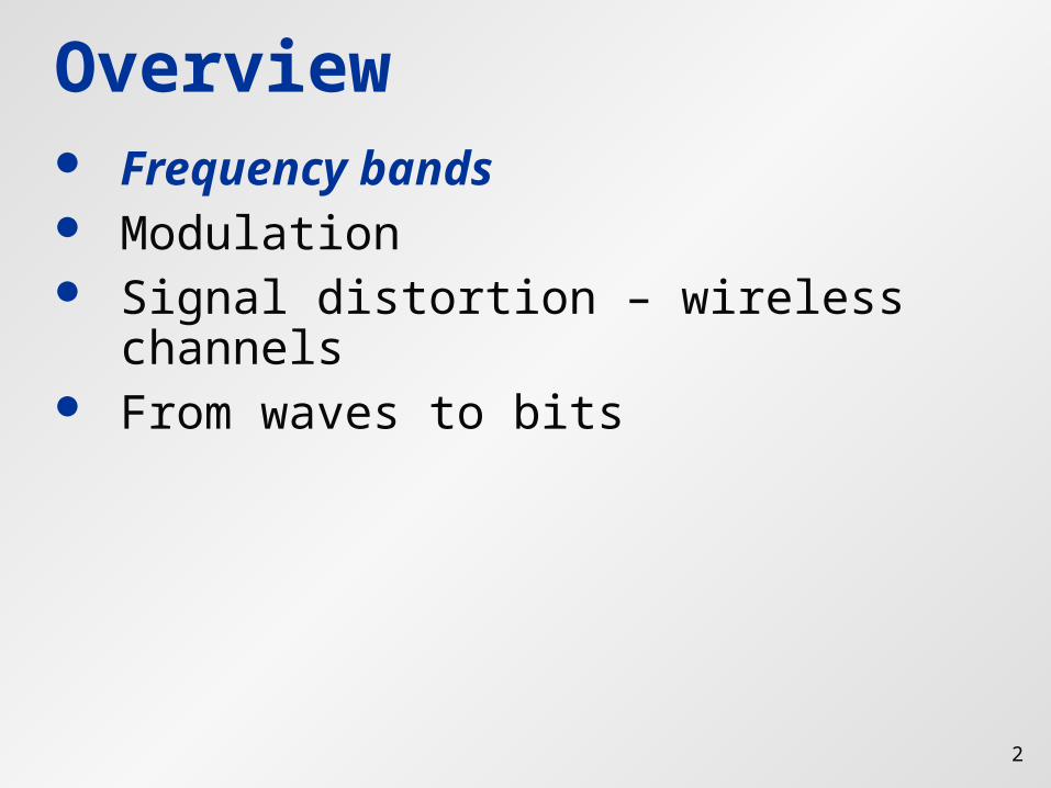
RF Spectrum
VLF = Very Low Frequency UHF = Ultra High Frequency LF = Low Frequency SHF = Super High Frequency MF = Medium Frequency EHF = Extra High Frequency HF = High Frequency UV = Ultraviolet Light VHF = Very High Frequency
1 Mm300 Hz
10 km30 kHz
100 m3 MHz
1 m300 MHz
10 mm30 GHz
100 m3 THz
1 m300 THz
visible lightVLF LF MF HF VHF UHF SHF EHF infrared UV
optical transmissioncoax cabletwisted pair
© Jochen Schiller, FU Berlin
4
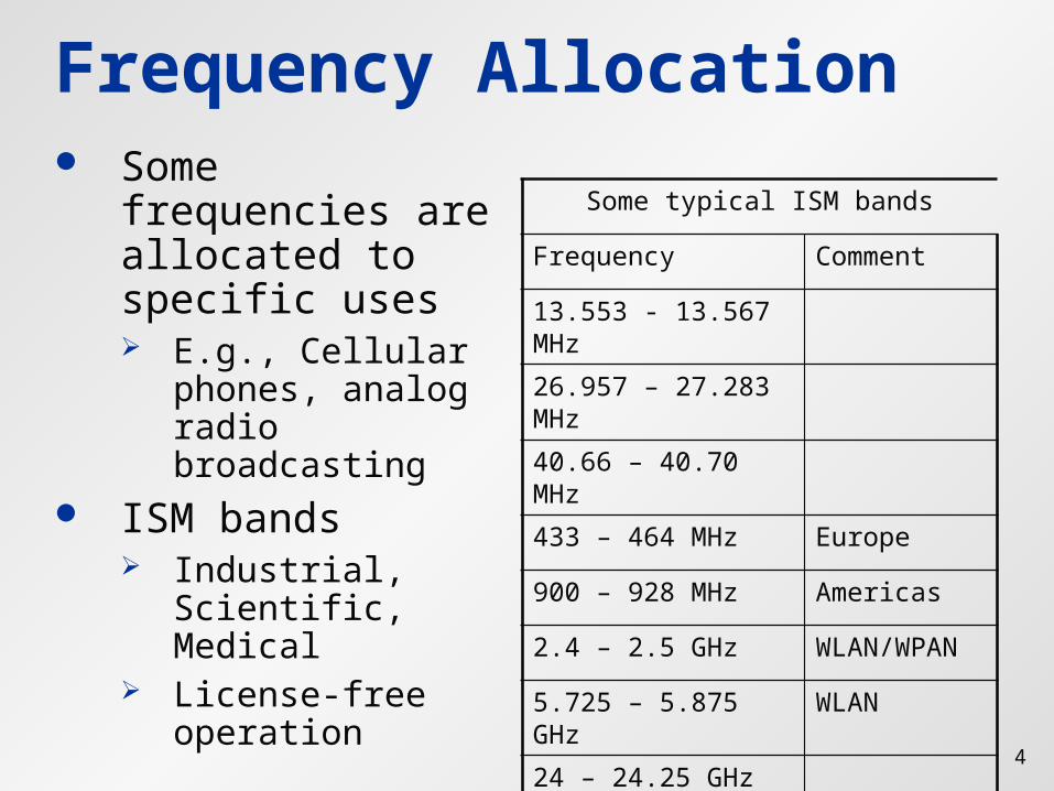
Frequency Allocation Some frequencies
are allocated to specific uses E.g., Cellular
phones, analog radio broadcasting
ISM bands Industrial,
Scientific, Medical License-free
operation
Some typical ISM bands
Frequency Comment
13.553 - 13.567 MHz26.957 – 27.283 MHz40.66 – 40.70 MHz
433 – 464 MHz Europe
900 – 928 MHz Americas
2.4 – 2.5 GHz WLAN/WPAN
5.725 – 5.875 GHz WLAN
24 – 24.25 GHz
5
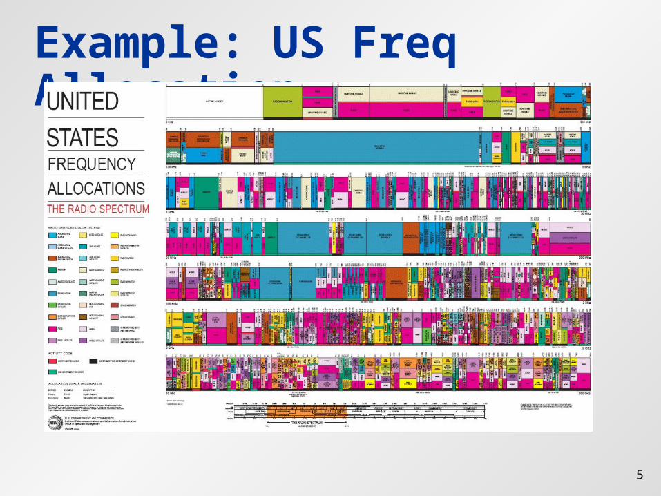
Example: US Freq Allocation
6
Overview Frequency bands Modulation Signal distortion – wireless channels From waves to bits
7
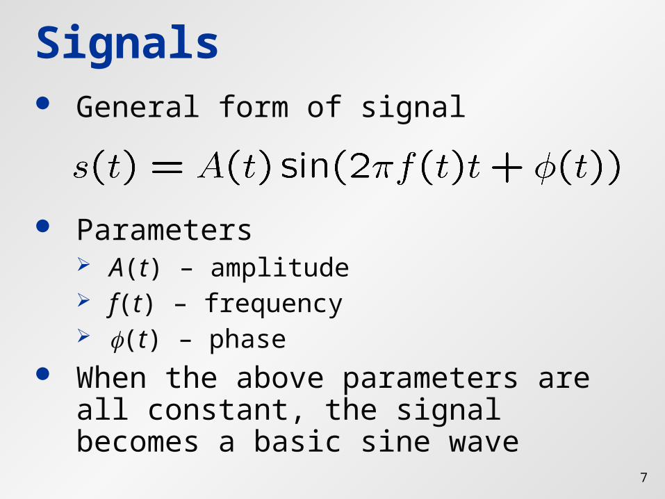
Signals General form of signal
Parameters A(t) – amplitude f(t) – frequency (t) – phase
When the above parameters are all constant, the signal becomes a basic sine wave
8
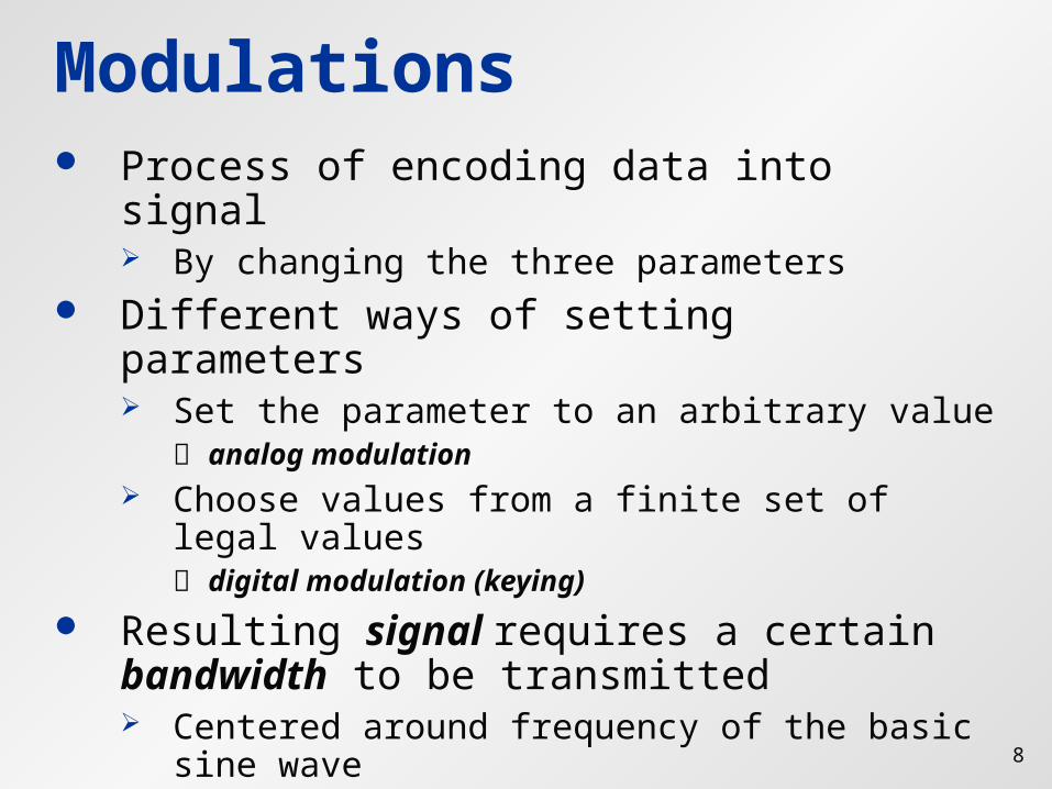
Modulations Process of encoding data into signal
By changing the three parameters Different ways of setting parameters
Set the parameter to an arbitrary value analog modulation
Choose values from a finite set of legal values digital modulation (keying)
Resulting signal requires a certain bandwidth to be transmitted Centered around frequency of the basic sine
wave
9
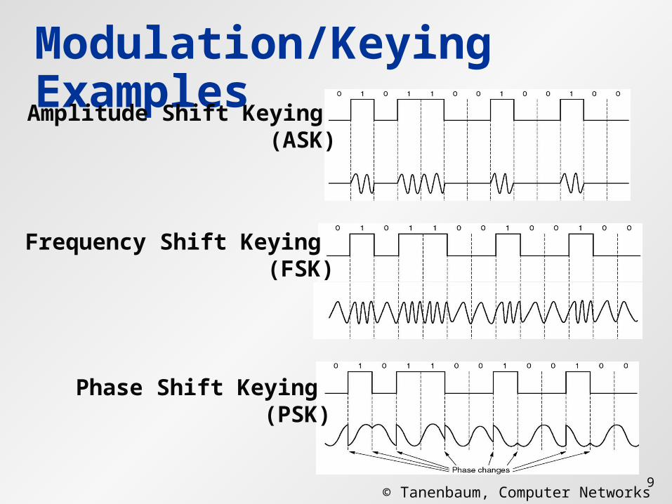
Modulation/Keying Examples
© Tanenbaum, Computer Networks
Amplitude Shift Keying (ASK)
Frequency Shift Keying (FSK)
Phase Shift Keying (PSK)
10
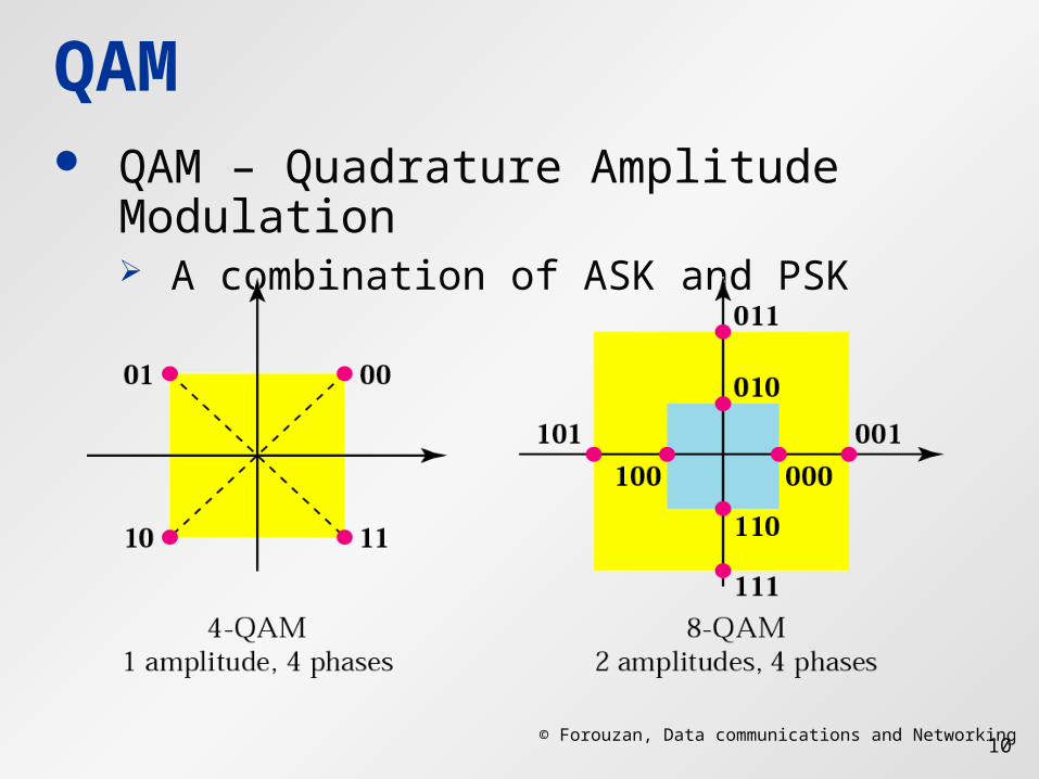
QAM QAM – Quadrature Amplitude
Modulation A combination of ASK and PSK
© Forouzan, Data communications and Networking
11
Receiver: Demodulation Receiver matches signal with
corresponding data bits Problems
Carrier synchronization: frequency may vary
Bit (symbol) boundary Frame boundary Received signal is not the transmitted
signal!
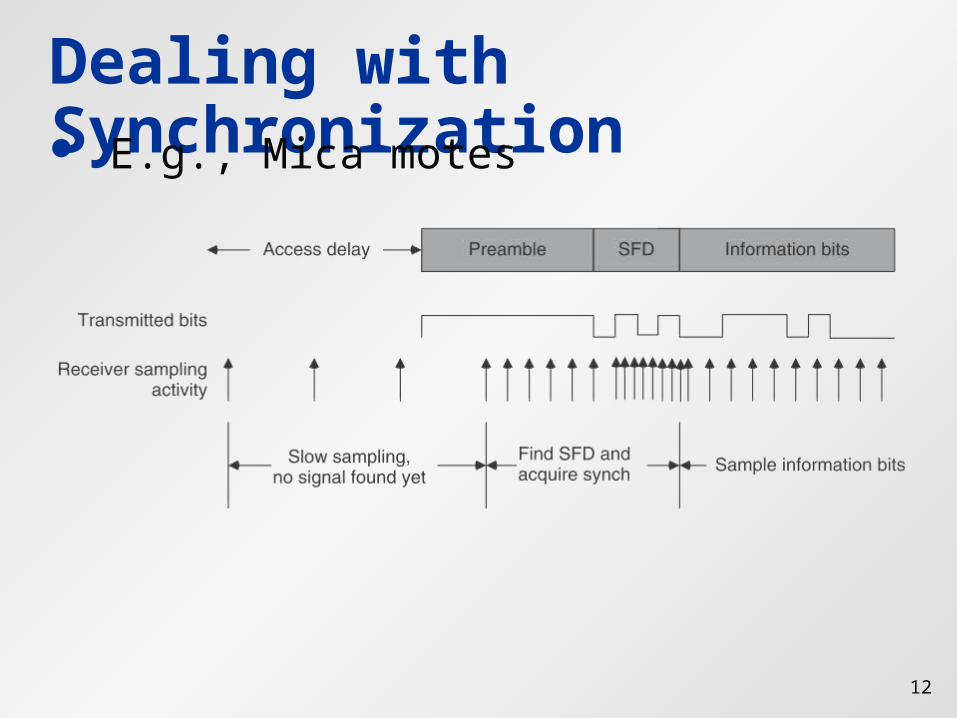
12
Dealing with Synchronization E.g., Mica motes
13
Overview Frequency bands Modulation Signal distortion – wireless
channels From waves to bits
14
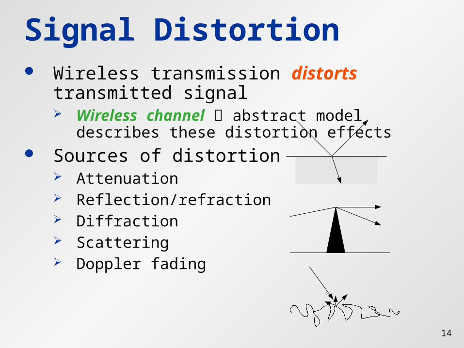
Signal Distortion Wireless transmission distorts
transmitted signal Wireless channel abstract model describes
these distortion effects Sources of distortion
Attenuation Reflection/refraction Diffraction Scattering Doppler fading
15
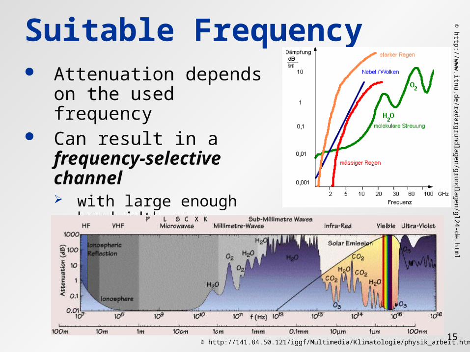
Suitable Frequency Attenuation depends
on the used frequency Can result in a
frequency-selective channel with large enough
bandwidth span
© http://w
ww
.itnu.de/radargrundlagen/grundlagen/gl24-de.html
© http://141.84.50.121/iggf/Multimedia/Klimatologie/physik_arbeit.htm
16
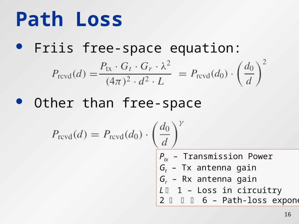
Path Loss Friis free-space equation:
Other than free-space
Ptx – Transmission PowerGt – Tx antenna gainGr – Rx antenna gainL 1 – Loss in circuitry2 6 – Path-loss exponent
17
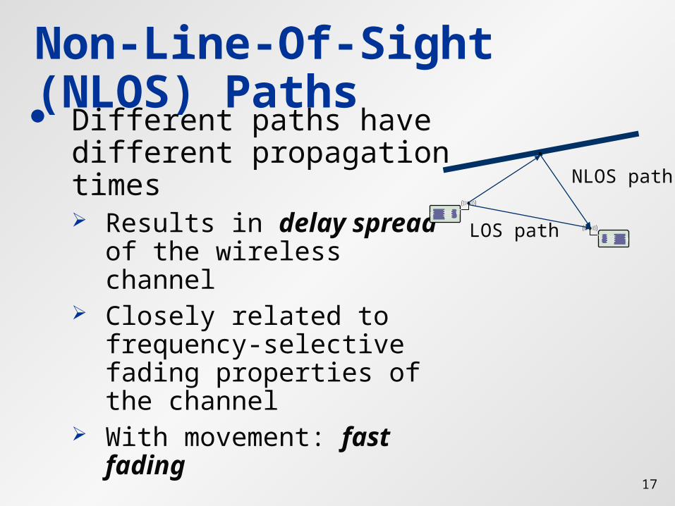
Non-Line-Of-Sight (NLOS) Paths Different paths have
different propagation times Results in delay spread
of the wireless channel Closely related to
frequency-selective fading properties of the channel
With movement: fast fading
LOS path
NLOS path
18
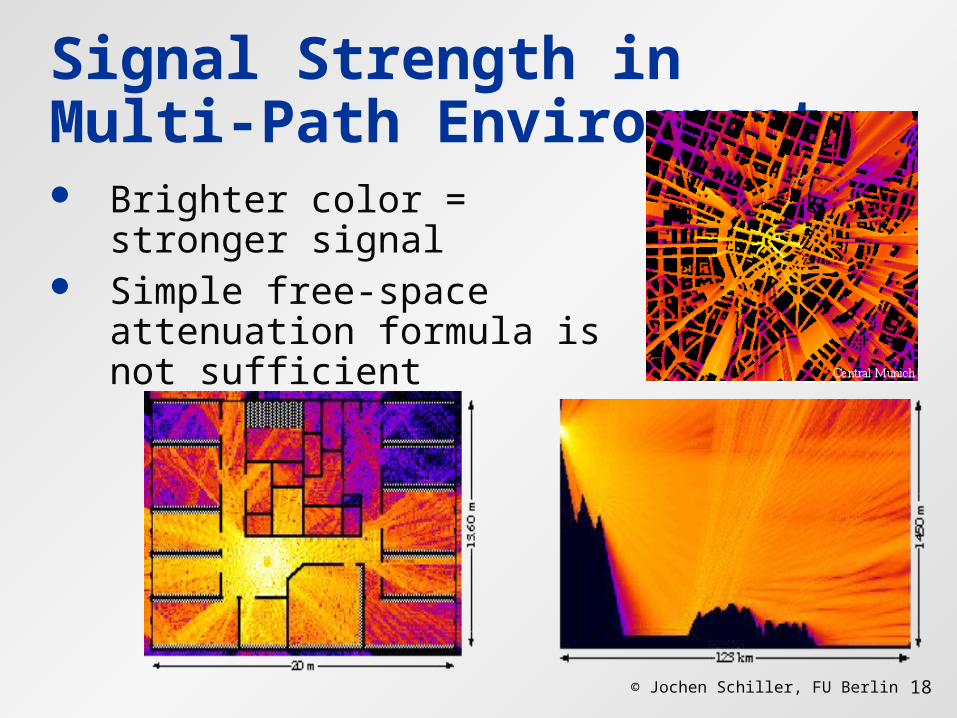
Signal Strength in Multi-Path Environment Brighter color = stronger
signal Simple free-space
attenuation formula is not sufficient
© Jochen Schiller, FU Berlin
19
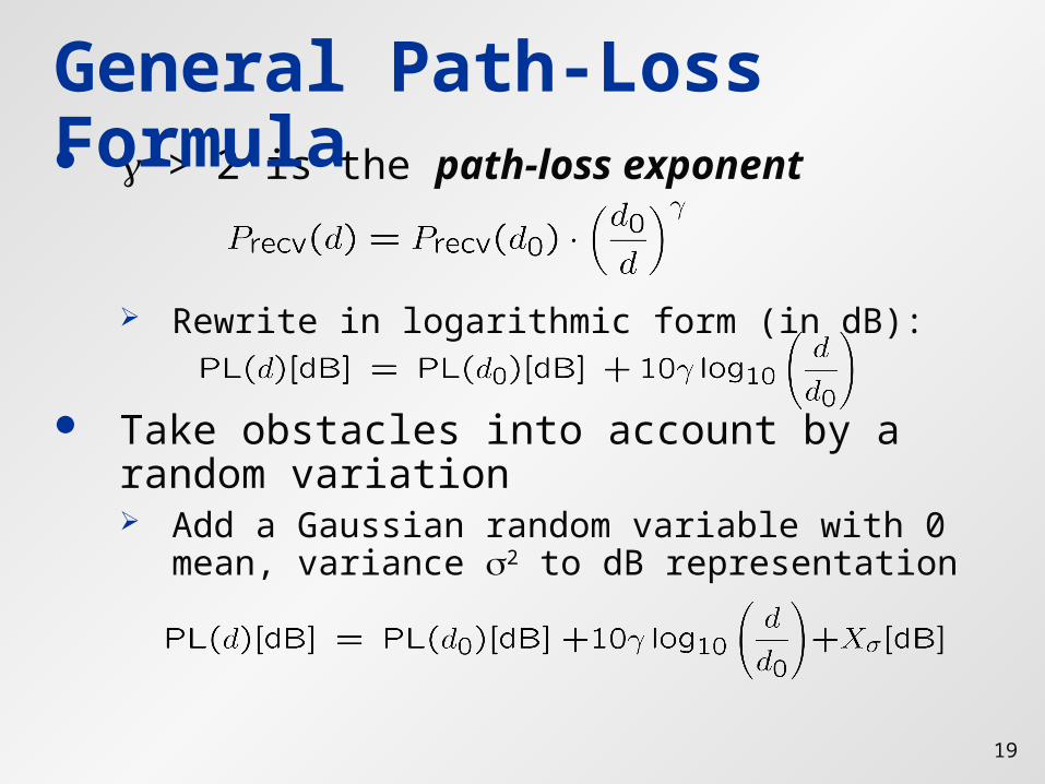
> 2 is the path-loss exponent
Rewrite in logarithmic form (in dB):
Take obstacles into account by a random variation Add a Gaussian random variable with 0 mean,
variance 2 to dB representation
General Path-Loss Formula
20
Overview Frequency bands Modulation Signal distortion – wireless channels From waves to bits
21
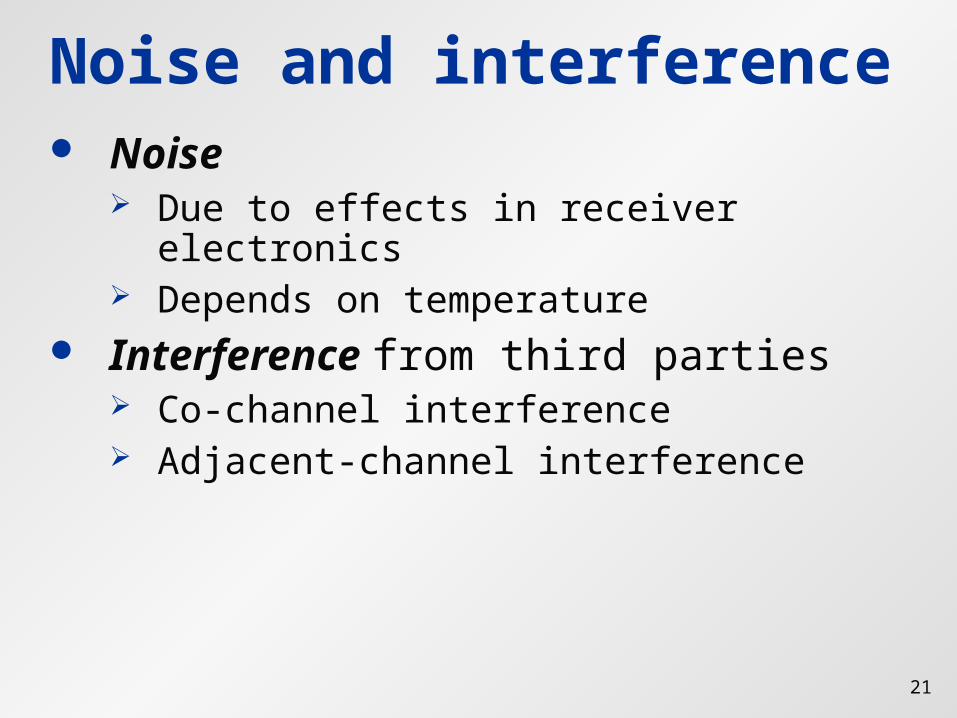
Noise and interference Noise
Due to effects in receiver electronics Depends on temperature
Interference from third parties Co-channel interference Adjacent-channel interference
22
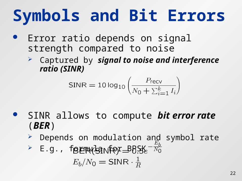
Symbols and Bit Errors Error ratio depends on signal strength
compared to noise Captured by signal to noise and
interference ratio (SINR)
SINR allows to compute bit error rate (BER) Depends on modulation and symbol rate E.g., formula for BPSK
23
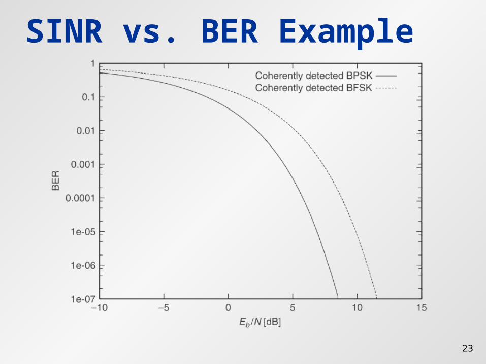
SINR vs. BER Example
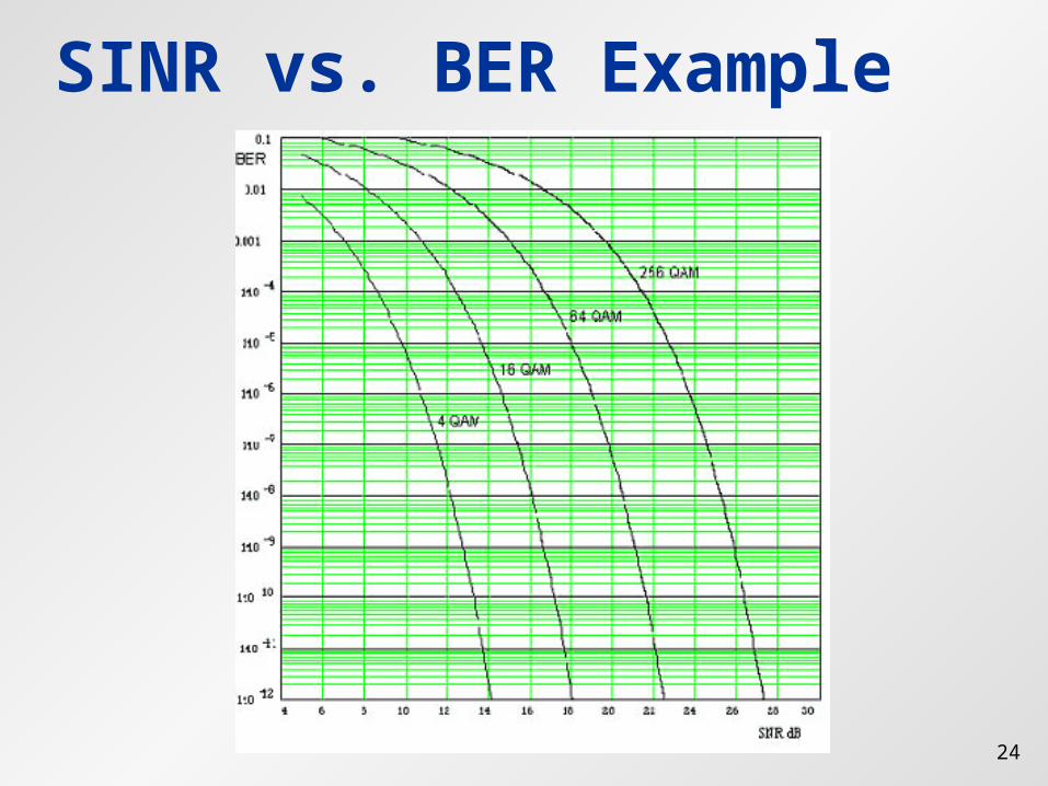
24
SINR vs. BER Example
25
Summary Wireless radio communication introduces
many uncertainties and vagaries into a communication system
Handling the unavoidable errors will be a major challenge for the communication protocols