Embed Size (px)
Citation preview

1
SE464/CS446/ECE452
Architectural Styles and PatternsInstructor:
Krzysztof Czarnecki

2
• Sources used in preparing these slides:– Lecture slides on Architecture by David Garlan, see
http://www-2.cs.cmu.edu/afs/cs/academic/class/17655-s02/www/
– Lecture slides on Architecture by Marc Roper and Murray Wood, see https://www.cis.strath.ac.uk/teaching/ug/classes/52.440/
– Lecture slides by Ian Sommerville, Software Engineering, 6th edition– M. Shaw and D. Garlan. Software Architecture: Perspectives on a
Emerging Discipline. Prentice Hall, Englewood Cliffs, NJ, 1996– F. Buschmann, R. Meunier, H. Rohnert, P. Sommerlad, and M. Stal.
Pattern-Oriented Software Architecture. A System of Patterns. John Wiley & Sons Ltd., Chichester, UK, 1996
3
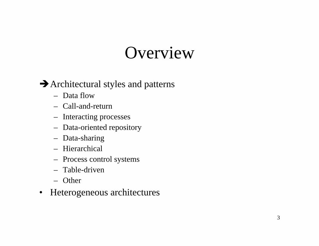
OverviewArchitectural styles and patterns– Data flow– Call-and-return– Interacting processes– Data-oriented repository– Data-sharing– Hierarchical– Process control systems– Table-driven– Other
• Heterogeneous architectures
4
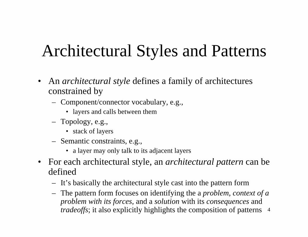
Architectural Styles and Patterns• An architectural style defines a family of architectures
constrained by– Component/connector vocabulary, e.g.,
• layers and calls between them– Topology, e.g.,
• stack of layers– Semantic constraints, e.g.,
• a layer may only talk to its adjacent layers
• For each architectural style, an architectural pattern can be defined– It’s basically the architectural style cast into the pattern form– The pattern form focuses on identifying the a problem, context of a
problem with its forces, and a solution with its consequences and tradeoffs; it also explicitly highlights the composition of patterns

5
Describing an Architectural Style• Software architectures are represented as graphs where
nodes– represent components,
• procedures• modules• processes• tools• databases• …
– and edges represent connectors.• procedure calls• event broadcasts• database queries• pipes• …

6
Determining an architectural style
• We can understand what a style is by answering the following questions.– What is the structural pattern (i.e., components,
connectors, constraints)?– What is the underlying computational model?– What are the essential invariants of the style?– What are some common examples of its use?– What are the advantages and disadvantages of using
that style?– What are some of the common specializations of that
style?
7
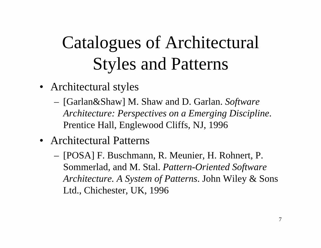
Catalogues of Architectural Styles and Patterns
• Architectural styles– [Garlan&Shaw] M. Shaw and D. Garlan. Software
Architecture: Perspectives on a Emerging Discipline. Prentice Hall, Englewood Cliffs, NJ, 1996
• Architectural Patterns– [POSA] F. Buschmann, R. Meunier, H. Rohnert, P.
Sommerlad, and M. Stal. Pattern-Oriented Software Architecture. A System of Patterns. John Wiley & Sons Ltd., Chichester, UK, 1996

8
Taxonomy of Architectural Styles
• Data flow• Call-and-return• Interacting processes• Data-oriented repository• Data-sharing• Hierarchical• …

9
“Pure” Form of Styles
• When we introduce a new style, we will typically first examine its “pure” form.– Pure data flow styles (or any other architectural style)
are rarely found in practice– Systems in practice
• Regularly deviate from the academic definitions of these systems
• Typically feature many architectural styles simultaneously– As an architect you must understand the “pure” styles
to understand the strength and weaknesses of the style as well as the consequences of deviating from the style

10
Overview• Architectural styles and patterns
Data flow– Call-and-return– Interacting processes– Data-oriented repository– Data-sharing– Hierarchical– Process control systems– Table-driven– Other
• Heterogeneous architectures

11
Data Flow
• A data flow system is one in which:– The availability of data controls the computation– The structure of the design is determined by the orderly
motion of data from component to component– The pattern of data flow is explicit– This is the only form of communication between
components• There are variety of variations on this general
theme:– How control is exerted (e.g., push versus pull)– Degree of concurrency between processes– Topology

12
Data Flow• Components: Data Flow Components
– Interfaces are input ports and output ports– Input ports read data; output ports write data– Computational model: read data from input ports, compute, write
data to output ports• Connectors: Data Streams
– Uni-directional• Usually asynchronous, buffered
– Interfaces are reader and writer roles– Computational model: transport data from writer roles to reader
roles• Systems
– Arbitrary graphs– Computational model: functional composition

13
Patterns of Data Flow in Systems
• Data can flow in arbitrary patterns
• Primarily we are interested in linear data flow patterns
• ...or in simple, constrained cyclical patterns...

14
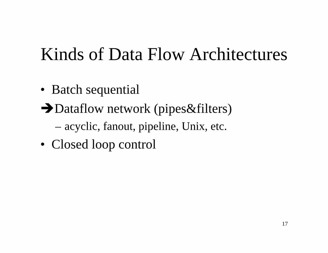
Kinds of Data Flow Architectures
Batch sequential• Dataflow network (pipes&filters)
– acyclic, fanout, pipeline, Unix, etc.• Closed loop control

15
Characteristics of Batch Sequential Systems
• Components (processing steps) are independent programs• Connectors are some type of media - traditionally magnetic tape• Each step runs to completion before the next step begins

16
Characteristics of Batch Sequential Systems
• Historical origins– Mainframes and magnetic tape– Limited disk space– Block scheduling of CPU processing time
• Typical applications: non real-time, batch oriented computations– Transformational data analysis
• Raw data is gathered and analyzed in a step-wise, batch-oriented fashion– Business data processing
• Discrete transactions of predetermined type and occurring at periodic intervals• Creation of periodic reports based on data periodic data updates• Examples
– Payroll computations– IRS tax return computations
17
Kinds of Data Flow Architectures
• Batch sequentialDataflow network (pipes&filters)– acyclic, fanout, pipeline, Unix, etc.
• Closed loop control

18
Pipes and Filters
• Architectural pattern [style] providing a structure for systems that process a stream of data
• Each processing step is encapsulated in a filter component
• Data is passed through pipes between adjacent filters
• Recombining filters allows you to build families of related systems

19
Pipes and Filters
• Components (Filters)– Read streams of data on input producing streams of
data on output– Local incremental transformation to input stream (e.g.,
filter, enrich, change representation, etc.)– Data is processed as it arrives, not gathered then
processed– Output usually begins before input is consumed
• Connectors (Pipes)– Conduits for streams, e.g., first-in-first-out buffer– Transmit outputs from one filter to input of other

20
Pipes and Filters
• Compared to the batch-sequential style, data in the pipe&filter style is processed incrementally
• The tape of the batch sequential system, morphed into a language and operating system construct

21
Pipes and Filters
• Invariants– Filters must be independent, no shared state– Filters don’t know upstream or downstream filter
identity– Correctness of output from network must not depend on
order in which individual filters provide their incremental processing
• Common specialisations– Pipelines: linear sequence of filters– Bounded and typed pipes …
22
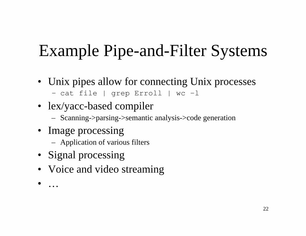
Example Pipe-and-Filter Systems
• Unix pipes allow for connecting Unix processes– cat file | grep Erroll | wc -l
• lex/yacc-based compiler– Scanning->parsing->semantic analysis->code generation
• Image processing– Application of various filters
• Signal processing• Voice and video streaming• …
23
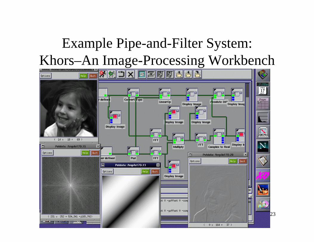
Example Pipe-and-Filter System:Khors–An Image-Processing Workbench

24
Example Pipe-and-Filter System
• Telemetry Data Collection Systems– Receives telemetry stream, decom frames,
applies coefficients, stores data

25
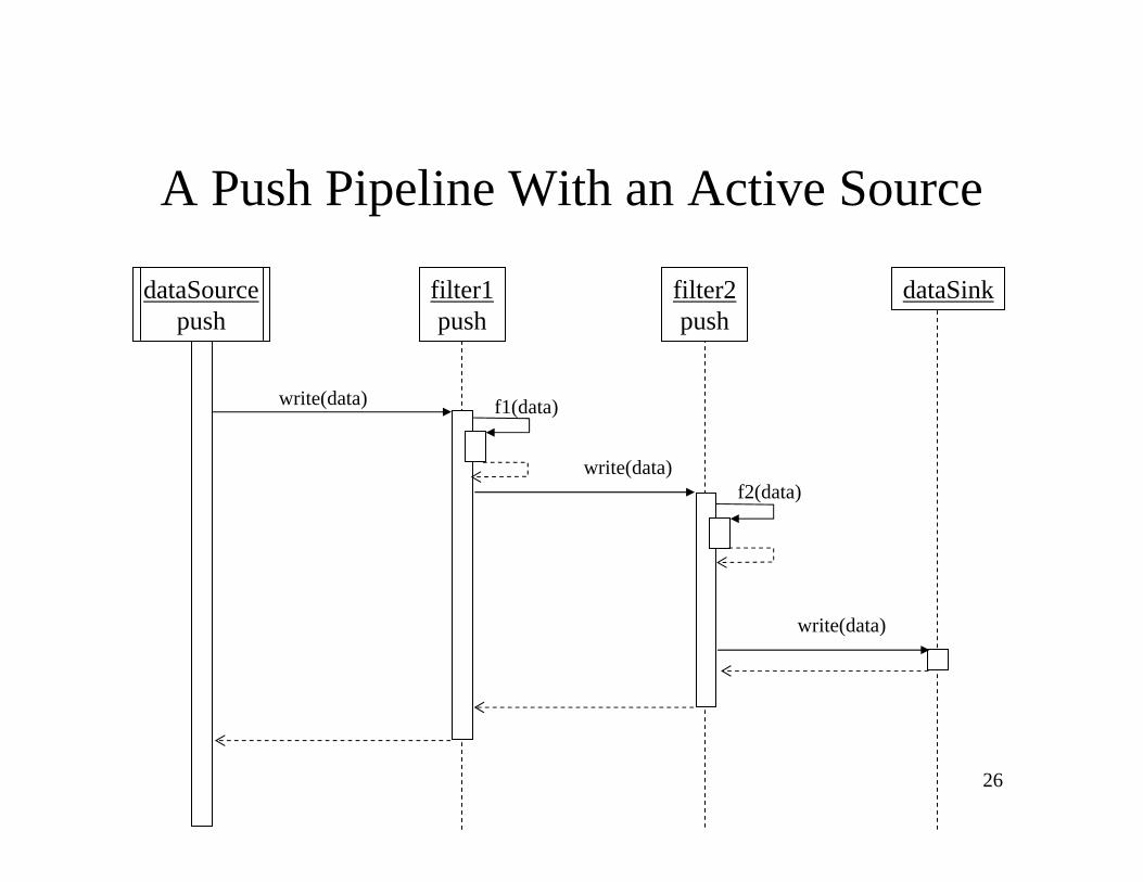
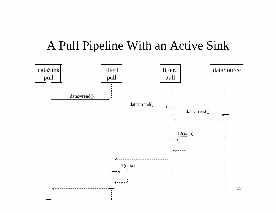
Data Pulling and Data Pushing• What is the force that makes the data flow?• Four choices:
– Push: data source pushes data in a downstream direction– Pull: data sink pulls data from an upstream direction– Push/pull: a filter is actively pulling data from a stream,
performing computations, and pushing the data downstream– Passive: don’t do either, act as a sink or source for data
• Combinations may be complex and may make the “plumber’s” job more difficult– if more than one filter is pushing/pulling, synchronization is
needed
26
A Push Pipeline With an Active Source
filter1push
dataSink
write(data)
write(data)
filter2push
f1(data)
f2(data)
write(data)
dataSourcepush
27
A Pull Pipeline With an Active Sink
dataSinkpull
filter1pull
dataSource
data:=read()
filter2pull
f1(data)
f2(data)
data:=read()data:=read()

28
A Mixed Push-pull Pipeline With Pasive Source and Sink
dataSink filter1pull/push
dataSourcefilter2pull
f1(data)
f2(data)
data:=read()data:=read()
write(data)

29
A Pipeline With Active Filters and Synchronizing Buffering Pipes
dataSource filter1pull/push
dataSink
write()
f2(data)
bufferingPipe
filter2pull/push
data:=read()
f1(data)
f1(data)
data:=read()
write()
data:=read()
data:=read()
write()
1. filter 1 pulls data from source
2. filter 2 starts to read but suspends
3. filter 1 pushes result to pipe
4. filter 2 continues since data in pipe
5. filter 2 sends result to data sink
6. filter 1 suspends since filter 2 not waiting
7. filter 2 reads data, releases filter 1
30
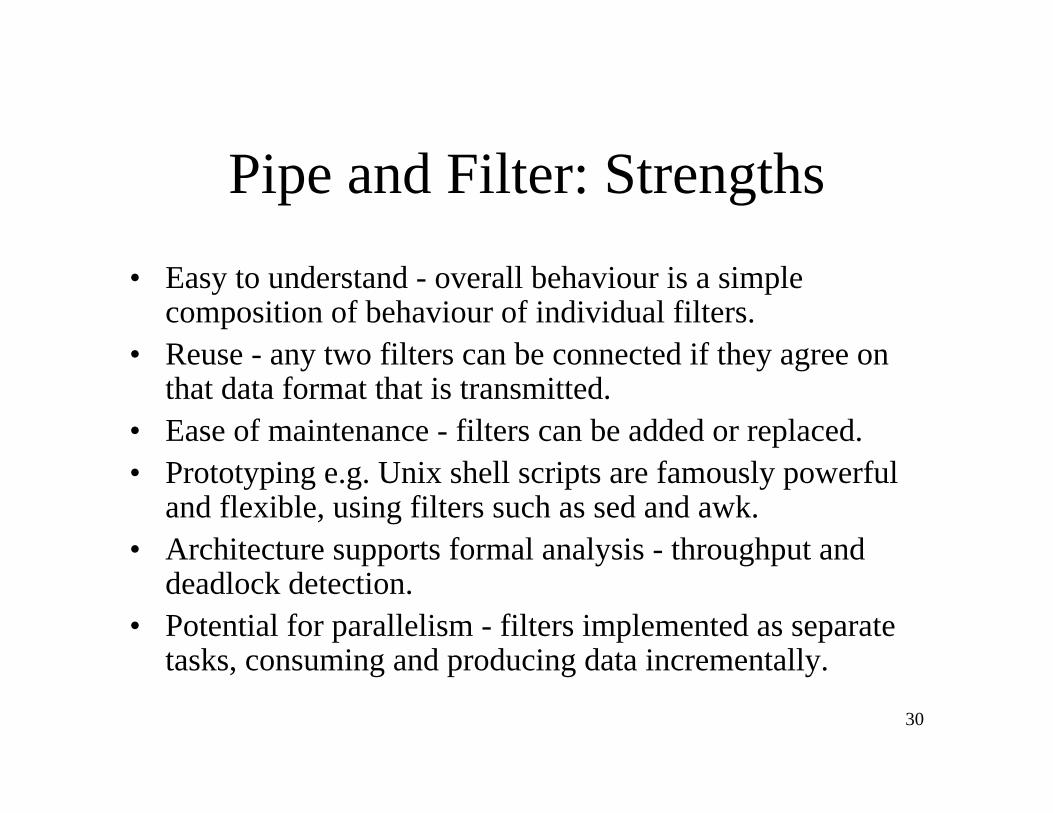
Pipe and Filter: Strengths• Easy to understand - overall behaviour is a simple
composition of behaviour of individual filters.• Reuse - any two filters can be connected if they agree on
that data format that is transmitted.• Ease of maintenance - filters can be added or replaced.• Prototyping e.g. Unix shell scripts are famously powerful
and flexible, using filters such as sed and awk.• Architecture supports formal analysis - throughput and
deadlock detection.• Potential for parallelism - filters implemented as separate
tasks, consuming and producing data incrementally.
31
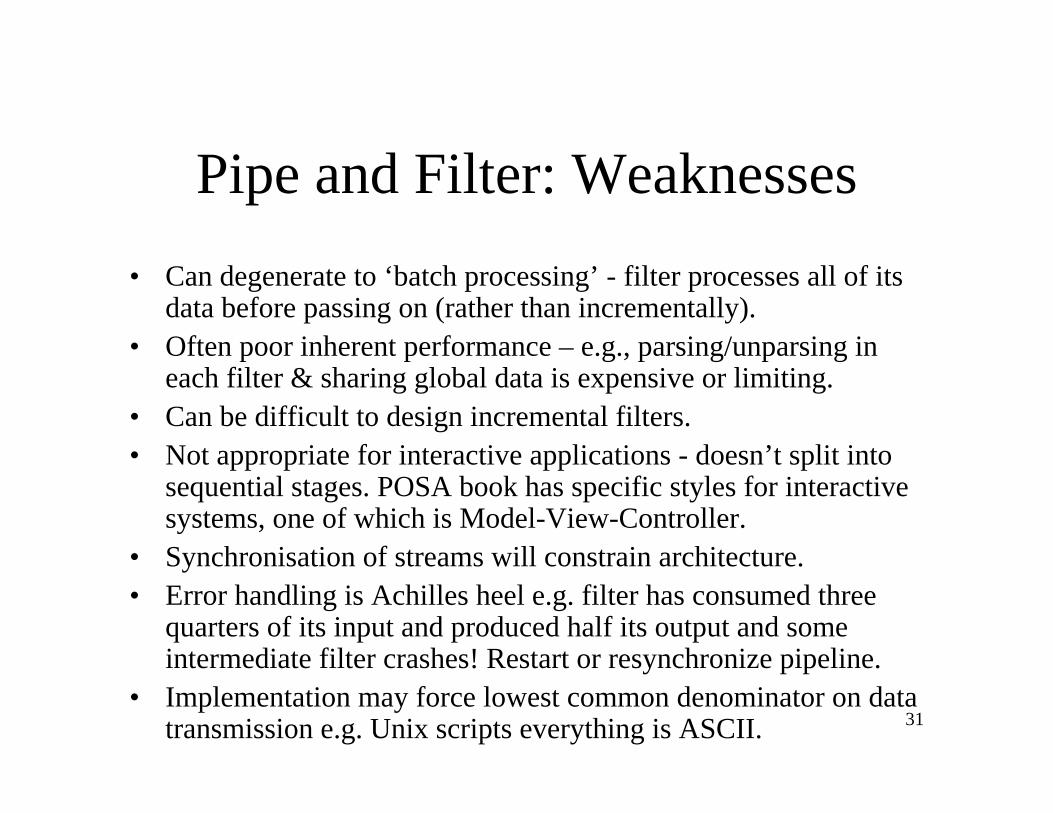
Pipe and Filter: Weaknesses• Can degenerate to ‘batch processing’ - filter processes all of its
data before passing on (rather than incrementally).• Often poor inherent performance – e.g., parsing/unparsing in
each filter & sharing global data is expensive or limiting.• Can be difficult to design incremental filters.• Not appropriate for interactive applications - doesn’t split into
sequential stages. POSA book has specific styles for interactivesystems, one of which is Model-View-Controller.
• Synchronisation of streams will constrain architecture.• Error handling is Achilles heel e.g. filter has consumed three
quarters of its input and produced half its output and some intermediate filter crashes! Restart or resynchronize pipeline.
• Implementation may force lowest common denominator on data transmission e.g. Unix scripts everything is ASCII.

32
Pipe-and-Filter vs. Batch Sequential
• Both decompose the task into a fixed sequence of computations (components) interacting only through data passed from one to another
• fine grained• results starts processing• localized input• concurrency possible• interactive awkward but
possible
• course grained• high latency• external access to input• no concurrency• non-interactive
Pipe-and-FilterBatch Sequential
33
Overview• Architectural styles and patterns
– Data flowCall-and-return
– Interacting processes– Data-oriented repository– Data-sharing– Hierarchical– Process control systems– Table-driven– Other
• Heterogeneous architectures
34
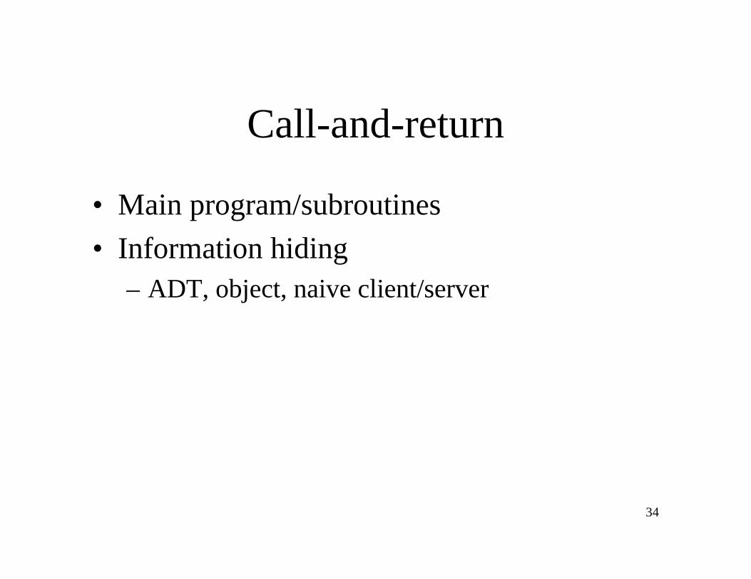
Call-and-return
• Main program/subroutines• Information hiding
– ADT, object, naive client/server

35
Main Program + Subroutine Architecture
• Classic style since 60s - pre-OO.• Hierarchical decomposition into subroutines
(Components) each solving a well defined task/function.
• Data passed around as parameters.• Main driver provides a control loop for
sequencing through subroutines.

36
Data Abstraction / Object Oriented
• Widely used architectural style• Components:
– Objects or abstract data types• Connections:
– Messages or function/procedure invocations• Key aspects:
– Object preserves integrity of representation - no direct access– Representation is hidden from objects
• Variations:– Objects as concurrent tasks– Multiple interfaces for objects for objects (Java !)
• Note that Data Abstraction is different from Object-Oriented - no inheritance.

37
Object-Oriented Strengths/Weaknesses
• Strengths:– Change implementation without affecting clients (assuming
interface doesn’t change)– Can break problems into interacting agents (distributed across
multiple machine / networks).• Weaknesses:
– To interact objects must know each other’s identity (in contrast to Pipe and Filter).
– When identity changes, objects that explicitly invoke it must change (Java interfaces help though).
– Side effect problems: if A uses B and C uses B, then C effects on B can be unexpected to A (and vice-versa).
– Complex dynamic interactions – distributed functionality.

38
Overview• Architectural styles and patterns
– Data flow– Call-and-return
Interacting processes– Data-oriented repository– Data-sharing– Hierarchical– Process control systems– Table-driven– Other
• Heterogeneous architectures

39
Interacting processes
• Communicating processes– LW processes, distributed objects, …
• Event systems– implicit invocation, pure events, …

40
Event-Based, Implicit Invocation
• This architectural style (pattern) is characterised by the style of communication between components:– Rather than invoking a procedure directly or sending a message a
component announces, or broadcasts, one or more events.
• Basically, components communicate using a generalised Observer Design Pattern style of communication.
• BUT this is a different architectural style from Object-Oriented– Communications are broadcast-based and components are not
necessarily objects.

41
Implicit Invocation Example• Components register interest in an event by associating a
procedure with the event.• When the event is announced the system implicitly invokes
all procedures that have been registered for the event.• Common style for integrating tools in a shared
environment, e.g.,– Tools communicate by broadcasting interesting events– Other tools register patterns that indicate which events should be
routed to them and which method/procedure should be invoked when an event matches that pattern.
– Pattern matcher responsible for invoking appropriate methods when each event is announced.

42
Implicit Invocation Example
• Examples:– Editor announces it has finished editing a
module, compiler registers for such announcements and automatically re-compiles module.
– Debugger announces it has reached a breakpoint, editor registers interest in such announcements and automatically scrolls to relevant source line.

43
Implicit Invocation
• Components– Modules whose interfaces provide a collection
of procedures/methods and a set of events that it may announce
• Connectors– Bindings between event announcements and
procedure/method calls– Traditional procedure/method calls (to bypass
implicit invocation)

44
Implicit Invocation
• Invariants– Announcers of events do not know which components
will be affected by those events– Components cannot make assumptions about ordering
of processing, or what processing will occur as a result of their events
• Common Examples (Shaw and Garlan textbook)– Programming environment tool integration– User interfaces - Model-View-Controller– Syntax-directed editors to support incremental semantic
checking

45
Implicit Invocation
• Strengths– Strong support for reuse - plug in new
components by registering it for events– Maintenance - add and replace components
with minimum affect on other components in the system.

46
Implicit Invocation
• Weaknesses– Loss of control
• when a component announces an event, it has no idea what components will respond to it
• cannot rely on order that these components will be invoked• cannot tell when they are finished
– Ensuring correctness is difficult because it depends on context in which invoked. Unpredictable interactions.
– Sharing data - see the Observer Design Pattern• Hence explicit invocation is usually provided as
well as implicit invocation. In practice architectural styles are combined.

47
Model-View-Controller

48
Model-View-Controller• A decomposition of an interactive system into three components:
– A model containing the core functionality and data,– One or more views displaying information to the user, and– One or more controllers that handle user input.
• A change-propagation mechanism (i.e., observer) ensures consistency between user interface and model, e.g.,
– If the user changes the model through the controller of one view, the other views will be updated automatically
• Sometimes the need for the controller to operate in the context of a given view may mandate combining the view and the controller into one component
• The division into the MVC components improves maintainability

49
Model-View-Controller
model
view1 controller1 view2 controller2 view3

50
Overview• Architectural styles and patterns
– Data flow– Call-and-return– Interacting processes
Data-oriented repository– Data-sharing– Hierarchical– Process control systems– Table-driven– Other
• Heterogeneous architectures
51
Data-Oriented Repository
• Transactional databases– True client/server
• Blackboard• Modern compiler

52
Repositories / Data Centred
• Characterised by a central data store component representing systems state and a collection of independent components that operate on the data store.
• Connections between data store and external components vary considerably in this style:– Transactional databases: Incoming stream of
transactions trigger processes to act on data store. Passive.
– Blackboard architecture: Current state of data store triggers processes. Active.

53
Examples of Repository Architectures
• Information systems• Programming environments• Graphical editors• AI knowledge bases• Reverse engineering systems• Variations: Data structure in memory or on
disk, concurrency, triggering

54
Blackboard• Characteristics: cooperating ‘partial solution solvers’
collaborating but not following a pre-defined strategy.• Current state of the solution stored in the blackboard.• Processing triggered by the state of the blackboard.
Blackboard(shared data)
KnowledgeSource 6
KnowledgeSource 5
KnowledgeSource 4
KnowledgeSource 3
KnowledgeSource 2
KnowledgeSource 1

55
Examples of Blackboard Architectures
• Problems for which no deterministic solution strategy is known, but many different approaches (often alternative ones) exist and are used to build a partial or approximate solution.– AI: vision, speech and pattern recognition (see POSA
case study)– Modern compilers act on shared data: symbol table,
abstract syntax tree (see Garlan and Shaw case study)

56
Advantages of Repositories
• Efficient way to store large amounts of data.
• Sharing model is published as the repository schema.
• Centralized management for– backup,– security and– concurrency control

57
Disadvantages of Repositories
• Must agree on a data model a priori• Data evolution is expensive• Difficult to distribute data

58
Overview• Architectural styles and patterns
– Data flow– Call-and-return– Interacting processes– Data-oriented repository
Data-sharing– Hierarchical– Process control systems– Table-driven– Other
• Heterogeneous architectures

59
Data-sharing
• Compound documents• Hypertext• Fortran COMMON• LW processes

60
Overview• Architectural styles and patterns
– Data flow– Call-and-return– Interacting processes– Data-oriented repository– Data-sharing
Hierarchical– Process control systems– Table-driven– Other
• Heterogeneous architectures
61
Hierarchical
• Layered– Interpreter– Tiered

62
Layered Systems
• “A layered system is organised hierarchically, each layer providing service to the layer above it and serving as a client to the layer below.” (Garlan and Shaw)
• Each layer collects services at a particular level of generality / application specificity.
• In a pure layered system: Layers are hidden to all except adjacent layers.
63
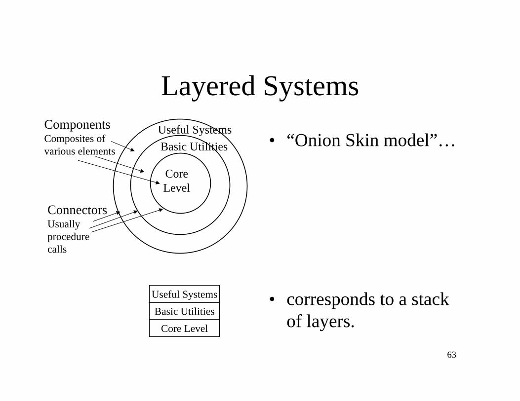
Layered Systems
• “Onion Skin model”…
• corresponds to a stack of layers.
ComponentsComposites ofvarious elements
ConnectorsUsuallyprocedurecalls
Useful SystemsBasic Utilities
Core Level
CoreLevel
Basic UtilitiesUseful Systems

64
Layered Systems
C_3.1 C_3.2 C_3.3
C_2.1 C_2.2 C_2.3
C_1.1 C_1.2 C_1.3 Layer 1
Layer 2
Layer 3
uses
1. Components within same layer interact2. Components within different layers might call each other directly

65
Hierarchical systems
• Hierarchical systems can be tree-like in general

66
Layered Systems• Applicability
– A large system that is characterised by a mix of high and low level issues, where high level issues depend on lower level ones.
• Components– Group of subtasks which implement a ‘virtual machine’ at some
layer in the hierarchy• E.g., a set of functions or classes
• Connectors– Protocols / interface that define how the layers will interact
• E.g., function calls or event sends according to some protocol
67
Layered Systems
• Invariants– Limit layer (component) interactions to adjacent layers
• in practice this may be relaxed for efficiency reasons – “layer bridging” (a layer may talk directly to some non-adjacent layers)
• Typical variant relaxing the pure style– A layer may access services of all layers below it
• Common Examples– Communication protocols: each level supports
communication at a level of abstraction, lower levels provide lower levels of communication, the lowest level being hardware communications.

68
Sample Implementation
<<interface>>Policy Service
Interface
<<interface>>Mechanism Service
Interface
MechanismLayer
PolicyLayer
UtilityLayer
Policy
Mechanism
Utility

69
Designing Error Handling Strategies
• Error can be handled in layer in which it occurred, or passed to next higher level
• Do not swamp upper layers with different error handling and many errors– Condense several error types into a general error type– Upper layers may be confronted with error they do not
understand• May require error to be transformed into an error
that the upper layer understands [portability issues?]
• Best to handle errors in layers they occur

70
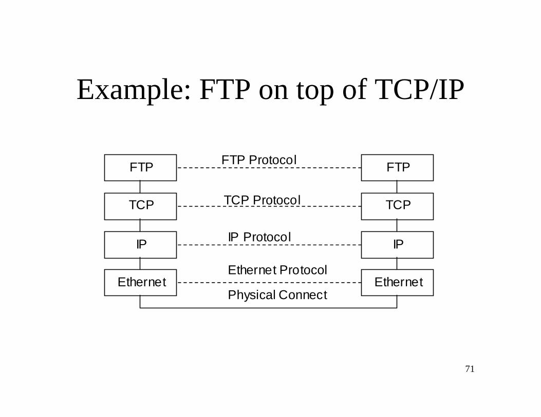
Layered System Examples• Example 1: ISO defined the OSI 7-layer architectural
model with layers: Application, Presentation, …, Data, Physical.– Protocol specifies behaviour at each level of abstraction (layer).– Each layer deals with specific level of communication and uses
services of the next lower level.• Example 2: TCP/IP is the basic communications protocol
used on the internet. POSA book describes 4 layers: ftp, tcp, ip, Ethernet. The same layers in a network communicate ‘virtually’.
• Example 3: Operating systems e.g. hardware layer, …, kernel, resource management, … user level “Onion Skin model”.
• ...
71
Example: FTP on top of TCP/IP
FTP
TCP
IP
Ethernet
FTP
TCP
IP
Ethernet
FTP Protocol
TCP Protocol
IP Protocol
Ethernet Protocol
Physical Connect
72
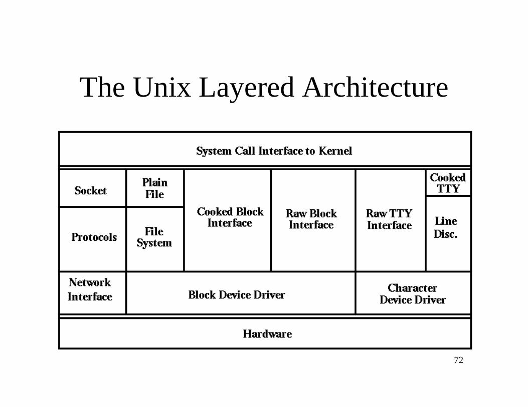
The Unix Layered Architecture

73
Layered Systems
• Strengths– Increasing levels of abstraction as we move up
through layers – partitions complex problems– Maintenance - in theory, a layer only interacts
with layers above and below. Change has minimum effect.
– Reuse - different implementations of the same level can be interchanged
– Standardisation based on layers e.g. OSI

74
Layered Systems• Weaknesses
– Not all systems are easily structured in layers (e.g., mobile robotics)
– Performance - communicating down through layers and back up, hence bypassing may occur for efficiency reasons
• Similar strengths to data abstraction / OO but with multiple levels of abstraction (e.g. well-defined interfaces, implementation hidden).
• Similar to pipelines, e.g., communication with at most one component at either side, but with richer form of communication.
• A layer can be viewed as aka “virtual machine” providing a standardized interface to the one above it
75
Interpreter
• Architecture is based on a virtual machine produced in software.
• Special kind of a layered architecture where a layer is implemented as a true language interpreter.
• Components are ‘program’ being executed, its data, the interpretation engine and its state.
• Example: Java Virtual Machine. Java code translated to platform independent bytecodes. JVM is platform specific and interprets (or compiles - JIT) the bytecodes.

76
Interpreter

77
Interpreter – More Examples
• Programming and scripting languages– Awk, Perl, …
• Rule-based systems– Prolog, Coral, …
• Micro-coded machine– Implement machine code in software
• Presentation package– Display a graph, by operating on the graph

78
Tiered Architectures
• Special kind of layered architecture for enterprise applications
• Evolution– Two Tier– Three Tier– Multi Tier

79
Two Tier Client Server Architecture Design
• Developed in the 1980s to decouple (typically form/based) user interface from the storage of data.
• Improved maintainability (changes to UI and database can be made independently); Scales up to 100 users
• See http://www.sei.cmu.edu/str/descriptions/twotier.html#512860Client tierUser System Interface+ Some ProcessingManagement
Server tierDatabase Management+ Some ProcessingManagement

80
Three Tier Client Server Architecture Design
• Emerged in the 1990s to overcome the limitations of the two tier architecture by adding an additional middle tier.
• This middle tier provides process management where business logic and rules are executed and can accommodate hundreds of users by providing generic services such as queuing, application execution, and database staging.
• An effective distributed client/server design that provides increased performance, flexibility, maintainability, reusability, and scalability, while hiding the complexity of distributed processing from the user.
• See http://www.sei.cmu.edu/str/descriptions/threetier.html

81
Three Tier Client Server Architecture Design
User System Interface
Database Management
Processing Management

82
Example of a Multi Tier Architecture: Java 2 Platform, Enterprise Edition (J2EE)

83
Overview• Architectural styles and patterns
– Data flow– Call-and-return– Interacting processes– Data-oriented repository– Data-sharing– Hierarchical
Process control systems– Table-driven– Other
• Heterogeneous architectures

84
Process-Control Architecture Style
• Suitable for applications whose purpose is to maintain specified properties of the outputs of the process at sufficiently near given reference values.
• Components– Process definition includes mechanisms for
manipulating some process variables.– Control algorithm for deciding how to
manipulate process variables.

85
Process-Control Architecture Style
• Connectors are the data flow relations for– Process Variables
– Controlled variable whose value the system is intended to control.
– Input variable that measures an input to the process.– Manipulated variable whose value can be changed by the
controller.– Set Point is the desired value for a controlled variable.– Sensors to obtain values of process variables pertinent to control.

86
Feed-Back Control System
• The controlled variable is measured and the result is used to manipulate one or more of the process variables.
87
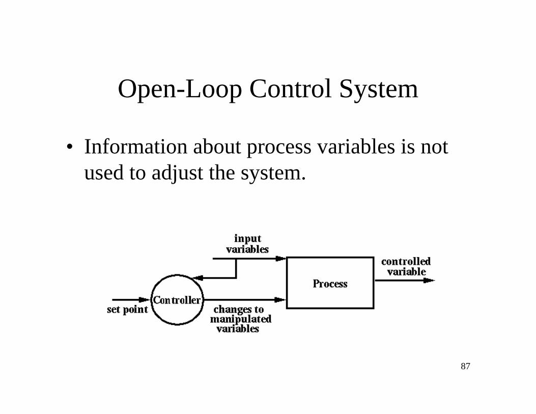
Open-Loop Control System
• Information about process variables is not used to adjust the system.

88
Process Control Examples
• Real-time system software to control:• Automobile anti-lock brakes.• Nuclear power plants• Automobile cruise-control

89
Overview• Architectural styles and patterns
– Data flow– Call-and-return– Interacting processes– Data-oriented repository– Data-sharing– Hierarchical– Process control systems
Table-driven– Other
• Heterogeneous architectures
90
Table-Driven Architecture• The logic is essentially governed by tables or data structures which are
pre-computed and then compiled into the code• Useful when we wish to reduce the run time complexity of the code by
pre-computing its appropriate behavior in data inserted into the code at compile time
• Pros/Cons– Improves performance of system– Can produce clean solutions to seemingly difficult problems– Can be hard to grasp what is going on as different events occur in unclear
orders.• Example: Yacc
– Tables are generated which determine how parsing is to be performed

91
Overview• Architectural styles and patterns
– Data flow– Call-and-return– Interacting processes– Data-oriented repository– Data-sharing– Hierarchical– Process control systems– Table-driven
Other• Heterogeneous architectures

92
Other Architectures...
• Distributed Systems:– Common organisations for multi-process systems
characterised either by topological organisation e.g. ring or star, and inter-process protocols e.g. client-server architectures.
– Broker pattern: An arrangement where decoupled components interact by remote service invocations. A broker component is responsible for coordinating communication and for transmitting results and exceptions.
93
POSA Architectural Patterns
• These were already discussed:– Layers pattern– Pipes and filters pattern– Blackboard pattern– Model-view-controller pattern– Broker pattern

94
POSA Architectural Patterns for Adaptable Systems
• Microkernel pattern– An arrangement that separates a minimal functional core from
extended functionality and customer-specific parts.– The microkernel also serves as a socket for plugging in these
extensions and coordinating their collaboration.
• Reflection pattern– Organize a system into a base level performing the actual
functionality and a meta-level providing a runtime, explicit configuration model of the base level.
– The metalevel makes software self-aware by allowing to inspect and possibly reconfigure itself through the metalevel

95
Overview• Architectural styles and patterns
– Data flow– Call-and-return– Interacting processes– Data-oriented repository– Data-sharing– Hierarchical– Process control systems– Table-driven– Other
Heterogeneous architectures
96
Heterogeneous Architectures• In practice the architecture of large-scale system is a
combination of architectural styles:– (‘Hierarchical heterogeneous’) A Component in one style may
have an internal style developed in a completely different style(e.g, pipe component developed in OO style, implicit invocation module with a layered internal structure, etc.)
– (‘Locational heterogeneous’) Overall architecture at same level is a combination of different styles (e.g., repository (database) andmain-program subroutine, etc.)Here individual components may connect using a mixture of architectural connectors - message invocation and implicit invocation.
– (‘Perspective heterogeneous’) Different architecture in different perspectives (e.g., structure of the logical view, structure of the physical view, etc.)
97
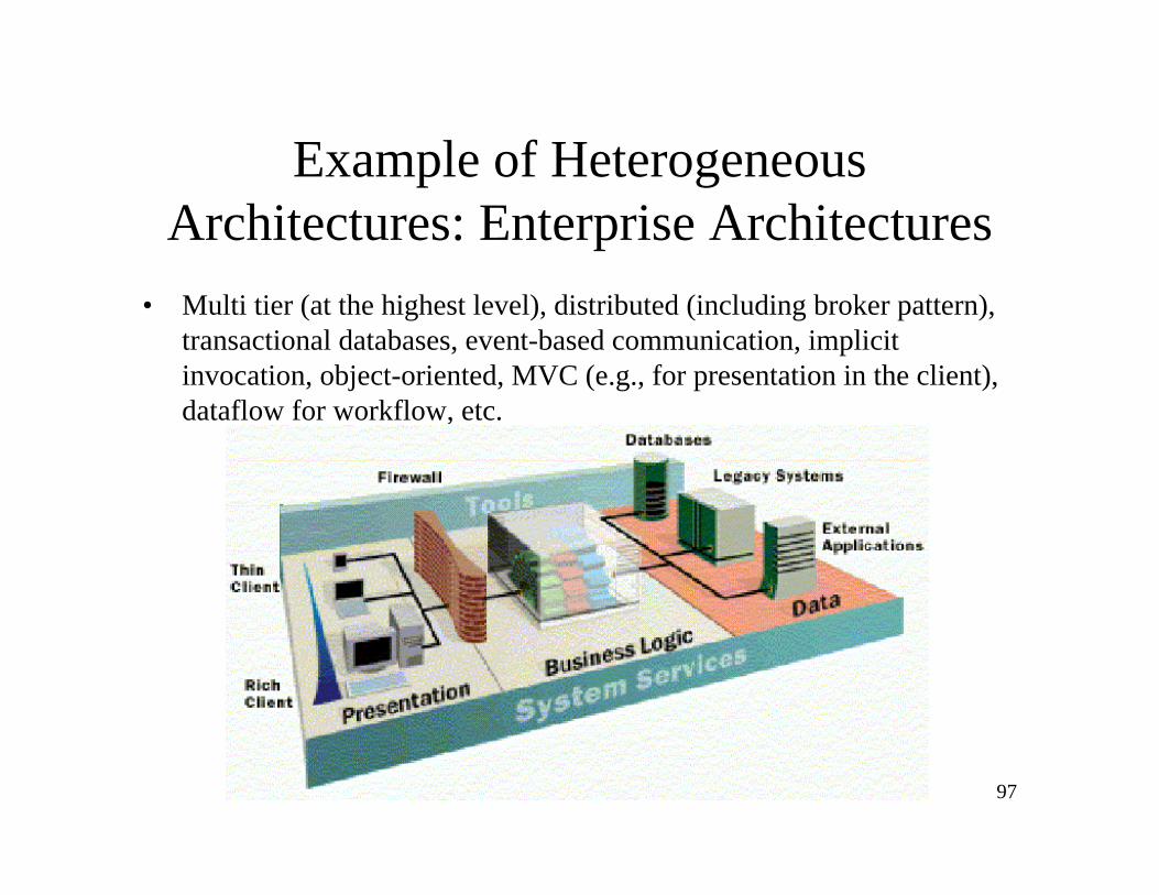
Example of Heterogeneous Architectures: Enterprise Architectures
• Multi tier (at the highest level), distributed (including broker pattern), transactional databases, event-based communication, implicit invocation, object-oriented, MVC (e.g., for presentation in the client), dataflow for workflow, etc.