Embed Size (px)
Citation preview

Real-Time Imaging 6, 313±324 (2000)doi:10.1006/rtim.1999.0191, available online at http://www.idealibrary.com on
Architectural Issues on Vision-BasedAutomatic Vehicle Guidance: TheExperience of the ARGO Project
This paper discusses the main architectural issues of a challenging application of real-timeimage processing: the vision-based automatic guidance of road vehicles. Two algorithmsfor lane detection and obstacle localization, currently implemented on the ARGO
autonomous vehicle developed at the University of Parma, are used as examples to compare twodi�erent computing engines Ð a massively parallel special-purpose SIMD architecture and ageneral-purpose system Ð while future trends in this ®eld are proposed, based on the experienceof the ARGO project.
# 2000 Academic Press
Alberto Broggi1, Massimo Bertozzi2 and Alessandra Fascioli2
1Dipartimento di Informatica e Sistemistica, UniversitaÁ di Pavia, I-27100 Pavia, Italy,E-mail: [email protected]
2Dipartimento di Ingegneria dell'Informazione, UniversitaÁ di Parma, I-43100 Parma, Italy,E-mail: {bertozzi, fascal}@CE.UniPR.IT
Introduction
A great deal of di�erent sensors exploiting di�erenttechnologies, such as radars, lasers, sonars and bumpers,have been used on autonomous vehicles and robots ingeneral to sense the surrounding environment, butpassive sensors like cameras can o�er prominentadvantages such as the possibility of acquiring data ina non-invasive way, namely without altering theenvironment. In contrast, the use of active sensorsinvolves the measure of the alteration of signals emittedby the sensors themselves, with the following two mainadvantages:
(1) ®rst, they can measure quantities in a more directway than vision. As an example, a Doppler radarcan directly measure the relative movementsbetween an object and the viewer, while vision can
1077-2014/00/080313+12 $35.00/0
detect movement only as a result of a complexprocessing of image sequences;
(2) a second advantage is given by the considerablylower amount of acquired data, thus requiring lessperforming computing engines.
Active sensors are extremely powerful, but there areapplications in which only vision can be successfullyemployed. In many indoor applications, such as thenavigation of autonomous robots in unknown settings,vision can be greatly helped by active sensors in the taskof recognition of objects, detection of the free-space, orchecking for some speci®c objects' characteristics.Unfortunately, in case more than one robot is movinginto the same environment, their active sensors mayinterfere with each other and cause problems. Theproblem gets even greater in an outdoor unstructuredenvironment, in which a large number of vehicles could
# 2000 Academic Press

314 A. BROGGIETAL.
be moving simultaneously. Hence, in the cases in whicha massive and wide-spread use of autonomous sensingagents is envisaged, the use of passive sensors, such ascameras, is greatly preferred to invasive methods ofperceiving the environment, which could lead to anunacceptable pollution of the environment. These arecases in which vision becomes of paramount impor-tance.
The task of automatic vehicle guidance in outdoorenvironments must face other key problems intrinsic tothe use of vision.
(1) Contrary to indoor settings, outdoor environmentscannot rely on structured information. This isparticularly true in the automotive ®eld, wherevehicles can move along roads with di�erentcharacteristics, and the integration of speci®cinfrastructures would be extremely expensive andprohibitive: an automatic vehicle should be able tonavigate using standard road signs, withoutrequiring further additional infrastructures.
(2) More than other applications, automatic vehicleguidance requires fast processing, since themaximum vehicle speed is proportional to theprocessing rate (for example, a processing rate of25 frames/s allows to provide the control signals forautonomous steering every 40ms, which isequivalent to one re®nement on the steering wheelposition for every meter when the vehicle drives at100 km/h). For this purpose, the main problem,intrinsic to the processing of images, is the largeamount of data, and thus of computation involved.Therefore, speci®c computer architectures andprocessing techniques must be considered in orderto achieve real-time performance. Nevertheless,since the success of such automatic systems istightly related to their cost, the computing enginescannot be based on expensive processors. Thus,either o�-the-shelf components or ad hoc dedicatedlow-cost solutions must be considered.
In addition, the processing of images acquired by acamera installed on a moving vehicle in a non-structuredoutdoor environment su�ers from some other majorproblems. Contrary to indoor applications, whererobots move in controlled environments, the automotive®eld no assumptions can be made on key parameters,such as, for example, the illumination or the contrast ofthe scene, which are directly measured by the visionsensor. Hence, the subsequent processings must berobust enough to tolerate their changes and to adapt
both to di�erent road conditions, such as sun (highbrightness and contrast due to shadows), rain (extremelyhigh contrast due to re¯ections), fog (low contrast), andto their dynamic changes, such as transitions from sunto shadows or the entrance in a tunnel. Other keyproblems, such as the robustness to camera movementsand to drifts in its calibration must be addressed as well.
This paper is organized as follows: the second sectionaddresses the problem of automatic vehicle guidanceand presents the solutions implemented on the ARGOautonomous test vehicle; the third section describes thearchitectural issues that were considered in the selectionof the computing engine; and the ®nal section concludesthe paper with a discussion on future trends.
Automatic Vehicle Guidance
Although extremely complex and highly demanding,computer vision is a powerful mean to sense theenvironment and has been widely employed to addressa large number of tasks for automatic vehicle guidance[7], ranging from Road Following, to Platooning (theautomatic following of a manually driven vehicle by anautomatic one), from Vehicle Overtaking, to AutomaticParking. To accomplish these tasks di�erent quantitiesmust be measured and/or patterns recognized before theclosing of the control loop, such as:
(1) the relative position of the vehicle with respect to thelane, the check for obstacles on the path or forknown road signs for Road Following;
(2) the recognition of a speci®c vehicle's characteristicsand the computation of the time-to-impact forPlatooning;
(3) the sensing of multiple lanes as well as obstacledetection for Vehicle Overtaking;
(4) the distance among already parked vehicles and thecomputation of the free-space for AutomaticParking.
Among all, the most complex and challenging taskthat has received the most insightful attention is indeedRoad Following since it comprehends several basicfunctionalities such as Lane Detection and ObstacleDetection. A more complete survey of the di�erentapproaches developed worldwide can be found in [3].
The following subsections present a brief overview ofthe two algorithms that are currently implemented onARGO, a Lancia Thema passenger car (see Figure 1)

Figure 1. The experimental vehicle ARGO.
VISION-BASEDAUTOMATIC VEHICLEGUIDANCE 315
used as a test vehicle. ARGO is equipped with a pair ofsynchronized stereo cameras to sense the environmentand an odometer to measure the vehicle speed. Thesedata are processed in order to detect obstacles andlocalize the lane ahead of the vehicle. A monitor, a led-based control panel, and a pair of stereo speaker areused to warn the driver with optic and acoustic signals incase of dangerous situations. Moreover the vehicle isequipped with autonomous steering capabilities: thesystem is able to follow the lane automatically by issuingcommands to an actuator mounted on the steeringcolumn. The driver can interact with the system througha control panel, an emergency pedal, a joystick, and akeyboard (see Figure 2).
Lane detection
In most prototype autonomous vehicles developedworldwide Road Following is based on Lane Detection:®rst the relative position of the vehicle with respect tothe lane is computed and then actuators are driven tokeep the vehicle in a safe position.
Figure 2. The computing architecture and equipment.
Thanks to the knowledge of the acquisition systemsetup and to a hypothesis of a ¯at road in front of thevehicle, from the captured image (Figure 3(a)) it ispossible to generate a new image (Figure 3(b)) in whichthe perspective e�ect has been removed. In this imagelane markings can be devised as almost vertical brightlines of constant width, surrounded by a darker region.In this case the pixels belonging to a road marking havea brightness value higher than their horizontal left andright neighbors at a given distance. Thus, the ®rst phaseof lane detection is based on the search for dark±bright±dark horizontal patterns with a speci®c size. Thebrightness value of every pixel is compared to that ofits left and right horizontal neighbors and a new gray-level image is computed, which encodes the horizontalbrightness transitions and thus the presence of lanemarkings.
Di�erent illumination conditions, such as shadows orsunny blobs, cause road markings to have di�erentbrightness values; the pixels representing road markingsmaintain a brightness value higher than their horizontalneighbors. Thus, the image is enhanced taking advan-tage of its vertical correlation, and then binarized usingan adaptive threshold (Figure 3(c)).
This image is horizontally scanned line by line startingfrom the bottom in order to build chains of non-zeropixels; when a non-zero pixel is found, the followingactions are taken: if the distance between the pixel andthe nearest extremum of a chain is less than a giventhreshold, the pixel is assigned to the chain, otherwise anew chain, initially formed by this pixel only, is started.Finally the chains are segmented and approximated bypolylines (Figure 3(d)). When two polylines lie in similardirections and are su�ciently close to each other, theyare joined, thus ®lling the gaps produced by eitherocclusions due to obstacles or an ine�ective low-levelprocessing; also dashed lane markings are convertedinto continuous lines (Figure 3(e)).
Every polyline is evaluated and the one whichrepresents the center line with the highest con®dence isselected. Figure 3(f) shows the output of the processing:a black line highlights the computed center line.
Finally, thanks to the knowledge of the vision systemsetup and to the ¯at road hypothesis, the spatialrelationship between pixels of the acquired image andthe road can be computed, thus allowing to estimateboth the road geometry and the vehicle position withrespect to the lane.

Figure 3. Lane Detection steps: (a) the captured image; (b) after the removal of the perspective e�ect; (c) pixels with darkerhorizontal neighbors; (d) chains of non-zero pixels; (e) the joined polylines; and (f) the computed center line superimposed in blackonto a brighter version of the acquired image.
316 A. BROGGIETAL.
Obstacle detection
The removal of the perspective e�ect from a pair ofstereo images allows to obtain two images (remappedimages, see Figure 4(a) and 4(b)) whose analysis is usedto localize potential obstacles: any di�erence betweenthe two remapped images represents a deviation fromthe starting hypothesis of ¯at road and thus identi®es a
Figure 4. Obstacle Detection steps: (a) the left remapped image;angles of view; (d) the polar histogram; (e) the obstacle detected shthe left acquired image.
potential obstacle, namely anything rising up from theroad surface.
An obstacle is detected when the image obtained asthe di�erence between the two remapped images (Figure4(c)) presents su�ciently large clusters of non-zeropixels that have a speci®c shape. Thus, the low-levelportion of the processing consists of the computation of
(b) the right remapped image; (c) the di�erence image and theown by a white marker superimposed onto a brighter version of

Figure 5. Structure of a 256 PEs Processor Array.
VISION-BASEDAUTOMATIC VEHICLEGUIDANCE 317
the di�erence between the remapped images, anadaptive binarization of the resulting image and asimple morphological ®lter aimed at the removal ofsmall-sized details.
Because of the di�erent angles of view of the stereosystem, the vertical edges of an obstacle generate twotriangles in the di�erence image. Unfortunately, due totheir texture, irregular shape, and non-homogeneousbrightness, real obstacles produce triangles that are notso clearly de®ned; nevertheless in the di�erence imagesome clusters of pixels with a quasi-triangular shape arerecognizable (Figure 4(c)). The obstacle detectionprocess thus consists of the localization of pairs of thesetriangles.
The medium-level processing consists of scanning thedi�erence image in order to produce a polar histogram(Figure 4(d)). The polar histogram presents appreciablepeaks that correspond to each triangle; the position ofthese peaks within the histogram determines the angle ofview under which the obstacle is seen. Since in thedi�erence image the presence of an obstacle producestwo disjoint triangles that correspond to the verticalobstacles' edges, obstacle detection is reduced to thesearch for pairs of adjacent peaks.
Architectural Issues
Two main issues helped in wide-spreading the popular-ity of vision as a means to sensing the environment; bothare tightly coupled to recent advances of the technology.First of all, technology is playing a basic role in thedevelopment of sensors. Current cameras include newimportant features that allow to address and solve somebasic problems directly at the sensor level: imagestabilization can now be performed during imageacquisition, while the extension of camera dynamicsallows to remove the processing required to adapt theacquisition parameters to the speci®c light conditions.The resolution of the sensors has been dramaticallyenhanced, and, in order to decrease the acquisition andtransfer time, new technological solutions, such asCMOS cameras, have been considered. Their prominentadvantages are that pixels can be addressed indepen-dently as in traditional memories, and that theirintegration on the processing chip seems to be straight-forward.
In addition to this, new technological solutions, suchas a higher integration and the reduction of the power
supply voltage, allow to have machines that can delivera high computational power, along with extremely fastinternet-working facilities, at an a�ordable price. Sincethe early stages of vision (low-level image processing)are computationally demanding, the availability of low-cost engines helps to solve the basic bottlenecks thatwere originally preventing the promotion of vision as acommon way to sense the environment.
For this reason a number of di�erent ad hoc computersystems have been conceived and implemented, whichexploit the characteristics of the various applications[11]. At the same time, current technology allows tohave SIMD-like processing paradigms even in general-purpose processors, such as the new generation of Intelprocessors that include multimedia extensions (MMX).
In the two following subsections we analyse the twoarchitectural solutions for the computing engine thatwere considered and implemented on the ARGO vehiclefor automatic vehicle guidance tasks: special-purpose vs.general-purpose.
Special purpose system
According to the above considerations, a massively-parallel SIMD architecture, PAPRICA-3 [10] (PArallelPRocessor for Image Checking and Analysis, Version3), has been considered as a hardware support to low-level image processing.
As shown in Figure 5, the core of the system is adedicated SIMD cellular architecture based on a lineararray [18] of Q identical 1-bit Processing Elements
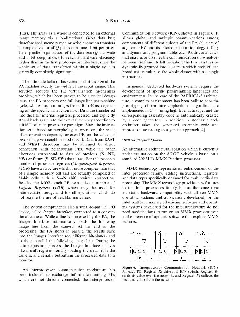
Figure 6. Interprocessor Communication Network (ICN):for each PE, Register R1 drives its ICN switch; Register R2
sends its value over the network; and Register R3 collects theresulting value from the network.
318 A. BROGGIETAL.
(PEs). The array as a whole is connected to an externalimage memory via a bi-directional Q-bit data bus;therefore each memory read or write operation transfersa complete vector of Q pixels at a time, 1 bit per pixel.This speci®c organization of the data-bus (Q bits wideand 1 bit deep) allows to reach a hardware e�ciencyhigher than in the ®rst prototype architecture, since thewhole set of data transferred within a single cycle isgenerally completely signi®cant.
The rationale behind this system is that the size of thePA matches exactly the width of the input image. Thissolution reduces the PE virtualization mechanismproblem, which has been proven to be a critical designissue. the PA processes one full image line per machinecycle, whose duration ranges from 10 to 40 ns, depend-ing on the speci®c instruction ¯ow. Data are transferredinto the PEs' internal registers, processed, and explicitlystored back again into the external memory according toa RISC-oriented processing paradigm. Since the instruc-tion set is based on morphological operators, the resultof an operation depends, for each PE, on the values ofpixels in a given neighborhood (565). Data from EASTand WEST directions may be obtained by directconnection with neighboring PEs, while all otherdirections correspond to data of previous (N, NE,NW) or future (S, SE, SW) data lines. For this reason anumber of processor registers (Morphological Registers,MOR) have a structure which is more complex than thatof a simple memory cell and are actually composed of51-bit cells with a S?N shift register connection.Besides the MOR, each PE owns also a number ofLogical Registers (LOR) which may be used forintermediate storage and for all operations which donot require the use of neighboring values.
The system comprehends also a serial-to-parallel I/Odevice, called Imager Interface, connected to a conven-tional camera. While a line is processed by the PA, theImager Interface automatically loads the followingimage line from the camera. At the end of theprocessing, the PA stores in parallel the results backinto the Imager Interface (on di�erent bit-planes) andloads in parallel the following image line. During thedata acquisition process, the Imager Interface behaveslike a shift-register, serially loading the data from thecamera, and serially outputting the processed data to amonitor.
An interprocessor communication mechanism hasbeen included to exchange information among PEswhich are not directly connected: the Interprocessor
Communication Network (ICN), shown in Figure 6. Itallows global and multiple communications amongcomponents of di�erent subsets of the PA (clusters ofadjacent PEs) and its interconnection topology is fullyand dynamically programmable: each PE drives a switchthat enables or disables the communication (in wired-or)between itself and its left neighbor; the PEs can thus bedynamically grouped into clusters in which each PE canbroadcast its value to the whole cluster within a singleinstruction.
In general, dedicated hardware systems require thedevelopment of speci®c programming languages andenvironments. In the case of the PAPRICA-3 architec-ture, a complex environment has been built to ease theprototyping of real-time applications: algorithms areimplemented in C�� using high-level data types and thecorresponding assembly code is automatically createdby a code generator; in addition, a stochastic codeoptimizer takes the generated assembly code andimproves it according to a genetic approach [4].
General purpose system
An alternative architectural solution which is currentlyunder evaluation on the ARGO vehicle is based on astandard 200MHz MMX Pentium processor.
MMX technology represents an enhancement of theIntel processor family, adding instructions, registers,and data types speci®cally designed for multimedia dataprocessing. The MMX technology provides new featuresto the Intel processors family but at the same timemaintains backward compatibility with all non-MMXoperating systems and applications developed for theIntel platform, namely all existing software and operat-ing systems developed for the Intel architecture do notneed modi®cations to run on an MMX processor evenin the presence of updated software that exploits MMXfeatures.

Figure 7. The MMX data types, their ordering, the mostsigni®cant byte (MSB), and the least signi®cant byte (LSB).
VISION-BASEDAUTOMATIC VEHICLEGUIDANCE 319
On the other hand, software performance can beboosted by exploiting a SIMD technique: multiple dataelements can be processed in parallel using a singleinstruction. The new general-purpose instructions sup-ported by MMX technology perform arithmetic andlogical operations on multiple data elements packed into64-bit quantities. These instructions accelerate theperformance of applications based on compute-intensivealgorithms that perform localized recurring operationson small native data. More speci®cally in the processingof gray-level images, data is represented in 8-bitquantities, hence an MMX instruction can operate on8 pixels simultaneously.
Basically the MMX extensions provide the program-mers with the following new features:
MMX registersThe MMX technology provides 8 general-purpose 64-bitnew registers. The main problem the Intel architects hadto face was the backward compatibility with the existingsoftware and speci®cally with the multi-tasking operat-ing systems. In fact in a multi-tasking environment acontext switch operation requires to save or restore theCPU status and register the contents. Neverthelessexisting operating systems do not know the presenceof MMX registers. In addition, di�erent operatingsystems take di�erent approaches for the state savingand restoring [20, 6]. To cope with these problemsMMX registers have been overlapped to the ¯oatingpoint registers. Hence, when ¯oating point registers aresaved or restored also MMX registers are saved orrestored, thus allowing existing operating systems to runwithout modi®cations.On the other hand this solution has two drawbacks:
(1) the programmer is expected not to mix MMXinstructions and ¯oating point code in any way, but isforced to use a speci®c instruction (EMMS) at the end ofevery MMX enhanced routine. The EMMS instructionempties the ¯oating point tag word, thus allowing thecorrect execution of ¯oating point operations;
(2) frequent transitions between the MMX and ¯oating-point instructions may cause signi®cant perfor-mance degradation.
MMX data typesThe MMX instructions can handle four di�erent 64-bitdata types (see Figure 7):
(1) 8 bytes packed into one 64-bit quantity;(2) 4 words packed into one 64-bit quantity;
(3) 2 double-words packed into one 64-bit quantity; or(4) 1 quadword (64-bit).
This allows to process multiple data using a singleinstruction or to directly manage 64-bit data.
MMX arithmeticsThe main innovation of the MMX technology consistsof two di�erent methods used to process the data:
(1) saturation arithmetic; and(2) wraparound mode.
Their di�erence depends on how the over¯ow orunder¯ow caused by mathematical operations ismanaged. In both cases MMX instructions do notgenerate exceptions nor set ¯ags, but in wraparoundmode, it results that over¯ow or under¯ow are truncatedand only the least signi®cant part of the result isreturned; conversely, the saturation approach consists insetting the result of an operation that over¯ows to themaximum value of the range, as well as the result of anoperation that under¯ows is set to the minimum value.For example, packed unsigned bytes for results thatover¯ow or under¯ow are saturated to 06FF or to0600, respectively.
The latter approach is very useful for gray-level imageprocessing, in fact, saturation brings the gray value topure black or pure white, without allowing for aninversion as in the former approach.
MMX instructionsMMX processors are featured by 57 new instructions,which may be grouped into the following functionalcategories: arithmetic instructions, comparison instruc-tions, conversion instructions, logical instructions, shift

320 A. BROGGIETAL.
instructions, data transfer instructions, and the EMMSinstruction. All MMX instructions, except the EMMSone, have two operands: source (the left one) anddestination (the right one). The source operand for allthe MMX instructions (except for the data transferinstructions), can reside either in memory or in anMMX register, while the destination operand mustreside in an MMX register.
Algorithms implementation
The low-level portion of the algorithms described inobstacle and lane detection have been implemented andtested on both the PAPRICA-3 and the Pentium MMXarchitectures. the PAPRICA-3 assembly code has beengenerated using the code generator starting from a C��source, while the assembly code for the MMX im-plementation has been written directly by hand: sinceupto now there is no standard C compiler that handlesMMX extensions, whereas, in case of a future avail-ability, probably an automatic parallelizing compilerwould not generate a fully optimized code unless somead hoc C statements are introduced to help theparallelization.
According to the analysis in [1] the two followingcategories of operations have been considered:
(1) Pointwise operations: the new status of each imagepixel is computed as a function of the previousvalues of the same pixel; they are used for simpleoperations, such as thresholding or imagedi�erence.
(2) Cellular Automata operations: the new status ofeach pixel is computed as a function of the values ofthe pixel's neighbors; they are used for operationssuch as morphological ®lters or adaptivethresholding.
For the sake of simplicity and for comparison purposes,the following two examples, one for each abovecategory, are considered: absolute di�erence betweentwo images (pointwise operation used for obstacledetection), and brightness comparison in a horizontalneighborhood (cellular automation operation used forlane detection).
Since these operations are performed on 8-bit gray-level images; the MMX processor handles 8 pixelssimultaneously, while PAPRICA-3 operates on a singlebit of every pixel of a full image line at the same time.
Absolute di�erence between two imagesA pixelwise comparison of two images is performed.Every pixel of the resulting image is obtained computingthe absolute di�erence between the corresponding pixelsof the two images. In the case of the MMX-basedprocessor, naming a and b the two images, the followingtwo unsigned di�erences ud1 � aÿ b and ud2 � bÿ aare computed. Thanks to the saturation arithmetic ud1 isnull where a5b as well as ud2 � 0 where a4b, thus theabsolute value ud � jaÿ bj can be computed asud � ud1 _ ud2. Conversely, the PAPRICA-3 implemen-tation is based on a single signed di�erence (sd � aÿ b)that gives a two's complement 9-bit result, whose ninthbit (s) is the sign. The ®nal result ud � jaÿ bj iscomputed as the eight less signi®cant bits of sd � 1 incase s is set, and as the eight less signi®cant bits of sdotherwise.
Brightness comparison in a horizontal neighborhoodThe value of every pixel is computed as a function of itsvalue and the values of its left and right neighbors at adistance of 2. In the MMX implementation, multipleaccesses to the memory are required; there are twodi�erent approaches to this problem:
(1) using a single access to the memory, the pixel valueas well as the values of its neighbors are loaded intoa single MMX register; in order to perform thecomparison several shift operations must be used toalign the pixels with its second neighbors.Unfortunately these shift operations reduce thenumber of pixel that can be processedsimultaneously for each memory access from 8 to4 (Figure 8(a)). Thus, two read accesses to thememory are required for the processing of 8 pixels;
(2) conversely, using three accesses to the memory, thepixel value and the values of its neighbors can beloaded in three di�erent MMX registers in such away that they have the correct alignment. In thiscase, 8 pixels can be processed simultaneously andthere is no need for shift operations (Figure 8(b)).
On the other hand, in the PAPRICA-3 architecture,the PEs can directly access data held in their neighbor-hood, thus it is possible to process one full line after asingle load operation. Moreover, in case the cellularautomation is based on a wider neighborhood, PAPRI-CA-3 has no additional overhead, while the MMXimplementation requires a su�ciently large number ofregisters and memory accesses.

Figure 8. Two di�erent approaches to a cellular automationoperation in the MMX technology involving 8-bit pixels A, B,and C: (a) a single access to the memory followed by shiftoperations; (b) three partially overlapped accesses to memory.
VISION-BASEDAUTOMATIC VEHICLEGUIDANCE 321
More generally, when considering pointwiseoperations on 8-bit deep images, the MMX-basedprocessor and PAPRICA-3 architecture have similarbehavior, the only di�erences being the instruction sets
and the number of pixels that can be processedsimultaneously. Nevertheless, since PAPRICA-3 is asingle bit processor, it can also e�ciently handle imageswith a generic depth, while the MMX instruction set isable to handle ®xed-depth images (8, 16, 32, or 64 bit/pixel) only.
Finally, the PEs of PAPRICA-3 are able to accessdirectly the data of the neighboring PEs, thus allowing ahighly e�cient implementation of cellular automataoperations. Conversely, in the MMX technology multi-ple accesses to the memory are required and this reducesthe overall performance, even if this e�ect is lessened bythe presence of multiple levels of cache memory.
Performance evaluation
For comparison purposes the algorithms described inobstacle and lane detection have been evaluated on thePAPRICA-3 architecture, featuring 256 processors, a100MHz clock and a 20 ns memory access time, and ontwo di�erent MMX Intel Pentium architectures, featur-ing a 66MHz bus speed and a 166MHz or 200MHzprocessor clock.
Table 1 shows the results for the low-level portion oflane and obstacle detection algorithms [3] which includeboth pointwise operations and cellular automata ®lters.The size of the processed images in 2566256 pixels. As a®rst consideration, it is important to note that theprocessor clock variation between the two MMX basedprocessors does not seem to equally a�ect the executiontime: infact, despite a frequency increase of 20% only11±15% speedups have been measured. The rationalebehind this result is that both systems use the same bus(66MHz) for memory access which, for this implemen-tation, represents the actual bottleneck.
These results show that PAPRICA-3 performs two tofour times better than MMX processors depending onthe algorithm. It should be considered, however, thatthese results have been obtained in a con®gurationwhere both architectures o�er the maximum e�ciency:namely when the number of PEs matches the imagewidth in case of PAPRICA-3, and when processing 8-bit-deep images for the MMX based processor. Whilethe ®rst condition is assumed to be valid, the processingof images with a reduced depth is generally envisaged,particularly for real-time constrained applications; inthis case PAPRICA-3 reaches higher e�ciency levelsthan MMX based processors.

Table 1. Performance evaluation on PAPRICA-3 and MMX based architectures; the values referring to the PAPRICA-3 systemhave been obtained thanks to a simulator
Low-levelobstacle detection (ms)
Low-levellane detection (ms)
PAPRICA-3 (100MHz, 256 PEs) 1.04 1.67Pentium MMX (166Mz) 3.2 7.0Pentium MMX (200MHz) 2.7 6.2
322 A. BROGGIETAL.
Discussion
In this work both the architectural and algorithmicaspects of the challenging problem of automaticvehicle guidance have been discussed. In particular,two di�erent solutions have been pointed out andanalysed: in general, the former, based on a special-purpose processing system, requires the complete designof the computer architecture as well as a programminglanguage and a debugging environment. Conversely,the latter takes advantage of standard developmenttools and environments but su�ers from a less speci®cinstruction set and a less oriented system architecture.Moreover, since the use of MMX extensions relieson a SIMD computational paradigm which cannot befully exploited by a standard C compiler, speci®capproaches are needed: in fact, in order to obtain ahighly e�cient code, either assembly code-speci®cparallel programming extensions to the C language arerequired.
Nevertheless, the advantages o�ered by the ®rstsolution, such as an ad hoc design of both theprocessing paradigm and the overall system architec-ture, are diminished by the necessity of managingthe complete project, starting from the hardwarelevel (design of the ASICs) upto the design of thearchitecture, to the programming language along withan optimizing compiler, and ®nally to the developmentof applications using the speci®c computational para-digm.
Anyway, in the comparison between these twosolutions not only the details about the architecturemust be taken into account, but the technologicalaspects need to be considered as well, the main issuesbeing:
(1) the fast technological improvements, which tend toreduce the life-time of the system;
(2) the costs of the system design and engineering,which are justi®ed for productions based on largevolumes only.
These additional considerations point out that assoon as a new technological process becomes available,the design must be reconsidered from scratch, since newcomputational paradigms could bene®t from the incre-ment in the computational power derived by a higherintegration, as happened for SIMD processors and forMMX extensions.
The development of dedicated architectures was oneof the main research directions in the mid 1980s, whenthe technology was pushed at its limits and general-purpose processors could not provide su�cient compu-tational power to support fast processing of large datastructures, like bit-mapped images. The ``general-pur-pose'' solution was de®nitely unsuitable for somespeci®c problems for which even expensive ad hocsolutions based on long-design, development, andtesting times were justi®ed.
Then, when SIMD machines became possible, a largenumber of simple processing elements were integratedon the same chip. There was a large explosion of customarchitectures, mostly based on processor arrays with abi-dimensional grid interconnection scheme since it wasthought to be the best solution for image processing.Starting from the original ideas of Unger [31], Fountain[13] classi®ed in chronological order the di�erentresearch projects and implementations according to athree generation taxonomy.
The early ILLIAC [5] and CLIP [12] machines belongto the ®rst generation, mainly devoted to low-levelimage processing tasks. The second generation com-prises systems such as the ICL DAP [26], the GoodyearMPP [2] and the CLIP4 system [14] which have evolvedto complete processing systems with dedicated operating

VISION-BASEDAUTOMATIC VEHICLEGUIDANCE 323
systems and languages and extended the applicationspectrum to high-speed scienti®c computation.
The triggering factors of the third generation were theavailability and widespread use of VLSI technologies ofthe 1980s and the natural mapping of a bi-dimensionalinterconnection scheme over the planar structure of asilicon chip. This led to an explosion of di�erentproposals and implementations [30, 25, 19, 29, 27, 10]and in some cases to the redesign of previousarchitectures. Most designs share original characteristicssuch as the bidimensional mesh interconnection schemeand bit-serial computation, while other ones, such as theConnection Machine [29], have increased the complexityof the interconnection network or widened, as in theCLIP7 [15] or MasPar [24] systems, the data path of theelementary PE. Other machines, such as the AIS [27]and the PAPRICA-3 [16, 9], have a 1-D interconnectionscheme emulating a 2-D mesh organization.
These architectures demonstrated to be extremelyimportant since they allowed to design and e�cientlytest solutions based on new approaches and newcomputational paradigms, such as Cellular Automata[23] or Mathematical Morphology [28, 17].
Moreover, the following availability of fastinternet working facilities gave impulse to the MIMDparadigm, for which processors operating at very highclock frequencies were needed. Thanks to the wide-spreading of the Internet, in the mid-1990s, multimediaapplications gained more importance, and image pro-cessing became a basic tool for the solution of problemswhich were becoming more and more common. There-fore, after a ®rst stage in which ad hoc hardware boardswere build to support fast image compression, andimage processing, general-purpose processors were builtconsidering that much of their computational power hadto be devoted to the processing of images. Although in aperiod of technological pressure, Intel introduced theMultimedia Extension (MMX) technology, which,thanks to an overlapping with hardware used in ¯oatingpoint operations and to a small increment in the chipsize, included speci®c instructions tailored to theprocessing of new data structures, such as pixels.
Under this framework, the advantages o�ered by adhoc solutions are more and more con®ned in a small andspeci®c application ®eld, where hard constraints imposethe design of a speci®c system architecture, for examplein the development of embedded systems such as in theautomotive ®eld.
Trends in the Automotive Field
Similar issues have been addressed by other researchinstitutes working in the automotive ®eld (a thoroughsurvey of state-of-the-art research can be found in [8]).The great majority of the projects involving the use ofmachine vision as a mean to sense the environmentstarted 5 to 10 years ago with the development of ad hoccomputer architectures that could provide su�cientcomputational power to support low-level image pro-cessing. Among them, the most important and signi®-cant examples are the cases of Carnegie MellonUniversity (Pittsburgh, PA) and UniversitaÈ t der Bun-deswehr (MuÈ nchen, Germany), where both researchgroups developed their own system architectures: inthe ®rst case a 16 k MasPar MP-2 was installed onthe experimental vehicle NAVLAB I [21, 22], and in thesecond case special-purpose boards were included inthe Transputer-based architecture of VITA.
On the other hand, both groups are currently headingtheir research toward the use of general-purposeprocessors (such as the Intel family) in a commercialarchitecture with o�-the-shelf components, such asframe-grabbers and I/O boards. These systems can bee�ciently used to test the algorithms and any newapproach without worrying about the technologicaladvances during the course of the project. Once thealgorithms have been de®ned, tested, and tuned accord-ing to the speci®c application and environment, theengineering phase may take place in order to producethe ®nal embedded system taking advantage of up-to-date technology.
As a ®nal consideration, current technology allows tohave su�ciently powerful processing engines to providean e�cient development infrastructure (consideringboth hardware devices and programming tools). Ob-viously, since the ®nal product generally needs speci®ccharacteristics such as low cost, low power consumptionand low physical size, the ®nal phase will consist of there-engineering of the whole system leading to a special-purpose ad hoc product.
Therefore, although some years ago the extremelyexpensive development of special-purpose hardware wasrequired because of the low performance of general-purpose systems, currently the special-purpose solutionis the basis for the ®nal marketing product in speci®chard-constrained applications.

324 A. BROGGIETAL.
Acknowledgement
This work has been partially supported by the ItalianNational Research Council (CNR) in the framework ofthe MADESS2 Project; up to date information can befound at http://millemiglia.ce.unipr.it
References
1. Ballard, D. H. & Brown, C. M. (1982) Computer Vision.Prentice Hall.
2. Batcher, K. (1980) Design of a Massively parallelprocessor. IEEE Transactions on Computers C-29:836±840.
3. M. Bertozzi & Broggi, A. (1988) GOLD: a Parallel Real-Time Stereo Vision System for Generic Obstacle and LaneDetection. IEEE Transactions on Image Processing, 7(1):62±81.
4. M. Bertozzi & Broggi, A. (1998) Tools for codeOptimization and System Evaluation of the ImageProcessing System PAPRICA-3. Journal of SystemsArchitecture, 45: 519±542.
5. Bouknight, W. L. et al. The ILLIAC IV system. IEEEProceedings, 60: 369±388, 1972.
6. Bray, B. B. (1996) Programming the 80286, 80386, 80486and Pentium-based Personal Computer. Englewood Cli�s,New Jersey, USA: Prentice Hall, Inc.
7. Broggi, A. (1998) Special-Issue on ``Machine Vision forIntelligent Vehicles and Autonomous Robots,'' A. Broggiguest-editor. International Journal on Engineering Applica-tions of Arti®cial Intelligence, 11(2).
8. Broggi, A., Bertozzi, M., Fascioli, A. & Conte, G. (1999).Automatic Vehicle Guidance: the Experience of the ARGOAutonomous Vehicle. World Scienti®c Co. Publisher,Singapore. ISBN 981-02-3720-0
9. Broggi, A., Conte, G., Gregoretti, F., SansoeÁ , C.,Passerone, R., & Reyneri, L. M. (1998) Design andImplementation of the PAPRICA Parallel Architecture.The Journal of VLSI Signal Processing, 19(1): 5±18.
10. Broggi, A., Conte, G., Gregoretti, F., SansoeÁ , C., &Reyneri, L. M. (1997) The Evolution of the PAPRICASystem. Integrated Computer-Aided Engineering Journal -Special Issue on Massively Parallel Computing, 4(2):114±136.
11. Broggi, A. & Gregoretti, F. (1996) Special-Issue on``Special-Purpose Architectures for Real-Time Imaging,''A. Broggi and F. Gregoretti guest-editors. Real-TimeImaging Journal, 2(6): 329±330.
12. Du�, M., Watson, D. M., Fountain, T. & Shaw, G. (1973)A Cellular Logic array for Image Processing. PatternRecognition, 15: 229±247.
13. Fountain, T. (1987) Processor Arrays: Architectures andapplications. Academic-Press, London.
14. Fountain, T. & Goetcherian, V. (1980) CLIP4 ParallelProcessing System. IEEE Proceedings, 127E: 219±224.
15. Fountain, T. & Matthews, K. (1988) The CLIP 7A ImageProcessor. IEEE Transactions on Pattern Analysis andMachine Intelligence, 10(3): 310±319.
16. Gregoretti, F., Passerone, R., SansoeÁ , C. & Broggi, A.(1996) The PAPRICA-3 Parallel Processor. In ProceedingsMIPRO'96 Symposium , Opatija, Croatia.
17. Haralick, R. M., Sternberg, S. R. & Zhuang, X. (1987)Image Analysis Using Mathematical Morphology. IEEETransaction on Pattern Analysis and Machine Intelligence,9(4): 532±550.
18. Helman, D. & Ja ja , J. (1995) E�cient Image ProcessingAlgorithms on the Scan Line Array Processor. IEEETransactions on Pattern Analysis and Machine Intelligence,17(1): 47±56.
19. Robinson, I. N. & Moore, W. R. (1982) A parallelprocessor array architecture and its implementation insilicon. In Proceedings of IEEE Custom Integrated CircuitsConference, 41±45, New York, Rochester.
20. Intel Corporation. MMX Technology Programmers Re-ference Manual. Intel Corporation, 1997. Available athttp://www.intel.com.
21. Jochem, T. M. & Baluja, S. A. (1993) Massively ParallelRoad Follower. In M. A. Bayoumi, L. S. Davis, and K. P.Valavanis, (eds.), Proceedings CAMP'93 - ComputerArchitectures for Machine Perception, pages 2±12, NewOrleans, IEEE Computer Society.
22. Jochem, T. M. & Baluja, S. (1993) Massively Parallel,Adaptive, Color Image Processing for Autonomous RoadFollowing. In: Kitano, H. (ed.), Massively ParallelArti®cial Intelligence. AIII Publishers in cooperation withMIT Press.
23. Margolus, N. & To�oli, T. (1990) Cellular AutomataMachines. In: Doolen, G. D. et al., (ed.), Lattice GasMethods for Partial Di�erential Equations. Redwood City,California, Addison Wesley, pp. 219±249.
24. MasPar Computer Corporation, Sunnyvale, California.MP-1 Family Data-Parallel Computers, 1990.
25. NCR Corporation, Dayton, Ohio. Geometric ArithmeticParallel Processor, 1984.
26. Reddaway, S. (1973) DAP±A Distributed Array Proces-sor. In 1st Annual Symposium on Computer Architectures,pages 61±65, Florida.
27. Schmitt, L. A. & Wilson, S. S. (1988) The AIS-5000Parallel Processor. IEEE Transactions on Pattern Analysisand Machine Intelligence, 10(3): 320±330.
28. Serra, J. (1982) Image Analysis and Mathematical Mor-phology. Academic Press, London.
29. Thinking Machines Corporation, Cambridge, Ma. (1991)Connection Machine CM-200 Series - Technical Summary.
30. Sudo, T., Nakashima, T., Aoki, M. & Kondo, T. (1982) AnLSI adaptive array processor. In Proceedings IEEE Inter-national Solid-State Circuits Conference, pages 122, 123,307.
31. Unger, S. (1958) As computer oriented toward spatialproblems. Proceedings IRE, 46: 1744±1750.