Embed Size (px)
Citation preview
1
Arc Plasma Torch Modeling
J. P. Trelles, C. Chazelas, A. Vardelle and J. V. R. Heberlein
Abstract
Arc plasma torches are the primary components of various industrial thermal plasma processes
involving plasma spraying, metal cutting and welding, thermal plasma CVD, metal melting and
remelting, waste treatment and gas production. They are relatively simple devices whose operation
implies intricate thermal, chemical, electrical, and fluid dynamics phenomena. Modeling may be used
as a means to better understand the physical processes involved in their operation. This paper
presents an overview of the main aspects involved in the modeling of DC arc plasma torches: the
mathematical models including thermodynamic and chemical non-equilibrium models, turbulent and
radiative transport, thermodynamic and transport property calculation, boundary conditions and arc
reattachment models. It focuses on the conventional plasma torches used for plasma spraying that
include a hot –cathode and a nozzle anode.
Keywords: plasma torch, plasma spraying, thermal plasma, local thermodynamic equilibrium,
chemical equilibrium, non-equilibrium, arc reattachment, plasma jet, electrode
Nomenclature
A magnetic vector potential kג spectral absorption coefficient
as,r stoichiometric coefficient in the forward
direction for the reaction r
kf,r forward reaction rate for reaction r
B magnetic field kb,r backward reaction rate for reaction r
bs,r stoichiometric coefficients in the backward
direction for the reaction r
Ms molecular weight of species s
Cµ constant of k-ε model me electron mass
Cε1 constant of k-ε model ne Electron number density
Cε2 constant of k-ε model ns number of species
Ds effective diffusivity of species s nr number of reactions

2
Dsj binary diffusion coefficient species s and j p pressure
E real electric field ehQ electron – heavy-particle energy
exchange
Eb critical electric field rQ volumetric net radiation losses
Ep effective electric field qa heat transferred to the anode surface
e elementary electric charge qr radiative heat flux
Gk generation of turbulent kinetic energy qwall heat transferred to the wall
h plasma specific enthalpy q' total heat flux
he electron specific enthalpy r radius
hh heavy particles specific enthalpy Rs gas constant of species s
hw heat transfer coefficient T temperature
I Arc current intensity Tw wall temperature
Iλ spectral intensity Tc critical temperature
Ibλ spectral black body intensity Te electron temperature
Jcath current density over the cathode surface Th heavy particle temperature
Jq arc current density t time
Js mass diffusion flux of species s u mass average velocity
k turbulent kinetic energy us velocity of species s
k total thermal conductivity Wa work function of the anode material
kB Boltzmann constant x spatial coordinate
ke electron translational thermal conductivity
kh heavy particles thermal conductivity
kr reactive thermal conductivity
Greek Letters Subscripts
δ Kronecker delta a anode
δes inelastic collision factor e electron
ε turbulent dissipation rate h heavy particle
εr effective net emission coefficient j specie
θ departure from thermal equilibrium k turbulent kinetic energy
φp effective electric potential r reactants or reactions

3
λ wavelength s Species
µ molecular dynamic viscosity t turbulent
µ0 permeability of free space w wall
µt turbulent dynamic viscosity ε turbulent dissipation rate
ρ mass density
ρs mass density of species s csρ volumetric production rate of species s
σ Electrical conductivity
σk constant of k-ε model
τ stress tensor
νes collision frequency between electrons and
species s
ω reaction molar rate
ψ conserved property
rϖ progress rate of reaction r
Δ Finite change in quantity
Acronyms
CFD Computational Fluid Dynamics
DC Direct Current
DES Detached Eddy Simulation
SCEBD Self-Consistent Effective Binary Diffusion
DNS Direct Numerical Simulation
DOM Discrete Ordinates Methods
RANS Reynolds-Averaged Navier-Stokes
EEDF Electron Energy Distribution Function
LES Large Eddy Simulations
LTE Local Thermal Equilibrium
NEC Net Emission Coefficient
NLTE Non Local Thermal Equilibrium
RTE Radiative Transfer Equation
HVOF High Velocity Oxygen Fuel

4
1. Introduction
Thermal plasma processes have proven their technological advantage in a wide variety of fields
for over 40 years. The features that make thermal plasmas attractive are a high energy density ( ~ 106-
107 J/m3) that comes with high heat flux density (~ 107-109W/m2), high quenching rate (~ 106-108
K/s), and high processing rates.
Direct current (DC) arc plasma torches are, generally, the primary component of these processes
that include plasma spraying, ultra fine particle synthesis, metal welding and cutting but also,
extractive metallurgy, waste treatment and biogas production. These torches operate as thermal,
chemical, and electrical devices in processes that achieve material modifications which often cannot
be achieved, or are not economically feasible, with other devices. A distinctive example of an
application that relies on DC arc plasma torches is plasma spraying that has become a well-
established and widely used technology to manufacture coatings resistant to wear, corrosion and
temperature and generate near-net shapes of metallic and ceramic parts. For instance, plasma-sprayed
coatings make possible turbine blades to withstand temperatures up to 1200 °C and provide
unparalleled wear-resistance to prosthetic implants. The continuous development of thermal plasma-
based technologies stresses the need for a better understanding of the operation of arc plasma torches.
Fig. 1 Scheme of the plasma flow inside a non-transferred DC arc plasma torch and high speed image
of the plasma jet; the diameter of the anode at the torch exit is typically ~ 6 – 10 mm
The apparent simplicity of a DC arc plasma torch is in marked contrast with the complexity of the
electrical, chemical, and thermal phenomena involved in its operation. Most DC arc torches have
three main components: The cathode, the plasma-forming gas injection stage, and the anode. The
anode usually also acts as arc constrictor in so-called non-transferred arc torches (Fig. 1) or forms part
of the processing material outside the torch in transferred arc torches (Fig. 2) (Ref 1). Non-transferred
5
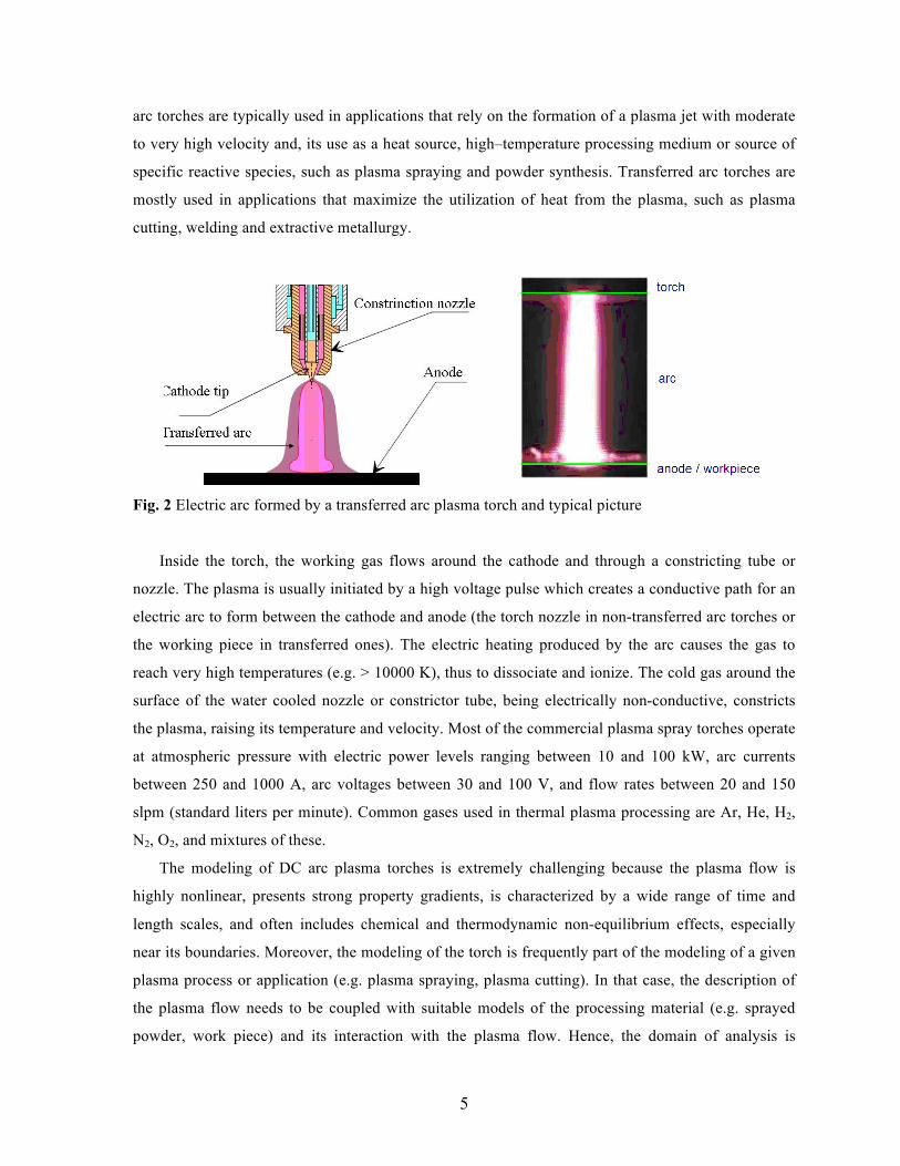
arc torches are typically used in applications that rely on the formation of a plasma jet with moderate
to very high velocity and, its use as a heat source, high–temperature processing medium or source of
specific reactive species, such as plasma spraying and powder synthesis. Transferred arc torches are
mostly used in applications that maximize the utilization of heat from the plasma, such as plasma
cutting, welding and extractive metallurgy.
Fig. 2 Electric arc formed by a transferred arc plasma torch and typical picture
Inside the torch, the working gas flows around the cathode and through a constricting tube or
nozzle. The plasma is usually initiated by a high voltage pulse which creates a conductive path for an
electric arc to form between the cathode and anode (the torch nozzle in non-transferred arc torches or
the working piece in transferred ones). The electric heating produced by the arc causes the gas to
reach very high temperatures (e.g. > 10000 K), thus to dissociate and ionize. The cold gas around the
surface of the water cooled nozzle or constrictor tube, being electrically non-conductive, constricts
the plasma, raising its temperature and velocity. Most of the commercial plasma spray torches operate
at atmospheric pressure with electric power levels ranging between 10 and 100 kW, arc currents
between 250 and 1000 A, arc voltages between 30 and 100 V, and flow rates between 20 and 150
slpm (standard liters per minute). Common gases used in thermal plasma processing are Ar, He, H2,
N2, O2, and mixtures of these.
The modeling of DC arc plasma torches is extremely challenging because the plasma flow is
highly nonlinear, presents strong property gradients, is characterized by a wide range of time and
length scales, and often includes chemical and thermodynamic non-equilibrium effects, especially
near its boundaries. Moreover, the modeling of the torch is frequently part of the modeling of a given
plasma process or application (e.g. plasma spraying, plasma cutting). In that case, the description of
the plasma flow needs to be coupled with suitable models of the processing material (e.g. sprayed
powder, work piece) and its interaction with the plasma flow. Hence, the domain of analysis is

6
typically extended beyond the plasma and across the torch components (e.g. to model the electrical
characteristics across the electrodes, or the dissipation of heat to the cooling water) and/or the
working material (e.g. to describe heat transferred and phase changes in the processing powder or
work piece).
This paper presents an overview of the main aspects involved in DC arc plasma torch modeling,
as well as some examples that typify the current state of the art. Particular emphasis is given to
conventional non-transferred arc plasma torches with thermionic (hot) cathodes as those employed in
plasma spraying. Section 2 describes the physical/mathematical models used to describe the plasma
flow, including turbulent and radiative transport models. Section 3 presents calculation procedures for
the gas thermodynamic and transport properties that are fundamental for a realistic and accurate
description of thermal plasmas. Boundary conditions, which seek to represent the physical
phenomena dominating the interactions between the computational domain of the plasma flow and its
surroundings, are described in Section 4. Section 5 describes models of the arc reattachment process,
a complex phenomenon which severely alters the arc dynamics and is inherently present in the flow
inside non-transferred arc torches. Finally, in Section 6, conclusions are drawn and some of the
developments required for furthering the current understanding of plasma torch operation and
achieving truly predictive DC arc plasma torch models, are presented.
2. Plasma Flow Models
2.1 Fluid Models
The plasma formed in DC arc torches is an example of a thermal plasma. Among other things,
thermal plasmas are characterized by high electron density (ranging between 1021 and 1024 m-3) and
high collision frequencies among its constituents (i.e. molecules, atoms, ions, and electrons) (Ref 1).
High collision frequencies lead to a state close to local thermodynamic equilibrium (LTE) in which
the kinetic energy of the constitutive species can be characterized by a single temperature. The LTE
approximation is often violated near the plasma boundaries, either as the plasma interacts with solid
walls, the working material, or with the cold working gas or atmosphere.
Thermal plasmas, due to their relatively high densities and pressures, and hence small mean free
paths of the constitutive species, are most appropriately described by fluid models. Fluid models
describe the evolution of the moments of the Boltzmann equation for each species in the plasma, and
provide direct measures of macroscopic flow properties, such as temperature and pressure.

7
The fluid part of thermal plasma models can be expressed as a set of general transport equations
expressed in conservative form as a balance among accumulation, net flux, and production; namely:
∂ψ∂t
accumulation
+∇⋅ fψnet flux
− sψ production
= 0 , (Eq 1)
where ψ is a conserved property, t represents time, fψ is the total (i.e. advective plus diffusive) flux of
ψ, and sψ is the net production/depletion rate of ψ.
Table 1 Conservation equations of the thermodynamic and chemical equilibrium thermal
plasma model
Conservation Accumulation Net flux Net production
Total mass t∂
∂ρ )( ρu⋅∇ 0
Mass-ave.
momentum t∂∂ uρ ∇⋅ (u⊗ ρu+ pδ+ τ) BJ ×q
Internal
energy th
∂∂ρ )'( qu +⋅∇ hρ Dp
Dt− τ :∇u+ Jq ⋅ (E+u×B)− Qr
Table 2 Conservation equations of the thermodynamic and chemical non-equilibrium thermal
plasma model
Conservation Accumulation Net flux Net production
Total mass t∂
∂ρ )( ρu⋅∇ 0
Species mass ts
∂
∂ρ )( ss Ju +⋅∇ ρ csρ
Mass-ave.
momentum t∂∂ uρ ∇⋅ (u⊗ ρu+ pδ+ τ) BJ ×q
Int. energy
heavy species thh∂
∂ρ )'( hhh qu +⋅∇ ρ DphDt
− τ :∇u+ Qeh
Int. energy
electrons the∂
∂ρ )'( eeh qu +⋅∇ ρ ehrqe QQ
DtDp −−×+⋅+ )( BuEJ

8
The most frequently used thermal plasma models rely on the LTE approximation, and model the
plasma flow as the flow of a property-varying electromagnetic reactive fluid in chemical equilibrium
in which the internal energy of the fluid is characterized by a single temperature T. The set of
conservation equations describing such a flow is shown in Table 1. A more detailed description of a
thermal plasma flow is given by allowing thermodynamic non-equilibrium (non-LTE or NLTE)
between the electrons and the heavy species; that is, the internal energy of the fluid is now
characterized by two temperatures: The electron temperature Te and the heavy species temperature Th.
Due to this fact, thermodynamic non-equilibrium thermal plasma models are also known as two-
temperature models. The set of equations describing a NLTE thermal plasma in chemical non-
equilibrium is listed in Table 2.
In Tables 1 and 2, ρ represents the total mass density, ρs the mass density of species s, u the
mass-averaged velocity, Js the mass diffusion flux and csρ the volumetric production rate of species
s; p represents the pressure, δ the Kronecker delta, τ the stress tensor, Jq the current density, B the
magnetic field, JqxB the Lorentz force; h, hh, and he the equilibrium, heavy-species and electron
enthalpy, respectively (no subscript indicates an equilibrium or total property, while the subscripts h
and e stand for heavy-particle and electron properties, respectively); q’ the total heat flux; Dp/Dt is
the pressure work with D/Dt as the substantive derivative; the term Jq⋅(E + uxB) represents the Joule
heating, rQ the volumetric net radiation losses, and ehQ the electron – heavy-particle energy
exchange term, which couples the two energy equations in the NLTE model. In Table 2, only ns–1,
where ns is the number of species, species mass conservation equations are required because the total
mass conservation equation is included in the system.
Several assumptions and approximations are implied in the equations in Table 1 and Table 2.
Particularly, closure of the moments of Boltzmann equation is taken into account in the specification
of diffusive fluxes and/or transport coefficients. Furthermore, there are different forms to express the
conservation equations in Tables 1 and 2, e.g. one could use conservation of total energy instead of
internal energy. The most important requirement when formulating equilibrium or non-equilibrium
plasma fluid models is self-consistency, which implies consistency with the moments of Boltzmann
equation. In this regard, up to the specification of diffusive fluxes and source terms csρ , ehQ , and rQ ,
the above models are self-consistent. Moreover, the LTE and NLTE models above are consistent with
each other in the sense that the NLTE model gets reduced to the LTE model if thermal and chemical
equilibrium are assumed (i.e. if one enforces Th = Te in the equations in Table 2 and if the plasma
composition is determined only as function of the thermodynamic state of the fluid). Furthermore, the
9
addition of the electron and heavy-species energy equations in Table 2 produces the total internal
energy conservation equation in Table 1.
2.2 Diffusion Fluxes and Source Terms
The systems of equations in Tables 1 and 2 are closed with the specification of diffusive fluxes Js,
τ and q’, and the source terms csρ , ehQ , and rQ .
The mass diffusion flux of species s is given by:
)( uuJ −= sss ρ , (Eq 2)
where us is the species s velocity. The evolution of us is described by a momentum conservation
equation derived from the Boltzmann equation for species s. For a more rigorous treatment of
chemical non-equilibrium than the one presented in Table 2, one momentum conservation equation
should be solved for each species (Ref 2). This procedure is exceedingly expensive, especially for the
modeling of industrial thermal plasma flows, as it would add (3ns – 1) equations. Thus, alternative
approaches are sought. These approaches seek to define mass diffusion fluxes as function of the other
macroscopic characteristics of the flow, such as temperature, pressure and concentration gradients.
The derivation of consistent mass diffusion fluxes for thermal plasmas is quite involved,
especially for two-temperature plasmas, due to the transport of charged species coupled to the
electromagnetic driving forces (Ref 3). One well-known approach for mass diffusion modeling in
thermal plasmas is the Self-Consistent Effective Binary Diffusion (SCEBD) approximation of
Ramshaw and Chang (Ref 4, 5). The SCEBD approximation models the mass diffusion fluxes
according to:
∑≠
+−=sj
jjj
sjss
ss
ss TR
DTRD '' GGJ
ρρ , (Eq 3)
where Ds is the effective diffusivity of species s, Dsj the binary diffusion coefficient between species s
and j, Rs and Ts are the gas constant and temperature of species s, respectively; and G’s is the total
driving force acting over species s, which is a function of the gradients of temperature, pressure,
concentrations, and of external forces (electromagnetic and gravitational). Ramshaw and Chang’s

10
model is still relatively expensive to apply in simulations of industrial thermal plasma processes. A
more practical approach is the Combined Diffusion method developed by Murphy (Ref 6) and
extended by Rat et al (Ref 7). This approach is based on the definition of combined diffusion
coefficients together with the grouping of species according to their parent gases. This model allows
the description of a thermal plasma in chemical and thermodynamic non-equilibrium by the transport
of groups of species related by their parent gases. As an example, an Ar-He plasma in chemical non-
equilibrium can be modeled by conservation equations of the group of species related to Ar (that is,
Ar, Ar+, Ar++) and the group related to He (He, He+). This approach is valid if the parent gases (e.g.
Ar and He above) do not react with each other.
The diffusive transport of momentum is modeled by the stress tensor τ , which is defined as for a
Newtonian fluid and is given by:
))(( 32 δuuuτ ⋅∇−∇+∇−= tµ , (Eq 4)
where µ is the dynamic viscosity, the superscript t indicates the transpose of matrix u, and the 2/3
factor in the fluid dilatation ∇⋅u comes from the Stoke’s hypothesis for the dilatational viscosity.
The total heat fluxes in the LTE and NLTE models describe the heat transported by conduction
and the enthalpy transport by mass diffusion. They are defined by:
∑+∇−=s
sshT Jq κ' , (Eq 5)
∑≠
+∇−=es
sshhh hT Jq κ' , (Eq 6)
eeeee hT Jq +∇−= κ' , (Eq 7)
where the summation in Eq 5 runs over all the species in the plasma; and κ, κh and κe are the total,
heavy species, and electron translational thermal conductivities, respectively.
A very useful and widely spread practice used in chemical-equilibrium thermal plasma models is
the use of a reactive thermal conductivity. Given that chemical equilibrium is assumed, the plasma
composition is only a function of the thermodynamic state of the plasma (e.g. the plasma composition
can be expressed as function of the equilibrium temperature T and total pressure p). Using this
approximation, the mass diffusion fluxes of heavy species (Js) can be expressed as functions of ∇T
and ∇p. Neglecting the contribution due to the pressure gradient, the total heat transferred by

11
conduction plus the heat transported by heavy species can be expressed as a reactive thermal
conductivity κr times ∇T; namely:
ThT res
ss ∇−=+∇− ∑≠
κκ J . (Eq 8)
The reactive thermal conductivity can be treated as any other transport property. It is primary a strong
function of the temperature T and only weakly a function of pressure. The energy transported by
electron mass diffusion in Eq 7 can be approximated by:
qe
e em JJ −≈ , (Eq 9)
where e is the elementary electric charge and me is the electron mass. Equation 9 neglects the charge
transported by the heavy species, which is a valid approximation for most thermal plasmas. The mass
diffusion flux of electrons is not included in the definition of the reactive thermal conductivity
because, as clearly implied in Eq 9, this flux is mostly driven by the electrical characteristics of the
system. By introducing Eq 8 and Eq 9 in Eq 5, we obtain the final expression for the total heat flux
which is often found in the literature, namely:
qe
r emT Jq −∇−= κ' . (Eq 10)
Equation 10 is particularly useful because it has a simple form and explicitly expresses the main
factors driving the transport of heat through the plasma.
The species production term csρ is similar to that found in standard reactive fluid dynamics
literature (e.g. Ref 8) and is given by:
r
nr
rrsrss
cs abM ϖρ ∑
=
−=1
,, )( , (Eq 11)
∏ ∏+−=ns
i
ns
i
b
i
irb
a
i
irfr
riri
Mk
Mk ,, )()( ,,
ρρϖ , (Eq 12)

12
where Ms is the molecular weight of species s, nr is the number of reactions, rϖ is the progress rate
of reaction r, as,r and bs,r are the reaction (e.g. stoichiometric) coefficients in the forward and
backward directions for the reaction r, and kf,r and kb,r are the forward and backward reaction rates for
reaction r.
The description of source term due to radiation transport is rather complex and will be explained
in Section 2.4. The final term to close the NLTE model is the electron - heavy-species energy
exchange term ehQ which is often modeled as (e.g. Ref 9):
)()(
223
2 heeseses es
esBeh TT
mmmmkQ −
+=∑
≠
δν , (Eq 13)
where kB is the Boltzmann constant, νes is the collision frequency between electrons and species s, and
δes is the inelastic collision factor, which is equal to 1 for atomic species. The term ehQ models the
average exchange of kinetic energy per unit volume between electrons and heavy species.
2.3 Electromagnetic Equations
The fluid models described in Section 2.1 are complemented with the equations describing the
evolution of the electromagnetic fields. These equations are the Maxwell’s equations, which, for
typical thermal plasmas, are simplified by neglecting relativistic effects, magnetization, as well as
charge accumulation. They are listed in Table 3.
Table 3 Maxwell’s equations for thermal plasmas
Name Equation
Ampere’s law: qJB 0µ=×∇
Faraday’s law: tp ∂
∂−=×∇BE
(Generalized) Ohm’s law: )( BuEJ ×+= pq σ
Gauss’ law (charge conservation): 0=⋅∇ qJ
Solenoidal Constraint: 0=⋅∇ B
13
In Table 3, µ0 represents the permeability of free space, σ electrical conductivity, and Ep the
effective electric field. The latter is used in Table 3, instead of the real electric field E, in order to
account for the so-called generalized Ohm laws. These laws take into account the dynamic
modification of the electromagnetic fields due to charge transport (i.e. charge transport is implied by
the mass diffusion fluxes Js of charged species) and, therefore, need to be consistent with the mass
diffusion model used in the fluid formulation (e.g. Eq 3). For LTE chemical-equilibrium models, it is
often assumed that E = Ep. For NLTE models, the main modification of the electric field is due to the
electron pressure gradient as shown in the following expression:
e
ep en
p∇+≈ EE , (Eq 14)
where ne is the electron number density. In more complete generalized Ohm laws, the effective
electric field is given by nonlinear expressions (e.g. Ep is a function of JqxB). The reader may realize
that the Joule heating term in Table 2 involves the real electric field E and not the effective one Ep; an
interesting discussion of the derivation of this term is found in (Ref 10).
The Maxwell’s equations listed in Table 3 can be expressed in different forms. Particularly useful
for thermal plasma flow solvers are the expressions based on electromagnetic potentials
tpp ∂∂
−−∇=AE φ and (Eq 15)
BA =×∇ , (Eq 16)
where φp is the effective electric potential (usually assumed equal to the electric potential φ in LTE
models) and A the magnetic vector potential. The use of the magnetic potential has the added
advantage that the solenoidal constraint is satisfied a priori. Using these potentials, Maxwell’s
equations can be expressed by:
0AAuA=∇−×∇×−∇+
∂∂ 2
0
1)(σµ
φ pt and (Eq 17)
0)( =×∇×−∂∂
+∇⋅∇ AuAtpφσ . (Eq 18)

14
Equation 17 is commonly known as a form of magnetic induction equation, whereas Eq 18 is just an
expression of charge conservation. Equation 17 can alternatively be expressed as:
qJA 02 µ−=∇ . (Eq 19)
Equation 19 is the most often used form of induction equation used in the thermal plasma
modeling literature, particularly as it is expressed as a relatively simple diffusion equation and
therefore amenable for its solution in fluid flow solvers.
2.4 Turbulence Models
In DC arc plasma torches the working gas is typically at ambient temperature when it enters the
torch. The temperature of the gas, as it interacts with the arc, increases by a rate in the order of 104
K/mm. This rapid heating causes the sudden expansion of the gas and consequently its rapid
acceleration. The velocity of the gas across the torch often varies by 2 orders of magnitude (e.g. from
O(10) to O(1000) m/s). The large gas acceleration and shear velocity and temperature gradients inside
the torch, together with the electromagnetic forcing (Ref 11, 12), cause the flow to become unstable
and turbulent. Turbulence is further enhanced when the plasma flow leaves the torch and interacts
with the cold and, thus, denser environment.
The accurate modeling of turbulent flows, due to their large range of length and time scales,
represents a great challenge. The most faithful numerical description of turbulent flows is given by
the approach known as Direct Numerical Simulation (DNS), which seeks to resolve all the scales of
the flow without any approximation (i.e. by definition, no physical, e.g. eddy viscosity, see below, or
numerical, e.g. upwinding, dissipation mechanisms are employed). DNS of large Reynolds number
(Re) flows and for industrial geometries are almost unfeasible with current computing power, as the
range of length scales to be solved (i.e. the size of the grid needed) scales as Re3. DNS of non-
equilibrium plasmas can be found in the literature (e.g. Ref 13) but, to the best knowledge of the
authors, no DNS of a thermal plasma has been performed to date.
The large cost of DNS has motivated a variety of alternative approaches to simulate turbulent
flows. The main approaches are grouped in what are known as Large Eddy Simulations (LES), which
seek to model only the small scales of the flow, and Reynolds-Averaged Navier-Stokes (RANS)
models, which seek the solution of approximations of the time-averaged Navier-Stokes Equations.
LES is typically far more accurate than RANS, but often an order of magnitude or more more
15
expensive. Recently, the technique known as Detached Eddy Simulation (DES) has been gaining
more acceptance, especially in the modeling of external flows, as it mixes the LES and RANS
approaches: LES is used where it is most needed (e.g. in highly unsteady zones) and RANS in the rest
of the domain or where the use of LES would be prohibitive (e.g. near walls, where vorticity is mostly
created).
Most LES and RANS models rely on the Boussinesq hypothesis, which consists of modeling the
turbulent stresses in a similar manner as the viscous stress and, hence, reduces the formulation of the
turbulence model to the specification of an appropriate turbulent viscosity µt (the total stress τ is still
given by Eq 4 but µ is replaced with µ + µt). More sophisticated models exist (Ref 14), which seek to
model the whole turbulent stress with very few or none empirical approximations, such as the
residual-driven model of Bazilevs et al (Ref 15). But these models, although they are potentially the
best approaches for the modeling of complex turbulent flows, are not widely used yet.
Diverse RANS and few LES models are often offered in commercial Computational Fluid
Dynamics (CFD) software, which has driven the increasing use of these models. Turbulent viscosity
models for LES are usually far simpler than models for RANS. But, sound LES simulations require
highly accurate spatial and temporal discretizations. These requirements are usually hard to satisfy
using commercial software because robustness, probably the most important feature in commercial
software, is very often in opposition to accuracy (e.g. it is harder to obtain convergence using more
accurate, high order, discretizations).
The use of turbulence models in thermal plasma flows is significantly more involved than for
most other industrial applications due to their inherent characteristics (i.e. reactivity, large property
variations and electromagnetic effects). The use of standard turbulent models for thermal plasma
simulation often implicitly neglects several of these characteristics.
Although some LES of DC arc plasma torches have been performed (Ref 16, 17), by far RANS
simulations dominate the thermal plasma literature. RANS models range from zero, one, and two
equation models to Reynolds-stress models, which model each component of the turbulent stress
tensor. By far the most widely used turbulence model in thermal plasma modeling is the k-ε model
developed by Launder and Spalding (Ref 18), where k stands for the turbulent kinetic energy and ε its
rate of dissipation (Table 4). In the derivation of the standard k-ε model, the flow is assumed to be
fully turbulent, and the effects of molecular viscosity are negligible. Furthermore, the standard k-ε is a
semi-empirical model, and the derivation of the model equations relies on phenomenological
considerations and empiricism.
Table 4 Equations of the standard k-ε turbulent model

16
Cons. Accumulation Net flux Net production
Turbulent
kinetic
energy tk
∂∂ρ ))(( kk
k
t ∇+−⋅∇σµ
µρu ρε−kG
Rate of
dissipation t∂∂ρε ))(( ε
σµ
µρεε
∇+−⋅∇ tu k
ck
Gc k
2
21ε
ρε
εε −
In Table 4, σk and σε are the Prandtl numbers for k and ε respectively, Gk represents the
generation of turbulent kinetic energy due to the mean velocity gradients, and cε1 and cε2 are model
constants. The turbulent viscosity for the k-ε model is defined by:
ερµ µ
2kct = (Eq 20)
More advanced k-ε models have been developed, which are more rigorously derived, more
accurate. They are valid for a wider variety of flows, and are also often available in several
commercial CFD software, like the RNG and the realizable k-ε models available in Fluent (Ref 19).
For example, the standard k-ε is only valid for fully turbulent flows, while the RNG k-ε is valid for
fully turbulent as well as for low- Reynolds number and near-wall flows.
To summarize, the use of turbulence models for the modeling of the flow in DC arc torches has to
be approached with care and weighting the assumptions and approximations involved. Particularly,
for the flow in non-transferred torches, which is highly unsteady, a LES approach is more
appropriate; whereas for the modeling of transferred torches, especially when the flow is steady, the
use of RNG k-ε or similar models may provide an adequate description of the flow. Nevertheless,
validation with experimental measurements is required, and when possible should be pursued.
2.5 Radiative Transport
Radiative transfer in thermal plasmas involves line and continuum radiation, including
bremsstrahlung and recombination radiation (Ref 1).
The total radiative flux source term of the energy equations shown in Tables 1 and 2 is given by:

17
rrQ q⋅∇= , (Eq 21)
where qr represents the radiative heat flux. The net radiation flux is a function of the spectral intensity
Iλ(x, s), which measures the radiation intensity in the point x along the direction s for a given
wavelength λ, according to:
∫ ∫∫∞∞
Ω−=⋅∇0
4
00
4π
λλλλ λκλκπ ddIdIbrq , (Eq 22)
with Ibλ as the spectral black body intensity, κλ the spectral absorption coefficient (which is a function
of the gas composition, pressure, temperature(s) and wavelength), and Ω the solid angle. The second
term on the right hand of Eq 22 implies integration over all directions and wavelengths. From Eq 22,
the radiative source term represents the difference between the emission and absorption occurring at a
given location x. The spectral intensity Iλ is found by solving the Radiative Transfer Equation (RTE),
which after neglecting time-dependency, scattering, and refraction effects, can be expressed as:
)(),( λλλλ κ III b −=∇⋅ sxs . (Eq 23)
Equation 23 models the energy transported by photons through the flow. Radiative media can
often be characterized by their optical thickness, which is a measure of the interaction that the
photons experience as they travel through a domain. It can be estimated by κλL, where L is a
characteristic length of the domain (e.g. torch diameter). In this regard, the plasma flow in DC arc
torches is usually considered as optically thin (κλL << 1) because it is often assumed that the photons
leave the plasma with very little interaction with the flow.
The direct solution of the RTE is exceeding expensive due to the dual s to x dependence, and
consequently diverse types of approximations are often employed. The detailed description of the
radiative transport in thermal plasmas represents an enormous challenge not only because of the
complex absorption spectra of the species present, but, also due to the weak interaction of the photons
with the surrounding media. This last characteristic jeopardizes the use of models that rely on strong
coupling (optically thick media), like diffusion-like models such as the P1 approximation, and makes
mandatory the use of more computationally expensive techniques like Direct Simulation Monte Carlo
or directional transport methods, like ray-tracing techniques and Discrete Ordinates Methods
(DOMs). The DOM consists of solving the RTE along few ordinate directions transforming the RTE

18
in a (typically large) set of transport equations. The P1 approximation consists of the formulation of a
transport equation (of reaction-diffusion form) for the first order term of the expansion of the
radiative intensity in spherical harmonics. The P1 method is a good approximation of the radiation
transport in optically thick media, and hence is not suitable for most DC arc plasma torch modeling.
Probably one of the best radiation transfer simulations applied to a thermal plasma flow is the
work of Menart et al (Ref 20) who used a DOM for a large set of wavelengths. Because their work
was focused on analyzing the radiative transfer, Menart et al did not solve the radiative transport
coupled to a plasma flow model. Instead, they used a pre-calculated temperature field in order to
determine κλ(T, λ) to solve the RTE. Their approach is justified by the enormous computational cost
required to solve the plasma flow together with radiative transport. More recently, Iordanidis and co-
workers (Ref 21, 22) compared the DOM and P1 methods and performed simulations of the plasma
flow in circuit breakers using the DOM due to its greater accuracy. An alternative approach is the use
of view factors to determine the exchange of radiative energy among the domain boundaries. Such
approach has been successfully used by Lago et al (Ref 23) for the simulation of a free-burning arc.
The form in which radiation directly interacts with the plasma flow (namely Eq 21) suggests that
detailed description of radiation transfer may not be needed and that direct approximations of rQ
could be used. This term can be approximated following a classical approach as done by Tanaka in
(Ref 24) for the modeling of an inductively coupled torch. But, by far, the most common
approximation used in thermal plasma modeling is the use of the effective net emission
approximation (Ref 25, 26, 27). Under this approximation, the net radiative flux is approximated
according to:
rrQ πε4= (Eq 24)
where εr is the effective net emission coefficient, which for a given plasma forming gas can be
expressed as function of temperature(s) and an effective absorption radius Rr. The latter represents the
radius of a sphere in which the emitted radiation can be re-absorbed; outside of this sphere, the
emitted radiation leaves without further interaction with the plasma (hence, the optically-thin
approximation implies Rr = 0). The net emission approach is particularly appealing for thermal
plasma flow simulation because the effective emission coefficient can be treated as any other
thermodynamic or transport property of the plasma.

19
At present, net emission coefficient (NEC) are available for the following pure gases (Ar, O2,
H2O, Air) and mixtures (Ar–H2, Ar-Fe, Ar-Fe-H2, Air-metallic vapors) (e.g. see Ref 28, 29, 30, 31,
32).
3 Gas Properties
In plasma simulations, mass, momentum and energy equations, together with electromagnetic
field equations (see Section 2.1), have to be solved with a coupled approach and the accuracy of
results depends strongly on the use of suitable thermodynamic and transport properties (see Section
2.2).
3.1 LTE thermodynamic and transport properties
The determination of thermodynamic and transport properties requires first the calculation of
plasma composition that can be obtained either from a chemical non-equilibrium model (e.g. see
Table 2) or chemical equilibrium models based on mass action laws or minimization of Gibbs free
energies. Thermodynamic properties are directly calculated from the particle number densities of the
various species forming the plasma and previous knowledge of the internal partition functions.
(a)
(b)
Fig. 3 (a) Temperature dependence of the composition (species number densities) in an argon-
hydrogen (75/25% vol) at atmospheric pressure and (b) specific enthalpy (MJ/kg) of various Ar-H2
gas mixture at atmospheric pressure versus temperature (Ref 33)
Figure 3 shows the composition of an Ar-H2 mixture; a common gas mixture used in plasma
spraying because the addition of hydrogen to the plasma gas mixture increases both the specific

20
enthalpy and thermal conductivity of the plasma flow, especially at temperatures where dissociation
and ionisation occur. The tendencies of the curves are explained by the lack of reactions between Ar
and H2. The evolution of specific enthalpy is also shown in Fig. 3 (b). It can be seen that the addition
of hydrogen to argon increases the specific enthalpy of the mixture. Nevertheless, due to the high
molar mass of argon compared to that of hydrogen, the increase in specific enthalpy becomes
significant when the hydrogen content is higher than 30%. For more complex mixtures (e.g. Ar-H2
and air from the surrounding atmosphere, in plasma spraying) mixing rules are often used (Ref 34).
Once the composition is known, the computation of heat, mass and momentum fluxes (see
Section 2.2) requires the knowledge of transport properties (see Tables 1 and 2). The calculation is
based on solving the Boltzmann integro-differential equation describing the evolution of the electron
energy distribution function (EEDF), by the Chapman–Enskog (CE) method (Ref 35) applied to
complex mixtures. This methodology has been analysed exhaustively by Hirschfelder et al (Ref 36).
Although established for weakly ionized gases, this method has been demonstrated to be valid for
thermal plasmas (Ref 37). The distribution function for different species is assumed to be Maxwellian
with a first-order perturbation function which is developed in the form of a series of Sonine
polynomials: This reduces the Boltzmann equation to a set of linear equations whose solution makes
it possible to obtain the gas transport properties. The coefficients of the set of linear equations depend
on collision integrals which take into account the binary interaction between colliding species. The
computation of these data requires the knowledge of either the interaction potential, which describes
the collision dynamics, or the transport cross-sections, which can be derived from differential cross-
sections, quantum phase shifts or experimental data.
(a)
(b)
Fig. 4 Temperature dependence of the electrical conductivity of Ar, Ar-H2 and N2 gas (a) and thermal
conductivity of an Ar-H2 gas mixtures at atmospheric pressure (b)
Electric conductivity
0
2000
4000
6000
0 5000 10000 15000
Temperature (K)
Ar-H2 (75-25 vol %)
Ar
N2
σ (S/m)

21
Viscosity and electrical conductivity are obtained by the direct method (Ref 35) using different
orders of approximation (Ref 1). The evolution of the electrical conductivity σ versus temperature T
(Fig. 4 (a)) for various gases, shows very similar temperature dependencies, with a critical
temperature, Tc, about 7000 K, under which σ is vanishing to zero and above which σ increases
linearly up to 14000 K.
Thermal conductivity (see Fig. 4 (b)) is written as the sum of four components (see Eq. 5 in
Section 2.2): one term due to the translation of heavy particles, a second due to the translation of the
electrons, a third representing the internal thermal conductivity and the last term corresponding to the
reaction thermal conductivity (Ref 38). When H2 is added to Ar, the thermal conductivity of the
mixture increases with the percentage of H2, especially near the dissociation and ionisation
temperatures due to the reactive contribution as illustrated in Fig. 4 (b).
The numerical treatment of mass diffusion is particularly complicated, since a large number of
diffusion coefficients (ns(ns−1)/2 ordinary diffusion coefficients and ns−1 thermal diffusion
coefficients for ns species) has to be considered. To simplify this calculation, Murphy (Ref 6)
introduced the treatment of diffusion in terms of gases instead of species (for example, argon and
hydrogen gases, instead of considering Ar, Ar+, Ar2+, H2, H, H+ and e−). Total diffusion coefficients
taking into account ambipolar diffusion and temperature or pressure gradients have been proposed by
Devoto (Ref 39). The combined diffusion coefficients, very useful for gas mixture modelling, have
been computed by Murphy (Ref 40).
Fig. 5 Influence of the choice of the Cu-Cu potential interaction on copper vapor viscosity
A large volume of data has been published for the thermodynamic and transport properties of
gases. For thermal plasma-based processes, transport properties under LTE assumptions are available

22
for the most used plasma gases (Ar, H2, N2, O2, H2O, He, SF6, CH4, air and their binary and ternary
mixtures: Ar–H2, Ar–He, Ar-Fe, Ar-O2, Ar-N2, air-N2, air-Ar, air-O2, air-CH4, Ar–H2-He, Ar-H2-Cu etc. (Ref 41, 42, 43, 44, 45, 46, 47, 48, 49)). However, the use of these data, especially for transport
properties, requires caution because the collision integrals that are the basis of calculations are not
always well known, and this may lead to large uncertainties. Figure 5 shows, as an example, the effect
of such uncertainties on the Cu-Cu interactions potential for the viscosity of copper vapor. Errors of a
factor of 2 can occur in the viscosity due to the uncertainties in interaction potentials. The same
uncertainties may occur in the calculation of other transport properties (Ref 1).
3.2 NLTE thermodynamic and transport properties
Despite the usefulness of the LTE assumption, one must realize that deviation from LTE is much
more the rule than the exception in plasma-based processes. For example, deviations from LTE occur
close to the electrodes of the electric arc or in the boundary layer insulating electrically the arc
column from the anode wall of a plasma spraying torch. Deviation from LTE also occurs when liquid
or solid precursors are injected inside the plasma jet to treat powders or coatings. In that case, the
energy distribution function (EEDF) of each kind of particles remains Maxwellian but the mean
kinetic energy may be different for the electrons and heavy particles. The electron temperature Te is,
then, higher than the heavy particle temperature Th, and departure from thermal equilibrium may be
characterized by the parameter θ defined as θ = Te/Th.
Fig. 6 Dependence of the non equilibrium composition of an Ar-H2 (50% vol) mixture on the electron
temperature at atmospheric pressure for θ = 1.6 obtained using (a) Van der Sanden et al’s method and
(b) kinetic calculation (Ref 51)

23
Similarly to LTE assumptions, calculation of the thermodynamic and transport properties requires
prior calculation of the two-temperature plasma composition. Nevertheless, generalization of the mass
action law and/or Gibbs free energy minimization to NLTE plasma has a long and tumultuous history
as evidenced by the different approaches found in the literature (Ref 50).
Although all the methods developed converge at thermal equilibrium, they give different results
when non-LTE is assumed. These discrepancies are highlighted in Fig. 6 (Ref 52) that presents a
comparison between the results obtained from van de Sanden et al’s method and a steady-state kinetic
calculation at chemical equilibrium for a non-equilibrium Ar-H2 (50 mol%) plasma. While both
methods (Fig. 6 (a) and (b)) give approximately the same results below 5000 K and above 15000 K,
they strongly differ at intermediate temperatures. The main difference between the results is a
discontinuity appearing at around Te = 11 000 K, which was also observed by Cliteur et al (Ref 53).
Since no agreement can be found between the different theoretical approaches, it is apparent that only
experimental measurements will be helpful to validate the above results. Unfortunately, the
calculations are in general not backed by experimental validations, and are generally very difficult to
compare with measurements reported in literature since the conditions of calculation do not often
match with experimental conditions.
Fig. 7 Dependence on electron temperature of the electrical conductivity of an atmospheric-pressure
argon plasma, calculated for different values of the ratio Te/Th using Devoto’s approach (Ref 40, 58)
modified by Bonnefoi et al (Ref 55, 56) and the approach of Rat et al (Ref 57) (——)
Devoto (Ref 54) was the first to propose a solution of the Boltzmann equation by decoupling the
calculation of transport coefficient of electrons and heavy species. This approximation relies on the
large mass difference between the two types of species. Later, Bonnefoi (Ref 55) and Aubreton et al
(Ref 56) showed that the force vector of diffusion dj is not compatible, according to the formulation
of Devoto, with the relationship ∑dj = 0 required for mass conservation, and they introduced a

24
modified formulation. However, more recently, Rat et al (Ref 57) showed that conservation of mass
is also not guaranteed by these approaches, and the interactions between electrons and heavy species
must be considered in the modified Chapman– Enskog method. For example, the introduction of this
coupling in the calculation of the electrical conductivity, for the same plasma composition, led to
differences of up to 100% or more, as shown in Fig. 7. Figure 7 shows the comparison between the
variation with the electron temperature of the electrical conductivity of an atmospheric-pressure argon
plasma, for different values of the ratio θ = Te/Th, using Devoto’s approach (Ref 40, 58) modified by
Bonnefoi et al (Ref 55, 56) and using the approach of Rat et al (Ref 57). At equilibrium both
approaches converge, but the difference increases as θ increases. It is worth noting that Devoto’s
approach is widely used not only in equilibrium thermal plasma models but also in the modelling of
non-equilibrium atmospheric plasma discharges because of the availability of the simplified
expressions for transport coefficients as functions of collision integrals, which can be readily
implemented within codes. However, Devoto’s approach cannot satisfy mass conservation and the
simplified expressions provide results (electrical conductivity and translational electron thermal
conductivity) that can be quite different from those obtained with a full calculation, i.e. retaining the
coupling between electrons and heavy species in the Boltzmann equation. However, the main
differences between the different methods of calculation of transport properties arise from the choice
of the method of composition calculation as illustrated in Fig. 8.
Fig. 8 Dependence of viscosity on the electron temperature of an Ar–H2 (50% mol) mixture at
atmospheric pressure using compositions calculated by the steady-state kinetic calculation (kinetic;
section 2.4) and van de Sanden’s method for θ = 1.6 and θ = 2.0 (Ref 59)
Figure 8 shows the dependence of viscosity on the electron temperature of an Ar–H2 (50% mol)
mixture at atmospheric pressure using compositions calculated by the steady-state kinetic calculation
and van de Sanden’s method for θ = 1.6 and θ = 2. Due to the delay in ionization introduced by the

25
kinetic method, large discrepancies can be observed between 8000 and 14 000 K; viscosity continues
to increase until the ionization regime is reached. The maximum is therefore shifted to higher
temperature with respect to van de Sanden et al’s method. As in the case of plasma composition,
calculations of transport coefficients would also require experimental validation, which is not
available yet.
At present, transport properties in NLTE are available for some pure gases (Ar, O2, N2, H2) and
their mixtures (Ar–H2, Ar–O2, Ar–N2) with a simplified theory (Ref 41, 60, 61, 56); The application
of the theory proposed by Rat et al has been already presented for Ar, Ar–He, Ar–Cu and Ar–H2–He
plasmas (Ref 38, 62, 63, 64). Air, Oxygen and oxygen-nitrogen transport properties in NLTE have
been reported by Gupta et al (65) and Ghorui et al (Ref 60, 66) whereas Colombo (Ref 67) performed
calculations for O2, N2, and Argon for electron temperature up to 45 000 K.
4 Boundary Conditions
4.1 Inflow
Inflow boundary conditions are probably the simplest to implement in a DC arc plasma torch
simulation. Inflow conditions are typically specified by imposing values of known properties,
typically velocity and temperature, over the region where the gas enters the computational domain
(e.g. the left-hand-side region in Fig. 1). Nevertheless, care must be taken when imposing inflow
conditions as the type and number of these has to be consistent with the type and number of outflow
conditions, as required for the well-posed formulation of compressible flow problems. This implies
that the modeler needs to know/assume beforehand the state (subsonic or supersonic) of the inflow(s)
and outflow(s). In some cases, the gas near the inflow and outflow regions can be considered
incompressible, which simplifies significantly the imposition of boundary conditions in those regions.
The specification of pressure as inflow or outflow condition in arc plasma torch simulations is
particularly cumbersome, especially if the simulation domain only covers the interior of the torch. For
incompressible internal flows, pressure is often imposed as an outflow condition, whereas specified
velocity as inflow condition. For compressible flows, pressure can be used as an inflow or outflow
condition depending if the flow is subsonic or supersonic. The inflow in a DC arc torch is often
incompressible (very-low Mach number) whereas the flow that leaves the torch is certainly
compressible, either subsonic or supersonic. The simulation of DC arc plasma torch flows frequently

26
requires to experiment with different sets of inflow/outflow conditions to find the most appropriate
and physically sound conditions.
Inflow boundary conditions often involve the description of the gas injection process. Gas can be
injected straight (in the direction parallel to the torch axis), radially, tangentially (i.e. with swirl), and
often using a combination of the above. Different forms of gas injection seek to impose different
characteristics on the plasma flow, e.g. enhance arc constriction or increase gas mixing. The detailed
modeling of the gas injection process is highly desirable, but it is often avoided to reduce the
computational cost of the simulation. Gonzalez and co-workers presented in Ref 68 an important
analysis of the effects of the accurate versus approximated simulation of the gas injection process in
the context of a transferred arc torch simulation.
A difficulty commonly found in thermodynamic non-equilibrium models is the imposition of the
inflow condition for the electron energy conservation equation. A simple approach would consist on
specifying Te = Th at the torch inlet. This approach seems physically correct because the injected gas
is certainly in thermodynamic equilibrium. Unfortunately, this approach often produces unrealistic
boundary layers in the electron temperature field (a severe change in Te occurs in a very narrow
region near the inlet) if the computational domain does not extend sufficiently far upstream of the arc.
An alternative approach is to specify a zero gradient condition for the electron temperature:
0=∂
∂
nTe , (Eq 25)
where n represents the normal to the inflow boundary. This approach does not produce boundary
layers near the boundary but it does produce unrealistically high electron temperatures if the inflow
boundary is too close to the arc. Nevertheless, these unrealistically high electron temperatures do not
have physical relevance because the free electron population in the inflow is negligible.
4.2 Outflow and Open Boundaries
The outflow boundary in arc torch simulations is typically the torch exit or some other region
downstream the arc, e.g. a region within the extent of the plasma jet. Simulations of the jet produced
by non-transferred arc torches, which is characterized by complex dynamics due to the arc movement
and large velocity and temperature gradients, require special care in the imposition of outflow
conditions.

27
Ideally, the outflow boundary should be placed far enough from the plasma jet that the remnant
velocity and temperature fields are negligible. This approach is seldom followed, especially in three-
dimensional simulations due to the increased computational cost of having an extended computational
domain. Simulation results from Ref 69 of an axisymmetric steady supersonic jet from a cutting torch
are presented in Fig. 9. The results in Fig. 9 clearly show the formation of diamond shocks, the rapid
expansion of the jet, and rapid decay of temperature along the jet axis. The computational domain is
large enough that no significant flow features leave the domain, and hence, a zero velocity gradients
proved adequate as outflow boundary condition.
Fig. 9 Velocity and temperature distribution in a supersonic gas jet issuing from a cutting torch; the
diamond shocks can be clearly seen (69)
By far, the most frequently used outflow condition in DC arc plasma torch modeling is the
imposition of zero-gradient of the transported variable. This condition is probably the easiest to
implement, but unfortunately it is often too reflective, especially when the flow approaching the
boundary varies significantly in time and/or space. Other typically used conditions are the imposition
of a constant velocity gradient or zero second-order derivative. Outflow conditions need to ensure the
uninterrupted transit of the flow characteristics out of the domain. Typical effects of the use of
inadequate outflow conditions are unphysical heating, pressure build-up, and wave reflection. The use
of physically sound boundary conditions often prevents the first two effects. But, to prevent wave
reflection, typically more sophisticated numerical techniques need to be employed.

28
Many approaches have been developed to avoid the reflection of waves: Non-linear
characteristics, grid stretching, fringe methods, windowing, absorbing layers (Ref 70). Among those,
the use of absorbing layers (also known as sponge-zones) is probably the simplest and is very often
used. The use of an absorbing layer for a given outflow boundary for the transport equation of
variable ψ (see Eq 1) consists of modifying the equation near that boundary as:
)( ∞−−=−⋅∇+∂∂
ψψσψ
ψψψ st
f , (Eq 26)
where σψ = σψ (x) is a friction coefficient that varies spatially in the direction normal to the boundary,
and ψ∞ represents a reference value of ψ (e.g. the value of ψ far from the boundary). The design of σψ
should ensure a smooth transition from 0 in the flow domain to a positive value at the boundary. The
region in which σψ is greater than 0 is known as the absorbing layer. A large enough value of σψ
causes disturbances to decay exponentially and at the same time makes the variable ψ approach ψ∞.
This method does not completely prevent wave reflection, but it does allow attenuation of outgoing
waves and that any reflected wave will continue decaying as it travels through the absorbing layer.
The absorbing layer method has successfully been applied to the thermal plasma jet simulations in the
work of Trelles et al (Ref 71) (see Fig. 10).
Figure 10 shows a time sequence of the dynamics of the arc inside the torch and the plasma jet
obtained numerically with a NLTE model, represented by iso-contours of heavy-species temperature,
as well as high-speed images of the plasma jet for the same torch and similar operating conditions.
The plasma jet presents large-scale structures due to the dynamics of the arc inside the torch (to be
explained in Section 5.1), whereas the fine-scale structures are a consequence of the interaction of the
jet with the cold surrounding gas. No turbulence model has been employed in those simulation
results. The imposition of a sponge zone (i.e. Eq 26) allows the uninterrupted transit of the large and
small structures formed by the jet through the boundary.

29
Fig. 10 Heavy particle temperature distribution obtained with a non-equilibrium model (left) and high
speed images of the plasma jet (right) (Ref 71)
4.3 Walls
The modeling of walls as boundary conditions needs to differentiate between electrodes and non-
conducting walls. Non-conducting walls are modeled according to the no-slip condition and the type
of heat transfer in place. The modeling of heat transfer from the plasma to conducting boundaries is
very involved and will be treated in the next two sections. For non-conducting walls, the major
challenge is the modeling of the heat transferred from the plasma. This aspect is particularly crucial in
transferred arc torches, where the constricting tube dissipates a large amount of heat from the plasma.
In non-transferred arc torches, the regions of the anode far from the arc attachment could also be
considered as non-conducting walls as no electric current is conducted through them. The most
frequent approach used for the modeling of heat transfer in non-conducting walls of an arc torch
system is the use of an overall convective heat transfer coefficient:

30
)( wwwall
wall TThnTq −=∂∂
−= κ , (Eq 27)
where qwall is the heat transferred to the wall, and hw and Tw are the heat transfer coefficient and the
reference temperature, respectively. In the arc torch modeling literature, Tw is often defined as the
cooling water temperature, whereas the coefficient hw is on the order of 105 W-m-2-K-1 (Ref 72, 73,
74). For thermodynamic non-equilibrium models, Eq 27 can be used for imposing the heavy-species
temperature Th boundary condition (T ← Th).
For two-temperature models, it is not evident how to define the boundary condition for non-
conducting walls for the electron energy conservation equation. Probably the simplest, and the most
often used, approach is to define a zero electron temperature gradient condition (e.g. Ref 75).
The specification of electromagnetic boundary conditions is relatively straightforward as it
basically consists on specifying the wall as a non-conducting surface, i.e. zero current density.
4.4 Anode
The specification of boundary conditions for the anode surface follows the descriptions of the
previous section (i.e. non-slip condition), except for the treatment of the energy and electromagnetic
boundary conditions.
Plasma flows typically develop what are called plasma sheaths near the electrodes. There are
large property variations within these regions that often are negligible within the bulk plasma, like
charge accumulation and thermodynamic non-equilibrium. The anode sheath thickness is on the order
of a few Debye lengths, where the Debye length is a measure of the charge screening felt by a
charged particle due to the other particles (Ref 1, 76). For thermal plasmas, the Debye length is often
very small compared to the characteristic length of the flow (e.g. the torch diameter). This causes that
the anode influence on the flow be localized very close to the anode surface.
The boundary conditions at the anode surface for the electromagnetic fields often consist of
imposing a reference value of electric potential (e.g. φp = 0 along the anode surface), whereas the total
amount of current transferred is determined by the cathode boundary condition, as explained in the
next section. An improved approach consists of including part of the electrodes in the computational
domain, and hence solving the energy conservation and electromagnetic equations through the
domain conforming the electrodes (e.g. see Ref. 77).

31
The accurate modeling of anode heat transfer in non-transferred arc torches is very important
because erosion due to high heat fluxes often limits the life of the anode. For transferred arc torches
the heat transferred to the anode is a measure of the efficiency of the plasma process (e.g. plasma
cutting, welding). The description of the heat transfer to the anode in thermal plasma systems is quite
involved due to the large number of coupled processes that intervene. For a monatomic gas, with a
single type of ion, the total amount of heat to the anode can be expressed by (Ref 78):
raiqiaqeee
eh
ha qWEJWJqnT
nTq +−+++
∂
∂−
∂
∂−= )(κκ , (Eq 28)
where qa represents the heat transferred to the anode surface, Jqe and Jqi are the electron and ion
current densities in the direction normal to the anode (n⋅Jq = Jq = Jqe - Jqi), qe represents the transport
of energy by the electron flux, Wa is the work function of the anode material, Ei is the ionization
energy of the ion, and qr is the radiative heat flux to the anode.
The first two terms on the right side of Eq 28 represent the heat transferred by conduction by the
heavy species and electrons, respectively. The fourth term represents the electron condensation
energy, i.e. the energy transferred to the anode when electrons are incorporated into the lattice of the
anode material. The fifth term represents the heat due to ion recombination at the surface; this term is
generally small because the ion current is often a small fraction of the total current. Typically, the
third and fourth terms and the heavy-species conduction term are the most important ones. Therefore,
the total heat to the anode strongly depends on the current density (particularly Jqe) to the anode. The
electron energy transport term is frequently described as:
)( ae
qee UehJq += , (Eq 29)
where he = 2.5kBTe is the electron enthalpy and Ua represents the voltage drop across the anode sheath
(i.e. the anode fall), which is assumed positive. For the case of negative anode fall, the Ua term is
often dropped from Eq 29. The first term represents the transport of electron energy by mass diffusion
(see Eq 7), while the second term describes the electron energy gained in the assumed free fall regime
in front of the surface. Equations 28 and 29 present the basic components of the modeling of heat
transfer to the anode. For NLTE models, the boundary conditions for Th and Te can be obtained by
splitting Eq 28: The terms involving electrons specify the boundary condition for Te, and similarly for
Th. The above description can be extended to include phase change processes of the anode material
32
(i.e. evaporation), and surface reactions; these effects could have a significant consequence on the
overall heat transferred.
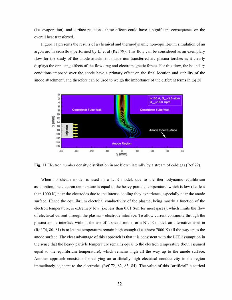
Figure 11 presents the results of a chemical and thermodynamic non-equilibrium simulation of an
argon arc in crossflow performed by Li et al (Ref 79). This flow can be considered as an exemplary
flow for the study of the anode attachment inside non-transferred arc plasma torches as it clearly
displays the opposing effects of the flow drag and electromagnetic forces. For this flow, the boundary
conditions imposed over the anode have a primary effect on the final location and stability of the
anode attachment, and therefore can be used to weigh the importance of the different terms in Eq 28.
Fig. 11 Electron number density distribution in arc blown laterally by a stream of cold gas (Ref 79)
When no sheath model is used in a LTE model, due to the thermodynamic equilibrium
assumption, the electron temperature is equal to the heavy particle temperature, which is low (i.e. less
than 1000 K) near the electrodes due to the intense cooling they experience, especially near the anode
surface. Hence the equilibrium electrical conductivity of the plasma, being mostly a function of the
electron temperature, is extremely low (i.e. less than 0.01 S/m for most gases), which limits the flow
of electrical current through the plasma – electrode interface. To allow current continuity through the
plasma-anode interface without the use of a sheath model or a NLTE model, an alternative used in
(Ref 74, 80, 81) is to let the temperature remain high enough (i.e. above 7000 K) all the way up to the
anode surface. The clear advantage of this approach is that it is consistent with the LTE assumption in
the sense that the heavy particle temperature remains equal to the electron temperature (both assumed
equal to the equilibrium temperature), which remains high all the way up to the anode surface.
Another approach consists of specifying an artificially high electrical conductivity in the region
immediately adjacent to the electrodes (Ref 72, 82, 83, 84). The value of this “artificial” electrical

33
conductivity used in the literature is somewhat arbitrary. The only requirement for its value is that it
needs to be high enough in order to ensure the flow of electrical current from the plasma to the
electrodes. This latter model lets the arc reattach whenever it gets in contact, or “close enough”, to the
anode surface at an axial location which is more thermodynamically favorable, i.e. a location that
produces a configuration of the arc with a lower total voltage drop. However, this type of formation
of a new attachment is different from the reattachment process described in Section 5. Important
studies of the effect of the anode modeling in an arc plasma flow were performed by Lago et al (Ref
23) and later expanded to three-dimensional modeling in Gonzalez et al (Ref 85). Their models
included the effect of metal vapor on the arc and melting of the anode, detailed heat transfer between
plasma and anode (similar to Eq 28), and radiative transfer using view factors.
Fig. 12 Heavy particle temperature across the torch (left), and heavy (center) and electron (right)
temperatures close to the anode surface (Ref 87)
Figure 12 shows time-sequences of the distribution of heavy-species temperature inside the torch
and heavy-species and electron temperatures (Th and Te) over the anode surface obtained with a
NLTE model. The figure shows the significance of the anode heat transfer depicted by the growth of
a new anode attachment spot as well as the large difference in magnitude of the electron and heavy-
particle temperatures over the anode. The size of the spot given by the electron temperature

34
distribution is significantly larger than that given by the heavy-particle temperature. The works of Li
et al (Ref 72) and Park et al (Ref 86) clearly display the size and evolution of the anode attachment as
obtained by LTE simulations.
4.5 Cathode
Cathodes are the source of electrons in thermal plasma torches. The cathode in DC arc plasma
torches used for plasma spraying is thermionic; that is the electrons are emitted as a consequence of
the high temperature of the cathode. The region in front of the cathode can be divided into two
distinctive parts: The ionization region, and the space charge sheath. Similarly to the anode region,
these regions are very small compared to the characteristic length of the flow. Typically there is a
considerable voltage drop in this thin layer and considerable power is deposited in it. This power is a
consequence of the balance between the energy flux of ions and electrons from the plasma to the
cathode surface and the heat removed by the electrons leaving the cathode (Ref 88).
The accurate modeling of the cathode region is quite involved due to the variety of chemical and
electrical phenomena taking place. Furthermore, it has been shown that evaporation of the cathode
material can have a significant effect on the plasma flow dynamics (Ref 89). Indeed, the metal vapor
increases significantly the electrical conductivity of the plasma in front of the cathode, which causes
constriction of the arc. These effects have to be added to the stability of the cathode spot (the region
with highest current density), which is often of primary importance in cathodes whose geometry does
not favor a preferred spot (see Ref 90 for detailed modeling of cathode spot stability).
The large computational cost associated to the self-consistent modeling of the electrode regions
and the plasma flow has prevented them to be widely used in arc plasma torch simulation. A
distinctive example of the coupled modeling of electrodes and thermal plasma flow in an industrial
application is the work of Khokan et al (Ref 91) of the simulation of the arc discharge in a HID lamp.
In their model the cathode region is modeled using the nonlinear surface heating model of Benilov
(Ref 88). The work by Li and Benilov (Ref 92) of the coupled simulation of the arc and cathode
region revealed that the electric power deposited into the cathode region is transported not only to the
cathode, but also to the arc column.
The need to reduce the computational cost of the modeling of the electrode regions in industrial
thermal plasma flows has motivated the development of different sheath models. These models try to
describe in a simplified manner the main physical effects that dominate the electrode – plasma
interface. Particularly significant is the unified approach developed by Lowke et al (Ref 93) which,

35
when applied to the modeling of the cathode, does not require the specification of a current density
profile.
Probably the most common (as well as least expensive) approach used to model the cathode
boundary is to specify the current density profile as boundary condition for the electromagnetic
equations. A common profile used in the DC arc plasma modeling literature has the form:
))(exp(0cathn
cathcathcath R
rJJ −= (Eq 30)
where Jcath is the current density over the cathode surface, r the radial coordinate measured from the
torch axis, and Jcatho0, Rcath, and ncath are parameters that control the shape of the profile, preferably to
mimic experimental measurements. These parameters are not independent as the integration of the
current density profile over the cathode should be equal to the total current imposed. Typically, for
commercial plasma spray torches operating between 100 and 800 A, Jcatho0 is of the order of 108 A/m2,
the exponent ncath varies between 1 for acute conical cathodes (Ref 68, 72) to ~ 4 for more rounded
ones (Ref 84), and the characteristic distance Rcath is typically less than 1 mm.
Fig. 13 Comparison of plasma temperature [K] for a commercial plasma cutting torch with and
without magnetization apparatus; total current = 120 A, nozzle diameter 1.37 mm (Ref 94)
As boundary conditions for the energy conservation, often a specified equilibrium or heavy-
species temperature distribution is imposed over the cathode surface (where the highest temperature is
usually assumed close to the melting point of the cathode material (e.g. ~ 3600 ºC for tungsten),
whereas a zero-gradient condition is imposed for the electron temperature. These conditions are rough
approximations, and when possible, an adequate cathode region model should be employed.

36
The modeling of the cathode region is particularly important in simulations of plasma cutting
torches due to the relatively large cathode tip area, relatively small flow volume, and large current
densities over the cathode. Fig 13 presents simulation results by Colombo et al (Ref 94) of the flow
through a commercial plasma cutting torch. The pronounced constriction of the arc, crucial for
attaining a precise cut, can be observed as well as a localized high temperature region in front of the
cathode.
5. Arc Reattachment Models
5.1 Operating Modes in Non-transferred Arc Torches
The dynamics of the arc inside the torch are mostly the result of the imbalance between the
electromagnetic (or Lorentz) forces, produced by the local curvature of the current path and the self-
induced magnetic field, and the flow drag, caused by the interaction of the incoming cold gas and the
hot, low-density, arc. Because the total voltage drop across the torch is approximately linearly-
dependent on the arc length, the variation of the total voltage drop over time gives an indication of the
arc dynamics inside the torch. The characteristic features of the voltage drop signal over time for
given operating conditions have led to the identification of three distinct modes of operation of the
torch (Ref 95, 96, 97, 98), namely:
• Steady: Characterized by negligible voltage fluctuations and, correspondingly, an almost fixed
position of the arc attachment. This mode is not desirable due to the rapid erosion of the anode.
• Takeover: Characterized by (quasi-) periodic fluctuations of voltage drop and a corresponding
(quasi-) periodic movement of the arc. The spectrum of the voltage signal presents several
dominant frequencies. This operating mode is the most desirable because it allows an adequate
distribution of the heat load to the anode, and produces well defined arc fluctuations.
• Restrike mode: Characterized by a highly unstable, relatively unpredictable movement of the arc
and quasi-chaotic, large amplitude, voltage fluctuations. An arc operating in this mode is very
unstable and relatively unpredictable; the arc reattachment phenomenon plays a dominant role in
the arc dynamics.
For a given torch, the flow can change from the steady mode, to the takeover, and then to the
restrike mode as the mass flow rate is increased or as the total current is decreased; or more precisely
37
as the enthalpy number Nh increases (i.e. Nh is proportional to the mass flow rate and inversely
proportional to the total current squared). Therefore, the operating conditions determine the dynamics
of the arc inside the torch.
5.2 Arc Reattachment Process
Even though the exact mechanisms driving the reattachment process are not completely known
yet, the relatively high electric fields, added to the abundance of excited species around the arc (i.e.
due to UV excitation), and the short time scale of the process, suggests that the arc reattachment is
initiated by a streamer-like breakdown. In a streamer-like breakdown, the new attachment starts with
a continuous avalanche of UV-excited electrons. This streamer connects the arc with the anode in a
region somewhere upstream of the existing arc attachment, creating a conducting channel that allows
the establishment of a new attachment. As the new configuration of the arc has a lower voltage drop,
it is thermodynamically more favorable, and therefore the new attachment remains over the old one,
which is dragged away by the flow. Experimental images of the reattachment process, together with a
schematic representation of the phenomena involved, are shown in Fig. 14. Figure 14 shows the
displacement of the anode attachment, the formation of a new attachment (i.e. a reattachment
process), which causes the momentarily splitting of the current path, and the predominance and
further movement of the new attachment.
To mimic the physical reattachment process, a model mainly faces the questions of where and
how to introduce the new attachment. Where to locate the new attachment translates into the
definition of an adequate breakdown condition, whereas how to introduce the reattachment translates
into the definition of adequate modifications of the flow field in order to mimic the formation of an
attachment.
The detailed modeling of this process is unfeasible with actual computational methods and
computer power, especially when the reattachment process is part of the modeling of a realistic
plasma application. The work by Montijn et al (Ref 99) is a notable example of the simulation of
streamer propagation. A similar model would have to be integrated to an arc flow simulation to
realistically simulate the arc reattachment phenomenon. Therefore, for the simulation of industrial
thermal plasma applications, approximate models are needed which imitate the effects of the
reattachment process within the flow field. Sections 5.3 and 5.4 describe two approaches that have
been successfully applied to the simulation of commercial plasma spray torches.

38
Fig. 14 Schematic representation of the arc reattachment process (left) and experimental high speed
images (right) from (Ref 95)
5.3 Conducting Channel Reattachment Model
This model, developed in (Ref 84), relies on the fact that the dragging of the arc by the flow field
causes the local electric field around the arc to increase. When the local electric field En in the
direction normal to the anode surface exceeds some pre-specified value Eb (model parameter),
namely:
bmaxna EE >=⋅ ,maxnE , (Eq 31)
where na is the normal to the anode surface, the breakdown condition is met. Centered in that location
and in the direction normal to the anode surface, a cylindrical region connecting the arc and the anode
is specified. Within that cylindrical region, the electrical conductivity is modified according to:
),( bmax σσσ ← , (Eq 32)

39
where σb is an artificially high electrical conductivity and σ in the right hand side represents the local
electrical conductivity of the plasma. The reattachment process is mainly driven by the specification
of Eb; the specific value of σb, as well as its spatial variation (σb = σb(x)) only affects the speed of the
process (e.g. larger values of σb produce a faster reattachment). Moreover, if the physical
reattachment process is indeed triggered by the value of the local electric field exceeding certain
breakdown voltage (Eb in the model), it is reasonable to expect that the value of this breakdown
voltage will be a function of the gas composition, and probably only a weak function of the torch
characteristics and operating conditions (i.e. nozzle diameter, mass flow rate, total current).
Because of the free parameter Eb, this reattachment model cannot predict the operating mode of
the torch. The model can only predict the arc dynamics inside a torch operating under given operating
conditions and a given value of Eb. If the model is used to simulate a torch operating under conditions
leading to a takeover (or steady) mode, a high enough value of Eb should be used in order to ensure
that a restrike-like reattachment does not occur. Otherwise, the voltage signal obtained could
resemble that of the restrike mode.
Fig. 15 Temperature distribution and voltage drop during the reattachment process obtained by a LTE
model complemented with a Trelles et al reattachment model (Ref 84)
The time evolution of the temperature distribution and total voltage drop during the formation of
a new arc attachment in a commercial torch operating with Ar-He, 60 slpm, 800 A, and straight gas
injection are shown in Fig. 15 for Eb = 5·104 V/m. When the local electric field is below the pre-

40
specified value of Eb, the arc is dragged by the flow, and its length and the total voltage drop
increases linearly (from frame 1 to 2). As soon as the breakdown condition is met (Eq 31), the
reattachment model is applied. Frame 2 shows the growing of a high temperature appendage in the
direction towards the anode, mimicking the formation of a new attachment. In frame 3, the new
attachment forms and, as indicated by the voltage drop between 3 and 4, rapidly overcomes the old
attachment, which is dragged away by the flow. Frames 5 to 7 show the dragging of the new
attachment accompanied by an approximately linear increase of the total voltage drop. The rapid
decrease of voltage drop from 3 to 4 resembles the restrike mode. The results reported in Ref 84
suggest that, by tuning the value of Eb, the principal parameter in this reattachment model, one could
be able to match the voltage signal obtained experimentally.
5.4 Hot Gas Column Reattachment Model
The reattachment model developed by Chazelas et al (Ref 80) is also based on the fact that the
stretching of the arc column due to the drag forces exerted by the plasma forming gas flow leads to an
increase of the voltage drop between the arc column fringes and the anode surface. The model
considers that the boundary layer surrounding the arc column breaks when the voltage, and so the
electric field, overcomes a certain threshold value. The breakdown process is modelled as follows:
(i) The thickness δ of the boundary layer that covers the anode surface is defined by the thickness
between the region of the flow with an electrical conductivity lower than 150 S/m and the anode
surface. For Ar-H2 plasma-forming gas, the value of 150 S/m corresponds to a critical
temperature Tc (see Section 3.1, Fig. 4) under which the plasma gas acts as an insulating layer.
(ii) The electric field between the edge of the arc column and the anode wall δφ /)( 0 aVE −=
(where φ0 is the potential in the plasma and Va the potential at the anode surface) is calculated in
the whole boundary layer and compared with a critical field Eb, under which no breakdown
process can occur. A value of Eb of around few 104 V/m had been chosen because it is now well
established that the critical electric field is decreased by one order of magnitude when
temperatures higher than 3000 K are encountered.
(iii) When the value Eb is reached at a particular location M, a short-circuit occurs and a new arc
attachment at the nozzle wall appears.

41
A simple model is used for the ignition of a new arc root attachment by re-arcing. It consists of
imposing, a high-enough gas column temperature that connects the arc column fringe to the anode
wall, at the location where the electric field was found to be greater than Eb.
The time-evolution of the temperature distribution and total voltage drop during the formation of
a new arc attachment in a commercial torch operating with Ar-H2, 45-15 slpm, 600 A, 6-mm nozzle
diameter and straight gas injection are shown in Fig. 16 for Eb = 5·104 V/m. When the local electric
field is below the pre-specified value of Eb, the arc is dragged by the flow, and its length and the total
voltage drop increase linearly (from frame 1 to 2). As soon as the breakdown condition is satisfied,
the reattachment model is applied (frames 2 and 3). Frame 3 shows the growing of a high temperature
appendage in the direction towards the anode, mimicking the formation of a new attachment. In frame
3, the new attachment is formed and, as indicated by the voltage drop, rapidly overcomes the old
attachment, which is dragged away by the flow. Frame 5 shows the dragging of the new attachment
accompanied by an approximately linear increase of the total voltage drop.
Fig. 16 Temperature distribution and arc voltage during the reattachment process obtained by a LTE
model complemented with a Chazelas’ et al reattachment model (Ref 80)
Each breakdown is associated with a negative jump of the voltage. In the case shown in Fig. 16,
the latter was found to be 20 ± 5 V. The peak occurs at intervals of about 80 µs, i.e. at an average
frequency of about 13 kHz. The predicted time-average torch voltage is about 65 V, close to the
actual one of 60 V experimentally measured. The results reveal that decreasing the arc current
intensity or increasing the plasma gas flow rate results in an increase of the average boundary layer

42
thickness δ, favouring higher voltage jump amplitude ∆φ (Ref 100, 81). As mentioned by Trelles et
al, (Ref 84) tuning the value of Eb, the principal parameter in the reattachment model, permits to
either match the frequency or the voltage jump amplitude, the other quantity moving in the opposite
manner.
5.5 Reattachment in Non-Equilibrium Models
To the best knowledge of the authors, no reattachment model has been coupled to a non-
equilibrium plasma torch simulation yet. This may be due in part to the complexity and computational
cost of non-equilibrium simulations and the added difficulty to attain convergence when a
reattachment model is used. Figure 17 presents snapshots of simulation results by Trelles et al (Ref
75) of the reattachment process obtained with an LTE and a NLTE model for a torch operating with
argon, 60 slpm, and 400 A, and swirl injection. The reattachment model of Ref 84 is used in the LTE
model, whereas no reattachment model is used in the NLTE model. The figure shows how the anode
attachment moves upstream initially; then, due to the net angular momentum over the arc, the
curvature of the arc increases, pushing the arc towards the opposite side of the original attachment.
These dynamics are interrupted by the occurrence of the arc reattachment process.
Interestingly, the NLTE simulations (which use no reattachment model) display the growth of a
high temperature appendage (see arrows in the Th and Te plots in Fig. 17) in a region upstream after
the point of maximum total voltage drop (which could be correlated with the maximum value of
electric field). The formation of the high temperature appendage seems to be driven by high values of
the local effective electric field and high values of electron temperature. Even though swirl injection
is used, due to the relatively short time scale of the reattachment process, the arc reattaches at almost
the opposite side of the original attachment (Ref 101). The reattachment process occurs in a natural
manner mimicking the steady and/or takeover modes of operation of the torch. It must be noted that
arcs in pure argon as simulated here rarely display a restrike behavior because the boundary layer is
usually rather thin. It is expected that non-equilibrium simulations of the restrike mode will require
the use of a reattachment model to produce more accurate results.
As explained previously (Section 4.4), in a LTE model a reattachment can occur either due to the
application of the reattachment model (i.e. when the breakdown condition is satisfied) or due to the
arc dynamics causing the arc to get “close enough” to the anode. The growth of a high temperature
region from the arc column towards the anode can be observed in the LTE results in Fig 17 which

43
eventually initiates the formation of a new attachment. Moreover, the application of the reattachment
model clearly disrupts the flow significantly.
Fig. 17 Heavy particle temperature (left), electron temperature (centre) obtained with a non-
equilibrium model, and equilibrium temperature (right) obtained with an equilibrium model during
the reattachment process (Ref 75)
6. Conclusions and What’s Next
Great progress has been achieved in the simulation of DC arc torches. We have reached a state in
which three-dimensional and time-dependent simulations with detailed geometry description of
industrial torches are reaching widespread use. These simulations have helped to achieve a better
understanding of the operation of DC arc torches and have sometimes led to improved torch designs
and plasma processes. However, these simulations still lack of complete predictive power, especially
for the simulation of non-transferred arc torches. Several improvements could be achieved with
higher computing power and massive use of parallel computing. But most importantly, the
complexity of the models needed to describe the different processes that take place, has been the
limiting factor for more detailed and accurate plasma torch simulations. The ready availability of
different “physics modules” in commercial CFD software has eased the incorporation of several

44
physical processes and a wider range of models into plasma torch modeling. Unfortunately, the
models in commercial CFD software are most often not implemented with thermal plasma flow
applications in mind, and therefore, often rely on unrealistic assumptions (e.g. turbulence models that
assume constant thermodynamic and transport properties, neglect of electromagnetic forces, etc.).
Nevertheless, users of commercial CFD software frequently need to develop user-defined routines to
be integrated into their simulations in order to account for the missing physical models. In this regard,
the use of research, in-house, developed software generally provide the most faithful models for
plasma torch simulation (e.g. electrode boundary models, electromagnetic equations). To the previous
exposition, we have to add that several processes involved in the description of the plasma flow are
not yet understood at the level that accurate models are available. A paramount example of this is the
initiation of arc reattachment phenomena.
Some of the developments we anticipate will greatly improve the predictive power of DC arc
plasma torch simulations are:
• Widespread use of thermodynamic and chemical non-equilibrium models. These non-equilibrium
models necessarily need to use sound values of non-equilibrium thermodynamic and transport
properties. The accurate modeling of these properties still represents a big challenge, both in
terms of implementation and on computational cost.
• Incorporation of the electrodes into the computational domain. This would have a significant
effect in the boundary conditions for electromagnetic equations.
• Detailed modeling of electrodes and electrode processes, particularly heat transfer mechanisms
and electric current flows. Furthermore, surface chemistry and phase change phenomena (e.g.
electrode material evaporation, anode erosion) should be incorporated into these models.
• Use of more faithful geometry representations. This is particularly important for the analysis of
commercial plasma torches and for their design optimization.
• In the case of non-transferred arc torches, more physical and mathematically sound models of the
arc reattachment process are needed. It is reasonable to expect that the incorporation of such
models into a thermodynamic non-equilibrium plasma torch simulation will be able to reproduce
the steady, takeover, and restrike modes of operation without the need for tuning parameters.
• Regarding the modeling of turbulence, DNSs would be highly desirable, especially in order to
understand the mechanisms for turbulence formation inside the torch, particularly the role of
fluid-dynamic, thermal, and electromagnetic instabilities and the arc reattachment process. DNS
data would also guide the development of turbulence models (LES, RANS, and DES) suitable for
thermal plasma flow simulations. Furthermore, detailed turbulence modeling would be of great
45
benefit for the understanding of plasma – powder interaction, especially for ultra-fine and nano-
scale powders, as these processes are influenced by the fine scale structures of the flow.
Additionally, detailed comparison of simulation results against experimental measuremens of
turbulent flow characteristics (e.g. correlations, mean quantities, dissipation rates) is required to
validate any turbulent thermal plasma flow model.
• Rigorous validation with experimental data. The recent availability of high-fidelity three-
dimensional and often time-dependent experimental data, such as the analysis of the anode
attachment region in Ref 102, or of the plasma jet in Ref 103, raises the quality, validity, and
resolution expected from numerical simulations.
We expect that direct current arc plasma torch modeling will be playing an increasingly important
role in the design of thermal plasma processes. Several industrial applications will obtain better
yields, higher efficiencies, and improved economical advantage thanks to the systematic use of
numerical simulations to guide and/or aid the design and optimization of their processes.

46
References
1. M. I . Boulos, ,P. Fauchais, and E. Pfender, Thermal Plasmas: Fundamentals and Applications,
Plenum Press, New York, 1994
2. H. Goedbloed and S. Poedts, Principles of Magnetohydrodynamics, Cambridge University Press,
United Kingdom, 2004
3. A. B. Murphy, A Comparison of Treatments of Diffusion in Thermal Plasmas, J. Phys. D: Appl.
Phys., 1996, 29, p 1922–1932
4. J. D. Ramshaw and C. H. Chang. Ambipolar Diffusion in Two-Temperature Multicomponent
Plasmas, Plasma Chemistry and Plasma Proccessing, 1993, 13(3), p 489-498
5. J. D. Ramshaw and C. H. Chang, Multicomponent Diffusion in Two-temperature
Magnetohydrodynamics, Physical Review E, 1996, 53(6), p 6382-6388
6. A. B. Murphy, Diffusion in Equilibrium Mixtures of Ionized Gases, Physical Review E, 1993,
48(5), p 3594-3603
7. V. Rat, J. Aubreton, M. F. Elchinger, P. Fauchais, and A. B. Murphy, Diffusion in Two-
Temperature Thermal Plasmas, Physical Review E, 2002, 66(026409), p 1-20
8. E. S. Oran and J. P. Boris, Numerical Simulation of Reactive Flow, Second Edition, Cambridge
University Press, 2001
9. T. W. Megli, H. Krier, R. L. Burton, and A. Mertogul, Two-Temperature Plasma Modeling of
Nitrogen/Hydrogen Arcjets, Journal of Propulsion and Power, 1996, 12(6), p 1062-1069
10. J. H. Park, Three-Dimensional Nonequilibrium Numerical Modeling of Arc-Anode Attachment in
Direct-Current Electric Arcs, Ph.D. Thesis, University of Minnesota, 2003
11. K. Ragaller, Investigations on Instabilities of Electric Arcs, Zeitschrift Fur
Naturforschung, 1974, 29a, p 556-567
12. L. Niemeyer and K. Ragaller, Development of Turbulence by the Interaction of Gas Flow
with Plasmas, Zeitschrift Fur Naturforschung, 1973, 28a, p 1281-1289
13. P. Domingo and T. Benazzouz, Direct Numerical Simulation and Modeling of a Nonequilibrium
Turbulent Plasma, AIAA Journal, 2000, 38(1), p 73-78
14. S. B. Pope, Ten questions Concerning the Large-Eddy Simulation of Turbulent Flows, New
Journal of Physics, 2004, 6(35),
15. Y. Bazilevs, V. M. Calo, J. A. Cottrell, T. J. R. Hughes, A. Reali, G. Scovazzi, Variational
Multiscale Residual-Based Turbulence Modeling for Large Eddy Simulation of Incompressible

47
Flows, Computer Methods in Applied Mechanics and Engineering, 2007, Volume 197, 4(1), p
173-201
16. V. Colombo, A. Concetti, E. Ghedini, Time Dependent 3d Large Eddy Simulation of a DC
Nontransferred Arc Plasma Spraying Torch With Particle Injections, 2007 IEEE Pulsed Power
and Plasma Science Conference (PPPS), New Mexico, U.S.A., 2007
17. C. Delalondre, O. Simonin, Turbulence Modeling in Electric Arcs, Heat and Mass Transfer under
Plasma Conditions, edited by P Fauchais, Begell House, 1995, pp 1-15
18. B. E. Launder and D. B. Spalding. Lectures in Mathematical Models of Turbulence. Academic
Press, London, England, 1972
19. Fluent 6.3 User’s Guide, http://www.fluent.com/, 2008
20. J. Menart, J. Heberlein and E. Pfender, Theoretical Radiative Transport Results for a Free-
Burning Arc Using a Line-by-Line Technique, J. Phys. D: Appl. Phys., 1999, 32, p 55–63
21. H. Nordborg and A. A. Iordanidis, Self-consistent Radiation Based Modeling of Electric Arcs: I.
Efficient Radiation Approximations, J. Phys. D: Appl. Phys., 2008, 41 135205, p 1-10
22. A. A. Iordanidis and C. M. Franck, Self-consistent Radiation-based Simulation of Electric Arcs:
II. Application to Gas Circuit Breakers, J. Phys. D: Appl. Phys., 2008, 41, 135206, p 1-9
23. F. Lago, J. J. Gonzalez, P. Freton and A. Gleizes, A Numerical Modelling of an Electric Arc and
its Interaction with the Anode: Part I. The Two-Dimensional Model, J. Phys. D: Appl. Phys.,
2004, 37, p 883–897
24. Y. Tanaka, Time-Dependent Two-Temperature Chemically Non-Equilibrium Modelling of High-
Power Ar–N2 Pulse-Modulated Inductively Coupled Plasmas At Atmospheric Pressure, J. Phys.
D: Appl. Phys., 2006, 39, p 307–319
25. J. J. Lowke, E. R. Capriotti, Calculation of Temperature Profiles of High Pressure
Electric Arcs Using Diffusion Approximation For Radiation Transfer, JQSRT 9 (2), 207,
1969
26. J.J. Lowke, Predictions of Arc Temperature Profiles Using Approximate Emission
Coefficients For Radiation Losses, JQSRT 14 (2), 111-122, 1974
27. A. Gleizes, J. J. Gonzalez, B. Liani and G. Raynal, Calculation of Net Emission Coefficient of
Thermal Plasmas In Mixtures of Gas I With Metallic Vapour, J. Phys. D: Appl. Phys., 1993, 26, p
1921-1927
28. J. Menart and S. Malik, Net Emission Coefficients For Argon-Iron Thermal Plasmas, J.
Phys. D: Appl. Phys. 2002, 35(9), p 867-874
48
29. Riad H., Cheddadi A., Neghizadeh-Kashani Y., Gleizes A., Radiation emission of
thermal plasma in O2, H2O, CO2 and air, High Temperature Material Processes, 1999, 3
(1), p 25-37
30. Y. Naghizadeh-Kashani, Y. Cressault, A. Gleizes, Net Emission Coefficient of Air
Thermal Plasmas, Journal of Physics D: Applied Physics, 2002, 35(22), p 2925-2934
31. R. Hannachi,, Y. Cressault, Ph. Teulet, Z. Ben Lakhdar and A Gleizes, Net Emission of H2O–air–
MgCl2/CaCl2/NaCl Thermal Plasmas, J. Phys. D: Appl. Phys., 2008, 41, p 205-212
32. A. Essoltani, P. Proulx, M. I. Boulos, A. Gleizes, Effect of the Presence of Iron Vapors
On the Volumetric Emission of Ar/Fe and Ar/Fe/H2 Plasmas, Plasma Chemistry and
Plasma Processing, 1994, 14(3), p 301-303
33. Pateyron B and Delluc G 1986 Freedownload Software TTWinner, http://ttwinner.free.fr
34. A. Gleizes, J. J. Gonzalez and P. Freton, Thermal Plasma Modelling, J. Phys D: Appl.
Phys, 2005, 38(9), p R153-R183
35. S. Chapman and S T. G.Cowling, The Mathematical Theory of Non Uniform Gases,
Cambridge University Press, 1958
36. J. O. Hirschfelder, C. F. Curtis and R. B. Bird, Molecular Theory of Gases and Liquids, Editorial
Wiley, New York, 1964
37. L. Jr Spitzer and R. Harm, Transport Phenomena in a Completely Ionized Gas,1953 Phys.
Rev.89, 977-981
38. J. N. Butler and R. S. Brokaw, Thermal conductivity of gas mixtures in chemical
equilibrium, 1957 J. Chem. Phys. 26 1636
39. R. S. Devoto, Transport Coefficients of Partially Ionized Argon, Phys. Fluids, 1967, 10, p 354
40. A. B. Murphy, Thermal Plasmas in Gas Mixtures, J. Phys. D: Appl. Phys., 2001, 34, p R151
41. M. Capitelli, R. Celiberto, C. Gorse, D. Giordano, Transport Properties of High Temperature Air
Components: A Review, Plasma Chemistry and Plasma Processing, 1995, 16(S1), p S269-302
42. B. Chervy, A. Gleizes and M Razafinimanana, Thermodynamic Properties And Transport
Coefficients In SF6-Cu Mixtures At Temperatures of 300-30000 K And Pressures of 0.1-1 Mpa,
J. Phys. D: Appl. Phys., 1994, 27(6), p 1193-1206
43. Y. Cressault and A. Gleizes, Thermodynamic Properties And Transport Coefficients In
Ar-H2-Cu Plasma, J. Phys. D:Appl. Phys., 2004, 37, p 560-72

49
44. Y. Cressault, R. Hannachi, Ph. Teulet, A. Gleizes, J.-P. Gonnet and J.-.Y Battandier, Influence of
metallic vapours on the properties of air thermal plasmas Plasma Sources Sci. Technol. 17 (2008)
paper 035016 (9 pages)
45. A. B. Murphy, Transport Coefficients of argon, nitrogen, oxygen, argon-nitrogen, and argon-
oxygen plasmas, Plasma Chem. And Plasm. Proc., 1994, 14(4), p 451-490
46. A. B. Murphy, Transport coefficients of hydrogen and argon-hydrogen plasmas, Plasma Chem.
and Plasm. Proc., 2000, 20(3), p 279-297
47. A. Murphy, Transport Coefficients of Air, Argon-Air, Nitrogen-Air, And Oxygen-Air Plasmas,
Plasma Chem. And. Plasm. Proc., 1995, 15(2), p 279-307
48. B. Pateyron, M. -F. Elchinger, G. Delluc, P. Fauchais, Thermodynamic And Transport
Properties of Ar-H2 And Ar-He Plasma Gases Used For Spraying At Atmospheric
Pressure. I: Properties of the Mixtures, Plasma Chemistry and Plasma Processing, 1992,
12(4), p 421 – 448
49. B. Sourd, J. Aubreton, M. F. Elchinger, M. Labrot and U. Michon, High Temperature Transport
Coefficients In E/C/H/N/O Mixtures, J. Phys. D: Appl. Phys., 2006, 39, p 1105-1119.
50. V. Rat, A. B. Murphy, J. Aubreton, M. F. Elchinger and P. Fauchais , J. Phys. D: Appl. Phys. 41
(2008) Article Number: 183001
51. V. Rat, P. Andre, J. Aubreton, M. F. Elchinger, P. Fauchais and A. Lefort A, Two-temperature
transport coefficients in Argon-hydrogen Plasma-Part I, Plasma Chem. Plasma Process.,
2002, 22(4) 475–493
52. V. Rat, P. Andre, J. Aubreton, M. F. Elchinger, P. Fauchais and D. Vacher, Transport
Coefficients Including Diffusion In A Two-Temperature Argon Plasma, J. Phys. D: Appl.
Phys., 2002, 35, p 981–991,
53. G. J. Cliteur, K. Suzuki, Y. Tanaka, T. Sakuta, T. Matsubara, Y. Yokomizu and T.
Matsumura, On the Determination of the Multi-Temperature SF6 Plasma Composition, 1999 J.
Phys. D: Appl. Phys., 32, P 1851–6
54. R. S. Devoto, Simplified Expression For the Transport Properties of Ionized Monoatomic
Gases, Phys. Fluids, 1967, 10, p 2105–12
55. C. Bonnefoi,, Contribution to the study of methods to solve the Botzmann’s equation in a
two-temperature plasma:example Ar-H2 mixture, 1983, PhD thesis University of
Limoges, France (in French)

50
56. J. Aubreton, C. Bonnefoi and J. M. Mexmain Calculation of hermodynamic Properties
and Transport Coefficient in a non-equilibrium Ar-O2 plasma, in French, Rev. Phys.
Appl., 1986 21 365–76
57. V. Rat, P. André, J. Aubreton, M. F. Elchinger, P. Fauchais and A. Lefort, Transport
properties in a two-temperature plasma, Phys. Rev. E, 2001, 64 26409–28
58. R S Devoto Transport properties of ionized monoatomic gases, Phys. Fluids, 1966 9
1230–1240
59. V. Rat, P. Andre´, J. Aubreton, M. F. Elchinger, P. Fauchais, and A. Lefort, Two-Temperature
Transport Coefficients in Argon–Hydrogen Plasmas—II: Inelastic Processes and Influence of
Composition, Plasma Chemistry and Plasma Processing, 2002, 22 (4), 475-493
60. S. Ghorui, J. V. R. Heberlein and E. Pfender, Thermodynamic and Transport Properties of Two-
Temperature Oxygen Plasmas, Plasma Chem. Plasma Proc., 2007, 27, p 267–291
61. J. Aubreton J, M F Elchinger and P.Fauchais,. New method to calculate thermodynamic and
transport properties of a multi-temperature plasma: application to N2 plasma. Plasma Chem.
Plasma Proc. ,1998, 18, 1–27
62. J. Aubreton, M. F. Elchinger, P. Fauchais, V. Rat and P. André, Thermodynamic and transport
properties of a ternary Ar–H2–He mixture out of equilibrium up to 30 000 K at atmospheric
pressure. J. Phys. D: Appl. Phys. 2004. 37, 2232–2246
63. J. Aubreton, M. F. Elchinger, V. Rat and P. Fauchais, Two-temperature transport coefficients in
argon–helium thermal plasmas. J. Phys. D: Appl. Phys., 2004, 37, 34–41
64. A. Aubreton, M.F. Elchinger, Transport properties in non-equilibrium argon, copper and argon–
copper thermal plasmas. J. Phys. D: Appl. Phys., 2003, 36, 1798–1805
65. R. N. Gupta, J.M. Yos and R. A. Thompson,Review of Reaction Rates and thermodynamic
Transport Properties For The 11-Species Air Model For Chemical and Thermal Nonequilibrium
Calculations To 30000 K, NASA Report 1998, TM-10-1528
66. S. Ghorui, J.V.R. Heberlein, E. Pfender, Thermodynamic and Transport Properties of Two-
Temperature Nitrogen-Oxygen Plasma, Plasma Chem. Plasma Process, 2008, 28, p 553-582
67. V. Colombo, E. Ghedini, P. Sanibondi ,Thermodynamic And Transport Properties In Non-
Equilibrium Argon, Oxygen And Nitrogen Thermal Plasmas, Progress in Nuclear Energy, 2008,
50, p 921–933
68. J. J. Gonzalez, P. Freton and A. Gleizes, Comparisons Between Two- And Three-Dimensional
Models: Gas Injection And Arc Attachment, J. Phys. D: Appl. Phys., 2002, 35, p 3181–3191

51
69. P. Freton, J. J. Gonzalez, F. Camy Peyret and A. Gleizes, Complementary Experimental And
Theoretical Approaches To the Determination of the Plasma Characteristics In A Cutting Plasma
Torch, J. Phys. D: Appl. Phys., 2003, 36, p 1269–1283
70. T. Colonius, Modeling Artificial Boundary Conditions For Compressible Flow, Annu. Rev. Fluid
Mech., 2004, 36, p 315–45
71. J. P. Trelles, E. Pfender and J. V.R. Heberlein, Thermal Non-Equilibrium Simulation of an Arc
Plasma Jet, IEEE Trans. Plasma Science, 2008, 36(4), p 1026-1027
72. He-Ping Li, E Pfender and Xi Chen, Application of Steenbeck’s Minimum Principle For Three-
Dimensional Modeling of DC Arc Plasma Torches, J. Phys. D: Appl. Phys., 2003, 36, p 1084–
1096
73. C. Baudry, A. Vardelle, G. Mariaux, C. Delalondre, and E. Meillot, Three-Dimensional and
Time-Dependent Model of the Dynamic Behavior of the Arc in a Plasma Spray Torch,
Proceedings of the International Thermal Spray Conference, Japan, 2004
74. C. Baudry, A. Vardelle, and G. Mariaux, Numerical Modeling of a DC Non-Transferred Plasma
Torch: Movement of the Arc Anode Attachment and Resulting Anode Erosion, High
Temperature Plasma Processes, 2005, 9, p 1-15
75. J. P. Trelles, J. V.R. Heberlein, and E. Pfender, Non-equilibrium Modeling of Arc Plasma
Torches, Journal of Physics D: Applied Physics, 2007, 40, p 5635-5648
76. M. A. Lieberman and A. J. Lichtenberg, Principles of Plasma Discharges and Materials
Processing, John Wiley & Sons Inc, Hoboken, New Jersey, 2005
77. M. Tanaka, H. Terasaki, M. Ushio, and J. J. Lowke, Numerical Study of a Free-burning Argon
Arc with Anode Melting, Plasma Chemistry and Plasma Processing, 2003, 23(3), p 108-117
78. H. A. Dinulescu and E. Pfender, Analysis of the Anode Boundary Layer of High Intensity
Arcs, J. Appl. Phys., 1980, 51, p 3149–57
79. H.-P. Li, J. Heberlein, and E. Pfender, Three-Dimensional, Nonequilibrium Effects in a High-
Intensity Blown Arc, IEEE Transactions on Plasma Science, 2005, 33(2), p 402-403 80. C. Chazelas, E. Moreau, G. Mariaux, and A. Vardelle, Numerical Modeling of Arc Behavior in a
DC Plasma Torch, High Temperature Materials Processing, 2006, 10, p 393-406
81. E. Moreau, C. Chazelas, G. Mariaux, and A. Vardelle, Modeling of the Restrike Mode Operation
of a DC Plasma Spray Torch, Journal of Thermal Spray Technology, 2006, 15(4), p 524-530
82. H.-P. Li and X. Chen, Three-Dimensional Modelling of A Dc Non-Transferred Arc Plasma
Torch, J. Phys. D: Appl. Phys. 2001, 34, p L99–L102
52
83. V. Colombo, E. Ghedini, Time Dependent 3-D Simulation of a DC Non-Transferred Arc Plasma
Torch: Anode Attachment and Downstream Region Effects, Proceedings of the 17th International
Symposium on Plasma Chemistry (ISPC), Toronto, Canada, p 169-170, 2005
84. J. P. Trelles, E. Pfender, and J. V. R. Heberlein, Modeling of the Arc Reattachment Process in
Plasma Torches, Journal of Physics D: Applied Physics, 2007, 40, p 5635-5648
85. J. J. Gonzalez, F. Lago, P. Freton, M. Masquere and X. Franceries, Numerical Modelling of An
Electric Arc And Its Interaction With the Anode: Part II. The Three-Dimensional Model—
Influence of External Forces On the Arc Column, J. Phys. D: Appl. Phys., 2005, 38, p 306–318
86. J. M. Park, K. S. Kim, T. H. Hwang, and S. H. Hong, Three-Dimensional Modeling of Arc Root
Rotation by External Magnetic Field in Non-transferred Thermal Plasma Torches, IEEE
Transactions on Plasma Science, 2004, 32(2), p 479-487
87. J. P. Trelles, J. V.R. Heberlein, and E. Pfender, The Reattachment Process in Non-Equilibrium
Arc Simulations, IEEE Trans. Plasma Science, 2008, 36(4), p 1024-1025
88. M. S. Benilov and A. Marotta, A Model of the Cathode Region of Atmospheric Pressure Arc, J.
Phys. D: Appl. Phys., 1995, 28, p 1869-1882
89. K. Etemadi, G. Y. Zhao and J. Mostaghimi, Impact of Cathode Evaporation On A Free-Burning
Arc, J. Phys. D.: Appl. Phys., 1989, 22, p 1692-1696
90. M. S. Benilov, M. Carpaij, and M. D. Cunha, 3D Modelling of Heating of Thermionic Cathodes
By High-Pressure Arc Plasmas, J. Phys. D: Appl. Phys., 2006, 39, 2124–2134
91. K. C. Paul, T. Takemura, T. Hiramoto, A. Erraki, F. Dawson, G. Zissis, J. J. Gonzalez, A.
Gleizes, M. S. Benilov, and J. D. Lavers, Self Consistent Model of HID Lamp for Design
Applications, IEEE Transactions On Plasma Science, 2006, 34(4), p 1536-1547
92. H.-P. Li and M. S. Benilov, Effect of A Near-Cathode Sheath On Heat Transfer In High-Pressure
Arc Plasmas, J. Phys. D: Appl. Phys., 2007, 40, p 2010–2017
93. Lowke, J. J., Morrow, R., and Haidar, J., A Simplified Unified Theory of Arcs and their
Electrodes, Journal of Physics D: Applied Physics, No. 30, 2033-2042, 1997
94. V. Colombo, A. Concetti, E. Ghedini S. Dallavalle, M. Vancini, Understanding Plasma Fluid
Dynamics Inside Plasma Torches Through Advanced Modeling, 34th IEEE International
Conference on Plasma Science and the 16th IEEE International Pulsed Power Conference
proceedings, June 17-22, 2007, Albuquerque, New Mexico, p 1423-1428
95. S. A. Wutzke, E. Pfender, and E. R. G. Eckert, Symptomatic Behavior of an Electric Arc with a
Superimposed Flow, AIAA Journal, 1967, 6(8), p 1474-82
96. J. F. Coudert, M. P. Planche, and P. Fauchais, Characterization of D.C. Plasma Torch Voltage
Fluctuations, Plasma Chemistry and Plasma Processing, 1996, 16(1), p 211s-227s

53
97. J.-L. Dorier, M. Gindrat, C. Hollenstein, A. Salito, M. Loch, G. Barbezat, Time Resolved
Imaging of Anodic Arc Root Behavior During Fluctuations of a DC Plasma Spraying Torch,
IEEE Transactions on Plasma Science, 2001, 29(3), p 494-500
98. Z. Duan and J. V. R. Heberlein, Arc Instabilities in a Plasma Spray Torch, Journal of Thermal
Spray Technology, 2002, 11(1), 44-51
99. C. Montijn, B. Meulenbroek, U. Ebert, and W. Hundsdorfer, Numerical Simulations and
Conformal Analysis of Growing and Branching Negative Discharge Streamers, IEEE
Transactions on Plasma Science, 2005, 33(2), p 260-261
100. Z. Duan, K. Wittmann, J.F. Coudert, J. Heberlein and P. Fauchais, “Effects of the
cold gas boundary layer on arc fluctuations,” Proc. 14th Intl. Conf. on Plasma Chem.,
eds. M. Hrabovsky, M. Konrád, V. Kopecky (Institute of Plasma Physics AS CR; Prague,
Czech Republic; Aug. 2-6, 1999) vol. I, p 233-238.
101. J. P. Trelles, E. Pfender, and J. V. R. Heberlein, Multiscale Finite Element Modeling of Arc
Dynamics in a DC Plasma Torch, Plasma Chemistry and Plasma Processing, 2006, 26, p 557-575
102. G. Yang and J. V. Heberlein, The Anode Region of High Intensity Arcs With Cold Cross
Flow, J. Phys. D: Appl. Phys., 2007, 40, p 5649–5662
103. J. Hlina, J. Sonsky, V. Nenicka and A. Zachar, Statistics of Turbulent Structures in a Thermal
Plasma Jet, J. Phys. D: Appl. Phys., 2005, 38, p 1760-1768